WO2011129295A1 - 排気センサー - Google Patents
排気センサー Download PDFInfo
- Publication number
- WO2011129295A1 WO2011129295A1 PCT/JP2011/058993 JP2011058993W WO2011129295A1 WO 2011129295 A1 WO2011129295 A1 WO 2011129295A1 JP 2011058993 W JP2011058993 W JP 2011058993W WO 2011129295 A1 WO2011129295 A1 WO 2011129295A1
- Authority
- WO
- WIPO (PCT)
- Prior art keywords
- exhaust
- sensor
- gas
- sensor body
- exhaust gas
- Prior art date
- Legal status (The legal status is an assumption and is not a legal conclusion. Google has not performed a legal analysis and makes no representation as to the accuracy of the status listed.)
- Ceased
Links
Images

Classifications
-
- F—MECHANICAL ENGINEERING; LIGHTING; HEATING; WEAPONS; BLASTING
- F01—MACHINES OR ENGINES IN GENERAL; ENGINE PLANTS IN GENERAL; STEAM ENGINES
- F01N—GAS-FLOW SILENCERS OR EXHAUST APPARATUS FOR MACHINES OR ENGINES IN GENERAL; GAS-FLOW SILENCERS OR EXHAUST APPARATUS FOR INTERNAL-COMBUSTION ENGINES
- F01N13/00—Exhaust or silencing apparatus characterised by constructional features
- F01N13/008—Mounting or arrangement of exhaust sensors in or on exhaust apparatus
-
- F—MECHANICAL ENGINEERING; LIGHTING; HEATING; WEAPONS; BLASTING
- F01—MACHINES OR ENGINES IN GENERAL; ENGINE PLANTS IN GENERAL; STEAM ENGINES
- F01N—GAS-FLOW SILENCERS OR EXHAUST APPARATUS FOR MACHINES OR ENGINES IN GENERAL; GAS-FLOW SILENCERS OR EXHAUST APPARATUS FOR INTERNAL-COMBUSTION ENGINES
- F01N2560/00—Exhaust systems with means for detecting or measuring exhaust gas components or characteristics
Definitions
- the present invention relates to an exhaust sensor for measuring an exhaust gas component.
- the exhaust sensor is disposed, for example, on the exhaust gas downstream side of the exhaust gas aftertreatment device in the exhaust pipe of the engine and measures the exhaust gas component.
- an exhaust gas aftertreatment device for example, there is a DPF (diesel particulate filter) that collects PM (particulate matter) contained in exhaust gas.
- PM (particulate matter) emission amount There is a PM sensor that detects
- the exhaust sensor when the exhaust sensor is attached to the exhaust pipe of the engine in order to take the exhaust gas into the exhaust sensor (sensing part), exhaust the exhaust sensor so that the exhaust sensor (sensor body) is orthogonal to the exhaust gas flow. It is desirable to insert into the tube from the outside. In this case, if there is no appropriate pressure difference between the gas inlet and the gas outlet formed in the sensor body exposed in the exhaust pipe, the exhaust gas stays inside the sensor body, and the combustion products in the exhaust gas (soot, Carbide, sulfur oxide, etc.) may adhere to the inside of the sensor body, and the function of the exhaust sensor may be impaired.
- an object of the present invention is to suppress the stagnation of exhaust gas inside the sensor body by generating an appropriate pressure difference between the gas inlet and the gas outlet formed in the sensor body.
- the present invention provides an exhaust sensor for measuring an exhaust gas component, a cylindrical sensor body inserted into an exhaust pipe of an engine, and facing the exhaust gas upstream of the sensor body.
- the area of the gas outlet may be larger than the area of the gas inlet.
- a liquid discharge hole communicating with the inside of the sensor body may be provided at the lower end of the sensor body.
- the gas inlet may be formed at one end of the sensor body, and the gas outlet may be formed at the other end of the sensor body.
- the sensor body may be inserted into the exhaust pipe so that the longitudinal direction of the sensor body is orthogonal to the longitudinal direction of the exhaust pipe.
- a turbine may be disposed in the exhaust pipe, and the sensor main body may be inserted in the exhaust pipe downstream of the turbine.
- An exhaust gas aftertreatment device may be disposed in the exhaust pipe downstream of the exhaust gas from the turbine, and the sensor main body may be inserted into the exhaust pipe downstream of the exhaust gas aftertreatment device.
- FIG. 1 is a schematic view of an engine equipped with an exhaust sensor according to an embodiment of the present invention.
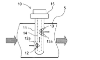
- FIG. 2 is an enlarged view of a main part of FIG.
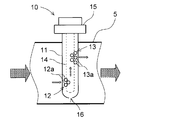
- FIG. 3 is an enlarged view of a main part of an engine to which an exhaust sensor according to another embodiment is mounted.
- 1 is an engine (in this embodiment, a diesel engine), 2 is an intake pipe connected to the intake port 1a of the engine 1, 3 is an air cleaner disposed in the intake pipe 2, and 4 is an air cleaner 3.
- a turbo compressor turbocharger compressor
- 5 is an exhaust pipe (tail pipe) connected to the exhaust port 1 b of the engine 1
- Reference numeral 6 denotes a turbine that is disposed in the exhaust pipe 5 and drives the turbo compressor 4
- 7 is an exhaust gas aftertreatment device that is disposed in the exhaust pipe 5 on the downstream side of the exhaust gas from the turbine 6.
- the exhaust gas aftertreatment device 7 includes, for example, a DPF (diesel particulate filter) that collects PM (particulate matter) contained in the exhaust gas.
- DPF diesel particulate filter
- the exhaust sensor 10 of the present embodiment is a vehicle-mounted sensor that assumes OBD (On-board diagnostics), and charges the supplied air with a charge. It is a PM sensor that detects the amount of discharge.
- OBD On-board diagnostics
- the exhaust sensor 10 of the present embodiment includes a cylindrical (bottomed or sheathed) sensor body 11 that is inserted into the exhaust pipe 5 of the engine 1, and one end of the sensor body 11.
- a cover 15 that closes the other end side of the sensor body 11.
- the exhaust sensor 10 is inserted into the exhaust pipe 5 from outside and above so that the sensor body 11 is orthogonal to the exhaust gas flow inside the exhaust pipe 5. That is, in the present embodiment, the exhaust sensor 10 is inserted into the exhaust pipe 5 from the outside and above so that the longitudinal direction of the sensor body 11 is orthogonal to the longitudinal direction of the exhaust pipe 5.
- the senor body 11 and the nozzle 14 are arranged concentrically with each other. Further, although not shown, an air compressor is connected to the base end of the nozzle 14, and air is supplied to the nozzle 14 by this air compressor.
- the gas inlet 12 is directed to the upstream side of the exhaust pipe 5 (exhaust gas upstream side) and the gas outlet 13 is directed to the exhaust pipe 5 with respect to the exhaust gas flow inside the exhaust pipe 5. It has a structure oriented toward the downstream side (downstream side of the exhaust gas). That is, the gas inlet 12 faces the upstream side of the exhaust gas and opens in the sensor body 11, and the gas outlet 13 faces the downstream side of the exhaust gas and opens in the sensor body 11. Are arranged at intervals in the circumferential direction of the sensor body 11.
- the area of the gas outlet 13 is larger than the area of the gas inlet 12.
- each of the gas outlet 13 and the gas inlet 12 includes a plurality of holes 13 a and 12 a having the same area, and the number of holes 13 a constituting the gas outlet 13 (five in the illustrated example) configures the gas inlet 12. More than the number of holes 12a to be formed (three in the illustrated example).
- a cylindrical sensor main body 11 inserted into the exhaust pipe 5 of the engine 1, a gas inlet 12 opened to the sensor main body 11 facing the exhaust gas upstream side, and an exhaust gas downstream side of the sensor main body 11.
- the exhaust gas sensor 13 is provided with a gas outlet 13 that is open to face the exhaust gas flow, and the gas inlet 12 is upstream of the exhaust pipe 5 (exhaust gas upstream side) with respect to the exhaust gas flow inside the exhaust pipe 5. Since the gas outlet 13 is directed to the exhaust pipe 5 downstream side (exhaust gas downstream side), it is easy to generate a pressure difference between the gas inlet 12 and the gas outlet 13, and the exhaust gas is inside the sensor body 11. Can flow smoothly, and the retention of exhaust gas in the sensor body 11 can be suppressed.
- the exhaust gas flow inside the sensor body 11 is smooth, efficient sensing by the exhaust sensor 10 is possible. Furthermore, since the exhaust gas stays inside the sensor body 11 can be suppressed, it is possible to prevent the exhaust sensor 10 from being deteriorated by the exhaust gas.
- the area of the gas outlet 13 is made larger than the area of the gas inlet 12, a pressure difference can be more easily generated between the gas inlet 12 and the gas outlet 13, and the inside of the sensor body 11 is increased. It is possible to introduce exhaust gas more efficiently into the vehicle.
- a liquid discharge communicating with the inside of the sensor main body 11 is provided at the lower end of the sensor main body 11 so that liquid such as condensed water generated in the sensor main body 11 after the engine 1 is stopped can be discharged by gravity.
- a hole 16 may be provided. In the illustrated example, the liquid discharge hole 16 is provided at the tip (lower end) of the sensor body 11, but the position of the liquid discharge hole 16 is appropriate depending on the mounting angle of the exhaust sensor 10 (sensor body 11) with respect to the exhaust pipe 5. Shall be set to
- the exhaust sensor 10 is not limited to a PM sensor, and may be a sensor that measures exhaust gas components other than PM.
Landscapes
- Engineering & Computer Science (AREA)
- Chemical & Material Sciences (AREA)
- Analytical Chemistry (AREA)
- Combustion & Propulsion (AREA)
- Mechanical Engineering (AREA)
- General Engineering & Computer Science (AREA)
- Exhaust Gas After Treatment (AREA)
- Testing Of Engines (AREA)
- Combined Controls Of Internal Combustion Engines (AREA)
- Exhaust Silencers (AREA)
Abstract
センサー本体に形成されるガス入口とガス出口との間に適切な圧力差を発生させることにより、センサー本体内部での排気ガスの滞留を抑制する。 排気ガス成分の測定を行う排気センサー10において、エンジン1の排気管5に挿入される筒状のセンサー本体11と、センサー本体11に排気ガス上流側に臨んで開口されたガス入口12と、センサー本体11に排気ガス下流側に臨んで開口されたガス出口13とを備え、ガス入口12とガス出口13との圧力差により、排気ガスがガス入口12からセンサー本体11内部に取り込まれた後にガス出口13から排出されるようにした。
Description
本発明は、排気ガス成分の測定を行う排気センサーに関する。
排気センサーは、例えば、エンジンの排気管における排ガス後処理装置の排気ガス下流側に配設され、排気ガス成分の測定を行うものである。排ガス後処理装置としては、例えば、排気ガス中に含まれるPM(粒子状物質)を捕集するDPF(ディーゼルパティキュレートフィルタ)があり、排気センサーとしては、例えば、PM(粒子状物質)排出量を検知するPMセンサーがある。
ところで、排気ガスを排気センサー内部(センシング部)に取り込むために、排気センサーをエンジンの排気管に取り付ける場合、排気センサー(センサー本体)が排気ガス流れに対して直交するように、排気センサーを排気管に外側から挿入することが望ましい。この場合、排気管内に露出するセンサー本体に形成されるガス入口とガス出口との間に適切な圧力差がないとセンサー本体内部に排気ガスが滞留し、排気ガス中の燃焼生成物(煤、炭化物、硫黄酸化物等)がセンサー本体内部に付着し、排気センサーの機能が損なわれる虞がある。
例えば、排気管内に露出するセンサー本体の同一周上にガス出口とガス入口とを設けていると、ガス入口とガス出口との間に圧力差が発生しにくい。
そこで、本発明の目的は、センサー本体に形成されるガス入口とガス出口との間に適切な圧力差を発生させることにより、センサー本体内部での排気ガスの滞留を抑制することにある。
上述の目的を達成するために、本発明は、排気ガス成分の測定を行う排気センサーにおいて、エンジンの排気管に挿入される筒状のセンサー本体と、該センサー本体に排気ガス上流側に臨んで開口されたガス入口と、前記センサー本体に排気ガス下流側に臨んで開口されたガス出口とを備え、前記ガス入口と前記ガス出口との圧力差により、排気ガスが前記ガス入口から前記センサー本体内部に取り込まれた後に前記ガス出口から排出されるようにしたものである。
前記ガス出口の面積を前記ガス入口の面積よりも大きくしても良い。
前記センサー本体の下端部に前記センサー本体内部に連通する液体排出孔を設けても良い。
前記ガス入口が前記センサー本体の一端部に形成され、前記ガス出口が前記センサー本体の他端部に形成されていても良い。
前記センサー本体の長手方向が前記排気管の長手方向に対して直交するように、前記センサー本体が前記排気管に挿入されていても良い。
前記排気管にタービンが配設され、該タービンよりも排気ガス下流側の前記排気管に前記センサー本体が挿入されていても良い。
前記タービンよりも排気ガス下流側の前記排気管に排ガス後処理装置が配設され、該排ガス後処理装置よりも排気ガス下流側の前記排気管に前記センサー本体が挿入されていても良い。
本発明によれば、センサー本体に形成されるガス入口とガス出口との間に適切な圧力差を発生させることにより、センサー本体内部での排気ガスの滞留を抑制することができるという優れた効果を奏する。
以下、本発明の好適な実施形態を添付図面に基づいて詳述する。
図1中、1はエンジン(本実施形態では、ディーゼルエンジン)、2はエンジン1の吸気ポート1aに接続された吸気管、3は吸気管2に配設されたエアクリーナー、4はエアクリーナー3よりも吸気下流側の吸気管2に配設されエンジン1に供給する吸気を昇圧するターボコンプレッサー(ターボチャージャーのコンプレッサー)、5はエンジン1の排気ポート1bに接続された排気管(テールパイプ)、6は排気管5に配設されターボコンプレッサー4を駆動するタービン、7はタービン6よりも排気ガス下流側の排気管5に配設された排ガス後処理装置である。排ガス後処理装置7は、例えば、排気ガス中に含まれるPM(粒子状物質)を捕集するDPF(ディーゼルパティキュレートフィルタ)を有する。
本実施形態の排気センサー10は、OBD(On-board diagnostics;自己故障診断)対応を想定した車載可能なセンサーであって、供給されるエアーに電荷をチャージし、電荷の変化量からPM(粒子状物質)排出量を検知するPMセンサーである。
図2に示すように、本実施形態の排気センサー10は、エンジン1の排気管5に挿入される筒状(有底筒状或いは鞘状)のセンサー本体11と、センサー本体11の一端部に形成されたガス入口12と、センサー本体11の他端部に形成されたガス出口13と、センサー本体11内部に収容され先端からエアーを噴出するノズル14と、エアーに電荷をチャージする電極(図示せず)と、センサー本体11の他端部側を閉塞するカバー15とを備えている。
本実施形態では、センサー本体11が排気管5内部の排気ガス流れに対して直交するように、排気センサー10が排気管5に外側且つ上方から挿入されている。つまり、本実施形態では、センサー本体11の長手方向が排気管5の長手方向に対して直交するように、排気センサー10が排気管5に外側且つ上方から挿入されている。
また、本実施形態では、センサー本体11とノズル14とは、互いに同心的に配置されている。さらに、図示はしないが、ノズル14の基端にはエアーコンプレッサーが接続されており、このエアコンプレッサーによってエアーがノズル14に供給されるようになっている。
また、本実施形態に係る排気センサー10は、排気管5内部の排気ガス流れに対して、ガス入口12が排気管5上流側(排気ガス上流側)へ指向し、ガス出口13が排気管5下流側(排気ガス下流側)へ指向した構造を有している。つまり、ガス入口12は排気ガス上流側に臨んでセンサー本体11に開口されていると共に、ガス出口13は排気ガス下流側に臨んでセンサー本体11に開口されており、ガス入口12とガス出口13とはセンサー本体11の周方向に間隔を隔てて配置されている。
本実施形態では、ガス出口13の面積をガス入口12の面積よりも大きくしている。図示例では、ガス出口13及びガス入口12はそれぞれ、複数の同一面積の孔13a、12aからなり、ガス出口13を構成する孔13aの数(図示例では、5個)がガス入口12を構成する孔12aの数(図示例では、3個)よりも多くなるようにしている。
本実施形態の作用を説明する。
本実施形態では、エンジン1の排気管5に挿入される筒状のセンサー本体11と、センサー本体11に排気ガス上流側に臨んで開口されたガス入口12と、センサー本体11に排気ガス下流側に臨んで開口されたガス出口13とを備えて排気センサー10を構成しており、排気管5内部の排気ガス流れに対して、ガス入口12が排気管5上流側(排気ガス上流側)へ指向し、ガス出口13が排気管5下流側(排気ガス下流側)へ指向しているので、ガス入口12とガス出口13との間に圧力差を発生させやすく、排気ガスがセンサー本体11内部をスムースに流れるようにすることができ、センサー本体11内部での排気ガスの滞留を抑制することができる。また、センサー本体11内部の排気ガス流れがスムースなので、排気センサー10による効率的なセンシングが可能となる。さらに、センサー本体11内部での排気ガスの滞留を抑制できるので、排気ガスによる排気センサー10の劣化を防止することができる。
また、本実施形態によれば、ガス出口13の面積をガス入口12の面積よりも大きくしたので、ガス入口12とガス出口13との間に圧力差をより発生しやすくでき、センサー本体11内部へのより効率的な排気ガスの導入が可能となる。
ところで、排気ガスを排気センサー10内部に取り込むために、排気センサー10をエンジン1の排気管5に取り付ける場合、エンジン1停止後にセンサー本体11内部の温度が低下し露点を下回ると、排気ガス中の燃焼生成物(水、硫黄酸化物等)が凝縮水となって、センサー本体11内部に溜まり、排気センサー10の機能を損なう虞がある。そこで、図3に示すように、センサー本体11の下端部に、エンジン1停止後にセンサー本体11内部に発生する凝縮水等の液体を重力で排出できるように、センサー本体11内部に連通する液体排出孔16を設けると良い。図示例では、センサー本体11の先端(下端)に液体排出孔16を設けているが、排気管5に対する排気センサー10(センサー本体11)の取り付け角度に応じて、液体排出孔16の位置は適切に設定されるものとする。
以上、本発明の好適な実施形態について説明したが、本発明は上述の実施形態には限定されず他の様々な実施形態を採ることが可能である。
例えば、排気センサー10は、PMセンサーに限定はされず、PM以外の排気ガス成分を測定するセンサーであっても良い。
1 エンジン
2 吸気管
3 エアクリーナー
4 ターボコンプレッサー
5 排気管(テールパイプ)
6 タービン
7 排ガス後処理装置
10 排気センサー
11 センサー本体
12 ガス入口
13 ガス出口
16 液体排出孔
2 吸気管
3 エアクリーナー
4 ターボコンプレッサー
5 排気管(テールパイプ)
6 タービン
7 排ガス後処理装置
10 排気センサー
11 センサー本体
12 ガス入口
13 ガス出口
16 液体排出孔
Claims (7)
- 排気ガス成分の測定を行う排気センサーにおいて、
エンジンの排気管に挿入される筒状のセンサー本体と、該センサー本体に排気ガス上流側に臨んで開口されたガス入口と、前記センサー本体に排気ガス下流側に臨んで開口されたガス出口とを備え、
前記ガス入口と前記ガス出口との圧力差により、排気ガスが前記ガス入口から前記センサー本体内部に取り込まれた後に前記ガス出口から排出されるようにしたことを特徴とする排気センサー。 - 前記ガス出口の面積を前記ガス入口の面積よりも大きくした請求項1に記載の排気センサー。
- 前記センサー本体の下端部に前記センサー本体内部に連通する液体排出孔を設けた請求項1又は2に記載の排気センサー。
- 前記ガス入口が前記センサー本体の一端部に形成され、前記ガス出口が前記センサー本体の他端部に形成された請求項1から3のいずれかに記載の排気センサー。
- 前記センサー本体の長手方向が前記排気管の長手方向に対して直交するように、前記センサー本体が前記排気管に挿入された請求項1から4のいずれかに記載の排気センサー。
- 前記排気管にタービンが配設され、該タービンよりも排気ガス下流側の前記排気管に前記センサー本体が挿入された請求項1から5のいずれかに記載の排気センサー。
- 前記タービンよりも排気ガス下流側の前記排気管に排ガス後処理装置が配設され、該排ガス後処理装置よりも排気ガス下流側の前記排気管に前記センサー本体が挿入された請求項1から6のいずれかに記載の排気センサー。
Applications Claiming Priority (2)
| Application Number | Priority Date | Filing Date | Title |
|---|---|---|---|
| JP2010-094339 | 2010-04-15 | ||
| JP2010094339A JP5736662B2 (ja) | 2010-04-15 | 2010-04-15 | 排気センサー |
Publications (1)
| Publication Number | Publication Date |
|---|---|
| WO2011129295A1 true WO2011129295A1 (ja) | 2011-10-20 |
Family
ID=44798668
Family Applications (1)
| Application Number | Title | Priority Date | Filing Date |
|---|---|---|---|
| PCT/JP2011/058993 Ceased WO2011129295A1 (ja) | 2010-04-15 | 2011-04-11 | 排気センサー |
Country Status (2)
| Country | Link |
|---|---|
| JP (1) | JP5736662B2 (ja) |
| WO (1) | WO2011129295A1 (ja) |
Cited By (3)
| Publication number | Priority date | Publication date | Assignee | Title |
|---|---|---|---|---|
| CN105888798A (zh) * | 2015-02-17 | 2016-08-24 | 福特环球技术公司 | 用于感测微粒物质的系统 |
| CN107916979A (zh) * | 2016-10-10 | 2018-04-17 | 福特环球技术公司 | 用于排气微粒物质感测的方法和系统 |
| CN115616164A (zh) * | 2022-10-26 | 2023-01-17 | 福建云一科技有限公司 | 一种气体传感器 |
Families Citing this family (2)
| Publication number | Priority date | Publication date | Assignee | Title |
|---|---|---|---|---|
| JP5429368B2 (ja) * | 2010-04-30 | 2014-02-26 | トヨタ自動車株式会社 | Pm量検出装置 |
| WO2020179356A1 (ja) * | 2019-03-01 | 2020-09-10 | 日本碍子株式会社 | 微粒子検出素子及び微粒子検出器 |
Citations (7)
| Publication number | Priority date | Publication date | Assignee | Title |
|---|---|---|---|---|
| JPS59197847A (ja) * | 1983-04-25 | 1984-11-09 | Ngk Spark Plug Co Ltd | スモーク濃度センサ |
| JPS60256046A (ja) * | 1984-06-01 | 1985-12-17 | Hitachi Ltd | 酸素濃度検出器 |
| JPH1090127A (ja) * | 1996-09-17 | 1998-04-10 | Fuji Electric Co Ltd | 直接挿入型測定ガスサンプリング構造 |
| US7063731B2 (en) * | 2000-04-12 | 2006-06-20 | Goyen Controls Co. Pty Ltd | Method and apparatus for detecting particles in a gas flow |
| JP2008268137A (ja) * | 2007-04-25 | 2008-11-06 | Nissho Shipping Co Ltd | 内燃機関排ガスの粒状物質検出方法および内燃機関の燃焼制御方法ならびに装置 |
| JP2010281239A (ja) * | 2009-06-03 | 2010-12-16 | Denso Corp | 排気センサ管理装置および排気センサ管理方法 |
| JP2011080439A (ja) * | 2009-10-09 | 2011-04-21 | Nippon Soken Inc | パティキュレートフィルタの異常検出装置 |
Family Cites Families (1)
| Publication number | Priority date | Publication date | Assignee | Title |
|---|---|---|---|---|
| JPS6023723Y2 (ja) * | 1979-12-27 | 1985-07-15 | 富士電機株式会社 | 酸素ガス分析計 |
-
2010
- 2010-04-15 JP JP2010094339A patent/JP5736662B2/ja not_active Expired - Fee Related
-
2011
- 2011-04-11 WO PCT/JP2011/058993 patent/WO2011129295A1/ja not_active Ceased
Patent Citations (7)
| Publication number | Priority date | Publication date | Assignee | Title |
|---|---|---|---|---|
| JPS59197847A (ja) * | 1983-04-25 | 1984-11-09 | Ngk Spark Plug Co Ltd | スモーク濃度センサ |
| JPS60256046A (ja) * | 1984-06-01 | 1985-12-17 | Hitachi Ltd | 酸素濃度検出器 |
| JPH1090127A (ja) * | 1996-09-17 | 1998-04-10 | Fuji Electric Co Ltd | 直接挿入型測定ガスサンプリング構造 |
| US7063731B2 (en) * | 2000-04-12 | 2006-06-20 | Goyen Controls Co. Pty Ltd | Method and apparatus for detecting particles in a gas flow |
| JP2008268137A (ja) * | 2007-04-25 | 2008-11-06 | Nissho Shipping Co Ltd | 内燃機関排ガスの粒状物質検出方法および内燃機関の燃焼制御方法ならびに装置 |
| JP2010281239A (ja) * | 2009-06-03 | 2010-12-16 | Denso Corp | 排気センサ管理装置および排気センサ管理方法 |
| JP2011080439A (ja) * | 2009-10-09 | 2011-04-21 | Nippon Soken Inc | パティキュレートフィルタの異常検出装置 |
Cited By (4)
| Publication number | Priority date | Publication date | Assignee | Title |
|---|---|---|---|---|
| CN105888798A (zh) * | 2015-02-17 | 2016-08-24 | 福特环球技术公司 | 用于感测微粒物质的系统 |
| CN105888798B (zh) * | 2015-02-17 | 2020-12-25 | 福特环球技术公司 | 用于感测微粒物质的系统 |
| CN107916979A (zh) * | 2016-10-10 | 2018-04-17 | 福特环球技术公司 | 用于排气微粒物质感测的方法和系统 |
| CN115616164A (zh) * | 2022-10-26 | 2023-01-17 | 福建云一科技有限公司 | 一种气体传感器 |
Also Published As
| Publication number | Publication date |
|---|---|
| JP5736662B2 (ja) | 2015-06-17 |
| JP2011226824A (ja) | 2011-11-10 |
Similar Documents
| Publication | Publication Date | Title |
|---|---|---|
| WO2011129296A1 (ja) | 排気センサー | |
| US10041455B2 (en) | Humidity sensor device arranged in a choke portion of an internal combustion engine intake air passage | |
| CN103808782B (zh) | 运行用于机动车的以确定废气成分的传感器的方法和装置 | |
| JP5047352B2 (ja) | 排気ターボ過給機のハウジング構造 | |
| US10247079B2 (en) | Exhaust gas purification system of internal combustion engine having turbocharger | |
| JP5736662B2 (ja) | 排気センサー | |
| CN110088443A (zh) | 导流罩组件 | |
| US10557398B2 (en) | Exhaust pipe structure for internal combustion engine | |
| US9982590B2 (en) | Internal-combustion-engine supercharger | |
| JP5494068B2 (ja) | エンジンの排気装置 | |
| JP5510017B2 (ja) | 排気センサー配置構造 | |
| US20180202397A1 (en) | Intake apparatus and dump truck | |
| CN104870990A (zh) | 用于内燃发动机的具有涡流的进入气体传感器 | |
| CN112746884A (zh) | 发动机的排气系统 | |
| CN107060970B (zh) | 用于微粒过滤器泄漏检测的方法和系统 | |
| JP2018003641A5 (ja) | ||
| JP2019132261A (ja) | 内燃機関の吸気装置 | |
| JP5999324B2 (ja) | 内燃機関の吸気系構造 | |
| JP5738155B2 (ja) | エンジンの還元剤噴射ノズル | |
| US9421488B2 (en) | Cleanable particle separator and motor vehicle having at least one particle separator | |
| WO2019065594A1 (ja) | 内燃機関のegr装置 | |
| CN108571404A (zh) | 发动机的排气装置 | |
| JP2021032143A (ja) | ブローバイガス処理装置 | |
| JP2019007361A (ja) | フィルタエレメントの製造方法、フィルタエレメント、およびエアクリーナ |
Legal Events
| Date | Code | Title | Description |
|---|---|---|---|
| 121 | Ep: the epo has been informed by wipo that ep was designated in this application |
Ref document number: 11768816 Country of ref document: EP Kind code of ref document: A1 |
|
| NENP | Non-entry into the national phase |
Ref country code: DE |
|
| 122 | Ep: pct application non-entry in european phase |
Ref document number: 11768816 Country of ref document: EP Kind code of ref document: A1 |