WO2011129158A1 - 照明装置、表示装置及びテレビ受信装置 - Google Patents
照明装置、表示装置及びテレビ受信装置 Download PDFInfo
- Publication number
- WO2011129158A1 WO2011129158A1 PCT/JP2011/054717 JP2011054717W WO2011129158A1 WO 2011129158 A1 WO2011129158 A1 WO 2011129158A1 JP 2011054717 W JP2011054717 W JP 2011054717W WO 2011129158 A1 WO2011129158 A1 WO 2011129158A1
- Authority
- WO
- WIPO (PCT)
- Prior art keywords
- reinforcing
- bottom plate
- backlight
- backlight chassis
- plate
- Prior art date
- Legal status (The legal status is an assumption and is not a legal conclusion. Google has not performed a legal analysis and makes no representation as to the accuracy of the status listed.)
- Ceased
Links
Images




Classifications
-
- G—PHYSICS
- G02—OPTICS
- G02F—OPTICAL DEVICES OR ARRANGEMENTS FOR THE CONTROL OF LIGHT BY MODIFICATION OF THE OPTICAL PROPERTIES OF THE MEDIA OF THE ELEMENTS INVOLVED THEREIN; NON-LINEAR OPTICS; FREQUENCY-CHANGING OF LIGHT; OPTICAL LOGIC ELEMENTS; OPTICAL ANALOGUE/DIGITAL CONVERTERS
- G02F1/00—Devices or arrangements for the control of the intensity, colour, phase, polarisation or direction of light arriving from an independent light source, e.g. switching, gating or modulating; Non-linear optics
- G02F1/01—Devices or arrangements for the control of the intensity, colour, phase, polarisation or direction of light arriving from an independent light source, e.g. switching, gating or modulating; Non-linear optics for the control of the intensity, phase, polarisation or colour
- G02F1/13—Devices or arrangements for the control of the intensity, colour, phase, polarisation or direction of light arriving from an independent light source, e.g. switching, gating or modulating; Non-linear optics for the control of the intensity, phase, polarisation or colour based on liquid crystals, e.g. single liquid crystal display cells
- G02F1/133—Constructional arrangements; Operation of liquid crystal cells; Circuit arrangements
- G02F1/1333—Constructional arrangements; Manufacturing methods
- G02F1/1335—Structural association of cells with optical devices, e.g. polarisers or reflectors
- G02F1/1336—Illuminating devices
- G02F1/133602—Direct backlight
- G02F1/133608—Direct backlight including particular frames or supporting means
-
- G—PHYSICS
- G02—OPTICS
- G02F—OPTICAL DEVICES OR ARRANGEMENTS FOR THE CONTROL OF LIGHT BY MODIFICATION OF THE OPTICAL PROPERTIES OF THE MEDIA OF THE ELEMENTS INVOLVED THEREIN; NON-LINEAR OPTICS; FREQUENCY-CHANGING OF LIGHT; OPTICAL LOGIC ELEMENTS; OPTICAL ANALOGUE/DIGITAL CONVERTERS
- G02F1/00—Devices or arrangements for the control of the intensity, colour, phase, polarisation or direction of light arriving from an independent light source, e.g. switching, gating or modulating; Non-linear optics
- G02F1/01—Devices or arrangements for the control of the intensity, colour, phase, polarisation or direction of light arriving from an independent light source, e.g. switching, gating or modulating; Non-linear optics for the control of the intensity, phase, polarisation or colour
- G02F1/13—Devices or arrangements for the control of the intensity, colour, phase, polarisation or direction of light arriving from an independent light source, e.g. switching, gating or modulating; Non-linear optics for the control of the intensity, phase, polarisation or colour based on liquid crystals, e.g. single liquid crystal display cells
- G02F1/133—Constructional arrangements; Operation of liquid crystal cells; Circuit arrangements
- G02F1/1333—Constructional arrangements; Manufacturing methods
- G02F1/133308—Support structures for LCD panels, e.g. frames or bezels
- G02F1/133314—Back frames
-
- G—PHYSICS
- G02—OPTICS
- G02F—OPTICAL DEVICES OR ARRANGEMENTS FOR THE CONTROL OF LIGHT BY MODIFICATION OF THE OPTICAL PROPERTIES OF THE MEDIA OF THE ELEMENTS INVOLVED THEREIN; NON-LINEAR OPTICS; FREQUENCY-CHANGING OF LIGHT; OPTICAL LOGIC ELEMENTS; OPTICAL ANALOGUE/DIGITAL CONVERTERS
- G02F1/00—Devices or arrangements for the control of the intensity, colour, phase, polarisation or direction of light arriving from an independent light source, e.g. switching, gating or modulating; Non-linear optics
- G02F1/01—Devices or arrangements for the control of the intensity, colour, phase, polarisation or direction of light arriving from an independent light source, e.g. switching, gating or modulating; Non-linear optics for the control of the intensity, phase, polarisation or colour
- G02F1/13—Devices or arrangements for the control of the intensity, colour, phase, polarisation or direction of light arriving from an independent light source, e.g. switching, gating or modulating; Non-linear optics for the control of the intensity, phase, polarisation or colour based on liquid crystals, e.g. single liquid crystal display cells
- G02F1/133—Constructional arrangements; Operation of liquid crystal cells; Circuit arrangements
- G02F1/1333—Constructional arrangements; Manufacturing methods
- G02F1/1335—Structural association of cells with optical devices, e.g. polarisers or reflectors
- G02F1/1336—Illuminating devices
- G02F1/133602—Direct backlight
- G02F1/133604—Direct backlight with lamps
-
- G—PHYSICS
- G02—OPTICS
- G02F—OPTICAL DEVICES OR ARRANGEMENTS FOR THE CONTROL OF LIGHT BY MODIFICATION OF THE OPTICAL PROPERTIES OF THE MEDIA OF THE ELEMENTS INVOLVED THEREIN; NON-LINEAR OPTICS; FREQUENCY-CHANGING OF LIGHT; OPTICAL LOGIC ELEMENTS; OPTICAL ANALOGUE/DIGITAL CONVERTERS
- G02F2201/00—Constructional arrangements not provided for in groups G02F1/00 - G02F7/00
- G02F2201/46—Fixing elements
-
- G—PHYSICS
- G02—OPTICS
- G02F—OPTICAL DEVICES OR ARRANGEMENTS FOR THE CONTROL OF LIGHT BY MODIFICATION OF THE OPTICAL PROPERTIES OF THE MEDIA OF THE ELEMENTS INVOLVED THEREIN; NON-LINEAR OPTICS; FREQUENCY-CHANGING OF LIGHT; OPTICAL LOGIC ELEMENTS; OPTICAL ANALOGUE/DIGITAL CONVERTERS
- G02F2201/00—Constructional arrangements not provided for in groups G02F1/00 - G02F7/00
- G02F2201/50—Protective arrangements
- G02F2201/505—Arrangements improving the resistance to acoustic resonance like noise
Definitions
- the present invention relates to a lighting device, a display device, and a television receiver.
- a backlight device described in Patent Document 1 is known as an example of a backlight device used in a display device.
- a plurality of lamps discharge tubes
- These plurality of lamps are made of cold cathode tubes, and are driven by a method of dimming with a predetermined period, specifically, a pulse width modulation method (PWM method) as shown in FIG. It has become.
- PWM method pulse width modulation method
- An object of this invention is to provide the illuminating device which can prevent thru
- the technology disclosed in the present specification includes a discharge tube, a bottom plate, and a side plate that rises from a peripheral edge of the bottom plate to the first main surface side of the bottom plate, and the technology is provided on the first main surface side of the bottom plate.
- a reinforcing member having an accommodating member that accommodates the discharge tube, a fixing portion fixed to the side plate, and a reinforcing portion that contacts the second main surface of the bottom plate of the accommodating member and is connected to the fixing portion.
- a lighting device comprising:
- the reinforcing portion is fixed to the side plate of the housing member that does not generate vibration due to resonance with the discharge tube via the fixing portion, the vibration of the bottom plate of the housing member due to resonance is It can suppress by the reinforcement part contact
- the reinforcing portion may have a plate shape, and a plate surface thereof may be in contact with the second main surface of the bottom plate of the housing member. According to this configuration, the vibration of the bottom plate of the housing member can be effectively suppressed by the plate surface of the reinforcing portion.
- the reinforcing member includes a plurality of the fixing portions, and the plurality of fixing portions are respectively fixed to the different side plates of the housing member, and the reinforcing portions of the reinforcing member are respectively connected to the fixing portions having different ends. It may be connected. According to this configuration, since the reinforcing portion is firmly fixed to the side plate of the housing member by the plurality of fixing portions, the vibration suppressing effect by the reinforcing portion can be enhanced, and the vibration of the bottom plate of the housing member can be further suppressed. .
- the plurality of fixing portions may be respectively fixed to at least a pair of the side plates opposed to the housing member.
- a reinforcement part will be distribute
- the reinforcing portion of the reinforcing member may be arranged on a diagonal line of the second main surface of the bottom plate. According to this configuration, the vibration of the bottom plate of the housing member can be effectively suppressed by the reinforcing portion.
- the reinforcing member may have a plurality of the reinforcing portions. According to this configuration, vibration of the bottom plate of the housing member can be further suppressed by the plurality of reinforcing portions.
- the fixed portion and the reinforcing portion may be integrally formed.
- the connection strength between the fixed portion and the reinforcing portion is low, it is difficult to obtain the vibration suppressing effect by the reinforcing portion.
- the reinforcement part is not influenced by the connection strength between a fixing
- the reinforcing member may be formed of a material having rigidity equal to or higher than that of the housing member. According to this structure, deterioration of the reinforcement part by suppressing the vibration of the bottom plate of the housing member can be suppressed.
- the technology disclosed in this specification can also be expressed as a display device including a display panel that performs display using light from the above-described lighting device.
- a display device in which the display panel is a liquid crystal panel using liquid crystal is also new and useful.
- a television receiver provided with the above display device is also new and useful. According to the display device and the television set described above, the display area can be increased.
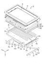
- FIG. 1 is an exploded perspective view of a television receiver TV according to Embodiment 1.
- FIG. An exploded perspective view of the liquid crystal display device 10 is shown.
- the top view which looked at the backlight apparatus 24 from the front side is shown.
- the rear view which looked at the backlight apparatus 24 from the back side is shown.
- FIG. 5 is a cross-sectional view of the backlight device 24, and shows a cross-sectional configuration of the AA cross section of FIG.
- the perspective view which looked at the backlight apparatus 24 from the back side is shown.
- the rear view which looked at the backlight apparatus 74 which concerns on Embodiment 2 from the back side is shown.
- the rear view which looked at the backlight apparatus 124 which concerns on Embodiment 3 from the back side is shown.
- the back view which looked at the backlight apparatus 174 which concerns on Embodiment 4 from the back side is shown.
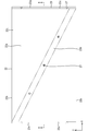
- An explanatory view showing a driving mode of a cold cathode tube is shown.
- Embodiment 1 will be described with reference to the drawings.
- a part of each drawing shows an X-axis, a Y-axis, and a Z-axis, and each axis direction is drawn in a common direction in each drawing.
- the Y-axis direction coincides with the vertical direction
- the X-axis direction coincides with the horizontal direction.
- the vertical direction is used as a reference for upper and lower descriptions.
- FIG. 1 is an exploded perspective view of the television receiver TV according to the first embodiment.
- the television receiver TV includes a liquid crystal display device 10, front and back cabinets Ca and Cb that are accommodated so as to sandwich the display device D, a power source P, a tuner T, and a stand S.
- FIG. 2 shows an exploded perspective view of the liquid crystal display device 10.
- the upper side shown in FIG. 2 is the front side, and the lower side is the back side.
- the liquid crystal display device 10 has a horizontally long rectangular shape as a whole, and includes a liquid crystal panel 16 as a display panel and a backlight device 24 as an external light source. 12 and the like are integrally held.
- the liquid crystal panel 16 has a configuration in which a pair of transparent (highly translucent) glass substrates are bonded together with a predetermined gap therebetween, and a liquid crystal layer (not shown) is sealed between the glass substrates. Is done.
- One glass substrate is provided with a switching element (for example, TFT) connected to a source wiring and a gate wiring orthogonal to each other, a pixel electrode connected to the switching element, an alignment film, and the like.
- the substrate is provided with a color filter and counter electrodes in which colored portions such as R (red), G (green), and B (blue) are arranged in a predetermined arrangement, and an alignment film.
- image data and various control signals necessary for displaying an image are supplied to a source wiring, a gate wiring, a counter electrode, and the like from a drive circuit board (not shown).
- a polarizing plate (not shown) is disposed outside both glass substrates.
- the backlight device 24 includes a frame 14, an optical member 18, a backlight chassis 22, and a reinforcing member 23.
- the frame 14 has a frame shape and supports the liquid crystal panel 16 along the inner edge.
- the optical member 18 is formed by laminating a diffusion plate 18a, a diffusion sheet 18b, a lens sheet 18c, and a reflective polarizing plate 18d in order from the back side.
- the diffusion sheet 18b, the lens sheet 18c, and the reflective polarizing plate 18d have a function of converting light emitted from a discharge tube 28 described later and passing through the diffusion plate 18a into planar light.
- a liquid crystal panel 16 is installed on the upper surface side of the reflective polarizing plate 18 d, and the optical member 18 is disposed between the discharge tube 28 and the liquid crystal panel 16.
- the backlight chassis 22 has a substantially box shape opened to the front side (light emission side, liquid crystal panel 16 side).
- the backlight chassis 22 is made of, for example, a metal such as an aluminum material, and includes a bottom plate 22a having a rectangular shape in plan view, side plates 22b rising from outer edges of both long sides of the bottom plate 22a, and a bottom plate 22a. It is comprised from the side plate 22c which stands
- the front surface of the backlight chassis 22 is referred to as a front surface 22s, and the back surface of the backlight chassis 22 is referred to as a back surface 22t.
- the reinforcing member 23 will be described in detail later.
- FIG. 3 shows a plan view of the backlight device 24 viewed from the front side.
- a power supply substrate 26 and five discharge tubes 28 are accommodated in the backlight chassis 22 (on the surface 22s side of the backlight chassis 22).
- the power supply board 26 has a substantially rectangular shape, and is disposed along one side edge of the backlight chassis 22.
- the power supply board 26 incorporates a circuit board (not shown) and a transformer.
- Each of the five discharge tubes 28 is formed of a cold cathode tube, has electrodes (not shown) at both ends, and is bent in a U shape so that these electrodes are arranged in one direction.
- These five discharge tubes 28 are arranged in parallel along the short side direction (Y-axis direction) of the backlight chassis 22.
- Each discharge tube 28 is fixed to the bottom plate 22 a of the backlight chassis 22 by a lamp clip 30 in the vicinity of a portion bent in a U shape. Further, the electrode of each discharge tube 28 is connected to the power supply substrate 26.
- the circuit board and the transformer incorporated in the power supply board 30 supply power to each discharge tube 28 and adjust the AC voltage applied to each discharge tube 28.
- FIG. 4 shows a rear view of the backlight device 24 viewed from the back side.
- FIG. 5 is a cross-sectional view of the backlight device 24 and shows a cross-sectional configuration taken along the line AA of FIG.
- FIG. 6 shows a perspective view of the backlight device 24 viewed from the back side.
- a reinforcing member 23 is provided on the outside of the side plate 22 c of the backlight chassis 22 and on the back side of the bottom plate 22.
- the reinforcing member 23 has a pair of fixing portions 23a and 23a and a reinforcing portion 23b.
- the pair of fixing portions 23a and 23a are each formed in a flat plate shape, and are provided outside the side plate 22c in the short side direction (Y-axis direction) of the backlight chassis 22 along the side plate 22c. That is, the pair of fixing portions 23 a and 23 a are provided outside the side walls 22 c that face each other in the longitudinal direction (X-axis direction) of the backlight chassis 22.
- the fixing portions 23a and 23a are provided with a plurality of fixing portion mounting holes 23a1 penetrating the plate surface of the fixing portion 23a (see FIG. 2).
- the fixing portion 23a is screwed to the side plate 22c of the backlight chassis 22 with screws 27 through the fixing portion mounting hole 23a1, and is fixed to the side plate 22c of the backlight chassis 22 by being fixed.
- the fixed portion 23a is configured to be longer in the Z-axis direction than the side plate 22c in the short direction (Y-axis direction) of the backlight chassis 22.
- fixed part 23a has the protrusion part 23a2 which protrudes back from the back surface 22t of the baseplate 22a of the backlight chassis 22 as shown in FIG.
- the reinforcing portion 23c has a flat plate shape, and is provided along one diagonal line of the back surface 22t on the back surface 22t of the bottom plate 22a of the backlight chassis 22.
- the reinforcement part 23b is provided with a plurality of reinforcement part attachment holes 23b1 penetrating the plate surface of the reinforcement part 23b (see FIG. 2).
- the reinforcing portion 23 b is screwed to the bottom plate 22 a of the backlight chassis 22 with screws 27 through the reinforcing portion mounting holes 23 b 1, and is attached to the bottom plate 22 a of the backlight chassis 22.
- the reinforcing part 23 b is in a state where its plate surface is in contact with the back surface 22 t of the bottom plate 22 a of the backlight chassis 22.
- both ends of the reinforcing portion 23b are connected to the protruding portions 23a2 of the pair of fixing portions 23a and 23a, respectively.
- the reinforcement part 23b is being fixed to the side plate 22c of the backlight chassis 22 via the fixing
- the discharge tube 28 and the bottom plate 22a of the backlight chassis 22 resonate when the pulse signal is turned on and off, and the bottom plate of the backlight chassis 22 is resonated. 22a vibrates.
- the side plates 22b and 22c of the backlight chassis 22 do not resonate and thus do not vibrate.
- the vibration of the bottom plate 22a of the backlight chassis 22 is connected to the fixing portion 23a fixed to the side plate 22c of the backlight chassis 22, and the reinforcement is in contact with the back surface 22t of the bottom plate 22a of the backlight chassis 22. It is prevented or suppressed by the portion 23b.
- the reinforcing portion 23b is fixed to the side plate 22c in the short direction of the backlight chassis 22a that does not generate vibration due to resonance with the discharge tube 28 via the fixing portion 23a. Therefore, the vibration of the bottom plate 22a of the backlight chassis 22 due to resonance can be suppressed by the reinforcing portion 23b that contacts the back surface 22t of the bottom plate 22a. As a result, it is possible to prevent or suppress the generation of beat sound due to resonance with the discharge tube 28.
- the reinforcing portion 23b has a plate shape, and the plate surface is in contact with the back surface 22t of the bottom plate 22a of the backlight chassis 22 in parallel. For this reason, the vibration of the bottom plate 22a of the backlight chassis 22 can be effectively suppressed by the plate surface of the reinforcing portion 23b.
- the reinforcing member has two fixing portions 23 a, and these two fixing portions 23 a are respectively fixed to different side plates 22 c and 22 c of the backlight chassis 22. ing. Further, the reinforcing portion 23b of the reinforcing member 23 is connected to a fixing portion 23a having different ends. For this reason, since the reinforcement part 23b is firmly fixed to the side plate 22c of the backlight chassis 22 by the two fixing parts 23a, 23a, the vibration suppressing effect by the reinforcement part 23b can be enhanced, and the bottom plate 22a of the backlight chassis 22 can be enhanced. Can be further suppressed.
- the two fixing portions 23 a and 23 a are respectively fixed to at least a pair of side plates 22 c and 22 c facing each other in the longitudinal direction of the backlight chassis 22.
- the reinforcement part 23b is distribute
- the reinforcing portion 23b of the reinforcing member 23 is arranged on the diagonal line of the back surface 22t of the bottom plate 22a. For this reason, the vibration of the bottom plate 22a of the backlight chassis 22 can be effectively suppressed by the reinforcing portion 23b.
- the bottom plate 22a of the backlight chassis 22 thinner in order to reduce the weight and the cost.
- the rigidity of the bottom plate 22a is reduced.
- the backlight device 24 according to the present embodiment even when the rigidity of the bottom plate 22a of the backlight chassis 22 is low, It is configured to prevent or suppress the generation of a roaring sound.
- FIG. 7 is a rear view of the backlight device 74 according to the second embodiment as viewed from the back side.
- the second embodiment is different from the first embodiment in the number of reinforcing portions in the reinforcing member and the material of the reinforcing portions. Since the other configuration is the same as that of the first embodiment, the description of the structure, operation, and effect is omitted.
- the part obtained by adding the numeral 50 to the reference numeral in FIG. 4 is the same as the part described in the first embodiment.
- the reinforcing member 73 includes a pair of fixing portions 73a and 73a and two reinforcing portions 73b and 73c.
- the reinforcing member 73 is formed of a material having rigidity equal to or higher than that of the backlight chassis 72.
- the two reinforcing portions 73b and 73c are provided on the back surface 72t of the bottom plate 72a of the backlight chassis 72 along the diagonal line of the back surface 72t. Both ends of the two reinforcing portions 73b and 73c are respectively continuous with a fixing portion 73a fixed to the side plate 72c in the short side direction (Y-axis direction) of the backlight chassis 72.
- the reinforcing member 73 includes the plurality of reinforcing portions 73b and 73c, the vibration of the bottom plate 72t of the backlight chassis 72 is further suppressed by the plurality of reinforcing portions 73b and 73c. be able to.
- the reinforcing member 73 is formed of a material having a rigidity equal to or higher than that of the backlight chassis 72. For this reason, deterioration of the reinforcement part 73 by suppressing the vibration of the bottom plate 72a of the backlight chassis 72 can be suppressed.
- FIG. 8 is a rear view of the backlight device 124 according to the third embodiment as viewed from the back side.
- the third embodiment is different from the first embodiment in the number and arrangement of the reinforcing portions in the reinforcing member and the connection mode between the fixing portion and the reinforcing portion. Since the other configuration is the same as that of the first embodiment, the description of the structure, operation, and effect is omitted.
- the part obtained by adding the numeral 100 to the reference numeral in FIG. 4 is the same as the part described in the first embodiment.
- the reinforcing member 123 includes a pair of fixing portions 123a and 123a and two reinforcing portions 123b and 123c.
- the pair of fixing portions 123a and 123a and the two reinforcing portions 123b and 123c are integrally formed.
- the two reinforcing portions 123b and 123c are provided on the back surface 122t of the bottom plate 122a of the backlight chassis 122 along a direction parallel to the longitudinal direction (X-axis direction) of the backlight chassis 122, respectively.
- Both ends of the two reinforcing portions 123b and 123c are connected to a fixing portion 123a fixed to the side plate 122c in the short side direction (Y-axis direction) of the backlight chassis 122, respectively. Even when the reinforcing portions 123b and 123c of the reinforcing member 123 are arranged in this manner, the reinforcing portion 123b can suppress vibration of the bottom plate 122a of the backlight chassis 122 due to resonance.
- the reinforcing portions 123b and 123c are integrally formed, the reinforcing portions 123b and 123c are suppressed when vibration of the bottom plate 122a of the backlight chassis 72 is suppressed.
- the connection strength between the fixing parts 123a and 123a and the reinforcing parts 123b and 123c there is no influence of the connection strength between the fixing parts 123a and 123a and the reinforcing parts 123b and 123c, and the vibration suppressing effect by the reinforcing parts 123b and 123c is enhanced.
- FIG. 9 is a rear view of the backlight device 174 according to the fourth embodiment viewed from the back side.
- the fourth embodiment is different from the first embodiment in the number and arrangement of reinforcing portions in the reinforcing member, the arrangement of the fixing portions, and the connection mode between the fixing portions and the reinforcing portions. Since the other configuration is the same as that of the first embodiment, the description of the structure, operation, and effect is omitted.
- the part obtained by adding the numeral 150 to the reference numeral in FIG. 4 is the same as the part described in the first embodiment.
- the reinforcing member 173 includes a pair of fixing portions 173a and 173a and two reinforcing portions 173b and 173c.
- the pair of fixing portions 173a and 173a and the two reinforcing portions 173b and 173c are integrally formed.
- the pair of fixing portions 173a and 173a each have a flat plate shape, and are provided outside the side plate 172b in the longitudinal direction (X-axis direction) of the backlight chassis 172 along the side plate 172b.
- the two reinforcing portions 173b and 173c are provided on the back surface 172t of the bottom plate 172a of the backlight chassis 172 along a direction parallel to the short side direction (Y-axis direction) of the backlight chassis 172. Both ends of the two reinforcing portions 173b and 173c are connected to fixed portions 173a fixed to the side plate 172c in the short side direction (Y-axis direction) of the backlight chassis 172, respectively. Even if the reinforcing portions 173b and 173c of the reinforcing member 173 are arranged as described above, the reinforcing portion 173b can suppress vibration of the bottom plate 172a of the backlight chassis 172 due to resonance. Further, since the fixing portions 173a and 173a and the reinforcing portions 173b and 173c are integrally formed, the vibration suppressing effect by the reinforcing portions 173b and 173c is enhanced.
- the surfaces 22s, 72s, 122s, and 172s are examples of the “first main surface”.
- the back surfaces 22t, 72t, 122t, and 172t are examples of the “second main surface”.
- the backlight chassis 22, 72, 122, 172 are examples of “accommodating members”.
- a liquid crystal display device using a liquid crystal panel as an example of the display panel has been exemplified.
- the present invention can also be applied to display devices using other types of display panels.
- the television receiver provided with the tuner has been exemplified.
- the present invention can also be applied to a display device that does not include the tuner.
Landscapes
- Physics & Mathematics (AREA)
- Nonlinear Science (AREA)
- Mathematical Physics (AREA)
- Chemical & Material Sciences (AREA)
- Crystallography & Structural Chemistry (AREA)
- General Physics & Mathematics (AREA)
- Optics & Photonics (AREA)
- Planar Illumination Modules (AREA)
- Liquid Crystal (AREA)
Abstract
本発明は、簡易な構成でうなり音の発生を防止ないし抑制することができる照明装置を提供することを目的とする。本発明に係るバックライト装置24は、放電管28と、バックライトシャーシ22と、補強部材23と、を備えている。バックライトシャーシ22は、底板22aと、底板22aの周縁から底板22aの表面側に立ち上がる側板22b、22cと、を有し、底板22aの表面側に放電管28を収容している。補強部材23は、側板22cに固定された固定部23aと、バックライトシャーシ22の底板22aの裏面22tと当接すると共に、固定部23aに接続された補強部23bと、を有している。
Description
本発明は、照明装置、表示装置及びテレビ受信装置に関する。
従来、表示装置に用いるバックライト装置の一例として、特許文献1に記載のバックライト装置が知られている。このバックライト装置では、バックライトシャーシ内に複数のランプ(放電管)が収容されている。これらの複数のランプは、冷陰極管から成っており、所定の周期をもって調光される方式、具体的には、図10に示すようなパルス幅変調方式(PWM方式)によって駆動される構成となっている。
(発明が解決しようとする課題)
しかしながら、特許文献1のバックライト装置において、バックライトシャーシ内に収容された複数のランプをPWM方式によって駆動すると、パルス信号のオン、オフ時にランプとバックライトシャーシとが共振現象を起こすことがある。この結果、バックライトシャーシの底板が振動してうなり音が発生し、バックライト装置の品質が低下する。
しかしながら、特許文献1のバックライト装置において、バックライトシャーシ内に収容された複数のランプをPWM方式によって駆動すると、パルス信号のオン、オフ時にランプとバックライトシャーシとが共振現象を起こすことがある。この結果、バックライトシャーシの底板が振動してうなり音が発生し、バックライト装置の品質が低下する。
本発明は、上記の課題に鑑みて創作されたものである。本発明は、簡易な構成でうなり音の発生を防止ないし抑制することができる照明装置を提供することを目的とする。
(課題を解決するための手段)
本明細書で開示される技術は、放電管と、底板と、該底板の周縁から該底板の第1主面側に立ち上がる側板と、を有し、前記底板の前記第1主面側に前記放電管を収容する収容部材と、前記側板に固定された固定部と、前記収容部材の前記底板の第2主面と当接すると共に、前記固定部に接続された補強部と、を有する補強部材と、を備える照明装置に関する。
本明細書で開示される技術は、放電管と、底板と、該底板の周縁から該底板の第1主面側に立ち上がる側板と、を有し、前記底板の前記第1主面側に前記放電管を収容する収容部材と、前記側板に固定された固定部と、前記収容部材の前記底板の第2主面と当接すると共に、前記固定部に接続された補強部と、を有する補強部材と、を備える照明装置に関する。
上記の照明装置によると、放電管との共振による振動が発生しない収容部材の側板に補強部が固定部を介して固定されることとなるため、共振による収容部材の底板の振動を、底板の第2主面と当接する補強部によって抑制することができる。この結果、放電管との共振によるうなり音の発生を防止ないし抑制することができる。
前記補強部は板状であり、その板面が前記収容部材の前記底板の前記第2主面と平行に当接してもよい。
この構成よると、補強部の板面によって収容部材の底板の振動を効果的に抑制することができる。
この構成よると、補強部の板面によって収容部材の底板の振動を効果的に抑制することができる。
前記補強部材は複数の前記固定部を有し、該複数の固定部は、前記収容部材の異なる前記側板に各々固定され、前記補強部材の前記補強部は、その両端が異なる前記固定部に各々接続されていてもよい。
この構成によると、補強部が複数の固定部によって収容部材の側板に強固に固定されるため、補強部による振動抑制効果を高めることができ、収容部材の底板の振動を一層抑制することができる。
この構成によると、補強部が複数の固定部によって収容部材の側板に強固に固定されるため、補強部による振動抑制効果を高めることができ、収容部材の底板の振動を一層抑制することができる。
複数の前記固定部は、前記収容部材の対向する少なくとも一対の前記側板に各々固定されていてもよい。
この構成によると、補強部が底板の周縁の一辺からその一辺と対向する他の一辺に亘って配されることとなる。これにより、収容部材の底板の振動を効果的に抑制することができる。
この構成によると、補強部が底板の周縁の一辺からその一辺と対向する他の一辺に亘って配されることとなる。これにより、収容部材の底板の振動を効果的に抑制することができる。
前記補強部材の前記補強部は、前記底板の前記第2主面の対角線上に亘って配されていてもよい。
この構成によると、補強部によって収容部材の底板の振動を効果的に抑制することができる。
この構成によると、補強部によって収容部材の底板の振動を効果的に抑制することができる。
前記補強部材が複数の前記補強部を有していてもよい。
この構成によると、複数の補強部によって収容部材の底板の振動を一層抑制することができる。
この構成によると、複数の補強部によって収容部材の底板の振動を一層抑制することができる。
前記固定部と前記補強部とが一体成形されていてもよい。
固定部と補強部との間の接続強度が低い場合には、補強部による振動抑制効果が得られ難い。上記の構成によると、収容部材の底板の振動抑制時に、補強部が固定部と補強部との間の接続強度の影響を受けないため、補強部による振動抑制効果を高めることができる。
固定部と補強部との間の接続強度が低い場合には、補強部による振動抑制効果が得られ難い。上記の構成によると、収容部材の底板の振動抑制時に、補強部が固定部と補強部との間の接続強度の影響を受けないため、補強部による振動抑制効果を高めることができる。
前記補強部材は、前記収容部材と同等以上の剛性を有する材料で形成されていてもよい。
この構成によると、収容部材の底板の振動を抑制することによる補強部の劣化を抑制することができる。
この構成によると、収容部材の底板の振動を抑制することによる補強部の劣化を抑制することができる。
本明細書で開示される技術は、上記の照明装置からの光を利用して表示を行う表示パネルと、を備える表示装置として表現することもできる。また、当該表示パネルを、液晶を用いた液晶パネルとする表示装置も、新規で有用である。また、上記の表示装置を備えるテレビ受信装置も、新規で有用である。上記の表示装置およびテレビによると、表示領域の大面積化を実現することが可能となる。
(発明の効果)
本明細書で開示される技術によれば、簡易な構成でうなり音の発生を防止ないし抑制することができる照明装置を提供することができる。
本明細書で開示される技術によれば、簡易な構成でうなり音の発生を防止ないし抑制することができる照明装置を提供することができる。
<実施形態1>
図面を参照して実施形態1を説明する。なお、各図面の一部にはX軸、Y軸およびZ軸を示しており、各軸方向が各図面で共通した方向となるように描かれている。このうちY軸方向は、鉛直方向と一致し、X軸方向は、水平方向と一致している。また、特に断りがない限りは、上下の記載については鉛直方向を基準とする。
図面を参照して実施形態1を説明する。なお、各図面の一部にはX軸、Y軸およびZ軸を示しており、各軸方向が各図面で共通した方向となるように描かれている。このうちY軸方向は、鉛直方向と一致し、X軸方向は、水平方向と一致している。また、特に断りがない限りは、上下の記載については鉛直方向を基準とする。
図1は、実施形態1に係るテレビ受信装置TVの分解斜視図を示している。テレビ受信装置TVは、液晶表示装置10と、当該表示装置Dを挟むようにして収容する表裏両キャビネットCa、Cbと、電源Pと、チューナーTと、スタンドSと、を備えている。
図2は、液晶表示装置10の分解斜視図を示している。ここで、図2に示す上側を表側とし、同図下側を裏側とする。図2に示すように、液晶表示装置10は、全体として横長の方形を成し、表示パネルである液晶パネル16と、外部光源であるバックライト装置24とを備え、これらが枠状を成すベゼル12などにより一体的に保持されるようになっている。
続いて、液晶パネル16について説明する。液晶パネル16は、透明な(高い透光性を有する)一対のガラス基板が所定のギャップを隔てた状態で貼り合わせられるとともに、両ガラス基板間に液晶層(図示しない)が封入された構成とされる。一方のガラス基板には、互いに直交するソース配線とゲート配線とに接続されたスイッチング素子(例えばTFT)と、そのスイッチング素子に接続された画素電極、さらには配向膜等が設けられ、他方のガラス基板には、R(赤色),G(緑色),B(青色)等の各着色部が所定配列で配置されたカラーフィルタや対向電極、さらには配向膜等が設けられている。このうち、ソース配線、ゲート配線および対向電極などには、図示しない駆動回路基板から画像を表示するのに必要な画像データや各種制御信号が供給されるようになっている。なお、両ガラス基板の外側には偏光板(図示しない)が配されている。
続いて、バックライト装置24について説明する。図2に示すように、バックライト装置24は、フレーム14と、光学部材18と、バックライトシャーシ22と、補強部材23とを備えている。フレーム14は、枠状をなしており、内縁に沿って液晶パネル16を支持している。光学部材18は、裏側から順に、拡散板18a、拡散シート18b、レンズシート18c、反射型偏光板18dが積層されたものである。拡散シート18b、レンズシート18c、反射型偏光板18dは、後述する放電管28から出射され、拡散板18aを通過した光を面状の光とする機能を有している。反射型偏光板18dの上面側には液晶パネル16が設置されており、光学部材18は放電管28と液晶パネル16との間に配されている。
バックライトシャーシ22は、表側(光出射側、液晶パネル16側)に開口した略箱型をなしている。具体的には、バックライトシャーシ22は、例えばアルミ系材料などの金属製とされ、平面視矩形状をなす底板22aと、底板22aの両長辺の各外縁から立ち上がる側板22bと、底板22aの両短辺の各外縁から立ち上がる側板22cとから構成されている。なお、以下では、バックライトシャーシ22の表側の面を表面22sとし、バックライトシャーシ22の裏側の面を裏面22tとする。なお、補強部材23については、後で詳しく説明する。
図3は、バックライト装置24を表側から視た平面図を示している。図3に示すように、バックライトシャーシ22内(バックライトシャーシ22の表面22s側)には、電源基板26と、5本の放電管28とが収容されている。電源基板26は、略矩形状を成し、バックライトシャーシ22の一方の側縁に沿って配されている。また、電源基板26には、図示しない回路基板とトランスとが組み込まれている。5本の放電管28は、それぞれ冷陰極管から成っており、両端部に図示しない電極を有しており、これらの電極が一方向に配置されるようにU字型に屈曲している。そして、これらの5本の放電管28は、バックライトシャーシ22の短手方向(Y軸方向)に沿って並列に配置されている。各放電管28は、U字型に屈曲する部分の近傍において、ランプクリップ30によってバックライトシャーシ22の底板22aに固定されている。また、各放電管28の電極は、電源基板26に接続されている。そして、電源基板30に組み込まれた回路基板とトランスとによって、各放電管28に電源が供給されると共に、各放電管28内に印加される交流電圧が調整される構成となっている。
図4は、バックライト装置24を裏側から視た背面図を示している。図5は、バックライト装置24の断面図であって、図4のA-A断面の断面構成を示している。図6は、バックライト装置24を裏側から視た斜視図を示している。
バックライトシャーシ22の側板22cの外側と、底板22の裏面側には、補強部材23が設けられている。補強部材23は、一対の固定部23a,23aと、補強部23bとを有している。
一対の固定部23a,23aは、それぞれ平板状を成し、バックライトシャーシ22の短手方向(Y軸方向)の側板22cの外側に、この側板22cに沿って設けられている。即ち、一対の固定部23a,23aは、バックライトシャーシ22の長手方向(X軸方向)において対向する側壁22cの外側に各々設けられている。固定部23a,23aには、固定部23aの板面を貫通する複数の固定部取付孔23a1が設けられている(図2参照)。固定部23aは、固定部取付孔23a1を介してバックライトシャーシ22の側板22cにビス27によりビス留めされ、バックライトシャーシ22の側板22cに取り付けられ、固定されている。また、固定部23aは、バックライトシャーシ22の短手方向(Y軸方向)の側板22cに比してZ軸方向に長い構成となっている。このため、固定部23aは、図6に示すように、バックライトシャーシ22の底板22aの裏面22tより裏側に突出する突出部23a2を有している。
補強部23cは、平板状を成し、バックライトシャーシ22の底板22aの裏面22tにおいて、この裏面22tの一方の対角線上に沿って設けられている。補強部23bには、補強部23bの板面を貫通する複数の補強部取付孔23b1が設けられている(図2参照)。補強部23bは、補強部取付孔23b1を介してバックライトシャーシ22の底板22aにビス27によりビス留めされ、バックライトシャーシ22の底板22aに取り付けられている。これにより、補強部23bは、その板面がバックライトシャーシ22の底板22aの裏面22tと当接した状態となっている。また、補強部23bは、その両端が一対の固定部23a,23aの突出部23a2にそれぞれ接続されている。これにより、補強部23bは、固定部23aを介してバックライトシャーシ22の側板22cに固定されている。
さて、バックライト装置24において、放電管28がPWM方式によって駆動されると、パルス信号のオン、オフ時に放電管28とバックライトシャーシ22の底板22aとが共振を起こし、バックライトシャーシ22の底板22aが振動する。一方、バックライトシャーシ22の側板22b、22cは共振を起こさないため、振動しない。そして、バックライトシャーシ22の底板22aの振動は、バックライトシャーシ22の側板22cに固定されている固定部23aと接続され、かつ、バックライトシャーシ22の底板22aの裏面22tと当接している補強部23bによって防止ないし抑制される。
以上のように本実施形態に係るバックライト装置24では、放電管28との共振による振動が発生しないバックライトシャーシ22aの短手方向の側板22cに補強部23bが固定部23aを介して固定されることとなるため、共振によるバックライトシャーシ22の底板22aの振動を、底板22aの裏面22tと当接する補強部23bによって抑制することができる。この結果、放電管28との共振によるうなり音の発生を防止ないし抑制することができる。
また、本実施形態に係るバックライト装置24では、補強部23bが板状であり、その板面がバックライトシャーシ22の底板22aの裏面22tと平行に当接する構成となっている。このため、補強部23bの板面によってバックライトシャーシ22の底板22aの振動を効果的に抑制することができる。
また、本実施形態に係るバックライト装置24では、補強部材が2つの固定部23aを有しており、これらの2つの固定部23aが、バックライトシャーシ22の異なる側板22c、22cに各々固定されている。さらに、補強部材23の補強部23bは、その両端が異なる固定部23aに各々接続されている。このため、補強部23bが2つの固定部23a、23aによってバックライトシャーシ22の側板22cに強固に固定されるため、補強部23bによる振動抑制効果を高めることができ、バックライトシャーシ22の底板22aの振動を一層抑制することができる。
また、本実施形態に係るバックライト装置24では、2つの固定部23a、23aが、バックライトシャーシ22の長手方向において対向する少なくとも一対の側板22c,22cに各々固定されている。このため、補強部23bが底板22aの周縁の一辺からその一辺と対向する他の一辺に亘って配されている。これにより、バックライトシャーシ22の底板22aの振動を効果的に抑制することができる。
また、本実施形態に係るバックライト装置24では、補強部材23の補強部23bが、底板22aの裏面22tの対角線上に亘って配されている。このため、補強部23bによってバックライトシャーシ22の底板22aの振動を効果的に抑制することができる。
なお、近年、軽量化やコストダウン等のため、バックライトシャーシ22の底板22aを薄くする傾向がある。バックライトシャーシ22の底板22aを薄くすることにより、底板22aの剛性は低下するが、本実施形態に係るバックライト装置24では、バックライトシャーシ22の底板22aの剛性が低い場合であっても、うなり音の発生が防止ないし抑制される構成となっている。
<実施形態2>
図面を参照して実施形態2を説明する。図7は、実施形態2に係るバックライト装置74を裏側から視た背面図を示している。実施形態2は、補強部材における補強部の数、補強部の材料が実施形態1のものと異なっている。その他の構成については実施形態1と同じであるため、構造、作用、および効果の説明は省略する。なお、図7において、図4の参照符号に数字50を加えた部位は、実施形態1で説明した部位と同一である。
図面を参照して実施形態2を説明する。図7は、実施形態2に係るバックライト装置74を裏側から視た背面図を示している。実施形態2は、補強部材における補強部の数、補強部の材料が実施形態1のものと異なっている。その他の構成については実施形態1と同じであるため、構造、作用、および効果の説明は省略する。なお、図7において、図4の参照符号に数字50を加えた部位は、実施形態1で説明した部位と同一である。
実施形態2に係るバックライト装置74では、補強部材73が一対の固定部73a,73aと2つの補強部73b、73cとを有している。補強部材73は、バックライトシャーシ72と同等以上の剛性を有する材料で形成されている。2つの補強部73b、73cは、バックライトシャーシ72の底板72aの裏面72tにおいて、この裏面72tの対角線上に沿ってそれぞれ設けられている。2つの補強部73b、73cの両端は、バックライトシャーシ72の短手方向(Y軸方向)の側板72cに固定された固定部73aとそれぞれ連続している。
実施形態2に係るバックライト装置74では、補強部材73が複数の補強部73b、73cを有しているため、複数の補強部73b、73cによってバックライトシャーシ72の底板72tの振動を一層抑制することができる。
また、実施形態2に係るバックライト装置74では、補強部材73が、バックライトシャーシ72と同等以上の剛性を有する材料で形成されている。このため、バックライトシャーシ72の底板72aの振動を抑制することによる補強部73の劣化を抑制することができる。
<実施形態3>
図面を参照して実施形態3を説明する。図8は、実施形態3に係るバックライト装置124を裏側から視た背面図を示している。実施形態3は、補強部材における補強部の数及び配置、固定部と補強部の接続態様が実施形態1のものと異なっている。その他の構成については実施形態1と同じであるため、構造、作用、および効果の説明は省略する。なお、図8において、図4の参照符号に数字100を加えた部位は、実施形態1で説明した部位と同一である。
図面を参照して実施形態3を説明する。図8は、実施形態3に係るバックライト装置124を裏側から視た背面図を示している。実施形態3は、補強部材における補強部の数及び配置、固定部と補強部の接続態様が実施形態1のものと異なっている。その他の構成については実施形態1と同じであるため、構造、作用、および効果の説明は省略する。なお、図8において、図4の参照符号に数字100を加えた部位は、実施形態1で説明した部位と同一である。
実施形態3に係るバックライト装置124では、補強部材123が一対の固定部123a,123aと2つの補強部123b、123cとを有している。一対の固定部123a,123aと2つの補強部123b、123cは、一体成形されている。2つの補強部123b、123cは、バックライトシャーシ122の底板122aの裏面122tにおいて、バックライトシャーシ122の長手方向(X軸方向)と平行な方向に沿ってそれぞれ設けられている。2つの補強部123b、123cの両端は、バックライトシャーシ122の短手方向(Y軸方向)の側板122cに固定された固定部123aとそれぞれ接続されている。補強部材123の補強部123b、123cがこのように配されている場合であっても、補強部123bによって共振によるバックライトシャーシ122の底板122aの振動を抑制することができる。
また、実施形態3に係るバックライト装置124では、固定部123a,123aと補強部123b、123cとが一体成形されているため、バックライトシャーシ72の底板122aの振動抑制時に、補強部123b、123cが固定部123a,123aと補強部123b、123cとの間の接続強度の影響を受けることがなく、補強部123b、123cによる振動抑制効果が高められている。
<実施形態4>
図面を参照して実施形態4を説明する。図9は、実施形態4に係るバックライト装置174を裏側から視た背面図を示している。実施形態4は、補強部材における補強部の数及び配置、固定部の配置、固定部と補強部の接続態様が実施形態1のものと異なっている。その他の構成については実施形態1と同じであるため、構造、作用、および効果の説明は省略する。なお、図9において、図4の参照符号に数字150を加えた部位は、実施形態1で説明した部位と同一である。
図面を参照して実施形態4を説明する。図9は、実施形態4に係るバックライト装置174を裏側から視た背面図を示している。実施形態4は、補強部材における補強部の数及び配置、固定部の配置、固定部と補強部の接続態様が実施形態1のものと異なっている。その他の構成については実施形態1と同じであるため、構造、作用、および効果の説明は省略する。なお、図9において、図4の参照符号に数字150を加えた部位は、実施形態1で説明した部位と同一である。
実施形態4に係るバックライト装置174では、補強部材173が一対の固定部173a,173aと2つの補強部173b、173cとを有している。一対の固定部173a,173aと2つの補強部173b、173cは、一体成形されている。一対の固定部173a,173aは、それぞれ平板状を成し、バックライトシャーシ172の長手方向(X軸方向)の側板172bの外側に、この側板172bに沿って設けられている。2つの補強部173b、173cは、バックライトシャーシ172の底板172aの裏面172tにおいて、バックライトシャーシ172の短手方向(Y軸方向)と平行な方向に沿ってそれぞれ設けられている。2つの補強部173b、173cの両端は、バックライトシャーシ172の短手方向(Y軸方向)の側板172cに固定された固定部173aにそれぞれ接続されている。補強部材173の補強部173b、173cがこのような配置であっても、補強部173bによって共振によるバックライトシャーシ172の底板172aの振動を抑制することができる。また、固定部173a,173aと補強部173b、173cとが一体成形されていることにより、補強部173b、173cによる振動抑制効果が高められている。
各実施形態の構成と本発明の構成との対応関係を記載しておく。表面22s、72s、122s、172sが「第1主面」の一例である。裏面22t、72t、122t、172tが「第2主面」の一例である。バックライトシャーシ22、72、122、172が「収容部材」の一例である。
上記の各実施例の変形例を以下に列挙する。
(1)上記の各実施形態では、放電管として冷陰極管を用いた構成を採用したが、バックライトシャーシと共振を起こし得る他の種類の放電管を用いた構成を採用してもよい。
(1)上記の各実施形態では、放電管として冷陰極管を用いた構成を採用したが、バックライトシャーシと共振を起こし得る他の種類の放電管を用いた構成を採用してもよい。
(2)上記の各実施形態では、バックライトシャーシ内にU字型の5本の放電管が収容されている構成を採用したが、放電管の形状、本数等は限定されない。
(3)上記の各実施形態以外にも、補強部材の固定部及び補強部の数、配置については、適宜に変更可能である。
(4)上記の各実施形態では、表示パネルとして液晶パネルを用いた液晶表示装置を例示したが、他の種類の表示パネルを用いた表示装置にも本発明は適用可能である。
(5)上記の各実施形態では、チューナーを備えたテレビ受信装置を例示したが、チューナーを備えない表示装置にも本発明は適用可能である。
以上、本発明の実施形態について詳細に説明したが、これらは例示に過ぎず、特許請求の範囲を限定するものではない。特許請求の範囲に記載の技術には、以上に例示した具体例を様々に変形、変更したものが含まれる。
また、本明細書または図面に説明した技術要素は、単独であるいは各種の組合せによって技術的有用性を発揮するものであり、出願時の請求項に記載の組合せに限定されるものではない。また、本明細書または図面に例示した技術は複数目的を同時に達成し得るものであり、そのうちの一つの目的を達成すること自体で技術的有用性を持つものである。
TV:テレビ受信装置、Ca、Cb:キャビネット、T:チューナー、S:スタンド、10:液晶表示装置、12:ベゼル、14:フレーム、16:液晶パネル、18:光学部材、18a:拡散板、18b:拡散シート、18c:レンズシート、18d:反射型偏向板、22、72、122、172:バックライトシャーシ、22a、72a、122a、172a:底板、22b、72b、122b、172b:(長手方向の)側板、22c、72c、122c、172c:(短手方向の)側板、22s:(底板の)表面、22t、72t、122t、172t:(底板の)裏面、23、73、123、173:補強部材、23a、73a、123a、173a:固定部、23b、73b、123b、173b:補強部、23a1:固定部取付孔、23b1:補強部取付孔、23a2:突出部、24、74、124、174:バックライト装置、26:電源基板、27:ビス、28:放電管、30:ランプクリップ
Claims (11)
- 放電管と、
底板と、該底板の周縁から該底板の第1主面側に立ち上がる側板と、を有し、前記底板の前記第1主面側に前記放電管を収容する収容部材と、
前記側板に固定された固定部と、前記収容部材の前記底板の第2主面と当接すると共に、前記固定部に接続された補強部と、を有する補強部材と、
を備えることを特徴とする照明装置。 - 前記補強部は板状であり、その板面が前記収容部材の前記底板の前記第2主面と平行に当接することを特徴とする請求項1に記載の照明装置。
- 前記補強部材は複数の前記固定部を有し、
該複数の固定部は、前記収容部材の異なる前記側板に各々固定され、
前記補強部材の前記補強部は、その両端が異なる前記固定部に各々接続されていることを特徴とする請求項1又は請求項2に記載の照明装置。 - 複数の前記固定部は、前記収容部材の対向する少なくとも一対の前記側板に各々固定されていることを特徴とする請求項3に記載の照明装置。
- 前記補強部材の前記補強部は、前記底板の前記第2主面の対角線上に亘って配されていることを特徴とする請求項1から請求項4のいずれか1項に記載の照明装置。
- 前記補強部材が複数の前記補強部を有することを特徴とする請求項1から請求項5のいずれか1項に記載の照明装置。
- 前記固定部と前記補強部とが一体成形されていることを特徴とする請求項1から請求項6のいずれか1項に記載の照明装置。
- 前記補強部材は、前記収容部材と同等以上の剛性を有する材料で形成されていることを特徴とする請求項1から請求項7のいずれか1項に記載の照明装置。
- 請求項1から請求項8のいずれか1項に記載の照明装置からの光を利用して表示を行う表示パネルを備えることを特徴とする表示装置。
- 前記表示パネルが液晶を用いた液晶パネルであることを特徴とする請求項9に記載の表示装置。
- 請求項9又は請求項10に記載の表示装置を備えることを特徴とするテレビ受信装置。
Priority Applications (1)
| Application Number | Priority Date | Filing Date | Title |
|---|---|---|---|
| US13/637,055 US20130010210A1 (en) | 2010-04-16 | 2011-03-02 | Lighting device, display device and television receiver |
Applications Claiming Priority (2)
| Application Number | Priority Date | Filing Date | Title |
|---|---|---|---|
| JP2010-095295 | 2010-04-16 | ||
| JP2010095295 | 2010-04-16 |
Publications (1)
| Publication Number | Publication Date |
|---|---|
| WO2011129158A1 true WO2011129158A1 (ja) | 2011-10-20 |
Family
ID=44798537
Family Applications (1)
| Application Number | Title | Priority Date | Filing Date |
|---|---|---|---|
| PCT/JP2011/054717 Ceased WO2011129158A1 (ja) | 2010-04-16 | 2011-03-02 | 照明装置、表示装置及びテレビ受信装置 |
Country Status (2)
| Country | Link |
|---|---|
| US (1) | US20130010210A1 (ja) |
| WO (1) | WO2011129158A1 (ja) |
Cited By (1)
| Publication number | Priority date | Publication date | Assignee | Title |
|---|---|---|---|---|
| WO2021009896A1 (ja) * | 2019-07-18 | 2021-01-21 | 三菱電機株式会社 | 液晶モジュール固定構造、及び表示装置 |
Families Citing this family (1)
| Publication number | Priority date | Publication date | Assignee | Title |
|---|---|---|---|---|
| KR102094969B1 (ko) * | 2013-08-13 | 2020-03-31 | 삼성디스플레이 주식회사 | 백라이트 유닛 및 이를 포함하는 표시 장치 |
Citations (2)
| Publication number | Priority date | Publication date | Assignee | Title |
|---|---|---|---|---|
| JP2008216820A (ja) * | 2007-03-06 | 2008-09-18 | Funai Electric Co Ltd | 液晶パネル固定構造及び液晶テレビジョン |
| JP2009098309A (ja) * | 2007-10-15 | 2009-05-07 | Hitachi Ltd | 薄型表示装置用構造部材 |
-
2011
- 2011-03-02 WO PCT/JP2011/054717 patent/WO2011129158A1/ja not_active Ceased
- 2011-03-02 US US13/637,055 patent/US20130010210A1/en not_active Abandoned
Patent Citations (2)
| Publication number | Priority date | Publication date | Assignee | Title |
|---|---|---|---|---|
| JP2008216820A (ja) * | 2007-03-06 | 2008-09-18 | Funai Electric Co Ltd | 液晶パネル固定構造及び液晶テレビジョン |
| JP2009098309A (ja) * | 2007-10-15 | 2009-05-07 | Hitachi Ltd | 薄型表示装置用構造部材 |
Cited By (2)
| Publication number | Priority date | Publication date | Assignee | Title |
|---|---|---|---|---|
| WO2021009896A1 (ja) * | 2019-07-18 | 2021-01-21 | 三菱電機株式会社 | 液晶モジュール固定構造、及び表示装置 |
| JPWO2021009896A1 (ja) * | 2019-07-18 | 2021-10-21 | 三菱電機株式会社 | 液晶モジュール固定構造、及び表示装置 |
Also Published As
| Publication number | Publication date |
|---|---|
| US20130010210A1 (en) | 2013-01-10 |
Similar Documents
| Publication | Publication Date | Title |
|---|---|---|
| US8988867B2 (en) | Display device and television receiver | |
| JP4933062B2 (ja) | バックライトアセンブリ及びこれを有する表示装置 | |
| JP4237748B2 (ja) | 表示モジュール | |
| JP3853792B2 (ja) | 筐体及び該筐体を備える表示装置 | |
| US20130128128A1 (en) | Lighting device, display device and television device | |
| JP2002311417A (ja) | 液晶表示装置 | |
| KR101820172B1 (ko) | 보더리스 액정표시장치 | |
| TW200424607A (en) | Back light assembly, liquid crystal display apparatus and manufacturing method thereof | |
| US9129833B2 (en) | Lighting device, display device and television device | |
| US8408729B2 (en) | Lighting device, display device and television receiver | |
| KR20130028432A (ko) | 디스플레이 장치 | |
| US20120287352A1 (en) | Lighting device, display device and television receiver | |
| WO2012165324A1 (ja) | 照明装置、表示装置、及びテレビ受信装置 | |
| WO2011111445A1 (ja) | 照明装置、表示装置及びテレビ受信装置 | |
| WO2011129158A1 (ja) | 照明装置、表示装置及びテレビ受信装置 | |
| JP3813548B2 (ja) | 液晶表示装置 | |
| US20140132877A1 (en) | Liquid crystal display, and configuration thereof | |
| KR101213408B1 (ko) | 인쇄회로기판의 고정수단을 구비하는 액정표시소자 | |
| WO2014199669A1 (ja) | 照明装置、表示装置、及びテレビ受信装置 | |
| US7826008B2 (en) | Liquid crystal display device having direct backlight with an odd number of fluorescent lamps providing enhanced brightness at center of screen | |
| CN102047173B (zh) | 显示装置和电视接收装置 | |
| KR100421915B1 (ko) | 액정표시장치의 하부커버 결합구조 | |
| WO2011129156A1 (ja) | 照明装置、表示装置及びテレビ受信装置 | |
| KR101797765B1 (ko) | 액정표시장치 | |
| WO2011114790A1 (ja) | 照明装置、表示装置及びテレビ受信装置 |
Legal Events
| Date | Code | Title | Description |
|---|---|---|---|
| 121 | Ep: the epo has been informed by wipo that ep was designated in this application |
Ref document number: 11768679 Country of ref document: EP Kind code of ref document: A1 |
|
| WWE | Wipo information: entry into national phase |
Ref document number: 13637055 Country of ref document: US |
|
| NENP | Non-entry into the national phase |
Ref country code: DE |
|
| 122 | Ep: pct application non-entry in european phase |
Ref document number: 11768679 Country of ref document: EP Kind code of ref document: A1 |
|
| NENP | Non-entry into the national phase |
Ref country code: JP |