WO2011129100A1 - Image encoding method and image decoding method - Google Patents
Image encoding method and image decoding method Download PDFInfo
- Publication number
- WO2011129100A1 WO2011129100A1 PCT/JP2011/002164 JP2011002164W WO2011129100A1 WO 2011129100 A1 WO2011129100 A1 WO 2011129100A1 JP 2011002164 W JP2011002164 W JP 2011002164W WO 2011129100 A1 WO2011129100 A1 WO 2011129100A1
- Authority
- WO
- WIPO (PCT)
- Prior art keywords
- image
- unit
- prediction
- boundary
- filter
- Prior art date
Links
- 238000000034 method Methods 0.000 title claims abstract description 334
- 238000012545 processing Methods 0.000 claims abstract description 315
- 238000006243 chemical reaction Methods 0.000 claims abstract description 161
- 238000001914 filtration Methods 0.000 claims description 95
- 239000013598 vector Substances 0.000 claims description 45
- 238000001514 detection method Methods 0.000 claims description 26
- 238000003672 processing method Methods 0.000 claims description 16
- 230000015654 memory Effects 0.000 description 62
- 238000013139 quantization Methods 0.000 description 58
- 238000010586 diagram Methods 0.000 description 54
- 238000011156 evaluation Methods 0.000 description 26
- 230000003287 optical effect Effects 0.000 description 16
- 239000000872 buffer Substances 0.000 description 12
- 230000005236 sound signal Effects 0.000 description 12
- 230000009466 transformation Effects 0.000 description 9
- 238000004364 calculation method Methods 0.000 description 6
- 238000009826 distribution Methods 0.000 description 6
- 230000000694 effects Effects 0.000 description 6
- 230000002452 interceptive effect Effects 0.000 description 6
- 239000004065 semiconductor Substances 0.000 description 5
- 238000005516 engineering process Methods 0.000 description 4
- 230000005540 biological transmission Effects 0.000 description 3
- 238000004891 communication Methods 0.000 description 3
- 230000006835 compression Effects 0.000 description 3
- 238000007906 compression Methods 0.000 description 3
- 238000003860 storage Methods 0.000 description 3
- 230000001360 synchronised effect Effects 0.000 description 3
- 230000006866 deterioration Effects 0.000 description 2
- 230000010354 integration Effects 0.000 description 2
- 230000002093 peripheral effect Effects 0.000 description 2
- 238000012546 transfer Methods 0.000 description 2
- 230000015556 catabolic process Effects 0.000 description 1
- 238000007796 conventional method Methods 0.000 description 1
- 238000006731 degradation reaction Methods 0.000 description 1
- 239000000284 extract Substances 0.000 description 1
- 238000009499 grossing Methods 0.000 description 1
- 230000012447 hatching Effects 0.000 description 1
- 238000003384 imaging method Methods 0.000 description 1
- 230000001678 irradiating effect Effects 0.000 description 1
- 239000010410 layer Substances 0.000 description 1
- 238000004519 manufacturing process Methods 0.000 description 1
- 239000000463 material Substances 0.000 description 1
- 238000010295 mobile communication Methods 0.000 description 1
- 238000012986 modification Methods 0.000 description 1
- 230000004048 modification Effects 0.000 description 1
- 238000005192 partition Methods 0.000 description 1
- 238000005070 sampling Methods 0.000 description 1
- 239000002356 single layer Substances 0.000 description 1
- 230000002194 synthesizing effect Effects 0.000 description 1
Images


Classifications
-
- H—ELECTRICITY
- H04—ELECTRIC COMMUNICATION TECHNIQUE
- H04N—PICTORIAL COMMUNICATION, e.g. TELEVISION
- H04N19/00—Methods or arrangements for coding, decoding, compressing or decompressing digital video signals
- H04N19/10—Methods or arrangements for coding, decoding, compressing or decompressing digital video signals using adaptive coding
- H04N19/102—Methods or arrangements for coding, decoding, compressing or decompressing digital video signals using adaptive coding characterised by the element, parameter or selection affected or controlled by the adaptive coding
- H04N19/117—Filters, e.g. for pre-processing or post-processing
-
- H—ELECTRICITY
- H04—ELECTRIC COMMUNICATION TECHNIQUE
- H04N—PICTORIAL COMMUNICATION, e.g. TELEVISION
- H04N19/00—Methods or arrangements for coding, decoding, compressing or decompressing digital video signals
- H04N19/10—Methods or arrangements for coding, decoding, compressing or decompressing digital video signals using adaptive coding
- H04N19/169—Methods or arrangements for coding, decoding, compressing or decompressing digital video signals using adaptive coding characterised by the coding unit, i.e. the structural portion or semantic portion of the video signal being the object or the subject of the adaptive coding
- H04N19/17—Methods or arrangements for coding, decoding, compressing or decompressing digital video signals using adaptive coding characterised by the coding unit, i.e. the structural portion or semantic portion of the video signal being the object or the subject of the adaptive coding the unit being an image region, e.g. an object
- H04N19/176—Methods or arrangements for coding, decoding, compressing or decompressing digital video signals using adaptive coding characterised by the coding unit, i.e. the structural portion or semantic portion of the video signal being the object or the subject of the adaptive coding the unit being an image region, e.g. an object the region being a block, e.g. a macroblock
-
- H—ELECTRICITY
- H04—ELECTRIC COMMUNICATION TECHNIQUE
- H04N—PICTORIAL COMMUNICATION, e.g. TELEVISION
- H04N19/00—Methods or arrangements for coding, decoding, compressing or decompressing digital video signals
- H04N19/10—Methods or arrangements for coding, decoding, compressing or decompressing digital video signals using adaptive coding
- H04N19/102—Methods or arrangements for coding, decoding, compressing or decompressing digital video signals using adaptive coding characterised by the element, parameter or selection affected or controlled by the adaptive coding
- H04N19/12—Selection from among a plurality of transforms or standards, e.g. selection between discrete cosine transform [DCT] and sub-band transform or selection between H.263 and H.264
- H04N19/122—Selection of transform size, e.g. 8x8 or 2x4x8 DCT; Selection of sub-band transforms of varying structure or type
-
- H—ELECTRICITY
- H04—ELECTRIC COMMUNICATION TECHNIQUE
- H04N—PICTORIAL COMMUNICATION, e.g. TELEVISION
- H04N19/00—Methods or arrangements for coding, decoding, compressing or decompressing digital video signals
- H04N19/10—Methods or arrangements for coding, decoding, compressing or decompressing digital video signals using adaptive coding
- H04N19/169—Methods or arrangements for coding, decoding, compressing or decompressing digital video signals using adaptive coding characterised by the coding unit, i.e. the structural portion or semantic portion of the video signal being the object or the subject of the adaptive coding
- H04N19/18—Methods or arrangements for coding, decoding, compressing or decompressing digital video signals using adaptive coding characterised by the coding unit, i.e. the structural portion or semantic portion of the video signal being the object or the subject of the adaptive coding the unit being a set of transform coefficients
-
- H—ELECTRICITY
- H04—ELECTRIC COMMUNICATION TECHNIQUE
- H04N—PICTORIAL COMMUNICATION, e.g. TELEVISION
- H04N19/00—Methods or arrangements for coding, decoding, compressing or decompressing digital video signals
- H04N19/50—Methods or arrangements for coding, decoding, compressing or decompressing digital video signals using predictive coding
- H04N19/503—Methods or arrangements for coding, decoding, compressing or decompressing digital video signals using predictive coding involving temporal prediction
- H04N19/51—Motion estimation or motion compensation
- H04N19/513—Processing of motion vectors
-
- H—ELECTRICITY
- H04—ELECTRIC COMMUNICATION TECHNIQUE
- H04N—PICTORIAL COMMUNICATION, e.g. TELEVISION
- H04N19/00—Methods or arrangements for coding, decoding, compressing or decompressing digital video signals
- H04N19/85—Methods or arrangements for coding, decoding, compressing or decompressing digital video signals using pre-processing or post-processing specially adapted for video compression
- H04N19/86—Methods or arrangements for coding, decoding, compressing or decompressing digital video signals using pre-processing or post-processing specially adapted for video compression involving reduction of coding artifacts, e.g. of blockiness
Definitions
- the present invention relates to an image encoding method for compressing and encoding a moving image signal by frequency-converting and quantizing a difference signal between an input image and a predicted image, and decoding a moving image signal compressed and encoded as such.
- the present invention relates to an image decoding method.
- the screen is divided into predetermined units, and the code is divided into the divided units.
- a screen is processed in units of 16 horizontal pixels and 16 vertical pixels called macroblocks.
- the macroblock is divided into blocks (minimum 4 horizontal pixels and 4 vertical pixels), motion compensation is performed using different motion vectors for each block, and a difference signal from the original signal is obtained.
- the information can be compressed by performing frequency conversion, collecting the differential signals in the low frequency region, and performing quantization. In general, it is considered that a larger transform block is advantageous in that the correlation can be used effectively.
- the macro block is divided into small blocks, and motion compensation is performed for each small block.
- frequency conversion is performed for each divided small block.
- a macroblock is divided into small blocks each having 4 horizontal pixels and 4 vertical pixels
- motion compensation and frequency conversion are both performed in units of 4 horizontal pixels and 4 vertical pixels.
- the efficiency of reducing information by quantization is lowered, and as a result, there is a problem that the coding efficiency is lowered.
- the motion compensation block boundary is included in the frequency transform block.
- a steep edge may occur at the boundary of the motion compensation block, it becomes difficult to collect differential signals in the low frequency region by frequency conversion. For this reason, as described above, the efficiency of reducing information by quantization is lowered, and as a result, there is a problem that the coding efficiency is lowered.
- the present invention solves the above-described problem, and in the case where a prediction image of a processing target block is generated by performing prediction processing for each prediction unit that is an area obtained by dividing the processing target block, encoding efficiency is improved.
- An object is to provide an image encoding method and an image decoding method that can be improved.
- an image encoding method for generating an image encoded signal by encoding an input image for each block, and divides a processing target block A prediction step for generating a prediction image of the processing target block by performing prediction processing for each prediction unit that is a region, and a conversion unit that is a region obtained by dividing the processing target block and is a processing unit of frequency conversion processing And comparing the prediction unit to detect a boundary located within the conversion unit among the boundaries of the prediction unit, and filtering the detected boundary in the generated prediction image A boundary filter step to be performed, and the processing target block by calculating a difference between the predicted image after the filter processing and the input image Comprising a differential step of generating a difference image, and a conversion step of performing frequency conversion of the difference image for each of the conversion units.
- the filtering process can be performed on the boundary. As a result, it is possible to smooth the sudden change in the pixel value that occurs at the boundary of the prediction unit, and to reduce the value of the difference image between the input image and the predicted image. Further, unlike the prior art, it is not necessary to reduce the conversion unit so that there is no boundary between the prediction units in the conversion unit. Therefore, even if the prediction unit is small, the conversion unit can be increased. As a result, the code amount can be greatly reduced, and the encoding efficiency can be improved.
- an image decoding method for decoding an image encoded signal in which an image is encoded for each block, and the processing target
- the prediction step of generating the predicted image of the processing target block is compared with the conversion unit and the prediction unit, thereby being located within the conversion unit among the boundaries of the prediction unit
- the present invention may be realized as an image encoding device including a processing unit that executes processing of each step included in the image encoding method.
- the present invention may be realized as an image decoding device including a processing unit that executes processing of each step included in the image decoding method.
- the encoding efficiency can be improved by performing the filtering process on the boundary of the prediction unit located in the conversion unit.
- FIG. 1A is a block diagram showing a functional configuration of an image coding apparatus according to Embodiment 1 of the present invention.
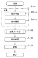
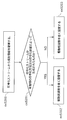
- FIG. 1B is a flowchart showing a characteristic processing flow in the image coding method according to Embodiment 1 of the present invention.
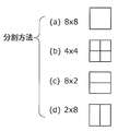
- FIG. 2 is a diagram illustrating an example of a method for dividing a processing target block.
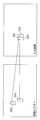
- FIG. 3 is a schematic diagram for explaining motion compensation.
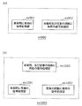
- FIG. 4 is a flowchart showing a flow of boundary filter processing according to Embodiment 1 of the present invention.
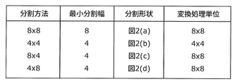
- FIG. 5 is a diagram illustrating an example of a conversion unit corresponding to the division method.
- FIG. 6 is a diagram for explaining the processing target boundary.
- FIG. 7 is a schematic diagram for explaining the characteristics of an image including a processing target boundary.
- FIG. 8 is a diagram for explaining the filter processing.
- FIG. 9A is a block diagram showing a functional configuration of an image decoding apparatus according to Embodiment 2 of the present invention.
- FIG. 9B is a flowchart showing a characteristic processing flow in the image decoding method according to Embodiment 2 of the present invention.
- FIG. 10 is a flowchart showing a flow of boundary filter processing according to Embodiment 2 of the present invention.
- FIG. 11 is a flowchart showing a process flow of the filter target pixel determination method according to the third embodiment of the present invention.
- FIG. 12 is a schematic diagram for explaining an example of the filter processing according to Embodiment 4 of the present invention.
- FIG. 9A is a block diagram showing a functional configuration of an image decoding apparatus according to Embodiment 2 of the present invention.
- FIG. 9B is a flowchart showing a characteristic processing flow in the image decoding method according to Embodiment 2 of the present invention.
- FIG. 10 is
- FIG. 13 is a block diagram showing a functional configuration of an image coding apparatus according to Embodiment 5 of the present invention.
- FIG. 14 is a flowchart showing the operation of the boundary filter section according to Embodiment 5 of the present invention.
- FIG. 15 is a schematic diagram illustrating an example of conversion size candidates of conversion units for the division method.
- FIG. 16 is a flowchart illustrating a process flow of a conversion size determination method.
- FIG. 17 is a block diagram showing a functional configuration of an image decoding apparatus according to Embodiment 6 of the present invention.
- FIG. 18 is a flowchart showing a flow of filter information decoding processing according to Embodiment 6 of the present invention.
- FIG. 19 is a flowchart showing the flow of the decoding process when the filter information includes information on the conversion unit.
- FIG. 20 is a configuration diagram of a code string in the image coding method according to Embodiment 7 of the present invention.
- FIG. 21 is a schematic diagram for explaining an example of a method for describing filter information in a code string.
- FIG. 22 is a block diagram showing a functional configuration of an image coding apparatus according to Embodiment 8 of the present invention.
- FIG. 23 is a block diagram showing a functional configuration of an image decoding apparatus according to Embodiment 9 of the present invention.
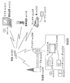
- FIG. 24 is an overall configuration diagram of a content supply system that realizes a content distribution service.
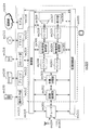
- FIG. 25 is an overall configuration diagram of a digital broadcasting system.
- FIG. 20 is a configuration diagram of a code string in the image coding method according to Embodiment 7 of the present invention.
- FIG. 21 is a schematic diagram for explaining an example of a method for describing filter
- FIG. 26 is a block diagram illustrating a configuration example of a television.
- FIG. 27 is a block diagram illustrating a configuration example of an information reproducing / recording unit that reads and writes information from and on a recording medium that is an optical disk.
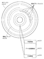
- FIG. 28 is a diagram illustrating a structure example of a recording medium that is an optical disk.
- FIG. 29 is a diagram showing a structure of multiplexed data.
- FIG. 30 is a diagram schematically showing how each stream is multiplexed in the multiplexed data.
- FIG. 31 is a diagram showing in more detail how the video stream is stored in the PES packet sequence.
- FIG. 32 is a diagram showing the structure of TS packets and source packets in multiplexed data.
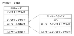
- FIG. 33 is a diagram illustrating a data structure of the PMT.
- FIG. 34 shows the internal structure of multiplexed data information.
- FIG. 35 shows the internal structure of stream attribute information.
- FIG. 36 is a diagram showing steps for identifying video data.
- FIG. 37 is a block diagram illustrating a configuration example of an integrated circuit that realizes the moving picture coding method and the moving picture decoding method according to each embodiment.
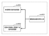
- FIG. 38 is a diagram showing a configuration for switching the drive frequency.
- FIG. 39 is a diagram illustrating steps for identifying video data and switching between driving frequencies.
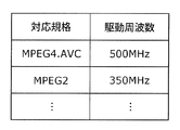
- FIG. 40 is a diagram illustrating an example of a look-up table in which video data standards are associated with drive frequencies.
- FIG. 41A is a diagram illustrating an example of a configuration for sharing a module of a signal processing unit
- FIG. 41B is a diagram illustrating another example of a configuration for sharing a module of a signal processing unit. is there.
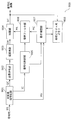
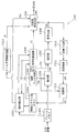
- FIG. 1A is a block diagram showing a functional configuration of an image encoding device 100 according to Embodiment 1 of the present invention.
- the image encoding device 100 encodes an input image for each block to generate an image encoded signal.
- the image encoding device 100 includes a frame memory 101, a motion detection unit 102, a reference picture memory 103, an encoding control unit 104, a boundary filter unit 105, a difference unit 106, A conversion unit 107, a quantization unit 108, a variable length encoding unit 109, an inverse quantization unit 110, an inverse conversion unit 111, and an addition unit 112 are provided.
- the frame memory 101 holds an input image.
- the reference picture memory 103 holds a reconstructed image.
- the frame memory 101 and the reference picture memory 103 may be external memories connected to the image encoding device 100. That is, the image coding apparatus 100 does not necessarily include the frame memory 101 and the reference picture memory 103.
- the image encoding apparatus 100 does not need to include the frame memory 101 and the reference picture memory 103 as separate memories.
- the frame memory 101 and the reference picture memory 103 are configured so as to share one memory. May be.
- the motion detection unit 102 detects a motion vector MV of each prediction unit by performing motion estimation for each prediction unit.
- the prediction unit is an area obtained by dividing the processing target block, and is a processing unit of prediction processing.
- the detected motion vector MV is output to the encoding control unit 104 and the variable length encoding unit 109.
- the encoding control unit 104 generates a motion compensated image of the processing target block as a predicted image by performing motion compensation for each prediction unit based on the detected motion vector. Specifically, the encoding control unit 104 first reads a reference image from the reference picture memory for each prediction unit based on the motion vector of the prediction unit. Then, the encoding control unit 104 generates a motion compensated image by synthesizing the read reference images of each prediction unit.
- a prediction image is generated by the motion detection unit 102 and the encoding control unit 104. That is, the motion detection unit 102 and the encoding control unit 104 generate a prediction image of the processing target block by performing prediction processing for each prediction unit.
- the encoding control unit 104 outputs the generated predicted image (motion compensated image) MC to the boundary filter unit 105. Furthermore, the encoding control unit 104 generates a division method IC for dividing the processing target block to obtain a prediction unit, and outputs the generated division method IC to the variable length encoding unit 109.
- the boundary filter unit 105 detects a boundary located in the conversion unit among the boundaries of the prediction unit by comparing the conversion unit and the prediction unit. Then, the boundary filter unit 105 performs a filtering process on the detected boundary in the generated predicted image.
- the conversion unit is an area obtained by dividing the block to be processed and is a processing unit for frequency conversion processing.
- the filtering process for the boundary is a process for correcting the pixel values of the pixels in the vicinity of the boundary in order to smooth the change in the pixel value in the direction orthogonal to the boundary.
- the boundary filter unit 105 preferably does not perform the filtering process on the boundary of the conversion unit. That is, it is preferable that the boundary filter unit 105 does not perform the filtering process on the boundary that overlaps the boundary of the conversion unit even if it is the boundary of the prediction unit. This is because a deblocking filter is generally performed at the boundary between transform units when generating a reference picture.
- the predicted image PR after the filter processing is output to the difference unit 106 and the addition unit 112.
- the difference unit 106 generates a difference image of the processing target block by calculating a difference between the predicted image after the filtering process and the input image. Specifically, the difference unit 106 calculates the difference value of the pixel value between the prediction image after the filter process and the input image in each pixel of the processing target block, and the difference image having the calculated difference value as the pixel value Is generated.
- the difference image RS is output to the conversion unit 107.
- the conversion unit 107 performs frequency conversion processing of the difference image for each conversion unit.
- the frequency conversion process is, for example, an orthogonal conversion process typified by DCT (Discrete Cosine Transform).
- the transform coefficient generated by the frequency transform process is output to the quantization unit 108.
- the quantization unit 108 generates a quantization coefficient QC by quantizing the conversion coefficient generated by the frequency conversion process.
- the generated quantization coefficient QC is output to the variable length coding unit 109 and the inverse quantization unit 110.
- variable length encoding unit 109 generates an image encoded signal by variable length encoding the quantization coefficient QC, the motion vector MV, and the division method IC.
- the inverse quantization unit 110 inversely quantizes the quantization coefficient generated by the quantization unit 108. Further, the inverse transform unit 111 generates a decoded difference image by performing inverse frequency transform on the result of inverse quantization by the inverse quantization unit 110. Then, the decoded differential image DR generated in this way is output to the adding unit 112.
- the addition unit 112 generates a reconstructed image by adding the decoded difference image and the predicted image.
- the reconstructed image DC generated in this way is output to the reference picture memory 103. That is, the reconstructed image DC is held in the reference picture memory 103 to be used as a reference image when encoding subsequent pictures.
- FIG. 1B is a flowchart showing a characteristic processing flow in the image coding method according to Embodiment 1 of the present invention.
- the input image is held in the frame memory 101 before the flowchart shown in FIG. 1B is started.
- the reference picture memory 103 has already stored decoded images (reconstructed images) of the encoded images, and this reconstructed image is used as a reference picture when the processing target block is encoded.
- the processing target block held in the frame memory 101 is divided into prediction units by a division method instructed by the encoding control unit 104.
- the prediction unit is referred to as a divided region.
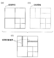
- FIG. 2 is a diagram illustrating an example of a method of dividing a processing target block according to the first embodiment of the present invention.
- the block to be processed is divided into divided regions of 8 ⁇ 8 pixels, 4 ⁇ 4 pixels, 8 ⁇ 2 pixels, or 2 ⁇ 8 pixels. Is done. That is, there are four types of division methods instructed by the encoding control unit 104 as shown in FIGS.
- a prediction image of the processing target block is generated by performing prediction processing for each divided region (step S101).
- This step S101 corresponds to a prediction step.
- the motion detection unit 102 detects a motion vector of each divided region by performing motion estimation for each divided region (step S101a). More specifically, the motion detection unit 102 performs motion detection on the reference picture held in the reference picture memory 103 for each divided region image. In the motion detection, the reference value for which the evaluation value for the image of the divided region is, for example, the smallest within a predetermined range in the reference picture (for example, a rectangular region of ⁇ 32 pixels in the horizontal direction and ⁇ 24 pixels in the vertical direction). A position in the picture is detected. The motion detection unit 102 detects a motion vector from the position thus detected.
- the evaluation value is a value for determining a reference image.
- the evaluation value for example, an absolute value difference sum of pixel values between mutually corresponding pixels can be used.
- a weighted sum of the absolute value difference sum and the code amount of the motion vector can be used.
- the motion detection unit 102 performs motion detection on the image of each divided region for each division method, and detects a motion vector of the divided region. Furthermore, the motion detection unit 102 determines an optimal division method (for example, a division method that minimizes the sum of evaluation values for each divided region when the minimum is used as a reference for the optimum value). Then, the motion detection unit 102 outputs the determined division method to the encoding control unit 104, and outputs a motion vector MV of each divided region divided by the division method to the variable length encoding unit 109. Further, the determined division method and motion vector are transmitted to the encoding control unit 104.
- an optimal division method for example, a division method that minimizes the sum of evaluation values for each divided region when the minimum is used as a reference for the optimum value. Then, the motion detection unit 102 outputs the determined division method to the encoding control unit 104, and outputs a motion vector MV of each divided region divided by the division method to the variable length encoding unit 109. Further,
- the encoding control unit 104 generates a motion compensated image of the processing target block as a predicted image based on the motion vector detected by the motion detecting unit 102 (step S101b). Specifically, the encoding control unit 104 reads a reference image for each divided region from the reference picture memory 103, and generates a predicted image by combining the read reference images. The generated predicted image MC is output to the boundary filter unit 105.
- the encoding control unit 104 acquires the reference image 303 and the reference image 304 from the reference picture, and the processing target block 300 300 prediction images (motion compensation images) are generated.
- the predicted image is processed in units of processing blocks (for example, 16 horizontal pixels and 16 vertical pixels).
- the boundary filter unit 105 performs a filtering process on the boundary of the divided region in the generated predicted image (step S102). The operation of the boundary filter unit 105 will be described in detail with reference to FIGS.
- FIG. 4 is a flowchart showing a flow of boundary filter processing according to Embodiment 1 of the present invention. Specifically, FIG. 4 is a flowchart for explaining the operation when the boundary filter unit 105 performs the filtering process on the predicted image based on the division method acquired from the encoding control unit 104.
- the boundary filter unit 105 acquires the prediction image MC and the division method corresponding to the prediction image MC from the encoding control unit 104 (step S401).
- the boundary filter unit 105 determines whether or not there is a boundary between divided regions in the conversion unit (step S402). That is, the boundary filter unit 105 detects a boundary (hereinafter referred to as a “processing target boundary”) located within the conversion unit among the boundaries of the divided areas by comparing the conversion unit and the divided areas.
- a boundary hereinafter referred to as a “processing target boundary”
- the boundary filter unit 105 acquires the shape information of the divided region based on the division method corresponding to the predicted image MC. Then, for example, as shown in FIG. 5, the boundary filter unit 105 compares the conversion unit determined in advance according to the division method and the divided region, and determines whether there is a boundary of the divided region in the conversion unit. To do.
- FIG. 6A is a diagram illustrating a boundary between conversion units in the processing target block.
- FIG. 6B is a diagram illustrating the boundaries of the divided areas in the processing target block.
- FIG. 6C is a diagram illustrating a processing target boundary detected by comparing a boundary between conversion units and a boundary between divided regions. In FIG. 6C, the processing target boundary is hatched.
- the boundary filter unit 105 compares the minimum division width and the conversion unit for the division method, and the minimum division width is converted. When the length is smaller than one side of the unit, it is determined that the boundary of the divided area of the reference image MC occurs in the conversion unit.
- the filtering process is not performed on the predicted image of the processing target block, and the boundary filtering process ends.
- the boundary filter unit 105 performs a filtering process on the processing target boundary (for example, the processing target boundary shown in FIG. 6C) (step S403).
- the filtering process for the processing target boundary in step S403 will be described in detail.
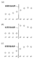
- FIG. 7 is a schematic diagram for explaining the characteristics of an image including a processing target boundary.
- FIG. 7A shows an original image 701, a predicted image 702, and a difference image 706.
- An original image 701 is an image of a processing target block included in an input image held in the frame memory 101.
- the predicted image 702 is an image obtained by performing motion compensation on each of the divided regions 703, 704, and 705.
- the difference image 706 is an image representing a difference between the original image 701 and the predicted image 702.
- the difference image 706 that is a difference signal between the original image 701 and the predicted image 702
- the value of the pixel near the boundary of the divided region is increased.
- FIG. 7B shows a distribution of pixel values in a portion 707 that includes the object boundary and straddles the divided area in the difference image 706.
- FIG. 7C shows a distribution of pixel values in a portion 708 that includes an object boundary similar to that of the portion 707 and does not extend over the divided area.
- the horizontal axis indicates the pixel position in the direction orthogonal to the boundary of the divided areas, and the vertical axis indicates the pixel value.
- FIG. 7B there is a large change in value due to the boundary of the divided area in the central portion, and a gradual change in value due to the object boundary is seen near the right side.
- FIG. 7C only a gradual change in value due to the object boundary is seen near the right side.
- step S402 the boundary filter unit 105 detects the processing target boundary 710 shown in FIG. Then, the boundary filter unit 105 performs filter processing on an image in the vicinity of the processing target boundary 710 in the predicted image 702. That is, the boundary filter unit 105 performs filter processing on the processing target boundary.
- the image to be filtered is not a difference image but a predicted image. This is because when the filter process is performed on the difference image between the input image and the predicted image, it is difficult to restore the component lost by the filter process. For example, if a filter process that replaces the frequency component of a frequency higher than a certain value in the difference image with zero is performed, even if the difference image after the filter process is quantized with a very high accuracy, the high lost by the filter process It becomes difficult to restore the frequency component of the frequency. That is, it is difficult to restore an image close to the input image.
- the purpose of the filtering process here is to smooth steep edges that are not included in the natural image.
- FIG. 8 a description will be given of filter processing performed on pixels adjacent to the processing target boundary.
- FIG. 8 is a diagram for explaining the filter processing.
- FIG. 8 shows pixel values of pixels near the processing target boundary.
- the horizontal axis indicates the position of the pixel in the direction orthogonal to the processing target boundary
- the vertical axis indicates the pixel value.
- the pixel values of the pixel p3, the pixel p2, the pixel p1, the pixel p0, the pixel q0, the pixel q1, the pixel q2, and the pixel q3 are p3, p2, p1, p0, q0, q1, q2, and q3, respectively.
- FIG. 8A shows the pixel value of the input image
- FIG. 8B shows the pixel value of the predicted image
- FIG. 8C shows the pixels near the processing target boundary in FIG. 8B.
- the pixel value of the prediction image after performing a filter process with respect to is shown.
- the predicted image after the filtering process is closer to the input image than the reference image before the filtering process.
- the difference value included in the difference image becomes small, it is possible to perform the conversion process efficiently and to encode efficiently.
- the boundary filter unit 105 performs a filtering process on a pixel near the processing target boundary by a predetermined method for smoothing a change in pixel value. Then, the boundary filter unit 105 outputs the predicted image PR after the filtering process to the difference unit 106 and the addition unit 112.
- the difference unit 106 calculates a difference value between pixel values of corresponding pixels between the input image and the predicted image PR, and generates a residual image RS (step S103).
- This residual image RS corresponds to a difference image.
- the conversion unit 107 performs frequency conversion on the residual image RS (step S104).
- the conversion unit 107 outputs a conversion coefficient obtained by frequency conversion to the quantization unit 108.
- Embodiment 3 a method for determining a neighboring pixel at the boundary to be processed, which is an object of the filtering process, will be described in detail in Embodiment 3, and a filtering method for the neighboring pixel will be described in detail in Embodiment 4.
- the image coding apparatus 100 when coding an input image, converts the input image into a square area and a block (coding unit) that is a processing unit of the coding process. ). Then, the image coding apparatus 100 further divides the block thus divided into a plurality of divided regions by a predetermined division method. Then, the image encoding device 100 generates a predicted image of the processing target block by performing motion detection and motion compensation on each divided region.
- the image encoding apparatus 100 detects, as a processing target boundary, a boundary that does not coincide with a conversion unit that is a processing unit of conversion processing for a differential signal in the subsequent stage, among the boundaries of the divided regions. Then, the image encoding device 100 performs a filtering process on the processing target boundary in the predicted image.
- the filtering process can be performed on the boundary. Therefore, a sudden change in the pixel value occurring at the boundary of the prediction unit can be smoothed, and the value of the difference image between the input image and the prediction image can be reduced. Moreover, since it is not necessary to make the conversion unit small so that there is no boundary of the prediction unit (divided region) in the conversion unit as in the past, it is necessary to increase the conversion unit even when the prediction unit is small. Can do. As a result, the code amount can be greatly reduced, and the encoding efficiency can be improved.
- the filtering process is performed only on the prediction unit boundary located within the conversion unit among the prediction unit boundaries. Therefore, the processing amount can be reduced as compared with the case where the filtering process is performed on all the boundaries of the prediction units. Furthermore, in the decoded image or the reference image, it is possible to suppress the filtering process overlapping with the coding distortion removal filter (deblocking filter) performed on the boundary of the transform unit, and by performing the filtering process a plurality of times. Degradation of image quality (image blur) can be suppressed.
- the division method and conversion unit need not be limited to the division method and conversion unit shown in FIG.
- the image coding method according to the present embodiment is performed on the boundary of the prediction unit located in the transform unit. By performing the filtering process, the same effects as described above can be obtained.
- image coding apparatus 100 performs the filtering process on all the boundaries of the divided areas in the transform unit, but does not necessarily need to perform the filtering process on all.
- the filtering process for the boundary between the two divided areas is as follows. It may be skipped. By doing so, it is possible to reduce the processing amount of the filter processing, to suppress the prediction image from being excessively filtered, and to suppress deterioration in image quality (image blurring) due to the filter processing.
- information indicating that the filtering process is skipped may be described as stream header information. By doing so, it is possible to control ON / OFF of the filter according to the feature of the image, and it is possible to maintain the image quality of the decoded image with high image quality.
- the method for sending the filter header information will be described in detail in another embodiment.
- an in-plane prediction process may be performed instead of the motion detection process (step S101a) and the motion compensation process (step S101b). That is, in the prediction process (step S101), the encoding control unit 104 predicts the intra prediction image of the processing target block by performing intra prediction for each prediction unit based on the reconstructed image of the encoded block. It may be generated as an image. In this case, the image encoding device 100 may not include the motion detection unit 102.
- the image encoding device 100 does not necessarily include all the processing units illustrated in FIG. 1A, and includes, for example, only a processing unit that performs processing of each step included in the image encoding method illustrated in FIG. 1B. Also good.
- FIG. 9A is a block diagram showing a functional configuration of an image decoding apparatus 900 according to Embodiment 2 of the present invention.
- the image decoding apparatus 900 decodes an image encoded signal obtained by encoding the target image to generate a decoded image.
- the image decoding apparatus 900 includes a variable length decoding unit 901, an inverse quantization unit 902, an inverse transformation unit 903, an addition unit 904, a decoding control unit 905, a boundary filter unit 906, and a motion compensation unit 907. And a reference picture memory 908.
- the input code string BS is an image encoded signal generated by the image encoding apparatus 100 according to Embodiment 1 of the present invention. That is, the input code string BS is an image encoded signal obtained by encoding the input image for each block.
- the reference picture memory 908 holds a decoded image that is a decoded image. Note that the reference picture memory 908 may be an external memory connected to the image decoding apparatus 900. That is, the image decoding apparatus 900 does not necessarily include the reference picture memory 908.
- the variable length decoding unit 901 obtains a quantization coefficient, a division method, and a motion vector by performing variable length decoding on the input code string BS.
- the division method is a method for dividing the processing target block into a plurality of prediction units (divided regions).
- the acquired quantization coefficient QC is output to the inverse quantization unit 902, the division method IC is output to the decoding control unit 905, and the motion vector MV is output to the motion compensation unit 907.
- the inverse quantization unit 902 performs inverse quantization on the quantization coefficient. Then, the inverse transform unit 903 generates a decoded difference image by performing inverse frequency transform on the inverse quantization result in the inverse quantization unit 902 for each transform unit. The decoded differential image DR generated in this way is output to the adding unit 904.
- the decoding control unit 905 acquires the division method IC for the processing target block, and outputs it to the boundary filter unit 906 and the motion compensation unit 907.
- the motion compensation unit 907 acquires a division method for dividing the processing target block into prediction units. Furthermore, the motion compensation unit 907 acquires a motion vector for each prediction unit divided according to the acquired division method. Then, the motion compensation unit 907 generates a motion compensated image of the processing target block as a predicted image by performing motion compensation for each prediction unit based on the acquired motion vector. That is, the motion compensation unit 907 generates a prediction image of the processing target block by performing prediction processing for each prediction unit that is an area obtained by dividing the processing target block.
- the motion compensation unit 907 generates a motion compensated image of the processing target block by acquiring a reference image from the reference picture memory 908 based on the division method and the motion vector.
- a motion vector is described for each divided region (prediction unit). Therefore, the motion compensation unit 907 acquires a reference image for each divided region in accordance with the motion vector, and generates a motion compensated image by combining the acquired reference images.
- the motion compensation unit 907 acquires the reference image 303 and the reference image 304 from the reference picture memory 908. Then, the motion compensated image is generated as the predicted image MC. Then, the motion compensation unit 907 outputs the predicted image MC to the boundary filter unit 906.
- the boundary filter unit 906 detects a boundary located within the conversion unit among the boundaries of the prediction unit by comparing the conversion unit and the prediction unit. Then, the boundary filter unit 906 performs filter processing on the detected boundary in the generated predicted image.
- the conversion unit may be determined according to a predetermined correspondence relationship between the prediction unit and the conversion unit, for example.
- the conversion unit may be determined independently of the prediction unit.
- the addition unit 904 generates a decoded image of the processing target block by adding the prediction image after the filtering process and the decoded differential image.
- FIG. 9B is a flowchart showing a characteristic processing flow in the image decoding method according to Embodiment 2 of the present invention.
- decoded picture has already been stored in the reference picture memory 908 before the flowchart shown in FIG. 9B is started.
- This decoded image is used as a reference picture when decoding a code string.
- the inverse transform unit 903 generates a decoded difference image of the processing target block by performing an inverse frequency transform process for each transform unit (step S901).
- the motion compensation unit 907 generates a prediction image of the processing target block by performing prediction processing for each prediction unit that is an area obtained by dividing the processing target block (step S902). Specifically, the motion compensation unit 907 first acquires a motion vector for each prediction unit (step S902a). Subsequently, the motion compensation unit 907 generates a motion compensated image of the processing target block as a predicted image by performing motion compensation for each prediction unit based on the acquired motion vector (step S902b).
- the boundary filter unit 906 performs a filtering process on the boundary of the prediction unit in the generated predicted image (step S903). The operation of the boundary filter unit 906 will be described with reference to FIG.
- FIG. 10 is a flowchart showing the flow of boundary filter processing according to Embodiment 2 of the present invention. Specifically, FIG. 10 is a flowchart for explaining the operation when the boundary filter unit 906 performs the filtering process on the predicted image based on the division method acquired from the decoding control unit 905.
- the boundary filter unit 906 acquires the prediction image of the processing target block from the motion compensation unit 907, and further acquires the division method of the processing target block from the decoding control unit 905 (step S1001).
- the boundary filter unit 906 determines whether or not there is a boundary between the divided areas in the conversion unit (step S1002). That is, the boundary filter unit 105 detects a boundary located within the conversion unit among the boundaries of the divided regions by comparing the conversion unit and the divided regions.
- the boundary filter unit 906 acquires the shape information of the divided area based on the division method. Then, for example, as shown in FIG. 5, the boundary filter unit 906 compares the conversion unit determined in advance according to the division method and the divided region, and determines whether there is a boundary of the divided region in the conversion unit. To do. Since this comparison process is the same as step S402 of the first embodiment, detailed description thereof is omitted.
- step S1002 when the processing target boundary is not detected (NO in step S1002), the filtering process is not performed on the predicted image of the processing target block, and the boundary filtering process ends.
- step S1003 when the processing target boundary is detected (YES in step S1002), the boundary filter unit 906 performs a filtering process on the processing target boundary (for example, the processing target boundary shown in FIG. 6C) (step S1003). Since the filtering process in step S1003 is the same as that in step S403 in the first embodiment, detailed description thereof is omitted.
- the boundary filter unit 105 outputs the predicted image PR after the filter processing to the addition unit 904.
- the adding unit 904 generates a decoded image DC of the processing target block by adding the decoded differential image DR and the predicted image PR after the filter process (step S904).
- the decoded image DC generated in this way is output to the reference picture memory 908. That is, the decoded image DC is an output image and a reference picture used in subsequent decoding.
- the image decoding apparatus 900 performs each processing target when decoding the code string generated by the image encoding method according to Embodiment 1 of the present invention. Get block partition information. Then, the image decoding apparatus 900 performs motion compensation for each prediction unit according to the division information and the motion vector described in the code string or the surrounding motion vector that has already been decoded. A motion compensated image is generated as a predicted image. In the predicted image generated in this way, a filtering process is performed on the boundary of the divided regions located within the prediction unit. Then, the image decoding apparatus 900 generates a decoded image by adding the prediction image after the filter process and the decoded difference image.
- division method and conversion unit need not be limited to the division method and conversion unit shown in FIG.
- the boundary of the divided area is located in the conversion unit, the same effect as described above is obtained.
- the image decoding apparatus 900 performs the filtering process on all the boundaries of the divided areas in the transform unit, as in the first embodiment, but not necessarily all. There is no need to perform filtering. For example, when the motion vectors are the same in two adjacent divided areas, and the reference image is acquired from the adjacent areas in the reference picture, the filtering process for the boundary between the two divided areas is as follows. It may be skipped. By doing so, it is possible to reduce the processing amount of the filter processing, to suppress the prediction image from being excessively filtered, and to suppress deterioration in image quality (image blurring) due to the filter processing.
- the method for determining the neighboring pixels of the boundary to be processed which is the target of the filtering process, will be described in detail in the third embodiment.
- the mode 4 will be described in detail.
- the image decoding apparatus 900 does not necessarily include all the processing units illustrated in FIG. 9A.
- the image decoding device 900 includes only a processing unit that performs processing of each step included in the image decoding method illustrated in FIG. 9B. Also good.
- the part to be filtered is the boundary of the prediction unit (processing target boundary) located within the conversion unit.
- the pixel values of the pixels p3, p2, p1, p0, q0, q1, q2, q3 are p3, p2, p1, p0, q0, q1, q2, q3, respectively.
- FIG. 11 is a flowchart showing a process flow of the filter target pixel determining method according to the third embodiment of the present invention.
- the boundary filter unit 105 or 906 (hereinafter described as a representative of the boundary filter unit 105) acquires filter information indicating ON / OFF of the filter described in the header information of the stream. Then, the boundary filter unit 105 determines whether the filter information is information indicating that the filter is OFF (step S1101).
- the boundary filter unit 105 determines that all the pixels near the processing target boundary are not the filter target pixels (step S1102). On the other hand, when the filter information is information indicating the filter ON (NO in step S1101), the boundary filter unit 105 determines the pixel p0 and the pixel q0 as the filter target pixels (step S1103). Next, the boundary filter unit 105 compares the absolute value of the difference between the pixel values of the pixel p1 and the pixel p0 with a predetermined threshold value TH (step S1104).
- the threshold value TH is, for example, a value given by (Expression 1).
- QP is a quantization parameter representing quantization accuracy. Offset is described in the file header information as an adjustment parameter.
- the threshold value TH need only be determined so as to increase as the quantization parameter QP increases, and does not necessarily have to be determined according to (Equation 1).
- the threshold TH may be described in the file header information.
- the boundary filter unit 105 determines the pixel p1 as a filter target pixel (step S1105). On the other hand, if the absolute value of the difference is greater than or equal to the threshold value TH (NO in step S1104), the process proceeds to next step S1106.
- the boundary filter unit 105 compares the absolute value of the difference between the pixel values of the pixel q1 and the pixel q0 with the threshold value TH as in step S1104 (step S1106).
- the threshold TH is the same value as in step S1104.
- the boundary filter unit 105 further determines the pixel q1 as a filter target pixel (step S1107), and ends the filter target pixel determination process. .
- the filter target pixel determination process is terminated.
- the threshold value TH is a value that varies depending on the quantization parameter QP shown in (Equation 1) as an example, but varies depending on the difference in motion vectors between prediction units adjacent to the processing target boundary. It may be a value.
- the threshold value TH may be determined to increase as the sum MVD of the absolute value of the difference between the X components of the motion vector and the absolute value of the difference between the Y components increases.
- the difference in motion vectors is large, the change in image characteristics at the processing target boundary is considered to be different. Therefore, by changing the threshold value TH depending on the difference between the motion vectors, it is possible to determine the filter target pixel in accordance with the characteristics of the image.
- the threshold value TH may be determined so as to change depending on both the MVD and the quantization parameter QP.
- the filter target pixel is determined by the above method.
- the boundary filter unit 105 determines whether or not only the pixels p0, p1, q0, and q1 are determined as filter target pixels, but may further determine the pixels p2 and q2. Good. In that case, the boundary filter unit 105 compares the absolute value of the difference (for example,
- the absolute value of the difference for example,
- a threshold value on the assumption that the adjacent pixel is the filtering target pixel for example, p1
- the filter information indicating ON / OFF of the filter is described in the header information of the stream has been described in step S1101, such filter information is not necessarily described in the header information.
- the filter information may not be described in the header information. In this case, header information can be reduced.
- filter information indicating the number of boundary pixels may be described in the header information.
- the boundary filter unit 105 may determine the filter target pixel according to the number of pixels indicated by the filter information. For example, when the number of pixels is 1, the boundary filter unit 105 may determine the pixels p0 and q0 as filter target pixels. For example, when the number of pixels is 2, the boundary filter unit 105 may determine the pixels p1, p0, q0, and q1 as filter target pixels. Thereby, the processing amount of the boundary filter unit 105 can be significantly reduced.
- the filter processing will be described using pixel indexes p3, p2, p1, p0, q0, q1, q2, q3 arranged in a line in the filter processing direction shown in FIG.
- the pixel values of the pixels p3, p2, p1, p0, q0, q1, q2, q3 are p3, p2, p1, p0, q0, q1, q2, q3, respectively.
- FIG. 12 is a schematic diagram for explaining an example of the filter processing according to Embodiment 4 of the present invention.
- a processing target block 1200 is divided into a divided area 1201 and a divided area 1202 each having 4 horizontal pixels and 8 vertical pixels.
- the processing target block 1200 is a conversion unit, and the divided area 1201 and the divided area 1202 are prediction units.
- the encoding control unit 104 acquires the reference image 1203 and the reference image 1204 from the reference picture memory 103. Then, the encoding control unit 104 combines the reference image 1203 and the reference image 1204 to generate a predicted image (motion compensation image) of the processing target block.
- the boundary filter unit 105 uses a reference image region 1205 adjacent to the reference image 1203 and a reference image region 1206 adjacent to the reference image 1204. And filter processing. For example, the boundary filter unit 105 determines an average value obtained by calculating an overlapping region (a portion indicated by cross hatching in the processing target block 1200) in units of pixels as a pixel value after filtering.
- the boundary filter unit 105 determines the pixel value of the pixel adjacent to the processing target boundary by calculating the average value of the two reference images. However, the boundary filter unit 105 may perform filter processing as shown in (Expression 2).
- the filter coefficients d0, d1, and d2 may be set to values close to 0.5.
- the boundary filter unit 105 may perform filter processing by shifting down and shifting up according to (Expression 3) obtained by modifying (Expression 2).
- the filtering process is performed according to (Equation 3)
- the information amount of the header information can be reduced, and the processing amount of the filtering process can be reduced.
- the boundary filter unit 105 can perform the filtering process on the determined filter target pixel by the method described above. Note that the boundary filter unit 105 can reduce memory access by acquiring an image of an area larger than the divided area (prediction unit) when acquiring the reference image from the reference picture memory 103.
- boundary filter unit 105 may perform the filtering process by a method different from the above.
- the boundary filter unit 105 may perform a filter process according to (Equation 4), for example.
- the pixel values after the filter processing of the pixel q1, the pixel q0, the pixel p0, and the pixel p1 are represented as q′1, q′0, p′0, and p′1, respectively.
- c 0,0 , c 0,1 , c 0,2 , c 0,3 , c 1,0 , c 1,1 , c 1,2 , c 1,3 are filter coefficients, for example, It is represented by (Formula 5).
- the filter processing realized by the filter coefficient of (Equation 5) smoothes the change of the pixel value at the processing target boundary as in the image of FIG.
- the filter coefficient is not limited to (Equation 5), and a simplified value such as (Equation 6) may be set.
- the filtering target pixel has been described here, the pixel whose distance from the processing target boundary is up to three pixels is also the filtering target pixel.
- a code indicating a filter type and a filter coefficient or a filter strength may be described in the header information. In this way, steep edges that do not exist in the natural image in the conversion unit can be removed. As a result, since the predicted image can be brought close to the input image, the difference image can be efficiently converted by the conversion process, and the code amount can be reduced.
- the image encoding apparatus determines an optimum filter processing method from among a plurality of filter processing methods, and describes filter information indicating the determined filter processing method in the image encoded signal. .
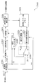
- FIG. 13 is a block diagram showing a functional configuration of an image coding apparatus according to Embodiment 5 of the present invention.
- the image encoding device 1300 includes a frame memory 1301, a motion detection unit 1302, a reference picture memory 1303, an encoding control unit 1304, a boundary filter unit 1305, a difference unit 1306, A conversion unit 1307, a quantization unit 1308, a variable length coding unit 1309, an inverse quantization unit 1310, an inverse conversion unit 1311, an addition unit 1312, and a filter information description unit 1313 are provided.
- the image encoding device 1300 includes a filter information description unit 1313 in addition to the components included in the image encoding device 100 of FIG.
- processing blocks common to the image coding apparatus 100 the processing blocks excluding the boundary filter unit 1305 and the variable length coding unit 1309 operate in the same manner as in the first embodiment, and thus description thereof is omitted.
- FIG. 14 is a flowchart for explaining an operation when the boundary filter unit 1305 performs the filter process on the predicted image MC based on the division method.
- the boundary filter unit 1305 acquires the predicted image MC and the division method corresponding to the predicted image MC from the encoding control unit 1304 (step S1401).
- the boundary filter unit 1305 determines whether or not there is a boundary of the divided areas in the conversion unit (step S1402). That is, the boundary filter unit 1305 detects a boundary located within the conversion unit among the boundaries of the divided regions by comparing the conversion unit and the divided regions.
- the boundary filter unit 1305 acquires the shape information of the divided region based on the division method corresponding to the predicted image MC. For example, as shown in FIG. 5, the boundary filter unit 1305 compares the conversion unit determined in advance according to the division method and the divided region, and the boundary of the divided region (processing target boundary) is included in the conversion unit. Determine if it exists. Note that the processing in step S1402 is the same as the processing in step S402 described in the first embodiment, and thus detailed description thereof is omitted.
- step S1402 when the processing target boundary is not detected (NO in step S1402), the filtering process is not performed on the predicted image of the processing target block, and the boundary filtering process ends.
- the boundary filter unit 1305 performs filtering processing of a plurality of methods for the processing target boundary (for example, the processing target boundary illustrated in FIG. 6C).
- the evaluation value is calculated (step S1403).
- the boundary filter unit 1305 obtains an evaluation value for each filtering method described in the fourth embodiment.
- Filtering methods include, for example, no filter, filter processing (coefficient (0.5, 0.7, 0.825)) of (expression 2), and filter processing (coefficient (0.5, 0) of (expression 2)). , 5, 0.5)) and (Formula 5). This combination of methods is an example, and for example, more method combinations may be used.
- the evaluation value it is possible to use a weighted sum of the sum of absolute differences between the predicted image after filtering and the input image, the filtering method, and the code amount of the filter coefficient. In this case, the smaller the evaluation value, the higher the evaluation.
- the evaluation value may be a sum of values after conversion processing (for example, conversion used in encoding or Hadamard conversion). Thereby, the effect of a filter can be evaluated further appropriately.
- the boundary filter unit 1305 determines a filtering method (method and coefficient) having the highest evaluation value (here, the lowest evaluation value) from among a plurality of filtering methods. Then, the boundary filter unit 1305 outputs filter information indicating the determined filter processing method to the filter information description unit 1313 (step S1404).
- the boundary filter unit 1305 adds the motion compensation image (predicted image PR) as it is without performing the filter processing. Output to the unit 1312 and the difference unit 1306.
- the boundary filter unit 1305 performs the filter process on the processing target boundary based on the method determined in step S1404 (step S1406).
- the predicted image PR is output to the addition unit 1312 and the difference unit 1306.
- the filter information description unit 1313 outputs the filter information obtained from the boundary filter unit 1305 to the variable length coding unit 1309 as filter header information.
- the operation of the filter information description unit 1313 and the description method of the filter header information will be described in detail in another embodiment.
- a filter processing method with a high filter effect can be determined from among a plurality of filter processing methods. Then, according to the filtering method determined as described above, the filtering process can be performed on the boundary of the prediction unit located in the conversion unit. As a result, the difference between the input image and the predicted image can be further reduced, and the code amount can be reduced.
- the boundary filter unit 1305 has calculated the evaluation values for all combinations of the filtering method, but when the evaluation value falls below a predetermined threshold, the calculation of the subsequent evaluation values is stopped.
- the filtering method may be determined as the optimum filtering method. By doing in this way, the processing amount for determining the filter processing method can be reduced.
- the conversion unit TU by passing the conversion unit TU between the boundary filter unit 1305 and the conversion unit 1307, the conversion unit can be changed in consideration of the presence or absence of the boundary filter processing.
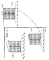
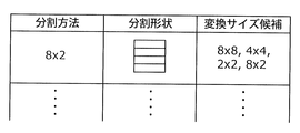
- FIG. 15 is a diagram illustrating an example of conversion size candidates of conversion units for the division method.
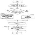
- FIG. 16 is a flowchart showing the flow of processing of the conversion size determination method.
- the boundary filter unit 1305 determines, in order with respect to the conversion size shown in FIG. 15, whether the boundary of the divided region (prediction unit) indicated in the division method is within the conversion unit (step S1601). For example, in the case of a conversion size of 8 ⁇ 8, three boundaries in the horizontal direction are detected as processing target boundaries, and it is determined that there is a boundary between divided areas in the conversion unit.
- the boundary filter unit 1305 determines a filter processing method that provides an optimum evaluation value by the method illustrated in FIG.
- the processing method and the evaluation value are held (step S1602).
- the boundary filter unit 1305 may determine a filtering method based on the sum of the evaluation values of the three boundaries.
- the boundary filter unit 1305 calculates and holds the evaluation value (step S1603). For example, in the case of the conversion size 2 ⁇ 2, since there is no boundary between the divided areas in the conversion unit, the evaluation value for the conversion size 2 ⁇ 2 is calculated. In this case as well, the same evaluation value calculation method (the absolute difference sum or the weighted sum of the conversion value information and the code amount of the filter information) can be used.
- the boundary filter unit 1305 determines the conversion size of the conversion unit and the filter processing method based on the evaluation values (step S1604).
- the determined conversion size is output to the filter information description unit 1313 together with the filter information, and is described in the code string as the header information of the stream.
- the division method, the conversion size, and the filtering method can be determined so that the difference between the input image and the predicted image after the filtering process becomes smaller.
- the boundary filter unit 1305 calculates the evaluation values for all combinations of the conversion sizes. However, when the boundary filter unit 1305 falls below a predetermined threshold, the calculation of the subsequent evaluation values is stopped, and the conversion size at that time is converted to the optimal conversion size. The size may be determined. In this way, the processing amount can be reduced.
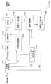
- FIG. 17 is a block diagram showing a functional configuration of an image decoding apparatus according to Embodiment 6 of the present invention.
- This image decoding apparatus 1700 decodes the code string generated by the image encoding apparatus 1300 according to Embodiment 5.
- the image decoding apparatus 1700 includes a variable length decoding unit 1701, an inverse quantization unit 1702, an inverse transform unit 1703, an addition unit 1704, a decoding control unit 1705, a boundary filter unit 1706, and a motion compensation unit 1707.
- the image decoding apparatus 1700 according to the present embodiment has a configuration in which a filter information decoding unit 1709 is added to the image decoding apparatus 900 according to the second embodiment, and includes a decoding control unit 1705 and a boundary filter unit 1706. All operations are the same except for the operation.
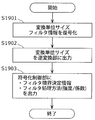
- FIG. 18 is a flowchart showing a flow of filter information decoding processing according to Embodiment 6 of the present invention.
- the filter information decoding unit 1709 acquires the code sequence of the filter information from the variable length decoding unit 1701 and decodes it (step S1801).
- the filter information decoding unit 1709 obtains the filter boundary determination information (the offset value or threshold value or the number of boundary pixels for deriving the threshold value for determining the filter boundary) and the filter processing method and intensity obtained by decoding.
- the coefficient is output to the decoding control unit 1705 (step S1802).
- the decoding control unit 1705 outputs the obtained information for determining the filter boundary to the boundary filter unit 1706, and when the filter processing method is expressed by (Equation 2), the image from the motion compensation unit is output. Change the acquisition method.
- the code string generated by the image coding method of Embodiment 5 can be correctly decoded.
- FIG. 19 shows an operation flow when the image encoding method describes the conversion unit size (conversion size) in the code string.
- the filter information decoding unit 1709 acquires the filter information and the conversion unit size code string from the variable length decoding unit 1701, and decodes the conversion unit size and the filter information (step S1901).
- the filter information decoding unit 1709 outputs the transform unit size obtained by decoding to the decoding control unit 1705.
- the decryption control unit 1705 outputs the transform unit size to the inverse transform unit 1703 (step S1902).
- the filter information decoding unit 1709 outputs the filter boundary determination information and the filter processing method (coefficient or intensity) obtained by decoding to the decoding control unit 1705 (S1903).
- the code string can be correctly decoded by the decoding method of the present invention.
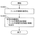
- Embodiment 7 a method for coding and decoding by describing filter header information FltStr indicating information for filter determination, conversion unit size for filter processing, and the like as stream header information will be described. .
- FIG. 20 is a configuration diagram of the code string BS in the image coding method according to Embodiment 7 of the present invention.
- FIG. 20A shows an encoded signal corresponding to a moving image sequence composed of at least one screen. This encoded signal is composed of sequence data SeqData, which is data of the entire screen, and a sequence header SeqHdr, which is data common to all data of the entire screen.
- the filter header information FltStr is information including information for determining a filter, a conversion unit size for filter processing, and the like.
- the filter header information FltStr is an OFFSET value used for calculation of a threshold value for filter determination, a threshold value TH, or the number of neighboring pixels from the processing target boundary as information for filter determination.
- the information for filtering may include a filtering method and a filter coefficient or filter strength number.
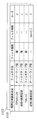
- the table 2101, 2102, etc. may be switched according to the conversion unit size as shown in FIG. 21, and a code number representing a combination of these information may be sent.
- the overlap type of the filter method is processed by the calculation formula shown in (Formula 2)
- the filter tap type is processed by the calculation formula shown in (Formula 4).
- the size of the conversion unit is used for switching the table, but the present invention is not limited to this.
- the sequence header includes filter header information FltStr.
- FIG. 20B shows the structure of the sequence data SeqData.
- the sequence data SeqData includes a picture signal PicStr that is an encoded signal of a picture corresponding to one screen.
- FIG. 20C shows the structure of the picture signal PicStr.
- the picture signal PicStr is composed of picture data PicData which is data of one screen and a picture header PicHdr which is data common to the entire screen.
- the picture header PicHdr includes filter header information FltStr.
- FIG. 20D shows the structure of the picture data PicData.
- the picture data PicData includes a slice signal SliceStr that is an encoded signal of a slice configured by a set of a plurality of block units.
- FIG. 20 (e) shows the structure of the slice signal SliceStr.
- the slice signal SliceStr is composed of slice data SliceData that is data of one slice and a slice header SliceHdr that is data common to all data of one slice.
- FltStr filter header information
- the filter header information FltStr is included only in some picture headers PicHdr instead of including the filter header information FltStr in all the picture headers PicHdr. It may be included.
- filter header information FltStr is included only in some slice headers SliceHdr instead of including the filter header information FltStr in all slice headers SliceHdr. You may be made to do. If the content of the filter header information FltStr is common to each slice, as shown in FIG.
- the header part and the data part other than the header may be separated and transmitted separately.
- the header part and the data part do not become one bit stream as shown in FIG.
- the header part corresponding to the data part is only transmitted in a packet different from the data part, and one bit Even if it is not a stream, the concept is the same as that of the bit stream described with reference to FIG.
- the code string BS encoded by the above method is decoded by the following procedure.
- filter header information FltStr included in the sequence header SeqHdr is acquired, and each information is held.
- filter header information FltStr included in the picture header PicHdr is acquired, and each information is updated.
- the information included in the sequence header SeqHdr is held as it is.
- filter header information FltStr included in the slice header SliceHdr is acquired, and each information is updated.
- FIG. 22 is a block diagram showing a functional configuration of an image coding apparatus according to Embodiment 8 of the present invention.
- the image encoding device 2200 includes a difference unit 2201, a transform / quantization unit 2202, an inverse quantization / inverse transform unit 2203, an addition unit 2204, an encoding distortion removal unit 2205, A reference picture memory 2206, an in-plane prediction unit 2207, a motion compensation prediction unit 2208, a motion detection unit 2209, a switch 2210, a variable length coding unit 2211, and a boundary filter unit 2212 are provided.
- the reference picture memory 2206 may be configured in the form of an external memory connected to the image encoding device 2200.
- the input image is input to the image encoding device 2200. It is assumed that a decoded picture (reconstructed picture) of a coded picture has already been stored in the reference picture memory 2206, and this is used as a reference picture when an input picture is coded.
- the difference unit 2201 is the difference unit 106
- the transformation / quantization unit 2202 is the transformation unit 107 and the quantization unit 108
- the inverse quantization / inverse transformation unit 2203 is the inverse quantization unit 110
- the inverse transformation unit 111 and the addition unit 2204.
- the adder 112 the reference picture memory 2206 operate in the same manner as the reference picture memory 103
- the boundary filter unit 2212 operates in the same manner as the boundary filter unit 105
- the motion detector 2209 operates in the same manner as the motion detector 102.
- the motion compensation prediction unit 2208, the in-plane prediction unit 2207, and the switch 2210 operate in the same manner as the encoding control unit 104 when generating a motion compensated image as the predicted image MC.
- the difference unit 2201 generates a difference image between a predicted image PR and an input image generated by a method to be described later, and outputs the generated difference image to the transform / quantization unit 2202.
- the transform / quantization unit 2202 generates a quantized signal QD by performing conversion and quantization processing on the input difference image, and the generated quantized signal QD is variable with the inverse quantization / inverse transform unit 2203.
- the data is output to the long encoding unit 2211.
- the inverse quantization / inverse transform unit 2203 performs inverse quantization / inverse transform processing on the input quantized signal QD to generate a decoded difference image, and outputs the generated decoded difference image to the adder 2204 To do.
- the adding unit 2204 generates a reconstructed image by adding the decoded difference image acquired from the inverse quantization / inverse transform unit 2203 and the predicted image PR, and sends the generated reconstructed image to the encoding distortion removing unit 2205. Output.
- the coding distortion removal unit 2205 performs a process of applying coding distortion removal (deblocking filter) to the transform unit boundary (for example, the filter indicated by (Equation 4) is processed on the transform unit boundary. Etc.). Note that the encoding distortion removing unit 2205 can omit the process.
- the generation of the predicted image MC is roughly classified into motion compensation prediction and in-plane prediction, and is switched by a switch 2210.
- the in-plane prediction unit 2207 acquires a reference picture from the reference picture memory 2206. Then, the in-plane prediction unit 2207 performs in-plane prediction by a predetermined method (for example, stretching adjacent pixels in the horizontal or vertical direction) based on the acquired reference picture, thereby An in-plane prediction image is generated and output to “a” of the switch 2210. When “a” is selected by the switch 2210, the in-plane prediction image is output to the boundary filter unit 2212 as the prediction image MC. Further, the in-plane prediction division method is output to the boundary filter unit 2212. The boundary filter unit 2212 detects the boundary as a processing target boundary when the boundary of the divided region for in-plane prediction is within the conversion unit, and performs filtering on the boundary.
- a predetermined method for example, stretching adjacent pixels in the horizontal or vertical direction
- the motion detection unit 2209 detects an area corresponding to the prediction unit included in the processing target block from the reference picture. Then, the motion detection unit 2209 outputs a motion vector MV indicating the position of the detected region to the motion compensation prediction unit 2208 and the variable length coding unit 2211. As a method for detecting the region, a sum of differences between the input image and the detection target image in the reference picture, a weighted sum of the motion vector MV, and the like can be used.
- the motion detection unit 2209 The position of the area having the smallest value is searched from the search areas (for example, horizontal 32 pixels, vertical 16 pixels) in a predetermined reference picture, and a motion vector MV indicating the position of the searched area is output. That's fine.
- the motion compensation prediction unit 2208 extracts an image in the reference picture indicated by the acquired motion vector MV for each prediction unit, and outputs it to the “b” of the switch 2210 as a motion compensated image of the processing target block.
- the motion compensated image is output to the boundary filter unit 2212 as the predicted image MC. Further, the motion compensation division method is output to the boundary filter unit 2212. In this case, the boundary filter unit 2212 operates as in the other embodiments.
- Switch 2210 switches whether to output an in-plane prediction image or a motion compensation image as prediction image MC by a predetermined method. That is, the switch 2210 selects one of the in-plane prediction image and the motion compensation image as the prediction image MC. For example, the switch 2210 may compare the difference sum between the input image and the in-plane prediction image and the difference sum between the input image and the motion compensation image, and output the image with the smaller difference sum as the prediction image MC. .
- Information on the generation method of the predicted image PR is output to the variable length coding unit 2211 as the predicted image generation information CI.
- the boundary filter unit 2212 may output the filter information to the variable length encoding unit 2211 together with the predicted image generation information CI.
- variable length encoding unit 2211 performs variable length encoding processing on the quantized signal QD, the motion vector MV, and the predicted image generation information CI, and outputs the result as a code string BS.
- the filtering process for the boundary of the prediction unit located in the conversion unit described in the first embodiment can be realized in the in-plane prediction.
- the difference signal can be reduced and the code amount can be reduced even during in-plane prediction.
- the image coding apparatus 2200 includes both the in-plane prediction unit 2207 and the motion compensation prediction unit 2208, but may include only the in-plane prediction unit 2207. In this case, the motion detection unit 2209 and the switch 2210 are not necessary.
- Embodiment 9 of the present invention describes an image decoding method for performing filtering on a boundary of a prediction unit in the case of a prediction unit boundary in a transform unit, as in the case of a motion compensated image. To do.
- FIG. 23 is a block diagram showing a functional configuration of an image decoding apparatus according to Embodiment 9 of the present invention.
- the image decoding apparatus 2300 includes a variable length decoding unit 2301, an inverse quantization / inverse conversion unit 2302, an addition unit 2303, a coding distortion removal unit 2304, and a reference picture memory 2305.
- the reference picture memory 2305 may be configured in the form of an external memory connected to the image decoding apparatus 2300.
- the inverse quantization / inverse transformation unit 2302 is the same as the inverse quantization unit 902 and inverse transformation unit 903, the addition unit 2303 is the addition unit 904, the reference picture memory 2305 is the reference picture memory 908, and the boundary filter unit 906 is the same.
- the motion compensation unit 907 is expressed as a motion compensation prediction unit 2307 and a reference picture memory 2305
- the decoding control unit 905 is expressed as a motion compensation prediction unit 2307, an in-plane prediction unit 2306, and a switch 2308.
- the code string BS is input to the image decoding device 2300.
- the variable length decoding unit 2301 performs variable length decoding on the code string BS, and obtains predicted image generation information CI, motion information MV, and a quantized signal QD. Then, the variable length decoding unit 2301 outputs the predicted image generation information CI to the switch 2308 and the boundary filter unit 2309, outputs the motion information MV to the motion compensation prediction unit 2307, and dequantizes / inverses the quantized signal QD.
- the data is output to the conversion unit 2302.
- the inverse quantization / inverse transformation unit 2302 performs inverse quantization / inverse transformation processing on the quantized signal QD to generate a decoded difference image, and outputs the decoded difference image to the addition unit 2303.
- the adding unit 2303 adds the decoded difference image and a predicted image PR described later, and outputs the result to the coding distortion removing unit 2304.
- the coding distortion removal unit 2304 performs coding distortion removal processing on the input signal and outputs it to the reference picture memory 2305 as a decoded image.
- the coding distortion removal unit 2304 applies a process (for example, (Equation 4)) for applying coding distortion removal (deblocking filter) to the boundary between transform units, with respect to the boundary between transform units. Etc.) and can be omitted.
- the prediction image generation method is based on the reference picture acquired from the reference picture memory 2305 on the basis of the prediction picture generation information CI, as in the case of the image coding apparatus described in Embodiment 8, and is based on the prediction picture generation information CI. It is generated by the unit 2306 or the motion information MV and the motion compensation prediction unit 2307. The generated image is output to the boundary filter unit 2309 and is subjected to filter processing on the predicted image boundary in the conversion processing unit.
- the filter information is encoded with respect to the code string, it is decoded by the variable length decoding unit 2301, and is input to the boundary filter unit 2309 together with the predicted image generation information CI. Based on the filter information Apply filtering.
- the storage medium may be any medium that can record a program, such as a magnetic disk, an optical disk, a magneto-optical disk, an IC card, and a semiconductor memory.
- FIG. 24 is a diagram showing an overall configuration of a content supply system ex100 that realizes a content distribution service.
- the communication service providing area is divided into desired sizes, and base stations ex106, ex107, ex108, ex109, and ex110, which are fixed wireless stations, are installed in each cell.
- the content supply system ex100 includes a computer ex111, a PDA (Personal Digital Assistant) ex112, a camera ex113, a mobile phone ex114, a game machine ex115 via the Internet ex101, the Internet service provider ex102, the telephone network ex104, and the base stations ex106 to ex110. Etc. are connected.
- PDA Personal Digital Assistant
- each device may be directly connected to the telephone network ex104 without going through the base stations ex106 to ex110 which are fixed wireless stations.
- the devices may be directly connected to each other via short-range wireless or the like.
- the camera ex113 is a device that can shoot moving images such as a digital video camera
- the camera ex116 is a device that can shoot still images and movies such as a digital camera.
- the mobile phone ex114 is a GSM (Global System for Mobile Communications) method, a CDMA (Code Division Multiple Access) method, a W-CDMA (Wideband-Code Division Multiple Access L (Semiconductor Access) method, a W-CDMA (Wideband-Code Division Multiple Access L method, or a high access rate).
- GSM Global System for Mobile Communications
- CDMA Code Division Multiple Access
- W-CDMA Wideband-Code Division Multiple Access L (Semiconductor Access) method
- W-CDMA Wideband-Code Division Multiple Access L method
- a high access rate A High Speed Packet Access
- PHS Personal Handyphone System
- the camera ex113 and the like are connected to the streaming server ex103 through the base station ex109 and the telephone network ex104, thereby enabling live distribution and the like.
- live distribution the content (for example, music live video) captured by the user using the camera ex113 is encoded as described in the above embodiments, and transmitted to the streaming server ex103.
- the streaming server ex103 streams the content data transmitted to the requested client.
- the client include a computer ex111, a PDA ex112, a camera ex113, a mobile phone ex114, a game machine ex115, and the like that can decode the encoded data.
- Each device that receives the distributed data decodes the received data and reproduces it.
- the encoded processing of the captured data may be performed by the camera ex113, the streaming server ex103 that performs the data transmission processing, or may be performed in a shared manner.
- the decryption processing of the distributed data may be performed by the client, the streaming server ex103, or may be performed in a shared manner.
- still images and / or moving image data captured by the camera ex116 may be transmitted to the streaming server ex103 via the computer ex111.
- the encoding process in this case may be performed by any of the camera ex116, the computer ex111, and the streaming server ex103, or may be performed in a shared manner.
- encoding / decoding processes are generally performed by the computer ex111 and the LSI ex500 included in each device.
- the LSI ex500 may be configured as a single chip or a plurality of chips.
- moving image encoding / decoding software is incorporated into some recording media (CD-ROM, flexible disk, hard disk, etc.) that can be read by the computer ex111 and the like, and encoding / decoding processing is performed using the software. May be.
- moving image data acquired by the camera may be transmitted.
- the moving image data at this time is data encoded by the LSI ex500 included in the mobile phone ex114.
- the streaming server ex103 may be a plurality of servers or a plurality of computers, and may process, record, and distribute data in a distributed manner.
- the encoded data can be received and reproduced by the client.
- the information transmitted by the user can be received, decrypted and reproduced by the client in real time, and even a user who does not have special rights or facilities can realize personal broadcasting.
- At least one of the image encoding device and the image decoding device according to each of the above embodiments may be incorporated in the digital broadcasting system ex200. it can.
- the broadcast station ex201 multiplexed data obtained by multiplexing music data and the like on video data is transmitted to a communication or satellite ex202 via radio waves.
- This video data is data encoded by the image encoding method described in the above embodiments.
- the broadcasting satellite ex202 transmits a radio wave for broadcasting, and the home antenna ex204 capable of receiving the satellite broadcast receives the radio wave.
- the received multiplexed data is decoded and reproduced by a device such as the television (receiver) ex300 or the set top box (STB) ex217.
- a reader / recorder ex218 that reads and decodes multiplexed data recorded on a recording medium ex215 such as a DVD or a BD, or encodes a video signal on the recording medium ex215 and, in some cases, multiplexes and writes it with a music signal. It is possible to mount the image decoding apparatus or the image encoding apparatus described in the above embodiments. In this case, the reproduced video signal is displayed on the monitor ex219, and the video signal can be reproduced in another device or system by the recording medium ex215 on which the multiplexed data is recorded.
- an image decoding device may be mounted in a set-top box ex217 connected to a cable ex203 for cable television or an antenna ex204 for satellite / terrestrial broadcasting, and this may be displayed on a monitor ex219 of the television.
- the image decoding apparatus may be incorporated in the television instead of the set top box.
- FIG. 26 is a diagram illustrating a television (receiver) ex300 that uses the image decoding method and the image encoding method described in the above embodiments.
- the television ex300 obtains or outputs multiplexed data in which audio data is multiplexed with video data via the antenna ex204 or the cable ex203 that receives the broadcast, and demodulates the received multiplexed data.
- the modulation / demodulation unit ex302 that modulates multiplexed data to be transmitted to the outside, and the demodulated multiplexed data is separated into video data and audio data, or the video data and audio data encoded by the signal processing unit ex306 Is provided with a multiplexing / demultiplexing unit ex303.
- the television ex300 decodes each of the audio data and the video data, or encodes the respective information, the audio signal processing unit ex304, the signal processing unit ex306 including the video signal processing unit ex305, and the decoded audio signal.
- the television ex300 includes an interface unit ex317 including an operation input unit ex312 that receives an input of a user operation.
- the television ex300 includes a control unit ex310 that controls each unit in an integrated manner, and a power supply circuit unit ex311 that supplies power to each unit.
- the interface unit ex317 includes a bridge ex313 connected to an external device such as a reader / recorder ex218, a recording unit ex216 such as an SD card, and an external recording such as a hard disk.
- a driver ex315 for connecting to a medium, a modem ex316 for connecting to a telephone network, and the like may be included.
- the recording medium ex216 is capable of electrically recording information by using a nonvolatile / volatile semiconductor memory element to be stored.
- Each part of the television ex300 is connected to each other via a synchronous bus.
- the television ex300 receives a user operation from the remote controller ex220 or the like, and demultiplexes the multiplexed data demodulated by the modulation / demodulation unit ex302 by the multiplexing / demultiplexing unit ex303 based on the control of the control unit ex310 having a CPU or the like. Furthermore, in the television ex300, the separated audio data is decoded by the audio signal processing unit ex304, and the separated video data is decoded by the video signal processing unit ex305 using the decoding method described in the above embodiments.
- the decoded audio signal and video signal are output from the output unit ex309 to the outside.
- these signals may be temporarily stored in the buffers ex318, ex319, etc. so that the audio signal and the video signal are reproduced in synchronization.
- the television ex300 may read multiplexed data from recording media ex215 and ex216 such as a magnetic / optical disk and an SD card, not from broadcasting. Next, a configuration in which the television ex300 encodes an audio signal or a video signal and transmits the signal to the outside or writes it to a recording medium will be described.
- the television ex300 receives a user operation from the remote controller ex220 or the like, and encodes an audio signal with the audio signal processing unit ex304 based on the control of the control unit ex310, and converts the video signal with the video signal processing unit ex305. Encoding is performed using the encoding method described in (1).
- the encoded audio signal and video signal are multiplexed by the multiplexing / demultiplexing unit ex303 and output to the outside. When multiplexing, these signals may be temporarily stored in the buffers ex320 and ex321 so that the audio signal and the video signal are synchronized.
- a plurality of buffers ex318, ex319, ex320, and ex321 may be provided as illustrated, or a configuration in which one or more buffers are shared may be employed.
- data may be stored in the buffer as a buffer material that prevents system overflow and underflow, for example, between the modulation / demodulation unit ex302 and the multiplexing / demultiplexing unit ex303.
- the television ex300 has a configuration for receiving AV input of a microphone and a camera, and performs encoding processing on the data acquired from them. Also good.
- the television ex300 has been described as a configuration that can perform the above-described encoding processing, multiplexing, and external output, but these processing cannot be performed, and only the above-described reception, decoding processing, and external output are possible. It may be a configuration.
- the decoding process or the encoding process may be performed by either the television ex300 or the reader / recorder ex218,
- the reader / recorder ex218 may be shared with each other.
- FIG. 27 shows a configuration of the information reproducing / recording unit ex400 when data is read from or written to an optical disk.
- the information reproducing / recording unit ex400 includes elements ex401, ex402, ex403, ex404, ex405, ex406, and ex407 described below.
- the optical head ex401 irradiates a laser spot on the recording surface of the recording medium ex215 that is an optical disc to write information, and detects information reflected from the recording surface of the recording medium ex215 to read the information.
- the modulation recording unit ex402 electrically drives a semiconductor laser built in the optical head ex401 and modulates the laser beam according to the recording data.
- the reproduction demodulator ex403 amplifies a reproduction signal obtained by electrically detecting the reflected light from the recording surface by a photodetector built in the optical head ex401, separates and demodulates the signal component recorded on the recording medium ex215, and is necessary To play back information.
- the buffer ex404 temporarily holds information to be recorded on the recording medium ex215 and information reproduced from the recording medium ex215.
- the disk motor ex405 rotates the recording medium ex215.
- the servo control unit ex406 moves the optical head ex401 to a predetermined information track while controlling the rotational drive of the disk motor ex405, and performs a laser spot tracking process.
- the system control unit ex407 controls the entire information reproduction / recording unit ex400.
- the system control unit ex407 uses various kinds of information held in the buffer ex404, and generates and adds new information as necessary, as well as the modulation recording unit ex402, the reproduction demodulation unit This is realized by recording / reproducing information through the optical head ex401 while operating the ex403 and the servo control unit ex406 in a coordinated manner.
- the system control unit ex407 is composed of, for example, a microprocessor, and executes these processes by executing a read / write program.
- the optical head ex401 has been described as irradiating a laser spot, but it may be configured to perform higher-density recording using near-field light.
- FIG. 28 shows a schematic diagram of a recording medium ex215 that is an optical disk.
- Guide grooves grooves
- address information indicating the absolute position on the disc is recorded in advance on the information track ex230 by changing the shape of the groove.
- This address information includes information for specifying the position of the recording block ex231 that is a unit for recording data, and the recording block is specified by reproducing the information track ex230 and reading the address information in a recording or reproducing apparatus.
- the recording medium ex215 includes a data recording area ex233, an inner peripheral area ex232, and an outer peripheral area ex234.
- the area used for recording the user data is the data recording area ex233, and the inner circumference area ex232 and the outer circumference area ex234 arranged on the inner circumference or outer circumference of the data recording area ex233 are used for specific purposes other than user data recording. Used.
- the information reproducing / recording unit ex400 reads / writes encoded audio data, video data, or multiplexed data obtained by multiplexing these data with respect to the data recording area ex233 of the recording medium ex215.
- an optical disk such as a single-layer DVD or BD has been described as an example.
- the present invention is not limited to these, and an optical disk having a multilayer structure and capable of recording other than the surface may be used.
- an optical disc with a multi-dimensional recording / reproducing structure such as recording information using light of different wavelengths in the same place on the disc, or recording different layers of information from various angles. It may be.
- the car ex210 having the antenna ex205 can receive data from the satellite ex202 and the like, and the moving image can be reproduced on a display device such as the car navigation ex211 that the car ex210 has.
- the configuration of the car navigation ex211 may be, for example, a configuration in which a GPS receiving unit is added to the configuration shown in FIG.
- the terminal such as the mobile phone ex114 is referred to as a transmitting terminal having only an encoder and a receiving terminal having only a decoder. There are three possible mounting formats.
- multiplexed data in which music data is multiplexed with video data is received and transmitted.
- character data related to video is multiplexed. It may be converted data, or may be video data itself instead of multiplexed data.
- the image encoding method or the image decoding method shown in each of the above embodiments can be used in any of the above-described devices / systems, and as a result, the description has been given in each of the above embodiments. An effect can be obtained.
- multiplexed data obtained by multiplexing audio data or the like with video data is configured to include identification information indicating which standard the video data conforms to.
- identification information indicating which standard the video data conforms to.
- FIG. 29 is a diagram showing a structure of multiplexed data.
- multiplexed data is obtained by multiplexing one or more of a video stream, an audio stream, a presentation graphics stream (PG), and an interactive graphics stream.
- the video stream indicates the main video and sub-video of the movie
- the audio stream (IG) indicates the main audio portion of the movie and the sub-audio mixed with the main audio
- the presentation graphics stream indicates the subtitles of the movie.
- the main video indicates a normal video displayed on the screen
- the sub-video is a video displayed on a small screen in the main video.
- the interactive graphics stream indicates an interactive screen created by arranging GUI components on the screen.
- the video stream is encoded by the image encoding method or apparatus described in the above embodiments, or the image encoding method or apparatus conforming to the conventional standards such as MPEG-2, MPEG4-AVC, and VC-1.
- the audio stream is encoded by a method such as Dolby AC-3, Dolby Digital Plus, MLP, DTS, DTS-HD, or linear PCM.
- Each stream included in the multiplexed data is identified by PID. For example, 0x1011 for video streams used for movie images, 0x1100 to 0x111F for audio streams, 0x1200 to 0x121F for presentation graphics, 0x1400 to 0x141F for interactive graphics streams, 0x1B00 to 0x1B1F are assigned to video streams used for sub-pictures, and 0x1A00 to 0x1A1F are assigned to audio streams used for sub-audio mixed with the main audio.
- FIG. 30 is a diagram schematically showing how multiplexed data is multiplexed.
- a video stream ex235 composed of a plurality of video frames and an audio stream ex238 composed of a plurality of audio frames are converted into PES packet sequences ex236 and ex239, respectively, and converted into TS packets ex237 and ex240.
- the data of the presentation graphics stream ex241 and interactive graphics ex244 are converted into PES packet sequences ex242 and ex245, respectively, and further converted into TS packets ex243 and ex246.
- the multiplexed data ex247 is configured by multiplexing these TS packets into one stream.
- FIG. 31 shows in more detail how the video stream is stored in the PES packet sequence.
- the first row in FIG. 17 shows a video frame sequence of the video stream.
- the second level shows a PES packet sequence.
- a plurality of Video Presentation Units in the video stream are divided for each picture and stored in the payload of the PES packet.
- Each PES packet has a PES header, and a PTS (Presentation Time-Stamp) that is a display time of a picture and a DTS (Decoding Time-Stamp) that is a decoding time of a picture are stored in the PES header.
- PTS Presentation Time-Stamp
- DTS Decoding Time-Stamp
- FIG. 32 shows the format of TS packets that are finally written in the multiplexed data.
- the TS packet is a 188-byte fixed-length packet composed of a 4-byte TS header having information such as a PID for identifying a stream and a 184-byte TS payload for storing data.
- the PES packet is divided and stored in the TS payload.
- a 4-byte TP_Extra_Header is added to a TS packet, forms a 192-byte source packet, and is written in multiplexed data.
- TP_Extra_Header information such as ATS (Arrival_Time_Stamp) is described.
- ATS indicates the transfer start time of the TS packet to the PID filter of the decoder.
- Source packets are arranged in the multiplexed data as shown in the lower part of FIG. 32, and the number incremented from the head of the multiplexed data is called SPN (source packet number).
- TS packets included in the multiplexed data include PAT (Program Association Table), PMT (Program Map Table), PCR (Program Clock Reference), and the like in addition to each stream such as video / audio / caption.
- PAT indicates what the PID of the PMT used in the multiplexed data is, and the PID of the PAT itself is registered as 0.
- the PMT has the PID of each stream such as video / audio / subtitles included in the multiplexed data and the attribute information of the stream corresponding to each PID, and has various descriptors related to the multiplexed data.
- the descriptor includes copy control information for instructing permission / non-permission of copying of multiplexed data.
- the PCR corresponds to the ATS in which the PCR packet is transferred to the decoder. Contains STC time information.
- FIG. 33 is a diagram for explaining the data structure of the PMT in detail.
- a PMT header describing the length of data included in the PMT is arranged at the head of the PMT.
- a plurality of descriptors related to multiplexed data are arranged.
- the copy control information and the like are described as descriptors.
- a plurality of pieces of stream information regarding each stream included in the multiplexed data are arranged.
- the stream information includes a stream descriptor in which a stream type, a stream PID, and stream attribute information (frame rate, aspect ratio, etc.) are described to identify a compression codec of the stream.
- the multiplexed data is recorded together with the multiplexed data information file.
- the multiplexed data information file is management information of multiplexed data, has a one-to-one correspondence with the multiplexed data, and includes multiplexed data information, stream attribute information, and an entry map.
- the multiplexed data information is composed of a system rate, a reproduction start time, and a reproduction end time.
- the system rate indicates a maximum transfer rate of multiplexed data to a PID filter of a system target decoder described later.
- the ATS interval included in the multiplexed data is set to be equal to or less than the system rate.
- the playback start time is the PTS of the first video frame of the multiplexed data
- the playback end time is set by adding the playback interval for one frame to the PTS of the video frame at the end of the multiplexed data.
- attribute information about each stream included in the multiplexed data is registered for each PID.
- the attribute information has different information for each video stream, audio stream, presentation graphics stream, and interactive graphics stream.
- the video stream attribute information includes the compression codec used to compress the video stream, the resolution of the individual picture data constituting the video stream, the aspect ratio, and the frame rate. It has information such as how much it is.
- the audio stream attribute information includes the compression codec used to compress the audio stream, the number of channels included in the audio stream, the language supported, and the sampling frequency. With information. These pieces of information are used for initialization of the decoder before the player reproduces it.
- the stream type included in the PMT is used among the multiplexed data.
- video stream attribute information included in the multiplexed data information is used.
- the image coding method or apparatus shown in each of the above embodiments the image coding method or the device shown in each of the above embodiments with respect to the stream type or video stream attribute information included in the PMT.
- FIG. 36 shows the steps of the image decoding method according to this embodiment.
- step exS100 the stream type included in the PMT or the video stream attribute information included in the multiplexed data information is acquired from the multiplexed data.
- step exS101 it is determined whether or not the stream type or video stream attribute information indicates multiplexed data generated by the image encoding method or apparatus described in the above embodiments. .
- step exS102 Decoding is performed by the image decoding method shown in FIG.
- the conventional information Decoding is performed by an image decoding method compliant with the standard.
- the image decoding method or apparatus described in the above embodiments when decoding. can do. Therefore, even when multiplexed data conforming to different standards is input, an appropriate decoding method or apparatus can be selected, and therefore decoding can be performed without causing an error.
- the image encoding method or apparatus or the image decoding method or apparatus described in this embodiment can be used in any of the devices and systems described above.
- FIG. 37 shows the configuration of an LSI ex500 that is made into one chip.
- the LSI ex500 includes elements ex501, ex502, ex503, ex504, ex505, ex506, ex507, ex508, ex509 described below, and each element is connected via a bus ex510.
- the power supply circuit unit ex505 starts up to an operable state by supplying power to each unit when the power supply is in an on state.
- the LSI ex500 uses the AV I / O ex509 to perform the microphone ex117 and the camera ex113 based on the control of the control unit ex501 including the CPU ex502, the memory controller ex503, the stream controller ex504, the drive frequency control unit ex512, and the like.
- the AV signal is input from the above.
- the input AV signal is temporarily stored in an external memory ex511 such as SDRAM.
- the accumulated data is divided into a plurality of times as appropriate according to the processing amount and the processing speed and sent to the signal processing unit ex507, and the signal processing unit ex507 encodes an audio signal and / or video. Signal encoding is performed.
- the encoding process of the video signal is the encoding process described in the above embodiments.
- the signal processing unit ex507 further performs processing such as multiplexing the encoded audio data and the encoded video data according to circumstances, and outputs the result from the stream I / Oex 506 to the outside.
- the output multiplexed data is transmitted to the base station ex107 or written to the recording medium ex215. It should be noted that data should be temporarily stored in the buffer ex508 so that the data is synchronized when multiplexed.
- the memory ex511 has been described as an external configuration of the LSI ex500.
- a configuration included in the LSI ex500 may be used.
- the number of buffers ex508 is not limited to one, and a plurality of buffers may be provided.
- the LSI ex500 may be made into one chip or a plurality of chips.
- control unit ex510 includes the CPU ex502, the memory controller ex503, the stream controller ex504, the drive frequency control unit ex512, and the like, but the configuration of the control unit ex510 is not limited to this configuration.
- the signal processing unit ex507 may further include a CPU.
- the CPU ex502 may be configured to include a signal processing unit ex507 or, for example, an audio signal processing unit that is a part of the signal processing unit ex507.
- the control unit ex501 is configured to include a signal processing unit ex507 or a CPU ex502 having a part thereof.
- LSI LSI
- IC system LSI
- super LSI ultra LSI depending on the degree of integration
- the method of circuit integration is not limited to LSI, and implementation with a dedicated circuit or a general-purpose processor is also possible.
- An FPGA Field Programmable Gate Array
- a reconfigurable processor that can reconfigure the connection and setting of circuit cells inside the LSI may be used.
- FIG. 38 shows a configuration ex800 in the present embodiment.
- the drive frequency switching unit ex803 sets the drive frequency high when the video data is generated by the image encoding method or apparatus described in the above embodiments.
- the decoding processing unit ex801 that executes the image decoding method shown in each of the above embodiments is instructed to decode the video data.
- the video data is video data that conforms to a conventional standard
- the video data is driven as compared with the case where the video data is generated by the image encoding method or apparatus described in the above embodiments. Set the frequency lower.
- the drive frequency switching unit ex803 includes the CPU ex502 and the drive frequency control unit ex512 in FIG.
- the decoding processing unit ex801 that executes the image decoding method shown in each of the above embodiments and the decoding processing unit ex802 that complies with the conventional standard correspond to the signal processing unit ex507 in FIG.
- the CPU ex502 identifies which standard the video data conforms to. Then, based on the signal from the CPU ex502, the drive frequency control unit ex512 sets the drive frequency. Further, based on the signal from the CPU ex502, the signal processing unit ex507 decodes the video data.
- the identification information described in the eleventh embodiment may be used.
- the identification information is not limited to that described in Embodiment 11, and any information that can identify which standard the video data conforms to may be used. For example, it is possible to identify which standard the video data conforms to based on an external signal that identifies whether the video data is used for a television or a disk. In some cases, identification may be performed based on such an external signal. Further, the selection of the drive frequency in the CPU ex502 may be performed based on, for example, a look-up table in which video data standards and drive frequencies are associated with each other as shown in FIG. The look-up table is stored in the buffer ex508 or the internal memory of the LSI, and the CPU ex502 can select the drive frequency by referring to this look-up table.
- FIG. 39 shows steps for executing the method of the present embodiment.
- the signal processing unit ex507 acquires identification information from the multiplexed data.
- the CPU ex502 identifies whether the video data is generated by the encoding method or apparatus described in each of the above embodiments based on the identification information.
- the CPU ex502 sends a signal for setting the drive frequency high to the drive frequency control unit ex512. Then, the drive frequency control unit ex512 sets a high drive frequency.
- step exS203 the CPU ex502 drives a signal for setting the drive frequency low. This is sent to the frequency control unit ex512. Then, in the drive frequency control unit ex512, the drive frequency is set to be lower than that in the case where the video data is generated by the encoding method or apparatus described in the above embodiments.
- the power saving effect can be further enhanced by changing the voltage applied to the LSI ex500 or the device including the LSI ex500 in conjunction with the switching of the driving frequency.
- the drive frequency is set to be low, it is conceivable that the voltage applied to the LSI ex500 or the device including the LSI ex500 is set low as compared with the case where the drive frequency is set high.
- the setting method of the driving frequency may be set to a high driving frequency when the processing amount at the time of decoding is large, and to a low driving frequency when the processing amount at the time of decoding is small. It is not limited to the method. For example, when the processing amount for decoding video data compliant with the MPEG4-AVC standard is larger than the processing amount for decoding video data generated by the image encoding method or apparatus described in the above embodiments. It is conceivable that the setting of the driving frequency is reversed to that in the above case.
- the method for setting the drive frequency is not limited to the configuration in which the drive frequency is lowered.
- the voltage applied to the LSI ex500 or the apparatus including the LSI ex500 is set high. If the video data conforms to a standard such as MPEG-2, MPEG4-AVC, VC-1, etc., the voltage applied to the LSI ex500 or the device including the LSI ex500 may be set low.
- the identification information indicates that the video data is generated by the image encoding method or apparatus described in each of the above embodiments, the driving of the CPU ex502 is stopped.
- the processing of the CPU ex502 may be temporarily stopped because there is room for processing. Conceivable. Even if the identification information indicates that the video data is generated by the image encoding method or apparatus described in each of the above embodiments, the CPU ex502 is temporarily stopped if there is enough processing. It is possible to make it. In this case, it is conceivable to set the stop time shorter than in the case where the video data conforms to the conventional standards such as MPEG-2, MPEG4-AVC, and VC-1.
- a plurality of video data that conforms to different standards may be input to the above-described devices and systems such as a television and a mobile phone.
- the signal processing unit ex507 of the LSI ex500 needs to support a plurality of standards in order to be able to decode even when a plurality of video data complying with different standards is input.
- the signal processing unit ex507 corresponding to each standard is individually used, there is a problem that the circuit scale of the LSI ex500 increases and the cost increases.
- a decoding processing unit for executing the image decoding method shown in each of the above embodiments and a decoding conforming to a standard such as conventional MPEG-2, MPEG4-AVC, or VC-1
- the processing unit is partly shared.
- An example of this configuration is shown as ex900 in FIG.
- the image decoding method shown in each of the above embodiments and the image decoding method compliant with the MPEG4-AVC standard are processed in processes such as entropy coding, inverse quantization, deblocking filter, and motion compensation. Some contents are common.
- the decoding processing unit ex902 corresponding to the MPEG4-AVC standard is shared, and for other processing contents unique to the present invention that do not correspond to the MPEG4-AVC standard, the dedicated decoding processing unit ex901 is used. Configuration is conceivable. In particular, since the present invention has a feature in the filter processing at the boundary of the divided region, for example, the dedicated decoding processing unit ex901 is used for the filter processing at the boundary of the divided region, and other entropy coding, It is conceivable to share a decoding processing unit for any of the deblocking filter, motion compensation, or all processes.
- the decoding processing unit for executing the image decoding method shown in each of the above embodiments is shared, and the processing content unique to the MPEG4-AVC standard May be configured to use a dedicated decoding processing unit.
- ex1000 in FIG. 41 (b) shows another example in which processing is partially shared.
- a dedicated decoding processing unit ex1001 corresponding to processing content specific to the present invention
- a dedicated decoding processing unit ex1002 corresponding to processing content specific to other conventional standards
- an image decoding method of the present invention A common decoding processing unit ex1003 corresponding to processing contents common to other conventional image decoding methods is used.
- the dedicated decoding processing units ex1001 and ex1002 are not necessarily specialized in the processing content specific to the present invention or other conventional standards, and may be capable of executing other general-purpose processing.
- the configuration of the present embodiment can be implemented by LSI ex500.
- the circuit scale of the LSI can be reduced and the cost can be reduced. It is possible to reduce.
- the encoding efficiency can be improved and it can be used for various purposes such as storage, transmission, and communication.
- it can be used for high-resolution information display devices and imaging devices such as televisions, digital video recorders, car navigation systems, mobile phones, digital cameras, and digital video cameras, and has high utility value.
Landscapes
- Engineering & Computer Science (AREA)
- Multimedia (AREA)
- Signal Processing (AREA)
- Physics & Mathematics (AREA)
- Discrete Mathematics (AREA)
- General Physics & Mathematics (AREA)
- Compression Or Coding Systems Of Tv Signals (AREA)
Abstract
Description
図1Aは、本発明の実施の形態1に係る画像符号化装置100の機能構成を示すブロック図である。画像符号化装置100は、入力画像をブロックごとに符号化して画像符号化信号を生成する。 (Embodiment 1)
FIG. 1A is a block diagram showing a functional configuration of an
図9Aは、本発明の実施の形態2に係る画像復号化装置900の機能構成を示すブロック図である。画像復号化装置900は、対象画像が符号化された画像符号化信号を復号化して復号化画像を生成する。画像復号化装置900は、可変長復号化部901と、逆量子化部902と、逆変換部903と、加算部904と、復号化制御部905と、境界フィルタ部906と、動き補償部907と、参照ピクチャ用メモリ908とを備える。 (Embodiment 2)
FIG. 9A is a block diagram showing a functional configuration of an
本発明の実施の形態3では、実施の形態1および実施の形態2における処理対象境界に対するフィルタ処理について説明する。特に、フィルタ処理の対象となる画素であるフィルタ対象画素の決定方法について詳しく説明する。 (Embodiment 3)
In the third embodiment of the present invention, filter processing for a processing target boundary in the first and second embodiments will be described. In particular, a method for determining a filter target pixel that is a pixel to be filtered will be described in detail.

本発明の実施の形態4では、実施の形態1および実施の形態2における処理対象境界に対するフィルタ処理について説明する。具体的には、実施の形態3で決定されたフィルタ対象画素に対するフィルタ処理について詳しく説明する。 (Embodiment 4)
In the fourth embodiment of the present invention, filter processing for the processing target boundary in the first and second embodiments will be described. Specifically, the filtering process for the filter target pixel determined in the third embodiment will be described in detail.


次に、本発明の実施の形態5について説明する。本実施の形態では、画像符号化装置は、複数のフィルタ処理の方法の中から最適なフィルタ処理の方法を決定し、決定したフィルタ処理の方法を示すフィルタ情報を画像符号化信号中に記述する。 (Embodiment 5)
Next, a fifth embodiment of the present invention will be described. In the present embodiment, the image encoding apparatus determines an optimum filter processing method from among a plurality of filter processing methods, and describes filter information indicating the determined filter processing method in the image encoded signal. .
図17は、本発明の実施の形態6に係る画像復号化装置の機能構成を示すブロック図である。この画像復号化装置1700は、実施の形態5に係る画像符号化装置1300によって生成された符号列を復号する。 (Embodiment 6)
FIG. 17 is a block diagram showing a functional configuration of an image decoding apparatus according to
本発明の実施の形態7では、フィルタ決定のための情報、フィルタ処理のための変換単位サイズ等を示すフィルタヘッダ情報FltStrをストリームのヘッダ情報として記述し、符号化および復号化する方法を説明する。 (Embodiment 7)
In
本発明の実施の形態8では、面内予測画像において、変換単位内に予測単位の境界がある場合に、動き補償画像の場合と同様に、その境界にフィルタ処理を行う画像符号化方法について説明する。 (Embodiment 8)
In the eighth embodiment of the present invention, in the case of an in-plane prediction image, when there is a boundary between prediction units within a transform unit, an image coding method that performs filtering on the boundary as in the case of a motion compensation image will be described. To do.
本発明の実施の形態9では、面内予測画像において、変換単位内に予測単位の境界がある場合に、動き補償画像の場合と同様に、その境界にフィルタ処理を行う画像復号化方法について説明する。 (Embodiment 9)
Embodiment 9 of the present invention describes an image decoding method for performing filtering on a boundary of a prediction unit in the case of a prediction unit boundary in a transform unit, as in the case of a motion compensated image. To do.
上記各実施の形態で示した画像符号化方法または画像復号化方法の構成を実現するためのプログラムを記憶メディアに記録することにより、上記各実施の形態で示した処理を独立したコンピュータシステムにおいて簡単に実施することが可能となる。記憶メディアは、磁気ディスク、光ディスク、光磁気ディスク、ICカード、半導体メモリ等、プログラムを記録できるものであればよい。 (Embodiment 10)
By recording a program for realizing the configuration of the image encoding method or the image decoding method described in each of the above embodiments on a storage medium, the processing described in each of the above embodiments can be easily performed in an independent computer system. It becomes possible to carry out. The storage medium may be any medium that can record a program, such as a magnetic disk, an optical disk, a magneto-optical disk, an IC card, and a semiconductor memory.
上記各実施の形態で示した画像符号化方法または装置と、MPEG-2、MPEG4-AVC、VC-1など異なる規格に準拠した画像符号化方法または装置とを、必要に応じて適宜切替えることにより、映像データを生成することも可能である。 (Embodiment 11)
By appropriately switching between the image encoding method or apparatus shown in each of the above embodiments and the image encoding method or apparatus conforming to different standards such as MPEG-2, MPEG4-AVC, and VC-1, as necessary. It is also possible to generate video data.
上記各実施の形態で示した画像符号化方法および装置、画像復号化方法および装置は、典型的には集積回路であるLSIで実現される。一例として、図37に1チップ化されたLSIex500の構成を示す。LSIex500は、以下に説明する要素ex501、ex502、ex503、ex504、 ex505、ex506、ex507、ex508、ex509を備え、各要素はバスex510を介して接続している。電源回路部ex505は電源がオン状態の場合に各部に対して電力を供給することで動作可能な状態に起動する。 (Embodiment 12)
The image encoding method and apparatus and the image decoding method and apparatus described in the above embodiments are typically realized by an LSI that is an integrated circuit. As an example, FIG. 37 shows the configuration of an LSI ex500 that is made into one chip. The LSI ex500 includes elements ex501, ex502, ex503, ex504, ex505, ex506, ex507, ex508, ex509 described below, and each element is connected via a bus ex510. The power supply circuit unit ex505 starts up to an operable state by supplying power to each unit when the power supply is in an on state.
上記各実施の形態で示した画像符号化方法または装置によって生成された映像データを復号する場合、従来のMPEG-2、MPEG4-AVC、VC-1などの規格に準拠する映像データを復号する場合に比べ、処理量が増加することが考えられる。そのため、LSIex500において、従来の規格に準拠する映像データを復号する際のCPUex502の駆動周波数よりも高い駆動周波数に設定する必要がある。しかし、駆動周波数を高くすると、消費電力が高くなるという課題が生じる。 (Embodiment 13)
When decoding video data generated by the image encoding method or apparatus shown in each of the above embodiments, when decoding video data that conforms to standards such as conventional MPEG-2, MPEG4-AVC, and VC-1 Compared with the above, it is conceivable that the processing amount increases. Therefore, in LSI ex500, it is necessary to set a driving frequency higher than the driving frequency of CPU ex502 when decoding video data compliant with the conventional standard. However, when the drive frequency is increased, there is a problem that power consumption increases.
テレビや、携帯電話など、上述した機器・システムには、異なる規格に準拠する複数の映像データが入力される場合がある。このように、異なる規格に準拠する複数の映像データが入力された場合にも復号できるようにするために、LSIex500の信号処理部ex507が複数の規格に対応している必要がある。しかし、それぞれの規格に対応する信号処理部ex507を個別に用いると、LSIex500の回路規模が大きくなり、また、コストが増加するという課題が生じる。 (Embodiment 14)
A plurality of video data that conforms to different standards may be input to the above-described devices and systems such as a television and a mobile phone. As described above, the signal processing unit ex507 of the LSI ex500 needs to support a plurality of standards in order to be able to decode even when a plurality of video data complying with different standards is input. However, when the signal processing unit ex507 corresponding to each standard is individually used, there is a problem that the circuit scale of the LSI ex500 increases and the cost increases.
101、1301 フレームメモリ
102、1302、2209 動き検出部
103、908、1303、1708、2206、2305 参照ピクチャ用メモリ
104、1304 符号化制御部
105、906、1305、1706、2212、2309 境界フィルタ部
106、1306、2201 差分部
107、1307 変換部
108、1308 量子化部
109、1309、2211 可変長符号化部
110、902、1310、1702 逆量子化部
111、903、1311、1703 逆変換部
112、904、1312、1704、2204、2303 加算部
900、1700、2300 画像復号化装置
901、1701、2301 可変長復号化部
905、1705 復号化制御部
907、1707 動き補償部
1313 フィルタ情報記述部
1709 フィルタ情報復号化部
2210、2308 スイッチ
2202 変換・量子化部
2203、2302 逆量子化・逆変換部
2205、2304 符号化歪み除去部
2207、2306 面内予測部
2208、2307 動き補償予測部 100, 1300, 2200
Claims (14)
- 入力画像をブロックごとに符号化して画像符号化信号を生成する画像符号化方法であって、
処理対象ブロックを分割した領域である予測単位ごとに予測処理を行うことにより、前記処理対象ブロックの予測画像を生成する予測ステップと、
前記処理対象ブロックを分割した領域であって周波数変換処理の処理単位である変換単位と前記予測単位とを比較することにより、前記予測単位の境界のうち前記変換単位内に位置する境界を検出する比較ステップと、
生成された前記予測画像において、検出された前記境界に対するフィルタ処理を行う境界フィルタステップと、
前記フィルタ処理後の予測画像と前記入力画像との差分を計算することにより前記処理対象ブロックの差分画像を生成する差分ステップと、
前記変換単位ごとに前記差分画像の周波数変換処理を行う変換ステップとを含む
画像符号化方法。 An image encoding method for generating an image encoded signal by encoding an input image for each block,
A prediction step of generating a predicted image of the processing target block by performing prediction processing for each prediction unit that is an area obtained by dividing the processing target block;
By comparing the prediction unit with the conversion unit which is a region obtained by dividing the block to be processed and is a processing unit of frequency conversion processing, a boundary located within the conversion unit is detected among the prediction unit boundaries. A comparison step;
A boundary filter step for performing filtering on the detected boundary in the generated predicted image;
A difference step of generating a difference image of the processing target block by calculating a difference between the predicted image after the filtering process and the input image;
A conversion step of performing frequency conversion processing of the difference image for each conversion unit. - 前記境界フィルタステップでは、前記変換単位の境界に対するフィルタ処理を行わない
請求項1に記載の画像符号化方法。 The image encoding method according to claim 1, wherein in the boundary filter step, filter processing is not performed on a boundary of the transform unit. - 前記画像符号化方法は、さらに、
前記境界フィルタステップにおけるフィルタ処理の方法を示すフィルタ情報を、前記画像符号化信号中に記述するフィルタ情報記述ステップを含む
請求項1または2に記載の画像符号化方法。 The image encoding method further includes:
The image encoding method according to claim 1, further comprising a filter information description step that describes filter information indicating a filter processing method in the boundary filter step in the image encoded signal. - 前記予測ステップは、
前記予測単位ごとに動き推定を行うことにより、前記予測単位ごとに動きベクトルを検出する動き検出ステップと、
検出された前記動きベクトルに基づいて前記予測単位ごとに動き補償を行うことにより、前記処理対象ブロックの動き補償画像を前記予測画像として生成する動き補償ステップとを含む
請求項1~3のいずれか1項に記載の画像符号化方法。 The prediction step includes
A motion detection step of detecting a motion vector for each prediction unit by performing motion estimation for each prediction unit;
The motion compensation step of generating a motion compensated image of the processing target block as the predicted image by performing motion compensation for each prediction unit based on the detected motion vector. 2. The image encoding method according to item 1. - 前記予測ステップは、
符号化済みブロックの再構成画像に基づいて前記予測単位ごとに面内予測を行うことにより、前記処理対象ブロックの面内予測画像を前記予測画像として生成する面内予測ステップを含む
請求項1~3のいずれか1項に記載の画像符号化方法。 The prediction step includes
An in-plane prediction step of generating an in-plane predicted image of the processing target block as the predicted image by performing in-plane prediction for each prediction unit based on a reconstructed image of an encoded block. 4. The image encoding method according to any one of items 3. - 前記予測ステップは、
前記予測単位ごとに動き推定を行うことにより、前記予測単位ごとに動きベクトルを検出する動き検出ステップと、
検出された前記動きベクトルに基づいて前記予測単位ごとに動き補償を行うことにより、前記処理対象ブロックの動き補償画像を生成する動き補償ステップと、
符号化済みブロックの再構成画像に基づいて前記予測単位ごとに面内予測を行うことにより、前記処理対象ブロックの面内予測画像を生成する面内予測ステップと、
前記動き補償画像と前記面内予測画像とを比較して、前記動き補償画像および前記面内予測画像の一方を前記予測画像として選択する符号化方法切り替えステップとを含む
請求項1~3のいずれか1項に記載の画像符号化方法。 The prediction step includes
A motion detection step of detecting a motion vector for each prediction unit by performing motion estimation for each prediction unit;
A motion compensation step of generating a motion compensated image of the processing target block by performing motion compensation for each prediction unit based on the detected motion vector;
An in-plane prediction step of generating an in-plane prediction image of the processing target block by performing in-plane prediction for each prediction unit based on a reconstructed image of an encoded block;
The coding method switching step of comparing the motion compensated image and the in-plane predicted image and selecting one of the motion compensated image and the in-plane predicted image as the predicted image. The image encoding method according to claim 1. - 画像がブロックごとに符号化された画像符号化信号を復号化する画像復号化方法であって、
処理対象ブロックを分割した領域である変換単位ごとに逆周波数変換処理を行うことにより、前記処理対象ブロックの復号化差分画像を生成する逆変換ステップと、
前記処理対象ブロックを分割した領域である予測単位ごとに予測処理を行うことにより、前記処理対象ブロックの予測画像を生成する予測ステップと、
前記変換単位と前記予測単位とを比較することにより、前記予測単位の境界のうち前記変換単位内に位置する境界を検出する比較ステップと、
生成された前記予測画像において、検出された前記境界に対するフィルタ処理を行う境界フィルタステップと、
前記フィルタ処理後の予測画像と前記復号化差分画像とを加算することにより、前記処理対象ブロックの復号化画像を生成する加算ステップとを含む
画像復号化方法。 An image decoding method for decoding an image encoded signal in which an image is encoded for each block,
An inverse transform step of generating a decoded difference image of the processing target block by performing an inverse frequency transform processing for each transform unit that is an area obtained by dividing the processing target block;
A prediction step of generating a predicted image of the processing target block by performing prediction processing for each prediction unit that is an area obtained by dividing the processing target block;
A comparison step of detecting a boundary located in the conversion unit among the boundaries of the prediction unit by comparing the conversion unit and the prediction unit;
A boundary filter step for performing filtering on the detected boundary in the generated predicted image;
An image decoding method comprising: an adding step of generating a decoded image of the processing target block by adding the prediction image after the filtering process and the decoded differential image. - 前記境界フィルタステップでは、前記変換単位の境界に対するフィルタ処理を行わない
ことを特徴とする請求項7に記載の画像復号化方法。 The image decoding method according to claim 7, wherein in the boundary filter step, filter processing is not performed on a boundary of the transform unit. - 前記画像復号化方法は、さらに、
前記画像符号化信号から、フィルタ処理の方法を示すフィルタ情報を取得するフィルタ情報取得ステップを含み、
前記境界フィルタステップでは、取得された前記フィルタ情報が示す方法に従って、検出された前記境界に対するフィルタ処理を行う
請求項7または8に記載の画像復号化方法。 The image decoding method further includes:
A filter information acquisition step of acquiring filter information indicating a filter processing method from the image encoded signal;
The image decoding method according to claim 7 or 8, wherein in the boundary filter step, a filtering process is performed on the detected boundary according to a method indicated by the acquired filter information. - 前記予測ステップは、
前記画像符号化信号から、前記予測単位ごとに動きベクトルを取得する動きベクトル取得ステップと、
取得された前記動きベクトルに基づいて前記予測単位ごとに動き補償を行うことにより、前記処理対象ブロックの動き補償画像を前記予測画像として生成する動き補償ステップとを含む
請求項7~9のいずれか1項に記載の画像復号化方法。 The prediction step includes
A motion vector acquisition step of acquiring a motion vector for each prediction unit from the image encoded signal;
The motion compensation step of generating a motion compensated image of the processing target block as the predicted image by performing motion compensation for each prediction unit based on the acquired motion vector. 2. The image decoding method according to item 1. - 前記予測ステップは、
復号化済みブロックの画像に基づいて前記予測単位ごとに面内予測を行うことにより、前記処理対象ブロックの面内予測画像を前記予測画像として生成する面内予測ステップを含む
請求項7~9のいずれか1項に記載の画像復号化方法。 The prediction step includes
The in-plane prediction step of generating an in-plane predicted image of the processing target block as the predicted image by performing in-plane prediction for each prediction unit based on the image of the decoded block. The image decoding method according to any one of the preceding claims. - 前記予測ステップは、
前記画像符号化信号から、前記予測単位ごとに動きベクトルを取得する動きベクトル取得ステップと、
取得された前記動きベクトルに基づいて前記予測単位ごとに動き補償を行うことにより、前記処理対象ブロックの動き補償画像を生成する動き補償ステップと、
復号化済みブロックの画像に基づいて前記予測単位ごとに面内予測することにより、前記処理対象ブロックの面内予測画像を生成する面内予測ステップと、
前記動き補償画像と前記面内予測画像とを比較して、前記動き補償画像および前記面内予測画像の一方を前記予測画像として選択する復号化方法切り替えステップとを含む
請求項7~9のいずれか1項に記載の画像復号化方法。 The prediction step includes
A motion vector acquisition step of acquiring a motion vector for each prediction unit from the image encoded signal;
A motion compensation step of generating a motion compensated image of the processing target block by performing motion compensation for each prediction unit based on the obtained motion vector;
An in-plane prediction step of generating an in-plane prediction image of the processing target block by performing in-plane prediction for each prediction unit based on an image of a decoded block;
The decoding method switching step of comparing the motion compensated image and the in-plane predicted image and selecting one of the motion compensated image and the in-plane predicted image as the predicted image. The image decoding method according to claim 1. - 入力画像をブロックごとに符号化して画像符号化信号を生成する画像符号化装置であって、
処理対象ブロックを分割した領域である予測単位ごとに予測処理を行うことにより、前記処理対象ブロックの予測画像を生成する予測部と、
前記処理対象ブロックを分割した領域であって周波数変換処理の処理単位である変換単位と前記予測単位とを比較することにより、前記予測単位の境界のうち前記変換単位内に位置する境界を検出する比較部と、
生成された前記予測画像において、検出された前記境界に対するフィルタ処理を行う境界フィルタ部と、
前記フィルタ処理後の予測画像と前記入力画像との差分を計算することにより前記処理対象ブロックの差分画像を生成する差分部と、
前記変換単位ごとに前記差分画像の周波数変換処理を行う変換部とを備える
画像符号化装置。 An image encoding device that encodes an input image for each block to generate an image encoded signal,
A prediction unit that generates a predicted image of the processing target block by performing prediction processing for each prediction unit that is an area obtained by dividing the processing target block;
By comparing the prediction unit with the conversion unit which is a region obtained by dividing the block to be processed and is a processing unit of frequency conversion processing, a boundary located within the conversion unit is detected among the prediction unit boundaries. A comparison unit;
A boundary filter unit that performs a filtering process on the detected boundary in the generated predicted image;
A difference unit that generates a difference image of the processing target block by calculating a difference between the predicted image after the filter processing and the input image;
An image encoding apparatus comprising: a conversion unit that performs frequency conversion processing of the difference image for each conversion unit. - 画像がブロックごとに符号化された画像符号化信号を復号化する画像復号化装置であって、
処理対象ブロックを分割した領域である変換単位ごとに逆周波数変換処理を行うことにより、前記処理対象ブロックの復号化差分画像を生成する逆変換部と、
前記処理対象ブロックを分割した領域である予測単位ごとに予測処理を行うことにより、前記処理対象ブロックの予測画像を生成する予測部と、
前記変換単位と前記予測単位とを比較することにより、前記予測単位の境界のうち前記変換単位内に位置する境界を検出する比較部と、
生成された前記予測画像において、検出された前記境界に対するフィルタ処理を行う境界フィルタ部と、
前記フィルタ処理後の予測画像と前記復号化差分画像とを加算することにより、前記処理対象ブロックの復号化画像を生成する加算部とを備える
画像復号化装置。 An image decoding apparatus for decoding an image encoded signal in which an image is encoded for each block,
An inverse transform unit that generates a decoded differential image of the processing target block by performing an inverse frequency transform process for each transform unit that is an area obtained by dividing the processing target block;
A prediction unit that generates a prediction image of the processing target block by performing prediction processing for each prediction unit that is an area obtained by dividing the processing target block;
A comparison unit that detects a boundary located in the conversion unit among the boundaries of the prediction unit by comparing the conversion unit and the prediction unit;
A boundary filter unit that performs filtering on the detected boundary in the generated predicted image;
An image decoding apparatus comprising: an addition unit that generates a decoded image of the processing target block by adding the prediction image after the filtering process and the decoded differential image.
Priority Applications (7)
| Application Number | Priority Date | Filing Date | Title |
|---|---|---|---|
| US13/639,524 US9445129B2 (en) | 2010-04-13 | 2011-04-12 | Image coding method and image decoding method |
| CN201180018525.2A CN102835114B (en) | 2010-04-13 | 2011-04-12 | Picture decoding method and picture decoding apparatus |
| JP2012510568A JP5705833B2 (en) | 2010-04-13 | 2011-04-12 | Image encoding method and image decoding method |
| US15/198,288 US9906791B2 (en) | 2010-04-13 | 2016-06-30 | Image coding method and image decoding method |
| US15/854,936 US10237553B2 (en) | 2010-04-13 | 2017-12-27 | Image coding method and image decoding method |
| US16/263,463 US10554973B2 (en) | 2010-04-13 | 2019-01-31 | Image coding method and image decoding method |
| US16/718,673 US10834397B2 (en) | 2010-04-13 | 2019-12-18 | Image coding method and image decoding method |
Applications Claiming Priority (2)
| Application Number | Priority Date | Filing Date | Title |
|---|---|---|---|
| JP2010092679 | 2010-04-13 | ||
| JP2010-092679 | 2010-04-13 |
Related Child Applications (2)
| Application Number | Title | Priority Date | Filing Date |
|---|---|---|---|
| US13/639,524 A-371-Of-International US9445129B2 (en) | 2010-04-13 | 2011-04-12 | Image coding method and image decoding method |
| US15/198,288 Continuation US9906791B2 (en) | 2010-04-13 | 2016-06-30 | Image coding method and image decoding method |
Publications (1)
| Publication Number | Publication Date |
|---|---|
| WO2011129100A1 true WO2011129100A1 (en) | 2011-10-20 |
Family
ID=44798483
Family Applications (1)
| Application Number | Title | Priority Date | Filing Date |
|---|---|---|---|
| PCT/JP2011/002164 WO2011129100A1 (en) | 2010-04-13 | 2011-04-12 | Image encoding method and image decoding method |
Country Status (4)
| Country | Link |
|---|---|
| US (5) | US9445129B2 (en) |
| JP (3) | JP5705833B2 (en) |
| CN (2) | CN105847814B (en) |
| WO (1) | WO2011129100A1 (en) |
Cited By (3)
| Publication number | Priority date | Publication date | Assignee | Title |
|---|---|---|---|---|
| JP2014506444A (en) * | 2011-01-10 | 2014-03-13 | クゥアルコム・インコーポレイテッド | Identification of samples in the transition zone |
| KR20190029523A (en) * | 2016-05-13 | 2019-03-20 | 인터디지털 브이씨 홀딩스 인코포레이티드 | Method and device for de-blocking filtering a boundary within an intra-predicted block |
| JP2019047277A (en) * | 2017-08-31 | 2019-03-22 | 沖電気工業株式会社 | Image processing apparatus, program and method, and video encoder, video decoder, and video processing system |
Families Citing this family (16)
| Publication number | Priority date | Publication date | Assignee | Title |
|---|---|---|---|---|
| WO2011129100A1 (en) * | 2010-04-13 | 2011-10-20 | パナソニック株式会社 | Image encoding method and image decoding method |
| US10708589B2 (en) * | 2014-03-19 | 2020-07-07 | Samsung Electronics Co., Ltd. | Video encoding and decoding method and apparatus involving boundary filtering |
| WO2016200115A1 (en) * | 2015-06-07 | 2016-12-15 | 엘지전자(주) | Method and device for performing deblocking filtering |
| CN107925772B (en) | 2015-09-25 | 2020-04-14 | 华为技术有限公司 | Apparatus and method for video motion compensation using selectable interpolation filters |
| KR102143736B1 (en) | 2015-09-25 | 2020-08-12 | 후아웨이 테크놀러지 컴퍼니 리미티드 | Video motion compensation apparatus and method |
| AU2015410095C1 (en) * | 2015-09-25 | 2020-01-16 | Huawei Technologies Co., Ltd. | Adaptive sharpening filter for predictive coding |
| CA2999848C (en) | 2015-09-25 | 2020-08-18 | Huawei Technologies Co., Ltd. | Apparatus and method for video motion compensation |
| MY193174A (en) * | 2015-09-25 | 2022-09-26 | Huawei Tech Co Ltd | Apparatus and method for video motion compensation |
| EP3244614A1 (en) * | 2016-05-13 | 2017-11-15 | Thomson Licensing | A method and a device for decoding an intra predicted block of a picture and corresponding coding method and coding device |
| KR102614070B1 (en) * | 2016-08-31 | 2023-12-14 | 엘지디스플레이 주식회사 | Touch panel and touch panel integrated organic light emitting display device |
| CN109937570B (en) * | 2016-10-14 | 2023-06-06 | 世宗大学校产学协力团 | Video encoding method and apparatus, video decoding method and apparatus, and recording medium storing bit stream |
| CN116320403A (en) | 2016-10-14 | 2023-06-23 | 世宗大学校产学协力团 | Video decoding/encoding method, method for transmitting bit stream, and recording medium |
| JP7096890B2 (en) | 2018-06-21 | 2022-07-06 | テレフオンアクチーボラゲット エルエム エリクソン(パブル) | Video picture boundary deblocking |
| JP6835177B2 (en) * | 2018-11-30 | 2021-02-24 | 株式会社Jvcケンウッド | Image decoding device, image decoding method and image decoding program |
| CN112738509B (en) * | 2021-03-30 | 2021-07-09 | 浙江华创视讯科技有限公司 | Video encoding method, video decoding method, storage medium, and electronic device |
| CN116778021B (en) * | 2023-08-22 | 2023-11-07 | 北京大学 | Medical image generation method, device, electronic equipment and storage medium |
Citations (3)
| Publication number | Priority date | Publication date | Assignee | Title |
|---|---|---|---|---|
| JP2005123732A (en) * | 2003-10-14 | 2005-05-12 | Matsushita Electric Ind Co Ltd | Apparatus and method for deblocking filter processing |
| JP2009194617A (en) * | 2008-02-14 | 2009-08-27 | Sony Corp | Image processor, image processing method, program of image processing method and recording medium with program of image processing method recorded thereon |
| JP2010081368A (en) * | 2008-09-26 | 2010-04-08 | Toshiba Corp | Image processor, moving image decoding device, moving image encoding device, image processing method, moving image decoding method, and, moving image encoding method |
Family Cites Families (26)
| Publication number | Priority date | Publication date | Assignee | Title |
|---|---|---|---|---|
| US6970206B1 (en) * | 2000-04-20 | 2005-11-29 | Ati International Srl | Method for deinterlacing interlaced video by a graphics processor |
| JP3964391B2 (en) | 2001-06-29 | 2007-08-22 | 株式会社エヌ・ティ・ティ・ドコモ | Image encoding apparatus, image decoding apparatus, image encoding method, and image decoding method |
| US20060204115A1 (en) * | 2003-03-03 | 2006-09-14 | Dzevdet Burazerovic | Video encoding |
| CN1240025C (en) | 2003-04-25 | 2006-02-01 | 北京工业大学 | Video coding method based on video content |
| US7630440B2 (en) * | 2003-05-28 | 2009-12-08 | Broadcom Corporation | Context adaptive binary arithmetic code decoding engine |
| JP4262014B2 (en) * | 2003-07-31 | 2009-05-13 | キヤノン株式会社 | Image photographing apparatus and image processing method |
| JP4194479B2 (en) * | 2003-11-20 | 2008-12-10 | キヤノン株式会社 | Image processing apparatus and method, computer program, and computer-readable storage medium |
| US9014280B2 (en) | 2006-10-13 | 2015-04-21 | Qualcomm Incorporated | Video coding with adaptive filtering for motion compensated prediction |
| US8265144B2 (en) * | 2007-06-30 | 2012-09-11 | Microsoft Corporation | Innovations in video decoder implementations |
| US7873746B2 (en) * | 2007-07-27 | 2011-01-18 | Lagavulin Limited | User interface for a portable, image-processing transmitter |
| EP2081386A1 (en) * | 2008-01-18 | 2009-07-22 | Panasonic Corporation | High precision edge prediction for intracoding |
| KR101517768B1 (en) | 2008-07-02 | 2015-05-06 | 삼성전자주식회사 | Method and apparatus for encoding video and method and apparatus for decoding video |
| US20100329361A1 (en) * | 2009-06-30 | 2010-12-30 | Samsung Electronics Co., Ltd. | Apparatus and method for in-loop filtering of image data and apparatus for encoding/decoding image data using the same |
| WO2011129100A1 (en) * | 2010-04-13 | 2011-10-20 | パナソニック株式会社 | Image encoding method and image decoding method |
| KR20110125153A (en) * | 2010-05-12 | 2011-11-18 | 에스케이 텔레콤주식회사 | Method and apparatus for filtering image and encoding/decoding of video data using thereof |
| CN101938657B (en) | 2010-10-07 | 2012-07-04 | 西安电子科技大学 | Self-adaptively dividing method for code units in high-efficiency video coding |
| JP2012169762A (en) * | 2011-02-10 | 2012-09-06 | Sony Corp | Image coding device, image decoding device, methods thereof, and programs |
| US9729879B2 (en) * | 2011-03-10 | 2017-08-08 | Hfi Innovation Inc. | Method and apparatus of deblocking filter |
| KR102026519B1 (en) * | 2011-06-30 | 2019-09-27 | 미쓰비시덴키 가부시키가이샤 | Image encoding device, image decoding device, image encoding method, image decoding method and recording medium |
| WO2013062194A1 (en) * | 2011-10-24 | 2013-05-02 | (주)인터앱 | Method and apparatus for generating reconstructed block |
| KR20130049523A (en) * | 2011-11-04 | 2013-05-14 | 오수미 | Apparatus for generating intra prediction block |
| MY166250A (en) * | 2012-01-17 | 2018-06-22 | Infobridge Pte Ltd | Method of applying edge offset |
| AU2013200051B2 (en) * | 2013-01-04 | 2016-02-11 | Canon Kabushiki Kaisha | Method, apparatus and system for de-blocking video data |
| US10827178B2 (en) * | 2014-05-28 | 2020-11-03 | Arris Enterprises Llc | Content aware scheduling in a HEVC decoder operating on a multi-core processor platform |
| US9877043B2 (en) * | 2014-06-19 | 2018-01-23 | Vid Scale Inc. | Methods and systems for intra block copy coding with block vector derivation |
| KR20170066457A (en) * | 2014-09-26 | 2017-06-14 | 브이아이디 스케일, 인크. | Intra block copy coding with temporal block vector prediction |
-
2011
- 2011-04-12 WO PCT/JP2011/002164 patent/WO2011129100A1/en active Application Filing
- 2011-04-12 CN CN201610334858.0A patent/CN105847814B/en active Active
- 2011-04-12 US US13/639,524 patent/US9445129B2/en active Active
- 2011-04-12 CN CN201180018525.2A patent/CN102835114B/en active Active
- 2011-04-12 JP JP2012510568A patent/JP5705833B2/en active Active
-
2015
- 2015-02-25 JP JP2015035127A patent/JP5859692B2/en active Active
- 2015-12-16 JP JP2015245623A patent/JP2016059074A/en active Pending
-
2016
- 2016-06-30 US US15/198,288 patent/US9906791B2/en active Active
-
2017
- 2017-12-27 US US15/854,936 patent/US10237553B2/en active Active
-
2019
- 2019-01-31 US US16/263,463 patent/US10554973B2/en active Active
- 2019-12-18 US US16/718,673 patent/US10834397B2/en active Active
Patent Citations (3)
| Publication number | Priority date | Publication date | Assignee | Title |
|---|---|---|---|---|
| JP2005123732A (en) * | 2003-10-14 | 2005-05-12 | Matsushita Electric Ind Co Ltd | Apparatus and method for deblocking filter processing |
| JP2009194617A (en) * | 2008-02-14 | 2009-08-27 | Sony Corp | Image processor, image processing method, program of image processing method and recording medium with program of image processing method recorded thereon |
| JP2010081368A (en) * | 2008-09-26 | 2010-04-08 | Toshiba Corp | Image processor, moving image decoding device, moving image encoding device, image processing method, moving image decoding method, and, moving image encoding method |
Cited By (8)
| Publication number | Priority date | Publication date | Assignee | Title |
|---|---|---|---|---|
| JP2014506444A (en) * | 2011-01-10 | 2014-03-13 | クゥアルコム・インコーポレイテッド | Identification of samples in the transition zone |
| JP2014506443A (en) * | 2011-01-10 | 2014-03-13 | クゥアルコム・インコーポレイテッド | Perform smoothing operations adaptively |
| US9807424B2 (en) | 2011-01-10 | 2017-10-31 | Qualcomm Incorporated | Adaptive selection of region size for identification of samples in a transition zone for overlapped block motion compensation |
| US10257543B2 (en) | 2011-01-10 | 2019-04-09 | Qualcomm Incorporated | Identification of samples in a transition zone |
| KR20190029523A (en) * | 2016-05-13 | 2019-03-20 | 인터디지털 브이씨 홀딩스 인코포레이티드 | Method and device for de-blocking filtering a boundary within an intra-predicted block |
| KR102478826B1 (en) * | 2016-05-13 | 2022-12-19 | 인터디지털 브이씨 홀딩스 인코포레이티드 | Method and device for deblocking filtering of boundaries within intra predicted blocks |
| US11812060B2 (en) | 2016-05-13 | 2023-11-07 | Interdigital Vc Holdings, Inc. | Method and device for deblocking filtering a boundary within an intra predicted block |
| JP2019047277A (en) * | 2017-08-31 | 2019-03-22 | 沖電気工業株式会社 | Image processing apparatus, program and method, and video encoder, video decoder, and video processing system |
Also Published As
| Publication number | Publication date |
|---|---|
| CN102835114B (en) | 2016-06-15 |
| JP5859692B2 (en) | 2016-02-10 |
| US20180124401A1 (en) | 2018-05-03 |
| US20160309148A1 (en) | 2016-10-20 |
| US20190166364A1 (en) | 2019-05-30 |
| CN105847814B (en) | 2019-01-08 |
| US10237553B2 (en) | 2019-03-19 |
| JPWO2011129100A1 (en) | 2013-07-11 |
| US9906791B2 (en) | 2018-02-27 |
| CN105847814A (en) | 2016-08-10 |
| JP5705833B2 (en) | 2015-04-22 |
| US20130034165A1 (en) | 2013-02-07 |
| CN102835114A (en) | 2012-12-19 |
| JP2015128311A (en) | 2015-07-09 |
| JP2016059074A (en) | 2016-04-21 |
| US10554973B2 (en) | 2020-02-04 |
| US10834397B2 (en) | 2020-11-10 |
| US9445129B2 (en) | 2016-09-13 |
| US20200128244A1 (en) | 2020-04-23 |
Similar Documents
| Publication | Publication Date | Title |
|---|---|---|
| JP7157963B2 (en) | decryption device | |
| JP5859692B2 (en) | Image encoding / decoding device | |
| JP6064235B2 (en) | Encoding method, program, and encoding apparatus | |
| JP6222589B2 (en) | Decoding method and decoding apparatus | |
| JP5395274B2 (en) | Image decoding method, image decoding apparatus, and program | |
| JP6145820B2 (en) | Image encoding method, image encoding device, image decoding method, and image decoding device | |
| WO2013132792A1 (en) | Method for coding video, method for decoding video, device for coding video, device for decoding video, and device for coding/decoding video | |
| JP6587046B2 (en) | Image encoding method, image decoding method, image encoding device, and image decoding device | |
| JP6004375B2 (en) | Image encoding method and image decoding method | |
| JP2013526199A (en) | Predictive coding using block shapes derived from prediction errors | |
| RU2646333C2 (en) | Image decoding method, image encoding method, image decoding device, image encoding device and image encoding and decoding device | |
| WO2011129090A1 (en) | Encoding distortion removal method, encoding method, decoding method, encoding distortion removal device, encoding device and decoding device | |
| WO2013150764A1 (en) | Image encoding method, image decoding method, image encoding device, and image decoding device | |
| WO2013001813A1 (en) | Image encoding method, image decoding method, image encoding device, and image decoding device | |
| WO2012081246A1 (en) | Image encoding method and image decoding method | |
| WO2011132400A1 (en) | Image coding method and image decoding method | |
| WO2015059880A1 (en) | Motion compensation method, image encoding method, image decoding method, image encoding device and image decoding device | |
| WO2013014884A1 (en) | Moving image encoding method, moving image encoding device, moving image decoding method, and moving image decoding device | |
| WO2015004884A1 (en) | Image coding method, image decoding method, image coding device, and image decoding device | |
| WO2012096156A1 (en) | Image encoding method, image decoding method, image encoding device, and image decoding device | |
| WO2012096157A1 (en) | Image encoding method, image decoding method, image encoding device, and image decoding device | |
| WO2013001795A1 (en) | Image encoding method, image decoding method, image encoding device, and image decoding device | |
| WO2012081225A1 (en) | Image encoding method and image decoding method | |
| WO2013046616A1 (en) | Image encoding apparatus, image decoding apparatus, image encoding method and image decoding method | |
| WO2012095930A1 (en) | Image encoding method, image decoding method, image encoding device, and image decoding device |
Legal Events
| Date | Code | Title | Description |
|---|---|---|---|
| WWE | Wipo information: entry into national phase |
Ref document number: 201180018525.2 Country of ref document: CN |
|
| 121 | Ep: the epo has been informed by wipo that ep was designated in this application |
Ref document number: 11768623 Country of ref document: EP Kind code of ref document: A1 |
|
| WWE | Wipo information: entry into national phase |
Ref document number: 2012510568 Country of ref document: JP |
|
| WWE | Wipo information: entry into national phase |
Ref document number: 13639524 Country of ref document: US |
|
| NENP | Non-entry into the national phase |
Ref country code: DE |
|
| 122 | Ep: pct application non-entry in european phase |
Ref document number: 11768623 Country of ref document: EP Kind code of ref document: A1 |