JP4194479B2 - Image processing apparatus and method, computer program, and computer-readable storage medium - Google Patents
Image processing apparatus and method, computer program, and computer-readable storage medium Download PDFInfo
- Publication number
- JP4194479B2 JP4194479B2 JP2003390752A JP2003390752A JP4194479B2 JP 4194479 B2 JP4194479 B2 JP 4194479B2 JP 2003390752 A JP2003390752 A JP 2003390752A JP 2003390752 A JP2003390752 A JP 2003390752A JP 4194479 B2 JP4194479 B2 JP 4194479B2
- Authority
- JP
- Japan
- Prior art keywords
- value
- block
- spatial differential
- image data
- image
- Prior art date
- Legal status (The legal status is an assumption and is not a legal conclusion. Google has not performed a legal analysis and makes no representation as to the accuracy of the status listed.)
- Expired - Fee Related
Links
Images


Classifications
-
- H—ELECTRICITY
- H04—ELECTRIC COMMUNICATION TECHNIQUE
- H04N—PICTORIAL COMMUNICATION, e.g. TELEVISION
- H04N19/00—Methods or arrangements for coding, decoding, compressing or decompressing digital video signals
- H04N19/50—Methods or arrangements for coding, decoding, compressing or decompressing digital video signals using predictive coding
- H04N19/503—Methods or arrangements for coding, decoding, compressing or decompressing digital video signals using predictive coding involving temporal prediction
- H04N19/51—Motion estimation or motion compensation
- H04N19/527—Global motion vector estimation
-
- H—ELECTRICITY
- H04—ELECTRIC COMMUNICATION TECHNIQUE
- H04N—PICTORIAL COMMUNICATION, e.g. TELEVISION
- H04N19/00—Methods or arrangements for coding, decoding, compressing or decompressing digital video signals
- H04N19/10—Methods or arrangements for coding, decoding, compressing or decompressing digital video signals using adaptive coding
- H04N19/102—Methods or arrangements for coding, decoding, compressing or decompressing digital video signals using adaptive coding characterised by the element, parameter or selection affected or controlled by the adaptive coding
- H04N19/117—Filters, e.g. for pre-processing or post-processing
-
- H—ELECTRICITY
- H04—ELECTRIC COMMUNICATION TECHNIQUE
- H04N—PICTORIAL COMMUNICATION, e.g. TELEVISION
- H04N19/00—Methods or arrangements for coding, decoding, compressing or decompressing digital video signals
- H04N19/10—Methods or arrangements for coding, decoding, compressing or decompressing digital video signals using adaptive coding
- H04N19/102—Methods or arrangements for coding, decoding, compressing or decompressing digital video signals using adaptive coding characterised by the element, parameter or selection affected or controlled by the adaptive coding
- H04N19/124—Quantisation
-
- H—ELECTRICITY
- H04—ELECTRIC COMMUNICATION TECHNIQUE
- H04N—PICTORIAL COMMUNICATION, e.g. TELEVISION
- H04N19/00—Methods or arrangements for coding, decoding, compressing or decompressing digital video signals
- H04N19/10—Methods or arrangements for coding, decoding, compressing or decompressing digital video signals using adaptive coding
- H04N19/134—Methods or arrangements for coding, decoding, compressing or decompressing digital video signals using adaptive coding characterised by the element, parameter or criterion affecting or controlling the adaptive coding
- H04N19/154—Measured or subjectively estimated visual quality after decoding, e.g. measurement of distortion
-
- H—ELECTRICITY
- H04—ELECTRIC COMMUNICATION TECHNIQUE
- H04N—PICTORIAL COMMUNICATION, e.g. TELEVISION
- H04N19/00—Methods or arrangements for coding, decoding, compressing or decompressing digital video signals
- H04N19/10—Methods or arrangements for coding, decoding, compressing or decompressing digital video signals using adaptive coding
- H04N19/134—Methods or arrangements for coding, decoding, compressing or decompressing digital video signals using adaptive coding characterised by the element, parameter or criterion affecting or controlling the adaptive coding
- H04N19/162—User input
-
- H—ELECTRICITY
- H04—ELECTRIC COMMUNICATION TECHNIQUE
- H04N—PICTORIAL COMMUNICATION, e.g. TELEVISION
- H04N19/00—Methods or arrangements for coding, decoding, compressing or decompressing digital video signals
- H04N19/10—Methods or arrangements for coding, decoding, compressing or decompressing digital video signals using adaptive coding
- H04N19/169—Methods or arrangements for coding, decoding, compressing or decompressing digital video signals using adaptive coding characterised by the coding unit, i.e. the structural portion or semantic portion of the video signal being the object or the subject of the adaptive coding
- H04N19/17—Methods or arrangements for coding, decoding, compressing or decompressing digital video signals using adaptive coding characterised by the coding unit, i.e. the structural portion or semantic portion of the video signal being the object or the subject of the adaptive coding the unit being an image region, e.g. an object
- H04N19/176—Methods or arrangements for coding, decoding, compressing or decompressing digital video signals using adaptive coding characterised by the coding unit, i.e. the structural portion or semantic portion of the video signal being the object or the subject of the adaptive coding the unit being an image region, e.g. an object the region being a block, e.g. a macroblock
-
- H—ELECTRICITY
- H04—ELECTRIC COMMUNICATION TECHNIQUE
- H04N—PICTORIAL COMMUNICATION, e.g. TELEVISION
- H04N19/00—Methods or arrangements for coding, decoding, compressing or decompressing digital video signals
- H04N19/60—Methods or arrangements for coding, decoding, compressing or decompressing digital video signals using transform coding
- H04N19/61—Methods or arrangements for coding, decoding, compressing or decompressing digital video signals using transform coding in combination with predictive coding
Description
本発明は静止画像又は動画像を複数のブロックに領域分割し、ブロック毎に符号化処理を行う画像符号化方式を用いた場合の画質評価、並びに、高画質化技術に関するものである。 The present invention relates to an image quality evaluation and an image quality enhancement technique when an image encoding method is used in which a still image or a moving image is divided into a plurality of blocks and an encoding process is performed for each block.
デジタル画像の有効利用のためには効率的に記憶、伝送する必要があり、画像データの圧縮符号化は必須技術と言える。画像データを圧縮する方法としては、画像符号化の標準符号化方式であるJPEG(Joint Photographic Experts Group)やMPEG(Motion Picture Experts Group)で知られているように、圧縮対象となる画像データについてブロック分割して、動画像の場合には必要に応じて動き補償を用いて画像間予測によって差分信号を生成し、該ブロック単位に離散コサイン変換(以下DCTと呼ぶ)等の直交変換を用いて直交変換係数(以下DCT係数と呼ぶ)に変換してエントロピー符号する方式が一般的に知られている。これは直交変換を用いることにより相関性の強い画像信号は周波数軸上では低周波領域に集中して分布するという、画像の持つ相関性を積極的に利用するものである。 It is necessary to efficiently store and transmit digital images for effective use of digital images, and compression coding of image data can be said to be an essential technology. As a method for compressing image data, as is known in JPEG (Joint Photographic Experts Group) and MPEG (Motion Picture Experts Group), which are standard image encoding methods, block compression is performed on image data to be compressed. In the case of a moving image, in the case of a moving image, a difference signal is generated by inter-picture prediction using motion compensation as necessary, and orthogonal using orthogonal transform such as discrete cosine transform (hereinafter referred to as DCT) for each block. A method of entropy coding by converting into a transform coefficient (hereinafter referred to as DCT coefficient) is generally known. This is to positively utilize the correlation of the image that the image signal having a strong correlation is concentrated and distributed in the low frequency region on the frequency axis by using the orthogonal transform.
例えばJPEGやMPEGにおいて、原画像は通常8×8画素のブロックに分割され、ブロック毎に2次元DCTを行う。そして符号量を減らすために、DCT係数に対して量子化テーブルと量子化スケール値を用いて量子化を行う。この際、人間の視覚特性を考慮して視覚的に敏感な低周波成分については小さい量子化テーブル値を用いて量子化し、鈍感な高周波成分については大きな量子化テーブル値で量子化を行うことによって、視覚的な劣化が少なく効率的に量子化を行い、量子化されたDCT係数(以下量子化DCT係数と呼ぶ)を得ることができる。また、出力される画像の符号量を一定の範囲に収めるために、現在のビットレートや総符号量により変化する量子化スケール値を用いて量子化する方式が一般的に用いられている。 For example, in JPEG or MPEG, an original image is usually divided into 8 × 8 pixel blocks, and two-dimensional DCT is performed for each block. In order to reduce the code amount, the DCT coefficient is quantized using a quantization table and a quantization scale value. At this time, by taking into account human visual characteristics, visually sensitive low frequency components are quantized using a small quantization table value, and insensitive high frequency components are quantized using a large quantization table value. Quantization can be efficiently performed with little visual deterioration, and quantized DCT coefficients (hereinafter referred to as quantized DCT coefficients) can be obtained. Further, in order to keep the code amount of an output image within a certain range, a method of performing quantization using a quantization scale value that varies depending on the current bit rate and the total code amount is generally used.
ここで動画像や静止画像を大きな解像度で、かつ長時間(静止画像の場合には多くの枚数)フラッシュメモリ等の限られた容量の記憶装置に記憶する場合、圧縮率を大きくすることで単位時間あたりのデータサイズであるビットレートを下げる必要が生じる。 Here, when moving images and still images are stored at a high resolution and for a long time (a large number of still images) in a storage device with a limited capacity such as a flash memory, the unit can be increased by increasing the compression rate. It is necessary to reduce the bit rate, which is the data size per hour.
このようなビットレートを下げるための手法として量子化スケール値を大きくすることで値がゼロとなる量子化DCT係数を増加させる手法が一般的に用いられ、この量子化処理を行うことでエントロピー符号化においてより効率的な圧縮を行うことができる。 As a technique for lowering the bit rate, a technique of increasing the quantized DCT coefficient that becomes zero by increasing the quantization scale value is generally used. By performing this quantization processing, an entropy code is used. More efficient compression can be performed.
しかし、ブロック単位で周波数変換を行ったDCT係数に対して量子化を行うために、量子化スケール値を大きくして粗く量子化を行った場合にはブロックの境界において大きな歪、いわゆるブロック歪が生じてしまい、画質劣化が顕著になるという問題点がある。このようなブロック歪を低減させる手法としてローパスフィルタ(以下LPFと呼ぶ)等のフィルタを用いる手法が一般的に用いられている。復号化装置の出力に対してLPFを用いればこのブロック歪を効果的に削減できるが、このような復号化装置における処理はJPEG、MPEG等の画像符号化国際標準の内容からは逸脱し、特定の復号化装置でしか実現することができない。JPEG、MPEG等の画像符号化国際標準に準拠した一般的なソフトウェアに実装されているような復号化装置で処理される事を想定する場合には、ブロック歪の発生を抑制するような処理を符号化装置内において行う必要がある。 However, in order to quantize the DCT coefficients that have undergone frequency conversion in units of blocks, if the quantization scale value is increased and coarse quantization is performed, a large distortion at the boundary of the block, so-called block distortion, occurs. There arises a problem that image quality deterioration becomes remarkable. As a technique for reducing such block distortion, a technique using a filter such as a low-pass filter (hereinafter referred to as LPF) is generally used. If LPF is used for the output of the decoding device, this block distortion can be effectively reduced. However, the processing in such a decoding device deviates from the contents of international image encoding standards such as JPEG, MPEG, etc. It can be realized only by the decoding apparatus. When it is assumed that processing is performed by a decoding device such as JPEG, MPEG, or other general software that complies with international image encoding standards, processing that suppresses the occurrence of block distortion is performed. It must be done in the encoder.
符号化装置においてブロック歪の発生を抑制する手段としては、量子化パラメータを適応的に変化させる方法、符号化の前段に位置する画像処理部におけるフィルタ処理装置のフィルタ特性を変化させる方法が一般的に用いられている。 As means for suppressing the occurrence of block distortion in an encoding device, a method of adaptively changing a quantization parameter and a method of changing a filter characteristic of a filter processing device in an image processing unit located at the preceding stage of encoding are generally used. It is used for.
量子化パラメータを適応的に変化させる方法としては1つの画像内においてブロック歪を検出し、ブロック歪が生じている部分は量子化スケール値を小さくし、ブロック歪がほとんど生じていない部分は量子化スケール値を大きくすることで、所望のビットレートを実現しながらブロック歪の発生を抑制する方法が一般的に用いられている。このように量子化パラメータを変化させる場合にはブロック歪を正確に検出する必要が生じ、検出を誤った場合にはブロック歪が増加してしまう場合がある。 As a method of adaptively changing the quantization parameter, block distortion is detected in one image, the quantization scale value is reduced in the part where the block distortion occurs, and the part where the block distortion hardly occurs is quantized. Generally, a method of suppressing the occurrence of block distortion while realizing a desired bit rate by increasing the scale value is used. As described above, when the quantization parameter is changed, it is necessary to accurately detect the block distortion, and when the detection is wrong, the block distortion may increase.
またブロック歪低減のために符号化装置前段に位置する画像処理部内のフィルタ処理装置を用いる場合、一般的にフィルタはLPFが用いられる。これは一般的にブロック歪は高周波成分を多く含むためであり、LPFを用いることによりブロック歪が発生する高周波成分を予め低減するためでもる。同時に高周波成分の値がゼロでない量子化DCT係数を減少させることができ、エントロピー符号化の符号化効率を向上させることができる。このようにLPFを用いることにより復号画像のブロック歪の低減が可能となる。 In addition, when a filter processing device in the image processing unit located in the preceding stage of the encoding device is used to reduce block distortion, LPF is generally used as the filter. This is because block distortion generally includes a lot of high-frequency components, and this is also because the high-frequency components that generate block distortion are reduced in advance by using LPF. At the same time, quantized DCT coefficients whose high frequency components are not zero can be reduced, and the encoding efficiency of entropy encoding can be improved. In this way, block distortion of a decoded image can be reduced by using the LPF.
符号化装置においてLPFを用いる場合の問題点としてブロック歪が生じていない場合にLPFを適用すると、原画像の高周波成分を削ってしまうことにより画質がボケてしまうという問題、物体のエッジにて境界が滑らかでなくなる、いわゆるモスキートノイズが生じてしまい、フィルタ処理をしない場合よりも画質が劣化してしまうという問題がある。 When LPF is applied when block distortion does not occur as a problem when LPF is used in the encoding apparatus, there is a problem that image quality is blurred by cutting off high-frequency components of the original image, boundary at the edge of the object Is not smooth, so-called mosquito noise is generated, and there is a problem that the image quality is deteriorated as compared with the case where the filter processing is not performed.
以上の理由から低ビットレートにおける画質劣化を最小限に抑えるためにはブロック歪による画質劣化を正確に定量評価し、その結果から適応的に量子化パラメータや、フィルタ特性を決定する必要がある。 For the above reasons, in order to minimize image quality deterioration at a low bit rate, it is necessary to accurately quantitatively evaluate the image quality deterioration due to block distortion, and to adaptively determine quantization parameters and filter characteristics from the result.
ブロック歪検出手法の第一の従来手法としては、符号化時の量子化パラメータよりブロック歪等の出現を予測するものがある(特許文献1)。また第二の従来手法としては、ビデオコーデックにおける後処理フィルタの制御方式においては復号した画像についてブロック内における隣接画素との差分値とブロック境界における隣接画素との差分値を比較してブロック歪を検出するものがある(特許文献2)。そして、第三の従来手法としては、原画像と復号画像との誤差を計算し、まず誤差がある閾値以下ならば0とみなす。そして誤差がある一定以上ならばブロック境界において隣接画素との差分値を計算し、各ブロック境界についてブロック辺の長さだけの自乗平均を取ったものを計算する。人間の視覚特性を考慮して、前記自乗平均の結果とブロック内の輝度の分散値との比を、各ブロックのブロック歪の定量評価尺度としている(特許文献3)。
しかしながら、上記第一の従来手法において、ブロック歪は対象となる画像によって生じやすさが異なるために、量子化スケール値とブロック歪発生の関係を正確に予測するのは困難である。よって量子化スケール値からブロック歪の発生を予測する場合には精度が低く、誤判定が生じてしまうという問題がある。この誤判定が生じてしまった場合には前述のように量子化パラメータの変更やフィルタ特性の変更等により、かえって画質が悪化してしまう等の問題点がある。 However, in the first conventional method, since the probability of occurrence of block distortion differs depending on the target image, it is difficult to accurately predict the relationship between the quantization scale value and the occurrence of block distortion. Therefore, when the occurrence of block distortion is predicted from the quantization scale value, there is a problem that accuracy is low and erroneous determination occurs. If this misjudgment occurs, there is a problem that the image quality deteriorates due to the change of the quantization parameter or the change of the filter characteristic as described above.
また前記第二の従来手法においては復号画像のみで判定を行うのでブロック境界と物体のエッジが一致した場合にブロック歪が生じていないにも関わらず、物体のエッジをブロック歪と誤判定してしまうという問題がある。 In the second conventional method, since the determination is performed only with the decoded image, when the block boundary and the edge of the object coincide with each other, the object edge is erroneously determined as the block distortion even though the block distortion does not occur. There is a problem of end.
また前記第三の従来手法においてはブロック境界のみの値で判断をしているので、画面全体で劣化が生じているのか、ブロック境界においてブロック歪のみが顕著に生じているかの判断が難しくなる。また自乗平均を計算し、かつブロック内の輝度分散値との比を計算しているために、計算が複雑であり、ハードウェアでの実現が困難であるという問題点がある。 In the third conventional method, since the determination is made only with the value of the block boundary, it is difficult to determine whether the entire screen is deteriorated or only the block distortion is significantly generated at the block boundary. In addition, since the root mean square is calculated and the ratio to the luminance dispersion value in the block is calculated, there is a problem that the calculation is complicated and it is difficult to realize it in hardware.
本発明は係る問題点に鑑みなされたものであり、簡単な構成により符号化画像データより得られた復号画像のブロック歪みを客観的に評価するための情報を生成する技術を提供しようとするものである。 The present invention has been made in view of such problems, and intends to provide a technique for generating information for objectively evaluating block distortion of a decoded image obtained from encoded image data with a simple configuration. It is.
この課題を解決するため、例えば本発明の画像処理装置は以下の構成を備える。すなわち、
設定された符号化パラメータによる量子化スケールに基づいて原画像データを圧縮符号化し、得られた符号化データで表わされる復号画像の画質を評価するための情報を生成する画像処理装置であって、
前記原画像データを、複数画素で構成されるブロック単位に、設定された符号化パラメータに従って圧縮符号化する符号化手段と、
該符号化手段で得られた符号化データを復号することで復号画像データを生成する復号手段と、
前記原画像データに対して、隣接する画素の差分値を演算することにより、第1の空間微分値を算出する第1の空間微分演算手段と、
前記復号画像データに対して、隣接する画素の差分値を演算することにより、第2の空間微分値を算出する第2の空間微分演算手段と、
前記第1の空間微分値と、該第1の空間微分値と空間上対応する前記第2の空間微分値との誤差値を演算することにより、前記符号化手段で符号化された画像のブロック歪みの指標となる評価情報を演算する評価情報演算手段とを備える。
In order to solve this problem, for example, an image processing apparatus of the present invention has the following configuration. That is,
An image processing device that compresses and encodes original image data based on a quantization scale based on a set encoding parameter and generates information for evaluating the image quality of a decoded image represented by the obtained encoded data,
Encoding means for compressing and encoding the original image data in block units composed of a plurality of pixels according to a set encoding parameter;
Decoding means for generating decoded image data by decoding the encoded data obtained by the encoding means;
With respect to the original image data, by calculating a difference value between adjacent pixels, the first spatial derivative calculating means for calculating a first spatial differential values,
With respect to the decoded image data, by calculating a difference value between adjacent pixels, the second spatial derivative calculating means for calculating a second spatial differential values,
A block of an image encoded by the encoding means by calculating an error value between the first spatial differential value and the second spatial differential value corresponding to the first spatial differential value in space. Evaluation information calculation means for calculating evaluation information serving as an index of distortion.
本発明の構成によれば、ブロック単位の圧縮符号化技術を利用した符号化データに基づく画像のブロック歪を定量評価するための情報を得ることができる。 According to the configuration of the present invention, it is possible to obtain information for quantitatively evaluating block distortion of an image based on encoded data using a block-by-block compression encoding technique.
以下、添付図面に従って本発明に係る実施形態を詳細に説明する。 Hereinafter, embodiments according to the present invention will be described in detail with reference to the accompanying drawings.
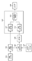
図1は、実施形態における画像処理装置のブロック構成図である。 FIG. 1 is a block diagram of an image processing apparatus according to the embodiment.
図示において、100は本実施形態の主要部分であるブロック歪み評価部であって、内部には空間微分器101、102、及び評価情報演算部103を含むものである。104は符号化対象の原画像を入力する画像入力部であって、イメージスキャナ、或いはデジタルカメラ等から無圧縮の画像データを入力するものである。105は入力した原画画像を記憶する画像記憶部105である。106は画像記憶部105に記憶された原画像データを圧縮符号化する圧縮符号化部、107は圧縮符号化部106で圧縮符号化する際の符号化パラメータを入力する符号化パラメータ入力部である。108は圧縮符号化したデータを復号し、復号画像を生成する復号部である。109はブロック歪み評価部100からの情報を出力する出力部である。
In the figure,
<第1の実施形態>
上記構成において、ブロック歪み評価部100におけるブロック歪の定量評価指標の算出方法を以下に説明する。
<First Embodiment>
In the above configuration, a block distortion quantitative evaluation index calculation method in the block
なお、実施形態では、ブロック歪の定量評価指標をBND(Blocking Noise Degree)と表し、当該画素の画面内の主走査(水平)画素位置i、副走査(垂直)画素位置j(以下画素位置(i,j)と表す)における水平方向のブロック歪の定量評価指標をBND_h(i,j)、垂直方向のブロック歪の定量評価指標をBND_v(i,j)と表す。また原画像は輝度成分及び色差成分を有しているが、ブロック歪の定量評価は輝度成分値のみを用いて行われるものとする。 In the embodiment, a quantitative evaluation index of block distortion is expressed as BND (Blocking Noise Degree), and the main scanning (horizontal) pixel position i and sub-scanning (vertical) pixel position j (hereinafter referred to as pixel position (hereinafter referred to as pixel position)) in the screen of the pixel. Quantitative evaluation index of block distortion in the horizontal direction is expressed as BND_h (i, j), and quantitative evaluation index of block distortion in the vertical direction is expressed as BND_v (i, j). Further, although the original image has a luminance component and a color difference component, the quantitative evaluation of block distortion is performed using only the luminance component value.
先ず、原画像をX(画像記憶部105に記憶された画像)、復号部108で復号して得られた画像(復号画像)をYと定義する。そして、原画像X中の注目画素の画素値(輝度成分値)をX(i,j)と表現した場合、図12に示すような分布を有することになる。復号画像Yについても同様である。
First, an original image is defined as X (an image stored in the image storage unit 105), and an image (decoded image) obtained by decoding by the
そして、原画像Xの水平方向及び垂直方向の微分値X’_h(i,j)、X’_v(i,j)、並びに、復号画像Yの水平方向、垂直方向の微分値Y’_h(i,j)、Y’_v(i,j)を次のようにして求める。
X'_h(i,j) = X(i,j) - X(i+1,j)
X'_v(i,j) = X(i,j) - X(i,j+1)
Y'_h(i,j) = Y(i,j) - Y(i+1,j)
Y'_v(i,j) = Y(i,j) - Y(i,j+1) (式1)
Then, the horizontal and vertical differential values X′_h (i, j) and X′_v (i, j) of the original image X, and the horizontal and vertical differential values Y′_h ( i, j) and Y′_v (i, j) are obtained as follows.
X'_h (i, j) = X (i, j)-X (i + 1, j)
X'_v (i, j) = X (i, j)-X (i, j + 1)
Y'_h (i, j) = Y (i, j)-Y (i + 1, j)
Y'_v (i, j) = Y (i, j)-Y (i, j + 1) (Formula 1)
そして、原画像Xと復号画像Yの各方向の定量評価指標値BND_h(i,j)、BND_v(i,j)を次の様に求める。
BND_h(i,j) = |X'_h(i,j) - Y'_h(i,j)|
BND_v(i,j) = |X'_v(i,j) - Y'_v(i,j)| (式2)
Then, quantitative evaluation index values BND_h (i, j) and BND_v (i, j) in the respective directions of the original image X and the decoded image Y are obtained as follows.
BND_h (i, j) = | X'_h (i, j)-Y'_h (i, j) |
BND_v (i, j) = | X'_v (i, j)-Y'_v (i, j) | (Formula 2)
上記処理を行う、本第1の実施形態におけるブロック歪み評価部100では、上記の定量評価指標BND_h(i,j)及びBND_v(i,j)を求めるわけであるから、以下により詳しく説明する。
The block
空間微分器101は原画像Xの空間微分値を算出するものであり、空間微分器102は復号画像Yの空間微分値を算出するものである。ただし、これら2つの空間微分器101、102は共に同じ画素位置の空間微分値を算出するため同期している。評価情報演算部103は、これら2つの空間微分器101、102の微分値を入力し、ブロック歪の定量評価指標BND_h(i,j)及びBND_v(i,j)を求める。
The
図1に示したブロック歪み評価部100の構成を、より具体的に示すのが図2である。ただし、図2は、水平方向の定量評価指標BND_h(i,j)を求める構成を示している。垂直方向の定量評価指標BND_h(i,j)を求める構成は、入力する画素の入力方向が垂直方向となるだけで実質的に同じであり、以下の説明から明らかなので省略する。
FIG. 2 shows the configuration of the block
図2において、減算器201は原画像Xの水平1ライン中の隣接する2つの画素値の差分、すなわち、X'_h(i,j)を算出する。隣接する2画素の値を得るには、1画素分だけ遅延するラッチ(フリップフロップ)を用意し、このラッチを介さずに入力した画素データと、ラッチを介した画素データを利用すれば実現できる。
In FIG. 2, the
一方、減算器202も同様に、復号画像Yの水平1ライン中の隣接する2つの画素値の差分、すなわち、Y'_h(i,j)を算出する。減算器203は、減算器201、202からの出力値を減じることで、原画像X及び復号画像Yにおける水平方向の微分値の誤差を得る。この誤差は、この時点で正負の符号を有するものであるので、絶対値化器204で絶対値に変換することで、水平方向の評価指標値BND_h(i,j)を得る。
On the other hand, the subtractor 202 similarly calculates a difference between two adjacent pixel values in one horizontal line of the decoded image Y, that is, Y′_h (i, j). The
上記の如く、図2の構成は非常に単純な構成により水平方向の評価指標値BND_h(i,j)を得ることに成功していることが理解できよう。同様に、垂直方向の評価指標値BND_v(i,j)については、入力する画素が水平ラインでははく、垂直な列になる点で異なるものの、図2と同様の簡単な構成により得ることができる。また、同様の理由でソフトウェアで実現する場合にあっても、その処理は単純であるため非常に高速に処理できるのは明らかである。 As described above, it can be understood that the configuration of FIG. 2 has succeeded in obtaining the horizontal evaluation index value BND_h (i, j) with a very simple configuration. Similarly, the evaluation index value BND_v (i, j) in the vertical direction can be obtained by a simple configuration similar to that in FIG. 2 although the input pixels are different from each other in that they are not horizontal lines but vertical columns. it can. Also, even if the software is implemented for the same reason, it is clear that the processing is simple and can be performed at a very high speed.
さて、標準的な自然画像(例えばデジタルカメラやイメージスキャナで写真を読取った無圧縮の画像)を用いて実際に符号化処理を行い、符号化により生じた水平方向の空間微分値の誤差について測定したところ、図3のようになった。 Now, encoding is actually performed using a standard natural image (for example, an uncompressed image obtained by reading a photograph with a digital camera or an image scanner), and an error of a spatial differential value in the horizontal direction caused by the encoding is measured. As a result, it became like FIG.
図3はある静止画像について3種類の量子化スケール値を用いて符号化した場合の水平方向の空間微分値誤差と画素位置の関係を示している(16×16のマクロブロック分のみ抽出)。図3においてQは量子化スケール値を表している。また、画素位置の中心(画素位置=8)がブロック境界をまたいで空間微分を行った位置を表している。図3から分かるように量子化スケール値を大きくした場合(Q=24)、つまり粗く量子化を行い量子化誤差が大きく生じている場合、ブロック境界における空間微分値誤差がブロック内の値よりも突出してきている様子がわかる。このような場合においてはブロック境界にて顕著な歪、すなわちブロック歪が生じていることを示している。 FIG. 3 shows the relationship between the horizontal spatial differential error and the pixel position when a certain still image is encoded using three types of quantization scale values (only 16 × 16 macroblocks are extracted). In FIG. 3, Q represents a quantization scale value. Further, the center of the pixel position (pixel position = 8) represents the position where spatial differentiation is performed across the block boundary. As can be seen from FIG. 3, when the quantization scale value is increased (Q = 24), that is, when coarse quantization is performed and the quantization error is large, the spatial differential value error at the block boundary is larger than the value in the block. You can see how it protrudes. In such a case, it is shown that significant distortion, that is, block distortion occurs at the block boundary.
ところで、量子化スケール値とブロック歪の発生の関係については画像に依存する(ブロック歪が発生しやすい画像と発生しにくい画像がある)ので一概に決定することができない。しかし、量子化スケール値を大きくするに従ってブロック境界における空間微分値誤差が突出してくるというのは他の画像について符号化処理を行った場合にも見られた現象であった。 By the way, the relationship between the quantization scale value and the occurrence of block distortion depends on the image (there is an image in which block distortion is likely to occur and an image in which block distortion is unlikely to occur), so it cannot be determined unconditionally. However, the fact that the spatial differential value error at the block boundary becomes prominent as the quantization scale value is increased is a phenomenon also seen when encoding processing is performed on other images.
上記のようなブロック境界に発生する歪みは、量子化スケール値に依存するものの、その一方で原画像によっても依存し、且つ、1つの原画像に着目したとしてもある部分では歪みが少なく、ある部分では歪みが大きいということもある。従って、ユーザは、原画像のデータサイズに対する符号化データサイズ(或いは圧縮率)と、符号化画像より得られた復号画像の評価指標値との兼ねないで、ユーザが望む符号化データを生成するため、上記の評価指標値を何らかの手段でユーザに提示することが望ましい。図13は実施形態における機能実現手段をパーソナルコンピュータ等の汎用情報処理装置に実装した場合におけるユーザインタフェースを示している。 The distortion generated at the block boundary as described above depends on the quantization scale value, but on the other hand, it also depends on the original image, and there is little distortion in a part even if attention is paid to one original image. In some cases, distortion may be large. Therefore, the user generates encoded data desired by the user without using both the encoded data size (or compression rate) with respect to the data size of the original image and the evaluation index value of the decoded image obtained from the encoded image. Therefore, it is desirable to present the evaluation index value to the user by some means. FIG. 13 shows a user interface when the function realizing means in the embodiment is mounted on a general-purpose information processing apparatus such as a personal computer.
図13において、1300はユーザインタフェースとなるウインドウを示している。1301は原画像のファイルを所在を入力するファイル名フィールドであり、無圧縮の画像を選択するものである。なお、ボタン1302をクリックすることで、ファイル選択のためのブラウザを表示し選択することも可能となっている。なお、ファイルの指定ではなく、イメージスキャナやデジタルカメラ等から無圧縮の画像を直接入力するようにしても良い。
In FIG. 13,
1303は、指定された原画像を表示する表示領域であり、1304は原画像を圧縮符号化した後の復号画像を表示する領域である。なお、圧縮符号化後のファイルは原画像と同じパスに拡張子「jpg」として保存されるものとする。
1305は量子化テーブルを選択するためのものであり、ここではコンボボックス形式にした(量子化テーブルを選択するためであればいかなる形態でもよいのは勿論である)。すなわち、図示の右端をクリックすることで、予め登録された複数の量子化テーブルが表示され、ユーザはその中の1つを選択することで圧縮符号化時の量子化テーブルを決定することになる(デフォルトでは「量子化テーブル1」が選択)。1306は圧縮符号化の開始を指示するボタンであり、このボタン1306をクリックすることで、指定された原画像を、指定された量子化テーブルを利用してJPEG圧縮符号化を行い、その結果えられた圧縮符号化データを復号し、それを領域1304に表示することになる。
1307は歪み評価結果表示領域であって、実施形態では、先に説明したように水平方向、及び、垂直方向のブロック歪み評価指標値を演算するので、図示の如く2つの表示領域1308、1309を設けた。
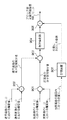
以下、図13におけるウインドウ1300で示される評価アプリケーションの動作処理手順を図14のフローチャートに従って説明する。
Hereinafter, the operation processing procedure of the evaluation application indicated by the
先ず、ステップS1で原画像のファイル名を入力する(もしくは原画像を入力する)。この入力が行われると、図13の領域1303にその画像が表示される。なお、領域1303に対して原画像のサイズが大きいのが一般的であるから、間引き処理、複数画素の平均して1画素を生成する等を行い、縮小画像を生成して表示する。また、原画像のデータサイズを図示のように表示する。
First, in step S1, the file name of the original image is input (or the original image is input). When this input is performed, the image is displayed in an
次いで、ステップS2に進み、符号化パラメータ(実施形態では量子化テーブル)を決定する。これは図13におけるコンボボックス1305を操作することで行う。この後、ステップS3にて符号化開始ボタン1306がクリックされるのを待つことになる。
Next, the process proceeds to step S2, and an encoding parameter (quantization table in the embodiment) is determined. This is done by operating the
符号化の開始の指示があると、処理はステップS4に進み、指定(入力)された原画像を、そのときに指定された符号化パラメータ(量子化テーブル)に従って圧縮符号化処理を行う。圧縮符号化された画像データは、原画像と同じ位置、或いは予め設定された場所にJPEGファイルとして保存する。 If there is an instruction to start encoding, the process proceeds to step S4, and the specified (input) original image is subjected to compression encoding processing according to the encoding parameter (quantization table) specified at that time. The compression-coded image data is saved as a JPEG file at the same position as the original image or at a preset location.
圧縮符号化が完了すると、ステップS5に進み、作成された圧縮符号化データを復号し、その復号画像を領域1304に表示する。このときの表示処理そのものは原画像と同様にして表示する。そして、その際には、圧縮符号化したファイルのデータサイズも併せて表示する(圧縮率でも良いし、両方を表示しても良い)。
When the compression encoding is completed, the process proceeds to step S5, where the generated compression encoded data is decoded, and the decoded image is displayed in the
次いで、ステップS6に進み、先に説明した処理を行うことで水平、垂直方向の評価指標値を演算処理を行い、ステップS7にて演算した結果を視覚的に分かりやすいように画像化して領域1308、1309それぞれに表示する。このあと、ステップS8で処理を終えるとの指示があれば本処理を終えるが、圧縮符号化サイズ(或いは圧縮率)と歪みとの関係に不満がある場合には、ステップS2からの処理を繰り返すことになる。 Next, the process proceeds to step S6, where the above-described processing is performed to calculate the evaluation index values in the horizontal and vertical directions, and the result calculated in step S7 is imaged so that it can be easily understood visually. , 1309 respectively. Thereafter, if there is an instruction to end the process in step S8, the process ends. If the relationship between the compression encoding size (or compression rate) and the distortion is unsatisfactory, the process from step S2 is repeated. It will be.
上記処理中、ステップS7での処理について具体例を以下に説明する。実施形態では、JPEG符号化を例にしている。ここでDCT処理が8×8画素ブロックを単位に行っているとする。 A specific example of the process in step S7 during the above process will be described below. In the embodiment, JPEG encoding is taken as an example. Here, it is assumed that the DCT process is performed in units of 8 × 8 pixel blocks.
個々のブロックのサイズが既知であるから、各ブロック間の境界位置も既知である。また、各ブロックには水平方向に隣接する2つのブロックが存在し、且つ、垂直方向にも2つのブロックが隣接することになる(画像の端のブロックは水平方向、垂直方向の少なくとも一方に隣接するブロックが存在しない)。 Since the size of each block is known, the boundary position between each block is also known. Each block has two blocks adjacent in the horizontal direction, and two blocks are also adjacent in the vertical direction (the block at the end of the image is adjacent to at least one of the horizontal direction and the vertical direction). Does not exist).
実施形態では、ブロック境界における歪み評価指標値を問題にしている。そこで、8×8画素ブロックの境界に位置する画素30画素以外の、内部の6×6画素領域の水平方向の評価指標値の平均値(以下、ブロック内水平評価指標値という)と、内部の6×6画素領域の垂直方向の評価指標値の平均値(以下、ブロック内垂直評価指標値という)を求める。そして、水平方向の境界に位置する左右の16個の評価値の平均値(以下、ブロック境界水平評価指標値という)、垂直方向の境界に位置する上下の16個の評価値の平均値(以下、ブロック境界垂直評価指標値という)を求める。 In the embodiment, the problem is the distortion evaluation index value at the block boundary. Therefore, the average value of the horizontal evaluation index values (hereinafter referred to as the intra-block horizontal evaluation index value) of the internal 6 × 6 pixel area other than 30 pixels located at the boundary of the 8 × 8 pixel block, and the internal An average value of evaluation index values in the vertical direction of the 6 × 6 pixel region (hereinafter referred to as an intra-block vertical evaluation index value) is obtained. Then, an average value of 16 left and right evaluation values positioned at the horizontal boundary (hereinafter referred to as a block boundary horizontal evaluation index value), and an average value of 16 upper and lower evaluation values positioned at the vertical boundary (hereinafter referred to as the block boundary horizontal evaluation index value). , Called block boundary vertical evaluation index value).
そして、ブロック境界水平評価指標値からブロック内水平評価指標値を減算した結果を、該当するブロックの水平方向のブロック歪み評価量として決定する。同様に、ブロック境界垂直評価指標値からブロック内垂直評価指標値を減算した結果をそのブロックの垂直方向のブロック歪み評価量として決定する。 Then, the result of subtracting the intra-block horizontal evaluation index value from the block boundary horizontal evaluation index value is determined as the block distortion evaluation amount in the horizontal direction of the corresponding block. Similarly, the result of subtracting the intra-block vertical evaluation index value from the block boundary vertical evaluation index value is determined as the block distortion evaluation amount in the vertical direction of the block.
このようにして得られた水平及び垂直方向のブロック非積み評価量を輝度情報として、図13における領域1308、1309それぞれに表示する。従って、ユーザは輝度が高いほど、そのブロック歪みが高いことを知ることができるので、他の符号化パラメータを選択する指標を得ることができるようになる。なお、ここでは輝度のグレイスケールで歪みを表現したが、色別で表現しても良い。
The horizontal and vertical block non-stack evaluation values obtained in this way are displayed as luminance information in the
以上説明したように本実施形態によれば、画像を圧縮符号化した際に、その圧縮した結果を復号した復号画像が、原画像に対する客観的なブロック歪み量をユーザに知らしめることが可能となる。また、ユーザは、圧縮後のデータサイズや圧縮率と、ブロック歪みとの関係を着目しながらデータサイズと画質を決めることが可能になる。 As described above, according to the present embodiment, when an image is compressed and encoded, a decoded image obtained by decoding the compressed result can inform the user of an objective block distortion amount with respect to the original image. Become. Further, the user can determine the data size and the image quality while paying attention to the relationship between the compressed data size and compression rate and the block distortion.
なお、上記はパーソナルコンピュータ等の汎用情報処理装置にアプリケーションとして実装する例を示したが、例えばデジタルカメラ等に実装しても良い。デジタルカメラにおいては表示画面は限られたサイズであるので、図13のような表示は難しいので、それぞれの画像表示領域を適宜切り換える等を行うことになるであろう。 In the above example, the application is installed in a general-purpose information processing apparatus such as a personal computer. However, the application may be installed in a digital camera, for example. Since the display screen of a digital camera is limited in size, it is difficult to display as shown in FIG. 13, so that the respective image display areas will be switched as appropriate.
<第2の実施形態>
次に第2の実施形態を説明する。本第2の実施形態においては、水平方向及び数直方向のブロック歪の定量評価指標BND_h(i,j)、BND_v(i,j)を以下のようにして求める。
BND_h(i,j) = Dh(i,j)/(Dh_av)
BND_v(i,j) = Dv(i,j)/(Dv_av)
Dh(i,j)= |X'_h(i,j) - Y’_h(i,j)|
Dv(i,j)= |X'_v(i,j) - Y’_v(i,j)|
<Second Embodiment>
Next, a second embodiment will be described. In the second embodiment, the quantitative evaluation indexes BND_h (i, j) and BND_v (i, j) of block distortion in the horizontal direction and the straight direction are obtained as follows.
BND_h (i, j) = Dh (i, j) / (Dh_av)
BND_v (i, j) = Dv (i, j) / (Dv_av)
Dh (i, j) = | X'_h (i, j)-Y'_h (i, j) |
Dv (i, j) = | X'_v (i, j)-Y'_v (i, j) |
このBND_h(i,j)、BND_v(i,j)が大きい程ブロック歪が大きく生じていると言える。なお、Dh(i,j)、Dv(i,j)は、それぞれ水平、垂直方向の符号化処理による空間微分値誤差を表し、Dh_avはDh(i.j)に関して、同じブロック内の垂直位置が同じである画素についての空間微分値誤差の平均を計算したものである。Dv_avはDv(i,j)に関して同じブロック内の水平位置が同じである画素についての空間微分値誤差の平均を計算したものである。 It can be said that the larger the BND_h (i, j) and BND_v (i, j), the greater the block distortion. Dh (i, j) and Dv (i, j) represent spatial differential error due to horizontal and vertical encoding processes, respectively, and Dh_av is a vertical position within the same block with respect to Dh (i.j). Is the average of spatial differential error for pixels with the same. Dv_av is an average of spatial differential error for pixels having the same horizontal position in the same block with respect to Dv (i, j).
第2の実施形態において空間微分値の計算は垂直方向、垂直方向を別々に、中心差分公式による数値微分を用いて行った。中心差分公式による数値微分を用いた場合、原画像の輝度値X(i,j)の水平方向の空間微分値X'_(i,j)、垂直方向の空間微分値X'_v(i,j)は以下のように得ることができる。復号画像についても同様である。
X'_h(i,j) = (X(i-1,j) - X(i+1,j))/2
X'_v(i,j) = (X(i-1,j) - X(i,j+1))/2
In the second embodiment, the calculation of the spatial differential value was performed using numerical differentiation based on the central difference formula separately in the vertical direction and the vertical direction. When the numerical differentiation based on the center difference formula is used, the horizontal spatial differential value X ′ _ (i, j) of the original image luminance value X (i, j), the vertical spatial differential value X′_v (i, j, j) can be obtained as follows. The same applies to the decoded image.
X'_h (i, j) = (X (i-1, j)-X (i + 1, j)) / 2
X'_v (i, j) = (X (i-1, j)-X (i, j + 1)) / 2
図4は本第2の実施形態におけるブロック歪の定量評価指標(水平方向のみ、垂直方向も同様の構成となる)の算出の構成を示している。 FIG. 4 shows a configuration for calculating a block distortion quantitative evaluation index (only in the horizontal direction and the same configuration in the vertical direction) in the second embodiment.
図示されるように減算器401、減算器402、除算器403、除算器404、減算器405、絶対値化器406、除算器407を含む。図4において減算器401、除算器403は中心差分方式を用いた数値微分演算を行うためにX(i−1,j)とX(i+1,j)の差分、および“2”による除算を行う。同様に減算器402、除算器404はY(i−1,j)とY(i+1,j)の差分、及び“2”による除算を行う。減算器405は空間微分値の符号化処理による誤差を計算するために、除算器403と除算器404の出力の差分を計算している。絶対値化器406は誤差を正の値に統一するための絶対値化を行い、当該ブロックの水平方向の空間微分値誤差Dh(i,j)を出力する。除算器407はブロック内での平均空間微分値誤差と当該画素における空間微分値である絶対値化器406との比を計算し、結果であるBND_h(i,j)を出力している。
As shown in the figure, a
本第2の実施形態において、ブロック境界におけるBND_h(i,j)が大きくなった場合に、ブロック境界における空間微分値誤差がブロック内の平均値よりも突出していることを表しており、ブロック歪が発生していると考えられる。実際に自然画を用いて符号化を行ったところ、おおよそBND_h(i,j)が“1.2”より大きくなった場合に視覚的にブロック歪が目立つようになる、ということが確認できた。前述したように量子化スケール値を大きくするに従ってブロック境界における空間微分値誤差が周辺画素における値に比べて突出してくるというのはどのような画像においてもほぼ見受けられる現象である。よってこのように、空間微分値誤差に関してブロック境界における値とブロック内における値とを相対的に比較することにより、対象となる画像に依存せず、より正確にブロック歪の発生を検出し、定量評価することが可能となる。なお、第2の実施形態においてはブロック内の空間微分値誤差を表す値として平均値を用いたが、より計算が簡単になるようにブロック内の中央値等を用いることもできる。 In the second embodiment, when BND_h (i, j) at the block boundary becomes large, the spatial differential value error at the block boundary is more prominent than the average value in the block, and block distortion Is considered to have occurred. When encoding was actually performed using natural images, it was confirmed that block distortion becomes visually noticeable when BND_h (i, j) is larger than “1.2”. . As described above, as the quantization scale value is increased, the spatial differential value error at the block boundary protrudes from the values at the peripheral pixels, which is a phenomenon that can be seen in any image. Therefore, by comparing the value at the block boundary with the value in the block relative to the spatial differential value error in this way, the occurrence of block distortion can be detected more accurately and quantified without depending on the target image. It becomes possible to evaluate. In the second embodiment, the average value is used as a value representing the spatial differential value error in the block. However, a median value in the block or the like can be used so as to make the calculation easier.
また、実際の評価結果の表示方法は、第1の実施形態における図13、図14に沿って行うものとし、その説明については省略する。かかる点は、以下に説明する各実施形態でも同様である。 Moreover, the display method of an actual evaluation result shall be performed along FIG. 13, FIG. 14 in 1st Embodiment, and it abbreviate | omits about the description. This is the same in each embodiment described below.
<第3の実施形態>
第3の実施形態を説明する。本第3の実施形態においては、以下のように人間の視覚特性(空間微分値に関する)を考慮してブロック歪の評価指標の計算を行っている点を特徴とする。第3の実施形態における水平方向及び数直方向のブロック歪の定量評価指標BND_h(i,j)、BND_v(i,j)は以下のようにして求める。
BND_h(i,j) = Dh(i,j)/(α×X'_h(i,j) + β)
BND_v(i,j) = Dv(i,j)/(α×X'_v(i,j) + β)
<Third Embodiment>
A third embodiment will be described. The third embodiment is characterized in that a block distortion evaluation index is calculated in consideration of human visual characteristics (related to spatial differential values) as follows. The quantitative evaluation indices BND_h (i, j) and BND_v (i, j) of the block distortion in the horizontal direction and the straight direction in the third embodiment are obtained as follows.
BND_h (i, j) = Dh (i, j) / (α × X'_h (i, j) + β)
BND_v (i, j) = Dv (i, j) / (α × X'_v (i, j) + β)
このBND_h(i,j)、BND_v(i,j)が大きい程ブロック歪が大きく生じていると言える。ここで、空間微分値誤差Dh(i,j)、Dv(i,j)については第2の実施形態と、空間微分演算については第1の実施形態と同様の計算を行っている。また原画像の空間微分値に係る係数α及び固定値βは人間の視覚特性に関する空間微分値のブロック歪の定量評価指標への影響を示している。αが大きくなり、βが小さくなる場合に空間微分値のブロック歪の定量評価指標への影響が大きくなる。 It can be said that the larger the BND_h (i, j) and BND_v (i, j), the greater the block distortion. Here, the spatial differential value errors Dh (i, j) and Dv (i, j) are calculated in the same manner as in the second embodiment, and the spatial differential calculation is performed in the same manner as in the first embodiment. The coefficient α and the fixed value β related to the spatial differential value of the original image indicate the influence of the spatial differential value related to human visual characteristics on the quantitative evaluation index of block distortion. When α increases and β decreases, the influence of the spatial differential value on the quantitative evaluation index of block distortion increases.
図5は本第3の実施形態におけるブロック歪の定量評価指標(水平方向のみ、垂直方向についても同様の構成となる)の算出するための構成を示している。 FIG. 5 shows a configuration for calculating a block distortion quantitative evaluation index (only in the horizontal direction and the same configuration in the vertical direction) in the third embodiment.
図示されるように減算器501、減算器502、減算器503、絶対値化器504、乗算器505、加算器506、除算器507を含む。図5において減算器501、減算器502は前進差分方式による数値微分法を用いて原画像Xと復号画像Yについて水平方向の空間微分演算を行う。減算器503は空間微分値の符号化処理による誤差を計算するために、減算器501と減算器502の出力の差分を計算している。絶対値化器504は誤差を正の値に統一するための絶対値化を行い、当該ブロックの水平方向の空間微分値誤差Dh(i,j)を出力する。乗算器505において視覚特性を考慮するために原画像の空間微分値X'_h(i,j)と係数αとの乗算を行っている。加算器506においてはゼロによる割り算を防ぐために、乗算器505の出力と固定値βとの加算を行っている。除算器507は人間の視覚特性を考慮するために、絶対値化器504の出力と加算器506の出力との比を計算し、結果であるブロック歪の定量評価指標BND_h(i,j)を出力している。
As shown in the figure, a
本第3の実施形態においては、ブロック境界に大きな歪が生じ、かつブロック歪が目立ちやすい原画像の平坦部にブロック歪が生じている場合にBND_h(9i,j)が大きくなるので、視覚的な劣化として目立つブロック歪をより正確に検出することが可能となる。 In the third embodiment, BND_h (9i, j) increases when block distortion occurs in the flat portion of the original image where block distortion is prominent and block distortion is conspicuous. It is possible to more accurately detect block distortion that is noticeable as a serious deterioration.
また図5に示されているように、視覚特性として考慮に入れる原画像の空間微分値は減算器501の出力を用いることができるのでハードウェアでこのようなブロック歪定量評価器を実現する場合に少ない回路構成で実現できることがわかる。
Further, as shown in FIG. 5, since the output of the
<第4の実施形態>
本第4の実施形態においては、以下のように、人間の視覚特性(原画像の輝度値に関する)を考慮してブロック歪の定量評価指標の計算を行う。
<Fourth Embodiment>
In the fourth embodiment, the quantitative evaluation index of block distortion is calculated in consideration of human visual characteristics (related to the luminance value of the original image) as follows.
先ず、本第4の実施形態において、水平方向及び数直方向のブロック歪の定量評価指標BND_h(i,j)、BND_v(i,j)を以下のようにして求める。
BND_h(i,j) = W_lum(i,j)×Dh(i,j)
BND_v(i,j) = W_lum(i,j)×Dv(i,j)
First, in the present fourth embodiment, the quantitative evaluation indexes BND_h (i, j) and BND_v (i, j) of the block distortion in the horizontal direction and the straight direction are obtained as follows.
BND_h (i, j) = W_lum (i, j) × Dh (i, j)
BND_v (i, j) = W_lum (i, j) × Dv (i, j)
このBND_h(i,j)、BND_v(i,j)が大きい程ブロック歪が大きく生じていると言える。ここで、空間微分値誤差Dh(i,j)、Dv(i,j)については第2の実施形態と、空間微分演算については第1の実施形態と同様の計算を行っている。またW_lum(i,j)は原画像の輝度値X(i,j)に対応したブロック歪の定量評価指標に係る係数である。原画像の輝度値と係数の関係を図6に示す。図6に示されている関係は輝度値がある範囲内にある場合にはブロック歪が視覚的に目立ち、範囲外にある場合には目立ちにくいという人間の視覚特性を考慮して決定された。 It can be said that the larger the BND_h (i, j) and BND_v (i, j), the greater the block distortion. Here, the spatial differential value errors Dh (i, j) and Dv (i, j) are calculated in the same manner as in the second embodiment, and the spatial differential calculation is performed in the same manner as in the first embodiment. W_lum (i, j) is a coefficient relating to a quantitative evaluation index of block distortion corresponding to the luminance value X (i, j) of the original image. FIG. 6 shows the relationship between the luminance value of the original image and the coefficient. The relationship shown in FIG. 6 is determined in consideration of human visual characteristics that block distortion is visually noticeable when the luminance value is within a certain range, and is not noticeable when the luminance value is outside the range.
図7は本第4の実施形態におけるブロック歪の定量評価指標(水平方向のみ、垂直方向についても同様の構成となる)の算出に係る構成を示している。図示されるように減算器701、減算器702、減算器703、絶対値化器704、記憶装置705、乗算器706を含む。
FIG. 7 shows a configuration related to calculation of a block distortion quantitative evaluation index (only the horizontal direction and the same configuration in the vertical direction) in the fourth embodiment. As shown in the figure, a
図7において減算器701、減算器702は前進差分方式による数値微分法を用いて原画像と復号画像について水平方向の空間微分演算を行う(垂直方向も同様であるので省略)。減算器703は空間微分値の符号化処理による誤差を計算するために、減算器701と減算器702の出力の差分を計算している。絶対値化器704は誤差を正の値に統一するための絶対値化を行い、当該ブロックの水平方向の空間微分値誤差Dh(i,j)を出力する。記憶装置705は、原画像の輝度値X(i,j)が入力されると図6に示されている対応した係数の値W_lum(i,j)を出力する。乗算器706は絶対値化器704から出力されるDh(i,j)に記憶装置705から出力される係数W_lum(i,j)を乗じ、結果であるBND_h(i,j)を出力する。
In FIG. 7, a
本第4の実施形態においては、ブロック境界に大きな歪が生じており、かつ輝度値がブロック歪の目立つ範囲内に存在する場合にBND_h(i,j)が大きくなるので、視覚的な劣化として目立つブロック歪をより正確に検出することが可能となる。 In the fourth embodiment, BND_h (i, j) becomes large when a large distortion occurs at the block boundary and the luminance value is within a conspicuous range of the block distortion. It becomes possible to detect conspicuous block distortion more accurately.
<第5の実施形態>
本第5の実施形態においては、人間の視覚特性(注目画素の画面内における位置に関する)を考慮してブロック歪の評価指標の計算を行うものである。本第5の実施形態において、水平方向及び数直方向のブロック歪の定量評価指標BND_h(i,j)、BND_v(i,j)は以下のように表す。
BND_h(i,j) = P_x(i,j)×Dh(i,j)
BND_v(i,j) = P_x(i,j)×Dv(i,j)
<Fifth Embodiment>
In the fifth embodiment, a block distortion evaluation index is calculated in consideration of human visual characteristics (related to the position of the target pixel in the screen). In the fifth embodiment, the quantitative evaluation indexes BND_h (i, j) and BND_v (i, j) of the block distortion in the horizontal direction and the straight direction are expressed as follows.
BND_h (i, j) = P_x (i, j) × Dh (i, j)
BND_v (i, j) = P_x (i, j) × Dv (i, j)
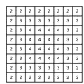
このBND_h(i,j)、BND_v(i,j)が大きい程ブロック歪が大きく生じていると言える。ここで、空間微分値誤差Dh(i,j)、Dv(i,j)については第2の実施形態と、空間微分演算については第1の実施形態と同様の計算を行っている。またP_x(i,j)は当該画素の画素位置(i,j)に対応したブロック歪の定量評価指標に係る係数である。当該画素の画面内における位置と係数の関係を図8に示す。図8の升目中の数字がマクロブロックの位置に対応したブロック歪の定量評価指標に係る係数P_x(i,j)を示しており、マクロブロック内においては全て同じ係数を用いる。図8は当該画素が画面内の中心に近い程ブロック歪が視覚的に目立ち、画面内の端に近い程目立ちにくいという人間の視覚特性を考慮して決定された。なお、図8はマス目の数が9×9であるが、勿論、これは原画像のサイズに応じたものとなる。要するに、画像の中心位置ほど、P_xの値を大きくするものであることは望ましいことを示している。 It can be said that the larger the BND_h (i, j) and BND_v (i, j), the greater the block distortion. Here, the spatial differential value errors Dh (i, j) and Dv (i, j) are calculated in the same manner as in the second embodiment, and the spatial differential calculation is performed in the same manner as in the first embodiment. P_x (i, j) is a coefficient related to the block distortion quantitative evaluation index corresponding to the pixel position (i, j) of the pixel. FIG. 8 shows the relationship between the position of the pixel in the screen and the coefficient. The numbers in the grid in FIG. 8 indicate the coefficient P_x (i, j) related to the quantitative evaluation index of block distortion corresponding to the position of the macroblock, and the same coefficient is used in all the macroblocks. FIG. 8 is determined in consideration of human visual characteristics that the block distortion is more visually noticeable as the pixel is closer to the center in the screen, and is less noticeable as the pixel is closer to the edge in the screen. In FIG. 8, the number of squares is 9 × 9. Of course, this corresponds to the size of the original image. In short, it is indicated that it is desirable to increase the value of P_x toward the center of the image.
図9は本第5の実施形態におけるブロック歪の定量評価指標(水平方向のみ、垂直方向についても同様の構成となる)の算出する構成を示している。図示されるように減算器901、減算器902、減算器903、絶対値化器904、記憶装置905、乗算器906を含む。
FIG. 9 shows a configuration for calculating a block distortion quantitative evaluation index (only the horizontal direction and the same configuration in the vertical direction) according to the fifth embodiment. As shown in the figure, a
図9において減算器901、減算器902は前進差分方式による数値微分法を用いて原画像と復号画像について水平方向の空間微分演算を行う。減算器903は空間微分値の符号化処理による誤差を計算するために、減算器901と減算器902の出力の差分を計算している。絶対値化器904は誤差を正の値に統一するための絶対値化を行い、当該ブロックの水平方向の空間微分値誤差Dh(i,j)を出力する。記憶装置905は、当該画素の画面内における位置(i,j)をアドレスとして入力されると図8に示される対応した係数の値P_x(i,j)を出力する。乗算器906は絶対値化器904から出力されるDh(i,j)に記憶装置905から出力される係数P_x(i,j)を乗じ、結果であるBND_h(i,j)を出力する。
In FIG. 9, a
本第5の実施形態においては、ブロック境界において大きな歪が生じており、画面の中心付近に存在する場合にブロック歪を示すBND_h(i,j)が大きくなるので、視覚的な劣化として目立つブロック歪を、より正確に検出することが可能となる。 In the fifth embodiment, a large distortion occurs at the block boundary, and BND_h (i, j) indicating the block distortion increases when the block boundary exists near the center of the screen. Distortion can be detected more accurately.
<第6の実施形態>
本第6の実施形態は、動画像符号化装置において前記ブロック歪定量評価器を実装したものである。
<Sixth Embodiment>
In the sixth embodiment, the block distortion quantitative evaluator is implemented in a moving image coding apparatus.
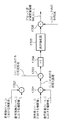
図10は本第6の実施形態における動画像符号化装置のブロック構成図である。図示に示すように、本装置は、減算器1001、DCT演算器1002、量子化器1003、スキャン処理器1004、エントロピー符号化器1005、逆量子化器1006、逆DCT演算器1007、加算器1008、記憶装置1009、動き検出器及び動き補償器1010、記憶装置1011、ブロック歪定量評価器1012を含む。
FIG. 10 is a block diagram of a moving picture coding apparatus according to the sixth embodiment. As shown in the figure, this apparatus includes a subtracter 1001, a
図10において、減算器1001はフレーム内の情報のみで符号化を行うフレーム内符号化においては減算処理が実行されずにDCT演算器1002へ、入力の原画像データを出力する。一方、時間的に異なるフレームからの予測を行うフレーム間予測符号化においては、入力の原画像データから動き検出器及び補償器より出力される動き検出画像データを減算して、減算結果の予測誤差をDCT演算器1002へ出力する。
In FIG. 10, the subtracter 1001 outputs the input original image data to the
DCT演算器1002は、ブロック分割された入力データに対し、該ブロック単位にDCT変換を施し、DCT係数を量子化器1003へ出力する。量子化器1003は、ブロック内の位置に対応する量子化テーブル値と当該ブロックの量子化スケール値を用いてDCT係数を量子化し、全ての量子化DCT係数をスキャン処理器1004へ出力し、同時に逆量子化器1006に出力する。スキャン処理器1004は符号化モードに応じてジグザグスキャン、垂直スキャン及び水平スキャン等のスキャン処理を行う。エントロピー符号化器1005はスキャン処理器1004の出力をエントロピー符号化し、符号として出力する。
The
ここで第6の実施形態の動画像符号化装置においては動き検出及び動き補償を行うために、逆量子化器1006、逆DCT演算器1007を用いて局所復号化処理が行われる。
Here, in the moving image encoding apparatus of the sixth embodiment, local decoding processing is performed using an inverse quantizer 1006 and an
逆量子化器1006においては当該ブロックの量子化スケール値を用いて当該ブロックの量子化DCT係数の逆量子化が行われ、逆量子化係数を逆DCT演算器1007へ出力する。逆DCT演算器1007は逆量子化されたDCT係数に対し、該ブロック単位に逆DCT変換を施し、復号した予測誤差を加算器1008へ出力する。加算器1008は動き検出器及び動き補償器1010から出力された予測値と逆DCT演算器からの復号された予測誤差を加算することにより復号化された参照画像(復号フレーム)として記憶装置1009に記憶する。
The inverse quantizer 1006 performs inverse quantization of the quantized DCT coefficient of the block using the quantization scale value of the block, and outputs the inverse quantized coefficient to the
ここで、動画像符号化装置に実装されたブロック歪定量評価器1012は記憶装置1011に記憶された原画像の輝度成分と、加算器1008から得られる復号画像の輝度成分を入力とする。そしてブロック歪定量評価手段を用いてブロック歪を定量評価し、結果であるブロック歪の定量評価指標を出力する。ここでブロック歪定量評価器は前記各実施形態のいずれの方式でも用いることが可能である。図10に示す通り、ブロック歪定量評価器の入力となる復号画像は一般的な動画像符号化方式における局所復号化装置により算出されるものなので、復号画像の計算のために特別な回路の増加を必要としない。よって動画像符号化装置において最小限の回路規模の増加でブロック歪定量評価器を実装することができ、以下に示すような高画質化処理を行うことが可能となる。
Here, the block distortion
なお、評価量を確認する場合には、各フレーム毎の評価量を入力する動画像と同様に、歪みの大きい位置を高い輝度(或いは色を変える等)とする動画像として表示することになる。 When the evaluation amount is confirmed, like a moving image for inputting the evaluation amount for each frame, a position with a large distortion is displayed as a moving image with high luminance (or a color is changed). .
一般的に動画は時間的な相関が強く、同じ符号化を行った場合には現在のピクチャにおけるブロック歪と次のピクチャにおいて生じるブロック歪の間にも強い相関がある。よって現在のピクチャの情報から次のピクチャに対するブロック歪の低減処理(ブロック歪を低減させる部分及び低減処理の強弱)を決定する。 In general, moving images have a strong temporal correlation, and when the same coding is performed, there is also a strong correlation between block distortion in the current picture and block distortion that occurs in the next picture. Therefore, the block distortion reduction process (the part that reduces the block distortion and the strength of the reduction process) for the next picture is determined from the information of the current picture.
図10においてはブロック歪定量評価器1012から出力される定量評価指標を量子化器1003にフィードバックし、ある一部のマクロブロックにのみブロック歪が生じている場合には次のピクチャにおいて同じ位置に相当するマクロブロックの量子化スケール値を小さくし、ブロック歪の生じていないマクロブロックの量子化スケール値を上げるというような処理を行うことで指定されたビットレートを保ちながら画面全体として生じるブロック歪を低減させることが可能となる。なお、予め複数の閾値を設け、マクロブロックのブロック歪みの指標値がどの閾値間にあるかに基づいて歪みレベルを求め、それに応じた量子化スケール値を選択するようにすれば実現できる。
In FIG. 10, the quantitative evaluation index output from the block distortion
動画像符号化装置においてこのような処理を行うことにより、低ビットレートで符号化し、MPEG等の動画像符号化国際標準に準拠した一般的な復号化装置によって復号した場合においても画質劣化を最小限に抑えることが可能となる。 By performing such processing in the moving image coding apparatus, image quality degradation is minimized even when encoded at a low bit rate and decoded by a general decoding apparatus that complies with international moving image coding standards such as MPEG. It becomes possible to limit to the limit.
<第7の実施形態>
第7の実施形態においては、デジタルビデオカメラ等の動画撮影装置に適用した例を説明する。
<Seventh Embodiment>
In the seventh embodiment, an example applied to a moving image capturing apparatus such as a digital video camera will be described.
図11は本第7の実施形態における動画像撮影装置内の画像処理装置、及び動画像符号化装置をブロック図である。図示されるように本装置には、画像処理部1101、画像処理部内のフィルタ処理装置1102、動画像符号化装置1103、記憶装置1104、ブロック歪定量評価器1105を含む。
FIG. 11 is a block diagram of an image processing device and a moving image encoding device in the moving image capturing device according to the seventh embodiment. As illustrated, the apparatus includes an
本第7の実施形態の動画撮影装置においては撮影光学系からの電気信号に対して画像処理部1101内部のフィルタ処理装置1102においてフィルタ処理を行ってから原画像を動画像符号化装置1103に出力する。ここでフィルタ処理の周波数特性を変化させることにより動画像符号化装置1103に入力される原画像の周波数特性を変化させることが可能である。
In the moving image shooting apparatus according to the seventh embodiment, the electric signal from the shooting optical system is filtered by the
図11において動画像処理装置1103は第6の実施形態に示した動画像処理装置と同様の構成になっており、符号を出力すると同時に局所復号化装置から復号画像を出力する。
In FIG. 11, a moving
ブロック歪定量評価器1105は記憶装置1104に記憶した原画像の輝度成分、及び動画像符号化装置1103からの復号された復号画像を入力とする。そして第1乃至第5の実施形態のいずれかのブロック歪定量評価手段を用いて定量評価を行い、結果であるブロック歪の定量評価指標を画像処理部内のフィルタ処理装置1102へ出力する。フィルタ処理装置1102においては入力されたブロック歪定量評価指標(ブロック歪の発生している箇所、度合いの情報)を用いてフィルタ処理装置のフィルタの周波数特性を変化させる。このフィルタ処理はブロック処理の単位等に依存せず、ブロック境界を含んだ広い範囲等任意の範囲でフィルタ処理を変化させることが可能であり、ブロック境界に生じるブロック歪を低減させることが可能である。ブロック歪が大きく生じている部分には、次のピクチャの同じ部分に対してよりカットオフ周波数の低いローパスフィルタとなるようにフィルタ特性を変化させる。カットオフ周波数を下げることにより、動画像符号化装置に入力される原画像においてブロック歪が発生する周波数成分を含む高周波成分が予め低減され、かつエントロピー符号化部において符号化効率が向上する。結果として、復号画像におけるブロック歪を低減させることが可能となる。
The block distortion
このように動画像符号化装置においてブロック歪定量評価器1105を実装することにより正確にブロック歪を定量評価し、必要な場合にのみブロック歪低減処理を実行することができる。よって、低ビットレートで符号化し、MPEG等の動画像符号化国際標準に準拠した一般的な復号化装置によって復号した場合においても画質劣化を最小限に抑えることが可能となる。
In this way, by mounting the block distortion
<他の実施形態>
上記第1乃至第7の実施形態は、その基本構成として図1に示すように、空間微分器101で原画像の空間微分値を演算し、空間微分器102で復号画像の微分値を演算し、比較器103で、その2つの演算結果を受けて評価情報演算部103によって評価量を決定するものであった。
<Other embodiments>
In the first to seventh embodiments, as shown in FIG. 1, the
本発明はかかる点に限定されるものではない。すなわち、図15に示すように、先ず、原画像Xと復号画像Yとの差分を減算器1501により演算し、空間微分器1502にてその差分値の微分値を演算し、比較器1503にて評価量を決定するようにしても良い。
The present invention is not limited to this point. That is, as shown in FIG. 15, first, the difference between the original image X and the decoded image Y is calculated by the
図16は、その具体的な構成例を示している。同図は水平方向の定量評価指標値BND_h(i,j)を得るための構成を示し、ちょうど先に説明した第1の実施形態に対応するものであり、第1の実施形態の変形例とするものである。 FIG. 16 shows a specific configuration example thereof. This figure shows a configuration for obtaining a quantitative evaluation index value BND_h (i, j) in the horizontal direction, which corresponds to the first embodiment described above, and a modification of the first embodiment. To do.
すなわち、減算器1601では原画像及び復号画像の注目画素位置(i,j)の差分値を演算し、その結果を出力する。また、減算器1602は、減算器1601からの値と、注目画素に隣接する画素位置(i+1,j)における原画像及び復号画像の差分値を減算することで、2つの画像の差分値の空間微分値(水平方向の微分値)を演算する。
That is, the
ここで、減算器1601の減算結果をE、減算器1602の減算結果をE’として表現すると、減算器1601は、
E(i,j) = X(i,j) - Y(i,j)
を演算していることになる。
Here, when the subtraction result of the
E (i, j) = X (i, j)-Y (i, j)
Is calculated.
そして、減算器1602は、
E'(i,j) = E(i,j) - E(i+1,j)
= X(i,j) - Y(i,j) - {X(i+1,j) - Y(i+1,j)}
= {X(i,j) - X(i+1,j)} - {Y(i,j) - Y(i+1,j)}
= X'_h(i,j) - Y'_h(i,j)
となる。
The
E '(i, j) = E (i, j)-E (i + 1, j)
= X (i, j)-Y (i, j)-{X (i + 1, j)-Y (i + 1, j)}
= {X (i, j)-X (i + 1, j)}-{Y (i, j)-Y (i + 1, j)}
= X'_h (i, j)-Y'_h (i, j)
It becomes.
この結果を絶対値化器1603にて絶対値とするわけであるから、絶対値化器1603の出力をSDE(Spatial Derivation of coding Error)としたとき、SDE(i,j)は、先の第1の実施形態におけるBND_h(i,j)と等価のものとなるのは明らかである。
Since this result is converted into an absolute value by the
SDE(i,j)は次に除算器1604に入力され、注目画素位置(i,j)が存在するブロックの平均SDE値(=SDEave)で除算し、その結果を本実施形態におけるBND_h(i,j)として出力する。なお、SDEaveを算出する際には、ブロックの境界の画素が除外し、それよりも内側に位置するSDEを利用してもよい。
SDE (i, j) is then input to the
ブロック歪みは図3に示すようにブロックの境界付近で発生しやすいわけであるから、実施形態におけるBND_h(i,j)はブロック境界付近では1よりも大きくなり易く、ブロック内では1近傍の値となることになるので、このBND_h(i,j)を歪みの評価量とすることが可能となる。垂直方向の評価量も同様にできるのは明らかである。 Since block distortion is likely to occur in the vicinity of the block boundary as shown in FIG. 3, BND_h (i, j) in the embodiment tends to be larger than 1 near the block boundary, and a value near 1 in the block. Therefore, this BND_h (i, j) can be used as the distortion evaluation amount. It is clear that the vertical evaluation amount can be similarly achieved.
なお、この評価量のユーザへの報知方法は第1の実施形態と同様であるものとし、その詳細は省略する。 Note that the method of notifying the evaluation amount to the user is the same as in the first embodiment, and details thereof are omitted.
以下は、上記第2乃至第5の実施形態における変形例である。 The following are modified examples of the second to fifth embodiments.
図17は、第2の実施形態(図4)に対応するものである。図4では減算器401には原画像X中の画素データX(i−1,j)とX(i+1,j)が入力され、減算器402には復号画像Y中の画素データY(i−1,j)、Y(i+1,j)が入力されたのに対し、図17では減算器1701にはX(i−1,j)とY(i−1,j)が入力され、減算器1702にはX(i+1,j)とY(i+1,j)が入力される点であり、他は同じであるので説明は省略する。
FIG. 17 corresponds to the second embodiment (FIG. 4). In FIG. 4, pixel data X (i−1, j) and X (i + 1, j) in the original image X are input to the
図18は第3の実施形態の図5に対応するものである。ただし、減算器1805により原画像XのX(i,j)からX(i+1,j)を減じる構成と、SDEaveの概念を取り入れた点についての特徴を付加している点のみ異なる。それ以外のアルゴリズムについては、上記説明から明らかであるのでその詳述については省略する。
FIG. 18 corresponds to FIG. 5 of the third embodiment. However, the difference is that the
図19は第4の実施形態の図7に対応するものである。図19と図7との差は、入力するデータが異なる点と、図19ではSDEaveの概念を取り入れた点についての特徴を付加している点のみである。それ以外のアルゴリズムについては上記説明から明らかであるのでその詳述については省略する。 FIG. 19 corresponds to FIG. 7 of the fourth embodiment. The only difference between FIG. 19 and FIG. 7 is that the data to be input is different, and that in FIG. 19, a feature about the point of incorporating the concept of SDEave is added. Since other algorithms are clear from the above description, detailed description thereof will be omitted.
図20は第5の実施形態における図9に対応するものである。図20と図9との差は、入力するデータが異なる点と、図20ではSDEaveの概念を取り入れた点についての特徴を付加している点のみである。それ以外のアルゴリズムについては上記説明から明らかであるのでその詳述については省略する。 FIG. 20 corresponds to FIG. 9 in the fifth embodiment. The only difference between FIG. 20 and FIG. 9 is that the data to be input is different, and that in FIG. 20, a feature about the point of incorporating the concept of SDEave is added. Since other algorithms are clear from the above description, detailed description thereof will be omitted.
なお、図15に示す構成概念は、第6、第7の実施形態にも適用できるのはこれまでの説明からも明らかである。 Note that the structural concept shown in FIG. 15 can be applied to the sixth and seventh embodiments as well.
また、以上各実施形態を説明したが、先に説明したように、汎用の情報処理装置で実行されるアプリケーションプログラムによって各実施形態の機能を実現できるのは明らかである。従って、本発明はかかるコンピュータプログラムをもその範疇とするのは明らかである。更に、通常、コンピュータ上で実行されプログラムは、CDROM等のコンピュータ可読記憶媒体をそのコンピュータにセットし、システムにコピーもしくはインストールするものであるから、このようなコンピュータ可読記憶媒体も本発明の範疇に入るのは明らかである。 Further, although each embodiment has been described above, it is obvious that the functions of each embodiment can be realized by an application program executed by a general-purpose information processing apparatus as described above. Therefore, it is obvious that the present invention also includes such a computer program. In addition, since the program executed on a computer usually sets a computer-readable storage medium such as a CDROM in the computer and copies or installs it in the system, such a computer-readable storage medium is also within the scope of the present invention. It is clear to enter.
Claims (17)
前記原画像データを、複数画素で構成されるブロック単位に、設定された符号化パラメータに従って圧縮符号化する符号化手段と、
該符号化手段で得られた符号化データを復号することで復号画像データを生成する復号手段と、
前記原画像データに対して、隣接する画素の差分値を演算することにより、第1の空間微分値を算出する第1の空間微分演算手段と、
前記復号画像データに対して、隣接する画素の差分値を演算することにより、第2の空間微分値を算出する第2の空間微分演算手段と、
前記第1の空間微分値と、該第1の空間微分値と空間上対応する前記第2の空間微分値との誤差値を演算することにより、前記符号化手段で符号化された画像のブロック歪みの指標となる評価情報を演算する評価情報演算手段と
を備えることを特徴とする画像処理装置。 An image processing device that compresses and encodes original image data based on a quantization scale based on a set encoding parameter and generates information for evaluating the image quality of a decoded image represented by the obtained encoded data,
Encoding means for compressing and encoding the original image data in block units composed of a plurality of pixels according to a set encoding parameter;
Decoding means for generating decoded image data by decoding the encoded data obtained by the encoding means;
With respect to the original image data, by calculating a difference value between adjacent pixels, the first spatial derivative calculating means for calculating a first spatial differential values,
With respect to the decoded image data, by calculating a difference value between adjacent pixels, the second spatial derivative calculating means for calculating a second spatial differential values,
A block of an image encoded by the encoding means by calculating an error value between the first spatial differential value and the second spatial differential value corresponding to the first spatial differential value in space. An image processing apparatus comprising: evaluation information calculation means for calculating evaluation information serving as a distortion index.
前記中輝度領域では、前記低及び高輝度領域よりも大きな値の補正係数を用いて補正し、
前記低輝度領域では輝度が低くなるほど、前記高輝度領域では輝度が高くなるほど小さくなる補正係数を用いて補正することを特徴とする請求項7に記載の画像処理装置。 When the correction means divides the possible range of the luminance component into three regions of low, medium and high luminance,
In the medium luminance region, correction using a correction coefficient having a value larger than that in the low and high luminance regions,
The image processing apparatus according to claim 7 , wherein correction is performed using a correction coefficient that decreases as the luminance decreases in the low luminance region and decreases as the luminance increases in the high luminance region.
更に、原画像データ中の注目画素の位置に応じて前記評価情報演算手段の演算結果を補正する補正手段を備えることを特徴とする請求項1乃至3のいずれか1つに記載の画像処理装置。 The first and second spatial differential calculation means calculate a difference value of luminance components of the image,
The image processing apparatus according to claim 1, further comprising a correction unit that corrects a calculation result of the evaluation information calculation unit according to a position of a target pixel in the original image data. .
前記中央部では、前記周辺部よりも大きな値の補正係数を用いて補正し、
前記周辺部では、画像の境界に近いほど小さな値の補正係数を用いて補正することを特徴とする請求項9に記載の画像処理装置。 When the correction unit divides the area of the original image into a central part and a peripheral part,
In the central portion, correction using a correction coefficient having a larger value than the peripheral portion,
The image processing apparatus according to claim 9 , wherein in the peripheral portion, correction is performed using a correction coefficient having a smaller value as it is closer to an image boundary.
符号化手段が、前記原画像データを、複数画素で構成されるブロック単位に、設定された符号化パラメータに従って圧縮符号化する符号化工程と、
復号手段が、該符号化工程で得られた符号化データを復号することで復号画像データを生成する復号工程と、
第1の空間微分演算手段が、前記原画像データに対して、隣接する画素の差分値を演算することにより、第1の空間微分値を算出する第1の空間微分演算工程と、
第2の空間微分演算手段が、前記復号画像データに対して、隣接する画素の差分値を演算することにより、第2の空間微分値を算出する第2の空間微分演算工程と、
評価情報演算手段が、前記第1の空間微分値と、該第1の空間微分値と空間上対応する前記第2の空間微分値との誤差値を演算することにより、前記符号化工程で符号化された画像のブロック歪みの指標となる評価情報を演算する評価情報演算工程と
を備えることを特徴とする画像処理装置の制御方法。 A control method for an image processing apparatus that compresses and encodes original image data based on a quantization scale based on a set encoding parameter and generates information for evaluating the quality of a decoded image represented by the obtained encoded data. There,
An encoding step, wherein the encoding means compresses and encodes the original image data in units of blocks composed of a plurality of pixels according to a set encoding parameter;
A decoding step in which decoding means generates decoded image data by decoding the encoded data obtained in the encoding step;
A first spatial differential calculation step in which a first spatial differential calculation means calculates a first spatial differential value by calculating a difference value between adjacent pixels with respect to the original image data;
A second spatial differential calculation step in which a second spatial differential calculation means calculates a second spatial differential value by calculating a difference value between adjacent pixels for the decoded image data;
The evaluation information calculating means calculates an error value between the first spatial differential value and the second spatial differential value corresponding to the first spatial differential value in space, thereby performing the encoding in the encoding step. A control method for an image processing apparatus, comprising: an evaluation information calculation step of calculating evaluation information that is an index of block distortion of the converted image.
前記原画像データを、複数画素で構成されるブロック単位に、設定された符号化パラメータに従って圧縮符号化する符号化手段と、
該符号化手段で得られた符号化データを復号することで復号画像データを生成する復号手段と、
前記原画像データに対して、隣接する画素の差分値を演算することにより、第1の空間微分値を算出する第1の空間微分演算手段と、
前記復号画像データに対して、隣接する画素の差分値を演算することにより、第2の空間微分値を算出する第2の空間微分演算手段と、
前記第1の空間微分値と、該第1の空間微分値と空間上対応する前記第2の空間微分値との誤差値を演算することにより、前記符号化手段で符号化された画像のブロック歪みの指標となる評価情報を演算する評価情報演算手段と
して機能させることを特徴とするコンピュータプログラム。 Information for evaluating the image quality of the decoded image represented by the encoded data obtained by compressing and encoding the original image data based on the quantization scale based on the set encoding parameter by being read and executed by the computer. A computer program that functions as an image processing device for generating,
Encoding means for compressing and encoding the original image data in block units composed of a plurality of pixels according to a set encoding parameter;
Decoding means for generating decoded image data by decoding the encoded data obtained by the encoding means;
With respect to the original image data, by calculating a difference value between adjacent pixels, the first spatial derivative calculating means for calculating a first spatial differential values,
With respect to the decoded image data, by calculating a difference value between adjacent pixels, the second spatial derivative calculating means for calculating a second spatial differential values,
A block of an image encoded by the encoding means by calculating an error value between the first spatial differential value and the second spatial differential value corresponding to the first spatial differential value in space. A computer program that functions as evaluation information calculation means for calculating evaluation information that is an index of distortion.
Priority Applications (3)
| Application Number | Priority Date | Filing Date | Title |
|---|---|---|---|
| JP2003390752A JP4194479B2 (en) | 2003-11-20 | 2003-11-20 | Image processing apparatus and method, computer program, and computer-readable storage medium |
| US10/988,567 US7382932B2 (en) | 2003-11-20 | 2004-11-16 | Image processing apparatus and method, and computer program and computer-readable storage medium |
| US12/106,627 US7542623B2 (en) | 2003-11-20 | 2008-04-21 | Image processing apparatus and method, and computer program and computer-readable storage medium |
Applications Claiming Priority (1)
| Application Number | Priority Date | Filing Date | Title |
|---|---|---|---|
| JP2003390752A JP4194479B2 (en) | 2003-11-20 | 2003-11-20 | Image processing apparatus and method, computer program, and computer-readable storage medium |
Publications (3)
| Publication Number | Publication Date |
|---|---|
| JP2005159419A JP2005159419A (en) | 2005-06-16 |
| JP2005159419A5 JP2005159419A5 (en) | 2007-01-11 |
| JP4194479B2 true JP4194479B2 (en) | 2008-12-10 |
Family
ID=34587453
Family Applications (1)
| Application Number | Title | Priority Date | Filing Date |
|---|---|---|---|
| JP2003390752A Expired - Fee Related JP4194479B2 (en) | 2003-11-20 | 2003-11-20 | Image processing apparatus and method, computer program, and computer-readable storage medium |
Country Status (2)
| Country | Link |
|---|---|
| US (2) | US7382932B2 (en) |
| JP (1) | JP4194479B2 (en) |
Families Citing this family (26)
| Publication number | Priority date | Publication date | Assignee | Title |
|---|---|---|---|---|
| US20060034531A1 (en) * | 2004-05-10 | 2006-02-16 | Seiko Epson Corporation | Block noise level evaluation method for compressed images and control method of imaging device utilizing the evaluation method |
| JP4641892B2 (en) * | 2005-07-27 | 2011-03-02 | パナソニック株式会社 | Moving picture encoding apparatus, method, and program |
| JP2007189657A (en) * | 2005-12-16 | 2007-07-26 | Fuji Xerox Co Ltd | Image evaluation apparatus, image evaluation method and program |
| KR100882949B1 (en) * | 2006-08-17 | 2009-02-10 | 한국전자통신연구원 | Apparatus and method of encoding and decoding using adaptive scanning of DCT coefficients according to the pixel similarity |
| JP4775202B2 (en) * | 2006-09-15 | 2011-09-21 | ソニー株式会社 | Display control apparatus, display control method, and program |
| JP5031419B2 (en) * | 2007-03-26 | 2012-09-19 | 三菱電機株式会社 | Encoder |
| US8036485B2 (en) * | 2007-04-09 | 2011-10-11 | Tektronix, Inc. | Systems and methods for measuring loss of detail in a video codec block |
| US8229229B2 (en) * | 2007-04-09 | 2012-07-24 | Tektronix, Inc. | Systems and methods for predicting video location of attention focus probability trajectories due to distractions |
| JP4958713B2 (en) * | 2007-10-04 | 2012-06-20 | キヤノン株式会社 | Video encoding apparatus and control method thereof |
| JP4539755B2 (en) * | 2008-04-11 | 2010-09-08 | ソニー株式会社 | Information processing system, information processing method, and program |
| CN102077582B (en) | 2008-06-26 | 2014-04-16 | 日本电气株式会社 | High-quality content generating system, method therefor, and program |
| JP5648801B2 (en) | 2008-06-26 | 2015-01-07 | 日本電気株式会社 | Content reproduction control system, method and program thereof |
| EP2296379A4 (en) | 2008-07-21 | 2011-07-20 | Huawei Tech Co Ltd | Method, system and equipment for evaluating video quality |
| JP2010087949A (en) * | 2008-10-01 | 2010-04-15 | Nec Electronics Corp | Decoder verifying device and method |
| US8347023B2 (en) * | 2008-10-06 | 2013-01-01 | Marvell World Trade Ltd. | Compression based wear leveling for non-volatile memory |
| JP5495625B2 (en) | 2009-06-01 | 2014-05-21 | キヤノン株式会社 | Surveillance camera system, surveillance camera, and surveillance camera control device |
| JP2011066704A (en) * | 2009-09-17 | 2011-03-31 | Konica Minolta Business Technologies Inc | Image decoding apparatus |
| JP5705833B2 (en) | 2010-04-13 | 2015-04-22 | パナソニック インテレクチュアル プロパティ コーポレーション オブアメリカPanasonic Intellectual Property Corporation of America | Image encoding method and image decoding method |
| JP2012104945A (en) * | 2010-11-08 | 2012-05-31 | Sony Corp | Image processing apparatus, image processing method, and program |
| US8428375B2 (en) * | 2010-11-17 | 2013-04-23 | Via Technologies, Inc. | System and method for data compression and decompression in a graphics processing system |
| JP5858332B2 (en) * | 2011-10-13 | 2016-02-10 | 株式会社リコー | Paper processing apparatus and image forming apparatus |
| WO2015150945A1 (en) * | 2014-03-31 | 2015-10-08 | Koninklijke Philips N.V. | System and method for improving occupancy determination |
| EP3255605B1 (en) * | 2015-11-16 | 2021-06-02 | Huawei Technologies Co., Ltd. | Method and apparatus for smoothing video |
| JP7129326B2 (en) | 2018-12-14 | 2022-09-01 | キヤノン株式会社 | IMAGING DEVICE, CONTROL METHOD AND PROGRAM THEREOF |
| CN110428415B (en) * | 2019-08-05 | 2022-05-13 | 上海联影医疗科技股份有限公司 | Medical image quality evaluation method, device, equipment and storage medium |
| CN111953939B (en) * | 2020-07-31 | 2021-06-22 | 中标慧安信息技术股份有限公司 | Method and system for improving monitoring video evidence storage accuracy |
Family Cites Families (8)
| Publication number | Priority date | Publication date | Assignee | Title |
|---|---|---|---|---|
| JP3144573B2 (en) | 1991-07-31 | 2001-03-12 | ソニー株式会社 | Video signal transmission equipment |
| KR930003757A (en) * | 1991-07-31 | 1993-02-24 | 오오가 노리오 | Video signal transmission device and method |
| JP3105335B2 (en) | 1992-02-07 | 2000-10-30 | 株式会社ハドソン | Compression / expansion method by orthogonal transform coding of image |
| JP3288811B2 (en) | 1993-07-26 | 2002-06-04 | 日本無線株式会社 | Post-processing filter control method and post-processing filter control circuit in video codec |
| JP3365572B2 (en) * | 1993-11-15 | 2003-01-14 | ソニー株式会社 | Image signal processing method |
| JP3540855B2 (en) * | 1995-03-08 | 2004-07-07 | シャープ株式会社 | Block distortion corrector |
| JP2002232889A (en) | 2001-01-31 | 2002-08-16 | Sony Corp | Block distortion reduction circuit, reproducing device, receiver, block distortion reduction method |
| JP2003018600A (en) | 2001-07-04 | 2003-01-17 | Hitachi Ltd | Image decoding apparatus |
-
2003
- 2003-11-20 JP JP2003390752A patent/JP4194479B2/en not_active Expired - Fee Related
-
2004
- 2004-11-16 US US10/988,567 patent/US7382932B2/en not_active Expired - Fee Related
-
2008
- 2008-04-21 US US12/106,627 patent/US7542623B2/en not_active Expired - Fee Related
Also Published As
| Publication number | Publication date |
|---|---|
| US7382932B2 (en) | 2008-06-03 |
| US20050111542A1 (en) | 2005-05-26 |
| US7542623B2 (en) | 2009-06-02 |
| US20080205788A1 (en) | 2008-08-28 |
| JP2005159419A (en) | 2005-06-16 |
Similar Documents
| Publication | Publication Date | Title |
|---|---|---|
| JP4194479B2 (en) | Image processing apparatus and method, computer program, and computer-readable storage medium | |
| JP4723025B2 (en) | Image encoding method and image encoding apparatus | |
| US8588301B2 (en) | Image coding apparatus, control method therefor and computer program | |
| JP4820191B2 (en) | Moving picture coding apparatus and program | |
| KR20090100402A (en) | Image compression and decompression | |
| KR20040069210A (en) | Sharpness enhancement in post-processing of digital video signals using coding information and local spatial features | |
| JP2012034213A (en) | Image processing device, image processing system and image processing method | |
| KR101090586B1 (en) | Encoding/decoding device, encoding/decoding method and recording medium | |
| JP2005525014A (en) | Sharpness enhancement system and method for encoded digital video | |
| JP2009224854A (en) | Image encoding device and method | |
| JP2004518337A (en) | Apparatus and method for providing a useful metric based on coded information for video enhancement | |
| JP5943733B2 (en) | Image encoding apparatus, control method therefor, and program | |
| US9635359B2 (en) | Method and apparatus for determining deblocking filter intensity | |
| JP6313614B2 (en) | Video encoding apparatus and control method thereof | |
| JP5913929B2 (en) | Moving picture coding apparatus, control method therefor, and computer program | |
| JP6066583B2 (en) | Moving picture coding apparatus and moving picture coding method | |
| JP2011004051A (en) | Moving images coding method, moving images coding device and moving images coding program | |
| KR100771138B1 (en) | Imaging device and image correcting method | |
| JP2022145499A (en) | Encoder and method | |
| JP6012307B2 (en) | Moving picture coding apparatus, control method therefor, and program | |
| JP2022158242A (en) | Encoding device and method | |
| JP2006121131A (en) | Noise detector and noise detecting program | |
| JP5180911B2 (en) | Noise removal control device and noise removal control method | |
| JP2011166357A (en) | Image encoding device | |
| JP2020057842A (en) | Image coding apparatus, control method thereof, and program |
Legal Events
| Date | Code | Title | Description |
|---|---|---|---|
| A521 | Written amendment |
Free format text: JAPANESE INTERMEDIATE CODE: A523 Effective date: 20061120 |
|
| A621 | Written request for application examination |
Free format text: JAPANESE INTERMEDIATE CODE: A621 Effective date: 20061120 |
|
| A977 | Report on retrieval |
Free format text: JAPANESE INTERMEDIATE CODE: A971007 Effective date: 20080529 |
|
| A131 | Notification of reasons for refusal |
Free format text: JAPANESE INTERMEDIATE CODE: A131 Effective date: 20080606 |
|
| A521 | Written amendment |
Free format text: JAPANESE INTERMEDIATE CODE: A523 Effective date: 20080804 |
|
| TRDD | Decision of grant or rejection written | ||
| A01 | Written decision to grant a patent or to grant a registration (utility model) |
Free format text: JAPANESE INTERMEDIATE CODE: A01 Effective date: 20080905 |
|
| A01 | Written decision to grant a patent or to grant a registration (utility model) |
Free format text: JAPANESE INTERMEDIATE CODE: A01 |
|
| A61 | First payment of annual fees (during grant procedure) |
Free format text: JAPANESE INTERMEDIATE CODE: A61 Effective date: 20080922 |
|
| R150 | Certificate of patent or registration of utility model |
Free format text: JAPANESE INTERMEDIATE CODE: R150 |
|
| FPAY | Renewal fee payment (event date is renewal date of database) |
Free format text: PAYMENT UNTIL: 20111003 Year of fee payment: 3 |
|
| FPAY | Renewal fee payment (event date is renewal date of database) |
Free format text: PAYMENT UNTIL: 20111003 Year of fee payment: 3 |
|
| FPAY | Renewal fee payment (event date is renewal date of database) |
Free format text: PAYMENT UNTIL: 20121003 Year of fee payment: 4 |
|
| FPAY | Renewal fee payment (event date is renewal date of database) |
Free format text: PAYMENT UNTIL: 20131003 Year of fee payment: 5 |
|
| LAPS | Cancellation because of no payment of annual fees |