WO2011129059A1 - Dispositif de traitement d'informations et procédé de traitement d'informations - Google Patents
Dispositif de traitement d'informations et procédé de traitement d'informations Download PDFInfo
- Publication number
- WO2011129059A1 WO2011129059A1 PCT/JP2011/001725 JP2011001725W WO2011129059A1 WO 2011129059 A1 WO2011129059 A1 WO 2011129059A1 JP 2011001725 W JP2011001725 W JP 2011001725W WO 2011129059 A1 WO2011129059 A1 WO 2011129059A1
- Authority
- WO
- WIPO (PCT)
- Prior art keywords
- image
- unit
- shooting
- code amount
- clip
- Prior art date
Links
Images


Classifications
-
- H—ELECTRICITY
- H04—ELECTRIC COMMUNICATION TECHNIQUE
- H04N—PICTORIAL COMMUNICATION, e.g. TELEVISION
- H04N21/00—Selective content distribution, e.g. interactive television or video on demand [VOD]
- H04N21/40—Client devices specifically adapted for the reception of or interaction with content, e.g. set-top-box [STB]; Operations thereof
- H04N21/43—Processing of content or additional data, e.g. demultiplexing additional data from a digital video stream; Elementary client operations, e.g. monitoring of home network or synchronising decoder's clock; Client middleware
- H04N21/44—Processing of video elementary streams, e.g. splicing a video clip retrieved from local storage with an incoming video stream, rendering scenes according to MPEG-4 scene graphs
- H04N21/4402—Processing of video elementary streams, e.g. splicing a video clip retrieved from local storage with an incoming video stream, rendering scenes according to MPEG-4 scene graphs involving reformatting operations of video signals for household redistribution, storage or real-time display
-
- H—ELECTRICITY
- H04—ELECTRIC COMMUNICATION TECHNIQUE
- H04N—PICTORIAL COMMUNICATION, e.g. TELEVISION
- H04N21/00—Selective content distribution, e.g. interactive television or video on demand [VOD]
- H04N21/80—Generation or processing of content or additional data by content creator independently of the distribution process; Content per se
- H04N21/81—Monomedia components thereof
- H04N21/8146—Monomedia components thereof involving graphical data, e.g. 3D object, 2D graphics
- H04N21/8153—Monomedia components thereof involving graphical data, e.g. 3D object, 2D graphics comprising still images, e.g. texture, background image
Definitions
- the present invention relates to an information processing apparatus and an information processing method, and more particularly to an information processing apparatus and an information processing method for realizing seamless reproduction without reproduction interruption.
- a desired scene that is, a video is often shot (recorded) by repeating recording and pause (shooting start and shooting stop).
- seamless playback when playing back images shot in such a manner, there is a demand for smoothly playing back joints between scenes (hereinafter referred to as seamless playback).
- the video shot as described above is recorded on an information recording medium (recording medium) by image signal processing that performs data compression using, for example, the MPEG (Moving Picture Experts Group) technique, and when the recorded video is played back, seamless playback is performed. May not be possible.
- a video composed of a plurality of shot images obtained from the start of shooting (recording) to the stop of shooting (recording) is referred to as a video clip.
- FIG. 1 is a diagram showing a functional configuration of a conventional imaging system.
- FIG. 1 shows a conventional imaging system including an imaging device 901, an information processing device 900, a recording medium 905, and a display device 908.
- the photographing device 901 is, for example, a camera or a camcorder, and photographs a video clip composed of a plurality of images. Specifically, the imaging device 901 captures a video clip by repeating recording start and stop according to an instruction from the photographer, and the information processing device 900 records it.
- the recording medium 905 is, for example, a recording medium capable of recording such as SD (Secure Digital) memory, HDD (Hard Disk Drive), CD-R (Compact Disc Recordable), DVD-R (Digital Versatile Disk Recordable), and the like.
- SD Secure Digital
- HDD Hard Disk Drive
- CD-R Compact Disc Recordable
- DVD-R Digital Versatile Disk Recordable
- An image signal (video clip) photographed by the photographing device 901 is subjected to signal processing, stored in a frame buffer 902, and encoded into a format that can be recorded on a recording medium by an encoder 903.
- the encoded image signal (video clip) is temporarily stored in the stream buffer 904, but is stored in the recording medium 905 at an appropriate timing according to the buffer amount managed by the information processing apparatus 900.
- a stream (video clip) necessary for decoding is temporarily stored in the stream buffer 904 from the recording medium 905 at an appropriate timing according to the buffer amount managed by the information processing apparatus 900.
- the temporarily accumulated stream (video clip) is decoded by the decoder 906 into a format that can be displayed by the display device 908, stored in the frame buffer 907, and then sent to the display device 908 such as a digital television.
- the video imaged by the imaging device 901 is data-compressed by the encoder 903 that performs encoding and is decompressed by the decoder 906 that performs decoding.
- the decoder 906 when decoding the encoded data (video clip) read from the recording medium 905, the decoder 906 stores the encoded data (video clip) in the internal buffer (stream buffer 904). Decode the encoded data (video clip).
- the decoder 906 uses the internal buffer (stream buffer 904) for decoding, the internal buffer (stream buffer 904) may overflow.
- Patent Documents 1 to 3 a technique for enabling seamless reproduction without causing interruption of continuity is disclosed (for example, Patent Documents 1 to 3).
- seamless playback can be performed without interruption of continuity even when playback is performed across a plurality of video clips when a specific condition is satisfied.
- a method of recording on a recording medium 905 after performing an encoding process for realizing seamless reproduction when recording an image using a photographing device 901 such as a camcorder is disclosed. That is, when video recording is performed at discontinuous timing, buffer status information or stream time stamp when controlling the amount of code managed by the encoder 903 at the recording stop time (shooting stop time) of the preceding video clip, etc.
- a method of using so-called seamless information for encoding a subsequent video clip is disclosed.
- the encoding is performed by the encoder 903 so that the internal buffer (stream buffer 904) used by the decoder 906 for decoding does not overflow when the video clip is reproduced, that is, the buffer model does not break down. Recording) can be performed. More specifically, the encoder 903 generates a stream that can be seamlessly reproduced and records the stream on the recording medium 905, and stores the seamless information in a memory such as a RAM provided separately in the information processing apparatus 900. Then, when the next video recording is performed (when the next video recording is started and the captured video clip is encoded), the seamless information is read to generate a video clip that can be seamlessly reproduced. In this way, encoding (seamless recording) processing by the encoder 903 can be performed so that the buffer model does not fail.
- AVCHD Advanced Video Codec High Definition
- the buffer status information when the code amount managed by the encoder 903 is controlled at the recording stop time (shooting stop time) of the preceding video clip is used. For this reason, when the subsequent video clip is shot, if the remaining amount of the buffer that can be used by the encoder 903 is small, the code amount that is originally intended to be allocated is not allocated, and there is a problem that the image quality is deteriorated.
- a large number of rates are assigned to places where image quality degradation is easily perceived, and the rate distribution at places where image quality degradation is difficult to perceive is deleted.
- the recording rate of the video clip is dynamically changed.
- compression is performed so as not to deteriorate the image quality as a whole without assigning a rate more than necessary to a portion where it is difficult to perceive image quality deterioration.
- the bit rate is changed in this way, the bit rate is controlled on the encoder 903 side so that the continuous video can be decoded without interruption on the decoder 906 side (so that seamless playback can be performed).
- the data amount of the VBV buffer is controlled on the encoder 903 side so that a VBV (Video Buffering Verifier) buffer that temporarily holds data input to the decoder 906 does not overflow or underflow. .
- VBV Video Buffering Verifier
- the current picture is generated based on the generated code amount of the past picture by utilizing the fact that the correlation of the image contents between temporally adjacent pictures is high.
- There is a method of assigning a code amount More specifically, in an image compression method that combines motion compensation represented by the MPEG standard and DCT (Discrete Cosine Transform), code amount control is performed so that the bit stream compressed by the encoder has a desired rate. Yes.
- the code amount control is generally a method in which the quantization step is feedback-controlled based on the relationship between the previous quantization step and the code amount and the current average rate.
- the quantization step is slightly roughened to lower the total code amount, and if the current average rate is lower, the quantization step is slightly finer to increase the total code amount. .
- the total code amount will increase or decrease when viewed in fine time, but the average code amount will be set as the target value when viewed over a long time. Can do.
- This code amount control is proposed as a test model in MPEG2. That is, the code amount control here is performed by performing feedback control using the relationship between the remaining amount of the virtual buffer and the generated code amount at the time of previous encoding.
- the rate is instantaneously increased at a location such as a scene change where the correlation of the image contents between adjacent pictures is low. Therefore, depending on the application, the reproduced image may be broken, or a sufficient amount of code cannot be allocated, resulting in extreme image quality degradation.
- the decoder of the playback device can pre-read and process the next video clip.
- this requires an image holding buffer before decoding and before display, and a buffer memory for the time required for the decoder to decode one frame and for the number of reference images necessary for decoding. It will be a significant cost increase.
- a sufficient code amount cannot be assigned to the video information at the scene junction point, and the image quality deteriorates.
- the present invention has been made in view of the above-described circumstances, and an information processing apparatus and information processing capable of easily and appropriately controlling the amount of generated code in an encoding process even at a scene change location and easily seamlessly reproducing. It aims to provide a method.
- an information processing apparatus encodes and records a plurality of video clips shot by repeating start and stop of shooting a plurality of times in a shooting apparatus.
- a video holding unit that holds a video clip composed of a plurality of shot images shot by the shooting device, and one video clip obtained from the start to the stop of shooting of the shooting device,
- An end image holding unit that retains an end shot image as a clip end image, the clip end image, and a shot image shot at the start of the next shooting, and the input clip end image and input
- a blend unit that generates image data by blending the captured image captured at the start time of the next capturing, and the clip from the terminal image holding unit
- a synchronization control unit that synchronizes input of an end image and input of a captured image captured at the start of the next capturing from the video holding unit, and a blend control unit that controls the blending unit by control information
- an encoding processing unit that encodes the image data generated by the blending unit and controls the code amount of the image
- the encoding processing unit includes an encoding unit that encodes the image data generated by the blend unit, and a code that controls a code amount of image data encoded by the encoding unit based on the control information.
- An amount control unit and at the start of the next shooting, the code amount control unit controls the amount of code encoded by the encoding unit according to the control information, and the encoding unit includes the code
- the image data generated by the blending unit is encoded with the code amount controlled by the amount control unit, and the code amount control unit depends on the control information from the start to the stop of the photographing of the photographing apparatus.
- the encoding unit is input to the blend unit with the code amount controlled by the code amount control unit After the start of the next shooting
- the image data generated by the blending unit may be encoded by blending only a plurality of photographed images.
- the blend control unit may determine the control information based on a code amount preset in the information processing apparatus, and the encoding processing unit may be configured such that the end image holding unit is the clip end point. When holding the image, the code amount of the clip end image may be calculated, and the blend control unit may determine the control information based on the code amount calculated by the encoding processing unit.
- the generated code amount in the encoding process can be controlled easily and appropriately by controlling the encoded code amount according to the control information.
- the blend control unit uses the information on the current code amount calculated by the encoding processing unit to cause the blend unit to capture the clip end image and a captured image captured at the start of the next capturing.
- the image data may be generated by changing the blending ratio.
- the clip end image can be blended step by step with the captured image captured at the time when the next capturing is started.
- the blend control unit is configured to control the control information based on the code amount calculated by the encoding processing unit, the clip end image, and the image correlation of the captured image immediately before the clip end image.
- the blending unit is caused to generate the image data by changing a ratio of blending the clip end image and the captured image captured at the start of the next capturing. It is good.
- the present invention can be realized not only as such an information processing apparatus, but also as an information processing method using steps characteristic of the information processing apparatus. It can also be realized as a program to be executed. Needless to say, such a program can be distributed via a recording medium such as a CD-R or a transmission medium such as the Internet.
- the present invention it is possible to easily and appropriately control the amount of generated code in an encoding process even at a scene change location, and to realize an information processing apparatus that can be easily seamlessly reproduced.
- a moving image is a video recording method that accompanies a time axis rather than a moment, and therefore, images from recording to stop are recorded while repeating this operation. For example, when a recorded image (video) is to be viewed, there is a demand to seamlessly reproduce the image. According to the present invention, a method for easily realizing this at an extremely low cost is provided in the AVCHD standard. be able to.
- the data obtained up to the recording stop instruction is recorded on the information recording medium, and then one frame or 1 GOP (Group Of Pictures), etc.
- a very short data processing unit is held in the buffer, and is superposed on the data scheduled to be recorded at the start of subsequent recording.
- FIG. 1 is a diagram illustrating a functional configuration of a conventional imaging system.
- FIG. 2 is a diagram showing a main block configuration of the imaging system according to the present invention.
- FIG. 3 is a diagram showing a main functional configuration of the imaging system according to the present invention.
- FIG. 4 is a diagram for explaining an information processing method for captured images that enables seamless reproduction of the information processing apparatus according to the present invention.
- FIG. 5 is a diagram for explaining a method of recording a captured image that enables seamless reproduction of the information processing apparatus according to the present invention.
- FIG. 6 is a flowchart for explaining the information processing method of the imaging system according to the present invention.
- FIG. 7 is a diagram illustrating an example of an imaging apparatus equipped with the information processing apparatus according to the present invention.
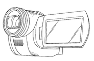
- FIG. 8 is a diagram illustrating an example of an imaging apparatus equipped with the information processing apparatus according to the present invention.
- FIG. 2 is a diagram showing a main block configuration of the imaging system according to the present invention
- FIG. 3 is a diagram showing a main functional configuration of the imaging system according to the present invention.
- the image capturing apparatus 101 is a moving image recording apparatus such as a camera or a camcorder, for example, and captures a video clip (captured image group) by capturing a plurality of images. Specifically, the photographing apparatus 101 records a video clip (captured image group) by repeatedly starting and stopping recording in accordance with a photographer's instruction.
- the recording medium 105 is a recordable medium such as an SD memory, HDD, CD-R, or DVD-R, for example, and data (here, image data) is recorded by the information processing apparatus 100.
- the information processing apparatus 100 shown in FIG. 2 encodes and records a plurality of video clips shot by repeating the start and stop of shooting a plurality of times in the shooting apparatus 101. Specifically, the information processing apparatus 100 encodes an image input from the photographing apparatus 101 by a technique such as MPEG2 or H264, and records the encoded image on the recording medium 105, for example. Note that a video clip is composed of a plurality of captured images.
- the information processing apparatus 100 illustrated in FIG. 2 includes a video clip holding unit 102, an encoding processing unit 103, a stream buffer 104, a clip end image holding unit 201, a blending unit 202, a synchronization control unit 203, a blend And a control unit 204.
- the video clip holding unit 102 holds a video clip composed of the number of shot images shot by the shooting device 101.
- the image signal photographed by the photographing apparatus 101 is subjected to signal processing and held as a photographed image signal.
- the video clip holding unit 102 holds image information for a processing unit sufficient to encode the end image information at a timing when a stop instruction is given to the photographing apparatus 101 by the photographer.
- the image information for the processing unit sufficient to encode the end image information is, for example, a plurality of times corresponding to a minimum unit (1 GOP) or more composed of pictures having a reference relationship with the clip end image. A plurality of captured images such as 1 GOP after a stop instruction.
- the video clip holding unit 102 may hold one video clip obtained from the start to the stop of shooting of the shooting apparatus 101, and is shot by repeating the start and stop of shooting of the shooting apparatus 101 a plurality of times. A plurality of video clips may be held.
- the clip end image holding unit 201 holds a terminal shot image as a clip end image among one video clip obtained from the start to the stop of shooting by the shooting apparatus 101.
- the clip end image holding unit 201 corresponds to a processing unit sufficient for the video clip holding unit 102 to encode the end image information at a timing when a stop instruction is given to the photographing apparatus 101 by the photographer. After the image information is held, the next one frame of image information is held as a clip end image signal (clip end image).
- the clip end image signal may be, for example, a plurality of captured images for a time equal to or longer than the minimum unit (1 GOP) composed of pictures having a reference relationship with the clip end image.
- the clip end image signal (clip end image) is, for example, a final shot image of video clips (a plurality of shot images) obtained from the start to the stop of shooting by the shooting apparatus 101, and is equivalent to one frame. It may be a still image.
- the synchronization control unit 203 controls the clip end image holding unit 201 and the video clip holding unit 102 to input the clip end image from the clip end image holding unit 201. Then, synchronization with the input of the photographed image taken at the start time of the next photography from the video clip holding unit 102 is performed.
- the synchronization control unit 203 receives the captured image signal with the actual time input from the image capturing apparatus 101 to the video clip holding unit 102 and the clip end point in response to a recapture start instruction (capture resumption instruction) by the photographer.
- the clip end image signal held in the image holding unit 201 is synchronized with the two inputs.
- the two inputs are sent to the blend unit 202.
- the blend unit 202 includes a blend execution unit 2021 and a frame buffer 2022, and blends (superimposes) the input image to generate image data. Specifically, when resuming shooting (starting the next shooting), the blending unit 202 uses the clip end image input in synchronization by the synchronization control unit 203 and the shot image shot at the shooting restart point, Image data is generated by blending according to the control information. That is, the blending unit 202 receives the clip end image and the shot image shot at the start of the next shooting, and inputs the clip end image and the shot image shot at the start of the next shooting. Blend to generate image data.
- the blend execution unit 2021 is controlled by the control information output from the blend control unit 204, and blends the two inputs according to the weighted superimposition ratio (value ⁇ indicating the blend ratio) indicated in the control information to generate image data. Is generated.
- the blend execution unit 2021 stores the generated image data in the frame buffer 2022. Specifically, as shown in FIG. 3, the blend execution unit 2021 converts the captured image held by the video clip holding unit 102 and the clip end image held by the clip end image holding unit 201 to ⁇ : (1- Mix at a ratio of ⁇ ), that is, blend (superimpose).
- the value ⁇ indicating the blend ratio takes a value from 0 to 1.
- the blend execution unit 2021 blends only the clip end image held in the clip end image holding unit 201 out of the two inputs, and blends the image data of only the clip end image. Generated as later video information.
- the blend ratio indicates a value of 1
- only the captured image held by the video clip holding unit 102 is blended, and image data of only the captured image is generated as the video information after blending.
- the value ⁇ indicating the blend ratio is determined by the value of ⁇ that can be taken when starting the next shooting (resuming the shooting), the clip end image, and the shot image shot at the next shooting start time. The ratio of blending is determined.
- the value ⁇ indicating the blend ratio may be initialized to 0 by a re-shooting start instruction from the photographer, and the value ⁇ indicating the blend ratio is initialized to 0 by a shooting stop instruction from the photographer. It may be done.
- the value ⁇ indicating the blend ratio may be set to 1.
- white data separately prepared in advance by the clip end image holding unit 201 using ROM data or the like And / or a fixed image such as black may be blended.
- the clip end image can be blended in a stepwise manner with the shot image taken at the next start of shooting.
- the value ⁇ indicating the blend ratio may be changed based on, for example, control information including a code amount. In that case, by controlling the rate of change in the blend ratio, it is possible to suppress the generation of an unnecessary code amount from the relevance of the image, and to further suppress the buffer failure during seamless reproduction.
- the frame buffer 2022 stores the image data generated by the blend execution unit 2021.
- the stored image data is read out by the encoding processing unit 103 during the encoding process.
- the blend control unit 204 controls the blend unit 202 with control information. Specifically, the blend control unit 204 determines the control information based on the code amount calculated by the code amount control unit 1031 and the image correlation between the clip end image and the captured image immediately before the clip end image. decide. Then, according to the determined control information, the blend unit 202 changes the ratio of blending the clip end image and the photographed image taken at the next photographing start time to generate image data.
- the blend control unit 204 may determine control information based on a code amount preset in the information processing apparatus 100, for example. Further, the blend control unit 204, for example, when the clip end image holding unit 201 holds the clip end image, the control information is obtained based on the code amount calculated by the code amount control unit 1031 of the clip end image. It may be decided. Also, the blend control unit 204 uses the information on the current code amount calculated by the code amount control unit 1031, for example, to the blend unit 202, and the captured image captured at the time when the next capturing starts. The image data may be generated by changing the blend ratio.
- the encoding processing unit 103 includes a code amount control unit 1031, a quantization unit 1032, and an encoding unit 1033.
- the encoding processing unit 103 encodes the image data generated by the blend unit 202 and encodes it based on the control information. Controls the code amount of image data.
- the code amount control unit 1031 controls the code amount of the image data encoded by the encoding processing unit 103 based on the control information. Specifically, the code amount control unit 1031 controls the code amount encoded by the encoding unit 1033 according to the control information at the start of the next shooting, and from the start of shooting of the shooting apparatus 101 to the stop thereof. The amount of code encoded by the encoding unit 1033 is controlled for each encoding processing unit without depending on the control information.
- the encoding unit 1033 encodes the image data generated by the blending unit 202. Specifically, the encoding unit 1033 encodes the image data generated by the blend unit 202 with the code amount controlled by the code amount control unit 1031 at the start of the next imaging, and the imaging device 101 performs imaging. From the start to the stop, the blend unit is obtained by blending only a plurality of photographed images taken after the start of the next photographing input to the blend unit 202 with the code amount controlled by the code amount control unit 1031. The image data generated in 202 is encoded.
- the code amount may be a small code amount set in advance, or may be a code amount obtained by the code amount control unit 1031 calculating the code amount of the clip end image in advance. Also good.
- the stream buffer 104 temporarily stores a plurality of video clips encoded in a format that can be recorded on the recording medium 105 by the encoding processing unit 103.
- the plurality of encoded video clips temporarily stored are recorded on the recording medium 105.
- the information processing apparatus 100 configured as described above includes a video clip holding unit 102 that holds a shot image signal input from the shooting apparatus 101, a clip end image holding unit 201 that holds a clip end image signal, and a clip end point.
- Blend unit 202 having as input the clip end image signal of image holding unit 201 and the captured image signal of video clip holding unit 102, synchronization control unit 203 that synchronizes the two inputs, and blend that controls blend unit 202
- the encoding unit 103 includes a control unit 204 and an encoding processing unit 103.
- the encoding processing unit 103 includes a code amount control unit 1031 that controls the code amount based on control information of the blend control unit 204, and then starts shooting ( It is characterized by recording the image data (video) generated by blending the captured image and the clip end image at the time of shooting resumption) .
- a code amount control unit 1031 that controls the code amount based on control information of the blend control unit 204, and then starts shooting ( It is characterized by recording the image data (video) generated by blending the captured image and the clip end image at the time of shooting resumption) .
- video is a video recording method that is continuous with the time axis, not the moment, so the photographer can take multiple shot images (video clips) from the start of shooting (recording start) to the stop of shooting. Recording is performed while repeating the start and stop operations of shooting.
- the clip end image is video information of one frame, 1 GOP or 1 GOP or more after the shooting stop instruction of the photographer, a plurality of shot images (video clips) up to the shooting stop instruction of the photographer are stored on the hard disk.
- a storage medium such as a semiconductor memory.
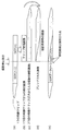
- FIG. 4 is a diagram for explaining a captured image information processing method that enables seamless playback of the information processing apparatus according to the present invention.
- the photographed image (image data) until being encoded and stored in the recording medium 105 according to the photographing stop instruction by the photographer is the (n ⁇ 1) th (n is a natural number), the photographing start instruction (shooting restart instruction)
- the clip end image to be superimposed is set to the nth (n is a natural number) of the captured image (image data).
- the video clip holding unit 102 has a processing unit sufficient to encode the end image information at the timing when the photographing apparatus is instructed to stop photographing by the photographer.
- Image information that is, a video clip up to a photographed image (n-1) photographed by the photographing apparatus 101 and a photographed image (n) which is image information of the next one frame are held.
- the clip end image holding unit 201 is configured so that the video clip holding unit 102 takes the shot image (n ⁇ 1) at the timing when the shooting is instructed to the shooting apparatus 101 by the photographer. After that, the image information of the next one frame, that is, the captured image (n) is held as the clip end image.
- (c) of FIG. 4 shows that the video clip holding unit 102 has a plurality of images captured by the imaging device 101 at the timing when the next imaging start instruction (imaging restart instruction) is given to the imaging device 101 by the photographer. A photographed image (video clip to be held from now on) is shown.
- the blend unit 202 synchronizes and inputs the captured image (when the photographer next instructs the photographing apparatus 101 to perform photographing start (shooting restart instruction) when the photographing is started next (photographing restart instruction).
- the clip end image of n) and the shot image shot at the shooting start time (shooting restart time) are blended according to the value ⁇ indicating the blend ratio indicated in the control information, as shown in FIG. Then, the encoding processing unit 103 generates image data as shown in FIG.
- the information processing apparatus 100 can correlate images with respect to parts such as scene changes.
- the clip end image (clip end image signal) is one frame of still image information immediately after the shooting stop instruction.
- the present invention is not limited to this.
- An integer multiple of 1 GOP which is a processing unit of a plurality of captured images for a time equal to or longer than a minimum unit (1 GOP) composed of a plurality of pictures in which a clip end image (clip end image signal) has a reference relationship with the clip end image Video information.
- FIG. 5 is a diagram for explaining an information processing method for captured images that enables seamless reproduction of the information processing apparatus according to the present invention.
- FIG. 5 shows a case where the clip end image (signal) is video information that is an integral multiple of 1 GOP. That is, a video in which a clip end image (clip end image signal) maintains a correlation between frames (captured images) in units of GOPs, which are a plurality of pictures as a minimum unit that establishes a reference relationship necessary for image compression processing. The case of information is shown.
- n ⁇ 1th n is a natural number of GOP (GOP data).
- the clip end image which is the moving image information of an integral multiple of 1 GOP, to be superimposed by the next shooting start instruction (shooting restart instruction) is set to the nth (n is a natural number) of the GOP (GOP data).
- the video clip holding unit 102 has a processing unit sufficient to encode the end image information at the timing when the photographing apparatus is instructed to stop the photographing apparatus 101.
- Image information that is, a plurality of photographed images (video clips) up to GOP (n ⁇ 1) photographed by the photographing apparatus 101 and GOP (n) which is the next GOP are held.
- the clip end image holding unit 201 causes the video clip holding unit 102 to set GOP (n ⁇ 1) at the timing when the shooting is instructed to the shooting apparatus 101 by the photographer. After holding, the next GOP, that is, GOP (n) is held as the clip end image.
- (c) of FIG. 5 shows that the video clip holding unit 102 has a plurality of images captured by the imaging apparatus 101 at the timing when the next imaging start instruction (imaging restart instruction) is given to the imaging apparatus 101 by the photographer. A photographed image (video clip to be held from now on) is shown.
- the blending unit 202 synchronizes and inputs the GOP (n) when the next photographing is started, that is, at the timing when the photographer gives the photographing device 101 a next photographing start instruction (shooting restart instruction). ) And the shot end image taken at the next shooting start time (shooting restart time), as shown in FIG. 5D, are blended according to the value ⁇ indicating the blend ratio indicated in the control information. . Then, the encoding processing unit 103 generates GOP data (image data) as shown in FIG.
- the information processing apparatus 100 can have image correlation with respect to a part such as a scene change by being blended from the nth GOP and encoded later.
- FIG. 6 is a flowchart for explaining the information processing method of the imaging system according to the present invention.
- the initial blend ratio is set.
- the blending unit 202 starts blending
- the encoding processing unit 103 starts encoding (S103).
- changing the blend amount means changing the blend ratio by adding or subtracting the value ⁇ indicating the blend ratio in increments of 0.1, for example.
- the photographing stop (recording stop) instruction is monitored, that is, whether or not the photographing is finished (S106). If a shooting stop instruction is issued by the photographer (YES in S106), processing sufficient for the video clip holding unit 102 to encode the end image information at the timing when the shooting instruction is given to the shooting apparatus 101 by the photographer. After holding the image information for the unit, the next one frame of image information is held as a clip end image.
- the photographing stop instruction by the photographer is further monitored in the same manner as described above (S106).
- the video clip holding unit 102 holds image information for a processing unit sufficient to encode the above-described end image information at the timing when the photographing apparatus 101 instructs the photographing apparatus 101 to stop. Then, the image information of the next one frame is held as a clip end image (S107).
- the blending process can be performed by the above series of processing flows.
- the correlation between image contents may be low between adjacent pictures, such as a scene change.
- the amount of generated codes to be allocated increases unnecessarily, and the virtual buffer for code amount smoothing may overflow, which is one factor that makes seamless reproduction extremely difficult.
- the CC 5 connection method of the AVCHD standard as means for solving this, that is, the code of the image after the scene change based on the coding amount of the image before the scene change and the buffer remaining amount at the time of decoding (decoding) Even if the amount of code is limited so that the buffer does not overflow during playback, the amount of code cannot be sufficiently allocated for the amount of code originally intended to be allocated, resulting in fatal image quality degradation. There was a risk of inviting.
- the recording resumption position (the next shooting start position) after the recording is stopped (after the shooting is stopped)
- the clip end image and the video clip at the time of the recording restart (the next shooting start).
- a clip end image relative to the beginning of the video clip at the time of resuming recording that is, the shot image after the shooting is stopped and shot at the time when the shooting is resumed.
- the encoding processing unit 103 includes a code amount control unit 1031 that controls the code amount based on the control information of the blend control unit 204.
- the code amount control unit 1031 when encoding the image data that has been blended and generated immediately after the recording resumption instruction (shooting resumption instruction), specifies, for example, a small code amount set in advance.
- the encoding unit 1033 performs encoding processing. Thereby, not only there is no buffer overflow at the time of reproduction, but also seamless reproduction can be realized without causing image quality degradation.
- the code amount control unit 1031 may calculate the code amount of the clip end image in advance and use it as the code amount after the recording restart instruction. good.
- the information processing apparatus and information processing method of the present invention it is possible to avoid the discontinuity of the video information by maintaining the correlation between the video clips. It becomes unnecessary to be aware of the processing on the code side. Accordingly, seamless reproduction can be realized easily at a low cost.
- the information processing apparatus and the information processing method of the present invention in seamless playback between video clips, editing using an expensive editing device is unnecessary, and a video effect with a high crossfade is obtained at the same time as shooting is completed. Can be provided. Further, the effect can be obtained without changing the basic operation flow performed when the photographer shoots a moving image. Furthermore, it can be realized by a combination of the functions that are the basis of the moving image photographing device, and has an effect that it can be obtained relatively easily, inexpensively, and extremely high effects.
- a management unit that manages the head position immediately after the image data of the blended part (joined part) as a playlist of the AVCHD standard And the management unit may select the head position by managing the time information of the head positions.
- the information processing apparatus and the information processing method of the present invention have been described based on the embodiment, but the present invention is not limited to this embodiment. Unless it deviates from the meaning of this invention, the form which carried out the various deformation
- This imaging device is, for example, a camera (digital still camera) as shown in FIG. 7 or a camcorder as shown in FIG. 8, and captures a desired scene by repeating recording and pause (shooting start and shooting stop). Can be recorded.
- the present invention can be used for an information processing device and an information processing method, and is particularly used for home photographing using a photographing device such as a camera or a camcorder, and is desired by repeatedly recording and pausing (starting photographing and stopping photographing). It can be used in an information processing apparatus and an information processing method for photographing and recording a scene.
Abstract
Même lors des changements de scène, le dispositif de traitement d'informations selon l'invention permet de contrôler facilement et convenablement la quantité de données produites dans un processus d'encodage. Ledit dispositif de traitement d'informations (100), qui permet aussi une lecture homogène facile, comporte une unité de mémorisation de bande vidéo (102), une unité de mémorisation d'image de fin de bande (201), une unité de mélange (202), et une unité de traitement d'encodage (103). L'unité de mémorisation de bande vidéo (102) mémorise une bande vidéo comprenant une pluralité d'images prises. L'unité de mémorisation d'image de fin de bande (201) mémorise une image de fin de bande qui est la dernière image prise à partir d'une seule bande vidéo depuis le début jusqu'à la fin de la visualisation par un dispositif de visualisation. L'image de fin de bande et une image prise au début de la visualisation suivante sont entrées dans l'unité de mélange (202) qui mélange lesdites images pour générer des données d'image. L'unité de traitement d'encodage (103) encode les données d'image générées par l'unité de mélange (202), et sur la base d'informations de commande, commande la taille des données d'image encodées.
Applications Claiming Priority (2)
| Application Number | Priority Date | Filing Date | Title |
|---|---|---|---|
| JP2010-095525 | 2010-04-16 | ||
| JP2010095525 | 2010-04-16 |
Publications (1)
| Publication Number | Publication Date |
|---|---|
| WO2011129059A1 true WO2011129059A1 (fr) | 2011-10-20 |
Family
ID=44798448
Family Applications (1)
| Application Number | Title | Priority Date | Filing Date |
|---|---|---|---|
| PCT/JP2011/001725 WO2011129059A1 (fr) | 2010-04-16 | 2011-03-24 | Dispositif de traitement d'informations et procédé de traitement d'informations |
Country Status (1)
| Country | Link |
|---|---|
| WO (1) | WO2011129059A1 (fr) |
Citations (5)
| Publication number | Priority date | Publication date | Assignee | Title |
|---|---|---|---|---|
| JP2003319259A (ja) * | 2002-04-24 | 2003-11-07 | Matsushita Electric Ind Co Ltd | 映像効果制御装置及び映像効果制御方法 |
| JP2004120544A (ja) * | 2002-09-27 | 2004-04-15 | Fuji Photo Film Co Ltd | 画像編集装置、画像編集プログラム並びに画像編集方法 |
| JP2004248139A (ja) * | 2003-02-17 | 2004-09-02 | Matsushita Electric Ind Co Ltd | 撮像記録装置 |
| JP2007088932A (ja) * | 2005-09-22 | 2007-04-05 | Matsushita Electric Ind Co Ltd | 映像音声記録装置及び映像音声記録方法 |
| JP2007306258A (ja) * | 2006-05-10 | 2007-11-22 | Sony Corp | 情報処理装置、および情報処理方法、並びにコンピュータ・プログラム |
-
2011
- 2011-03-24 WO PCT/JP2011/001725 patent/WO2011129059A1/fr active Application Filing
Patent Citations (5)
| Publication number | Priority date | Publication date | Assignee | Title |
|---|---|---|---|---|
| JP2003319259A (ja) * | 2002-04-24 | 2003-11-07 | Matsushita Electric Ind Co Ltd | 映像効果制御装置及び映像効果制御方法 |
| JP2004120544A (ja) * | 2002-09-27 | 2004-04-15 | Fuji Photo Film Co Ltd | 画像編集装置、画像編集プログラム並びに画像編集方法 |
| JP2004248139A (ja) * | 2003-02-17 | 2004-09-02 | Matsushita Electric Ind Co Ltd | 撮像記録装置 |
| JP2007088932A (ja) * | 2005-09-22 | 2007-04-05 | Matsushita Electric Ind Co Ltd | 映像音声記録装置及び映像音声記録方法 |
| JP2007306258A (ja) * | 2006-05-10 | 2007-11-22 | Sony Corp | 情報処理装置、および情報処理方法、並びにコンピュータ・プログラム |
Similar Documents
| Publication | Publication Date | Title |
|---|---|---|
| KR100906957B1 (ko) | 서브-프레임 메타데이터를 이용한 적응 비디오 프로세싱 | |
| TWI400939B (zh) | 一種視頻播放器電路及視頻顯示方法 | |
| JP4791129B2 (ja) | 画像符号化装置、画像符号化方法及び画像編集装置 | |
| JP3529599B2 (ja) | 符号化装置における編集可能点挿入方法および符号化装置 | |
| JP2010035133A (ja) | 動画像符号化装置及び動画像符号化方法 | |
| JP5284074B2 (ja) | 画像処理装置及び画像処理方法 | |
| WO2003067881A1 (fr) | Appareil de traitement d'informations et procede associe | |
| JP2007158432A (ja) | 映像記録装置 | |
| KR20040010155A (ko) | 화상 데이터 재생 장치 및 방법 | |
| WO2011129059A1 (fr) | Dispositif de traitement d'informations et procédé de traitement d'informations | |
| JP2003052040A (ja) | Mpegデータ再生装置 | |
| JP2003052010A (ja) | Mpegデータ記録方法 | |
| JP2011049927A (ja) | 画像処理装置、およびそれを搭載した撮像装置 | |
| JP2008258858A (ja) | 動画像符号化装置 | |
| JP3897783B2 (ja) | 画像処理装置及びその制御方法、並びにコンピュータプログラム及びコンピュータ可読記憶媒体 | |
| WO2004006573A1 (fr) | Dispositif et traitement de donnees d'image | |
| JPH10108200A (ja) | 画像符号化方法およびその装置 | |
| JP2007097146A (ja) | 印刷要求タイミングに応じた静止画印刷方法及び装置 | |
| JP2008005520A (ja) | Mpegデータ記録再生装置 | |
| JP5084586B2 (ja) | 画像記録再生装置及び画像再生装置 | |
| JP5825976B2 (ja) | 符号化装置及び方法 | |
| JP2007325304A (ja) | Mpegデータ記録再生方法 | |
| JP2006135446A (ja) | ストリーム再生装置 | |
| JP2007300443A (ja) | サムネイル作成装置 | |
| JP2011040827A (ja) | 映像収録再生装置及び映像クリップ処理方法 |
Legal Events
| Date | Code | Title | Description |
|---|---|---|---|
| 121 | Ep: the epo has been informed by wipo that ep was designated in this application |
Ref document number: 11768586 Country of ref document: EP Kind code of ref document: A1 |
|
| NENP | Non-entry into the national phase |
Ref country code: DE |
|
| 122 | Ep: pct application non-entry in european phase |
Ref document number: 11768586 Country of ref document: EP Kind code of ref document: A1 |
|
| NENP | Non-entry into the national phase |
Ref country code: JP |