WO2011125664A1 - 射出成形用金型、樹脂成形品の製造方法、樹脂成形品および自動車両 - Google Patents
射出成形用金型、樹脂成形品の製造方法、樹脂成形品および自動車両 Download PDFInfo
- Publication number
- WO2011125664A1 WO2011125664A1 PCT/JP2011/057865 JP2011057865W WO2011125664A1 WO 2011125664 A1 WO2011125664 A1 WO 2011125664A1 JP 2011057865 W JP2011057865 W JP 2011057865W WO 2011125664 A1 WO2011125664 A1 WO 2011125664A1
- Authority
- WO
- WIPO (PCT)
- Prior art keywords
- molded product
- resin molded
- gate
- resin
- cavity
- Prior art date
- Legal status (The legal status is an assumption and is not a legal conclusion. Google has not performed a legal analysis and makes no representation as to the accuracy of the status listed.)
- Ceased
Links
Images








Classifications
-
- B—PERFORMING OPERATIONS; TRANSPORTING
- B29—WORKING OF PLASTICS; WORKING OF SUBSTANCES IN A PLASTIC STATE IN GENERAL
- B29C—SHAPING OR JOINING OF PLASTICS; SHAPING OF MATERIAL IN A PLASTIC STATE, NOT OTHERWISE PROVIDED FOR; AFTER-TREATMENT OF THE SHAPED PRODUCTS, e.g. REPAIRING
- B29C45/00—Injection moulding, i.e. forcing the required volume of moulding material through a nozzle into a closed mould; Apparatus therefor
- B29C45/0046—Details relating to the filling pattern or flow paths or flow characteristics of moulding material in the mould cavity
-
- B—PERFORMING OPERATIONS; TRANSPORTING
- B29—WORKING OF PLASTICS; WORKING OF SUBSTANCES IN A PLASTIC STATE IN GENERAL
- B29C—SHAPING OR JOINING OF PLASTICS; SHAPING OF MATERIAL IN A PLASTIC STATE, NOT OTHERWISE PROVIDED FOR; AFTER-TREATMENT OF THE SHAPED PRODUCTS, e.g. REPAIRING
- B29C45/00—Injection moulding, i.e. forcing the required volume of moulding material through a nozzle into a closed mould; Apparatus therefor
- B29C45/0046—Details relating to the filling pattern or flow paths or flow characteristics of moulding material in the mould cavity
- B29C2045/0049—Details relating to the filling pattern or flow paths or flow characteristics of moulding material in the mould cavity the injected material flowing against a mould cavity protruding part
Definitions
- the present invention relates to an injection mold for producing a resin molded product by injection molding.
- the present invention also relates to a resin molded product and a manufacturing method thereof.
- ABS (Acrylonitrile-Butadiene-Styrene) resin has an excellent balance of mechanical properties such as rigidity, hardness, workability, impact resistance, and bending fatigue resistance.
- the ABS resin can emphasize desired characteristics by adjusting the blending ratio of the raw materials.
- the ABS resin is excellent in terms of cost. Since ABS resin has the above-mentioned advantages, it is widely used as a material for components such as motor vehicles and home appliances. Many of the components made of ABS resin are resin molded products manufactured by injection molding (see, for example, Patent Document 1).
- Resin molded products are painted to enhance the decorativeness.
- metallic coating in addition to the most common solid coating, metallic coating having a metallic luster is known.
- a paint containing fine metal pieces for example, aluminum flakes
- a paint for metallic coating is disclosed in Patent Document 2, for example.
- Metallic paint can give a sense of luxury.
- Suikomi is thought to be caused by shear stress generated in the resin material during injection molding.
- FIGS. 9 to 13 a mechanism that is presumed to be the cause of watermelon occurrence will be described.
- FIG. 9A is a diagram showing a cross-sectional structure near the surface of the resin molded product before painting, and shows a region near the gate.
- FIG. 9B is a photomicrograph showing the same region.
- the ABS resin has a structure in which particles 2 of butadiene rubber are dispersed in a matrix 1 of AS (acrylonitrile-styrene) resin.
- AS acrylonitrile-styrene
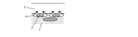
- the coating 3 ′ (including a fine metal piece as described later) is applied to the surface of such a resin molded product, the AS resin matrix 1 is added to the solvent of the coating 3 ′. Since it is attacked, the stretched butadiene rubber particles 2 are restored. Therefore, a void 4 is formed between the butadiene rubber particles 2 and the AS resin matrix 1.
- FIG. 12 (a) is a photograph showing a resin molded product in which no watermelon is accidentally generated
- FIG. 12 (b) is a photograph showing a resin molded product in which watermelon is generated
- FIG. 13A is an FE-SEM (field emission scanning electron microscope) photograph showing the cross-sectional structure of the resin molded product shown in FIG. 12A
- FIG. 2 is an FE-SEM photograph showing a cross-sectional structure of the resin molded product shown in FIG.
- the coating film 3 shown in FIGS. 13A and 13B has a two-layer structure including a metallic layer (base coat layer) 3A including a metal piece 3a and a top coat layer 3B formed on the metallic layer. Have. By providing the topcoat layer 3B, the metal piece 3a can be prevented from being oxidized.
- a resin molded product formed from a resin material containing a rubber component may cause a coating failure called watermelon, which causes an increase in manufacturing cost.
- the present invention has been made in view of the above problems, and an object of the present invention is to suppress the occurrence of water droplets when a resin molded product is manufactured by injection molding.
- An injection mold according to the present invention is an injection mold for manufacturing a resin molded product by injection molding, and includes a first mold plate and a second mold plate arranged to face each other. A cavity and a gate connected to the cavity are defined between the first template and the second template, and the first template molds the surface of the resin molded product.
- the second mold plate has a second cavity surface for molding the back surface of the resin molded product, and the second cavity surface is a wall portion protruding toward the cavity side,
- the wall portion has a wall portion close to the gate, and the length of the wall portion along a first direction parallel to the width direction of the gate is larger than the width of the gate and along the first direction. It is smaller than the length of the second cavity surface.
- the length of the wall portion is not less than 1.5 times and not more than 10 times the width of the gate.
- the distance from the gate to the wall is 0 mm or more and 10 mm or less.
- the height of the wall portion is not less than 25% and not more than 75% of the thickness of the resin molded product.
- a width of the wall portion along a second direction orthogonal to the first direction is 50 mm or less.
- the wall portion includes a first side surface that intersects the second direction and a second side surface that intersects the second direction, and is opposite to the gate with respect to the first side surface. And a second side surface located at the top.
- the first side surface of the wall portion has a draft angle of more than 0 ° and not more than 45 °.
- the second side surface of the wall portion has a draft angle of more than 0 ° and not more than 45 °.
- a cross-sectional shape of the wall portion along a plane perpendicular to the height direction is substantially rectangular.
- a method for producing a resin molded product according to the present invention is a method for producing a resin molded product using an injection mold having the above-described configuration, the step of melting a resin material, and the injection of the molten resin material. A step of filling the cavity of the molding die through the gate; and a step of cooling and solidifying the resin material in the cavity.
- the resin material includes a rubber component.
- the resin material is an ABS resin or an AES resin.
- the method for producing a resin molded product according to the present invention includes a step of taking a solidified resin material from the cavity to obtain a resin molded product, and a step of applying a metallic coating to the surface of the resin molded product. are further included.
- the resin molded product according to the present invention is a resin molded product having a front surface and a back surface, and at least the surface is coated with a metallic coating, the back surface having a recess close to a gate cut mark, and the gate cut
- the length of the concave portion along the first direction parallel to the width direction of the trace is larger than the width of the gate cut trace and smaller than the length of the back surface along the first direction.
- the length of the concave portion is not less than 1.5 times and not more than 10 times the width of the gate cut trace.
- the distance from the gate cut trace to the recess is 0 mm or more and 10 mm or less.
- the depth of the recess is 25% or more and 75% or less of the thickness of the resin molded product.
- a width of the concave portion along a second direction orthogonal to the first direction is 50 mm or less.
- a cross-sectional shape of the concave portion along a plane orthogonal to the depth direction is substantially rectangular.
- the resin molded product according to the present invention is formed from a resin material containing a rubber component.
- the resin material is an ABS resin or an AES resin.
- the motor vehicle according to the present invention includes a resin molded product having the above-described configuration.
- One (first mold plate) of a pair of mold plates provided in the injection mold according to the present invention has a first cavity surface for molding the surface of a resin molded product, and the other (second mold plate). ) Has a second cavity surface for molding the back surface of the resin molded product.
- the second cavity surface has a wall portion that protrudes toward the cavity and is close to the gate.
- the length of the wall portion along the first direction parallel to the width direction of the gate is larger than the width of the gate and the second cavity along the first direction. It is smaller than the length of the surface. Therefore, the flow rate of the resin material immediately after flowing into the cavity can be sufficiently reduced, and the rapid filling of the resin material into the entire cavity is not hindered.
- the length of the wall is preferably at least 1.5 times the width of the gate from the viewpoint of sufficiently reducing the flow rate of the resin material to sufficiently reduce the shear stress, and the resin material to the entire cavity. From the standpoint of not hindering the rapid filling of the gate, it is preferably not more than 10 times the width of the gate.
- the distance from the gate to the wall is preferably 0 mm or more and 10 mm or less. If the distance from the gate to the wall exceeds 10 mm, the effect of reducing the flow rate of the resin material may be small.
- the height of the wall portion is 25% or more of the thickness of the resin molded product (the thickness of the cavity near the wall portion) from the viewpoint of sufficiently reducing the flow rate of the resin material and sufficiently reducing the shear stress. It is preferable that it is 75% or less from the viewpoint of not hindering the rapid filling of the resin material into the entire cavity.
- the wall width of the wall portion along the second direction orthogonal to the first direction that is, the direction orthogonal to the width direction of the gate
- the wall width is preferably 50 mm or less.
- the wall portion includes a first side surface that intersects the second direction, a second side surface that intersects the second direction, and a second side surface that is located on the opposite side of the gate from the first side surface.
- the first side surface and / or the second side surface of the wall portion preferably has a draft angle of more than 0 ° and not more than 45 °.
- the cross-sectional shape of the wall portion along the plane orthogonal to the height direction is preferably substantially rectangular. If the cross-sectional shape of the wall is circular, the effect of reducing the flow rate of the resin material may be small.
- the method for producing a resin molded product according to the present invention uses an injection mold having the above-described configuration, it is possible to suppress the occurrence of watermelon. Therefore, it is not necessary to repaint, and the manufacturing cost can be reduced.
- the resin material containing the rubber component is, for example, ABS resin or AES resin.
- the method for producing a resin molded product according to the present invention is suitably used when a metallic coating is applied to the surface of the resin molded product.
- the resin molded product according to the present invention has a front surface and a back surface, and at least the surface is coated with metallic paint.
- the back surface of the resin molded product according to the present invention has a recess close to the gate cut mark. This concave portion is formed corresponding to a wall portion (which is naturally close to the gate) provided on the cavity surface of the injection mold. Therefore, when manufacturing a resin molded product provided with such a recess, the flow rate of the resin material immediately after flowing from the gate into the cavity is reduced by the wall, so that the shear stress generated in the resin material is reduced. The size can be reduced. Therefore, it is possible to suppress the occurrence of water droplets due to shear stress.
- the length of the concave portion along the first direction parallel to the width direction of the gate cut trace is larger than the width of the gate cut trace and the back surface along the first direction. Less than length.
- the length of the wall portion of the injection mold must be larger than the width of the gate and smaller than the length of the second cavity surface along the first direction. is there. Therefore, when the resin molded product according to the present invention is manufactured, the flow rate of the resin material immediately after flowing into the cavity can be sufficiently reduced, and the rapid filling of the resin material into the entire cavity can be prevented. Absent.
- the length of the recess (corresponding to the length of the wall of the injection mold) is sufficiently low in the flow rate of the resin material to reduce the shear stress sufficiently, so that the width of the gate cut mark is
- the width is preferably 1.5 times or more, and preferably 10 times or less the width of the gate cut trace from the viewpoint of preventing the rapid filling of the resin material into the entire cavity.
- the distance from the gate cut trace to the recess (corresponding to the distance from the gate of the injection mold to the wall) is preferably 0 mm or more and 10 mm or less. If the distance from the gate cut trace to the recess exceeds 10 mm, the effect of reducing the flow rate of the resin material may be small.
- the depth of the recess (corresponding to the height of the wall of the injection mold) is sufficient to reduce the flow rate of the resin material and sufficiently reduce the shear stress, so that the thickness of the resin molded product Is preferably 25% or more, and is preferably 75% or less from the viewpoint of not preventing rapid filling of the resin material into the entire cavity.
- the width of the recess is preferably 50 mm or less.
- the cross-sectional shape along the plane perpendicular to the depth direction of the recess (corresponding to the cross-sectional shape along the plane perpendicular to the height direction of the wall portion of the mold for injection molding) may be substantially rectangular. preferable. If the cross-sectional shape of the recess is circular, the effect of reducing the flow rate of the resin material may be small.
- Watermelon is generated when the resin material contains a rubber component. Therefore, this invention is used suitably for the resin molded product formed from the resin material containing a rubber component.
- the resin material containing the rubber component is, for example, ABS resin or AES resin.
- the resin molded product according to the present invention is suitably used as a member of an automobile (for example, an exterior member).
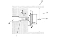
- FIG. 2 is a cross-sectional view schematically showing the vicinity of a wall portion 22 of an injection mold 100.
- FIG. It is a top view which shows typically the 2nd template 20 with which the metal mold
- (A)-(c) is a figure which shows typically the resin molded product 200 in suitable embodiment of this invention.
- (A) is a perspective view
- (b) is a plan view of the resin molded product 200 as viewed from below
- (c) is a cross-sectional view taken along line 4C-4C 'in (b). It is a photograph which shows the example of the resin molded product 200 actually manufactured.
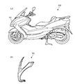
- FIG. 1 is a side view schematically showing the motorcycle 300
- FIG. 2 is a perspective view schematically showing a front cover for the motorcycle 300.
- FIG. It is a perspective view which shows typically the front cover 301 before the gate part 32a, the runner part 36a, and the sprue part 34a are cut
- A) is a figure which shows typically the cross-sectional structure of the surface vicinity of the resin molded product before coating, and has shown the area
- (B) is a photomicrograph showing the same region. It is a figure which shows typically the cross-sectional structure when the coating material 3 'is provided to the resin molded product shown in FIG.
- FIG. 12 A is a photograph showing a resin molded product in which no watermelon is accidentally generated, and (b) is a photograph showing a resin molded product in which watermelon is generated.
- A) is an FE-SEM photograph showing a cross-sectional structure of the resin molded product shown in FIG. 12 (a), and (b) is an FE-SEM showing a cross-sectional structure of the resin molded product shown in FIG. 12 (b). It is a photograph.
- FIG. 1 shows an injection mold (hereinafter, also simply referred to as “mold”) 100 according to the present embodiment.
- FIG. 1 is a cross-sectional view schematically showing a mold 100 in a clamped state.
- the mold 100 includes a first template 10 and a second template 20 that are arranged to face each other.
- a cavity 30 and a gate 32 connected to the cavity 30 are defined between the first template 10 and the second template 20.
- the cavity 30 is a space where a resin material is molded (that is, has the same shape as a resin molded product).
- the gate 32 is an inlet for guiding the molten resin material to the cavity 30.
- the molten resin material injected from the injection device passes through the sprue 34 and the runner 36 and is filled into the cavity 30 via the gate 32.
- the first template 10 is a fixed-side template (sometimes called a “cavity plate”), and the second template 20 is called a movable-side template (“core plate”).
- the 1st template 10 has the 1st cavity surface 11 which shape
- the 2nd template 20 has the 2nd cavity surface 21 which shape
- the second cavity surface 21 has a wall portion 22 that protrudes toward the cavity 30 as shown in FIG.
- the structure of the wall portion 22 will be described with reference to FIGS.
- FIG. 2 is a cross-sectional view showing the vicinity of the wall portion 22 of the mold 100.
- FIG. 3 is a plan view showing the vicinity of the wall portion 22 of the second template 20.
- the wall portion 22 is provided so as to be close to the gate 32 as shown in FIGS.
- the length Lw of the wall portion 22 along the direction D1 parallel to the width direction of the gate 32 (hereinafter referred to as “first direction”) is larger than the width Wg of the gate 32.
- the length Lw of the wall portion 22 is smaller than the length Lc of the second cavity surface 21 along the first direction D1.
- the wall portion 22 close to the gate 32 is provided on the second cavity surface 21. Therefore, the flow rate of the resin material immediately after flowing into the cavity 30 from the gate 32 at the time of injection molding can be reduced by the wall portion 22, so that the magnitude of the shear stress generated in the resin material is reduced. Can do. Therefore, it is possible to suppress the occurrence of water droplets due to shear stress.
- the length Lw of the wall portion 22 is too small, specifically, not more than the width Wg of the gate 32, it is difficult to sufficiently reduce the flow rate of the resin material immediately after flowing into the cavity 30. Further, if the length Lw of the wall portion 22 is too large, specifically, if the wall portion 22 extends along the first direction D1 over the entire surface of the second cavity 21, the entire cavity 32 is formed during injection molding. It is difficult to quickly fill the resin material into the resin.
- the length Lw of the wall portion 22 is larger than the width Wg of the gate 32 and smaller than the length Lc of the second cavity surface 21. Therefore, the flow rate of the resin material immediately after flowing into the cavity 32 can be sufficiently reduced, and the rapid filling of the resin material into the entire cavity 32 is not prevented.
- the length Lw of the wall portion 22 is not less than 1.5 times the width Wg of the gate 32 from the viewpoint of sufficiently reducing the flow velocity of the resin material and sufficiently reducing the shear stress. Is preferred.
- the length Lw of the wall portion 22 is preferably not more than 10 times the width Wg of the gate 32 from the viewpoint of not preventing quick filling of the resin material into the entire cavity 32.
- the width Wg of the gate 32 is typically 1 mm or more and 10 mm or less.
- the distance D (see FIG. 2) from the gate 32 to the wall portion 22 is preferably 0 mm or more and 10 mm or less, and more preferably 0 mm or more and 2 mm or less. If the distance D from the gate 32 to the wall portion 22 exceeds 10 mm, the effect of reducing the flow rate of the resin material may be small.
- the height H (see FIG. 2) of the wall portion 22 is preferably large to some extent from the viewpoint of sufficiently reducing the flow rate of the resin material and sufficiently reducing the shear stress. Is preferably 25% or more of the thickness (corresponding to the thickness Tc of the cavity 32 in the vicinity of the wall portion 22).
- the height H of the wall portion 22 is preferably not too large from the viewpoint of not hindering the rapid filling of the resin material into the entire cavity 30. Specifically, the height H of the wall portion 22 is 75%. % Or less is preferable.
- width Ww of the wall portion 22 along the direction D2 orthogonal to the first direction D1 (that is, the direction orthogonal to the width direction of the gate 32; hereinafter referred to as “second direction”).
- second direction the width Ww of the wall portion 22 is preferably 50 mm or less.
- the wall 22 includes two side surfaces 22a and 22b that intersect the second direction D2, as shown in FIGS.
- one side surface 22a that is relatively close to the gate 32 is referred to as a “first side surface” and is located on the other side (that is, on the opposite side of the first side surface 22a from the gate 32).
- the side surface 22b is referred to as a “second side surface”.
- the 1st side surface 22a and / or the 2nd side surface 22b of the wall part 22 have draft of more than 0 degree and 45 degrees or less.
- the draft of the first side surface 22a and the second side surface 22b is more preferably 0.5 ° or more.
- the first side surface 22a is as steep as possible while ensuring a necessary draft.
- the second side surface 22b does not contribute to a decrease in the flow rate of the resin material, and therefore does not need to be steep. From the viewpoint of suppressing the occurrence of sink marks, the second side surface 22b is preferably gentle to some extent so that the thickness of the resin molded product gradually changes (does not change suddenly).
- the cross-sectional shape of the wall portion 22 along a plane orthogonal to the height direction is preferably substantially rectangular. If the cross-sectional shape of the wall portion 22 is circular, the effect of reducing the flow rate of the resin material may be small.
- the manufacturing method described below can be performed by an injection molding machine having the same configuration as various known injection molding machines except that the mold 100 has the above-described structure.
- the injection molding machine used here includes a mold 100, a mold clamping device, and an injection device.
- a resin material is prepared, and this resin material is melted.
- the resin material is melted in the heating cylinder of the injection apparatus.
- the resin material prepared here contains a rubber component.
- the resin material containing a rubber component for example, ABS (acrylonitrile-butadiene-styrene) resin and AES (acrylonitrile / ethylene-propylene-diene / styrene) resin can be used.
- the ABS resin contains butadiene rubber as a rubber component
- the AES resin contains ethylene propylene rubber as a rubber component.
- the rubber component content of the resin material is typically 10 wt% or more and 30 wt% or less.
- the resin material containing the rubber component is not limited to the ABS resin and AES resin exemplified here.
- ASA acrylonitrile-styrene-acrylate
- the melted resin material is filled into the cavity 30 of the mold 100 through the gate 32.
- the molten resin material is injected from the nozzle of the injection device, passes through the sprue 34 and the runner 36, and is filled into the cavity 30 through the gate 32.
- the mold 100 is in a state of being clamped by a clamping device.
- the mold 100 is provided with a hole (not shown in FIG. 1 or the like) for passing a cooling medium (water or oil).
- the solidified resin material is taken out from the cavity 30 to obtain a resin molded product.
- the resin molded product (resin material solidified in the cavity 30) is moved from the fixed side mold plate (cavity plate) 10 together with the movable side mold plate (core plate) 20. Mold is released.
- the resin material solidified in the gate 32, the runner 36, and the sprue 34 (herein referred to as "gate part”, “runner part”, and “sprue part”, respectively) is also fixed side template together with the resin molded product 10 is released.
- the resin molded product, the gate portion, the runner portion, and the sprue portion are released from the movable side mold plate 20 by being protruded by the ejector pin (for example, the sprue portion is pushed out in contact with the ejector pin).
- the method for releasing the resin molded product from the mold 100 is not limited to the example shown here.
- the mold release may be performed using compressed air, or the mold release may be performed by protruding from the fixed side mold plate 10 with a hydraulic cylinder.
- the resin molded product and the gate portion are separated by a gate cutting device.
- metallic coating is applied to the surface of the resin molded product.
- paint metallic paint
- various known metallic paints can be used according to the desired appearance.
- FIG. 4A is a perspective view showing the resin molded product 200
- FIG. 4B is a plan view of the resin molded product 200 as viewed from below
- FIG. 4C is a cross-sectional view taken along line 4C-4C ′ in FIG.
- the resin molded product 200 has a front surface 201 and a back surface 202 as shown in FIGS.
- the surface 201 is subjected to metallic coating.
- the coating film formed by metallic coating may have a two-layer structure similar to the coating film 3 shown in FIG. That is, the coating film formed on the surface 201 may have a two-layer structure including a metallic layer (base coat layer) including a minute metal piece and a top coat layer formed on the metallic layer. .
- the back surface 202 of the resin molded product 200 has a recess 204 close to the gate cut mark 203.
- the gate cut mark 203 is a place where the resin molded product 200 is connected to the gate portion. 4A to 4C, the gate cut trace 203 is illustrated, but the gate cut trace 203 does not necessarily appear clearly in the appearance of the completed resin molded product 200.
- a process may be performed so that the gate cut trace 203 is not noticeable. However, even if such a process is performed, the position of the gate cut mark 203 can be easily specified by observing the cross section of the resin molded product 200, for example.
- the recess 204 is formed corresponding to the wall portion 22 provided on the second cavity surface 21 of the mold 100.
- the length Lw of the wall portion 22 along the first direction D1 parallel to the width direction of the gate 32 is larger than the width Wg of the gate 32, and the second cavity surface along the first direction D1. 21 is smaller than the length Lc. Therefore, the length Lr of the recess 204 along the first direction D1 (also parallel to the width direction of the gate cut trace 203) is larger than the width Wgc of the gate cut trace 203 and along the first direction D1. It is smaller than the length Lb of the back surface 202.
- the length Lr of the concave portion 204 (corresponding to the length Lw of the wall portion 22) is not less than 1.5 times the width Wgc of the gate cut trace 203. It is preferable that it is less than 2 times.
- the distance D ′ from the gate cut trace 203 to the recess 204 (corresponding to the distance D from the gate 32 to the wall portion 22) is It is preferably 0 mm or more and 10 mm or less, and more preferably 0 mm or more and 2 mm or less.
- the depth d of the concave portion 204 (which matches the height H of the wall portion 22) is 75% or more of the thickness of the resin molded product 200. % Or less is preferable.
- the width Wr of the recess 204 along the second direction D2 is 50 mm or less. Is preferred.
- the cross-sectional shape of the recess 204 along the plane perpendicular to the depth direction is substantially rectangular. It is preferable that
- FIG. 5 shows an example of a resin molded product 200 actually manufactured by the method described above.
- the length Lr of the recess 204 is three times the width Wgc of the gate cut trace 203, and the width Wr of the recess 204 is 4 mm.
- the depth d of the recess 204 is 30% of the thickness of the resin molded product 200, and the distance D ′ from the gate cut mark 203 to the recess 204 is 2 mm.
- uneven gloss is not observed in the vicinity of the gate cut mark 203 (region C surrounded by a broken line in the figure). This is because the orientation of the metal pieces in the coating film formed on the surface is uniform.
- the overlap gate as illustrated in FIG. 2 is illustrated as the gate 32, but the gate 32 is not limited to the overlap gate.
- the gate 32 may be a side gate as shown in FIG.
- the gate cut mark 203 is positioned on the back surface 204 in the resin molded product 200.
- the gate cut mark 203 is positioned on the side surface (end surface) in the resin molded product 200.
- the resin molded product 200 manufactured using the mold 100 of the present embodiment is suitably used as an exterior member of an automobile.
- the resin molded product 200 is suitably used as a front cover 301 for a motorcycle 300 as shown in FIGS. 7 (a) and 7 (b).
- FIG. 8 shows the front cover 301 before the gate portion 32a, the runner portion 36a, and the sprue portion 34a are separated.
- a plurality of gates 32 may be provided according to the shape of the resin molded product 200 (that is, the shape of the cavity 30).
- a motor vehicle in which the resin molded product 200 can be used includes a passenger car, a bus, a truck, a motorcycle, It may be a tractor, an airplane, a motor boat, a civil vehicle, or the like.
- the injection mold according to the present invention is used for manufacturing various resin molded products.
- the resin molded product according to the present invention is suitably used as an exterior member of various motor vehicles such as motorcycles.
- First template (fixed side template) 11 First cavity surface 20
- Second template (movable side template) 21
- Second cavity surface 22
- Wall portion 22a First side surface of wall portion 22b
- Second side surface of wall portion 30
- Cavity 32
- Gate 32a
- Gate portion 34
- Sprue 34a Sprue portion 36
- Runner portion 100
- Injection mold 200 Resin molded product 201 Front surface of resin molded product 202 Back surface of resin molded product 203
- Gate cut mark 204 Recessed portion 300
Landscapes
- Engineering & Computer Science (AREA)
- Manufacturing & Machinery (AREA)
- Mechanical Engineering (AREA)
- Moulds For Moulding Plastics Or The Like (AREA)
Abstract
本発明による射出成形用金型は、互いに対向するように配置される第1の型板(10)および第2の型板(20)を備え、第1の型板と第2の型板との間に、キャビティ(30)と、キャビティに連なるゲート(32)とが規定される。第1の型板は、樹脂成形品(200)の表面(201)を成形する第1キャビティ面(11)を有し、第2の型板は、樹脂成形品の裏面(202)を成形する第2キャビティ面(21)を有する。第2キャビティ面は、キャビティ側に突出する壁部(22)であって、ゲートに近接する壁部を有する。ゲートの幅方向に平行な第1方向(D1)に沿った壁部の長さ(Lw)は、ゲートの幅(Wg)よりも大きく、且つ、第1方向に沿った第2キャビティ面の長さ(Lc)よりも小さい。本発明によると、射出成形により樹脂成形品を製造する際のスイコミの発生を抑制することができる。
Description
本発明は、射出成形により樹脂成形品を製造するための射出成形用金型に関する。また、本発明は、樹脂成形品やその製造方法にも関する。
ABS(アクリロニトリル-ブタジエン-スチレン)樹脂は、剛性、硬度、加工性、耐衝撃性、耐曲げ疲労性などの機械的特性のバランスに優れる。また、ABS樹脂は、その原料の配合比率を調整することにより、所望の特性を強調することが可能である。さらに、ABS樹脂は、コスト面でも優れている。ABS樹脂は、上述した利点を有しているので、自動車両や家電製品などの構成部材の材料として広く用いられている。ABS樹脂製の構成部材の多くは、射出成形により製造された樹脂成形品である(例えば特許文献1参照)。
樹脂成形品には、装飾性を高めるために塗装が施される。塗装の種類としては、最も一般的なソリッド塗装の他に、金属的な光沢を有するメタリック塗装が知られている。メタリック塗装には、微細な金属片(例えばアルミニウムフレーク)を含む塗料が用いられる。メタリック塗装用の塗料は、例えば特許文献2に開示されている。メタリック塗装により、高級感を醸し出すことができる。
しかしながら、ABS樹脂から形成された樹脂成形品にメタリック塗装を施すと、「スイコミ」と呼ばれる塗装不良が発生することがある。このスイコミは、ゲート(溶融した樹脂材料をキャビティに導くための注入口)近傍における黒ずみとして視認される。そのため、スイコミが発生した場合には、樹脂成形品の表面全体をバフ掛けして荒らした後に、再度塗装を行う必要がある。それ故、製造に要する工程数および時間が増加し、製造コストの増加を招いてしまう。
スイコミは、射出成形の際に樹脂材料中に発生するせん断応力に起因すると考えられている。以下、図9~図13を参照しながら、スイコミの発生原因として推定されているメカニズムを説明する。
図9(a)は、塗装前の樹脂成形品の表面近傍の断面構造を示す図であり、ゲート近傍の領域を示している。また、図9(b)は、同じ領域を示す顕微鏡写真である。図9(a)および(b)に示すように、ABS樹脂は、AS(アクリロニトリル-スチレン)樹脂のマトリクス1中に、ブタジエンゴムの粒子2が分散した構造を有している。射出成形の際、ゲートからキャビティに流入した直後の樹脂材料は流速が高いので、最初にキャビティ内に入って金型の表面(キャビティを規定するキャビティ面)に貼り付いた樹脂と、後続の樹脂との間にせん断応力が発生する。そのため、図9(a)および(b)からもわかるように、表面近傍のブタジエンゴム粒子2は引き伸ばされている。
このような樹脂成形品の表面に、図10に示すように、塗料3´(後述するように微細な金属片を含んでいる)を塗装すると、塗料3´の溶剤にAS樹脂のマトリクス1が侵されるので、引き伸ばされていたブタジエンゴム粒子2が元に戻る。そのため、ブタジエンゴム粒子2とAS樹脂のマトリクス1との間に空隙4が形成される。
従って、図11に示すように、形成された塗膜(乾燥前の塗膜)3中に含まれる金属片3aの一部は空隙4に吸い込まれ、金属片3aの配向に乱れが生じる。そのため、金属片3aの配向に乱れが生じた領域と、他の領域(つまり金属片3aが均一に配向している領域)とで、反射率が異なってしまう。その結果、光沢むら(黒ずみ)が観察されてしまう。
図12(a)は、偶々スイコミが発生しなかった樹脂成形品を示す写真であり、図12(b)は、スイコミが発生した樹脂成形品を示す写真である。また、図13(a)は、図12(a)に示す樹脂成形品の断面構造を示すFE-SEM(電界放出型走査電子顕微鏡)写真であり、図13(b)は、図12(b)に示す樹脂成形品の断面構造を示すFE-SEM写真である。
スイコミが発生しなかった樹脂成形品では、図12(a)に示すように、ゲート近傍(図中の破線で囲まれた領域A)において光沢むらは観察されない。これは、図13(a)に示すように、金属片3aの配向が均一だからである。これに対し、スイコミが発生した樹脂成形品では、図12(b)に示すように、ゲート近傍(図中の破線で囲まれた領域B)において黒ずみが観察される。これは、図13(b)に示すように、金属片3aの配向が乱れている(つまり不均一である)からである。
なお、図13(a)および(b)に示す塗膜3は、金属片3aを含むメタリック層(ベースコート層)3Aと、メタリック層上に形成されたトップコート層3Bとを含む2層構造を有している。トップコート層3Bが設けられていることにより、金属片3aの酸化を防止することができる。
上述したように、ゴム成分を含む樹脂材料から形成された樹脂成形品では、スイコミという塗装不良が発生することがあり、製造コストの増加の原因となる。
本発明は、上記問題に鑑みてなされたものであり、その目的は、射出成形により樹脂成形品を製造する際のスイコミの発生を抑制することにある。
本発明による射出成形用金型は、射出成形により樹脂成形品を製造するための射出成形用金型であって、互いに対向するように配置される第1の型板および第2の型板を備え、前記第1の型板と前記第2の型板との間に、キャビティと、前記キャビティに連なるゲートとが規定され、前記第1の型板は、樹脂成形品の表面を成形する第1キャビティ面を有し、前記第2の型板は、樹脂成形品の裏面を成形する第2キャビティ面を有し、前記第2キャビティ面は、前記キャビティ側に突出する壁部であって、前記ゲートに近接する壁部を有し、前記ゲートの幅方向に平行な第1方向に沿った前記壁部の長さは、前記ゲートの幅よりも大きく、且つ、前記第1方向に沿った前記第2キャビティ面の長さよりも小さい。
ある好適な実施形態において、前記壁部の長さは、前記ゲートの幅の1.5倍以上10倍以下である。
ある好適な実施形態において、前記ゲートから前記壁部までの距離は、0mm以上10mm以下である。
ある好適な実施形態において、前記壁部の高さは、樹脂成形品の肉厚の25%以上75%以下である。
ある好適な実施形態において、前記第1方向に直交する第2方向に沿った前記壁部の幅は、50mm以下である。
ある好適な実施形態において、前記壁部は、前記第2方向に交差する第1側面と、前記第2方向に交差する第2側面であって、前記第1側面に対して前記ゲートと反対側に位置する第2側面と、を含む。
ある好適な実施形態において、前記壁部の前記第1側面は、0°を超え45°以下の抜き勾配を有する。
ある好適な実施形態において、前記壁部の前記第2側面は、0°を超え45°以下の抜き勾配を有する。
ある好適な実施形態において、前記壁部の、高さ方向に直交する平面に沿った断面形状は、略矩形である。
本発明による樹脂成形品の製造方法は、上記構成を有する射出成形用金型を用いた樹脂成形品の製造方法であって、樹脂材料を溶融させる工程と、溶融した前記樹脂材料を、前記射出成形用金型の前記キャビティに前記ゲートを介して充填する工程と、前記キャビティ内で前記樹脂材料を冷却して固化させる工程と、を包含する。
ある好適な実施形態において、前記樹脂材料は、ゴム成分を含む。
ある好適な実施形態において、前記樹脂材料は、ABS樹脂またはAES樹脂である。
ある好適な実施形態において、本発明による樹脂成形品の製造方法は、固化した樹脂材料を前記キャビティ内から取り出して樹脂成形品を得る工程と、前記樹脂成形品の表面にメタリック塗装を施す工程と、をさらに包含する。
本発明による樹脂成形品は、表面および裏面を有し、少なくとも前記表面にメタリック塗装が施された樹脂成形品であって、前記裏面は、ゲートカット跡に近接する凹部を有し、前記ゲートカット跡の幅方向に平行な第1方向に沿った前記凹部の長さは、前記ゲートカット跡の幅よりも大きく、且つ、前記第1方向に沿った前記裏面の長さよりも小さい。
ある好適な実施形態において、前記凹部の長さは、前記ゲートカット跡の幅の1.5倍以上10倍以下である。
ある好適な実施形態において、前記ゲートカット跡から前記凹部までの距離は、0mm以上10mm以下である。
ある好適な実施形態において、前記凹部の深さは、前記樹脂成形品の肉厚の25%以上75%以下である。
ある好適な実施形態において、前記第1方向に直交する第2方向に沿った前記凹部の幅は、50mm以下である。
ある好適な実施形態において、前記凹部の、深さ方向に直交する平面に沿った断面形状は、略矩形である。
ある好適な実施形態において、本発明による樹脂成形品は、ゴム成分を含む樹脂材料から形成されている。
ある好適な実施形態において、前記樹脂材料は、ABS樹脂またはAES樹脂である。
本発明による自動車両は、上記構成を有する樹脂成形品を備える。
本発明による射出成形用金型が備える一対の型板のうちの一方(第1の型板)は、樹脂成形品の表面を成形する第1キャビティ面を有し、他方(第2の型板)は、樹脂成形品の裏面を成形する第2キャビティ面を有する。この第2キャビティ面は、キャビティ側に突出する壁部であって、ゲートに近接する壁部を有する。このような壁部が設けられていることにより、射出成形の際にゲートからキャビティに流入した直後の樹脂材料の流速を低下させることができるので、樹脂材料中に発生するせん断応力の大きさを小さくすることができる。そのため、せん断応力に起因するスイコミの発生を抑制することができる。また、本発明による射出成形用金型では、ゲートの幅方向に平行な第1方向に沿った壁部の長さは、ゲートの幅よりも大きく、且つ、第1方向に沿った第2キャビティ面の長さよりも小さい。そのため、キャビティに流入した直後の樹脂材料の流速を十分に低下させることができ、また、キャビティ全体への樹脂材料の速やかな充填を妨げることがない。
壁部の長さは、樹脂材料の流速を十分に低下させてせん断応力を十分に小さくするという観点からは、ゲートの幅の1.5倍以上であることが好ましく、キャビティ全体への樹脂材料の速やかな充填を妨げないという観点からは、ゲートの幅の10倍以下であることが好ましい。
ゲートから壁部までの距離は、0mm以上10mm以下であることが好ましい。ゲートから壁部までの距離が10mmを超えていると、樹脂材料の流速を低下させる効果が小さいことがある。
壁部の高さは、樹脂材料の流速を十分に低下させてせん断応力を十分に小さくするという観点からは、樹脂成形品の肉厚(壁部近傍のキャビティの厚さ)の25%以上であることが好ましく、キャビティ全体への樹脂材料の速やかな充填を妨げないという観点からは、75%以下であることが好ましい。
第1方向に直交する第2方向(つまりゲートの幅方向に直交する方向)に沿った壁部の幅に特に制限はないが、徒に壁部の幅を大きくすると、樹脂成形品において肉厚の小さい領域が大きくなる。そのため、壁部の幅は50mm以下であることが好ましい。
壁部は、典型的には、第2方向に交差する第1側面と、第2方向に交差する第2側面であって、第1側面に対してゲートと反対側に位置する第2側面とを含む。壁部の第1側面および/または第2側面は、0°を超え45°以下の抜き勾配を有することが好ましい。
壁部の、高さ方向に直交する平面に沿った断面形状は、略矩形であることが好ましい。壁部の断面形状が円形であると、樹脂材料の流速を低下させる効果が小さいことがある。
本発明による樹脂成形品の製造方法は、上記の構成を有する射出成形用金型を用いるので、スイコミの発生を抑制することができる。そのため、再塗装を行う必要がなく、製造コストの低減を図ることができる。
スイコミは、樹脂材料がゴム成分を含んでいる場合に発生する。そのため、本発明による樹脂成形品の製造方法は、樹脂材料がゴム成分を含んでいる場合に好適に用いられる。ゴム成分を含む樹脂材料は、例えばABS樹脂またはAES樹脂である。
また、スイコミは、樹脂成形品の表面にメタリック塗装が施される場合に光沢むら(黒ずみ)として視認される。そのため、本発明による樹脂成形品の製造方法は、樹脂成形品の表面にメタリック塗装が施される場合に好適に用いられる。
本発明による樹脂成形品は、表面および裏面を有し、少なくとも表面にメタリック塗装が施されている。本発明による樹脂成形品の裏面は、ゲートカット跡に近接する凹部を有する。この凹部は、射出成形用金型のキャビティ面に設けられた壁部(当然ゲートに近接する)に対応して形成される。そのため、このような凹部が設けられている樹脂成形品を製造する際には、ゲートからキャビティに流入した直後の樹脂材料の流速が壁部によって低下するので、樹脂材料中に発生するせん断応力の大きさを小さくすることができる。そのため、せん断応力に起因するスイコミの発生を抑制することができる。また、本発明による樹脂成形品では、ゲートカット跡の幅方向に平行な第1方向に沿った凹部の長さは、ゲートカット跡の幅よりも大きく、且つ、第1方向に沿った裏面の長さよりも小さい。このような凹部を形成するためには、射出成形用金型の壁部の長さが、ゲートの幅よりも大きく、且つ、第1方向に沿った第2キャビティ面の長さよりも小さい必要がある。そのため、本発明による樹脂成形品を製造する際には、キャビティに流入した直後の樹脂材料の流速を十分に低下させることができ、また、キャビティ全体への樹脂材料の速やかな充填を妨げることがない。
凹部の長さ(射出成形用金型の壁部の長さに相当する)は、樹脂材料の流速を十分に低下させてせん断応力を十分に小さくするという観点からは、ゲートカット跡の幅の1.5倍以上であることが好ましく、キャビティ全体への樹脂材料の速やかな充填を妨げないという観点からは、ゲートカット跡の幅の10倍以下であることが好ましい。
ゲートカット跡から凹部までの距離(射出成形用金型のゲートから壁部までの距離に相当する)は、0mm以上10mm以下であることが好ましい。ゲートカット跡から凹部までの距離が10mmを超えていると、樹脂材料の流速を低下させる効果が小さいことがある。
凹部の深さ(射出成形用金型の壁部の高さに相当する)は、樹脂材料の流速を十分に低下させてせん断応力を十分に小さくするという観点からは、樹脂成形品の肉厚の25%以上であることが好ましく、キャビティ全体への樹脂材料の速やかな充填を妨げないという観点からは、75%以下であることが好ましい。
第1方向に直交する第2方向(つまりゲートカット跡の幅方向に直交する方向)に沿った凹部の幅(射出成形用金型の壁部の幅に相当する)に特に制限はないが、徒に凹部の幅を大きくすると、樹脂成形品において肉厚の小さい領域が大きくなる。そのため、凹部の幅は、50mm以下であることが好ましい。
凹部の、深さ方向に直交する平面に沿った断面形状(射出成形用金型の壁部の、高さ方向に直交する平面に沿った断面形状に相当する)は、略矩形であることが好ましい。凹部の断面形状が円形であると、樹脂材料の流速を低下させる効果が小さいことがある。
スイコミは、樹脂材料がゴム成分を含んでいる場合に発生する。そのため、本発明は、ゴム成分を含む樹脂材料から形成された樹脂成形品に好適に用いられる。ゴム成分を含む樹脂材料は、例えばABS樹脂またはAES樹脂である。
本発明による樹脂成形品は、自動車両の部材(例えば外装部材)として好適に用いられる。
本発明によると、射出成形により樹脂成形品を製造する際のスイコミの発生を抑制することができる。
以下、図面を参照しながら本発明の実施形態を説明する。なお、本発明は以下の実施形態に限定されるものではない。
図1に、本実施形態における射出成形用金型(以下では単に「金型」とも呼ぶ。)100を示す。図1は、型締め状態における金型100を模式的に示す断面図である。
金型100は、図1に示すように、互いに対向するように配置される第1の型板10および第2の型板20を備える。第1の型板10と第2の型板20との間に、キャビティ30と、キャビティ30に連なるゲート32とが規定される。
キャビティ30は、樹脂材料が成形される(つまり樹脂成形品と同じ形状を有する)空間である。ゲート32は、溶融した樹脂材料をキャビティ30に導くための注入口である。射出装置(不図示)から射出された溶融樹脂材料は、スプルー34、ランナー36を通り、ゲート32を介してキャビティ30内に充填される。
本実施形態では、第1の型板10が固定側型板(「キャビティ・プレート」と呼ばれることもある)であり、第2の型板20が可動側型板(「コア・プレート」と呼ばれることもある)である。第1の型板10は、樹脂成形品の表面(意匠面)を成形する第1キャビティ面11を有する。これに対し、第2の型板20は、樹脂成形品の裏面(非意匠面)を成形する第2キャビティ面21を有する。
本実施形態における金型100では、第2キャビティ面21は、図1に示すように、キャビティ30側に突出する壁部22を有する。以下、さらに図2および図3も参照しながら、この壁部22の構造を説明する。図2は、金型100の壁部22近傍を示す断面図である。図3は、第2の型板20の壁部22近傍を示す平面図である。
壁部22は、図2および図3に示すように、ゲート32に近接するように設けられている。ゲート32の幅方向に平行な方向(以下では「第1方向」と呼ぶ)D1に沿った壁部22の長さLwは、ゲート32の幅Wgよりも大きい。また、壁部22の長さLwは、第1方向D1に沿った第2キャビティ面21の長さLcよりも小さい。
上述したように、本実施形態における金型100では、第2キャビティ面21にゲート32に近接する壁部22が設けられている。そのため、射出成形の際にゲート32からキャビティ30に流入した直後の樹脂材料の流速を、この壁部22により低下させることができるので、樹脂材料中に発生するせん断応力の大きさを小さくすることができる。それ故、せん断応力に起因するスイコミの発生を抑制することができる。
なお、壁部22の長さLwが小さすぎる、具体的には、ゲート32の幅Wg以下であると、キャビティ30に流入した直後の樹脂材料の流速を十分に低下させることが難しい。また、壁部22の長さLwが大きすぎる、具体的には、壁部22が第1方向D1に沿って第2キャビティ21面の全体に延びていると、射出成形の際にキャビティ32全体への樹脂材料の速やかな充填を行うことが難しい。
しかしながら、本実施形態における金型100では、壁部22の長さLwは、ゲート32の幅Wgよりも大きく、且つ、第2キャビティ面21の長さLcよりも小さい。そのため、キャビティ32に流入した直後の樹脂材料の流速を十分に低下させることができ、また、キャビティ32全体への樹脂材料の速やかな充填を妨げることがない。
壁部22の長さLwは、樹脂材料の流速を十分に低下させてせん断応力を十分に小さくするという観点からは、具体的には、ゲート32の幅Wgの1.5倍以上であることが好ましい。また、壁部22の長さLwは、キャビティ32全体への樹脂材料の速やかな充填を妨げないという観点からは、具体的には、ゲート32の幅Wgの10倍以下であることが好ましい。なお、ゲート32の幅Wgは、典型的には、1mm以上10mm以下である。
ゲート32から壁部22までの距離D(図2参照)は、0mm以上10mm以下であることが好ましく、0mm以上2mm以下であることがより好ましい。ゲート32から壁部22までの距離Dが10mmを超えていると、樹脂材料の流速を低下させる効果が小さいことがある。
壁部22の高さH(図2参照)は、樹脂材料の流速を十分に低下させてせん断応力を十分に小さくするという観点からは、ある程度大きいことが好ましく、具体的には、樹脂成形品の肉厚(壁部22近傍のキャビティ32の厚さTcに相当)の25%以上であることが好ましい。また、壁部22の高さHは、キャビティ30全体への樹脂材料の速やかな充填を妨げないという観点からは、大きすぎないことが好ましく、具体的には、樹脂成形品の肉厚の75%以下であることが好ましい。
第1方向D1に直交する方向(つまりゲート32の幅方向に直交する方向;以下では「第2方向」と呼ぶ)D2に沿った壁部22の幅Wwに特に制限はない。ただし、徒に壁部22の幅Wwを大きくすると、樹脂成形品において肉厚の小さい領域が大きくなる。そのため、壁部22の幅Wwは50mm以下であることが好ましい。
壁部22は、図2および図3に示すように、第2方向D2に交差する2つの側面22aおよび22bを含む。ここでは、2つの側面22aおよび22bのうち、相対的にゲート32に近い一方の側面22aを「第1側面」と呼び、他方の(つまり第1側面22aに対してゲート32と反対側に位置する)側面22bを「第2側面」と呼ぶ。
壁部22の第1側面22aおよび/または第2側面22bは、0°を超え45°以下の抜き勾配を有することが好ましい。樹脂成形品の離型を容易にする観点からは、第1側面22aおよび第2側面22bの抜き勾配は、0.5°以上であることがより好ましい。
第1側面22aが急峻なほど、樹脂材料の流速を低下させる効果が高い。そのため、第1側面22aは、必要な抜き勾配を確保した上で、できるだけ急峻であることが好ましい。これに対し、第2側面22bは、樹脂材料の流速の低下には寄与しないので、急峻である必要はない。ヒケの発生を抑制する観点からは、第2側面22bは、樹脂成形品の肉厚が徐変する(急変しない)ようにある程度なだらかであることが好ましい。
壁部22の、高さ方向に直交する平面(図3の紙面に平行な断面)に沿った断面形状は、略矩形であることが好ましい。壁部22の断面形状が円形であると、樹脂材料の流速を低下させる効果が小さいことがある。
続いて、本実施形態における金型100を用いて射出成形により樹脂成形品を製造する方法を説明する。以下に説明する製造方法は、金型100が上述した構造を有している点以外は公知の種々の射出成形機と同様の構成を有する射出成形機により行うことができる。ここで用いる射出成形機は、金型100と、型締め装置と、射出装置とを備える。
まず、樹脂材料を用意し、この樹脂材料を溶融させる。樹脂材料の溶融は、射出装置の加熱筒内で行われる。ここで用意される樹脂材料は、ゴム成分を含んでいる。ゴム成分を含む樹脂材料としては、例えば、ABS(アクリロニトリル-ブタジエン-スチレン)樹脂およびAES(アクリロニトリル/エチレン-プロピレン-ジエン/スチレン)樹脂を用いることができる。ABS樹脂は、ゴム成分としてブタジエンゴムを含み、AES樹脂は、ゴム成分としてエチレンプロピレンゴムを含む。樹脂材料のゴム成分含有量は、典型的には、10wt%以上30wt%以下である。勿論、ゴム成分を含む樹脂材料は、ここで例示したABS樹脂やAES樹脂に限定されるものではない。例えば、ASA(アクリロニトリル-スチレン-アクリレート)樹脂を用いることもできる。
次に、溶融した樹脂材料を、金型100のキャビティ30にゲート32を介して充填する。溶融した樹脂材料は、射出装置のノズルから射出され、スプルー34、ランナー36を通り、ゲート32を介してキャビティ30内に充填される。勿論、このとき、金型100は、型締め装置によって型締めされた状態である。
続いて、キャビティ30内で樹脂材料を冷却して固化させる。金型100には、冷却媒体(水や油)を通すための穴(図1等では不図示)が設けられている。
次に、固化した樹脂材料をキャビティ30内から取り出して樹脂成形品を得る。型締め装置により型割りが行われると、樹脂成形品(キャビティ30内で固化した樹脂材料)は、可動側型板(コア・プレート)20と一緒に固定側型板(キャビティ・プレート)10から離型される。また、このとき、ゲート32やランナー36、スプルー34内で固化した樹脂材料(ここではそれぞれ「ゲート部」、「ランナー部」、「スプルー部」と呼ぶ。)も樹脂成形品とともに固定側型板10から離型される。樹脂成形品、ゲート部、ランナー部およびスプルー部は、エジェクタピンによって突き出される(例えばスプルー部がエジェクタピンと当接して押し出される)ことにより、可動側型板20から離型される。なお、金型100から樹脂成形品を離型する方法は、ここで示した例に限定されるものではない。例えば、圧縮空気を用いて離型を行ってもよいし、固定側型板10から油圧シリンダで突き出すことによって離型を行ってもよい。樹脂成形品とゲート部とは、ゲートカット装置により切り離される。
その後、樹脂成形品の表面にメタリック塗装を施す。メタリック塗装に用いられる塗料(メタリック塗料)としては、所望する外観に応じ、公知の種々のメタリック塗料を用いることができる。
上述した樹脂成形品の製造方法は、本実施形態における金型100を用いるので、スイコミの発生を抑制することができる。そのため、再塗装を行う必要がなく、製造コストの低減を図ることができる。
図4(a)~(c)に、上述した方法により製造された樹脂成形品200を示す。図4(a)は、樹脂成形品200を示す斜視図であり、図4(b)は、樹脂成形品200を下側から見た平面図である。図4(c)は、図4(b)中の4C-4C´線に沿った断面図である。
樹脂成形品200は、図4(a)~(c)に示すように、表面201および裏面202を有する。表面201には、メタリック塗装が施されている。メタリック塗装により形成される塗膜は、図13(a)に示した塗膜3と同様の2層構造を有していてもよい。つまり、表面201に形成されている塗膜は、微小な金属片を含むメタリック層(ベースコート層)と、メタリック層上に形成されたトップコート層とを含む2層構造を有していてもよい。
樹脂成形品200の裏面202は、ゲートカット跡203に近接する凹部204を有する。ゲートカット跡203は、樹脂成形品200がゲート部に連なっていた箇所である。なお、図4(a)~(c)では、ゲートカット跡203を図示しているが、ゲートカット跡203は、完成した樹脂成形品200の外観に必ずしも明確に表れているわけではない。ゲート部を樹脂成形品200から切断した後、ゲートカット跡203が目立たなくなるような処理が施されていてもよい。ただし、そのような処理が施されていても、例えば樹脂成形品200の断面観察を行うことにより、ゲートカット跡203の位置は容易に特定され得る。
凹部204は、金型100の第2キャビティ面21に設けられた壁部22に対応して形成される。既に説明したように、ゲート32の幅方向に平行な第1方向D1に沿った壁部22の長さLwは、ゲート32の幅Wgよりも大きく、第1方向D1に沿った第2キャビティ面21の長さLcよりも小さい。そのため、第1方向(ゲートカット跡203の幅方向に平行でもある)D1に沿った凹部204の長さLrは、ゲートカット跡203の幅Wgcよりも大きく、且つ、第1方向D1に沿った裏面202の長さLbよりも小さい。
壁部22の長さLwについて説明したのと同じ理由から、凹部204の長さLr(壁部22の長さLwと一致する)は、ゲートカット跡203の幅Wgcの1.5倍以上10倍以下であることが好ましい。また、ゲート32から壁部22までの距離Dについて説明したのと同じ理由から、ゲートカット跡203から凹部204までの距離D´(ゲート32から壁部22までの距離Dと一致する)は、0mm以上10mm以下であることが好ましく、0mm以上2mm以下であることがより好ましい。
さらに、壁部22の高さHについて説明したのと同じ理由から、凹部204の深さd(壁部22の高さHと一致する)は、樹脂成形品200の肉厚の25%以上75%以下であることが好ましい。また、第1方向D1に直交する第2方向D2に沿った壁部22の幅Wwについて説明したのと同じ理由から、第2方向D2に沿った凹部204の幅Wrは、50mm以下であることが好ましい。また、壁部22の断面形状について説明したのと同じ理由から、凹部204の、深さ方向に直交する平面(図4(b)の紙面に平行な断面)に沿った断面形状は、略矩形であることが好ましい。
図5に、上述した方法により実際に製造された樹脂成形品200の例を示す。この例では、凹部204の長さLrは、ゲートカット跡203の幅Wgcの3倍であり、凹部204の幅Wrは、4mmである。また、凹部204の深さdは、樹脂成形品200の肉厚の30%であり、ゲートカット跡203から凹部204までの距離D´は、2mmである。図5に示すように、ゲートカット跡203の近傍(図中の破線で囲まれた領域C)において光沢むらは観察されない。これは、表面に形成された塗膜中の金属片の配向が均一だからである。
なお、本実施形態では、ゲート32として、図2に示したようなオーバーラップゲートを例示したが、ゲート32はオーバーラップゲートに限定されるものではない。例えば、ゲート32は、図6に示すようなサイドゲートであってもよい。ゲート32としてオーバーラップゲートを採用すると、樹脂成形品200においてゲートカット跡203は裏面204に位置する。これに対し、ゲート32としてサイドゲートを採用すると、樹脂成形品200においてゲートカット跡203は側面(端面)に位置する。
本実施形態の金型100を用いて製造される樹脂成形品200は、自動車両の外装部材として好適に用いられる。例えば、樹脂成形品200は、図7(a)および(b)に示すような自動二輪車300用のフロントカバー301として好適に用いられる。
図8に、ゲート部32a、ランナー部36aおよびスプルー部34aが切り離される前のフロントカバー301を示す。図8に示す例では、3つのゲート部32aが存在する。つまり、図8に示すフロントカバー301を製造するための金型100には、3つのゲート32が設けられている。このように、樹脂成形品200の形状(つまりキャビティ30の形状)に応じて、複数のゲート32を設けてもよい。
なお、図7および図8には、自動二輪車300用のフロントカバー301を例示したが、樹脂成形品200が用いられ得る自動車両は、自動二輪車300の他に、乗用車、バス、トラック、オートバイ、トラクター、飛行機、モーターボート、土木車両などであってよい。
本発明によると、射出成形により樹脂成形品を製造する際のスイコミの発生を抑制することができる。本発明による射出成形用金型は、様々な樹脂成形品の製造に用いられる。本発明による樹脂成形品は、自動二輪車をはじめとする各種自動車両の外装部材として好適に用いられる。
10 第1の型板(固定側型板)
11 第1キャビティ面
20 第2の型板(可動側型板)
21 第2キャビティ面
22 壁部
22a 壁部の第1側面
22b 壁部の第2側面
30 キャビティ
32 ゲート
32a ゲート部
34 スプルー
34a スプルー部
36 ランナー
36a ランナー部
100 射出成形用金型
200 樹脂成形品
201 樹脂成形品の表面
202 樹脂成形品の裏面
203 ゲートカット跡
204 凹部
300 自動二輪車
301 フロントカバー
11 第1キャビティ面
20 第2の型板(可動側型板)
21 第2キャビティ面
22 壁部
22a 壁部の第1側面
22b 壁部の第2側面
30 キャビティ
32 ゲート
32a ゲート部
34 スプルー
34a スプルー部
36 ランナー
36a ランナー部
100 射出成形用金型
200 樹脂成形品
201 樹脂成形品の表面
202 樹脂成形品の裏面
203 ゲートカット跡
204 凹部
300 自動二輪車
301 フロントカバー
Claims (22)
- 射出成形により樹脂成形品を製造するための射出成形用金型であって、
互いに対向するように配置される第1の型板および第2の型板を備え、
前記第1の型板と前記第2の型板との間に、キャビティと、前記キャビティに連なるゲートとが規定され、
前記第1の型板は、樹脂成形品の表面を成形する第1キャビティ面を有し、
前記第2の型板は、樹脂成形品の裏面を成形する第2キャビティ面を有し、
前記第2キャビティ面は、前記キャビティ側に突出する壁部であって、前記ゲートに近接する壁部を有し、
前記ゲートの幅方向に平行な第1方向に沿った前記壁部の長さは、前記ゲートの幅よりも大きく、且つ、前記第1方向に沿った前記第2キャビティ面の長さよりも小さい射出成形用金型。 - 前記壁部の長さは、前記ゲートの幅の1.5倍以上10倍以下である請求項1に記載の射出成形用金型。
- 前記ゲートから前記壁部までの距離は、0mm以上10mm以下である請求項1または2に記載の射出成形用金型。
- 前記壁部の高さは、樹脂成形品の肉厚の25%以上75%以下である請求項1から3のいずれかに記載の射出成形用金型。
- 前記第1方向に直交する第2方向に沿った前記壁部の幅は、50mm以下である請求項1から4のいずれかに記載の射出成形用金型。
- 前記壁部は、前記第2方向に交差する第1側面と、前記第2方向に交差する第2側面であって、前記第1側面に対して前記ゲートと反対側に位置する第2側面と、を含む請求項1から5のいずれかに記載の射出成形用金型。
- 前記壁部の前記第1側面は、0°を超え45°以下の抜き勾配を有する請求項6に記載の射出成形用金型。
- 前記壁部の前記第2側面は、0°を超え45°以下の抜き勾配を有する請求項6または7に記載の射出成形用金型。
- 前記壁部の、高さ方向に直交する平面に沿った断面形状は、略矩形である請求項1から8のいずれかに記載の射出成形用金型。
- 請求項1から9のいずれかに記載の射出成形用金型を用いた樹脂成形品の製造方法であって、
樹脂材料を溶融させる工程と、
溶融した前記樹脂材料を、前記射出成形用金型の前記キャビティに前記ゲートを介して充填する工程と、
前記キャビティ内で前記樹脂材料を冷却して固化させる工程と、
を包含する樹脂成形品の製造方法。 - 前記樹脂材料は、ゴム成分を含む請求項10に記載の樹脂成形品の製造方法。
- 前記樹脂材料は、ABS樹脂またはAES樹脂である請求項11に記載の樹脂成形品の製造方法。
- 固化した樹脂材料を前記キャビティ内から取り出して樹脂成形品を得る工程と、
前記樹脂成形品の表面にメタリック塗装を施す工程と、をさらに包含する請求項10から12のいずれかに記載の樹脂成形品の製造方法。 - 表面および裏面を有し、
前記表面にメタリック塗装が施された樹脂成形品であって、
前記裏面は、ゲートカット跡に近接する凹部を有し、
前記ゲートカット跡の幅方向に平行な第1方向に沿った前記凹部の長さは、前記ゲートカット跡の幅よりも大きく、且つ、前記第1方向に沿った前記裏面の長さよりも小さい樹脂成形品。 - 前記凹部の長さは、前記ゲートカット跡の幅の1.5倍以上10倍以下である請求項14に記載の樹脂成形品。
- 前記ゲートカット跡から前記凹部までの距離は、0mm以上10mm以下である請求項14または15に記載の樹脂成形品。
- 前記凹部の深さは、前記樹脂成形品の肉厚の25%以上75%以下である請求項14から16のいずれかに記載の樹脂成形品。
- 前記第1方向に直交する第2方向に沿った前記凹部の幅は、50mm以下である請求項14から17のいずれかに記載の樹脂成形品。
- 前記凹部の、深さ方向に直交する平面に沿った断面形状は、略矩形である請求項14から18のいずれかに記載の樹脂成形品。
- ゴム成分を含む樹脂材料から形成されている請求項14から19のいずれかに記載の樹脂成形品。
- 前記樹脂材料は、ABS樹脂またはAES樹脂である請求項20に記載の樹脂成形品。
- 請求項14から21のいずれかに記載の樹脂成形品を備えた自動車両。
Applications Claiming Priority (2)
| Application Number | Priority Date | Filing Date | Title |
|---|---|---|---|
| JP2010-083591 | 2010-03-31 | ||
| JP2010083591 | 2010-03-31 |
Publications (1)
| Publication Number | Publication Date |
|---|---|
| WO2011125664A1 true WO2011125664A1 (ja) | 2011-10-13 |
Family
ID=44762611
Family Applications (1)
| Application Number | Title | Priority Date | Filing Date |
|---|---|---|---|
| PCT/JP2011/057865 Ceased WO2011125664A1 (ja) | 2010-03-31 | 2011-03-29 | 射出成形用金型、樹脂成形品の製造方法、樹脂成形品および自動車両 |
Country Status (1)
| Country | Link |
|---|---|
| WO (1) | WO2011125664A1 (ja) |
Cited By (1)
| Publication number | Priority date | Publication date | Assignee | Title |
|---|---|---|---|---|
| CN114055727A (zh) * | 2020-08-07 | 2022-02-18 | 船井电机株式会社 | 树脂成型品的制造方法和显示装置 |
Citations (3)
| Publication number | Priority date | Publication date | Assignee | Title |
|---|---|---|---|---|
| JPS59187425U (ja) * | 1983-05-30 | 1984-12-12 | トヨタ自動車株式会社 | 射出成形金型 |
| JPH0591825U (ja) * | 1992-05-12 | 1993-12-14 | 株式会社イノアックコーポレーション | モール端末成形金型 |
| WO2010013667A1 (ja) * | 2008-07-31 | 2010-02-04 | セーレン株式会社 | 合成樹脂成形品の加飾表面構造体、その製造方法および自動車内装部品 |
-
2011
- 2011-03-29 WO PCT/JP2011/057865 patent/WO2011125664A1/ja not_active Ceased
Patent Citations (3)
| Publication number | Priority date | Publication date | Assignee | Title |
|---|---|---|---|---|
| JPS59187425U (ja) * | 1983-05-30 | 1984-12-12 | トヨタ自動車株式会社 | 射出成形金型 |
| JPH0591825U (ja) * | 1992-05-12 | 1993-12-14 | 株式会社イノアックコーポレーション | モール端末成形金型 |
| WO2010013667A1 (ja) * | 2008-07-31 | 2010-02-04 | セーレン株式会社 | 合成樹脂成形品の加飾表面構造体、その製造方法および自動車内装部品 |
Cited By (2)
| Publication number | Priority date | Publication date | Assignee | Title |
|---|---|---|---|---|
| CN114055727A (zh) * | 2020-08-07 | 2022-02-18 | 船井电机株式会社 | 树脂成型品的制造方法和显示装置 |
| CN114055727B (zh) * | 2020-08-07 | 2024-11-08 | 船井电机株式会社 | 树脂成型品的制造方法和显示装置 |
Similar Documents
| Publication | Publication Date | Title |
|---|---|---|
| JP5724574B2 (ja) | 射出成形品の製造方法 | |
| EP1119450B1 (en) | Method of molding large thin parts from reinforced plastic material | |
| CN101134355A (zh) | 树脂模制品 | |
| JP2010100006A (ja) | 車両用ミリ波レーダ用カバーの成形方法と成形用金型 | |
| JP4120701B1 (ja) | サイドゲート式の射出成形金型およびそれを用いた成形部品の作製方法 | |
| JP2009196160A (ja) | 金属調色された合成樹脂製インサイドハンドルの射出成形工法及び合成樹脂製インサイドハンドル | |
| WO2015152131A1 (ja) | 射出成形用金型及び樹脂成形品の製造方法 | |
| US20160368190A1 (en) | Method for producing a plastic component by means of an injection moulding process | |
| JP5542718B2 (ja) | 樹脂成形方法および金型装置 | |
| WO2010113847A1 (ja) | 型内塗装品形成金型及び型内塗装品の製造方法 | |
| JP4614812B2 (ja) | 型内被覆成形装置及び型内被覆成形方法 | |
| JP5441589B2 (ja) | 射出成形方法 | |
| JP2004017629A (ja) | 樹脂成形体の成形方法 | |
| JP5668395B2 (ja) | 表面シートを用いたインサート成形用金型及び成形物の製造方法 | |
| JP5579417B2 (ja) | 射出成形用型及び樹脂成形品 | |
| JP7744191B2 (ja) | 樹脂部材、および樹脂部材の製造方法 | |
| JPS6362716A (ja) | ヘルメツトの製造方法 | |
| WO2007070217A1 (en) | Molding apparatus | |
| JP7854260B2 (ja) | 射出成形用金型 | |
| JP2013132777A (ja) | 車両用内装部品およびその成形方法 | |
| JP2011213031A (ja) | メタリック樹脂成形金型 | |
| JP4440686B2 (ja) | 射出成形装置 | |
| JPH05337990A (ja) | 樹脂の成形装置及び成形法並びに成形品 | |
| US20150336315A1 (en) | Gas removal vacuum system for use with mold-in-color tooling | |
| JP2001205668A (ja) | 補助具付き中空状樹脂成形体の製造方法 |
Legal Events
| Date | Code | Title | Description |
|---|---|---|---|
| 121 | Ep: the epo has been informed by wipo that ep was designated in this application |
Ref document number: 11765564 Country of ref document: EP Kind code of ref document: A1 |
|
| NENP | Non-entry into the national phase |
Ref country code: DE |
|
| 122 | Ep: pct application non-entry in european phase |
Ref document number: 11765564 Country of ref document: EP Kind code of ref document: A1 |
|
| NENP | Non-entry into the national phase |
Ref country code: JP |