WO2011125531A1 - 電気化学素子ユニット - Google Patents
電気化学素子ユニット Download PDFInfo
- Publication number
- WO2011125531A1 WO2011125531A1 PCT/JP2011/057277 JP2011057277W WO2011125531A1 WO 2011125531 A1 WO2011125531 A1 WO 2011125531A1 JP 2011057277 W JP2011057277 W JP 2011057277W WO 2011125531 A1 WO2011125531 A1 WO 2011125531A1
- Authority
- WO
- WIPO (PCT)
- Prior art keywords
- electrochemical element
- element unit
- electrochemical
- capacitor
- plate portion
- Prior art date
- Legal status (The legal status is an assumption and is not a legal conclusion. Google has not performed a legal analysis and makes no representation as to the accuracy of the status listed.)
- Ceased
Links
Images



Classifications
-
- H—ELECTRICITY
- H01—ELECTRIC ELEMENTS
- H01G—CAPACITORS; CAPACITORS, RECTIFIERS, DETECTORS, SWITCHING DEVICES, LIGHT-SENSITIVE OR TEMPERATURE-SENSITIVE DEVICES OF THE ELECTROLYTIC TYPE
- H01G2/00—Details of capacitors not covered by a single one of groups H01G4/00-H01G11/00
- H01G2/02—Mountings
- H01G2/04—Mountings specially adapted for mounting on a chassis
-
- H—ELECTRICITY
- H01—ELECTRIC ELEMENTS
- H01G—CAPACITORS; CAPACITORS, RECTIFIERS, DETECTORS, SWITCHING DEVICES, LIGHT-SENSITIVE OR TEMPERATURE-SENSITIVE DEVICES OF THE ELECTROLYTIC TYPE
- H01G11/00—Hybrid capacitors, i.e. capacitors having different positive and negative electrodes; Electric double-layer [EDL] capacitors; Processes for the manufacture thereof or of parts thereof
- H01G11/10—Multiple hybrid or EDL capacitors, e.g. arrays or modules
- H01G11/12—Stacked hybrid or EDL capacitors
-
- H—ELECTRICITY
- H01—ELECTRIC ELEMENTS
- H01G—CAPACITORS; CAPACITORS, RECTIFIERS, DETECTORS, SWITCHING DEVICES, LIGHT-SENSITIVE OR TEMPERATURE-SENSITIVE DEVICES OF THE ELECTROLYTIC TYPE
- H01G11/00—Hybrid capacitors, i.e. capacitors having different positive and negative electrodes; Electric double-layer [EDL] capacitors; Processes for the manufacture thereof or of parts thereof
- H01G11/78—Cases; Housings; Encapsulations; Mountings
- H01G11/82—Fixing or assembling a capacitive element in a housing, e.g. mounting electrodes, current collectors or terminals in containers or encapsulations
-
- H—ELECTRICITY
- H01—ELECTRIC ELEMENTS
- H01M—PROCESSES OR MEANS, e.g. BATTERIES, FOR THE DIRECT CONVERSION OF CHEMICAL ENERGY INTO ELECTRICAL ENERGY
- H01M50/00—Constructional details or processes of manufacture of the non-active parts of electrochemical cells other than fuel cells, e.g. hybrid cells
- H01M50/20—Mountings; Secondary casings or frames; Racks, modules or packs; Suspension devices; Shock absorbers; Transport or carrying devices; Holders
- H01M50/204—Racks, modules or packs for multiple batteries or multiple cells
- H01M50/207—Racks, modules or packs for multiple batteries or multiple cells characterised by their shape
- H01M50/211—Racks, modules or packs for multiple batteries or multiple cells characterised by their shape adapted for pouch cells
-
- Y—GENERAL TAGGING OF NEW TECHNOLOGICAL DEVELOPMENTS; GENERAL TAGGING OF CROSS-SECTIONAL TECHNOLOGIES SPANNING OVER SEVERAL SECTIONS OF THE IPC; TECHNICAL SUBJECTS COVERED BY FORMER USPC CROSS-REFERENCE ART COLLECTIONS [XRACs] AND DIGESTS
- Y02—TECHNOLOGIES OR APPLICATIONS FOR MITIGATION OR ADAPTATION AGAINST CLIMATE CHANGE
- Y02E—REDUCTION OF GREENHOUSE GAS [GHG] EMISSIONS, RELATED TO ENERGY GENERATION, TRANSMISSION OR DISTRIBUTION
- Y02E60/00—Enabling technologies; Technologies with a potential or indirect contribution to GHG emissions mitigation
- Y02E60/10—Energy storage using batteries
-
- Y—GENERAL TAGGING OF NEW TECHNOLOGICAL DEVELOPMENTS; GENERAL TAGGING OF CROSS-SECTIONAL TECHNOLOGIES SPANNING OVER SEVERAL SECTIONS OF THE IPC; TECHNICAL SUBJECTS COVERED BY FORMER USPC CROSS-REFERENCE ART COLLECTIONS [XRACs] AND DIGESTS
- Y02—TECHNOLOGIES OR APPLICATIONS FOR MITIGATION OR ADAPTATION AGAINST CLIMATE CHANGE
- Y02E—REDUCTION OF GREENHOUSE GAS [GHG] EMISSIONS, RELATED TO ENERGY GENERATION, TRANSMISSION OR DISTRIBUTION
- Y02E60/00—Enabling technologies; Technologies with a potential or indirect contribution to GHG emissions mitigation
- Y02E60/13—Energy storage using capacitors
Definitions
- the present invention relates to an electrochemical element unit such as an electric double layer capacitor unit or a lithium ion battery unit.
- An electric double layer capacitor is based on the principle that an anion and a cation in an electrolyte are physically adsorbed on a polarizable electrode on the positive electrode and negative electrode surfaces to store electricity.
- a bipolar electric double layer capacitor (hereinafter referred to as a capacitor) is a laminated type in which a flat activated carbon electrode and a collecting electrode are laminated, and a separator through which ions can pass is sandwiched therebetween. Packing is sandwiched between the outer periphery of the activated carbon electrode and the collector electrode so as to prevent the internal electrolyte from leaking out. This packing also serves as insulation between the layers.
- the outer periphery of the capacitor is covered with an aluminum laminate film, and the inside of the aluminum laminate film and the inside of the capacitor are decompressed and welded in a vacuum state.
- the exterior is completely covered and sealed. Thereby, characteristic deterioration and gas generation are suppressed.
- This aluminum laminate film is a film in which metal aluminum foil is laminated with polypropylene and polyethylene, etc., so when an external impact is applied, such as hitting a desk etc., a hole is easily opened, causing moisture to enter the air. Cause degradation of characteristics.
- a pair of cushioning materials 130, 130 are provided so as to cover the outer periphery (especially corners) of the capacitor 10 together with the aluminum laminate film 23.
- the cushioning material 130 is a frame and is formed in a substantially rectangular shape.
- the cushioning material 130 has two vertical frame bodies 131 and 132 and two horizontal frame bodies 133 and 134.
- the two vertical frame bodies 131 and 132 are opposed to each other.
- the two horizontal frame bodies 133 and 134 connect the end portions of the two vertical frame bodies 131 and 132 and face each other.
- Protrusions 135 and 135 are provided in the vicinity of the ends 134a and 134b of the horizontal frame 134, respectively.
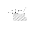
- the protruding portion 135 includes a flat portion 137 and a central-side recessed portion 138.
- the flat portion 137 is formed flat from one end portion 137a on the one end portion 134a side of the horizontal frame body 134 toward the other end portion 137b on the central side in the longitudinal direction of the horizontal frame body 134.
- the center side recess 138 is provided adjacent to the other end 137 b of the flat portion 137.
- the shock-absorbing material 130 is made of thermoplastic elastomer, vulcanized rubber, foamed resin, foamed rubber, or the like, which is rich in elasticity, and has a structure that can be easily molded to cover the capacitor.
- the buffer material 130 is intended to protect the capacitor 10 when testing, packing, and unitizing. For this reason, when unitizing, a capacitor will be accommodated in a housing
- a plurality of capacitor modules 140 are arranged in parallel as shown in FIG. Arranged and stored in the housing 51.
- the side surface portions 140a are arranged adjacent to each other, and the protruding portions 135 and 135 of the cushioning material 130 are formed on the side wall portions 51a and 51c of the housing 51. Adjacent to each other. Then, as shown in FIGS.
- the horizontal plate portion 154 of the L-shaped plate 152 is pressed against the flat portion 137 of the cushioning material 130, and the L-shaped plate is formed by screws 155 and nuts 157.
- the plurality of capacitor modules 140 are fixed in the casing 51 by fixing the vertical plate portion 153 of 152 to the side wall 51 a of the casing 51.
- the size of the corner formed by the vertical plate portion 153 and the horizontal plate portion 154 of the L-shaped plate 152 is ⁇ 11.
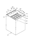
- the casing 51 has a box shape with an open top, and includes four side wall portions 51a, 51b, 51c, 51d and a bottom plate portion (not shown).
- the side wall 51a and the side wall 51c face each other.
- the side wall portions 51b and 51d connect the end portions of the two side wall portions 51a and 51c, and face each other.
- the bottom plate portion is connected to the side wall portions 51a, 51b, 51c, 51d. As a result, the lower side of the casing 51 is closed.
- Patent Document 1 describes an electrochemical storage element module as a technique for housing and fixing a plurality of capacitors in a casing.
- the capacitor module 140 can be fixed to the casing 51 by using the L-shaped plate 152, the screw 155, and the nut 157. However, if the capacitor module 140 is not firmly fixed to the casing 51, the unit is attached to the unit. When vibration is applied, the capacitor may vibrate and have an adverse effect such as damage to the capacitor.
- an electric double layer capacitor has been described as an example of an electrochemical element, but the same problem occurs when a secondary battery such as a lithium ion battery is covered with an aluminum laminate film.
- the present invention has been made to solve the above-described problems, and an object thereof is to provide an electrochemical element unit that can easily fix an electrochemical element to a casing. .
- the electrochemical element unit according to the first invention for solving the above-described problem is: An electrochemical element unit containing a plurality of electrochemical elements connected in parallel or in series in a box-shaped housing,
- the electrochemical element is an electrochemical element module assembled with a protective member that covers the electrochemical element body, By fixing the fixture to the casing, the fixture is pressed against the protective member to fix the electrochemical element module in the casing.
- the electrochemical element unit according to the second invention for solving the above-described problem is An electrochemical element unit according to the first invention,
- the fixture includes a vertical plate portion attached to the housing and a horizontal plate portion connected to the vertical plate portion and fixing the protection member,
- the protective member includes an inclined portion.
- the electrochemical element unit according to the third invention for solving the above-described problem is An electrochemical element unit according to a second invention,
- the inclined portion is formed such that a central portion side in the longitudinal direction of the protective member is above the end portion side of the protective member.
- the electrochemical element unit according to the fourth invention for solving the above-described problem is An electrochemical element unit according to a third invention,
- the corner portion constituted by the vertical plate portion and the horizontal plate portion of the fixture is formed to be smaller than the corner portion on the end portion side of the protection member in the inclined portion.
- the electrochemical element unit according to the fifth invention for solving the above-described problem is An electrochemical element unit according to a second invention,
- the inclined portion is provided in the vicinity of an end portion of the protection member.
- An electrochemical element unit according to a sixth invention for solving the above-described problem is An electrochemical element unit according to a second invention,
- the protective member includes a recess,
- the concave portion is formed adjacent to an end portion side of the protection member in the inclined portion.
- the electrochemical element unit according to the seventh invention for solving the above-mentioned problem is An electrochemical element unit according to the first invention,
- the electrochemical element is an electric double layer capacitor or a lithium ion battery covered with an aluminum laminate film.
- the electrochemical element unit according to the present invention is an electrochemical element unit in which a plurality of electrochemical elements connected in parallel or in series are housed in a box-shaped housing, wherein the electrochemical element is an electric element.
- An electrochemical element module in which a protective member that covers the chemical element body is assembled, and by fixing a fixture to the casing, the fixture is pressed against the protective member, and the electrochemical element module is placed in the casing. By making it fix, an electrochemical element module can be easily fixed to a housing
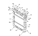
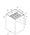
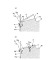
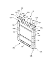
- FIG. 1 is a perspective view of an electric double layer capacitor module according to an embodiment of the present invention. It is the figure which showed typically the cross section of the edge part in the upper horizontal frame body of the buffer material of an electric double layer capacitor. It is a perspective view of the electric double layer capacitor unit concerning one embodiment of the present invention. It is a figure for demonstrating the attachment operation
- the electrochemical element unit according to the present embodiment includes a plurality of electrochemical elements connected in parallel or in series in a box-shaped housing.
- the electrochemical element body is applied to an electric double layer capacitor.
- the electric double layer capacitor 10 is capable of transmitting ions and has a plate-like separator 11 and plate-like activated carbon electrodes 12 and 13 disposed on both side surfaces of the separator 11. And the cell 14 is configured.
- the electric double layer capacitor 10 has a rectangular parallelepiped shape in which cells 14 having a required voltage (three in the illustrated example) are stacked and current collectors 15 are arranged between adjacent cells 13.
- the collector electrodes 16 and 17 are disposed outside the three cells 14 stacked.
- packing 20 for sealing is pinched
- the packing 20 also serves as insulation between the stacked layers.
- end plates 18 and 19 are respectively arranged on both sides of the collector electrodes 16 and 17, the fastening screws 22 are passed through the screw holes of the end plates 18 and 19, and both female threads are processed between the end plates 18 and 19.
- a large applied pressure is obtained by inserting the insulating spacer 21 and tightening the insulating spacer 21 from both sides with the tightening screw 22.
- the capacitor 10 has a flat rectangular shape.
- the outer periphery of the capacitor 10 having the above-described configuration is covered with an aluminum laminate film 23, and the inside of the aluminum laminate film 23 and the inside of the capacitor 10 are decompressed, welded in a vacuum state, and completely covered and sealed.
- a pair of cushioning materials (protective members) 30 and 30 are assembled so as to cover the outer periphery of the capacitor 10 together with the aluminum laminate film 23. ing.
- the buffer material 30 is fixed to the capacitor 10 with, for example, a double-sided tape (not shown).
- the cushioning material 30 is a frame and has a substantially rectangular shape along the corners of the capacitor 10 corresponding to the end plates 18 and 19 (see FIG. 1) so as to particularly protect the corners (edges) of the capacitor 10. Is formed.
- the cushioning material 30 includes first and second vertical frame bodies 31 and 32 and upper and lower horizontal frame bodies 33 and 34.
- the first vertical frame body 31 and the second vertical frame body 32 face each other.
- the lower horizontal frame 33 and the upper horizontal frame 34 are opposed to each other by connecting ends of the first and second vertical frame bodies 31 and 32.
- Protrusions 35 and 35 are provided at the end portions 34a and 34b of the upper horizontal frame 34, respectively.
- a central side recess 38 is formed adjacent to the protrusion 35 on the central side in the longitudinal direction of the upper horizontal frame 34 of the cushioning material 30.
- a substantially central portion in the longitudinal direction of the upper horizontal frame 34 is recessed as compared with its surroundings.
- the projecting portion 35 is formed with an inclined portion 37 and a central-side recessed portion 38.
- the inclined portion 37 is inclined such that the center side of the upper horizontal frame 34 is above the end portions 34a and 34b.
- the inclined portion 37 on the one end portion 34a side of the upper horizontal frame 34 is formed to be inclined from the one end portion 37a toward the other end portion 37b on the central side in the longitudinal direction of the upper horizontal frame body 34. Yes.
- the other end portion 37b is formed to be higher than the one end portion 37a.
- the corner portion ⁇ 1 on the one end portion 37a side of the inclined portion 37 is formed to have an obtuse angle.
- the corner portion ⁇ 1 is formed larger than the corner portion ⁇ 2 formed by the vertical plate portion 53 and the horizontal plate portion 54 of the fixture 52 (see FIGS. 5A and 5B) described later. .
- the inclined portion 37 on the other end 34 b side of the upper horizontal frame 34 is also formed in the same manner as the inclined portion 37 on the one end 34 a of the upper horizontal frame 34.
- the vertical plate portion 53 of the fixture 52 comes into contact with the side wall portions 51 a and 51 c of the casing 51 by the surface, so that the horizontal plate portion 54 of the fixture 52 is pressed against the inclined portion 37 of the cushioning material 30. . Therefore, the capacitor module 40 can be easily fixed to the housing 51.
- An end side recess 36 is formed adjacent to the inclined portion 37 on the end portions 34 a and 34 b side of the upper horizontal frame 34 of the cushioning material 30.
- thermoplastic elastomer for example, thermoplastic elastomer, vulcanized rubber, foamed resin, foamed rubber and the like having high elasticity can be used, but are not necessarily limited thereto.
- the fixture 52 has a substantially L-shaped cross section, and has a vertical plate portion (housing mounting portion) 53 and a horizontal plate portion (buffer material fixing portion) connected to the vertical plate portion 53. 54.
- a screw hole (not shown) is formed in the vertical plate portion 53 of the fixture 52.
- the corner portion ⁇ 2 formed by the vertical plate portion 53 and the horizontal plate portion 54 of the fixture 52 is formed smaller than the corner portion ⁇ 1 (see FIG. 3) on the one end portion 37a side of the inclined portion 37 of the cushioning material 30.
- the width of the fixture 52 is shorter than the size between the side wall 51b and the side wall 51d of the casing 51 (see FIG. 4).
- the length of the vertical plate portion 53 is shorter than that of the horizontal plate portion 54.
- Examples of the material of the fixture 52 include steel having high rigidity.
- the length of the vertical plate portion 53 is shorter than the size of the end side recess 36 of the capacitor module 40.
- the length of the horizontal plate portion 54 is approximately the same size as the inclined portion 37 of the capacitor module 40.
- a screw hole (not shown) is provided at a location facing the end side recess 36 of the capacitor module 40. ) Is formed.
- the screw hole is a long hole having a long diameter in the vertical direction in FIGS. 4, 5 (a), and 5 (b). Therefore, the fixing tool 52 can be fixed to the side wall portions 51 a and 51 c of the housing 51 by the seated screws 55.
- a plurality (four in the illustrated example) of capacitor modules 40 are accommodated in the casing 51.
- the plurality of capacitor modules 40 are disposed such that the side surface portions 40a are adjacent to each other, and the protruding portion 35 of the cushioning material 30 is disposed upward.
- the end portions 34 a and 34 b of the upper horizontal frame 34 of the cushioning material 30 are disposed adjacent to the side wall portions 51 a and 51 c of the housing 51.
- the inclined portion 37 and the end-side recessed portion 36 of the cushioning material 30 are arranged to face the side wall portions 51 a and 51 c of the housing 51.
- the fixture 52 is arranged in the casing 51, and the vertical plate portion 53 of the fixture 52 is arranged in the end side recess 36 of the cushioning material 30.
- a seated screw 55 is attached from the outside of the housing 51 to the vertical plate portion 53 of the fixing device 52 disposed in the housing 51, and the fixing tool 52 is fixed by the seated screw 55.
- the vertical plate portion 53 is temporarily fixed in the housing 51.
- a part of the seating surface of the seated screw 55 and the side wall 51 a of the housing 51 come into contact with each other.
- the seated screw 55 is tightened.
- a contact portion between a part of the seat surface of the seated screw 55 and the side wall portion of the housing serves as a fulcrum, and the escape hole is lost due to the screw hole of the seated screw 55 and the side wall portion 51a.
- 53 moves so as to come into surface contact with the side wall portion 51a of the casing 51, while the horizontal plate portion 54 of the fixture 52 moves in the direction of arrow A.
- the cushioning material 30 is not limited to the force (downward force) applied to the bottom plate portion (not shown) of the casing 51 by the fixture 52, but the longitudinal center of the upper horizontal frame 34 of the cushioning material 30. It is also fixed by force to the side (lateral force). Accordingly, the capacitor module 40 can be easily fixed in the casing 51 without the operator pressing the fixing tool 52 directly into the buffer material 30 or pressing the fixing tool 52 into the buffer material 30 with a jig or the like. Can do.
- the fixing tool 52 when fixing the fixing tool 52 to the side wall 51c side of the casing 51, the same operation as that for fixing the fixing tool 52 to the side wall 51a of the casing 51 is performed.
- the fixing tool 52 can be attached to 51c.
- the box-shaped housing 51 is an electrochemical element unit that houses a plurality of electrochemical elements connected in parallel or in series
- the electrochemical element is a capacitor module 40 in which the buffer materials 30 and 30 that cover the capacitor 10 are assembled.
- the capacitor 10 is used as the electrochemical element body.
- the present invention can be applied to a lithium ion battery, and even in such a case, the same operational effects as described above can be obtained.
- the frame-shaped cushioning material 30 that covers at least the edge of the capacitor 10 is shown as an example of the protective member, but a storage case that houses the capacitor as the protective member, a flat cushioning material that covers the side surface of the capacitor, and the like. Even in such a case, the same effects as described above can be obtained.
- the electrochemical element unit in which the four capacitor modules 40 are accommodated in the casing 51 is shown as an example.
- the invention is applied to an electrochemical element unit in which three or less or five or more capacitor modules are accommodated in the casing. Even in such a case, the same effects as described above can be obtained.
- the fixing tool 52 is fixed to the casing 51 with the seated screw 55.
- the fixing tool 52 can be fixed to the casing 51 with a flanged screw, a screw, a flat washer, or the like. is there.
- the present invention can be used for electrochemical element units such as electric double layer capacitor units and lithium ion battery units.
Landscapes
- Engineering & Computer Science (AREA)
- Power Engineering (AREA)
- Microelectronics & Electronic Packaging (AREA)
- Electric Double-Layer Capacitors Or The Like (AREA)
- Battery Mounting, Suspending (AREA)
- Sealing Battery Cases Or Jackets (AREA)
Abstract
電気化学素子を筐体に容易に固定することができる電気化学素子ユニットを提供することにある。そこで、箱型の筐体51内に、並列または直列に接続される複数の電気化学素子を収納してなる電気化学素子ユニットであって、前記電気化学素子が電気二重層キャパシタ10を覆う緩衝材30,30を組み付けたキャパシタモジュール40であり、筐体51に固定具52を固定することにより、固定具52が緩衝材30に押し付けられて当該筐体51内にキャパシタモジュール40を固定するようにした。
Description
本発明は、電気二重層キャパシタユニットまたはリチウムイオン電池ユニットなどの電気化学素子ユニットに関する。
電気二重層キャパシタは、分極性電極に電解質中のアニオン、カチオンを正極、負極表面に物理吸着させて電気を蓄えることを原理としている。
バイポーラ型電気二重層キャパシタ(以後、キャパシタと呼称する)は、平板状の活性炭電極、集電極を積層し、これらの間にイオンが通過可能なセパレータを挟んだ積層型である。活性炭電極、集電極の外周部には内部の電解質が漏れ出さないように、シールを行うためパッキンを挟んでいる。このパッキンは同時に積層間での絶縁も兼ねている。
キャパシタの組立てを行う際には、必要な耐電圧分のセル(対向する活性炭電極間に挟まれる電解質の最小単位)をパッキンと交互に積み重ね(単セル耐電圧2.5V程度)、終端にエンドプレートで締付けることにより、密閉構造を保っている。
セル間で完全なシールを行うには、エンドプレート間に十分な締め付け力を与える必要があるため、両側のエンドプレートのねじ穴から金属ねじを通し、エンドプレート間には、両雌ねじ加工を行ったスペーサを入れ両側からねじで締め付けることにより大きな加圧力を得ている。
さらに、水分進入を防止してキャパシタ内部の電解液に水分を混入させないようにするため、キャパシタの外周をアルミラミネートフィルムで覆い、アルミラミネートフィルムの内部およびキャパシタ内部を減圧し、真空状態として溶着し、完全に覆い密封することにより外装している。これにより、特性劣化、ガス発生を抑えている。
このアルミラミネートフィルムは、金属アルミ箔をポリプロピレンおよびポリエチレンなどでラミネートしたフィルムであるため、机などにぶつけるなど、外的に衝撃が加わると簡単に穴が開いてしまい、空気中の水分進入が起こり、特性の低下を起こす。
そこで、このような外的衝撃からアルミラミネートフィルムを保護するものとして、図6に示すように、キャパシタ10の外周(特に角)をアルミラミネートフィルム23ごと覆うように1組の緩衝材130,130を設けたものがある。緩衝材130は枠体であって略長方形状に形成されている。緩衝材130は、2つの縦枠体131,132と2つの横枠体133,134とを有する。2つの縦枠体131,132は対向している。2つの横枠体133,134は、2つの縦枠体131,132の端部同士を連結するものであって、対向している。横枠体134の端部134a,134b近傍に突出部135,135がそれぞれ設けられている。
突出部135は、図6および図7に示すように、平坦部137と、中央部側凹み部138とを備える。平坦部137は、横枠体134の一方の端部134a側の一方の端部137aから横枠体134の長手方向中央部側の他方の端部137bに向けて平坦に形成されている。中央部側凹み部138は、平坦部137の他方の端部137bに隣接して設けられている。
緩衝材130には弾力性に富んだ熱可塑性エラストマ、加硫ゴム、発泡樹脂、発泡ゴム等を用い、成型して容易にキャパシタを覆える構造となっている。
この緩衝材130は、試験、梱包、ユニット化する際にキャパシタ10を保護することを目的としている。このため、ユニット化する場合キャパシタを緩衝材ごと筐体に収容して固定することとなる。
上述したように1組の緩衝材130,130がキャパシタ10に組み付けられたキャパシタモジュール140をユニット化する場合、図8に示すように、複数のキャパシタモジュール140(図示例では4つ)が並列に配置されて筐体51内に収納される。具体的には、複数のキャパシタモジュール140は、側面部140a(図6参照)同士が隣接して配置されると共に、緩衝材130の突出部135,135が筐体51の側壁部51a,51cに隣接して配置される。そして、図8、図9(a)および図9(b)に示すように、緩衝材130の平坦部137にL字板152の横板部154を押し当てビス155およびナット157によりL字板152の縦板部153を筐体51の側壁部51aに固定することにより、複数のキャパシタモジュール140を筐体51内に固定している。L字板152の縦板部153と横板部154とで構成される角部の大きさはθ11となっている。
筐体51は、上方が開放した箱型であって、4つの側壁部51a,51b,51c,51dと図示しない底板部とで構成されている。側壁部51aと側壁部51cとが対向している。側壁部51b,51dは、2つの側壁部51a,51cの端部同士を連結するものであって、対向している。前記底板部は、側壁部51a,51b,51c,51dと接続している。これにより、筐体51の下方側が閉塞されている。
複数のキャパシタを筐体に収納して固定する技術として、例えば特許文献1には電気化学蓄電素子モジュールが記載されている。
上述したようにL字板152およびビス155ならびにナット157を用いてキャパシタモジュール140を筐体51に固定することができるものの、筐体51へのキャパシタモジュール140の固定をしっかり行わなければ、ユニットに振動が加わった際、キャパシタが振動して当該キャパシタに損傷など、悪影響を及ぼしてしまう可能性がある。
そこで、ユニットの形状にもよるが、緩衝材130(図6参照)の反発力が大きいため、ユニットを組立てる際、図9(a)および図9(b)に示すように、力F11でL字板152の横板部154を緩衝材130の平坦部137に向けて押圧するため、かなりの力を必要とし、一人で組み立て作業を行うのは極めて困難となったり、場合によっては何らかの治具が必要となったりするなど、作業性が非常に悪い。
ここでは、電気化学素子として電気二重層キャパシタを例にして説明したが、リチウムイオン電池などの二次電池をアルミラミネートフィルムで覆う場合には同様な問題を生じる。
以上のことから、本発明は前述した課題を解決するために為されたものであって、電気化学素子を筐体に容易に固定することができる電気化学素子ユニットを提供することを目的とする。
前述した課題を解決する第1の発明に係る電気化学素子ユニットは、
箱型の筐体内に、並列または直列に接続される複数の電気化学素子を収納してなる電気化学素子ユニットであって、
前記電気化学素子が電気化学素子本体を覆う保護部材を組み付けた電気化学素子モジュールであり、
前記筐体に固定具を固定することにより、当該固定具が前記保護部材に押し付けられて当該筐体内に前記電気化学素子モジュールを固定するようにした
ことを特徴とする。
箱型の筐体内に、並列または直列に接続される複数の電気化学素子を収納してなる電気化学素子ユニットであって、
前記電気化学素子が電気化学素子本体を覆う保護部材を組み付けた電気化学素子モジュールであり、
前記筐体に固定具を固定することにより、当該固定具が前記保護部材に押し付けられて当該筐体内に前記電気化学素子モジュールを固定するようにした
ことを特徴とする。
前述した課題を解決する第2の発明に係る電気化学素子ユニットは、
第1の発明に係る電気化学素子ユニットであって、
前記固定具は前記筐体に取付けられる縦板部と前記縦板部に接続し前記保護部材を固定する横板部とを備え、
前記保護部材は傾斜部を備える
ことを特徴とする。
第1の発明に係る電気化学素子ユニットであって、
前記固定具は前記筐体に取付けられる縦板部と前記縦板部に接続し前記保護部材を固定する横板部とを備え、
前記保護部材は傾斜部を備える
ことを特徴とする。
前述した課題を解決する第3の発明に係る電気化学素子ユニットは、
第2の発明に係る電気化学素子ユニットであって、
前記傾斜部は、前記保護部材の端部側よりも前記保護部材の長手方向中央部側が上方となるように形成される
ことを特徴とする。
第2の発明に係る電気化学素子ユニットであって、
前記傾斜部は、前記保護部材の端部側よりも前記保護部材の長手方向中央部側が上方となるように形成される
ことを特徴とする。
前述した課題を解決する第4の発明に係る電気化学素子ユニットは、
第3の発明に係る電気化学素子ユニットであって、
前記固定具の前記縦板部と前記横板部で構成される角部は、前記傾斜部における前記保護部材の端部側の角部よりも小さく形成されている
ことを特徴とする。
第3の発明に係る電気化学素子ユニットであって、
前記固定具の前記縦板部と前記横板部で構成される角部は、前記傾斜部における前記保護部材の端部側の角部よりも小さく形成されている
ことを特徴とする。
前述した課題を解決する第5の発明に係る電気化学素子ユニットは、
第2の発明に係る電気化学素子ユニットであって、
前記傾斜部が前記保護部材の端部近傍に設けられる
ことを特徴とする。
第2の発明に係る電気化学素子ユニットであって、
前記傾斜部が前記保護部材の端部近傍に設けられる
ことを特徴とする。
前述した課題を解決する第6の発明に係る電気化学素子ユニットは、
第2の発明に係る電気化学素子ユニットであって、
前記保護部材は凹み部を備え、
前記凹み部は、前記傾斜部における当該保護部材の端部側に隣接して形成される
ことを特徴とする。
第2の発明に係る電気化学素子ユニットであって、
前記保護部材は凹み部を備え、
前記凹み部は、前記傾斜部における当該保護部材の端部側に隣接して形成される
ことを特徴とする。
前述した課題を解決する第7の発明に係る電気化学素子ユニットは、
第1の発明に係る電気化学素子ユニットであって、
前記電気化学素子が、アルミラミネートフィルムによって外装された電気二重層キャパシタ、またはリチウムイオン電池である
ことを特徴とする。
第1の発明に係る電気化学素子ユニットであって、
前記電気化学素子が、アルミラミネートフィルムによって外装された電気二重層キャパシタ、またはリチウムイオン電池である
ことを特徴とする。
本発明に係る電気化学素子ユニットによれば、箱型の筐体内に、並列または直列に接続される複数の電気化学素子を収納してなる電気化学素子ユニットであって、前記電気化学素子が電気化学素子本体を覆う保護部材を組み付けた電気化学素子モジュールであり、前記筐体に固定具を固定することにより、当該固定具が前記保護部材に押し付けられて当該筐体内に前記電気化学素子モジュールを固定するようにしたことで、電気化学素子モジュールを筐体に容易に固定することができる。これにより、作業性が向上する。
本発明の一実施形態に係る電気化学素子ユニットについて、図1~図5を参照して具体的に説明する。
本実施形態に係る電気化学素子ユニットは、箱型の筐体内に、並列または直列に接続される複数の電気化学素子を収納してなるものである。
本実施形態では、電気化学素子本体として電気二重層キャパシタに適用したものである。
本実施形態では、電気化学素子本体として電気二重層キャパシタに適用したものである。
本実施形態に係る電気二重層キャパシタ10は、図1に示すように、イオンが透過可能であり平板状のセパレータ11と、このセパレータ11の両側面に配置された平板状の活性炭電極12,13とで構成されるセル14を有する。この電気二重層キャパシタ10は、必要な電圧分(図示例では三つ)のセル14を積層し、隣接するセル13間には集電体15を配置した直方体状のものである。
上述したように3つのセル14を積層したものの外側に集電極16,17が配置されている。そして、活性炭電極12,13および集電極16,17の外周部には内部の電解質が漏れ出さないように、シールを行うためのパッキン20を挟んでいる。このパッキン20は同時に積層間での絶縁も兼ねている。
また、集電極16,17の両側にはエンドプレート18,19をそれぞれ配置し、エンドプレート18,19のねじ穴から締め付けねじ22を通し、エンドプレート18,19間には両雌ねじ加工を行った絶縁スペーサ21を入れ、両側から締め付けねじ22で絶縁スペーサ21を締め付けることにより大きな加圧力を得ている。これにより、キャパシタ10は扁平の角型形状となっている。
さらに、上述した構成のキャパシタ10の外周をアルミラミネートフィルム23で覆い、アルミラミネートフィルム23の内部およびキャパシタ10内部を減圧し、真空状態として溶着し、完全に覆い密封することにより外装している。
本実施形態では、外的衝撃からキャパシタ10を保護するため、図2に示すように、キャパシタ10の外周をアルミラミネートフィルム23ごと覆うように1組の緩衝材(保護部材)30,30を組み付けている。緩衝材30は、例えば、両面テープ(図示省略)でキャパシタ10に固定されている。
緩衝材30は、枠体であって、キャパシタ10の角部(縁部)を特に保護するように、エンドプレート18,19(図1参照)に対応するキャパシタ10の角部に沿う略長方形状に形成されている。緩衝材30は、第一,第二の縦枠体31,32と上下の横枠体33,34とを有する。第一の縦枠体31と第二の縦枠体32は対向している。下横枠体33と上横枠体34は、第一,第二の縦枠体31,32の端部同士を連結し、対向している。上横枠体34の端部34a,34bに突出部35,35がそれぞれ設けられている。緩衝材30の上横枠体34の長手方向中央部側には、突出部35に隣接して中央部側凹み部38が形成されている。言い換えると、上横枠体34の長手方向略中央部分がその周りと比べて凹んでいる。これにより、キャパシタ10に1組の緩衝材30,30を組み付けてキャパシタモジュール40としても、キャパシタ10の端子部24,25が緩衝材30の上横枠体34における長手方向略中央部にて露出するため、複数のキャパシタ10を直列または並列に容易に接続することができる。
突出部35には、図2および図3に示すように、傾斜部37と中央部側凹み部38とが形成されている。傾斜部37は、上横枠体34の中央部側が端部34a,34b側よりも上方となるように傾斜している。上横枠体34の一方の端部34a側の傾斜部37は、一方の端部37aから上横枠体34の長手方向中央部側の他方の端部37bに向けて傾斜して形成されている。他方の端部37bが、一方の端部37aと比べて上方となるように形成されている。具体的には、傾斜部37の一方の端部37a側の角部θ1が鈍角となるように形成されている。この角部θ1は、後述する固定具52(図5(a)および図5(b)参照)の縦板部53と横板部54とで構成される角部θ2よりも大きく形成されている。上横枠体34の他方の端部34b側の傾斜部37も、上横枠体34の一方の端部側34aの傾斜部37と同様に形成されている。これにより、筐体51内にキャパシタモジュール40を収納した状態で、筐体51の外側から座付きビス55などにより、筐体51内にて、固定具52を筐体51の側壁部51a,51cに固定したときに、固定具52の縦板部53が筐体51の側壁部51a,51cに面で接触することにより、固定具52の横板部54が緩衝材30の傾斜部37に押し付けられる。よって、キャパシタモジュール40を筐体51に容易に固定することができる。
緩衝材30の上横枠体34の端部34a,34b側には、傾斜部37に隣接して端部側凹み部36が形成される。これにより、キャパシタモジュール40を筐体51内に収納した状態で、筐体51内にて、後述する固定具52の縦板部53と筐体51の側壁部51a,51cとを対向して配置することができ、固定具52の取付け作業を容易に行うことができる。
緩衝材30の材質としては、例えば、弾力性に富んだ熱可塑性エラストマ、加硫ゴム、発泡樹脂、発泡ゴムなどを用いることが可能であるが、必ずしもこれらに限定されるものではない。
固定具52は、図5に示すように、断面略L字形状であって、縦板部(筐体取付部)53と、この縦板部53に接続する横板部(緩衝材固定部)54とを備える。固定具52の縦板部53にはビス穴(図示せず)が形成されている。固定具52の縦板部53と横板部54とで構成される角部θ2は、緩衝材30の傾斜部37の一方の端部37a側の角部θ1(図3参照)よりも小さく形成されている。固定具52の幅は筐体51(図4参照)の側壁部51bと側壁部51dの間の大きさよりも短く形成されている。縦板部53の長さは横板部54よりも短く形成されている。固定具52の材質としては、例えば、剛性の高い鋼鉄などが挙げられる。縦板部53の長さは、キャパシタモジュール40の端部側凹み部36の大きさよりも短く形成されている。横板部54の長さは、キャパシタモジュール40の傾斜部37と同程度の大きさで形成されている。
なお、筐体51の側壁部51a,51cにおける、筐体51内に、キャパシタモジュール40を収容した際に、キャパシタモジュール40の端部側凹み部36に対向する箇所には、ビス穴(図示せず)が形成されている。ビス穴は、図4および図5(a)ならびに図5(b)中にて上下方向で長径をなす長穴である。よって、座付きビス55により、筐体51の側壁部51a,51cに固定具52を固定することができる。
なお、筐体51の側壁部51a,51cにおける、筐体51内に、キャパシタモジュール40を収容した際に、キャパシタモジュール40の端部側凹み部36に対向する箇所には、ビス穴(図示せず)が形成されている。ビス穴は、図4および図5(a)ならびに図5(b)中にて上下方向で長径をなす長穴である。よって、座付きビス55により、筐体51の側壁部51a,51cに固定具52を固定することができる。
続いて、上述したキャパシタモジュール40を筐体51内に複数収容し、これらキャパシタモジュール40を固定具52で筐体51に固定したキャパシタユニットを作製する手順について説明する。
まず、筐体51内にキャパシタモジュール40を複数(図示例では、4つ)収容する。複数のキャパシタモジュール40は、側面部40a同士が隣接して配置されると共に、緩衝材30の突出部35が上方に向けて配置される。さらに、緩衝材30の上横枠体34の端部34a,34bが筐体51の側壁部51a,51cに隣接して配置される。言い換えると、緩衝材30の傾斜部37および端部側凹み部36は、筐体51の側壁部51a,51cに対向して配置される。
続いて、筐体51内に固定具52を配置し、固定具52の縦板部53を緩衝材30の端部側凹み部36内に配置する。
続いて、図5(a)に示すように、筐体51内に配置される固定具52の縦板部53に筐体51の外側から座付きビス55を取り付け、座付きビス55により固定具52の縦板部53を筐体51内で仮固定する。このとき、座付きビス55の座面の一部と筐体51の側壁部51aとが接触する。そして、座付きビス55を締め付ける。このとき、座付きビス55の座面の一部と筐体の側壁部との接触部がてこの支点となり、座付きビス55と側壁部51aのビス穴により逃げ場を失い、固定具52の縦板部53が筐体51の側壁部51aと面接触するように移動していく一方、固定具52の横板部54が矢印Aの方向へ移動していく。
そして、図5(b)に示すように、座付きビス55を完全に締め付けることにより、固定具52の縦板部53と横板部54の角部θ2が緩衝材30の傾斜部37の一方の端部側の角部θ1よりも小さいため、固定具52の横板部54が緩衝材30の傾斜部37に押し付けられる。すなわち、固定具52の横板部54により緩衝材30の傾斜部37に対して力F1が作用する。このときの力F1は、上述したように傾斜部37の他方の端部37bが一方の端部37aよりも上方にあるため、緩衝材30の上横枠体34の長手方向中央部側へ作用する力F1(x)と、緩衝材30の下方向へ作用する力F1(y)とで構成される。すなわち、緩衝材30は、固定具52により、筐体51の底板部(図示せず)への力(下方向の力)のみではなく、当該緩衝材30の上横枠体34の長手方向中央部側への力(横方向の力)でも固定される。これにより、作業者が固定具52を緩衝材30に直接押し込んだり、治具などにより固定具52を緩衝材30に押し込んだりしなくてもキャパシタモジュール40を筐体51内に容易に固定することができる。
また、筐体51の側壁部51c側に固定具52を固定する場合も、筐体51の側壁部51aに固定具52を固定する作業と同様な作業を行うことにより、筐体51の側壁部51cに固定具52を取り付けることができる。
したがって、本実施形態に係る電気化学素子ユニットによれば、箱型の筐体51内に、並列または直列に接続される複数の電気化学素子を収納してなる電気化学素子ユニットであって、前記電気化学素子がキャパシタ10を覆う緩衝材30,30を組み付けたキャパシタモジュール40であり、筐体51に固定具52を固定することにより、固定具52が緩衝材30に押し付けられて当該筐体51内にキャパシタモジュール40を固定するようにしたため、キャパシタモジュール40を筐体51内に容易に固定することができる。
なお、上記では、電気化学素子本体としてキャパシタ10を用いて説明したが、リチウムイオン電池に適用することも可能であり、このような場合であっても上記と同様な作用効果を奏する。
上記では、保護部材としてキャパシタ10の少なくとも縁部を覆う枠体状の緩衝材30を例に示したが、保護部材としてキャパシタを収納する収納ケースやキャパシタの側面部を覆う平板状の緩衝材などに適用することも可能であり、このような場合であっても上記と同様な作用効果を奏する。
上記では、4つのキャパシタモジュール40を筐体51内に収納した電気化学素子ユニットを例に示したが、3つ以下または5つ以上のキャパシタモジュールを筐体内に収納する電気化学素子ユニットに適用することも可能であり、このような場合であっても上記と同様な作用効果を奏する。
上記では、座付きビス55により固定具52を筐体51に固定したが、座付きビス55の代わりに、フランジ付きビス、ビス及び平座金などにより固定具52を筐体51に固定することも可能である。
本発明は、電気二重層キャパシタユニットやリチウムイオン電池ユニットなどの電気化学素子ユニットに利用することができる。
10 電気二重層キャパシタ
11 セパレータ
12,13 活性炭電極
14 セル
15 集電体
16,17 集電極(集電端子)
18,19 エンドプレート
20 パッキン
21 スペーサ
22 ねじ
23 アルミラミネートフィルム
24,25 端子部
30 緩衝材(保護部材)
35 突出部
36 端部側凹み部
37 傾斜部
38 中央部側凹み部
40 キャパシタモジュール
51 筐体
52 固定具
53 縦板部
54 横板部
55 座付きビス
11 セパレータ
12,13 活性炭電極
14 セル
15 集電体
16,17 集電極(集電端子)
18,19 エンドプレート
20 パッキン
21 スペーサ
22 ねじ
23 アルミラミネートフィルム
24,25 端子部
30 緩衝材(保護部材)
35 突出部
36 端部側凹み部
37 傾斜部
38 中央部側凹み部
40 キャパシタモジュール
51 筐体
52 固定具
53 縦板部
54 横板部
55 座付きビス
Claims (7)
- 箱型の筐体内に、並列または直列に接続される複数の電気化学素子を収納してなる電気化学素子ユニットであって、
前記電気化学素子が電気化学素子本体を覆う保護部材を組み付けた電気化学素子モジュールであり、
前記筐体に固定具を固定することにより、当該固定具が前記保護部材に押し付けられて当該筐体内に前記電気化学素子モジュールを固定するようにした
ことを特徴とする電気化学素子ユニット。 - 請求項1に記載の電気化学素子ユニットであって、
前記固定具は前記筐体に取付けられる縦板部と前記縦板部に接続し前記保護部材を固定する横板部とを備え、
前記保護部材は傾斜部を備える
ことを特徴とする電気化学素子ユニット。 - 請求項2に記載の電気化学素子ユニットであって、
前記傾斜部は、前記保護部材の端部側よりも前記保護部材の長手方向中央部側が上方となるように形成される
ことを特徴とする電気化学素子ユニット。 - 請求項3に記載の電気化学素子ユニットであって、
前記固定具の前記縦板部と前記横板部で構成される角部は、前記傾斜部における前記保護部材の端部側の角部よりも小さく形成されている
ことを特徴とする電気化学素子ユニット。 - 請求項2に記載の電気化学素子ユニットであって、
前記傾斜部が前記保護部材の端部近傍に設けられる
ことを特徴とする電気化学素子ユニット。 - 請求項2に記載の電気化学素子ユニットであって、
前記保護部材は凹み部を備え、
前記凹み部は、前記傾斜部における当該保護部材の端部側に隣接して形成される
ことを特徴とする電気化学素子ユニット。 - 請求項1に記載の電気化学素子ユニットであって、
前記電気化学素子が、アルミラミネートフィルムによって外装された電気二重層キャパシタ、またはリチウムイオン電池である
ことを特徴とする電気化学素子ユニット。
Applications Claiming Priority (2)
| Application Number | Priority Date | Filing Date | Title |
|---|---|---|---|
| JP2010086683A JP2011222573A (ja) | 2010-04-05 | 2010-04-05 | 電気化学素子ユニット |
| JP2010-086683 | 2010-04-05 |
Publications (1)
| Publication Number | Publication Date |
|---|---|
| WO2011125531A1 true WO2011125531A1 (ja) | 2011-10-13 |
Family
ID=44762485
Family Applications (1)
| Application Number | Title | Priority Date | Filing Date |
|---|---|---|---|
| PCT/JP2011/057277 Ceased WO2011125531A1 (ja) | 2010-04-05 | 2011-03-25 | 電気化学素子ユニット |
Country Status (2)
| Country | Link |
|---|---|
| JP (1) | JP2011222573A (ja) |
| WO (1) | WO2011125531A1 (ja) |
Families Citing this family (3)
| Publication number | Priority date | Publication date | Assignee | Title |
|---|---|---|---|---|
| JP6481200B2 (ja) * | 2015-03-30 | 2019-03-13 | 株式会社明電舎 | 電気二重層キャパシタのユニット構造 |
| JP6977554B2 (ja) * | 2017-12-28 | 2021-12-08 | トヨタ自動車株式会社 | 全固体電池 |
| KR102870579B1 (ko) * | 2021-10-26 | 2025-10-15 | 주식회사 엘지에너지솔루션 | 배터리 팩 |
Citations (2)
| Publication number | Priority date | Publication date | Assignee | Title |
|---|---|---|---|---|
| JPS6438761U (ja) * | 1987-09-02 | 1989-03-08 | ||
| WO2006059421A1 (ja) * | 2004-11-30 | 2006-06-08 | Nec Corporation | 電気デバイス集合体 |
-
2010
- 2010-04-05 JP JP2010086683A patent/JP2011222573A/ja not_active Withdrawn
-
2011
- 2011-03-25 WO PCT/JP2011/057277 patent/WO2011125531A1/ja not_active Ceased
Patent Citations (2)
| Publication number | Priority date | Publication date | Assignee | Title |
|---|---|---|---|---|
| JPS6438761U (ja) * | 1987-09-02 | 1989-03-08 | ||
| WO2006059421A1 (ja) * | 2004-11-30 | 2006-06-08 | Nec Corporation | 電気デバイス集合体 |
Also Published As
| Publication number | Publication date |
|---|---|
| JP2011222573A (ja) | 2011-11-04 |
Similar Documents
| Publication | Publication Date | Title |
|---|---|---|
| JP5208548B2 (ja) | バッテリパック、バッテリパックの梱包方法および組立て方法 | |
| JP5067171B2 (ja) | 電気化学蓄電素子モジュール | |
| JP6205808B2 (ja) | 蓄電素子モジュール | |
| KR101209935B1 (ko) | 배터리팩 고정장치 | |
| JP5597740B2 (ja) | 電池モジュール | |
| JP2017069004A (ja) | 蓄電装置及び蓄電装置の製造方法 | |
| JP2016213104A (ja) | 電池パック | |
| JP2014203745A (ja) | 蓄電装置 | |
| WO2016013150A1 (ja) | 電池モジュール | |
| JP2008186750A (ja) | 緩衝材 | |
| US20180375071A1 (en) | Cell module | |
| WO2011125531A1 (ja) | 電気化学素子ユニット | |
| JP5040611B2 (ja) | 電気化学素子のプロテクタ | |
| US10411231B2 (en) | Energy storage apparatus | |
| JP4934973B2 (ja) | 組電池 | |
| JP2017188375A (ja) | 電池パック | |
| JP6786962B2 (ja) | 電池パックの端子取付構造 | |
| JP4787509B2 (ja) | 電気デバイス集合体 | |
| CN111129563A (zh) | 燃料电池的电池组外壳以及外部约束部件 | |
| JP7110626B2 (ja) | 電気機器 | |
| JP6064878B2 (ja) | 蓄電モジュール | |
| JP2006190611A (ja) | 電源装置 | |
| JP6829597B2 (ja) | 電池モジュール | |
| WO2026070519A1 (ja) | 蓄電モジュール | |
| WO2026094444A1 (ja) | 蓄電モジュール |
Legal Events
| Date | Code | Title | Description |
|---|---|---|---|
| 121 | Ep: the epo has been informed by wipo that ep was designated in this application |
Ref document number: 11765432 Country of ref document: EP Kind code of ref document: A1 |
|
| NENP | Non-entry into the national phase |
Ref country code: DE |
|
| 122 | Ep: pct application non-entry in european phase |
Ref document number: 11765432 Country of ref document: EP Kind code of ref document: A1 |