WO2011125384A1 - 制御装置 - Google Patents
制御装置 Download PDFInfo
- Publication number
- WO2011125384A1 WO2011125384A1 PCT/JP2011/054335 JP2011054335W WO2011125384A1 WO 2011125384 A1 WO2011125384 A1 WO 2011125384A1 JP 2011054335 W JP2011054335 W JP 2011054335W WO 2011125384 A1 WO2011125384 A1 WO 2011125384A1
- Authority
- WO
- WIPO (PCT)
- Prior art keywords
- hydraulic pressure
- torque
- control
- shift
- engagement
- Prior art date
- Legal status (The legal status is an assumption and is not a legal conclusion. Google has not performed a legal analysis and makes no representation as to the accuracy of the status listed.)
- Ceased
Links
Images







Classifications
-
- F—MECHANICAL ENGINEERING; LIGHTING; HEATING; WEAPONS; BLASTING
- F16—ENGINEERING ELEMENTS AND UNITS; GENERAL MEASURES FOR PRODUCING AND MAINTAINING EFFECTIVE FUNCTIONING OF MACHINES OR INSTALLATIONS; THERMAL INSULATION IN GENERAL
- F16H—GEARING
- F16H61/00—Control functions within control units of change-speed- or reversing-gearings for conveying rotary motion ; Control of exclusively fluid gearing, friction gearing, gearings with endless flexible members or other particular types of gearing
- F16H61/04—Smoothing ratio shift
- F16H61/06—Smoothing ratio shift by controlling rate of change of fluid pressure
- F16H61/061—Smoothing ratio shift by controlling rate of change of fluid pressure using electric control means
-
- B—PERFORMING OPERATIONS; TRANSPORTING
- B60—VEHICLES IN GENERAL
- B60K—ARRANGEMENT OR MOUNTING OF PROPULSION UNITS OR OF TRANSMISSIONS IN VEHICLES; ARRANGEMENT OR MOUNTING OF PLURAL DIVERSE PRIME-MOVERS IN VEHICLES; AUXILIARY DRIVES FOR VEHICLES; INSTRUMENTATION OR DASHBOARDS FOR VEHICLES; ARRANGEMENTS IN CONNECTION WITH COOLING, AIR INTAKE, GAS EXHAUST OR FUEL SUPPLY OF PROPULSION UNITS IN VEHICLES
- B60K6/00—Arrangement or mounting of plural diverse prime-movers for mutual or common propulsion, e.g. hybrid propulsion systems comprising electric motors and internal combustion engines
- B60K6/20—Arrangement or mounting of plural diverse prime-movers for mutual or common propulsion, e.g. hybrid propulsion systems comprising electric motors and internal combustion engines the prime-movers consisting of electric motors and internal combustion engines, e.g. HEVs
- B60K6/42—Arrangement or mounting of plural diverse prime-movers for mutual or common propulsion, e.g. hybrid propulsion systems comprising electric motors and internal combustion engines the prime-movers consisting of electric motors and internal combustion engines, e.g. HEVs characterised by the architecture of the hybrid electric vehicle
- B60K6/48—Parallel type
-
- B—PERFORMING OPERATIONS; TRANSPORTING
- B60—VEHICLES IN GENERAL
- B60W—CONJOINT CONTROL OF VEHICLE SUB-UNITS OF DIFFERENT TYPE OR DIFFERENT FUNCTION; CONTROL SYSTEMS SPECIALLY ADAPTED FOR HYBRID VEHICLES; ROAD VEHICLE DRIVE CONTROL SYSTEMS FOR PURPOSES NOT RELATED TO THE CONTROL OF A PARTICULAR SUB-UNIT
- B60W10/00—Conjoint control of vehicle sub-units of different type or different function
- B60W10/04—Conjoint control of vehicle sub-units of different type or different function including control of propulsion units
- B60W10/08—Conjoint control of vehicle sub-units of different type or different function including control of propulsion units including control of electric propulsion units, e.g. motors or generators
-
- B—PERFORMING OPERATIONS; TRANSPORTING
- B60—VEHICLES IN GENERAL
- B60W—CONJOINT CONTROL OF VEHICLE SUB-UNITS OF DIFFERENT TYPE OR DIFFERENT FUNCTION; CONTROL SYSTEMS SPECIALLY ADAPTED FOR HYBRID VEHICLES; ROAD VEHICLE DRIVE CONTROL SYSTEMS FOR PURPOSES NOT RELATED TO THE CONTROL OF A PARTICULAR SUB-UNIT
- B60W10/00—Conjoint control of vehicle sub-units of different type or different function
- B60W10/10—Conjoint control of vehicle sub-units of different type or different function including control of change-speed gearings
- B60W10/11—Stepped gearings
- B60W10/115—Stepped gearings with planetary gears
-
- B—PERFORMING OPERATIONS; TRANSPORTING
- B60—VEHICLES IN GENERAL
- B60W—CONJOINT CONTROL OF VEHICLE SUB-UNITS OF DIFFERENT TYPE OR DIFFERENT FUNCTION; CONTROL SYSTEMS SPECIALLY ADAPTED FOR HYBRID VEHICLES; ROAD VEHICLE DRIVE CONTROL SYSTEMS FOR PURPOSES NOT RELATED TO THE CONTROL OF A PARTICULAR SUB-UNIT
- B60W30/00—Purposes of road vehicle drive control systems not related to the control of a particular sub-unit, e.g. of systems using conjoint control of vehicle sub-units
- B60W30/18—Propelling the vehicle
- B60W30/18009—Propelling the vehicle related to particular drive situations
- B60W30/18072—Coasting
-
- B—PERFORMING OPERATIONS; TRANSPORTING
- B60—VEHICLES IN GENERAL
- B60W—CONJOINT CONTROL OF VEHICLE SUB-UNITS OF DIFFERENT TYPE OR DIFFERENT FUNCTION; CONTROL SYSTEMS SPECIALLY ADAPTED FOR HYBRID VEHICLES; ROAD VEHICLE DRIVE CONTROL SYSTEMS FOR PURPOSES NOT RELATED TO THE CONTROL OF A PARTICULAR SUB-UNIT
- B60W30/00—Purposes of road vehicle drive control systems not related to the control of a particular sub-unit, e.g. of systems using conjoint control of vehicle sub-units
- B60W30/18—Propelling the vehicle
- B60W30/19—Improvement of gear change, e.g. by synchronisation or smoothing gear shift
-
- F—MECHANICAL ENGINEERING; LIGHTING; HEATING; WEAPONS; BLASTING
- F16—ENGINEERING ELEMENTS AND UNITS; GENERAL MEASURES FOR PRODUCING AND MAINTAINING EFFECTIVE FUNCTIONING OF MACHINES OR INSTALLATIONS; THERMAL INSULATION IN GENERAL
- F16H—GEARING
- F16H61/00—Control functions within control units of change-speed- or reversing-gearings for conveying rotary motion ; Control of exclusively fluid gearing, friction gearing, gearings with endless flexible members or other particular types of gearing
- F16H61/21—Providing engine brake control
-
- B—PERFORMING OPERATIONS; TRANSPORTING
- B60—VEHICLES IN GENERAL
- B60L—PROPULSION OF ELECTRICALLY-PROPELLED VEHICLES; SUPPLYING ELECTRIC POWER FOR AUXILIARY EQUIPMENT OF ELECTRICALLY-PROPELLED VEHICLES; ELECTRODYNAMIC BRAKE SYSTEMS FOR VEHICLES IN GENERAL; MAGNETIC SUSPENSION OR LEVITATION FOR VEHICLES; MONITORING OPERATING VARIABLES OF ELECTRICALLY-PROPELLED VEHICLES; ELECTRIC SAFETY DEVICES FOR ELECTRICALLY-PROPELLED VEHICLES
- B60L2240/00—Control parameters of input or output; Target parameters
- B60L2240/40—Drive Train control parameters
- B60L2240/48—Drive Train control parameters related to transmissions
- B60L2240/486—Operating parameters
-
- B—PERFORMING OPERATIONS; TRANSPORTING
- B60—VEHICLES IN GENERAL
- B60W—CONJOINT CONTROL OF VEHICLE SUB-UNITS OF DIFFERENT TYPE OR DIFFERENT FUNCTION; CONTROL SYSTEMS SPECIALLY ADAPTED FOR HYBRID VEHICLES; ROAD VEHICLE DRIVE CONTROL SYSTEMS FOR PURPOSES NOT RELATED TO THE CONTROL OF A PARTICULAR SUB-UNIT
- B60W2510/00—Input parameters relating to a particular sub-units
- B60W2510/10—Change speed gearings
- B60W2510/1025—Input torque
-
- B—PERFORMING OPERATIONS; TRANSPORTING
- B60—VEHICLES IN GENERAL
- B60W—CONJOINT CONTROL OF VEHICLE SUB-UNITS OF DIFFERENT TYPE OR DIFFERENT FUNCTION; CONTROL SYSTEMS SPECIALLY ADAPTED FOR HYBRID VEHICLES; ROAD VEHICLE DRIVE CONTROL SYSTEMS FOR PURPOSES NOT RELATED TO THE CONTROL OF A PARTICULAR SUB-UNIT
- B60W2710/00—Output or target parameters relating to a particular sub-units
- B60W2710/10—Change speed gearings
- B60W2710/1022—Input torque
- B60W2710/1027—Input torque change rate
-
- Y—GENERAL TAGGING OF NEW TECHNOLOGICAL DEVELOPMENTS; GENERAL TAGGING OF CROSS-SECTIONAL TECHNOLOGIES SPANNING OVER SEVERAL SECTIONS OF THE IPC; TECHNICAL SUBJECTS COVERED BY FORMER USPC CROSS-REFERENCE ART COLLECTIONS [XRACs] AND DIGESTS
- Y02—TECHNOLOGIES OR APPLICATIONS FOR MITIGATION OR ADAPTATION AGAINST CLIMATE CHANGE
- Y02T—CLIMATE CHANGE MITIGATION TECHNOLOGIES RELATED TO TRANSPORTATION
- Y02T10/00—Road transport of goods or passengers
- Y02T10/60—Other road transportation technologies with climate change mitigation effect
- Y02T10/62—Hybrid vehicles
-
- Y—GENERAL TAGGING OF NEW TECHNOLOGICAL DEVELOPMENTS; GENERAL TAGGING OF CROSS-SECTIONAL TECHNOLOGIES SPANNING OVER SEVERAL SECTIONS OF THE IPC; TECHNICAL SUBJECTS COVERED BY FORMER USPC CROSS-REFERENCE ART COLLECTIONS [XRACs] AND DIGESTS
- Y02—TECHNOLOGIES OR APPLICATIONS FOR MITIGATION OR ADAPTATION AGAINST CLIMATE CHANGE
- Y02T—CLIMATE CHANGE MITIGATION TECHNOLOGIES RELATED TO TRANSPORTATION
- Y02T10/00—Road transport of goods or passengers
- Y02T10/80—Technologies aiming to reduce greenhouse gasses emissions common to all road transportation technologies
- Y02T10/84—Data processing systems or methods, management, administration
-
- Y—GENERAL TAGGING OF NEW TECHNOLOGICAL DEVELOPMENTS; GENERAL TAGGING OF CROSS-SECTIONAL TECHNOLOGIES SPANNING OVER SEVERAL SECTIONS OF THE IPC; TECHNICAL SUBJECTS COVERED BY FORMER USPC CROSS-REFERENCE ART COLLECTIONS [XRACs] AND DIGESTS
- Y10—TECHNICAL SUBJECTS COVERED BY FORMER USPC
- Y10S—TECHNICAL SUBJECTS COVERED BY FORMER USPC CROSS-REFERENCE ART COLLECTIONS [XRACs] AND DIGESTS
- Y10S903/00—Hybrid electric vehicles, HEVS
- Y10S903/902—Prime movers comprising electrical and internal combustion motors
Definitions
- the present invention has an input member drivingly connected to a rotating electrical machine capable of generating regenerative torque based on a deceleration request of an engine and a vehicle, an output member drivingly connected to a wheel, and a plurality of friction engagement elements, A transmission mechanism that switches a plurality of shift speeds by controlling engagement and release of a plurality of friction engagement elements, shifts the rotational speed of the input member at a gear ratio of each shift speed, and outputs to the output member;
- the present invention relates to a control device for controlling a transmission including
- Patent Document 1 discloses a vehicle drive device including a transmission that has a speed change mechanism that changes gears and changes the rotational speed of an input member at a gear ratio of each gear and outputs the same to an output member.
- the device is already known.
- change gear shift is performed.
- the released frictional engagement element is normally fully released relatively quickly in the initial stage of the shifting operation, and the engaged frictional engagement element slips in a half-engaged state. It is made to engage gradually. This naturally applies also when switching to a gear position with a small gear ratio (upshift) is performed in a state where the accelerator opening of the vehicle is equal to or smaller than a predetermined value.
- Patent Document 1 is a friction engagement element on the side that is released when the shift stage is switched during an upshift in which the accelerator opening of the vehicle is below a predetermined value by the control device.
- Release side frictional engagement element control for switching the hydraulic pressure of the hydraulic oil for the release side element to be switched between the release guarantee pressure that is just before the start of engagement of the release side element and the engagement guarantee pressure that is slightly engaged. Configured to run.
- the hydraulic pressure of the hydraulic oil with respect to the release side element is increased and decreased by a predetermined pressure width ( ⁇ P2) across the stroke end pressure of the release side element.
- ⁇ P2 a predetermined pressure width
- switching between the release guarantee pressure and the engagement guarantee pressure is performed.
- the disengagement element repeatedly alternates between the state of slipping in the half-engaged state and the state of complete disengagement when the shift speed is switched.
- a vehicle drive device used in a hybrid vehicle that uses both an engine and a rotating electrical machine as a drive force source for example, a device described in Patent Document 2 below is known.
- an off-up shift may be performed in the transmission.
- a change-over shift is performed, and the release side element is completely released relatively quickly in the initial stage of the shift operation, and the engaged friction engagement element is in the half-engaged state. It is gradually engaged while slipping.
- the rotating electrical machine is configured to be able to generate regenerative torque based on a vehicle deceleration request.
- regenerative braking is performed by a rotating electrical machine.
- the rotational speed of the input member is greatly reduced due to the relatively large negative torque (regenerative torque) output by the rotating electrical machine and changes rapidly.
- the vehicle drive device described in Patent Document 2 is configured to limit the magnitude of the negative torque output by the rotating electrical machine to a certain level or less when the rotating electrical machine performs regeneration. .
- the rotational speed of the input member that is drivingly connected to the rotating electrical machine is rapidly reduced, and the occurrence of a shift shock in the vehicle is suppressed.
- an input member that is drivingly connected to a rotating electrical machine capable of generating regenerative torque based on a deceleration request of an engine and a vehicle according to the present invention
- an output member that is drivingly connected to wheels
- a plurality of shift stages are controlled by controlling engagement and release of the plurality of friction engagement elements, and the rotational speed of the input member is changed at a gear ratio of each shift stage.
- a speed change mechanism that outputs to the output member.
- the characteristic configuration of the control device for controlling the transmission includes a predetermined determination reference time that is derived based on a change in input torque that is input to the input member.
- element From the time when the release side element slips by lowering the release side hydraulic pressure that is the hydraulic pressure of the hydraulic oil to the release side element, after the release side element starts to slip, the rotational speed of the output member is changed to the rotation speed of the output member
- the special speed change control for maintaining the slip state of the disengagement element is executed over the entire speed change process up to the time point when the rotational speed multiplied by the speed ratio is synchronized with the rotational speed of the input member.
- the “slip state” means a half-engaged state between the fully engaged state and the fully released state. More specifically, the engagement members on both sides of the target frictional engagement element are It means a state in which driving force is transmitted between the input side rotating member and the output side rotating member while having a predetermined differential rotational speed. Further, the “rotary electric machine” is used as a concept including a motor (electric motor), a generator (generator), and a motor / generator that performs both functions of the motor and the generator as necessary. “Drive coupling” refers to a state in which two rotating elements are coupled so as to be able to transmit a driving force, and the two rotating elements are coupled so as to rotate integrally, or the two rotation elements.
- Such a transmission member include various members that transmit rotation at the same speed or a variable speed, and include, for example, a shaft, a gear mechanism, a belt, a chain, and the like.
- an engagement element that selectively transmits rotation and driving force such as a friction clutch or a meshing clutch, may be included.
- the rotating electrical machine performs regeneration after the predetermined determination reference time based on the fact that the predicted input torque that is the predicted value of the input torque after the predetermined determination reference time becomes negative. This can be predicted in advance. Then, when switching to a gear stage with a small gear ratio is performed in a negative torque prediction establishment state in which the predicted input torque becomes negative, the release side hydraulic pressure is reduced and the release side element slips over the entire speed change process. By maintaining the above, the state in which a part of the rotational driving force from the output member is transmitted to the input member side via the disengagement side element is maintained throughout the entire speed change process.
- the above characteristic configuration it is possible to achieve both suppression of shift shock and improvement of energy efficiency when switching to a gear stage having a small gear ratio is performed.
- the negative torque prediction by determining that the negative torque prediction is established, it is predicted in advance that the rotating electrical machine may perform regeneration after a predetermined determination reference time, and the release side
- the special speed change control for keeping the element in the slip state can be started relatively early. Therefore, energy efficiency can be maintained higher.
- the input torque change rate that is the time change rate of the input torque is acquired at a predetermined period, and the predicted torque change rate is derived based on the input torque change rate, and the current input torque and the predicted torque change are derived.
- the predicted input torque is preferably derived based on the rate.
- the predicted torque change rate is calculated at a predetermined period, and the latest input torque change rate and the previous predicted torque change rate are added at a predetermined ratio to derive the latest predicted torque change rate, It is preferable that the predicted input torque is derived by adding a value obtained by multiplying the latest predicted torque change rate by the determination reference time and the current input torque.
- the rate can be derived. Therefore, even when the input torque changes while repeating instantaneous fluctuations, the predicted torque change rate can be derived as an index indicating the overall change tendency. Then, by adding the value obtained by multiplying the latest predicted torque change rate thus derived by the determination reference time and the current input torque, the predicted input torque after the determination reference time at the present time is appropriately set in a predetermined cycle. Can be derived.
- a first limit hydraulic pressure that is a value corresponding to the magnitude of the predicted input torque and that is equal to or greater than the stroke end pressure of the piston of the disengagement element when the predicted input torque is negative is set.
- the disengagement side hydraulic pressure be maintained at a level equal to or greater than the first limit hydraulic pressure throughout the speed change process.
- the release side hydraulic pressure when the predicted input torque is negative, the release side hydraulic pressure is reliably maintained at a pressure equal to or higher than the stroke end pressure of the release side element piston, so the slip state of the release side element is appropriately realized. it can. Further, at that time, the release side hydraulic pressure is maintained at a pressure corresponding to the magnitude of the predicted input torque, so that the slip amount of the release side element can be appropriately adjusted according to the magnitude of the predicted input torque.
- the first limited hydraulic pressure is set to a value that increases as the predicted input torque changes in the negative direction.
- the predicted input torque takes a negative value
- the first limit hydraulic pressure is increased to reduce the slip amount, and the rotational drive transmitted from the output member to the input member side via the disengagement side element. Increase the power ratio. Therefore, a large amount of energy regenerated by the rotating electrical machine can be secured.
- the first limit hydraulic pressure is decreased to increase the slip amount, and the ratio of the rotational driving force transmitted from the output member to the input member side via the disengagement side element is decreased. Therefore, it is possible to suppress an excessive rotational driving force from being transmitted from the output member to the input member side via the disengagement side element.
- a second limited hydraulic pressure that is a value corresponding to the accelerator opening and is equal to or higher than a stroke end pressure of the piston of the disengagement side element in the low accelerator opening state is set, and the special shift control Then, it is preferable that the disengagement side hydraulic pressure is maintained to be equal to or larger than the second limit hydraulic pressure throughout the entire speed change process.
- the disengagement hydraulic pressure is maintained at least equal to or higher than the stroke end pressure of the disengagement element piston throughout the entire shifting process. Therefore, the slip state of the disengagement element can be appropriately realized. Therefore, not only can the above-mentioned effects be obtained when the rotating electrical machine actually outputs negative torque, but also when the rotating electrical machine does not actually output negative torque, It can be appropriately provided for the case of outputting a negative torque.
- the rotating electric machine when switching to a gear position with a small gear ratio is performed when the accelerator opening of the vehicle is equal to or smaller than a predetermined value, the rotating electric machine outputs negative torque from the initial stage of the gear shifting process, and the rotating electric machine It is possible to achieve both suppression of shift shock and improvement of energy efficiency both in the case of outputting negative torque from the middle of the shift process without outputting negative torque in the initial stage of the process.
- a target rotational speed change rate is determined, and in the special speed change control, the actual rotational speed change rate of the input member follows the target rotational speed change rate in synchronization with a decrease in the release side hydraulic pressure.
- the engagement side hydraulic pressure which is the hydraulic pressure of the hydraulic oil with respect to the engagement side element serving as the friction engagement element on the side to be combined, is changed.
- the disengagement side element when the disengagement side element is maintained in the slip state throughout the speed change process, depending on the magnitude of the output torque of the rotating electrical machine, the decrease in the rotation speed of the input member becomes slow, and the speed change time is reduced. There is a possibility of becoming longer.
- the reduction of the rotation speed of the input member which tends to be slow, is assisted by the change of the engagement side oil pressure, and the speed change operation is appropriately performed within the target speed change time. Can be terminated.
- a reference hydraulic pressure change amount required to change the rotational speed of the input member at the target rotational speed change rate is determined, and based on the reference hydraulic pressure change amount, the shift speed is changed. It is preferable that the engagement side hydraulic pressure is changed in accordance with the degree of progress of the process and the output torque of the rotating electrical machine.
- the engagement side hydraulic pressure can be appropriately changed according to the progress of the speed change process and the output torque of the rotating electrical machine. Further, by changing the engagement side hydraulic pressure further based on the reference hydraulic pressure change amount, the rotational speed of the input member can be changed at the target rotational speed change rate, and the speed change operation can be appropriately terminated within the target speed change time. it can.
- a predetermined change coefficient set in advance according to the progress of the shift process and the output torque of the rotating electrical machine The engagement side hydraulic pressure is changed based on a reference hydraulic pressure change amount, and the change coefficient is determined according to the speed change process in at least the first stage among a plurality of stages set according to the progress of the speed change process. It increases as it progresses, and at least at the final stage, it decreases as the shift process progresses.
- the output torque of the rotating electrical machine is negative, it increases as the output torque of the rotating electrical machine changes in the positive direction.
- a configuration in which the value is set is preferable.
- the change coefficient increases as the shift process progresses in the first stage among the plurality of stages set according to the progress of the shift process, and the shift process progresses in the last stage.
- the engagement side hydraulic pressure is raised to appropriately assist the lowering of the rotational speed of the input member at the first stage where there is a great demand for assisting the lowering of the rotational speed of the input member. Can do.
- the engagement side hydraulic pressure can be decreased to suppress an excessive decrease in the rotational speed of the input member.
- the engagement side hydraulic pressure is appropriately determined based on a relatively simple calculation based on the change coefficient corresponding to the degree of progress of the shift process and the output torque of the rotating electrical machine and the reference hydraulic pressure change amount. Can be changed.
- the rate of change control is performed to reduce the release side hydraulic pressure at a rate of pressure reduction corresponding to the magnitude of the output torque of the rotating electrical machine.
- the rotation speed of the input member is rapidly changed by performing relatively simple control of gradually decreasing the release side hydraulic pressure and gradually increasing the rate at which the release side element slips. Can be suppressed.
- the release is released.
- change rate control for decreasing the release side hydraulic pressure at a rate of change in pressure reduction according to the magnitude of the output torque of the rotating electrical machine is executed, and after executing the change rate control, a predetermined rate control is performed. After the switching point, it is preferable to execute a rotational speed control in which the release side hydraulic pressure is changed so that the rotational speed of the input member becomes a target rotational speed at each time after the change rate control.
- the release side hydraulic pressure in the initial stage of the speed change process, the release side hydraulic pressure is gradually decreased, and the rate at which the release side element slips is gradually increased. A sudden change in the rotation speed can be suppressed.
- the release side hydraulic pressure is sequentially changed according to the target rotational speed, so that the rotational speed of the input member at each time point can be appropriately changed while precisely controlling. It is possible to suppress a sudden change in the rotational speed of the input member. Therefore, the occurrence of shift shock can be suppressed with relatively simple control as a whole.
- the predetermined switching point in this case is preferably set based on the rotation speed of the input member, the time after the change rate control is started, the hydraulic pressure level of the release side hydraulic pressure, or the like.
- FIG. 1 is a schematic diagram showing the configuration of a drive transmission system and a hydraulic control system of a vehicle drive device 1 including a transmission 2 according to the present embodiment.
- the solid line indicates the driving force transmission path
- the broken line indicates the hydraulic oil supply path
- the alternate long and short dash line indicates the power supply path.
- the vehicle drive device 1 schematically includes an engine 11 and a rotating electrical machine 12 as drive force sources, and the drive force of these drive force sources is converted to a torque converter 13 and It is configured to transmit to the wheel 16 via the speed change mechanism 14. Further, the vehicle drive device 1 includes a hydraulic control device 17 for supplying hydraulic oil of a predetermined hydraulic pressure to each part such as the torque converter 13 and the transmission mechanism 14.
- FIG. 2 is a block diagram showing a configuration of the control unit 31 according to the present embodiment. In this figure, a solid line indicates a signal transmission path, and a white arrow indicates a hydraulic oil supply path.
- the control unit 31 according to the present embodiment is configured to control each part of the vehicle drive device 1 including the hydraulic control device 17. In the present embodiment, the control unit 31 corresponds to a “control device” in the present invention.
- the vehicle drive device 1 includes an engine 11 and a rotating electrical machine 12 as a driving force source for driving the vehicle, and a parallel system in which the engine 11 and the rotating electrical machine 12 are connected in series. This is a drive device for a hybrid vehicle.
- the vehicle drive device 1 includes a torque converter 13 and a transmission mechanism 14, and the torque converter 13 and the transmission mechanism 14 change the rotational speeds of the engine 11 and the rotating electrical machine 12 as driving force sources. Torque is converted and transmitted to the output shaft O.
- the engine 11 is an internal combustion engine driven by fuel combustion, and various known engines such as a gasoline engine and a diesel engine can be used, for example.
- an output rotation shaft such as a crankshaft of the engine 11 is drivingly connected to the input shaft I via the transmission clutch 21.
- the input shaft I is selectively connected to the engine 11 via the transmission clutch 21.
- the transmission clutch 21 is supplied with the hydraulic oil regulated by the hydraulic control device 17 and is controlled by a hydraulic control valve (not shown) to operate. It is also preferable that the output rotation shaft of the engine 11 is drive-coupled integrally with the input shaft I, or is drive-coupled via another member such as a damper.
- the rotating electrical machine 12 includes a stator 12a fixed to a case (not shown), and a rotor 12b rotatably supported on the radially inner side of the stator 12a.
- the rotor 12b of the rotating electrical machine 12 is drivingly connected so as to rotate integrally with the input shaft I. That is, in the present embodiment, both the engine 11 and the rotating electrical machine 12 are drivingly connected to the input shaft I.
- the rotating electrical machine 12 is electrically connected to a battery 26 as a power storage device.
- the rotating electrical machine 12 can perform a function as a motor (electric motor) that generates power by receiving power supply and a function as a generator (generator) that generates power by receiving power supply. It is possible.
- the rotating electrical machine 12 is powered by receiving power supplied from the battery 26 or stores in the battery 26 the power generated by the rotational driving force transmitted from the engine 11 or the wheels 16.
- the battery 26 is an example of a power storage device, and another power storage device such as a capacitor may be used, or a plurality of types of power storage devices may be used in combination.
- the rotational driving force of both the engine 11 and the rotating electrical machine 12 is transmitted to the wheels 16 to drive the vehicle.
- the rotating electrical machine 12 can be in either a state in which a driving force is generated by the electric power supplied from the battery 26 or a state in which electric power is generated by the rotational driving force of the engine 11 depending on the state of charge of the battery 26.
- the rotating electrical machine 12 is in a state of generating power by the rotational driving force transmitted from the wheels 16 by generating regenerative torque.
- the electric power generated by the rotating electrical machine 12 is stored in the battery 26.
- the transmission clutch 21 is released, and the engine 11 and the rotating electrical machine 12 are stopped.
- the torque converter 13 is drivingly connected to the input shaft I.
- the torque converter 13 is a device that transmits the rotational driving force of the input shaft I that is drivingly connected to the engine 11 and the rotating electrical machine 12 as a driving force source to the transmission mechanism 14 via the intermediate shaft M.
- the torque converter 13 is provided between a pump impeller 13a as an input side rotating member drivingly connected to the input shaft I, and a turbine runner 13b as an output side rotating member drivingly connected to the intermediate shaft M.
- a stator 13c having a one-way clutch.
- the torque converter 13 transmits driving force between the driving-side pump impeller 13a and the driven-side turbine runner 13b via hydraulic oil filled therein.
- the intermediate shaft M is drivingly connected to both the engine 11 and the rotating electrical machine 12 via the torque converter 13, the input shaft I, and the transmission clutch 21, and in the present embodiment, the intermediate shaft M is in the present invention. It corresponds to “input member”.
- the torque converter 13 includes a lockup clutch 22 as a frictional engagement element for lockup.
- the lock-up clutch 22 is a clutch that connects the pump impeller 13a and the turbine runner 13b so as to rotate together in order to eliminate the rotational difference (slip) between the pump impeller 13a and the turbine runner 13b and increase transmission efficiency. It is. Therefore, when the lockup clutch 22 is engaged, the torque converter 13 directly transmits the driving force of the engine 11 and the rotating electrical machine 12 (input shaft I), which are driving force sources, without using hydraulic oil, to the direct transmission mechanism 14 (intermediate). Transmitted to axis M).
- the lockup clutch 22 is basically in an engaged state, and operates in a state where the input shaft I and the intermediate shaft M rotate together.
- the input shaft I and the intermediate shaft M rotate at basically the same rotational speed.
- the driving force is transmitted via the torque converter 13.
- the hydraulic fluid regulated by the hydraulic control device 17 is supplied to the torque converter 13 including the lockup clutch 22.
- a transmission mechanism 14 is drivingly connected to the intermediate shaft M as an output shaft of the torque converter 13. That is, the intermediate shaft M functions as an input shaft (transmission input shaft) of the transmission mechanism 14.
- the speed change mechanism 14 is a device that changes the rotational speed of the intermediate shaft M and transmits it to the output shaft O on the wheel 16 side.
- the intermediate shaft M, the transmission mechanism 14 and the output shaft O constitute a “transmission device” according to the present invention.
- the transmission mechanism 14 is a stepped automatic transmission (stepped transmission) having a plurality of shift stages.
- the speed change mechanism 14 includes three speed stages (first speed stage, second speed stage, and third speed stage) having different speed ratios (reduction ratios) (not shown).
- the speed change mechanism 14 includes a gear mechanism such as a planetary gear mechanism and a plurality of friction engagement elements.
- FIG. 1 schematically shows a clutch C1 and a brake B1 as an example of a plurality of friction engagement elements. By controlling the engagement and disengagement of the plurality of friction engagement elements, the three shift speeds are switched.
- the speed change mechanism 14 changes the rotational speed of the intermediate shaft M at a predetermined speed ratio set for each speed stage, converts torque, and transmits the torque to the output shaft O as an output member.
- the rotational driving force transmitted from the speed change mechanism 14 to the output shaft O is transmitted to the wheels 16 via the output differential gear unit 15.
- the input shaft I, the intermediate shaft M, and the output shaft O are all arranged coaxially.
- the hydraulic control system serves as a hydraulic source for sucking hydraulic oil stored in an oil pan (not shown) and supplying hydraulic oil to each part of the vehicle drive device 1.
- Two types of electric pumps 24 are provided.
- the mechanical pump 23 is an oil pump that operates by the rotational driving force of the input shaft I (the engine 11 and the rotating electrical machine 12 as a driving force source).
- a gear pump, a vane pump, etc. are used suitably, for example.
- the mechanical pump 23 is drivingly connected to the input shaft I via the pump impeller 13 a of the torque converter 13 and is driven by the rotational driving force of one or both of the engine 11 and the rotating electrical machine 12.
- the mechanical pump 23 basically has a discharge capacity that sufficiently exceeds the amount of hydraulic oil required for the vehicle drive device 1.
- the mechanical pump 23 does not discharge hydraulic oil while the input shaft I is stopped (for example, when the vehicle is stopped).
- the mechanical pump 23 discharges hydraulic oil while the input shaft I is rotating at a low speed (for example, when the vehicle is traveling at a low speed), but cannot supply the amount of oil necessary for the vehicle drive device 1.
- the vehicle drive device 1 includes an electric pump 24 as a pump for assisting the mechanical pump 23.
- the electric pump 24 is an oil pump that operates by the driving force of the electric motor 25 for driving the pump irrespective of the rotational driving force of the input shaft I (driving force source).
- the electric pump 24 for example, a gear pump or a vane pump is preferably used.
- the electric motor 25 that drives the electric pump 24 is electrically connected to the battery 26 and receives a supply of electric power from the battery 26 to generate a driving force.
- the electric pump 24 is a pump for assisting the mechanical pump 23, and operates in a state where a necessary amount of oil is not supplied from the mechanical pump 23 such as when the vehicle is stopped or traveling at a low speed.
- the hydraulic control system includes a hydraulic control device 17 for adjusting the hydraulic pressure of the hydraulic oil supplied from the mechanical pump 23 and the electric pump 24 to a predetermined pressure.
- the hydraulic control device 17 drains from the regulating valve by adjusting the opening of one or more regulating valves based on the signal pressure from the linear solenoid valve for hydraulic regulation.
- the hydraulic oil pressure is adjusted to one or more predetermined pressures by adjusting the amount of hydraulic oil.
- the hydraulic oil adjusted to a predetermined pressure has a required level of hydraulic pressure, and the transmission clutch 21, the lockup clutch 22, the torque converter 13, and the plurality of friction engagement elements C1, B1,. ⁇ Supplied to
- the shift control valve VB adjusts the opening degree of the valve in accordance with the control command signals S1 and S2 output from the control unit 31, thereby supplying the hydraulic oil adjusted to the hydraulic pressure in accordance with the control command signal. It supplies to each friction engagement element C1, B1, ....
- Each of the friction engagement elements C1, B1,... Includes a plurality of friction materials and a piston, and the piston moves according to the hydraulic pressure of the supplied hydraulic oil.
- the present invention has a feature in controlling both engagement and release of the plurality of friction engagement elements when the speed change mechanism 14 switches the shift speed. Details of these will be described later.
- control unit 31 included in the vehicle drive device 1 functions as a core member that controls the operation of each part of the vehicle drive device 1.
- the control unit 31 includes an arithmetic processing unit such as a CPU as a core member, and is configured to be able to read and write data from the arithmetic processing unit, and to be data from the arithmetic processing unit.
- a storage device such as a ROM (Read Only Memory) configured to be able to read (not shown).
- the functional units 32 to 40 of the control unit 31 are configured by software (program) stored in the ROM or the like, hardware such as a separately provided arithmetic circuit, or both. Each of these functional units 32 to 40 is configured to be able to exchange information with each other.
- the memory 41 includes a recording medium capable of storing and rewriting information as a hardware configuration, such as a flash memory, and is configured to exchange information with the control unit 31. ing.
- the memory 41 may be provided in a storage device included in the control unit 31.
- the vehicle drive device 1 includes a plurality of sensors provided in each part, specifically, an input shaft rotational speed sensor Se1, an intermediate shaft rotational speed sensor Se2, and an output shaft.
- a rotation speed sensor Se3, an accelerator opening detection sensor Se4, and a battery state detection sensor Se5 are provided.
- the input shaft rotational speed sensor Se1 is a sensor that detects the rotational speed of the input shaft I.
- the intermediate shaft rotation speed sensor Se2 is a sensor that detects the rotation speed of the intermediate shaft M.
- the output shaft rotational speed sensor Se3 is a sensor that detects the rotational speed of the output shaft O (a value corresponding to the vehicle speed).
- the accelerator opening detection sensor Se4 is a sensor that detects an accelerator opening by detecting an operation amount of an accelerator pedal (not shown).
- the battery state detection sensor Se5 is a sensor for detecting a battery state such as a charge amount or a voltage value of the battery 26. Information indicating the detection results of these sensors Se1 to Se5 is output to the control unit 31.
- the control unit 31 includes an engine control unit 32, a rotating electrical machine control unit 33, a rotation acceleration acquisition unit 34, a differential rotation acquisition unit 35, a switching control unit 36, a limited hydraulic pressure determination unit 39, and an input torque prediction. Part 40 is provided.
- the switching control unit 36 includes a release side hydraulic control unit 37 and an engagement side hydraulic control unit 38 as lower functional units.
- the memory 41 referred to by the functional units 32 to 40 of the control unit 31 stores a shift map 42, target shift time data 44, a limited hydraulic pressure map 45, and a change coefficient map 46.
- the functional units 32 to 40 of the control unit 31 will be described in detail.
- the engine control unit 32 is a functional unit that controls the operation of the engine 11.
- the engine control unit 32 performs a process of determining an engine operating point and controlling the engine 11 to operate at the engine operating point.
- the engine operating point is a control command value that represents a control target point of the engine 11, and is determined by the rotational speed and torque. More specifically, the engine operating point is a command value that represents a control target point of the engine 11 that is determined in consideration of the vehicle required output (determined based on the vehicle required torque and the engine speed) and the optimum fuel consumption. It is determined by the rotational speed command value and the torque command value. Then, the engine control unit 32 controls the engine 11 so as to operate at the torque and rotation speed indicated by the engine operating point.
- the torque command value information of the engine 11 determined by the engine control unit 32 is also output to the input torque prediction unit 40.
- the rotating electrical machine control unit 33 is a functional unit that controls the operation of the rotating electrical machine 12.
- the rotating electrical machine control unit 33 performs a process of determining the rotating electrical machine operating point and controlling the rotating electrical machine 12 to operate at the rotating electrical machine operating point.
- the rotating electrical machine operating point is a control command value representing a control target point of the rotating electrical machine 12, and is determined by the rotational speed and torque. More specifically, the rotating electrical machine operating point is a command value that represents a control target point of the rotating electrical machine 12 determined in consideration of the vehicle required output and the engine operating point, and is based on the rotational speed command value and the torque command value. Determined.
- the rotating electrical machine control unit 33 controls the rotating electrical machine 12 to operate at the torque and the rotational speed indicated by the rotating electrical machine operating point. Further, the rotating electrical machine control unit 33 generates a driving force for the rotating electrical machine 12 by the electric power supplied from the battery 26 according to the charge amount of the battery 26 detected by the battery state detection sensor Se5, and the engine 11 Control is also performed to switch between a state in which the rotating electrical machine 12 is caused to generate power by a rotational driving force or the like.
- the rotating electrical machine 12 when the torque command value is positive, the rotating electrical machine 12 outputs a driving torque in the same direction as the rotational direction to generate a driving force, and when the torque command value is negative, the rotating electrical machine 12 has the rotational direction. Generates power by outputting regenerative torque in the opposite direction.
- the output torque (including drive torque and regenerative torque) of the rotating electrical machine 12 is determined by the torque command value from the rotating electrical machine control unit 33.
- information on the torque command value of the rotating electrical machine 12 determined by the rotating electrical machine control unit 33 is also output to the limited hydraulic pressure determination unit 39 and the input torque prediction unit 40. Further, the rotating electrical machine control unit 33 is configured to also control the rotational speed of the electric motor 25 for driving the electric pump 24.
- the rotational acceleration acquisition unit 34 is a functional unit that acquires the actual rotational acceleration AM of the intermediate axis M.
- the rotational acceleration acquisition unit 34 sequentially receives input of information on the actual rotational speed NM of the intermediate shaft M detected by the intermediate shaft rotational speed sensor Se2, and calculates a rotational speed change amount per unit time.
- the rotational acceleration (rotational speed change rate) AM is acquired.
- Information regarding the actual rotational acceleration AM of the intermediate shaft M acquired by the rotational acceleration acquisition unit 34 is output to the release side hydraulic control unit 37 and the engagement side hydraulic control unit 38 of the switching control unit 36.
- the differential rotation acquisition unit 35 is a difference that is a difference in rotational speed between the target rotational speed NT of the intermediate shaft M determined based on the actual rotational speed NO of the output shaft O and the actual rotational speed NM of the intermediate shaft M. It is a functional unit that acquires the rotational speed ⁇ N.
- the target rotational speed NT of the intermediate shaft M is determined by multiplying the actual rotational speed NO of the output shaft O detected by the output shaft rotational speed sensor Se3 by the gear ratio of each gear stage in the transmission mechanism 14. .
- the actual rotational speed NM of the intermediate shaft M is detected by the intermediate shaft rotational speed sensor Se2.
- the differential rotational speed ⁇ N is acquired as an absolute value of a value obtained by subtracting the actual rotational speed NM from the target rotational speed NT of the intermediate shaft M.
- Information regarding the differential rotation speed ⁇ N acquired by the differential rotation acquisition unit 35 is output to the release side hydraulic control unit 37 and the engagement side hydraulic control unit 38 of the switching control unit 36.
- the switching control unit 36 determines a target shift stage in the transmission mechanism 14 based on the accelerator opening and the vehicle speed of the vehicle, and controls the operation of the shift control valve VB according to the determined target shift stage, thereby changing the transmission mechanism. It is a function part which performs control which switches 14 gear positions. In order to determine such a target shift speed, the switching control unit 36 refers to the shift map 42 stored in the memory 41.
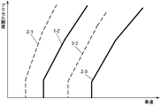
- FIG. 3 is a diagram illustrating an example of the shift map 42 according to the present embodiment.
- the shift map 42 is a map in which a shift stage shift schedule in the transmission mechanism 14 is set based on the accelerator opening and the vehicle speed.
- a plurality of upshift lines and a plurality of downshift lines are set, which are represented by a straight line that goes up to the right (the accelerator opening increases as the vehicle speed increases).
- the upshift line is a line that defines a transition schedule from the low speed stage to the high speed stage between two adjacent speed stages in the transmission mechanism 14, and the downshift line is a schedule for transition from the high speed stage to the low speed stage.
- the speed change mechanism 14 since the speed change mechanism 14 has three speed stages, an upshift line from the first speed stage to the second speed stage, and an upshift line from the second speed stage to the third speed stage.
- a downshift line from the second speed stage to the first speed stage and a downshift line from the third speed stage to the second speed stage are respectively set.
- upshift here means switching of a gear stage to a gear stage having a lower gear ratio based on the gear ratio (reduction ratio) of the gear stage before the gear shift
- downshift means gear shifting. It is assumed that the shift stage is switched to a shift stage having a large ratio.
- the friction engagement element corresponding to the determined target shift speed is engaged with the supply of hydraulic oil, and the target shift speed is formed.
- a target shift speed is determined, and the friction engagement element corresponding to the determined target shift speed is engaged with the supply of hydraulic oil, and a new shift speed is formed.
- one of the frictional engagement elements engaged before the shift is released, and one of the frictional engagement elements released before the shift is engaged.
- the shift stage in the transmission mechanism 14 is switched from the second speed stage to the third speed stage and is upshifted, the first clutch C1 is released and the first brake B1 is engaged.
- the shift speed in the speed change mechanism 14 is switched from the third speed to the second speed and downshifted, the first brake B1 is released and the first clutch C1 is engaged. It will be.
- the engagement and release of the friction engagement elements C1, B1,... Accompanying the upshift or downshift of the gear stage are controlled by the release side hydraulic control unit 37 and the engagement side hydraulic control unit 38.
- the release side hydraulic pressure control unit 37 is a functional unit that controls the hydraulic pressure of hydraulic fluid (release side hydraulic pressure) with respect to the released friction engagement element (release side element).
- the disengagement hydraulic control unit 37 outputs a disengagement control command signal S1 as a control signal to the shift control valve VB, and basically shift control corresponding to the disengagement element according to the disengagement control command signal S1.
- the release side hydraulic pressure is controlled by controlling the operation of the control valve of the valve VB.
- the release side hydraulic control unit 37 controls the release side hydraulic pressure by the release side control command signal S1 only in the initial stage of the shift process TP. Thereafter, the release side hydraulic pressure is controlled based on the actual rotational acceleration AM of the intermediate shaft M irrespective of the release side control command signal S1.
- the engagement side hydraulic control unit 38 is a functional unit that controls the hydraulic pressure (engagement side hydraulic pressure) of the hydraulic fluid with respect to the engaged friction engagement element (engagement side element).
- the engagement side hydraulic control unit 38 outputs an engagement side control command signal S2 as a control signal to the shift control valve VB, and according to the engagement side control command signal S2, shift control corresponding to the engagement side element.
- the engagement side hydraulic pressure is controlled by controlling the operation of the control valve of the valve VB. Details of the release side hydraulic control by the release side hydraulic control unit 37 and the engagement side hydraulic control by the engagement side hydraulic control unit 38 will be described later.
- the limit hydraulic pressure determination unit 39 serves as a reference for determining one or both of a set lower limit value and a set upper limit value of hydraulic pressure of hydraulic oil (release side hydraulic pressure) with respect to the released friction engagement element (release side element). This is a functional unit that determines the limit oil pressure.
- the limit hydraulic pressure determination unit 39 uses the first limit hydraulic pressure PL1 corresponding to the output torque of the rotating electrical machine 12 and the accelerator opening as the limit hydraulic pressure that serves as a reference for determining the setting lower limit value of the release side hydraulic pressure.
- Two limiting oil pressures determined independently of each other are set for the second limiting oil pressure PL2 corresponding to the accelerator opening detected by the detection sensor Se4. Further, the limit oil pressure determination unit 39 sets a predetermined third limit oil pressure PL3 as a limit oil pressure that serves as a reference for determining the setting upper limit value of the release side oil pressure.
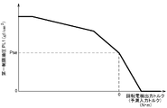
- the first limit hydraulic pressure PL1 is a value corresponding to the magnitude of the output torque of the rotating electrical machine 12 (in this example, determined by the torque command value from the rotating electrical machine control unit 33), and the output torque of the rotating electrical machine 12 Is set to be a value equal to or higher than the stroke end pressure Pse of the disengagement side element.
- the stroke end pressure Pse of the release side element refers to a release side hydraulic pressure immediately before the piston moves until the clearance of the friction material of the release side element disappears and the release side element starts to have a torque capacity.
- FIG. 4 shows an example of a first limit hydraulic pressure map that defines the relationship between the output torque of the rotating electrical machine 12 and the first limit hydraulic pressure PL1. As shown in FIG.
- the first limited hydraulic pressure PL1 is equal to the stroke end pressure Pse of the disengagement side element, and the output torque of the rotating electrical machine 12 is negative. It is set to a value that increases as the direction increases (the regenerative torque increases).
- the first limited hydraulic pressure map is configured as a part of the limited hydraulic pressure map 45 stored in the memory 41.
- the rotating electrical machine 12 outputs negative torque (regenerative torque) to generate electric power by setting the first limit hydraulic pressure PL1
- the release side hydraulic pressure is over the entire speed change process TP.
- the higher the absolute value of the negative torque the higher the hydraulic pressure that is equal to or higher than the stroke end pressure Pse.
- the first restricted hydraulic map shown in FIG. 4 is merely an example, and can be appropriately changed according to vehicle characteristics and the like.
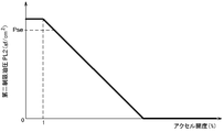
- the second limit hydraulic pressure PL2 is a value corresponding to the accelerator opening, and is equal to or higher than the stroke end pressure Pse of the disengagement element in the low accelerator opening state where the accelerator opening is a predetermined value or less. Is set. Here, a value of “1 to 5%” can be set as the predetermined value. In this example, “1%” is set as the predetermined value, the accelerator opening detected by the accelerator opening detection sensor Se4 is substantially equal to zero, and the depression amount of the accelerator pedal is substantially completely zero. Is the “accelerator low opening state”.
- the engagement pressure of the disengagement element can be made at least larger than zero so that the disengagement element has a torque capacity by setting the second limit oil pressure PL2 to a value that is at least equal to or greater than the stroke end pressure Pse. it can.
- the second limit hydraulic pressure PL2 may be a value less than the stroke end pressure Pse of the disengagement side element.
- the second restricted hydraulic pressure PL2 is set to a value that decreases as the accelerator opening increases.
- FIG. 5 shows an example of a second limited hydraulic pressure map that defines the relationship between the accelerator opening and the second limited hydraulic pressure PL2.
- This second hydraulic limit map is configured as a part of the hydraulic limit map 45 stored in the memory 41. With such a setting of the second limit hydraulic pressure PL2, the release side hydraulic pressure is maintained at a pressure equal to or higher than the stroke end pressure Pse throughout the speed change process TP in the accelerator low opening state.
- the second restricted hydraulic map shown in FIG. 5 is merely an example, and can be appropriately changed according to vehicle characteristics and the like.
- the third limit hydraulic pressure PL3 is set to a predetermined value.
- a tie-up rate that is a ratio at which the engagement side element and the release side element are simultaneously engaged is considered. As the tie-up rate increases, the shift feeling in the shift process TP may deteriorate, and in this embodiment, the third limited hydraulic pressure PL3 is set to maintain the tie-up rate below a predetermined value.
- the third limit hydraulic pressure PL3 is a set upper limit value of the release side hydraulic pressure that maintains the tie-up rate below a predetermined value throughout the entire shift process TP, and functions as a release side upper limit hydraulic pressure (see FIG. 18). reference).
- the first limit hydraulic pressure PL1, the second limit hydraulic pressure PL2, and the third limit hydraulic pressure PL3 determined by the limit hydraulic pressure determination unit 39 are output to the release side hydraulic control unit 37.
- the disengagement hydraulic pressure control unit 37 includes the first limited hydraulic pressure PL1 and the second limited hydraulic pressure PL2 at each point in the shift process TP throughout the shift process TP. While the larger one is regulated to the lower limit value of the release side hydraulic pressure, the release side hydraulic pressure is controlled in a state where the third limit hydraulic pressure PL3 is regulated to the upper limit value of the release side hydraulic pressure. Accordingly, in the speed change process TP, the release side hydraulic pressure is greater than or equal to the larger one of the first limit hydraulic pressure PL1 and the second limit hydraulic pressure PL2 and lower than the third limit hydraulic pressure PL3. To be controlled.
- the input torque prediction unit 40 is a predicted value of the input torque Ti after a predetermined prediction determination reference time (here, TSp) based on a change in the input torque Ti input to the intermediate shaft M as an input member. It is a functional unit that predicts a certain predicted input torque PTi.
- TSp prediction determination reference time
- the engine 11 and the rotating electrical machine 12 are drivingly coupled to the input shaft I as a vehicle driving force source.
- the lockup clutch 22 is engaged, and the input shaft I and the intermediate shaft M rotate together. That is, in this embodiment, basically, the torque input to the input shaft I is input to the intermediate shaft M as it is.
- the total value of the output torque of the engine 11 and the output torque of the rotating electrical machine 12 is set as the input torque Ti.
- the output torque of the engine 11 can be acquired as a torque command value of the engine 11 determined by the engine control unit 32, and similarly, the output torque of the rotating electrical machine 12 can be obtained as the rotating electrical machine control unit 33.
- the torque command value of the rotating electrical machine 12 can take either a positive or negative value depending on whether the output torque of the rotating electrical machine 12 is a driving torque (power running torque) or a regenerative torque.
- the total value of the torque command value of the engine 11 and the torque command value of the rotating electrical machine 12 is set as the input torque Ti.
- the prediction determination reference time TSp an arbitrary value can be set in advance, for example, 0.1 to 1 [sec] or the like is set.
- the predicted determination reference time TSp corresponds to the “determination reference time” in the present invention.
- the input torque prediction unit 40 acquires the input torque change rate RTi at a predetermined period.
- the input torque change rate RTi is the time change rate of the input torque Ti.
- the input torque change rate RTi (n) at the present time point (the time point of the nth cycle; the same shall apply hereinafter) is calculated based on the current input torque Ti (n) and the input torque Ti (n ⁇ 1) one point before the present time point.
- the input torque change amount ⁇ Ti which is the difference from the above, is divided by the period A.
- the derived input torque change rate RTi is provided for deriving the predicted torque change rate QTi.
- the input torque prediction unit 40 calculates the predicted torque change rate QTi at a predetermined period. In deriving the predicted torque change rate QTi, the input torque prediction unit 40 adds the latest input torque change rate RTi and the previous predicted torque change rate QTi at a predetermined ratio to obtain the latest predicted torque change rate QTi. To derive. That is, the latest predicted torque change rate QTi (n) at the current time is the latest input torque change rate RTi (n) at the current time derived based on the above (Equation 1) and the predicted torque at the time one cycle before. The change rate QTi (n ⁇ 1) is added at a predetermined ratio, and is derived by performing an annealing process on the input torque change rate RTi (n).
- k is a predetermined weighting coefficient (0 ⁇ k ⁇ 1).
- the weighting coefficient k is set to a value less than 1, the input torque change rate RTi derived in each calculation cycle is sequentially accumulated and reflected in the subsequent derivation of the predicted torque change rate QTi.
- Equation 2 As can be understood from the above (Equation 2), as the weighting coefficient k is smaller (closer to 0), the cumulative amount of the past input torque change rate RTi becomes smaller when the current predicted torque change rate QTi is derived. As the weighting coefficient k is larger (closer to 1), the current input torque change rate RTi at the current time is more important when the current predicted torque change rate QTi is derived.
- the weighting coefficient k When the weighting coefficient k is set to “1”, the current input torque change rate RTi is used as it is as the current predicted torque change rate QTi. In this embodiment, for example, a value of 0.1 to 0.5 (preferably 0.1 to 0.3) is set as such weighting coefficient k. By setting the weighting coefficient k in this way, it is possible to accurately derive the latest predicted torque change rate QTi by grasping the overall tendency of the input torque Ti over time.
- the input torque prediction unit 40 derives the predicted input torque PTi based on the current input torque Ti and the latest predicted torque change rate QTi. More specifically, the input torque prediction unit 40 derives a predicted input torque PTi by adding a value obtained by multiplying the predicted torque change rate QTi by the prediction determination reference time TSp and the current input torque Ti. That is, the current predicted input torque PTi (n) is obtained by multiplying the current predicted torque change rate QTi (n) by a preset prediction determination reference time TSp and the current input torque Ti (n). Derived by adding.
- the predicted input torque PTi (n) Ti (n) + QTi (n) * TSp (Formula 3)
- the input torque prediction unit 40 sets the input torque Ti as the predicted input torque PTi. That is, the input torque prediction unit 40 according to the present embodiment predicts a value different from the input torque Ti only when the input torque Ti predicted after the prediction determination reference time TSp is smaller than the current input torque Ti.
- the input torque PTi is derived.
- Information on the predicted input torque PTi derived by the input torque prediction unit 40 is output to the switching control unit 36.
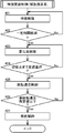
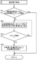
- the switching control unit 36 performs the shift control by switching between the normal shift control and the special shift control according to whether or not the state of the vehicle satisfies a predetermined special shift control transition condition. That is, the switching control unit 36 basically executes the normal shift control, and executes the special shift control when the vehicle state satisfies a predetermined special shift control transition condition.
- the special shift control transition condition is a condition related to the accelerator opening, the predicted input torque PTi, and the shift speed switching direction in the transmission mechanism 14.
- the accelerator opening degree state where the accelerator opening degree detected by the accelerator opening degree detection sensor Se4 is a predetermined value (for example, 1 to 5%) or less, or the prediction input derived by the input torque prediction unit 40
- the target gear position in the speed change mechanism 14 is switched (shifted up) from a gear position with a large gear ratio to a gear position with a small gear ratio. It is set as a control transfer condition.
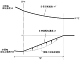
- the engagement side hydraulic pressure control unit 38 preliminarily fills the oil chamber of the engagement side element with hydraulic oil, and then changes the engagement side hydraulic pressure so as to change the rotation speed of the intermediate shaft M at a predetermined target rotation acceleration AT. Control to change.
- the target rotational acceleration of the intermediate shaft M is determined based on the target shift time required for switching the shift speed and the rotation speed change width of the intermediate shaft M before and after the shift speed switching.
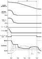
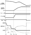
- each of standby control, change rate control, rotational speed control, and release control is performed. It is executed through a control step.
- These standby control, change rate control, rotational speed control, and release control are control of the release side hydraulic pressure by the release side hydraulic control unit 37.
- the engagement side special speed change control is control for changing the engagement side hydraulic pressure so as to appropriately change the actual rotational speed of the intermediate shaft M over the entire speed change process TP.
- the first engagement control and the second engagement control are control of the engagement side hydraulic pressure by the engagement side hydraulic control unit 38.
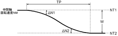
- the target rotational speed NT1 before switching in which the rotational speed NM of the intermediate shaft M as the input shaft of the transmission 2 is the target rotational speed NT before the shift stage is switched.
- the speed change process TP is acquired by the differential rotation acquisition unit 35 from the time when the differential rotation speed ⁇ N1 before the shift stage switching is equal to or higher than a predetermined value. It is set to a period up to the time point when the differential rotation speed ⁇ N2 after the stage change becomes equal to or less than a predetermined value.
- the predetermined value in this case is set to a value that can identify that there is a deviation between the actual rotational speed NM of the intermediate shaft M and the target rotational speeds NT1 and NT2 before and after the shift stage is switched. Therefore, in the present embodiment, the speed change process TP includes the rotation speed NM obtained by multiplying the rotation speed of the output shaft O by the speed ratio after the change of the shift speed and the rotation speed NM of the intermediate shaft M from the time when the disengagement side element starts slipping. The period until the point of time when the difference rotational speed ⁇ N2 between the two and the rotation speed becomes equal to or less than a predetermined value.
- the speed change process TP is a period from the time when the disengagement side element starts to slip to the time when the engagement members (input side rotation member and output side rotation member) on both sides of the engagement side element are synchronized.
- the engagement side element is constituted by a brake
- one of the input side rotation member and the output side rotation member is a non-rotation member (for example, a case (not shown)).
- the end of TP is the time when the rotational speed of the other rotating member becomes substantially zero.
- release side special speed change control standby control is first executed before entering the speed change process TP.
- this standby control when the upshift of the target shift stage is requested based on the accelerator opening and the vehicle speed of the vehicle, the release side hydraulic control unit 37 sets the release side hydraulic pressure in accordance with the output torque until a predetermined time elapses. Use holding pressure. The waiting time at this time is monitored by an internal timer.
- This change rate control is a control executed at the initial stage of the speed change process TP, and the release side hydraulic control unit 37 decreases the release side hydraulic pressure at a change rate according to the magnitude of the output torque of the rotating electrical machine 12.
- the rotating electrical machine 12 is outputting negative torque (regenerative torque)
- the absolute value of the rate of change that decreases the release side hydraulic pressure is smaller as the output torque is smaller (the regenerative torque is larger).
- the absolute value of the rate of change that decreases the disengagement hydraulic pressure is increased.
- the absolute value of the change rate at which the release side hydraulic pressure is reduced at this time is set to a value sufficiently smaller than the absolute value of the change rate in the normal shift control described above, and the release side hydraulic pressure is gradually reduced.
- the disengagement element remains in a semi-engaged state that is not fully engaged or disengaged.
- the engagement member (input side rotation member and output side rotation member) on both sides of the release side element is maintained in a slip state having a predetermined differential rotation speed, and the input side rotation member and output side of the release side element are maintained.
- Driving force is transmitted to and from the rotating member.
- the release side hydraulic control unit 37 controls the release side hydraulic pressure so that the engagement pressure of the release side element becomes equal to or larger than a predetermined value.
- a lower limit value is set for the release side hydraulic pressure during the change rate control so that the engagement pressure of the release side element is greater than or equal to a predetermined value.
- the larger one of the two limiting hydraulic pressures (first limiting hydraulic pressure PL1 and second limiting hydraulic pressure PL2) determined by the limiting hydraulic pressure determination unit 39 is set as the lower limit value of the release side hydraulic pressure.
- the release side hydraulic pressure during the change rate control is maintained at a pressure equal to or higher than the first limit hydraulic pressure PL1 and equal to or higher than the second limit hydraulic pressure PL2.
- the second limited hydraulic pressure PL2 is set to be a value equal to or higher than the stroke end pressure Pse of the disengagement side element in the accelerator low opening state where the special shift control is executed. Therefore, in the present embodiment, the release-side element is in the half-engaged state during the execution of the special speed change control, and is maintained in the slip state.
- the first limited hydraulic pressure PL1 is set to a value that increases as the output torque of the rotating electrical machine 12 increases in the negative direction (the regenerative torque increases).
- the release side hydraulic pressure during the special speed change control is basically maintained at the second limit hydraulic pressure PL2 or higher, and according to the magnitude of the regenerative torque (negative torque) output by the rotating electrical machine 12.
- the first limit oil pressure PL1 is larger than the second limit oil pressure PL2
- the first limit oil pressure PL1 is maintained at or above the first limit oil pressure PL1.
- an upper limit value is set for the release side hydraulic pressure in the speed change process TP so that the engagement pressure of the release side element becomes a magnitude equal to or less than a predetermined value.
- the predetermined third limit oil pressure PL3 is set to the upper limit value of the release side oil pressure. Accordingly, the release side hydraulic pressure in the speed change process TP is maintained at a pressure equal to or lower than the third limit hydraulic pressure PL3.
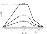
- the switching control unit 36 monitors the progress ⁇ of the speed change operation in the speed change process TP throughout the speed change process TP.
- the degree of progress ⁇ is an index indicating how much the shift of the shift speed has progressed in the shift process TP.
- the degree of progress ⁇ is derived as the ratio of the difference in rotational speed between the actual rotational speed NM of the intermediate shaft M during the shifting operation.
- the target rotational speeds NT1 and NT2 of the intermediate shaft M before and after the shift speed change are set to the actual rotational speed NO of the output shaft O detected by the output shaft rotational speed sensor Se3 as described above. It is derived by multiplying the gear ratio.
- the actual rotational speed NM of the intermediate shaft M is detected by the intermediate shaft rotational speed sensor Se2. Therefore, the actual rotational speed NM of the intermediate shaft M detected by the intermediate shaft rotational speed sensor Se2, the actual rotational speed NO of the output shaft O detected by the output shaft rotational speed sensor Se3, and the shift speeds before and after switching.
- the degree of progression ⁇ is derived based on the gear ratio.
- the change rate control is performed up to the switching point, with the time when the degree of progress ⁇ reaches a predetermined ratio as the switching point.
- the time point when the speed change operation has progressed 50% (the degree of progress ⁇ becomes 0.5) is taken as the switching point, and up to the switching point.
- Change rate control is executed.
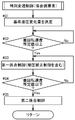
- whether or not the special shift control transition condition is satisfied is determined based on the accelerator opening detected by the accelerator opening detection sensor Se4 and the switching direction of the target gear stage in the transmission mechanism 14. It has become.
- the target gear position in the transmission mechanism 14 is switched from a gear position with a large gear ratio to a gear position with a small gear ratio (up-shifted). ), It is determined that the special shift control transition condition is satisfied. In other cases, it is determined that the special shift control transition condition is not satisfied.
- the rotational speed control is executed next.
- the release side hydraulic control unit 37 changes the release side hydraulic pressure so that the rotational speed NM of the intermediate shaft M becomes the target rotational speed NT at each point in the speed change process TP.
- a target shift time (in this case, Tt) that represents a target time required for shifting the gear position is set in advance, and the shift operation is performed when the target shift time Tt has elapsed after the start of the shift operation. Will be completed.
- the target shift time Tt is stored in the memory 41 as target shift time data 44.
- the target rotational speed NT of the intermediate shaft M at each time point is determined based on the target shift time Tt and the rotational speed change width W that is the difference between the rotational speeds of the intermediate shaft M before and after the shift stage switching.
- the target rotational speed NT at each point in the speed change process TP is set so as to draw a temporal trajectory that hardly causes a change in behavior in the vehicle when the speed change is performed. More specifically, the target rotational speed NT at each point in the speed change process TP has a temporal trajectory such that the absolute value of the time change rate of the target speed NT decreases toward the end of the speed change process TP. Is set.
- the target rotational speed NT at each time point is such that the rotational speed of the intermediate shaft M from the time when the rotational speed control is started to the time when the speed change operation is completed draws a temporal trajectory represented by a quadratic curve.
- a target rotational acceleration AT (target rotational speed change rate) at each time point is further derived from the target rotational speed NT at each time point set as described above.
- the absolute value of the target rotational acceleration AT at each time point is directed toward the end point of the shift operation. It is set so that it gradually decreases linearly and eventually becomes zero.
- it is good also as a structure which sets the target rotational acceleration AT in each time point also considering the acceleration of a vehicle.
- the release side hydraulic control unit 37 changes the release side hydraulic pressure so that the actual rotational acceleration AM of the intermediate shaft M acquired by the rotational acceleration acquisition unit 34 follows the target rotational acceleration AT at each time point. That is, as shown in FIG. 8, the disengagement hydraulic control unit 37 compares the target rotational acceleration AT at each time point of the intermediate shaft M with the actual rotational acceleration AM, and when there is a deviation between them. Changes the release-side hydraulic pressure so that the actual rotational acceleration AM of the intermediate shaft M changes in a direction to cancel the deviation. In this way, in the latter half of the speed change process TP, the rotational speed NM of the intermediate shaft M can be smoothly shifted to the target rotational speed NT2 after switching. During this time, the disengagement side element is maintained in a semi-engaged state that is not completely engaged and disengaged as described above, and is maintained in a slip state.
- the differential rotational speed ⁇ N2 between the post-switching target rotational speed NT2 acquired by the differential rotational acquisition unit 35 and the actual rotational speed NM of the intermediate shaft M. Is executed until the value becomes equal to or less than a predetermined value.
- a predetermined value at this time a value equal to a reference value for determining the end of the speed change process TP is set in this example. Therefore, in this example, the timing of the end of the rotational speed control is equal to the timing of the end of the speed change process TP.
- release control is executed next.
- the release side hydraulic control unit 37 reduces the release side hydraulic pressure at a rate of change equal to the rate of change of the release side hydraulic pressure in the normal shift control, and rapidly makes it zero. As a result, the release-side element is quickly released completely.
- the engagement side oil pressure control unit 38 first sets a reference oil pressure change amount ⁇ Pb as a reference for changing the engagement side oil pressure before entering the speed change process TP. decide.
- the reference hydraulic pressure change amount ⁇ Pb is a hydraulic pressure change amount required to change the rotational speed of the intermediate shaft M at a predetermined target rotational acceleration AT.
- the reference hydraulic pressure change amount ⁇ Pb is derived as a multiplication value of the target rotational acceleration AT and a predetermined coefficient.
- the target rotational acceleration AT of the intermediate shaft M is a preset target shift time (in this case, Tt) that represents the target time required for shifting the gear, as described above, and the intermediate before and after the shifting of the gear.
- the reference hydraulic pressure change amount ⁇ Pb is also determined based on the target shift time Tt and the rotational speed change width W.
- the engagement-side hydraulic pressure control unit 38 Based on the derived target rotational acceleration AT, the engagement-side hydraulic pressure control unit 38 adjusts the hydraulic pressure of the hydraulic oil (with respect to the engagement-side element) so that the actual rotational acceleration AM of the intermediate shaft M follows the target rotational acceleration AT.
- the first engagement control for changing the engagement side hydraulic pressure) is executed.
- the engagement side hydraulic control unit 38 uses the engagement side hydraulic pressure at the start of the shift process TP as a reference, and the degree of progress ⁇ of the shift process TP The engagement side hydraulic pressure is changed based on a predetermined change coefficient G set in advance according to the output torque of the rotating electrical machine 12 and a reference hydraulic pressure change amount ⁇ Pb.
- FIG. 6 shows an example of a change coefficient map 46 that defines the relationship between the degree of progression ⁇ of the speed change process TP and the output torque of the rotating electrical machine 12 and the change coefficient G.
- the horizontal axis and the vertical axis indicate the progress ⁇ and the change coefficient G, respectively, and the progress ⁇ for each of a plurality (here, four) representative values related to the output torque of the rotating electrical machine 12.
- a plurality of polygonal graphs showing the relationship between the change coefficient G and the change coefficient G are shown.
- the speed change process TP is divided into a plurality of stages (in this example, three stages of a first stage ⁇ 1, a second stage ⁇ 2, and a third stage ⁇ 3) set according to the degree of progress ⁇ .
- the change coefficient G is the first stage in the speed change process TP under the condition that the output torque of the rotating electrical machine 12 is maintained at a constant value throughout the speed change process TP.
- the value increases as the speed change process TP progresses
- the third stage ⁇ 3, which is the last stage of the speed change process TP is set to a value that decreases as the speed change process TP progresses.
- the first stage ⁇ 1 is a stage where the degree of progress ⁇ of the speed change process TP is equal to or less than a predetermined value, and in this example, the period of 0 ⁇ ⁇ ⁇ 0.4 is the first stage ⁇ 1.
- the third stage ⁇ 3 is a stage in which the degree of progression ⁇ of the speed change process TP is equal to or greater than a predetermined value.
- the period of 0.6 ⁇ ⁇ ⁇ 1 is the third stage ⁇ 3.
- the change coefficient G depends on the progress degree ⁇ of the speed change process TP. It is set to a constant value.
- the rate of change (here, the rate of decrease) of the change coefficient G with respect to the degree of progression ⁇ is the first half of the second half ⁇ 32 of the third stage ⁇ 3.
- the absolute value of the change rate (in this case, the rate of increase) of the change coefficient G with respect to the degree of progression ⁇ in the first stage ⁇ 1 is the change rate (here, the rate of decrease) of the change coefficient G in the first half ⁇ 31 of the third stage ⁇ 3.
- the change coefficient G increases as the output torque of the rotating electrical machine 12 changes in the positive direction when the output torque of the rotating electrical machine 12 is negative under the condition that the degree of progression ⁇ of the speed change process TP is equal. (A value that decreases as the output torque of the rotating electrical machine 12 changes in the negative direction).
- FIG. 6 shows only the relationship when the output torque of the rotating electrical machine 12 is negative (including the case of zero), but in this example, the relationship when the output torque of the rotating electrical machine 12 is positive is shown. The relationship in the case of zero is the same.
- FIG. 6 shows only the relationship regarding the four representative values related to the output torque of the rotating electrical machine 12, but it is also possible to have a configuration that defines more relationships regarding the output torque.
- the change coefficient map shown in FIG. 6 is merely an example, and can be appropriately changed according to vehicle characteristics and the like.
- the engagement side hydraulic pressure control unit 38 uses the engagement side hydraulic pressure at the start of the speed change process TP as a reference, a change coefficient G determined based on the degree of progress ⁇ of the speed change process TP and the output torque of the rotating electrical machine 12, and a reference oil pressure.
- the engagement side hydraulic pressure is changed based on the change amount ⁇ Pb. That is, in this example, the multiplication value obtained by multiplying the reference hydraulic pressure change amount ⁇ Pb and the change coefficient G is used as the change amount of the engagement side hydraulic pressure according to the degree of progress ⁇ of the speed change process TP and the output torque of the rotating electrical machine 12.
- the engagement side hydraulic pressure control unit 38 changes the actual engagement side hydraulic pressure so as to follow the command value of the engagement side hydraulic pressure.
- the change of the engagement side hydraulic pressure is based on the reference hydraulic pressure change amount ⁇ Pb and according to the degree of progress ⁇ of the speed change process TP and the output torque of the rotating electrical machine 12.
- the engagement side hydraulic pressure has a larger variation range as the absolute value of the negative torque (regenerative torque) output from the rotating electrical machine 12 is smaller, and increases, is fixed, decreases, and slowly decreases as the speed change process TP progresses.
- the engagement-side hydraulic pressure at the start of the speed change process TP is a pressure immediately before the start of engagement that allows the engagement-side element to be quickly engaged by slightly increasing the engagement-side hydraulic pressure.
- Such first engagement control is executed in synchronization with a decrease in the release side hydraulic pressure by the release side special speed change control.
- engagement side hydraulic pressure controlled by the engagement side hydraulic control unit 38 as described above is referred to as an “engagement side reference hydraulic pressure PES” (see FIG. 9).
- This engagement side reference hydraulic pressure PES is a concept that basically represents a hydraulic pressure whose magnitude changes in accordance with the degree of progression ⁇ of the speed change process TP. However, depending on the magnitude of the negative torque (regenerative torque) output by the rotating electrical machine 12, there may be a constant value regardless of the degree of progression ⁇ of the speed change process TP (see FIGS. 6 and 9).
- the engagement side hydraulic pressure is controlled according to the engagement side reference hydraulic pressure PES as described above, the rotation speed of the intermediate shaft M, which tends to become slow by maintaining the disengagement side element in the slip state, is reduced. It is easy to assist the lowering by the change of the engagement side hydraulic pressure and to appropriately end the shift operation within the target shift time Tt.
- the release side hydraulic control unit 37 releases the release side oil pressure within a predetermined slip determination reference time (here, TSs) based on the time point when the release side oil pressure is reduced.
- the engagement side hydraulic pressure control unit 38 performs the pressure increase correction control for increasing the engagement side hydraulic pressure until the slip of the release side element is detected.
- This pressure increase correction control is an engagement side hydraulic pressure control executed as part of the first engagement control described above, and is executed independently of the engagement side hydraulic pressure control according to the engagement side reference hydraulic pressure PES. Is done. That is, the engagement side hydraulic pressure control unit 38 controls the engagement side hydraulic pressure in accordance with the engagement side reference hydraulic pressure PES, but still the release side element starts to slip within the slip determination reference time TSs after the start of the decrease of the release side hydraulic pressure. If not, a pressure increase correction control is executed, and a pressure increase correction for further increasing the engagement side hydraulic pressure with respect to the engagement side reference hydraulic pressure PES is performed.
- FIG. 9 is an explanatory diagram for explaining the pressure increase correction control according to the present embodiment.
- the expected remaining shift time, the rotational speed NM of the intermediate shaft M, the engagement side hydraulic pressure and the release side hydraulic pressure are shown in order from the top.
- the engagement side hydraulic pressure the engagement side reference hydraulic pressure PES is indicated by a one-dot chain line, and the engagement side hydraulic pressure after the pressure increase correction is indicated by a solid line.
- the engagement-side reference hydraulic pressure PES is maintained at a constant value that does not change, but when the engagement-side reference hydraulic pressure PES changes over time, the engagement-side reference hydraulic pressure at each time point A value obtained by adding the pressure increase correction pressure ⁇ PE at each time point to the hydraulic pressure PES is the engagement side oil pressure at each time point after the pressure increase correction.
- the engagement side hydraulic pressure control unit 38 increases the engagement side hydraulic pressure at a constant pressure increase rate with respect to the engagement side reference hydraulic pressure PES. .
- Such pressure increase correction control is executed until the release side element starts to slip.
- the time when the disengagement side element starts to slip coincides with the start of the speed change process TP, and in the present embodiment, based on the differential rotation speed ⁇ N1 before the shift speed change acquired by the differential rotation acquisition unit 35, It is possible to determine when the release element starts to slip.
- the engagement side hydraulic pressure control unit 38 After it is detected that the disengagement side element has started slipping by executing the pressure increase correction control, the engagement side hydraulic pressure control unit 38 increases the amount increased by the pressure increase correction control before the end of the shift process TP.
- the engagement side hydraulic pressure pressure increase correction pressure ⁇ PE
- the engagement side hydraulic pressure is gradually canceled and finally lowered to the engagement side reference hydraulic pressure PES.
- the engagement-side hydraulic control unit 38 is engaged on the engagement side at the pressure increase end time EP according to the predicted time from the current time to the predetermined pressure increase end time EP set before the end of the speed change process TP.
- the engagement side oil pressure is gradually reduced so that the oil pressure becomes the engagement side reference oil pressure PES.
- the engagement side hydraulic control unit 38 sets the pressure increase correction pressure ⁇ PE at the time when the disengagement side element starts slipping as the reference pressure increase correction pressure ⁇ PEb, and the expected remaining when the disengagement side element starts slipping.
- the pressure increase at each point in the speed change process TP where Ta is the speed change time, Tb is the expected remaining speed change time at the present time, and Tx is a predetermined margin time set between the pressure increase end point EP and the time point at which the speed change process TP ends
- Correction pressure ⁇ PE ⁇ PE ⁇ PEb * (Tb ⁇ Tx) / (Ta ⁇ Tx) (Formula 4) As follows.
- the reference pressure increase correction pressure ⁇ PEb, the expected remaining shift time Ta, and the margin time Tx are constants, and the expected remaining shift time Tb is a variable. Then, the engagement side hydraulic control unit 38 sets the engagement side reference hydraulic pressure PES and the pressure increase correction pressure ⁇ PE at each time point derived according to the above (Equation 4) to a value obtained by adding the engagement side reference hydraulic pressure PES. Control the combined hydraulic pressure.
- the pressure increase correction pressure ⁇ PE is reduced according to the predicted time (Tb ⁇ Tx) from the current time to the pressure increase end time EP, so that the pressure increase end time before the end point of the speed change process TP is reached.
- the pressure increase correction pressure ⁇ PE can be surely eliminated.
- the engagement side hydraulic pressure is high by the amount of pressure increase correction, and the rotational acceleration AM (deceleration in this case) of the intermediate shaft M is also relatively large.
- the expected remaining shift time Tb decreases relatively rapidly. Therefore, even when the start of the slip of the release side element is delayed, the shift time after the start of the slip of the release side element can be shortened to prevent the shift time from being extended as a whole.
- the expected remaining shift time Ta when the disengagement side element starts to slip is equal to the target shift time Tt described above. Further, the expected remaining shift time Tb at each time point is obtained by dividing the difference rotation speed ⁇ N2 by the rotation acceleration AM based on the difference rotation speed ⁇ N2 after the shift speed change at that time and the rotation acceleration AM of the intermediate shaft M. Can be obtained as a division value.
- the pressure increase correction control is not executed, and the engagement-side hydraulic control unit 38 The engagement side hydraulic pressure is controlled according to the side reference hydraulic pressure PES as it is.
- the first engagement control is the differential rotation between the post-switch target rotation speed NT2 acquired by the differential rotation acquisition unit 35 and the actual rotation speed NM of the intermediate shaft M.
- the process is executed until the speed ⁇ N2 becomes a predetermined value or less.
- a reference value for determining the end of the rotation speed control and a reference value for determining the end of the speed change process TP are set in this example. Therefore, in this example, the timing of the end of the first engagement control is equal to the timing of the end of the rotational speed control and the speed change process TP.
- the second engagement control is executed next.
- the engagement side hydraulic control unit 38 is engaged so that the engagement side element is brought into a completely engaged state after the differential rotation speed ⁇ N2 becomes equal to or less than a predetermined value and the speed change process TP is completed. Control the combined hydraulic pressure.
- the engagement side hydraulic pressure control unit 38 increases the engagement side hydraulic pressure to the full engagement pressure at once after the shift process TP is completed.
- the limit hydraulic pressure determination unit 39 sets a pressure having a value corresponding to the magnitude of the predicted input torque PTi as the first limit hydraulic pressure PL1.
- the limit hydraulic pressure determination unit 39 sets the pressure that is equal to the stroke end pressure Pse of the disengagement element at the time when the predicted input torque PTi is zero and increases as the predicted input torque PTi increases in the negative direction. It is set as the limited hydraulic pressure PL1 (see the brackets in FIG. 4).
- FIG. 10 is a flowchart showing an overall processing procedure of the shift control processing of the vehicle drive device 1 according to the present embodiment.
- FIG. 11 is a flowchart showing a procedure of a release-side special shift control process that is a special shift control process for the release-side element in the special shift control process of Step # 06 of FIG.
- FIG. 12 is a flowchart showing the processing procedure of the engagement-side special shift control process, which is a special shift control process for the engagement-side element, in the special shift control process of step # 06 in FIG.
- the procedure of the shift control process of the vehicle drive device 1 described below is executed by the functional units 32 to 40 of the control unit 31.
- the arithmetic processing unit included in the control unit 31 operates as a computer that executes the program configuring the function units 32 to 40 described above.
- the output torque, accelerator opening, and predicted input torque PTi of the rotating electrical machine 12 are acquired (step # 01).
- the output torque of the rotating electrical machine 12 is acquired as a torque command value determined by the rotating electrical machine control unit 33, and the accelerator opening is detected and acquired by the accelerator opening detection sensor Se4.
- the predicted input torque PTi is derived and acquired by the input torque prediction unit 40.
- the limit hydraulic pressure determination unit 39 determines the first limit hydraulic pressure PL1 according to the output torque of the rotating electrical machine 12 based on the acquired output torque of the rotating electrical machine 12, and based on the acquired accelerator opening degree.
- a second limited hydraulic pressure PL2 corresponding to the accelerator opening is determined, and a third limited hydraulic pressure PL3 that is a predetermined value is set (step # 02).
- a special shift control transition condition That is, whether or not a negative torque prediction is established (step # 03), whether or not the accelerator is in a low opening degree (step # 04), and whether or not an upshift request for a target gear position in the transmission mechanism 14 has been made (Step # 05) is determined.
- a predetermined value 1% in this example
- Step # 06 When it is determined that the negative torque prediction establishment state (step # 03: Yes) or the accelerator low opening state (step # 04: Yes) and it is determined that an upshift request for the target gear position has been made. (Step # 05: Yes), the switching control unit 36 executes special shift control (Step # 06). The detailed processing procedure of the special speed change control will be described next. On the other hand, if it is determined that it is not in the negative torque prediction establishment state (step # 03: No) and is not in the accelerator low opening state (step # 04: No), or that an upshift request for the target gear stage has not been made. When it is determined (step # 05: No), the switching control unit 36 performs normal shift control (step # 07). In this normal shift control, the disengagement element is quickly released at the initial stage of the shift process TP, and the engagement element is completely engaged through the slip state. Then, while the vehicle is traveling, the processes of steps # 01 to # 07 are sequentially repeated.
- the special speed change control process includes a release side special speed change control process for the release side element and an engagement side special speed change control process for the engagement side element.
- step # 21 standby control
- step # 22: Yes the change rate control is executed (step # 23).
- the release side hydraulic pressure is reduced at a change rate according to the magnitude of the output torque of the rotating electrical machine 12 (or the predicted input torque PTi in the negative torque prediction establishment state).
- the change rate control is continuously executed as long as the special shift control transition condition is satisfied, and in parallel with this, it is determined whether or not the shift process TP has reached the switching point (step # 24).
- the time point at which the shifting operation has progressed 50% is the switching point.
- step # 24 No
- the change rate control is continuously executed.
- rotation speed control is executed (step # 25).
- the release side hydraulic pressure is changed so that the actual rotational acceleration AM of the intermediate shaft M as the input shaft of the transmission 2 follows the target rotational acceleration AT at each time point.
- the rotational speed control is continuously executed as long as the special speed change control transition condition is satisfied, and in parallel with this, it is determined whether or not the differential rotational speed ⁇ N2 is equal to or less than a predetermined value (step # 26).
- the predetermined value in this case is set to a value that can identify that there is a deviation between the actual rotational speed of the intermediate shaft M and the target rotational speed NT2 after the shift stage is switched.
- the rotational speed control is continuously executed.
- the rotational speed difference ⁇ N2 becomes less than the predetermined value (Step # 26: Yes)
- Release control is executed (step # 27).
- the release control is also executed when the special shift control transition condition is not satisfied during the execution of the change rate control or the rotation speed control (step #). 27). The disengagement side special speed change control process is thus completed.
- the reference hydraulic pressure change amount ⁇ Pb is determined (step # 31).
- the reference hydraulic pressure change amount ⁇ Pb is determined based on the target shift time Tt and the rotational speed change width W.
- the predetermined value in this case is set to a value that can identify that there is a deviation between the actual rotational speed of the intermediate shaft M and the target rotational speed NT1 before the shift stage is switched. .
- step # 32 When it is determined that the differential rotation speed ⁇ N1 has become equal to or greater than a predetermined value (step # 32: Yes), the first engagement control is executed next and in parallel with the first engagement control under a predetermined condition. Pressure increase correction control is executed (step # 33).
- the engagement side oil pressure is changed based on the reference oil pressure change amount ⁇ Pb and in accordance with the engagement side reference oil pressure PES corresponding to the degree of progression ⁇ of the speed change process TP and the output torque of the rotating electrical machine 12.
- the detailed processing procedure of the pressure increase correction control will be described next.
- the first engagement control is continuously executed as long as the special shift control transition condition is satisfied, and in parallel with this, it is determined whether or not the differential rotation speed ⁇ N2 is equal to or less than a predetermined value (step # 34). ).
- Step # 34: No While the rotational speed difference ⁇ N2 is larger than the predetermined value (Step # 34: No), the rotational speed control is continuously executed. When the rotational speed difference ⁇ N2 becomes less than the predetermined value (Step # 34: Yes), Second engagement control is executed (step # 35). In the second engagement control, after the differential rotation speed ⁇ N2 becomes equal to or less than a predetermined value and the speed change process TP is completed, the engagement side hydraulic pressure is increased to the full engagement pressure at once. The engagement side special speed change control process is thus completed. Although not shown in the flowchart of FIG. 12, when the special shift control transition condition is not satisfied during the execution of the first engagement control, the engagement-side special shift control process is terminated and the normal shift control process is terminated. The engagement side hydraulic pressure control in the shift control (step # 07) is executed.
- step # 41 first, whether or not the release-side element has started slipping within a predetermined slip determination reference time TSs with reference to the time point when the release-side hydraulic control unit 37 reduces the release-side hydraulic pressure. Is determined (step # 41).
- the determination of the slip start time of the disengagement element can be made based on the differential rotation speed ⁇ N1 before the shift stage is switched. If it is determined that the disengagement side element has started slipping within the slip determination reference time TSs (step # 41: Yes), the substantial content of the pressure increase correction control is not executed, and the pressure increase correction is performed as it is.
- the control process ends.
- step # 41: No the substantial content of the pressure increase correction control is executed. That is, the engagement side hydraulic pressure control unit 38 further increases the engagement side hydraulic pressure at a constant pressure increase rate with reference to the engagement side reference hydraulic pressure PES (step # 42). Such pressure increase correction of the engagement side hydraulic pressure is continuously executed until the disengagement side element actually starts slipping (step # 43). When it is determined that the release-side element has started slipping (step # 43: Yes), the engagement-side hydraulic control unit 38 then engages according to the predicted time from the current time point to the pressure increase end point EP.
- step # 44 The side oil pressure is reduced (step # 44), and finally the engagement side oil pressure is set to the engagement side reference oil pressure PES at the pressure increase end point EP.
- the pressure increase correction control process is thus completed, and the process returns to step # 33 in the engagement side special speed change control process.
- FIG. 14 is a timing chart showing an example of a case where a shift operation is performed by the normal shift control.
- FIG. 14 shows the case where the upshift is performed by the speed change mechanism 14 when the accelerator opening of the vehicle is larger than the accelerator opening (1% in this example) that defines the low accelerator opening state (power).
- An example of on-upshifting is shown.
- the upshift request is turned on at time T11 while the accelerator opening is maintained at a predetermined magnitude. From time T11 to time T12, the disengagement side oil pressure is maintained at a holding pressure corresponding to the output torque, and the engagement side oil pressure is maintained at a predetermined maintenance pressure after the preliminary filling is completed.
- the disengagement hydraulic pressure is rapidly decreased, and the disengagement element is quickly disengaged at the initial stage of the speed change process TP.
- the engagement side hydraulic pressure is changed so that the rotation speed NM of the intermediate shaft M is changed at a predetermined target rotation acceleration AT.
- the engagement side hydraulic pressure is increased to the full engagement pressure, the engagement side element is brought into the complete engagement state, and the speed change process TP is completed.
- the accelerator opening and the positive torque output from the rotating electrical machine 12 are maintained at relatively large values throughout the speed change process TP, and the first limit hydraulic pressure PL1 and the second limit hydraulic pressure PL2 are the release side elements. It is set to a value sufficiently smaller than the stroke end pressure Pse. Therefore, the release side hydraulic pressure changes without being regulated by the first limit hydraulic pressure PL1 or the second limit hydraulic pressure PL2.
- FIG. 15 is a timing chart showing an example of a case where a shift operation is performed by special shift control.
- the predicted input torque PTi substantially matches the output torque of the rotating electrical machine 12.
- FIG. 15 shows an example in which an upshift is performed by the speed change mechanism 14 (power-off upshift) in a low accelerator position where the accelerator opening of the vehicle is a predetermined value or less.
- the special shift control is executed.
- the accelerator opening becomes zero at time T21
- the output torque of the rotating electrical machine 12 gradually decreases and becomes zero at time T22.
- the upshift request is turned on.
- the driver does not perform a brake operation, and the output torque of the rotating electrical machine 12 is maintained at zero throughout the entire speed change process TP.
- the second limited hydraulic pressure PL2 is larger than the first limited hydraulic pressure PL1 and larger than the stroke end pressure Pse of the disengagement side element over the entire speed change process TP.
- the disengagement hydraulic pressure is maintained at a holding pressure corresponding to the output torque, and the engagement hydraulic pressure is maintained at a predetermined maintenance pressure after the preliminary filling is completed.
- the disengagement hydraulic pressure is controlled so that the disengagement element is maintained in the slip state throughout the speed change process TP.
- change rate control is executed from time T22 to T24, and the release-side hydraulic pressure is gradually reduced at a reduced pressure change rate corresponding to the magnitude of the negative torque (regenerative torque) output by the rotating electrical machine 12. .
- the release side hydraulic pressure reaches the second limited hydraulic pressure PL2 which is the larger one of the first limited hydraulic pressure PL1 and the second limited hydraulic pressure PL2 at time T23, it is not further reduced, and from time T23.
- the release side hydraulic pressure is maintained at the second limit hydraulic pressure PL2 until T24. Then, at time T24, when the speed change operation proceeds 50%, that is, at the switching point, the change rate control is switched to the rotation speed control.
- the disengagement hydraulic pressure is changed so that the actual rotational acceleration AM of the intermediate shaft M follows the target rotational acceleration AT at each time point.
- the release side hydraulic pressure once rises from time T24 to T25, and then changes so as to maintain a substantially constant pressure.
- the engagement side hydraulic pressure is synchronized with the change in the release side hydraulic pressure so that the actual rotational acceleration AM of the intermediate shaft M follows the target rotational acceleration AT. Changed.
- the increase, the fixed, the lower, and the fixed are increased with a relatively large change width as the speed change process TP progresses.
- the engagement-side hydraulic pressure (engagement-side reference hydraulic pressure PES) changes in this manner.
- FIG. 16 is a timing chart showing another example of the case where the shift operation is performed by the special shift control.
- the predicted input torque PTi substantially matches the output torque of the rotating electrical machine 12.
- FIG. 16 shows an example of a case where an upshift is performed by the speed change mechanism 14 (power-off upshift) in a low accelerator position where the accelerator opening of the vehicle is a predetermined value or less, as in FIG. Yes.
- the special shift control is executed.
- the accelerator opening becomes zero at time T31
- the output torque of the rotating electrical machine 12 gradually decreases and becomes zero at time T32.
- the upshift request is on.
- the brake operation by the driver is performed after time T32, and based on the deceleration request by this brake operation, the rotating electrical machine 12 outputs a negative torque to brake the vehicle and regenerates itself. (Off-up regeneration).
- the negative torque output from the rotating electrical machine 12 gradually increases as the speed change process TP progresses, and the first limit hydraulic pressure PL1 gradually increases accordingly.
- the second restricted hydraulic pressure PL2 Prior to time T34, the second restricted hydraulic pressure PL2 is larger than the first restricted hydraulic pressure PL1, and after the time T34, the first restricted hydraulic pressure PL1 is larger than the second restricted hydraulic pressure PL2. In any case, it is larger than the stroke end pressure Pse of the release side element.
- the disengagement side oil pressure is maintained at a holding pressure corresponding to the output torque, and the engagement side oil pressure is maintained at a predetermined maintenance pressure after the preliminary filling is completed. Thereafter, from time T33 to T36, the disengagement hydraulic pressure is controlled so that the disengagement element is maintained in the slip state throughout the speed change process TP.
- change rate control is executed from time T33 to T35, and the release side hydraulic pressure is gradually reduced at a reduced pressure change rate corresponding to the magnitude of the negative torque (regenerative torque) output by the rotating electrical machine 12. .
- the disengagement hydraulic pressure reaches the first limit hydraulic pressure PL1, which is the larger one of the first limit hydraulic pressure PL1 and the second limit hydraulic pressure PL2, so that it is not further reduced and time T34 is reached.
- the release side hydraulic pressure is maintained at the first limit hydraulic pressure PL1. Note that, as described above, the first limit hydraulic pressure PL1 gradually increases as the speed change process TP proceeds, and accordingly, the release side hydraulic pressure also gradually increases.
- the change rate control is switched to the rotation speed control at the time when the speed change operation has progressed 50%, that is, at the switching point.
- the disengagement hydraulic pressure is changed so that the actual rotational acceleration AM of the intermediate shaft M follows the target rotational acceleration AT at each time point.
- the release side hydraulic pressure rises once from time T35 to T36 and then changes so as to maintain a substantially constant pressure.
- the engagement side hydraulic pressure is synchronized with the change of the release side hydraulic pressure so that the actual rotational acceleration AM of the intermediate shaft M follows the target rotational acceleration AT. Changed.
- the engagement-side hydraulic pressure increases with a relatively small change width as the speed change process TP progresses. It changes in a fixed-decreasing-fixed manner. That is, as can be understood by comparing FIG. 15 and FIG. 16, the engagement-side hydraulic pressure has a smaller change width than the case where the output torque of the rotating electrical machine 12 is maintained at zero as the speed change process TP progresses. Has changed.
- FIG. 17 is a timing chart showing another example of the case where the shift operation is performed by the special shift control.
- the predicted input torque PTi changes at a level lower than the output torque of the rotating electrical machine 12.
- an upshift is performed by the transmission mechanism 14 in a negative torque prediction establishment state in which the predicted input torque PTi predicted to be input to the input shaft I after the prediction determination reference time TSp is a negative value.
- An example of the case (power-off upshift) is shown. In this case as well, the special shift control transition condition is satisfied, so that the special shift control is executed.
- the accelerator opening is maintained at a predetermined value of zero or more and is not in the accelerator low opening state, but at time T41, the predicted input torque becomes zero or less and negative torque The prediction is established. Therefore, after time T41, the special shift control is executed.
- the detailed content of this special speed change control is similar to that described with reference to FIG.
- the first limited hydraulic pressure PL1 is different from the example of FIG. 16 in that it is set based on the predicted input torque PTi rather than the output torque (regenerative torque) of the rotating electrical machine 12. Since the other points are the same as those in the example of FIG. 16, detailed description thereof is omitted here.
- FIG. 18 is a timing chart showing another example of the case where the shift operation is performed by the special shift control.
- the predicted input torque PTi substantially matches the output torque of the rotating electrical machine 12.
- FIG. 18 shows an example of a case where the upshift is performed by the speed change mechanism 14 (power-off upshift) in a low accelerator opening state where the accelerator opening of the vehicle is equal to or less than a predetermined value, as in FIGS. It is shown.
- the special shift control is executed.
- the accelerator opening becomes zero at time T51
- the output torque of the rotating electrical machine 12 gradually decreases, becomes negative at time T52, and the rotating electrical machine 12 is in a state of performing regeneration (off-up regeneration).
- the upshift request is turned on.
- the second limit hydraulic pressure PL2 is larger than the first limit hydraulic pressure PL1 and larger than the stroke end pressure Pse of the disengagement side element over the entire speed change process TP.
- the disengagement side oil pressure is maintained at a holding pressure corresponding to the output torque, and the engagement side oil pressure is maintained at a predetermined maintenance pressure after the preliminary filling is completed.
- the disengagement side hydraulic pressure is lowered so that the disengagement side element is maintained in the slip state throughout the speed change process TP.
- the rotational speed of the intermediate shaft M has not decreased to such an extent that the predetermined differential rotational speed ⁇ N1 occurs for a while after the time T52 when the release-side hydraulic pressure is started to decrease. That is, the release-side element does not slip for a while after the release-side hydraulic pressure is reduced. Therefore, in this example, the pressure increase to further increase the engagement side hydraulic pressure with respect to the engagement side reference hydraulic pressure PES, starting at time T53 after the predetermined time (slip determination reference time TSs) has elapsed after the release side hydraulic pressure is decreased. Correction control is performed. In FIG. 18, the engagement side reference hydraulic pressure PES before the pressure increase correction control is indicated by a two-dot chain line.
- FIG. 18 also shows a third limit oil pressure PL3 in addition to the first limit oil pressure PL1 and the second limit oil pressure PL2.
- the release side hydraulic pressure is maintained at a pressure lower than the third limit hydraulic pressure PL3 throughout the speed change process TP, and the upper limit restriction of the release side hydraulic pressure by the third limit hydraulic pressure PL3 is not performed.
- the special speed change control in this example has been described focusing on the content of the pressure increase correction control, but the points not particularly specified are the same as those described with reference to FIGS. 15 to 17. It is.
- FIG. 19 is a timing chart showing an example when a shift operation is performed by a combination of normal shift control and special shift control.
- FIG. 19 shows an example in which the normal shift control is initially performed, and then the shift to the special shift control is performed before the target shift stage after switching is formed.
- the upshift request is turned on at time T61 while the accelerator opening is maintained at a predetermined magnitude.
- the disengagement side oil pressure is maintained at a holding pressure corresponding to the output torque, and the engagement side oil pressure is maintained at a predetermined maintenance pressure after the preliminary filling is completed.
- the release side hydraulic pressure is rapidly reduced to release the release side element quickly, and the normal shift control is performed to change the engagement side hydraulic pressure so that the rotational speed NM of the intermediate shaft M is changed at a predetermined target rotational acceleration AT. Is done.
- the accelerator opening is set to zero, and the special shift control transition condition is subsequently satisfied at this point. Therefore, the special speed change control is executed after time T63.
- the second limit hydraulic pressure PL2 becomes larger than the stroke end pressure Pse of the release side element, and after time T63, the release side hydraulic pressure becomes the lower limit value by the second limit hydraulic pressure PL2. Is restricted and the disengagement side element is maintained in the slip state.
- change rate control is executed from time T63 to T64, and rotational speed control is executed from time T64 to T65. Thereafter, when the differential rotational speed ⁇ N2 becomes equal to or lower than the predetermined value at time T65, the engagement side hydraulic pressure is increased to the full engagement pressure, and thereafter, the disengagement side hydraulic pressure is quickly made zero and the shift operation is finished.
- FIG. 20 is a timing chart showing another example when a shift operation is performed by a combination of normal shift control and special shift control.
- FIG. 20 shows an example in which the initial special shift control is performed and then the shift to the normal shift control is performed before the target shift stage after switching is formed.
- the upshift request is turned on at time T71 in a low accelerator opening state where the accelerator opening is equal to or less than a predetermined value.
- the disengagement side oil pressure is maintained at a holding pressure corresponding to the output torque, and the engagement side oil pressure is maintained at a predetermined maintenance pressure after the preliminary filling is completed.
- special shift control is performed to control the release side hydraulic pressure so as to maintain the release side element in the slip state.
- the accelerator pedal is depressed by the driver of the vehicle at time T73 before the completion of the special shift control, and the accelerator opening increases to a predetermined value or more at least at time T74 immediately after that, and the special shift control transition condition is satisfied. It is no longer satisfied after the fact. Therefore, the normal shift control is executed after time T74.
- the release side hydraulic pressure is rapidly reduced to release the release side element quickly, and the engagement side hydraulic pressure is changed so as to change the rotational speed NM of the intermediate shaft M at a predetermined target rotational acceleration AT. Is called.
- the differential rotational speed ⁇ N2 becomes equal to or lower than a predetermined value at time T75, the engagement side hydraulic pressure is increased to the full engagement pressure, and the speed change operation is completed.
- the switching control unit 36 basically controls the rotational speed NM of the intermediate shaft M during the speed change operation only by controlling the release side hydraulic pressure. Can do. Then, by maintaining the disengagement side element in the slip state throughout the speed change process TP, a part of the rotational driving force transmitted from the wheel 16 is intermediated via the disengagement side element throughout the speed change process TP. The state of being transmitted to the shaft M and the input shaft I side connected to the shaft M is maintained.
- FIGS. 16 and 17 show how the rotational speed NM of the intermediate shaft M gradually changes over the entire speed change process TP. Therefore, occurrence of shift shock can be suppressed.
- the condition that constitutes the special shift control transition condition in combination with the upshift of the target shift stage in the transmission mechanism 14 is an accelerator low opening state where the accelerator opening is equal to or less than a predetermined value. Or a negative torque prediction establishment state in which the predicted input torque is a negative value. Therefore, the special shift control transition condition is satisfied not only when the accelerator opening is actually less than or equal to the predetermined value, but also when the input torque Ti is predicted to become a negative value after a predetermined time (predictive judgment reference time TSp). It is possible to make it.
- the predicted input torque PTi The special speed change control can be started based on the change. Further, in this case, the first limited hydraulic pressure PL1 during execution of the special speed change control is set according to the predicted input torque PTi, not the actual output torque (regenerative torque) of the rotating electrical machine 12. Therefore, before the output torque of the rotating electrical machine 12 actually drops below zero, the lower limit of the release side hydraulic pressure can be regulated by the first limiting hydraulic pressure PL1 corresponding to the predicted input torque PTi, and the energy efficiency is kept high. be able to.
- the first limited hydraulic pressure PL1 that increases as the output torque of the rotating electrical machine 12 increases in the negative direction (the regenerative torque increases) in the low accelerator opening state.
- the release side hydraulic pressure is regulated to a pressure equal to or higher than the first limit hydraulic pressure PL1.
- the larger the regenerative torque the larger the first limited hydraulic pressure PL1 is reduced to reduce the slip amount
- the smaller the regenerative torque the smaller the first limited hydraulic pressure PL1 is made to increase the slip amount.
- the occurrence of a shift shock can be more reliably suppressed in response to a change in the output torque of the rotating electrical machine 12.
- the occurrence of a shift shock can be more reliably suppressed in response to a change in the predicted input torque PTi.
- the disengagement side element is maintained in the slip state throughout the speed change process TP. Therefore, when the regenerative braking is not performed and the rotary electric machine 12 does not output negative torque, or the rotary electric machine 12 applies negative torque.
- the output is relatively small, the actual rotational speed NM of the intermediate shaft M is gradually decreased, and the speed change time may become longer than the target speed change time Tt. . Therefore, in the present embodiment, the first engagement control is performed so that the actual rotational acceleration AM of the intermediate shaft M follows the target rotational acceleration AT in synchronization with maintaining the disengagement side element in the slip state. The combined oil pressure is changed.
- the engagement-side hydraulic pressure is such that the smaller the absolute value of the negative torque (regenerative torque) output from the rotating electrical machine 12 is, the larger the range of change, the higher, fixed, and lower with the progress of the speed change process TP. Is changed.
- the reduction of the rotational speed NM of the intermediate shaft M which tends to become slow by maintaining the disengagement side element in the slip state, is assisted by the increase of the engagement side hydraulic pressure, thereby enabling a rapid shift operation.
- the effect of such first engagement control appears more prominently as the absolute value of the negative torque (regenerative torque) output by the rotating electrical machine 12 is smaller.
- the engagement side hydraulic pressure control unit 38 performs pressure increase correction control for increasing the engagement side hydraulic pressure until a slip of the release side element is detected.
- the release side hydraulic pressure is reduced at a change rate corresponding to the magnitude of the regenerative torque output by the rotating electrical machine 12.
- the larger the regenerative torque the more gently the release side hydraulic pressure is reduced, and the greater the rotational driving force from the wheels 16 transmitted to the intermediate shaft M and the input shaft I side via the release side element.
- the large negative torque of the rotating electrical machine 12 can be appropriately compensated. Therefore, it is possible to appropriately suppress a sudden change in the rotation speed of the intermediate shaft M with a relatively simple process.
- the target rotational speed NT and the target rotational acceleration AT of the intermediate shaft M at each time point are determined based on the target shift time Tt and the rotational speed change width W, and the actual rotational speed of the intermediate shaft M is determined.
- the rotational acceleration AM (rotational speed change rate) of the intermediate shaft M that is deeply related to the occurrence of a shift shock is obtained. It can be controlled appropriately. Therefore, a sudden change in the rotational speed of the intermediate shaft M can be more reliably suppressed, and the occurrence of a shift shock can be more reliably suppressed.
- the target rotational speed NT at each time point is such that the rotational speed of the intermediate shaft M from the time when the rotational speed control is started to the time when the speed change operation is completed draws a temporal trajectory represented by a quadratic curve. Is set.
- the absolute value of the target rotational acceleration AT at each time point gradually decreases toward the end point of the speed change operation (eventually becomes zero)
- the rotation of the intermediate shaft M is performed in the latter half of the speed change process TP.
- the speed NM can be smoothly shifted to the target rotational speed NT2 after switching. Therefore, occurrence of shift shock can be more reliably suppressed.
- the input torque prediction unit 40 is after the prediction determination reference time TSp set to a predetermined value based on the current input torque Ti and the latest predicted torque change rate QTi at that time.
- the case where the predicted input torque PTi is derived as an example has been described.
- the embodiment of the present invention is not limited to this. That is, for example, the configuration in which the input torque prediction unit 40 derives the predicted input torque PTi based on the current input torque Ti and the input torque change rate RTi is also one preferred embodiment of the present invention. .
- Such a configuration corresponds to a configuration in which the weighting coefficient k described in the above embodiment is set to “1”.
- it may be variable according to, for example, the vehicle speed or the output torque of the rotating electrical machine 12 instead of a fixed value as in the above embodiment.
- the restriction oil pressure determination unit 39 sets the first restriction oil pressure PL1 that is a value corresponding to the prediction input torque PTi.
- the case of determination has been described as an example. However, the embodiment of the present invention is not limited to this. That is, in such a case, it is also preferable that the limited hydraulic pressure determination unit 39 determines the first limited hydraulic pressure PL1 that is a value corresponding to the output torque (regenerative torque) of the rotating electrical machine 12. This is one of the embodiments. In this case, the predicted input torque PTi derived by the input torque prediction unit 40 is used only for the start determination of the special speed change control.
- the limit hydraulic pressure determination unit 39 when the special shift control transition condition is satisfied in the accelerator low opening state, the limit hydraulic pressure determination unit 39 has a value corresponding to the output torque (regenerative torque) of the rotating electrical machine 12.
- the case where the limited hydraulic pressure PL1 is determined has been described as an example.
- the embodiment of the present invention is not limited to this. That is, in such a case, the configuration in which the limited hydraulic pressure determination unit 39 determines the first limited hydraulic pressure PL1 that is a value corresponding to the predicted input torque PTi is also one preferred embodiment of the present invention. is there.
- both the first limit hydraulic pressure PL1 and the second limit hydraulic pressure PL2 are set, and the larger of these two limit hydraulic pressures is set as the lower limit value of the release side hydraulic pressure.
- the embodiment of the present invention is not limited to this. That is, it is also one preferred embodiment of the present invention that only one of the first limit oil pressure PL1 and the second limit oil pressure PL2 is set and is set as it is to the lower limit value of the release side oil pressure. It is.
- the case where the third limit hydraulic pressure PL3 is set as the upper limit value of the release side hydraulic pressure has been described as an example.
- the embodiment of the present invention is not limited to this. That is, it is also a preferred embodiment of the present invention that the third restricted hydraulic pressure PL3 is not set.
- the first limited hydraulic pressure PL1 is set to a value corresponding to the output torque of the rotating electrical machine 12 or the predicted input torque PTi has been described as an example.
- the embodiment of the present invention is not limited to this. That is, the first limited hydraulic pressure PL1 is set to a value that is equal to or higher than the stroke end pressure Pse of the disengagement element when at least the rotating electrical machine 12 outputs a negative torque (regenerative torque) or when the predicted input torque PTi has a negative value.
- the first limit hydraulic pressure PL1 is a value equal to or higher than the stroke end pressure Pse of the disengagement side element, and the magnitude of the negative torque of the rotating electrical machine 12 or the magnitude of the predicted input torque PTi.
- a configuration in which a fixed value is not used is also one of the preferred embodiments of the present invention.
- the second restricted hydraulic pressure PL2 becomes a value equal to or higher than the stroke end pressure Pse of the disengagement side element in the accelerator low opening state where the accelerator opening is a predetermined value or less, and the accelerator opening is
- the embodiment of the present invention is not limited to this. That is, it is preferable that the second limited hydraulic pressure PL2 is set to a value that is equal to or higher than the stroke end pressure Pse of the disengagement element at least in the accelerator low opening state.
- One of the preferred embodiments of the present invention is a configuration in which the value is equal to or higher than the stroke end pressure Pse and is set to a fixed value that does not depend on the magnitude of the accelerator opening.
- the change rate control is executed at the initial stage of the speed change process TP, and the speed change operation proceeds by 50% (the degree of progress ⁇ becomes 0.5).
- the case of shifting to the rotation speed control when the switching point is reached has been described as an example.
- the embodiment of the present invention is not limited to this.
- the switching point is set based on the elapsed time from the start of the change rate control, the hydraulic pressure level of the release side hydraulic pressure, or the like. For example, when a predetermined time has elapsed since the start of the change rate control or when the hydraulic pressure level of the release side hydraulic pressure reaches a predetermined pressure, the switching point is used as a switching point, and the rotational speed control is executed after the switching point. good.
- the engagement-side hydraulic pressure is changed with a change width corresponding to the negative torque output from the rotating electrical machine 12 in the first engagement control of the engagement-side special shift control.
- the embodiment of the present invention is not limited to this. That is, for example, in the first engagement control, the engagement side hydraulic pressure may be controlled so as to change with a constant change width regardless of the magnitude of the negative torque (regenerative torque) output by the rotating electrical machine 12. This is one of the preferred embodiments of the present invention. Or it is also one of the suitable embodiments of the present invention that the engagement side hydraulic pressure is changed with a change width corresponding to the predicted input torque PTi.
- the embodiment of the present invention is not limited to this. That is, it is also a preferred embodiment of the present invention that only the second engagement control is executed without executing the first engagement control in the engagement side special speed change control.
- the engagement-side hydraulic pressure is controlled so as to be maintained at a pressure at which the engagement-side element can be quickly engaged by increasing the engagement-side hydraulic pressure by a predetermined magnitude over the entire speed change process TP. be able to. It is preferable that the engagement side hydraulic pressure is increased to the full engagement pressure at a stroke by the second engagement control after the shift process TP is completed.
- the configuration is such that only the engagement side hydraulic pressure control according to the engagement side reference hydraulic pressure PES is executed and the pressure increase correction control is not executed. This is one of the embodiments.
- the engagement side hydraulic pressure control unit 38 increases the engagement side hydraulic pressure at a constant pressure increase change rate with respect to the engagement side reference hydraulic pressure PES.
- the embodiment of the present invention is not limited to this. That is, for example, a configuration in which the engagement-side hydraulic pressure is increased at a different pressure increase rate according to the elapsed time from the start of increasing the engagement-side hydraulic pressure is also a preferred embodiment of the present invention. In this case, for example, it is possible to employ a configuration in which the engagement side hydraulic pressure is increased at a rate of pressure increase that increases as the elapsed time from the start of increasing the engagement side hydraulic pressure increases.
- the embodiment of the present invention is not limited to this. That is, for example, a configuration in which the pressure is reduced to a predetermined pressure higher than the engagement side reference hydraulic pressure PES is also one of the preferred embodiments of the present invention.
- the predetermined pressure in this case is preferably set to a pressure that can at least keep the tie-up rate below a predetermined value.
- the engagement is performed according to the predicted time (Tb ⁇ Tx) from each time point to the pressure increase end time point EP after the slip of the release side element is detected.
- the case where the side hydraulic pressure is gradually reduced has been described as an example.
- the embodiment of the present invention is not limited to this. That is, for example, the configuration may be such that the engagement side hydraulic pressure is gradually reduced according to the predicted time (Tb) from each time point to the end point of the speed change process TP after slippage of the disengagement side element is detected. This is one of the preferred embodiments.
- the engagement-side hydraulic pressure is gradually decreased at a constant pressure reduction rate regardless of the estimated time (Tb-Tx) from each time point to the pressure increase end point EP after the release-side element slip is detected. This is also a preferred embodiment of the present invention.
- the first limit oil pressure PL1, the second limit oil pressure PL2, and the change coefficient G are stored in the memory 41, respectively (first restriction oil pressure map 45),
- first restriction oil pressure map 45 The case where it is determined according to a predetermined argument based on the second limited hydraulic pressure map (part of the limited hydraulic pressure map 45) and the change coefficient map 46 has been described as an example.
- the embodiment of the present invention is not limited to this. That is, it is one of the preferred embodiments of the present invention that a part or all of these are determined based on a predetermined arithmetic expression.
- the actual rotational acceleration AM of the intermediate shaft M acquired by the rotational acceleration acquisition unit 34 follows the target rotational acceleration AT at each time point.
- the case where the release side hydraulic pressure is changed is described as an example.
- the embodiment of the present invention is not limited to this. That is, on the release side so that the actual rotational speed NM of the intermediate shaft M detected by the intermediate shaft rotational speed sensor Se2 follows the target rotational speed NT at each time point, for example, based on the rotational speed NM instead of the rotational acceleration AM.
- a configuration in which the hydraulic pressure is changed is also one preferred embodiment of the present invention.
- the speed change mechanism 14 has three speed stages (first speed stage, second speed stage, and third speed stage) having different speed ratios has been described as an example.
- the embodiment of the present invention is not limited to this. That is, the number of shift stages is not particularly limited as long as it is a stepped transmission mechanism, and a configuration including two shift stages or four or more shift stages is also one of the preferred embodiments of the present invention. It is.
- the vehicle drive device 1 has a uniaxial configuration in which all of the input shaft I, the intermediate shaft M, and the output shaft O are coaxially arranged has been described as an example.
- the embodiment of the present invention is not limited to this. That is, for example, application to the vehicle drive device 1 having a configuration in which the input shaft I, the intermediate shaft M, and the output shaft O are arranged on different axes is also one preferred embodiment of the present invention.
- the present invention has an input member drivingly connected to a rotating electrical machine capable of generating regenerative torque based on a deceleration request of an engine and a vehicle, an output member drivingly connected to a wheel, and a plurality of friction engagement elements,
- a transmission mechanism that switches a plurality of shift speeds by controlling engagement and release of a plurality of friction engagement elements, shifts the rotational speed of the input member at a gear ratio of each shift speed, and outputs the speed to the output member; It can utilize suitably for the control apparatus for controlling the transmission provided with.
Landscapes
- Engineering & Computer Science (AREA)
- Mechanical Engineering (AREA)
- Transportation (AREA)
- Chemical & Material Sciences (AREA)
- Combustion & Propulsion (AREA)
- General Engineering & Computer Science (AREA)
- Automation & Control Theory (AREA)
- Physics & Mathematics (AREA)
- Fluid Mechanics (AREA)
- Control Of Transmission Device (AREA)
- Hybrid Electric Vehicles (AREA)
- Electric Propulsion And Braking For Vehicles (AREA)
Abstract
Description
このようなハイブリッド車両用の駆動装置でも、変速装置において、オフアップ変速が行われる場合がある。この場合も、一般的には掛け替え変速が行われ、解放側要素は変速動作の初期段階で比較的速やかに完全に解放されると共に、係合される側の摩擦係合要素は半係合状態でスリップしながら徐々に係合させられる。なお、回転電機は、車両の減速要求に基づいて回生トルクを発生可能に構成されている。
また、「回転電機」は、モータ(電動機)、ジェネレータ(発電機)、及び必要に応じてモータ及びジェネレータの双方の機能を果たすモータ・ジェネレータのいずれをも含む概念として用いている。
また、「駆動連結」とは、2つの回転要素が駆動力を伝達可能に連結された状態を指し、当該2つの回転要素が一体的に回転するように連結された状態、或いは当該2つの回転要素が一又は二以上の伝動部材を介して駆動力を伝達可能に連結された状態を含む概念として用いている。このような伝動部材としては、回転を同速で又は変速して伝達する各種の部材が含まれ、例えば、軸、歯車機構、ベルト、チェーン等が含まれる。また、このような伝動部材として、回転及び駆動力を選択的に伝達する係合要素、例えば摩擦クラッチや噛み合い式クラッチ等が含まれていてもよい。
特に、上記の特徴構成によれば、負トルク予測成立状態であることを判定することにより、所定の判定基準時間後に回転電機が回生を行う可能性があることを事前に予測して、解放側要素をスリップ状態に維持させる特別変速制御を比較的早期に開始することができる。よって、エネルギー効率をより高く維持させることができる。
この構成では、負の値をとる予測入力トルクの絶対値が大きいほど第一制限油圧を大きくしてスリップ量を低減させ、出力部材から解放側要素を介して入力部材側に伝達される回転駆動力の割合を大きくする。よって、回転電機により回生されるエネルギー量を大きく確保することができる。また、予測入力トルクが小さいほど第一制限油圧を小さくしてスリップ量を増大させ、出力部材から解放側要素を介して入力部材側に伝達される回転駆動力の割合を小さくする。よって、過大な回転駆動力が出力部材から解放側要素を介して入力部材側に伝達されるのを抑制することができる。
この構成によれば、アクセル低開度状態で変速機構により変速比の小さい変速段への切り替えが行われる場合には、特別変速制御を実行することによりその後行われると予想される回生制動に適切に備えることができる。そして、実際に回生制動が行われた場合には、回転電機により回生されるエネルギー量を大きく確保してエネルギー効率をより高く維持させることができる。
上記の構成によれば、変速過程の進行度と回転電機の出力トルクとに応じて係合側油圧を適切に変化させることができる。また、係合側油圧を更に基準油圧変化量に基づいて変化させることで、入力部材の回転速度を目標回転速度変化率で変化させて、目標変速時間内で変速動作を適切に終了させることができる。
また、変化係数を、回転電機の出力トルクが負の場合には、当該回転電機の出力トルクが正方向に変化する(すなわち、回転電機が出力する負トルクが正方向に変化してゼロに近づく)に従って大きくなるように設定することで、入力部材の回転速度の低下を補助する要請の大きい、回転電機が出力する負トルクの絶対値が小さい状況で、係合側油圧を大きく上昇させて入力部材の回転速度の低下を適切に補助することができる。
そして、上記の構成によれば、変速過程の進行度と回転電機の出力トルクとに応じた変化係数と基準油圧変化量とに基づいて、比較的単純な演算に基づいて係合側油圧を適切に変化させることができる。
なお、この場合の所定の切替点は、入力部材の回転速度、変化率制御が開始されてからの時間、或いは解放側油圧の油圧レベル等に基づいて設定される構成とすると好適である。
まず、本実施形態に係る車両用駆動装置1の駆動伝達系の構成について説明する。図1に示すように、車両用駆動装置1は、車両駆動用の駆動力源としてエンジン11及び回転電機12を備え、これらのエンジン11と回転電機12とが直列に駆動連結されるパラレル方式のハイブリッド車両用の駆動装置となっている。また、車両用駆動装置1は、トルクコンバータ13と変速機構14とを備えており、当該トルクコンバータ13及び変速機構14により、駆動力源としてのエンジン11及び回転電機12の回転速度を変速すると共にトルクを変換して出力軸Oに伝達する。
次に、上述した車両用駆動装置1の油圧制御系について説明する。油圧制御系は、図示しないオイルパンに蓄えられた作動油を吸引し、車両用駆動装置1の各部に作動油を供給するための油圧源として、図1に示すように、機械式ポンプ23及び電動ポンプ24の二種類のポンプを備えている。ここで、機械式ポンプ23は、入力軸I(駆動力源としてのエンジン11及び回転電機12)の回転駆動力により動作するオイルポンプである。このような機械式ポンプ23としては、例えば、歯車ポンプやベーンポンプ等が好適に用いられる。本例では、機械式ポンプ23は、トルクコンバータ13のポンプインペラ13aを介して入力軸Iに駆動連結され、エンジン11及び回転電機12の一方又は双方の回転駆動力により駆動される。そして、この機械式ポンプ23は、基本的には車両用駆動装置1に必要な作動油の油量を十分に上回る吐出能力を備えている。しかし、機械式ポンプ23は、入力軸Iの停止中(例えば、車両の停止中)には作動油を吐出しない。また、機械式ポンプ23は、入力軸Iの低速回転中(例えば、車両の低速走行中)には作動油を吐出するが、車両用駆動装置1にとって必要な油量を供給することができない場合がある。そこで、この車両用駆動装置1は、機械式ポンプ23を補助するためのポンプとして、電動ポンプ24を備えている。
次に、本実施形態に係る制御ユニット31の構成について説明する。車両用駆動装置1が備える制御ユニット31は、図2に示すように、車両用駆動装置1の各部の動作制御を行う中核部材としての機能を果たしている。この制御ユニット31は、CPU等の演算処理装置を中核部材として備えると共に、当該演算処理装置からデータを読み出し及び書き込みが可能に構成されたRAM(ランダム・アクセス・メモリ)や、演算処理装置からデータを読み出し可能に構成されたROM(リード・オンリ・メモリ)等の記憶装置等を有して構成されている(不図示)。そして、ROM等に記憶されたソフトウェア(プログラム)又は別途設けられた演算回路等のハードウェア、或いはそれらの両方により、制御ユニット31の各機能部32~40が構成される。これらの各機能部32~40は、互いに情報の受け渡しを行うことができるように構成されている。また、メモリ41は、例えばフラッシュメモリ等のように、情報を記憶及び書き換え可能な記録媒体をハードウェア構成として備え、制御ユニット31との間で互いに情報の受け渡しを行うことができるように構成されている。このメモリ41は、制御ユニット31が有する記憶装置内に設けられても良い。
RTi(n)=ΔTi/A
={Ti(n)-Ti(n-1)}/A・・・(式1)
導出された入力トルク変化率RTiは、予測トルク変化率QTiの導出のために供される。
QTi(n)=k*RTi(n)+(1-k)*QTi(n-1)・・・(式2)
このようにして、入力トルク予測部40は、所定周期で各時点における最新の予測トルク変化率QTiを更新する。なお、符号「*」は、積算を表す記号として用いている(以下、同様)。
PTi(n)=Ti(n)+QTi(n)*TSp・・・(式3)
このようにして、入力軸Iに入力される入力トルクTiの変化に基づいて、現時点から予測判定基準時間TSp後の入力トルクTiの予測値である予測入力トルクPTiが導出される。なお、本実施形態においては、入力トルク予測部40は、(式3)により導出された予測入力トルクPTiが入力トルクTiよりも大きい場合には、当該入力トルクTiを予測入力トルクPTiとする。すなわち、本実施形態に係る入力トルク予測部40は、予測判定基準時間TSp後に予測される入力トルクTiが現時点における入力トルクTiよりも小さくなる場合にのみ、入力トルクTiとは異なる値となる予測入力トルクPTiを導出する構成となっている。入力トルク予測部40により導出された予測入力トルクPTiの情報は、切替制御部36に出力される。
次に、本実施形態に係る変速制御、すなわち係合側要素及び解放側要素についての供給油圧制御の詳細について説明する。本実施形態に係る変速制御では、車両の状態が所定の特別変速制御移行条件を満たしている場合に、解放側要素に対する解放側油圧を低下させて解放側要素をスリップさせ、当該解放側要素のスリップ状態を変速過程TPの全体に亘って維持させる点に特徴を有している。また、変速過程TPの全体に亘って解放側要素をスリップ状態に維持させるに際して、中間軸Mの実際の回転速度を適切に変化させるように係合側要素に対する係合側油圧を変化させる点にも特徴を有している。以下、詳細に説明する。
上記特別変速制御移行条件を満たしていない場合、すなわち、アクセル開度が所定値より大きくかつ予測入力トルクPTiがゼロ若しくは正の値となる場合、又は変速機構14における目標変速段が変速比の小さい変速段から変速比の大きい変速段へ切り替えられる(ダウンシフトされる)場合には、通常変速制御が実行される。通常変速制御では、図14に示すように、変速過程TPの初期段階で解放側要素が速やかに解放されると共に、係合側要素がスリップ状態を経て完全係合される。つまり、解放側油圧制御部37は、変速過程TPが開始されると解放側油圧を急激に低下させて解放側要素を速やかに解放させる制御を行なう。また、係合側油圧制御部38は、係合側要素の油室内に作動油を予備充填した後、中間軸Mの回転速度を所定の目標回転加速度ATで変化させるように係合側油圧を変化させる制御を行う。なお、中間軸Mの目標回転加速度は、変速段の切り替えに要する目標変速時間と、変速段の切り替え前後における中間軸Mの回転速度変化幅と、に基づいて決定される。
一方、特別変速制御移行条件を満たしている場合には、本願特有の特別変速制御が実行される。なお、以下ではまず、アクセル低開度状態で変速機構14における目標変速段がアップシフトされることにより特別変速制御移行条件が成立する場合を念頭において説明する。特別変速制御では、解放側要素に対する解放側油圧の制御である解放側特別変速制御と、係合側要素に対する係合側油圧の制御である係合側特別変速制御と、の双方が実行される。解放側特別変速制御は、変速過程TPの全体に亘って解放側要素をスリップ状態に維持させる制御であり、本実施形態においては、待機制御、変化率制御、回転速度制御、及び解放制御の各制御ステップを経て実行される。これらの待機制御、変化率制御、回転速度制御、及び解放制御は、解放側油圧制御部37による解放側油圧の制御である。また、係合側特別変速制御は、変速過程TPの全体に亘って中間軸Mの実際の回転速度を適切に変化させるように係合側油圧を変化させる制御であり、本実施形態においては、第一係合制御及び第二係合制御の各制御ステップを経て実行される。これらの第一係合制御及び第二係合制御は、係合側油圧制御部38による係合側油圧の制御である。
解放側特別変速制御では、まず変速過程TPに入る前に待機制御が実行される。この待機制御では、車両のアクセル開度及び車速に基づいて目標変速段のアップシフトが要求されると、解放側油圧制御部37は、一定時間が経過するまで解放側油圧を出力トルクに応じた保持圧とする。このときの待機時間は、内部タイマーにより監視される。
係合側特別変速制御では、係合側油圧制御部38は、まず変速過程TPに入る前に、係合側油圧を変化させるための基準となる基準油圧変化量ΔPbを決定する。ここで、基準油圧変化量ΔPbは、中間軸Mの回転速度を所定の目標回転加速度ATで変化させるのに必要な油圧変化量である。基準油圧変化量ΔPbは、目標回転加速度ATと所定の係数との乗算値として導出される。ここで、中間軸Mの目標回転加速度ATは、上記のとおり変速段の切り替えに要する目標時間を表す予め設定された目標変速時間(ここでは、Ttとする)と、変速段の切り替え前後における中間軸Mの回転速度の差を表す回転速度変化幅Wと、に基づいて決定される。すなわち、回転速度変化幅Wを目標変速時間Ttで除算した除算値として中間軸Mの目標回転加速度ATが導出される。よって、基準油圧変化量ΔPbも、目標変速時間Ttと回転速度変化幅Wとに基づいて決定されることになる。
ΔPE=ΔPEb*(Tb-Tx)/(Ta-Tx)・・・(式4)
として、所定周期で導出する。なお、1回の増圧補正制御において、基準増圧補正圧ΔPEb、予想残り変速時間Ta、及び余裕時間Txは定数であり、予想残り変速時間Tbは変数となる。そして、係合側油圧制御部38は、係合側基準油圧PESと上記の(式4)に従って導出された各時点における増圧補正圧ΔPEとを加算した値とするように、各時点における係合側油圧を制御する。
次に、本実施形態に係る変速装置2を含む車両用駆動装置1の制御の内容について説明する。図10は、本実施形態に係る車両用駆動装置1の変速制御処理の全体の処理手順を示すフローチャートである。また、図11は、図10のステップ#06の特別変速制御処理のうち、解放側要素に関する特別変速制御処理である解放側特別変速制御処理の処理手順を示すフローチャートである。また、図12は、図10のステップ#06の特別変速制御処理のうち、係合側要素に関する特別変速制御処理である係合側特別変速制御処理の処理手順を示すフローチャートである。以下に説明する車両用駆動装置1の変速制御処理の手順は、制御ユニット31の各機能部32~40により実行される。制御ユニット31の各機能部32~40がプログラムにより構成される場合には、制御ユニット31が備える演算処理装置は、上記の各機能部32~40を構成するプログラムを実行するコンピュータとして動作する。
本実施形態に係る変速制御処理においては、まず、回転電機12の出力トルク、アクセル開度、及び予測入力トルクPTiが取得される(ステップ#01)。本実施形態では、回転電機12の出力トルクは回転電機制御部33により決定されたトルク指令値として取得され、アクセル開度はアクセル開度検出センサSe4により検出されて取得される。また、予測入力トルクPTiは入力トルク予測部40により導出されて取得される。制限油圧決定部39は、取得された回転電機12の出力トルクに基づいて、当該回転電機12の出力トルクに応じた第一制限油圧PL1を決定すると共に、取得されたアクセル開度に基づいて、当該アクセル開度に応じた第二制限油圧PL2を決定し、更に、所定値となる第三制限油圧PL3を設定する(ステップ#02)。次に、車両の状態が特別変速制御移行条件を満たしているか否かが判定される。すなわち、負トルク予測成立状態であるか否か(ステップ#03)、アクセル低開度状態であるか否か(ステップ#04)、及び変速機構14における目標変速段のアップシフト要求がなされたか否か(ステップ#05)、が判定される。本実施形態では、アクセル開度検出センサSe4により検出されるアクセル開度が所定値(本例では、1%)以下の場合に、アクセル低開度状態であると判定される。
次に、ステップ#06の特別変速制御処理の詳細な処理手順について説明する。特別変速制御処理は、解放側要素に関する解放側特別変速制御処理と係合側要素に関する係合側特別変速制御処理とを含んで構成される。図11に示す解放側特別変速制御処理では、まず、待機制御が実行される(ステップ#21)。待機制御では、一定時間が経過するまで解放側油圧は出力トルクに応じた保持圧とされる。内部タイマーにより一定時間が経過したと判定されると(ステップ#22:Yes)、次に変化率制御が実行される(ステップ#23)。この変化率制御では、回転電機12の出力トルク(負トルク予測成立状態にあっては、予測入力トルクPTi)の大きさに応じた変化率で解放側油圧が低下される。変化率制御は、特別変速制御移行条件が満たされている限り継続して実行され、これと並行して変速過程TPが切替点に達したか否かが判定される(ステップ#24)。本例では、変速動作が50%進行した時点(進行度αが0.5に達した時点)が切替点とされている。
次に、本実施形態に係る変速制御処理により変速装置2を含む車両用駆動装置1の制御を行った場合の具体例について図14~図20を参照して説明する。これらの図においては、上から順に中間軸Mの回転速度NM、回転電機12の出力トルク、予測入力トルクPTi、運転者によるブレーキ操作、アクセル開度、アップシフト要求、解放側油圧及び係合側油圧、が示されている。なお、解放側油圧及び係合側油圧に重ねて、第一制限油圧PL1及び第二制限油圧PL2が示されている。
最後に、本発明に係る制御装置の、その他の実施形態について説明する。なお、以下のそれぞれの実施形態で開示される特徴構成は、その実施形態でのみ適用されるものではなく、矛盾が生じない限り、他の実施形態で開示される特徴構成と組み合わせて適用することも可能である。
11 エンジン
12 回転電機
14 変速機構
16 車輪
31 制御ユニット(制御装置)
M 中間軸(入力部材)
O 出力軸(出力部材)
C1 第一クラッチ(摩擦係合要素)
B1 第一ブレーキ(摩擦係合要素)
TP 変速過程
PL1 第一制限油圧
PL2 第二制限油圧
Pse ストロークエンド圧
Tt 目標変速時間
W 回転速度変化幅
AT 目標回転加速度(目標回転速度変化率)
ΔPb 基準油圧変化量
G 変化係数
α 進行度
Ti 入力トルク
PTi 予測入力トルク
RTi 入力トルク変化率
QTi 予測トルク変化率
TSp 予測判定基準時間(判定基準時間)
Claims (12)
- エンジン及び車両の減速要求に基づいて回生トルクを発生可能な回転電機に駆動連結される入力部材と、車輪に駆動連結される出力部材と、
複数の摩擦係合要素を有し、前記複数の摩擦係合要素の係合及び解放が制御されることにより複数の変速段が切り替えられ、前記入力部材の回転速度を各変速段の変速比で変速して前記出力部材に出力する変速機構と、を備えた変速装置を制御するための制御装置であって、
前記入力部材に入力される入力トルクの変化に基づき導出される、所定の判定基準時間後の前記入力トルクの予測値である予測入力トルクが負となる負トルク予測成立状態で、前記変速機構により変速比の小さい変速段への切り替えが行われるとき、解放される側の摩擦係合要素となる解放側要素に対する作動油の油圧である解放側油圧を低下させて前記解放側要素をスリップさせ、当該解放側要素がスリップを開始した時点から、前記出力部材の回転速度に変速段の切替後の変速比を乗算した回転速度と前記入力部材の回転速度とが同期する時点までの変速過程の全体に亘って、前記解放側要素のスリップ状態を維持させる特別変速制御を実行する制御装置。 - 前記入力トルクの時間変化率である入力トルク変化率を所定周期で取得すると共に、その入力トルク変化率に基づいて予測トルク変化率を導出し、現時点の前記入力トルクと前記予測トルク変化率とに基づいて、前記予測入力トルクを導出する請求項1に記載の制御装置。
- 前記予測トルク変化率を所定周期で演算し、最新の前記入力トルク変化率と前回の前記予測トルク変化率とを所定の比率で加算して最新の前記予測トルク変化率を導出し、その最新の予測トルク変化率に前記判定基準時間を乗算した値と、現時点の前記入力トルクとを加算して前記予測入力トルクを導出する請求項2に記載の制御装置。
- 前記予測入力トルクの大きさに応じた値であって、かつ、前記予測入力トルクが負の場合には前記解放側要素のピストンのストロークエンド圧以上の値となる第一制限油圧が設定され、
前記特別変速制御では、前記変速過程の全体に亘って、前記解放側油圧を前記第一制限油圧以上の大きさに維持させる請求項1から3のいずれか一項に記載の制御装置。 - 前記第一制限油圧が、前記予測入力トルクが負方向に変化するに従って大きくなる値に設定される請求項4に記載の制御装置。
- 前記負トルク予測成立状態ではない場合でも、車両のアクセル開度が所定値以下のアクセル低開度状態で前記変速機構により変速比の小さい変速段への切り替えが行われる場合には、前記特別変速制御を実行する請求項1から5のいずれか一項に記載の制御装置。
- 前記アクセル開度に応じた値であって、かつ、前記アクセル低開度状態では前記解放側要素のピストンのストロークエンド圧以上の値となる第二制限油圧が設定され、
前記特別変速制御では、前記変速過程の全体に亘って、前記解放側油圧を前記第二制限油圧以上の大きさに維持させる請求項6に記載の制御装置。 - 変速段の切り替えに要する目標時間を表す予め設定された目標変速時間と、変速段の切り替え前後における前記入力部材の回転速度の差を表す回転速度変化幅と、に基づいて前記入力部材の目標回転速度変化率が決定され、
前記特別変速制御では、前記入力部材の実際の回転速度変化率が前記目標回転速度変化率に追従するように、前記解放側油圧の低下に同調させて、係合される側の摩擦係合要素となる係合側要素に対する作動油の油圧である係合側油圧を変化させる請求項1から7のいずれか一項に記載の制御装置。 - 前記目標回転速度変化率に基づいて、前記入力部材の回転速度を当該目標回転速度変化率で変化させるのに必要な基準油圧変化量が決定され、
前記基準油圧変化量に基づき、前記変速過程の進行度と前記回転電機の出力トルクとに応じて前記係合側油圧を変化させる請求項8に記載の制御装置。 - 前記変速過程の開始時における前記係合側油圧を基準とし、前記変速過程の進行度と前記回転電機の出力トルクとに応じて予め設定された所定の変化係数と、前記基準油圧変化量と、に基づいて前記係合側油圧を変化させる構成で、
前記変化係数は、
前記変速過程の進行度に応じて設定される複数段階のうち少なくとも最初の段階では当該変速過程が進行するに従って大きくなると共に、少なくとも最後の段階では当該変速過程が進行するに従って小さくなり、
前記回転電機の出力トルクが負の場合には、当該回転電機の出力トルクが正方向に変化するに従って大きくなる値に設定される請求項9に記載の制御装置。 - 前記回転電機の出力トルクの大きさに応じた減圧変化率で前記解放側油圧を減少させる変化率制御を実行する請求項1から10のいずれか一項に記載の制御装置。
- 前記変速過程の初期段階では、前記回転電機の出力トルクの大きさに応じた減圧変化率で前記解放側油圧を減少させる変化率制御を実行し、
当該変化率制御を実行した後、所定の切替点以降で、前記入力部材の回転速度が、前記変化率制御後の各時点における目標回転速度となるように前記解放側油圧を変化させる回転速度制御を実行する請求項1から10のいずれか一項に記載の制御装置。
Priority Applications (2)
| Application Number | Priority Date | Filing Date | Title |
|---|---|---|---|
| DE112011100285.8T DE112011100285B4 (de) | 2010-04-02 | 2011-02-25 | Steuerungsvorrichtung |
| CN201180011724.0A CN102781701B (zh) | 2010-04-02 | 2011-02-25 | 控制装置 |
Applications Claiming Priority (2)
| Application Number | Priority Date | Filing Date | Title |
|---|---|---|---|
| JP2010086553A JP5126628B2 (ja) | 2010-04-02 | 2010-04-02 | 制御装置 |
| JP2010-086553 | 2010-04-02 |
Publications (1)
| Publication Number | Publication Date |
|---|---|
| WO2011125384A1 true WO2011125384A1 (ja) | 2011-10-13 |
Family
ID=44710593
Family Applications (1)
| Application Number | Title | Priority Date | Filing Date |
|---|---|---|---|
| PCT/JP2011/054335 Ceased WO2011125384A1 (ja) | 2010-04-02 | 2011-02-25 | 制御装置 |
Country Status (5)
| Country | Link |
|---|---|
| US (1) | US8788129B2 (ja) |
| JP (1) | JP5126628B2 (ja) |
| CN (1) | CN102781701B (ja) |
| DE (1) | DE112011100285B4 (ja) |
| WO (1) | WO2011125384A1 (ja) |
Cited By (1)
| Publication number | Priority date | Publication date | Assignee | Title |
|---|---|---|---|---|
| JPWO2013125694A1 (ja) * | 2012-02-24 | 2015-07-30 | アイシン・エィ・ダブリュ株式会社 | 制御装置 |
Families Citing this family (23)
| Publication number | Priority date | Publication date | Assignee | Title |
|---|---|---|---|---|
| JP5126628B2 (ja) * | 2010-04-02 | 2013-01-23 | アイシン・エィ・ダブリュ株式会社 | 制御装置 |
| JP5703138B2 (ja) * | 2011-01-20 | 2015-04-15 | 株式会社クボタ | 変速制御システム |
| KR101684500B1 (ko) * | 2011-12-06 | 2016-12-09 | 현대자동차 주식회사 | 하이브리드 차량의 엔진 제어 방법 |
| JP5513685B2 (ja) | 2011-12-12 | 2014-06-04 | 本田技研工業株式会社 | ハイブリッド車両の診断装置および診断方法 |
| US9616895B2 (en) * | 2012-05-07 | 2017-04-11 | Ford Global Technologies, Llc | Controlled regenerative braking torque incrementing in hybrid vehicle downshift |
| JP6102129B2 (ja) * | 2012-09-05 | 2017-03-29 | トヨタ自動車株式会社 | 車両の制御装置 |
| US9523428B2 (en) | 2014-02-12 | 2016-12-20 | Toyota Motor Engineering & Manufacturing North America, Inc. | System and method for shift restraint control |
| US9188222B2 (en) * | 2014-04-10 | 2015-11-17 | GM Global Technology Operations LLC | Negative torque upshift control |
| US10207696B2 (en) | 2014-06-09 | 2019-02-19 | Ford Global Technologies, Llc | Timing transmission gearing shifts for a hybrid electric powertrain |
| US9950697B2 (en) * | 2014-12-08 | 2018-04-24 | Nissan Motor Co., Ltd. | Braking-driving force control system and braking-driving force control method |
| US9758149B2 (en) | 2015-01-23 | 2017-09-12 | Ford Global Technologies, Llc | Hybrid vehicle and downshifting strategy in a hybrid vehicle |
| JP6380674B2 (ja) * | 2015-06-15 | 2018-08-29 | 日産自動車株式会社 | 車両の制御方法および車両の制御装置 |
| JP6168107B2 (ja) * | 2015-06-16 | 2017-07-26 | トヨタ自動車株式会社 | 動力伝達装置の制御装置 |
| US20170225589A1 (en) * | 2015-06-29 | 2017-08-10 | Shivinder Singh Sikand | Software-defined vehicular powertrain and method of operation |
| JP6369501B2 (ja) | 2016-05-19 | 2018-08-08 | マツダ株式会社 | 自動変速機の制御方法及び制御装置 |
| JP6369504B2 (ja) | 2016-05-19 | 2018-08-08 | マツダ株式会社 | 自動変速機の制御方法及び制御装置 |
| JP6369502B2 (ja) | 2016-05-19 | 2018-08-08 | マツダ株式会社 | 自動変速機の制御方法及び制御装置 |
| JP6369503B2 (ja) | 2016-05-19 | 2018-08-08 | マツダ株式会社 | 自動変速機の制御方法及び制御装置 |
| JP6673261B2 (ja) | 2017-02-24 | 2020-03-25 | トヨタ自動車株式会社 | 車両の変速制御装置 |
| JP6662359B2 (ja) * | 2017-08-09 | 2020-03-11 | トヨタ自動車株式会社 | ハイブリッド車両の駆動力制御装置 |
| JP6477825B1 (ja) * | 2017-10-19 | 2019-03-06 | マツダ株式会社 | 自動変速機の変速制御装置 |
| CN113757359B (zh) * | 2020-06-01 | 2023-01-31 | 广州汽车集团股份有限公司 | 车辆滑行升挡控制方法 |
| US12125188B2 (en) * | 2022-05-10 | 2024-10-22 | Caterpillar Inc. | Monitoring integrity of charging rail system |
Citations (3)
| Publication number | Priority date | Publication date | Assignee | Title |
|---|---|---|---|---|
| JPH04347050A (ja) * | 1991-05-23 | 1992-12-02 | Nissan Motor Co Ltd | 自動変速機の変速制御装置 |
| JPH1182712A (ja) * | 1997-09-04 | 1999-03-26 | Aisin Aw Co Ltd | 自動変速機の油圧制御装置 |
| JP2002130453A (ja) * | 2000-10-19 | 2002-05-09 | Aisin Aw Co Ltd | 自動変速機の制御装置 |
Family Cites Families (35)
| Publication number | Priority date | Publication date | Assignee | Title |
|---|---|---|---|---|
| US3656373A (en) * | 1968-10-31 | 1972-04-18 | Tetsuo Shimosaki | Control system for an automatic transmission |
| US4150497A (en) * | 1977-03-04 | 1979-04-24 | Weber Harold J | Manual gearshift and clutch training apparatus including sensory indication for most favorable operator control |
| JPS601501B2 (ja) * | 1978-09-19 | 1985-01-16 | 日産自動車株式会社 | 自動変速機のライン圧ブ−スタ−弁 |
| US4274308A (en) * | 1978-11-06 | 1981-06-23 | Nissan Motor Company, Limited | Shock control arrangement in hydraulic control system |
| JPH0663557B2 (ja) * | 1985-01-19 | 1994-08-22 | トヨタ自動車株式会社 | 変速機の制御装置 |
| WO1995012774A1 (en) * | 1993-11-05 | 1995-05-11 | Mitsubishi Jidosha Kogyo Kabushiki Kaisha | Speed change control method for an automatic transmission |
| DE4433488A1 (de) * | 1994-09-20 | 1996-03-21 | Claas Ohg | Steuerung einer Verdrängermaschine eines hydrostatisch-mechanischen Lastschaltgetriebes |
| JP3633085B2 (ja) * | 1995-03-31 | 2005-03-30 | マツダ株式会社 | 自動変速機の制御装置 |
| JP3269333B2 (ja) * | 1995-06-13 | 2002-03-25 | 三菱自動車工業株式会社 | 自動変速機の変速制御装置 |
| JP3650672B2 (ja) * | 1996-04-30 | 2005-05-25 | 本田技研工業株式会社 | 車両用内燃エンジンの制御装置 |
| CA2214065C (en) * | 1996-09-25 | 2005-06-28 | Honda Giken Kogyo Kabushiki Kaisha | Control apparatus for hydraulically operated vehicular transmission |
| JP3570192B2 (ja) * | 1998-01-13 | 2004-09-29 | トヨタ自動車株式会社 | 自動変速機の飛び越しダウンシフト制御装置 |
| JP3712652B2 (ja) * | 2001-09-28 | 2005-11-02 | ジヤトコ株式会社 | パラレルハイブリッド車両 |
| JP2003278910A (ja) * | 2002-03-27 | 2003-10-02 | Honda Motor Co Ltd | ハイブリッド車両 |
| JP3900049B2 (ja) * | 2002-09-12 | 2007-04-04 | トヨタ自動車株式会社 | 車両用自動変速機の油圧制御装置 |
| DE50307245D1 (de) * | 2003-08-14 | 2007-06-21 | Getrag Ford Transmissions Gmbh | Verfahren zur Steuerung eines Doppelkupplungsgetriebes |
| JP4429845B2 (ja) * | 2004-08-23 | 2010-03-10 | 本田技研工業株式会社 | 四輪駆動車両の故障検出装置 |
| US8061463B2 (en) * | 2004-11-25 | 2011-11-22 | Honda Motor Co., Ltd. | Control system for hybrid vehicle |
| JP4165526B2 (ja) * | 2005-05-26 | 2008-10-15 | トヨタ自動車株式会社 | 車両用駆動装置の制御装置 |
| JP4466514B2 (ja) * | 2005-09-08 | 2010-05-26 | 日産自動車株式会社 | ハイブリッド車両のエンジン始動制御装置 |
| US7625313B2 (en) * | 2005-12-06 | 2009-12-01 | Toyota Jidosha Kabushiki Kaisha | Shift control device and shift control method of vehicular automatic transmission |
| DE102007011410A1 (de) * | 2006-03-14 | 2007-11-08 | Mitsubishi Fuso Truck and Bus Corp., Kawasaki | Steuergerät für ein elektrisches Hybridfahrzeug |
| JP4961830B2 (ja) * | 2006-05-15 | 2012-06-27 | トヨタ自動車株式会社 | 蓄電装置の充放電制御装置および充放電制御方法ならびに電動車両 |
| JP4760631B2 (ja) * | 2006-09-08 | 2011-08-31 | トヨタ自動車株式会社 | 自動変速機の制御装置、制御方法およびその方法をコンピュータに実現させるプログラムならびにそのプログラムを記録した記録媒体 |
| JP4690278B2 (ja) * | 2006-09-15 | 2011-06-01 | トヨタ自動車株式会社 | 自動変速機の変速制御装置 |
| JP5305576B2 (ja) | 2006-10-16 | 2013-10-02 | 日産自動車株式会社 | 車両の制御装置 |
| JP4591472B2 (ja) * | 2007-04-13 | 2010-12-01 | トヨタ自動車株式会社 | ハイブリッド車両用駆動装置の制御装置 |
| JP4591471B2 (ja) * | 2007-04-13 | 2010-12-01 | トヨタ自動車株式会社 | ハイブリッド車両用駆動装置の制御装置 |
| JP5015670B2 (ja) * | 2007-06-20 | 2012-08-29 | トヨタ自動車株式会社 | 車両用動力伝達装置の制御装置 |
| JP5003314B2 (ja) * | 2007-07-02 | 2012-08-15 | トヨタ自動車株式会社 | ハイブリッド車両用駆動装置の制御装置 |
| US8197384B2 (en) * | 2007-07-09 | 2012-06-12 | Toyota Jidosha Kabushiki Kaisha | Engine start-up device for hybrid vehicle power transmitting device |
| JP2009023398A (ja) * | 2007-07-17 | 2009-02-05 | Toyota Motor Corp | ハイブリッド車両用動力伝達装置の制御装置 |
| JP2009083594A (ja) * | 2007-09-28 | 2009-04-23 | Toyota Motor Corp | 車両用動力伝達装置の制御装置 |
| US8430789B2 (en) | 2009-01-08 | 2013-04-30 | Aisin Aw Co., Ltd. | Vehicle control device |
| JP5126628B2 (ja) * | 2010-04-02 | 2013-01-23 | アイシン・エィ・ダブリュ株式会社 | 制御装置 |
-
2010
- 2010-04-02 JP JP2010086553A patent/JP5126628B2/ja not_active Expired - Fee Related
-
2011
- 2011-02-25 DE DE112011100285.8T patent/DE112011100285B4/de not_active Expired - Fee Related
- 2011-02-25 CN CN201180011724.0A patent/CN102781701B/zh not_active Expired - Fee Related
- 2011-02-25 WO PCT/JP2011/054335 patent/WO2011125384A1/ja not_active Ceased
- 2011-03-22 US US13/053,732 patent/US8788129B2/en active Active
Patent Citations (3)
| Publication number | Priority date | Publication date | Assignee | Title |
|---|---|---|---|---|
| JPH04347050A (ja) * | 1991-05-23 | 1992-12-02 | Nissan Motor Co Ltd | 自動変速機の変速制御装置 |
| JPH1182712A (ja) * | 1997-09-04 | 1999-03-26 | Aisin Aw Co Ltd | 自動変速機の油圧制御装置 |
| JP2002130453A (ja) * | 2000-10-19 | 2002-05-09 | Aisin Aw Co Ltd | 自動変速機の制御装置 |
Cited By (1)
| Publication number | Priority date | Publication date | Assignee | Title |
|---|---|---|---|---|
| JPWO2013125694A1 (ja) * | 2012-02-24 | 2015-07-30 | アイシン・エィ・ダブリュ株式会社 | 制御装置 |
Also Published As
| Publication number | Publication date |
|---|---|
| JP2011218835A (ja) | 2011-11-04 |
| CN102781701A (zh) | 2012-11-14 |
| US8788129B2 (en) | 2014-07-22 |
| US20110246009A1 (en) | 2011-10-06 |
| CN102781701B (zh) | 2015-08-12 |
| JP5126628B2 (ja) | 2013-01-23 |
| DE112011100285B4 (de) | 2016-04-07 |
| DE112011100285T5 (de) | 2013-01-10 |
Similar Documents
| Publication | Publication Date | Title |
|---|---|---|
| JP5126628B2 (ja) | 制御装置 | |
| JP5218860B2 (ja) | 制御装置 | |
| JP5246519B2 (ja) | 制御装置 | |
| JP5177552B2 (ja) | 制御装置 | |
| JP5177553B2 (ja) | 制御装置 | |
| CN102470860B (zh) | 车辆用控制装置 | |
| JP5207080B2 (ja) | 車両用制御装置 | |
| KR20130081298A (ko) | 하이브리드 차량의 제어 장치 | |
| JP5338471B2 (ja) | 電動車両の変速制御装置 | |
| JP5534332B2 (ja) | 変速制御装置 | |
| JP5549876B2 (ja) | 変速制御装置 |
Legal Events
| Date | Code | Title | Description |
|---|---|---|---|
| WWE | Wipo information: entry into national phase |
Ref document number: 201180011724.0 Country of ref document: CN |
|
| 121 | Ep: the epo has been informed by wipo that ep was designated in this application |
Ref document number: 11765286 Country of ref document: EP Kind code of ref document: A1 |
|
| WWE | Wipo information: entry into national phase |
Ref document number: 1120111002858 Country of ref document: DE Ref document number: 112011100285 Country of ref document: DE |
|
| 122 | Ep: pct application non-entry in european phase |
Ref document number: 11765286 Country of ref document: EP Kind code of ref document: A1 |