WO2011125302A1 - 偏光板貼り付け装置及び偏光板貼り付け方法 - Google Patents
偏光板貼り付け装置及び偏光板貼り付け方法 Download PDFInfo
- Publication number
- WO2011125302A1 WO2011125302A1 PCT/JP2011/001787 JP2011001787W WO2011125302A1 WO 2011125302 A1 WO2011125302 A1 WO 2011125302A1 JP 2011001787 W JP2011001787 W JP 2011001787W WO 2011125302 A1 WO2011125302 A1 WO 2011125302A1
- Authority
- WO
- WIPO (PCT)
- Prior art keywords
- panel
- polarizing plate
- suction groove
- waste
- stage
- Prior art date
- Legal status (The legal status is an assumption and is not a legal conclusion. Google has not performed a legal analysis and makes no representation as to the accuracy of the status listed.)
- Ceased
Links
Images





Classifications
-
- G—PHYSICS
- G02—OPTICS
- G02F—OPTICAL DEVICES OR ARRANGEMENTS FOR THE CONTROL OF LIGHT BY MODIFICATION OF THE OPTICAL PROPERTIES OF THE MEDIA OF THE ELEMENTS INVOLVED THEREIN; NON-LINEAR OPTICS; FREQUENCY-CHANGING OF LIGHT; OPTICAL LOGIC ELEMENTS; OPTICAL ANALOGUE/DIGITAL CONVERTERS
- G02F1/00—Devices or arrangements for the control of the intensity, colour, phase, polarisation or direction of light arriving from an independent light source, e.g. switching, gating or modulating; Non-linear optics
- G02F1/01—Devices or arrangements for the control of the intensity, colour, phase, polarisation or direction of light arriving from an independent light source, e.g. switching, gating or modulating; Non-linear optics for the control of the intensity, phase, polarisation or colour
- G02F1/13—Devices or arrangements for the control of the intensity, colour, phase, polarisation or direction of light arriving from an independent light source, e.g. switching, gating or modulating; Non-linear optics for the control of the intensity, phase, polarisation or colour based on liquid crystals, e.g. single liquid crystal display cells
- G02F1/133—Constructional arrangements; Operation of liquid crystal cells; Circuit arrangements
- G02F1/1333—Constructional arrangements; Manufacturing methods
- G02F1/1335—Structural association of cells with optical devices, e.g. polarisers or reflectors
- G02F1/133528—Polarisers
-
- G—PHYSICS
- G02—OPTICS
- G02F—OPTICAL DEVICES OR ARRANGEMENTS FOR THE CONTROL OF LIGHT BY MODIFICATION OF THE OPTICAL PROPERTIES OF THE MEDIA OF THE ELEMENTS INVOLVED THEREIN; NON-LINEAR OPTICS; FREQUENCY-CHANGING OF LIGHT; OPTICAL LOGIC ELEMENTS; OPTICAL ANALOGUE/DIGITAL CONVERTERS
- G02F1/00—Devices or arrangements for the control of the intensity, colour, phase, polarisation or direction of light arriving from an independent light source, e.g. switching, gating or modulating; Non-linear optics
- G02F1/01—Devices or arrangements for the control of the intensity, colour, phase, polarisation or direction of light arriving from an independent light source, e.g. switching, gating or modulating; Non-linear optics for the control of the intensity, phase, polarisation or colour
- G02F1/13—Devices or arrangements for the control of the intensity, colour, phase, polarisation or direction of light arriving from an independent light source, e.g. switching, gating or modulating; Non-linear optics for the control of the intensity, phase, polarisation or colour based on liquid crystals, e.g. single liquid crystal display cells
- G02F1/1303—Apparatus specially adapted to the manufacture of LCDs
Definitions
- the present invention relates to a polarizing plate attaching apparatus for attaching a polarizing plate to a liquid crystal panel or the like, and a polarizing plate attaching method using the same.
- the liquid crystal display device can be reduced in thickness and has low power consumption, it is widely used as a display for OA equipment such as a personal computer, portable information equipment such as a mobile phone and a PDA (Personal Digital Assistant).
- OA equipment such as a personal computer
- portable information equipment such as a mobile phone and a PDA (Personal Digital Assistant).
- PDA Personal Digital Assistant
- the liquid crystal display device has polarizing plates attached to both surfaces of a liquid crystal panel, and a backlight unit is provided on the back side thereof. Since the polarizing plate is attached to the liquid crystal display device, the vibration direction of the light transmitted through the liquid crystal panel or the light emitted from the liquid crystal panel can be limited to one direction, and thus excellent luminance characteristics can be obtained.
- the polarizing plate For the polarizing plate, first the panel surface is washed, and then the protective paper is peeled off from the polarizing plate and attached to the panel surface.
- the polarizing plate pasting process if a foreign object is caught between the liquid crystal panel and the polarizing plate, the polarizing plate may be bent or bubbles may be introduced between the liquid crystal panel and the polarizing plate, causing the display of the liquid crystal display device to Due to the characteristics, problems such as defective base points and uneven defects occur. Therefore, in the polarizing plate attaching process, it is required to remove foreign matters more efficiently by improving the cleaning performance of the panel surface.
- examples of the polarizing plate pasting device include a fully automatic polarizing plate pasting device and a semi-automatic polarizing plate pasting device.
- Fully automatic polarizing plate pasting device is a process related to polarizing plate pasting, such as supply and discharge of liquid crystal panel to polarizing plate pasting stage, taking out polarizing plate, peeling of protective paper, pasting polarizing plate to liquid crystal panel, etc. It is a device that performs all of this automatically.
- the semi-automatic polarizing plate pasting device manually performs the steps of supplying and discharging the liquid crystal panel to the polarizing plate pasting stage, taking out the polarizing plate, peeling the protective paper, etc., and sticking the polarizing plate to the liquid crystal panel. It is a device that performs only attachment automatically.
- the fully automatic polarizing plate pasting apparatus since all the polarizing plate pasting operations can be performed unattended, it is possible to effectively prevent foreign matter from being caught between the liquid crystal panel and the polarizing plate.
- the fully automatic polarizing plate pasting device is very expensive (about 20 times that of the semi-automatic polarizing plate pasting device), and the panel surface must be cleaned efficiently using an inexpensive semi-automatic polarizing plate pasting device. Is desired.
- Patent Document 1 describes that a polarizing plate attaching surface of a liquid crystal panel is wiped with a cloth soaked with ethanol.
- the method of cleaning the liquid crystal panel while transferring dust adhering to the waste cloth onto the adhesive tape has a problem that it takes time to transfer the dust onto the adhesive tape, resulting in a loss of work time.
- the problem that foreign matter falls and adheres to the panel surface before the dust is transferred to the adhesive tape is still not solved.
- the present invention provides a polarizing plate pasting apparatus used for attaching a polarizing plate to a panel while suppressing a foreign matter from being caught between the panel and the polarizing plate and obtaining a good tact time. With the goal.
- the polarizing plate pasting apparatus of the present invention includes a stage having a panel mounting portion on the upper surface, and pastes the polarizing plate on a panel placed on the panel mounting portion and subjected to a cleaning treatment.
- a suction groove provided on the outer side of the panel mounting portion of the stage so as to extend along at least a part of the outer peripheral edge of the panel mounting portion, and a suction groove connected to the suction groove from the surface of the stage with a negative pressure inside the suction groove
- an intake system for taking in air toward the inside.
- the polarizing plate pasting apparatus dust or waste adhering to the waste can be removed by holding the waste cloth that wiped the panel surface over the suction groove immediately after the wiping operation with the panel placed on the panel placement portion.
- the waste can be cleaned by sucking foreign matter such as fiber waste into a suction groove connected to the intake system. Therefore, the sucked foreign matter does not adhere to the waste again, and the waste can be efficiently cleaned.
- the suction groove is provided on the outside of the panel placement part along the outer periphery of the panel placement part, the cloth that wiped the panel surface is slid in a straight line to the outside of the panel placement part to wipe it. And waste cleaning work can be performed continuously.
- a solvent supply unit is provided on the outer peripheral edge of the stage at a position facing the suction groove with the panel placement unit interposed therebetween.
- the solvent supply unit is provided at a position facing the suction groove across the panel placement unit, suction is performed from the solvent supply unit through the panel on the panel placement unit.
- the waste can be moved in a straight line to the groove. Therefore, the panel can be wiped after the solvent is efficiently soaked in the waste, and a good tact time can be obtained in the panel cleaning in the polarizing plate attaching step.
- the suction groove is provided so as to surround the outer periphery of the panel mounting portion of the stage in an annular shape.
- the suction groove is provided so as to surround the outer peripheral edge of the panel mounting portion of the stage in an annular shape. Since there is a suction groove, the waste can be cleaned. For this reason, for example, this polarizing plate attaching apparatus can be used for a plurality of model panels having characteristics depending on the wiping direction.
- the stage is formed in a rectangular shape
- the suction groove is provided along at least two opposing sides of the outer peripheral edge of the panel mounting portion of the stage
- the solvent supply unit is provided on the suction groove. You may be provided in the outer side of each of two opposing sides.
- the suction groove and the solvent supply part are provided so as to extend along at least two opposing sides of the outer periphery of the panel mounting part, After passing through the panel to the suction groove on the other end side, let the solvent infiltrate the waste at the solvent supply part on the other end side, and then move straight through the panel to the suction groove on the one end side. Can be made. That is, since the panel surface can be wiped while reciprocating on the panel, a good tact time can be obtained in the panel cleaning in the polarizing plate attaching step.
- the panel may be a liquid crystal panel.
- the polarizing plate affixing method of the present invention includes a stage having a panel mounting portion provided on the upper surface, and a suction provided at least one end side of the outer periphery of the panel mounting portion on the outer side of the panel mounting portion of the stage.
- a polarizing plate pasting device comprising a groove and an intake system connected to the suction groove and suctioning air from the surface of the stage toward the inside of the suction groove with a negative pressure inside the suction groove is prepared.
- the panel surface is wiped from the other end side to the one end side with a waste cloth while the panel is placed on the panel, and then the foreign matter adhering to the waste cloth surface is sucked by a suction groove provided on the one end side of the panel.
- the panel surface is cleaned by repeating the step of cleaning as necessary, and then a polarizing plate is attached to the panel surface.
- the foreign matter attached to the surface of the waste is sucked by the suction groove to clean the waste, so that the waste cloth that wipes the panel surface in a state where the panel is placed on the panel placement portion.
- a suction groove for cleaning the waste is provided on one end side of the panel after the panel surface is wiped from the other end side toward the one end side with a waste cloth while the panel is placed on the panel placement portion.
- the polarizing plate pasting method of the present invention is a polarizing plate pasting apparatus, wherein a solvent supply section is provided on the outer peripheral edge of the stage on the other end facing the suction groove across the panel placement section to clean the panel surface.
- a solvent supply section is provided on the outer peripheral edge of the stage on the other end facing the suction groove across the panel placement section to clean the panel surface.
- the solvent supplied from the solvent supply part on the other end side is soaked in the waste cloth, and the panel surface is wiped from the other end side to the one end side with the waste cloth.
- the cleaning of the panel surface is performed by repeating the cycle as necessary, with the process of cleaning the waste by sucking foreign matter adhering to the surface of the waste with a suction groove provided on one end of the panel. May be.
- the solvent supply unit is provided at a position facing the suction groove across the panel placement unit, suction is performed from the solvent supply unit through the panel on the panel placement unit.
- suction is performed from the solvent supply unit through the panel on the panel placement unit.
- the suction groove is provided so as to surround the outer peripheral edge of the panel mounting portion of the stage.
- the polarizing plate attaching method of the present invention is a polarizing plate attaching apparatus, wherein the stage is formed in a rectangular shape, and the suction grooves are provided along at least two opposing sides of the outer peripheral edge of the panel mounting portion of the stage, The supply part is provided on the outer side of each of the two opposite sides of the suction groove, and the panel surface is cleaned from the other end side with a waste cloth while the panel is placed on the panel placement part. After wiping toward the side, the foreign matter attached to the surface of the waste is sucked by the suction groove provided on the one end of the panel to clean the waste, and then the panel surface is cleaned with the waste on the one end side. After wiping from the other end to the other end, the process of cleaning the waste by sucking foreign matter adhering to the surface of the waste with the suction groove provided on the other end of the panel is performed as necessary. Good
- the waste may be constituted by a knit of microfiber.
- the solvent is preferably isopropyl alcohol.
- the panel may be a liquid crystal panel.
- foreign matter such as dust adhering to the waste cloth or waste fibers of the waste cloth
- the waste cloth which wiped the panel surface in a state where the panel is placed on the panel placement section, over the suction groove immediately after the wiping operation.
- the suction groove is provided on the outside of the panel placement part along the outer periphery of the panel placement part, the cloth that wiped the panel surface is slid in a straight line to the outside of the panel placement part to wipe it. And waste cleaning work can be performed continuously.
- the liquid crystal display device 10 has polarizing plates 12 attached to both surfaces of a liquid crystal panel 11, and a backlight unit 13 provided on the back side thereof. Since the polarizing plate 12 is attached to the liquid crystal display device 10, the vibration direction of the light transmitted through the liquid crystal panel 11 and the light emitted from the liquid crystal panel 11 can be limited to one direction, so that excellent luminance characteristics are obtained. be able to.
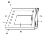
- FIG. 2 shows the polarizing plate pasting apparatus 20.
- the polarizing plate pasting apparatus 20 includes a panel placement unit 21, and a pasting mechanism 22 for pasting the polarizing plate 12 on the panel 11 after cleaning the surface of the panel 11 provided on the panel placement unit 21. (See FIG. 8).
- the polarizing plate pasting apparatus 20 is a semi-automatic polarizing plate pasting in which the polarizing plate 12 is automatically pasted after the panel surface is cleaned manually using a waste cloth W (see FIGS. 5 and 6). Device 20.
- the panel placement unit 21 is provided on the upper surface of the stage 23.
- the panel mounting portion 21 is formed in a rectangular shape, and has a vertical length of about 100 mm and a horizontal size of about 100 mm, for example.
- the stage 23 is formed in the rectangle, for example, about 120 mm in length and about 120 mm in width.
- Panel mounting portion 21 is provided with panel fixing means (not shown) such as suction holes on the outer periphery.
- the panel mounting part 21 and the stage 23 may be formed in shapes other than a rectangle.
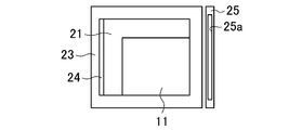
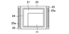
- a suction groove 24 is provided on the outer side of the panel placement portion 21 of the stage 23 along the outer periphery of the panel placement portion so as to surround the outer periphery of the panel placement portion in an annular shape. Further, a solvent supply unit 25 is provided at a position corresponding to one side of the panel mounting unit 21 further outside the suction groove 24.
- the suction groove 24 is formed in a groove shape having a width of about 5 mm and a depth of about 5 mm, for example.
- the suction groove 24 is connected to the intake system 26, and can suck air from the surface of the stage 23 toward the inside of the suction groove 24 with the inside of the suction groove 24 having a negative pressure.
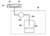
- the intake system 26 includes, for example, a blower pump 26a and a water pallet 26b.
- the air sucked by the blower pump 26a is sent to the water pallet 26b through the pipe 26c.
- the water pallet 26b is provided with a vent 26d.
- the intake system 26 can intake air with a suction force of about 0.02 to 0.05 MPa, for example.
- the intake system 26 may have a configuration other than that shown in FIG.
- the solvent supply unit 25 supplies a certain amount of solvent to the waste W, and can allow the waste W to be impregnated with the solvent.
- the solvent supply unit 25 is, for example, a casing having a length of about 120 mm, a width of about 10 mm, and a height of about 20 mm, and is positioned so that the upper surface is substantially flush with the panel placement unit 21.
- a solvent supply port 25a having an elongated rectangular shape with a length of about 100 mm and a width of about 6 mm is formed, and the solvent is discharged and supplied upward from the solvent supply port 25a.
- the solvent supply unit 25 can discharge a certain amount of solvent by a tube pump or the like.
- the amount of the solvent discharged at one time is, for example, about 2 ⁇ 10 ⁇ 7 m 3 . It is preferable that the solvent supply part 25 can supply a solvent intermittently with the timing according to the cycle for which supply of a solvent is required.
- a pump with programmed solvent discharge timing may be used.
- a foot switch or the like may be attached to the pump, and a certain amount of solvent may be discharged when the operator presses the foot switch.
- the solvent supply part 25 should just be provided further outward of the suction groove 24, may be provided outside the stage 23 as shown in FIG. 23 may be provided integrally. When the solvent supply unit 25 is provided outside the stage 23, the solvent supply unit 25 may be removable from the stage 23.
- the affixing mechanism 22 has the same configuration as the affixing mechanism of the known polarizing plate affixing device 20, and after removing the protective paper from the polarizing plate 12 without manual operation.
- the polarizing plate 12 can be attached to the panel 11 on the panel mounting portion 21.
- the affixing mechanism 22 is provided, for example, so as to be movable relative to the stage 23, and includes a polarizing plate holding part 22a and an affixing roller 22b.
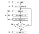
- FIG. 4 shows a flowchart of the attaching process of the polarizing plate 12.
- the polarizing plate pasting apparatus 20 described above is used, and after the panel surface is cleaned manually, the pasting mechanism 22 automatically pastes the polarizing plate 12 onto the panel surface. It is like that.
- step S ⁇ b> 1 the panel 11 is placed on the panel placement unit 21 of the stage 23.
- step S2 foreign matter on the panel surface is removed using a squeegee by a known method.
- the cleaning of the panel surface using a squeegee can be omitted depending on the state of the panel surface.
- step S3 the panel surface is wiped with a cloth W soaked with a solvent to clean it.
- the cleaning process using the waste cloth W includes a solvent supply step S31, a panel surface wiping step S32, and a well screening step S33.
- the waste cloth W for wiping the panel 11 for example, a cloth made of fibers that easily get entangled with foreign matters, such as microfiber knit, non-woven fabric, knitted fabric, and the like, and hardly generate lint can be used.
- the microfiber knit include a commercially available product named “Zabina Minimax” manufactured by KB Seiren.
- the waste cloth W for example, has a length of about 15 cm and a width of about 10 cm, and is folded in three in the vertical direction to a width of about 3 cm, and is used together with a clip or the like as shown in FIG. . Note that, using a jig for setting a wiper configured to insert the grip portion inside a case such as acrylic resin, the waste cloth W may be set on the jig and the panel 11 may be wiped.
- examples of the solvent discharged from the solvent supply unit 25 include isopropyl alcohol (IPA).
- step S32 the waste W soaked with the solvent is slid to the panel mounting portion 21 side, and the panel surface is wiped up.
- step S33 as shown in FIG. 6B, the foreign matter adhering to the waste cloth W is sucked at the upper part of the suction groove 24 on the outer side of the panel wiping end position.
- the foreign matter is sucked in the suction groove 24 and sent to the intake system 26.
- the air containing the foreign matter sucked in by the intake system 26 reaches the water pallet 26b through the pipe 26c, and the foreign matter is caught by the water in the water pallet 26b, while the air from which the foreign matter has been removed enters the water pallet 26b. It exhausts from the provided vent 26d.
- suction grooves 24 provided in an annular shape on the outer periphery of the panel mounting portion, suction is performed as shown in FIG. 7 except for the suction grooves 24a outside the panel wiping end position on the side opposite to the solvent supply portion 25. It is preferable to use the groove 24b with a lid 24c. By covering the portion 24b of the suction groove 24 that is not used for cleaning the waste W with the lid 24c, the power consumption for operating the intake system 26 can be suppressed.
- steps S31 to S33 until there is no foreign matter on the panel surface. For example, the processes of steps S31 to S33 are repeated twice, and in step S4, the state of the panel surface is visually confirmed, and if there is no problem, the process proceeds to the next affixing process. If foreign matter remains that cannot be removed by wiping the panel surface with the waste cloth W, cleaning with a squeegee and wiping with the waste cloth W are repeated as necessary.
- the solvent supply step S31, the panel surface wiping step S32, and the well screening step S33 have been described as wiping the panel surface as one cycle. However, if the panel surface can be wiped with the solvent soaked in the waste W, In addition, depending on the characteristics of the solvent and the properties of the waste W, the solvent supply in the solvent supply step S31 may not be performed every cycle.
- step S5 the attaching mechanism 22 is operated, and the polarizing plate 12 is attached to the panel surface.
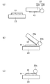
- the stage 23 is moved below the attaching mechanism 22 as shown in FIG. 8 (a)), the polarizing plate 12 held by the polarizing plate holding portion 22a is moved onto the panel 11 while peeling off the protective paper (not shown) (FIG. 8 (b)). Then, the polarizing plate 12 is attached by rotating the attaching roller 22b in contact with the polarizing plate 12 transferred onto the panel 11 (FIG. 8C).
- the polarizing plate 12 is attached to the other surface of the panel 11 as necessary.
- the cleaning of the waste W can be performed only by sliding the waste W in a straight line and holding the waste W over the suction groove 24 without the work of transferring the waste W to the adhesive sheet. Time can be shortened, and a good tact time can be obtained in the polarizing plate attaching step. Furthermore, since the waste W can be cleaned simply by sliding the waste W in a straight line, it is possible to prevent foreign matter adhering to the waste W from falling on the panel surface.
- the polarizing plate attaching apparatus 20 is provided with the solvent supply unit 25 further outside the suction groove 24.
- the solvent supply unit 25 is provided. It doesn't matter. In that case, the solvent may be soaked into the waste W by means other than the solvent supply unit 25 described above (for example, hand wrap). Further, the panel surface may be wiped without causing the waste W to soak the solvent. However, from the viewpoint of the cleaning effect when the panel surface is wiped, it is preferable to wipe the panel surface by soaking the solvent in the cloth W. In addition, it is preferable that a solvent supply unit 25 is provided on the outer side of the suction groove 24 from the viewpoint of shortening an operation time necessary for causing the waste W to soak the solvent.
- the suction groove 24 is provided so as to surround the outer periphery of the panel placement portion in an annular shape.
- the present invention is not limited to this and is provided in at least a part of the outer periphery of the panel placement portion. Also good.
- the suction groove 24 may be provided along only one side of the panel placement portion 21.
- the suction grooves 24 are provided so as to surround the outer periphery of the panel placement portion in an annular shape.
- the solvent supply portion 25 is positioned opposite the suction groove 24 with the panel placement portion 21 interposed therebetween. It is preferable that, in the process of wiping the panel surface, the solvent supply step, the panel surface wiping step, and the well screening step can be performed by moving the waste W in a straight line. Tact time can be obtained.
- the solvent supply unit 25 has been described as being provided at a position corresponding to one side of the panel placement unit 21, but is not limited to this, and the suction groove 24 further extends along the outer periphery of the panel placement unit. It only has to be provided outside.
- the solvent supply unit 25 may be provided along two opposing sides of the outer peripheral edge of the panel placement unit, so that the outer side of the suction groove 24 is annularly surrounded. It may be provided.
- the solvent supply unit 25 When the solvent supply unit 25 is provided along two opposing sides of the outer periphery of the panel placement unit, the solvent supply unit 25 on one end side soaks the solvent into the waste W and then moves from one end side to the other end side. The surface of the panel is wiped, the waste W is cleaned by the suction groove 24 on the other end side, the waste W is slid further outward from the suction groove 24, and the solvent is supplied to the waste W by the solvent supply unit 25 on the other end side. After soaking, the surface of the panel is wiped from the other end side to the one end side, and the waste W can be cleaned by the suction groove 24 on the one end side. That is, since the panel surface can be wiped by reciprocating, the working efficiency is improved.
- the method of attaching the polarizing plate 12 to the liquid crystal display device 10 has been described.
- a polarizing plate is attached to a display device such as an EL) display, a field emission display (FED), or a surface electric field display (SED).
- the polarizing plate was attached using the polarizing plate attaching apparatus of this embodiment.
- the size of the stage of this polarizing plate pasting apparatus was a rectangle with a length of 150 mm in length and width, and a waste having a width of 30 mm was used.
- a polarizing plate was attached using a conventional semi-automatic polarizing plate attaching apparatus using a liquid crystal panel having a side of 3 inches.
- the polarizing plate pasting apparatus 120 used in the comparative example has a configuration in which an adhesive mat 122 having a length of 100 mm and a width of 30 mm is provided on the outer peripheral edge of the panel mounting portion 121. After the surface of the panel 111 was wiped, the waste was cleaned with the adhesive mat 122.
- the amount of foreign matter adhering to the waste was examined at the stage where the waste was cleaned for each of the examples and comparative examples.
- the operation of hitting the waste cloth from the position 30 mm above the panel toward the panel was performed 5 times, and the amount of foreign matter dropped on the panel was visually compared.
- the operation of hitting the cloth is about 0.2 seconds from the position 30 mm above the panel to reach the panel, and about 0.5 seconds in one round trip until it returns to the position 30 mm above the panel. It was. Then, when the state of the panel surface was observed visually, it turned out that more foreign materials have fallen on the panel of the comparative example than the Example.
- the present invention is useful for a polarizing plate attaching apparatus for attaching a polarizing plate to a liquid crystal panel or the like, and a polarizing plate attaching method using the same.
- Liquid crystal display device 11 Liquid crystal panel (panel) DESCRIPTION OF SYMBOLS 12 Polarizing plate 20 Polarizing plate sticking apparatus 21 Panel mounting part 23 Stage 24 Suction groove 25 Solvent supply part
Landscapes
- Physics & Mathematics (AREA)
- Nonlinear Science (AREA)
- Mathematical Physics (AREA)
- Chemical & Material Sciences (AREA)
- Crystallography & Structural Chemistry (AREA)
- General Physics & Mathematics (AREA)
- Optics & Photonics (AREA)
- Liquid Crystal (AREA)
Abstract
ステージ(23)のパネル載置部(21)外側方にパネル載置部(21)外周縁の少なくとも一部に沿うように設けられた吸引溝(24)と、吸引溝(24)に接続され吸引溝(24)内部を負圧にしてステージ(23)の表面から吸引溝(24)内部に向かって空気を吸気する吸気システムとを備え、パネル載置部(21)に載置されて清浄処置が施されたパネル(11)に偏光板(12)を貼り付ける。
Description
本発明は、液晶パネル等に偏光板を貼り付ける偏光板貼り付け装置、及びそれを用いた偏光板貼り付け方法に関する。
液晶表示装置は、薄型化が可能で低消費電力であるため、パーソナルコンピュータ等のOA機器や携帯電話、PDA(Personal Digital Assistant)等の携帯情報機器のディスプレイとして広く用いられている。
液晶表示装置は、液晶パネルの両表面に偏光板が貼り付けられており、その背面側にはバックライトユニットが設けられている。液晶表示装置に偏光板が貼設されていることにより、液晶パネルを透過する光や液晶パネルから出射された光の振動方向を一方向に制限できるので、優れた輝度特性を得ることができる。
偏光板は、まず、パネル表面の洗浄を行った後、偏光板から保護紙を剥離してパネル表面に貼り付ける。
偏光板貼り付けプロセスにおいては、液晶パネルと偏光板との間に異物が挟まると、偏光板が撓んだり、液晶パネルと偏光板との間に気泡が入ったりして、液晶表示装置の表示特性上、基点不良やムラ不良等の問題が生じる。そのため、偏光板貼り付けプロセスにおいては、パネル表面の洗浄性能の向上により異物をより効率よく除去することが要求されている。
ところで、偏光板貼り付け装置としては、全自動偏光板貼り付け装置や半自動偏光板貼り付け装置が挙げられる。全自動偏光板貼り付け装置は、偏光板貼り付けステージへの液晶パネルの供給及び排出、偏光板の取り出し、保護紙の剥離、液晶パネルへの偏光板の貼り付け等、偏光板貼り付けに関する工程を全て自動で行う装置である。一方、半自動偏光板貼り付け装置は、偏光板貼り付けステージへの液晶パネルの供給及び排出、偏光板の取り出し、保護紙の剥離等の工程を手作業で行い、液晶パネルへの偏光板の貼り付けのみを自動で行う装置である。
全自動偏光板貼り付け装置によれば、全ての偏光板貼り付け作業を無人で行うことができるので、液晶パネルと偏光板との間に異物が挟まるのを有効に抑制することができる。しかしながら、全自動偏光板貼り付け装置は価格が非常に高く(半自動偏光板貼り付け装置の約20倍程度)、安価な半自動偏光板貼り付け装置を用いて効率よくパネル表面の清浄作業を行うことが望まれる。
半自動偏光板貼り付け装置を用いた偏光板の貼り付けプロセスにおいては、パネル表面の清浄を、例えば、まず、スキージを用いて付着ゴミを除去した後、不織布やニット等の布(ウェス)を用いて油や指紋等の汚れを拭きとることにより行っている。例えば、特許文献1には、エタノールをしみ込ませたウェスによって液晶パネルの偏光板貼り付け面を拭くことが記載されている。
しかしながら、溶剤等をしみ込ませたウェスを用いてパネル表面を拭いても、除去した埃等がパネル表面に落ちて再付着したり、ウェス自身から発生する糸くず等の塵がパネル表面に付着したりする問題があり、異物の除去が十分とはいえない。
そのため、現在、ウェスでパネル表面を拭いた後にウェスを粘着テープに転写して、ウェスで拭き取った異物やウェスからの発塵をウェスから取り除くことによりウェス自身をクリーニングしながら清浄作業を行うことが行われている。
しかしながら、ウェスに付着した塵埃を粘着テープに転写しながら液晶パネルの清浄を行う方法では、塵埃を粘着テープに転写するための手間がかかり、作業時間をロスしてしまう問題がある。その上、依然として、塵埃を粘着テープに転写するまでの間に異物がパネル表面に落ちて付着する問題は解決されない。
本発明は、パネルと偏光板との間に異物が挟まるのを抑制すると共に良好なタクトタイムを得ながらパネルに偏光板の貼り付けを行うことや、それに用いる偏光板貼り付け装置を提供することを目的とする。
本発明の偏光板貼り付け装置は、上面にパネル載置部が設けられたステージを備え、パネル載置部に載置されて清浄処置が施されたパネルに偏光板を貼り付けるものであって、ステージのパネル載置部外側方にパネル載置部外周縁の少なくとも一部に沿うように設けられた吸引溝と、吸引溝に接続され吸引溝内部を負圧にしてステージの表面から吸引溝内部に向かって空気を吸気する吸気システムと、を備えたことを特徴とする。
上記の偏光板貼り付け装置によれば、パネル載置部にパネルを載置した状態でパネル表面を拭いたウェスを拭き作業の直後に吸引溝上にかざすことにより、ウェスに付着した塵埃やウェスの繊維屑等の異物を吸気システムに接続された吸引溝に吸引してウェスをクリーニングすることができる。そのため、吸引された異物が再びウェスに付着してしまうことがなく、効率よくウェスのクリーニングを行うことができる。また、吸引溝がパネル載置部外側方にパネル載置部外周縁に沿って設けられているので、パネル表面を拭いたウェスをそのまま一直線にパネル載置部外側方にスライドさせて、拭き作業とウェスのクリーニング作業とを連続して行うことができる。そのため、クリーニング作業のためにかかる時間を短縮できることに加えて、ウェスをクリーニングのために移動させる過程でウェスに付着した異物がパネル上に落ちるのを防止することができる。したがって、良好なタクトタイムが得られると共に、パネルと偏光板との間に異物が挟まるのが抑制されて良好な歩留まりが得られる。
本発明の偏光板貼り付け装置は、パネル載置部を挟んで吸引溝と対向する位置のステージ外周縁部に溶剤供給部が設けられていることが好ましい。
上記の偏光板貼り付け装置によれば、パネル載置部を挟んで吸引溝と対向する位置に溶剤供給部が設けられているので、溶剤供給部からパネル載置部上のパネルを通って吸引溝まで一直線にウェスを移動させることができる。従って、効率よくウェスに溶剤をしみ込ませた後にパネルを拭くことができ、偏光板貼り付け工程のパネル清浄において、良好なタクトタイムが得られる。
本発明の偏光板貼り付け装置は、吸引溝が、ステージのパネル載置部外周縁を環状に囲うように設けられていることが好ましい。
上記の偏光板貼り付け装置によれば、吸引溝が、ステージのパネル載置部外周縁を環状に囲うように設けられているので、どの方向からパネル表面を拭いても拭き終わり位置の外側方に吸引溝が存在してウェスのクリーニングを行うことができる。そのため、例えばウェスで拭く方向により特性があるような複数のモデルのパネルに対しても、この偏光板貼り付け装置を使用することができる。
本発明の偏光板貼り付け装置は、ステージが矩形に形成され、吸引溝が、ステージのパネル載置部外周縁の少なくとも対向する2辺に沿うように設けられ、溶剤供給部が、吸引溝の対向する2辺のそれぞれの外側方に設けられていてもよい。
上記の偏光板貼り付け装置によれば、吸引溝、溶剤供給部が共にパネル載置部外周縁の少なくとも対向する2辺に沿うように設けられているので、一端側の溶剤供給部からパネル上を通って他端側の吸引溝まで一直線に移動させた後、そのまま、他端側の溶剤供給部でウェスに溶剤をしみ込ませて、再びパネル上を通って一端側の吸引溝まで一直線に移動させることができる。つまり、パネル上を往復させながらパネル表面を拭くことができるので、偏光板貼り付け工程のパネル清浄において、良好なタクトタイムが得られる。
本発明の偏光板貼り付け装置は、パネルが液晶パネルであってもよい。
本発明の偏光板貼り付け方法は、上面にパネル載置部が設けられたステージと、ステージのパネル載置部外側方にパネル載置部外周縁の少なくとも一端側に沿うように設けられた吸引溝と、吸引溝に接続され吸引溝内部を負圧にしてステージの表面から吸引溝内部に向かって空気を吸気する吸気システムと、を備えた偏光板貼り付け装置を用意し、パネル載置部にパネルを載置した状態でウェスでパネル表面を他端側から一端側に向かって拭いた後、パネルの一端側に設けられた吸引溝でウェスの表面に付着した異物を吸引して該ウェスをクリーニングする工程を必要に応じて繰り返すことによりパネル表面の清浄を行い、次いで、パネル表面に偏光板を貼り付けることを特徴とする。
上記の偏光板貼り付け方法によれば、吸引溝でウェスの表面に付着した異物を吸引して該ウェスをクリーニングするので、パネル載置部にパネルを載置した状態でパネル表面を拭いたウェスを拭き作業の直後に吸引溝上にかざすことにより、ウェスに付着した塵埃やウェスの繊維屑等の異物を吸気システムに接続された吸引溝に吸引してウェスをクリーニングすることができる。そのため、吸引された異物が再びウェスに付着してしまうことがなく、効率よくウェスのクリーニングを行うことができる。また、パネル載置部にパネルを載置した状態でウェスでパネル表面を他端側から一端側に向かって拭いた後、ウェスをクリーニングするための吸引溝がパネルの一端側に設けられているので、ウェスをそのまま一直線にパネル載置部外側方にスライドさせて、拭き作業とウェスのクリーニング作業とを連続して行うことができる。そのため、クリーニング作業のためにかかる時間を短縮できることに加えて、ウェスをクリーニングのために移動させる過程でウェスに付着した異物がパネル上に落ちるのを防止することができる。したがって、良好なタクトタイムが得られると共に、パネルと偏光板との間に異物が挟まるのが抑制されて良好な歩留まりが得られる。
本発明の偏光板貼り付け方法は、偏光板貼り付け装置において、パネル載置部を挟んで吸引溝と対向する他端側のステージ外周縁部に溶剤供給部が設けられ、パネル表面の清浄を行う際、ウェスに他端側の溶剤供給部から供給される溶剤をしみ込ませた状態でパネル表面を拭く作業を行うことが好ましい。
この場合、パネル載置部にパネルを載置した状態で他端側の溶剤供給部から供給される溶剤をウェスにしみ込ませ、ウェスでパネル表面を他端側から一端側に向かって拭いた後、パネルの一端側に設けられた吸引溝でウェスの表面に付着した異物を吸引してウェスをクリーニングする工程を1サイクルとして、当該サイクルを必要に応じて繰り返すことにより、パネル表面の清浄を行ってもよい。
上記の偏光板貼り付け方法によれば、パネル載置部を挟んで吸引溝と対向する位置に溶剤供給部が設けられているので、溶剤供給部からパネル載置部上のパネルを通って吸引溝まで一直線にウェスを移動させることにより、ウェスへの溶剤のしみ込ませ作業、拭き作業、及びウェスのクリーニング作業を連続して行うことができる。従って、効率よくウェスに溶剤をしみ込ませた後にパネルを拭くことができ、良好なタクトタイムが得られる。
本発明の偏光板貼り付け方法は、偏光板貼り付け装置において、吸引溝が、ステージのパネル載置部外周縁を環状に囲うように設けられていることが好ましい。
本発明の偏光板貼り付け方法は、偏光板貼り付け装置において、ステージが矩形に形成され、吸引溝が、ステージのパネル載置部外周縁の少なくとも対向する2辺に沿うように設けられ、溶剤供給部が、吸引溝の対向する2辺のそれぞれの外側方に設けられており、パネル表面の清浄を、パネル載置部にパネルを載置した状態でウェスでパネル表面を他端側から一端側に向かって拭いた後、該パネルの上記一端側に設けられた吸引溝で該ウェスの表面に付着した異物を吸引して該ウェスをクリーニングし、続いて、該ウェスでパネル表面を一端側から他端側に向かって拭いた後、該パネルの他端側に設けられた吸引溝でウェスの表面に付着した異物を吸引してウェスをクリーニングする工程を必要に応じて繰り返すことにより行ってもよい。
本発明の偏光板貼り付け方法は、ウェスが、マイクロファイバーのニットで構成されていてもよい。
本発明の偏光板貼り付け方法は、溶剤がイソプロピルアルコールであることが好ましい。
本発明の偏光板貼り付け方法は、パネルが液晶パネルであってもよい。
本発明によれば、パネル載置部にパネルを載置した状態でパネル表面を拭いたウェスを拭き作業の直後に吸引溝上にかざすことにより、ウェスに付着した塵埃やウェスの繊維屑等の異物を吸気システムに接続された吸引溝に吸引してウェスをクリーニングすることができる。そのため、吸引された異物が再びウェスに付着してしまうことがなく、効率よくウェスのクリーニングを行うことができる。また、吸引溝がパネル載置部外側方にパネル載置部外周縁に沿って設けられているので、パネル表面を拭いたウェスをそのまま一直線にパネル載置部外側方にスライドさせて、拭き作業とウェスのクリーニング作業とを連続して行うことができる。そのため、クリーニング作業のためにかかる時間を短縮できることに加えて、ウェスをクリーニングのために移動させる過程でウェスに付着した異物がパネル上に落ちるのを防止することができる。したがって、偏光板貼り付け時に良好なタクトタイムが得られると共に、パネルと偏光板との間に異物が挟まるのが抑制されて良好な歩留まりが得られる。
以下、本発明の実施形態を図面に基づいて詳細に説明する。本実施形態では、液晶表示装置に偏光板を貼り付けるための偏光板貼り付け装置やその方法について説明する。但し、本発明は本実施形態に限定されるものではなく、他の構成であってもよい。
液晶表示装置10は、図1に示すように、液晶パネル11の両表面に偏光板12が貼り付けられており、その背面側にはバックライトユニット13が設けられている。液晶表示装置10に偏光板12が貼設されていることにより、液晶パネル11を透過する光や液晶パネル11から出射された光の振動方向を一方向に制限できるので、優れた輝度特性を得ることができる。
図2は、偏光板貼り付け装置20を示す。偏光板貼り付け装置20は、パネル載置部21を備え、パネル載置部21上に設けられたパネル11の表面に清浄処置を施した後にパネル11に偏光板12を貼り付ける貼り付け機構22(図8参照)を備えている。なお、この偏光板貼り付け装置20は、ウェスW(図5及び6参照)を用いた手作業でパネル表面の清浄処置を行った後に偏光板12の貼り付けを自動で行う半自動偏光板貼り付け装置20である。
パネル載置部21は、ステージ23の上面に設けられている。パネル載置部21は矩形に形成されており、例えば縦が100mm程度及び横が100mm程度である。また、ステージ23は矩形に形成されており、例えば縦が120mm程度及び横が120mm程度である。パネル載置部21には、外周に吸着穴等のパネル固定手段(不図示)が設けられている。なお、パネル載置部21やステージ23は矩形以外の形状に形成されていてもよい。
ステージ23のパネル載置部21外側方には、パネル載置部外周縁に沿って、パネル載置部外周縁を環状に囲うように吸引溝24が設けられている。そして、吸引溝24のさらに外方には、パネル載置部21の一辺に対応する位置に溶剤供給部25が設けられている。
吸引溝24は、例えば幅が5mm程度及び深さが5mm程度の溝状に形成されている。吸引溝24は、吸気システム26に接続されており、吸引溝24の内部を負圧にしてステージ23の表面から吸引溝24の内部に向かって空気を吸気することができる。
吸気システム26は、図3に示すように、例えば、ブロアポンプ26aとウォーターパレット26bとを備えている。この場合、ブロアポンプ26aで吸気された空気は、配管26cを通ってウォーターパレット26bにまで送られる。また、ウォーターパレット26bには、通気口26dが設けられている。吸気システム26は、例えば0.02~0.05MPa程度の吸引力で空気を吸気することができる。なお、吸気システム26は図3に示した以外の構成であってもよい。
溶剤供給部25は、一定量の溶剤をウェスWに供給するものであり、ウェスWに溶剤をしみ込ませることができる。溶剤供給部25は、例えば、縦が120mm程度、横が10mm程度、及び高さが20mm程度の筐体であり、上面がパネル載置部21と略同一平面となるように位置づけられている。溶剤供給部25の上面には、例えば縦が100mm程度及び横が6mm程度の細長矩形に開口した溶剤供給口25aが形成されており、溶剤供給口25aから上方に溶剤が吐出して供給される。
溶剤供給部25は、チューブポンプ等により一定量の溶剤を吐出することができる。1回で吐出される溶剤の量は、例えば、2×10⁻⁷m3程度である。溶剤供給部25は、溶剤の供給が必要とされるサイクルに合わせたタイミングで断続的に溶剤を供給可能であることが好ましい。断続的に溶剤の供給を行うために、溶剤吐出のタイミングをプログラムしたポンプを用いてもよい。また、ポンプにフットスイッチなどを取り付けて、作業者がフットスイッチを押したタイミングで一定量の溶剤が吐出されるように構成してもよい。
なお、溶剤供給部25は、吸引溝24のさらに外方に設けられていればよく、図2に示すようにステージ23の外部に設けられていてもよく、さらには、ステージ23の上にステージ23と一体に設けられていてもよい。溶剤供給部25がステージ23の外部に設けられている場合、溶剤供給部25はステージ23から取り外し可能であってもよい。
貼り付け機構22は、図8に示すように、公知の偏光板貼り付け装置20の貼り付け機構と同様の構成を有し、手作業によらないで、偏光板12から保護紙を剥離した後、パネル載置部21上のパネル11に偏光板12を貼り付けることができる。貼り付け機構22は、例えば、ステージ23と相対移動可能に設けられており、偏光板保持部22aと貼り付けローラー22bとを備える。
図4は、偏光板12の貼り付け工程のフローチャートを示す。この偏光板貼り付け工程は、上記説明した偏光板貼り付け装置20を用い、手作業によりパネル表面の清浄処置を行った後に貼り付け機構22によって自動でパネル表面に偏光板12の貼り付けを行うようになっている。
初めに、ステップS1において、パネル11をステージ23のパネル載置部21上に載置する。
次に、ステップS2において、公知の方法により、スキージを用いてパネル表面の異物の除去を行う。なお、スキージを用いたパネル表面の清掃は、パネル表面の状態に応じて省略可能である。
続いて、ステップS3において、溶剤をしみ込ませたウェスWでパネル表面を拭いて清浄する。このステップでは、スキージでは除去できなかった異物やパネル表面の指紋等の汚れの清浄を行う。ウェスWによる清浄工程は、溶剤供給ステップS31、パネル表面拭き上げステップS32、及びウェスクリーニングステップS33を備えている。
なお、パネル11を拭くウェスWとしては、例えば、マイクロファイバーのニットや、不織布、編布等、異物を絡ませやすく糸屑の出にくい繊維からなるクロスを用いることができる。マイクロファイバーのニットとしては、例えば、KBセーレン社製の商標名「ザビーナミニマックス」なる市販品などが挙げられる。ウェスWは、例えば、縦が15cm程度及び横が10cm程度であり、これを、縦方向に3つ折りして3cm程度の幅にしたものを、図5に示すようにクリップ等でまとめて使用する。なお、アクリル樹脂などのケースの内部にグリップ部を挿入する構成のワイパーをセットするための治具を用いて、この治具にウェスWをセットしてパネル11を拭いてもよい。
まず、ウェスWを手でつかんだ後、ステップS31において、図6(a)に示すように溶剤供給口25aにウェスWをかざして、ウェスWに溶剤をしみ込ませる。このとき、溶剤供給部25から吐出される溶剤としては、例えばイソプロピルアルコール(IPA)等が挙げられる。
次に、ステップS32において、溶剤がしみ込んだウェスWをパネル載置部21側にスライドさせ、パネル表面を拭き上げる。
続いて、そのまま一直線にウェスWを移動させ、ステップS33において、図6(b)に示すように、パネル拭き終わり位置の外側方の吸引溝24の上部でウェスWに付着した異物を吸引させる。このとき、異物は吸引溝24で吸引され、吸気システム26に送られる。吸気システム26で吸気された異物を含む空気は、配管26cを通ってウォーターパレット26bに到達し、異物はウォーターパレット26b内の水でキャッチされる一方、異物が除かれた空気はウォーターパレット26bに設けられた通気口26dから排気される。
なお、パネル載置部外周縁に環状に設けられた吸引溝24のうち、溶剤供給部25とは反対側のパネル拭き終わり位置の外側方の吸引溝24a以外は、図7に示すように吸引溝24bに蓋24cをして使用することが好ましい。吸引溝24のうち、ウェスWのクリーニングのために使用されない部分24bに蓋24cをすることにより、吸気システム26稼動のための電力消費量を抑制することができる。
パネル表面の異物がなくなるまでステップS31~S33の工程を繰り返す。例えば、ステップS31~S33の工程を2回繰り返し、ステップS4において、目視によりパネル表面の状態を確認して問題がなければ、次の貼り付け工程に移る。なお、ウェスWでパネル表面を拭いても除去できない異物が残っている場合には、必要に応じてスキージによる清掃及びウェスWによる拭き上げを繰り返し行う。
なお、溶剤供給ステップS31、パネル表面拭き上げステップS32、及びウェスクリーニングステップS33を1サイクルとして繰り返してパネル表面を拭くとして説明したが、ウェスWに溶剤がしみ込んだ状態でパネル表面を拭くことができればよく、溶剤の特性やウェスWの性質によっては、溶剤供給ステップS31における溶剤供給を毎サイクル行わなくてもよい。
パネル表面の清浄処置が終わると、作業者は、貼り付け機構22を作動させるスイッチを入れる。これにより、ステップS5において貼り付け機構22が作動し、パネル表面への偏光板12の貼り付けが行われる。
例えば、貼り付け機構22が偏光板保持部22aと貼り付けローラー22bとを備えた構成である場合には、図8に示すように、ステージ23を貼り付け機構22の下に移動させた後(図8(a))、偏光板保持部22aで保持された偏光板12を、保護紙(不図示)を剥離しながらパネル11上に移す(図8(b))。そして、パネル11上に移った偏光板12に貼り付けローラー22bを当接させながら回転させることにより、偏光板12の貼り付けを行う(図8(c))。
パネル11の一方の表面への偏光板12の貼り付けが完了すると、必要に応じて、パネル11の他方の表面にも偏光板12の貼り付けを行う。
<本実施形態の効果>
上記の構成の偏光板貼り付け装置20を用いた偏光板貼り付け方法によれば、吸引溝24によりウェスWのクリーニングを行うので、吸引溝24で吸引された異物が吸気システム26に送られるため、一旦ウェスWから取り除いた異物が再びウェスWに付着してしまうことがない。
上記の構成の偏光板貼り付け装置20を用いた偏光板貼り付け方法によれば、吸引溝24によりウェスWのクリーニングを行うので、吸引溝24で吸引された異物が吸気システム26に送られるため、一旦ウェスWから取り除いた異物が再びウェスWに付着してしまうことがない。
また、ウェスWのクリーニングを、ウェスWを粘着シートに転写させる作業を伴わないで、ウェスWを一直線にスライドさせてウェスWを吸引溝24の上方にかざすことによってのみ行うことができるので、作業時間を短縮することかでき、偏光板貼り付け工程において良好なタクトタイムが得られる。さらに、一直線にウェスWをスライドさせるだけでウェスWのクリーニングを行うことができるので、ウェスWに付着した異物がパネル表面に落ちるのが抑制される。
なお、本実施形態では偏光板貼り付け装置20は吸引溝24のさらに外方に溶剤供給部25が設けられているとして説明したが、図9に示すように、溶剤供給部25が設けられていなくても構わない。その場合には、上記説明した溶剤供給部25以外の手段(例えば、ハンドラップ等)によってウェスWに溶剤をしみ込ませてもよい。また、ウェスWに溶剤をしみ込ませることなくパネル表面を拭いてもよい。但し、パネル表面を拭いたときの清浄効果の点からはウェスWに溶剤をしみ込ませてパネル表面を拭くことが好ましい。また、ウェスWに溶剤をしみ込ませるのに必要な作業時間を短縮する点から、吸引溝24のさらに外方に溶剤供給部25が設けられていることが好ましい。
本実施形態では吸引溝24がパネル載置部外周縁を環状に囲うように設けられているとして説明したが、特にこれに限られず、パネル載置部外周縁の少なくとも一部に設けられていてもよい。例えば、吸引溝24がパネル載置部21の一辺にのみ沿うように設けられていてもよい。但し、パネル拭き方向に関係なく複数のモデルのパネルに対応可能にする観点からは、吸引溝24がパネル載置部外周縁を環状に囲うように設けられていることが好ましい。
図10に示すように、吸引溝24がパネル載置部21の一辺にのみ沿うように設けられている場合、溶剤供給部25は、パネル載置部21を挟んで吸引溝24と対向する位置に設けられていることが好ましく、これにより、パネル表面を拭く工程において、溶剤供給ステップ、パネル表面拭き上げステップ、及びウェスクリーニングステップを、ウェスWを一直線に移動させることにより行うことができ、良好なタクトタイムが得られる。
本実施形態では溶剤供給部25がパネル載置部21の一辺に対応する位置に設けられているとして説明したが、特にこれに限られず、パネル載置部外周縁に沿って吸引溝24のさらに外方に設けられていればよい。例えば、溶剤供給部25は、図11に示すように、パネル載置部外周縁の対向する2辺に沿うように設けられていてもよく、吸引溝24のさらに外方を環状に囲うように設けられていてもよい。
溶剤供給部25がパネル載置部外周縁の対向する2辺に沿うように設けられている場合、一端側の溶剤供給部25でウェスWに溶剤をしみ込ませた後に一端側から他端側に向かってパネル表面を拭いて他端側の吸引溝24でウェスWのクリーニングを行い、そのままウェスWを吸引溝24からさらに外側方にスライドさせて他端側の溶剤供給部25でウェスWに溶剤をしみ込ませた後に他端側から一端側に向かってパネル表面を拭いて一端側の吸引溝24でウェスWのクリーニングを行うことができる。つまり、パネル表面を往復させるようにして拭くことができるので、作業効率が向上する。
本実施形態では、液晶表示装置10に偏光板12を貼り付ける方法について説明したが、プラズマディスプレイ(PD)、プラズマアドレス液晶ディスプレイ(PALC)、有機エレクトロルミネッセンス(有機EL)ディスプレイ、無機エレクトロルミネッセンス(無機EL)ディスプレイ、電界放出ディスプレイ(FED)、表面電界ディスプレイ(SED)などの表示装置に偏光板を貼り付ける場合にも適用することができる。
一辺が3インチの液晶パネルについて、本実施形態の偏光板貼り付け装置を用いて偏光板の貼り付けを行った。この偏光板貼り付け装置のステージの大きさは縦及び横の長さが150mmの矩形であり、30mm幅のウェスを使用した。また、比較例として、同じく一辺が3インチの液晶パネルを用いて、従来の半自動の偏光板貼り付け装置を用いて偏光板の貼り付けを行った。比較例で用いた偏光板貼り付け装置120は、図12に示すように、パネル載置部121の外周縁に縦が100mm及び横が30mmの粘着マット122が設けられた構成のものであり、パネル111の表面を拭いた後に粘着マット122でウェスのクリーニングを行った。
パネルを拭くための作業時間を比較すると、ウェスをつかんでから溶剤をしみ込ませてパネルを拭き、ウェスを離すまでの時間(清掃タクト)が、比較例では8秒であったのに対して実施例は4秒に短縮することができた。
また、パネル表面を1回拭いた後、実施例、比較例それぞれについてウェスのクリーニングを行った段階で、ウェスに付着している異物の量を調べた。ウェスをパネルの上方30mmの位置からパネルに向かってたたきつける動作を5往復行って、パネル上に落ちた異物の量を目視で比較した。なお、ウェスをたたきつける動作は、パネルの上方30mmの位置からパネルに到達するまでに約0.2秒、パネルの上方30mmの位置に戻ってくるまでの1往復で約0.5秒かけて行った。その後、パネル表面の様子を目視により観察すると、比較例のパネル上には実施例よりも多くの異物が落ちていることが分かった。
さらに、偏光板貼り付け工程における不良率を比較すると、1.0%から0.5%に低減した。
本発明は、液晶パネル等に偏光板を貼り付ける偏光板貼り付け装置、及びそれを用いた偏光板貼り付け方法について有用である。
10 液晶表示装置
11 液晶パネル(パネル)
12 偏光板
20 偏光板貼り付け装置
21 パネル載置部
23 ステージ
24 吸引溝
25 溶剤供給部
11 液晶パネル(パネル)
12 偏光板
20 偏光板貼り付け装置
21 パネル載置部
23 ステージ
24 吸引溝
25 溶剤供給部
Claims (13)
- 上面にパネル載置部が設けられたステージを備え、該パネル載置部に載置されて清浄処置が施されたパネルに偏光板を貼り付ける偏光板貼り付け装置であって、
上記ステージのパネル載置部外側方に該パネル載置部外周縁の少なくとも一部に沿うように設けられた吸引溝と、
上記吸引溝に接続され該吸引溝内部を負圧にして上記ステージの表面から上記吸引溝内部に向かって空気を吸気する吸気システムと、
を備えたことを特徴とする偏光板貼り付け装置。 - 請求項1に記載された偏光板貼り付け装置において、
上記パネル載置部を挟んで上記吸引溝と対向する位置のステージ外周縁部に溶剤供給部が設けられていることを特徴とする偏光板貼り付け装置。 - 請求項1または2に記載された偏光板貼り付け装置において、
上記吸引溝は、上記ステージのパネル載置部外周縁を環状に囲うように設けられていることを特徴とする偏光板貼り付け装置。 - 請求項2に記載された偏光板貼り付け装置において、
上記ステージは、矩形に形成され、
上記吸引溝は、上記ステージのパネル載置部外周縁の少なくとも対向する2辺に沿うように設けられ、
上記溶剤供給部は、上記吸引溝の対向する2辺のそれぞれの外側方に設けられていることを特徴とする偏光板貼り付け装置。 - 請求項1~4のいずれかに記載された偏光板貼り付け装置において、
上記パネルは液晶パネルであることを特徴とする偏光板貼り付け装置。 - 上面にパネル載置部が設けられたステージと、
上記ステージのパネル載置部外側方に該パネル載置部外周縁の少なくとも一端側に沿うように設けられた吸引溝と、
上記吸引溝に接続され該吸引溝内部を負圧にして上記ステージの表面から上記吸引溝内部に向かって空気を吸気する吸気システムと、
を備えた偏光板貼り付け装置を用意し、
上記パネル載置部にパネルを載置した状態でウェスでパネル表面を他端側から一端側に向かって拭いた後、該パネルの上記一端側に設けられた吸引溝で該ウェスの表面に付着した異物を吸引して該ウェスをクリーニングする工程を必要に応じて繰り返すことによりパネル表面の清浄を行い、
次いで、上記パネル表面に偏光板を貼り付けることを特徴とする偏光板貼り付け方法。 - 請求項6に記載された偏光板貼り付け方法において、
上記偏光板貼り付け装置は、上記パネル載置部を挟んで上記吸引溝と対向する位置のステージ外周縁部に溶剤供給部が設けられ、
上記パネル表面の清浄を行う際、上記ウェスに上記他端側の溶剤供給部から供給される溶剤をしみ込ませた状態で該パネル表面を拭く作業を行うことを特徴とする偏光板貼り付け方法。 - 請求項7に記載された偏光板貼り付け方法において、
上記パネル載置部にパネルを載置した状態で上記他端側の溶剤供給部から吐出される溶剤をウェスにしみ込ませ、該ウェスでパネル表面を他端側から一端側に向かって拭いた後、該パネルの上記一端側に設けられた吸引溝で該ウェスの表面に付着した異物を吸引して該ウェスをクリーニングする工程を1サイクルとして、当該サイクルを必要に応じて繰り返すことにより、上記パネル表面の清浄を行うことを特徴とする偏光板貼り付け方法。 - 請求項6~8のいずれかに記載された偏光板貼り付け方法において、
上記偏光板貼り付け装置は、上記吸引溝が、上記ステージのパネル載置部外周縁を環状に囲うように設けられていることを特徴とする偏光板貼り付け方法。 - 請求項7または8のいずれかに記載された偏光板貼り付け方法において、
上記偏光板貼り付け装置は、上記ステージが矩形に形成され、上記吸引溝が、上記ステージのパネル載置部外周縁の少なくとも対向する2辺に沿うように設けられ、上記溶剤供給部が、上記吸引溝の対向する2辺のそれぞれの外側方に設けられており、
上記パネル表面の清浄を、上記パネル載置部にパネルを載置した状態でウェスでパネル表面を他端側から一端側に向かって拭いた後、該パネルの上記一端側に設けられた吸引溝で該ウェスの表面に付着した異物を吸引して該ウェスをクリーニングし、続いて、該ウェスでパネル表面を一端側から他端側に向かって拭いた後、該パネルの上記他端側に設けられた吸引溝で該ウェスの表面に付着した異物を吸引して該ウェスをクリーニングする工程を必要に応じて繰り返すことにより行うことを特徴とする偏光板貼り付け方法。 - 請求項6~10のいずれかに記載された偏光板貼り付け方法において、
上記ウェスは、マイクロファイバーのニットで構成されていることを特徴とする偏光板貼り付け方法。 - 請求項7、8及び10のいずれかに記載された偏光板貼り付け方法において、
上記溶剤はイソプロピルアルコールであることを特徴とする偏光板貼り付け方法。 - 請求項6~12のいずれかに記載された偏光板貼り付け方法において、
上記パネルは液晶パネルであることを特徴とする偏光板貼り付け方法。
Applications Claiming Priority (2)
| Application Number | Priority Date | Filing Date | Title |
|---|---|---|---|
| JP2010-088718 | 2010-04-07 | ||
| JP2010088718 | 2010-04-07 |
Publications (1)
| Publication Number | Publication Date |
|---|---|
| WO2011125302A1 true WO2011125302A1 (ja) | 2011-10-13 |
Family
ID=44762273
Family Applications (1)
| Application Number | Title | Priority Date | Filing Date |
|---|---|---|---|
| PCT/JP2011/001787 Ceased WO2011125302A1 (ja) | 2010-04-07 | 2011-03-25 | 偏光板貼り付け装置及び偏光板貼り付け方法 |
Country Status (1)
| Country | Link |
|---|---|
| WO (1) | WO2011125302A1 (ja) |
Cited By (1)
| Publication number | Priority date | Publication date | Assignee | Title |
|---|---|---|---|---|
| CN118151426A (zh) * | 2024-05-09 | 2024-06-07 | 金之鼎(四川)智能科技有限公司 | 一种液晶显示屏生产用面板贴合装置 |
Citations (4)
| Publication number | Priority date | Publication date | Assignee | Title |
|---|---|---|---|---|
| JPH07218882A (ja) * | 1994-01-28 | 1995-08-18 | Sony Corp | 液晶パネル表面クリーニング装置 |
| JP2000176388A (ja) * | 1998-12-21 | 2000-06-27 | Sharp Corp | 液晶表示パネルの洗浄方法および液晶表示パネル洗浄装置 |
| JP2003066456A (ja) * | 2001-08-29 | 2003-03-05 | Seiko Epson Corp | 液晶装置の製造方法および製造装置 |
| JP2003340343A (ja) * | 2002-05-24 | 2003-12-02 | Dainippon Screen Mfg Co Ltd | 基板処理装置 |
-
2011
- 2011-03-25 WO PCT/JP2011/001787 patent/WO2011125302A1/ja not_active Ceased
Patent Citations (4)
| Publication number | Priority date | Publication date | Assignee | Title |
|---|---|---|---|---|
| JPH07218882A (ja) * | 1994-01-28 | 1995-08-18 | Sony Corp | 液晶パネル表面クリーニング装置 |
| JP2000176388A (ja) * | 1998-12-21 | 2000-06-27 | Sharp Corp | 液晶表示パネルの洗浄方法および液晶表示パネル洗浄装置 |
| JP2003066456A (ja) * | 2001-08-29 | 2003-03-05 | Seiko Epson Corp | 液晶装置の製造方法および製造装置 |
| JP2003340343A (ja) * | 2002-05-24 | 2003-12-02 | Dainippon Screen Mfg Co Ltd | 基板処理装置 |
Cited By (1)
| Publication number | Priority date | Publication date | Assignee | Title |
|---|---|---|---|---|
| CN118151426A (zh) * | 2024-05-09 | 2024-06-07 | 金之鼎(四川)智能科技有限公司 | 一种液晶显示屏生产用面板贴合装置 |
Similar Documents
| Publication | Publication Date | Title |
|---|---|---|
| JP4089058B2 (ja) | 印刷用スクリーンの清掃装置及び清掃方法 | |
| CN104959333B (zh) | 液晶显示器偏光板表面除胶清洗装置 | |
| CN206913918U (zh) | 一种数码喷墨印刷机多喷头用清洗装置 | |
| CN110508585A (zh) | 一种自动擦拭设备 | |
| KR20200133074A (ko) | 디스플레이부용 세정장치 및 그 제어방법 | |
| TWI380856B (zh) | Glass substrate cleaning apparatus and method | |
| WO2011125302A1 (ja) | 偏光板貼り付け装置及び偏光板貼り付け方法 | |
| JP2002210925A (ja) | スクリーン印刷機のスクリーン版クリーニング装置 | |
| CN209829643U (zh) | 一种可防止损伤的pcb板清洗装置 | |
| CN208695698U (zh) | 一种潜油电机导条压辊清洁装置 | |
| JP5587731B2 (ja) | 部分洗浄装置及び部分洗浄方法 | |
| CN113600518A (zh) | 一种台式电脑显示屏表面清洁设备 | |
| TW201115669A (en) | Automatic nozzle cleaning/wiping device and method thereof | |
| CN220532083U (zh) | 带防尘结构的保护膜涂布装置 | |
| CN211467468U (zh) | 一种液晶显示屏自动贴膜机 | |
| JPH11198354A (ja) | スクリーン印刷用マスクのマスク清掃装置およびそれを備えたスクリーン印刷装置 | |
| CN113305060B (zh) | 清洁机构及清洁方法 | |
| JP5035270B2 (ja) | スクリーン印刷装置およびスクリーン印刷方法 | |
| CN114472273A (zh) | 显示部用清洗装置及其控制方法 | |
| CN216965461U (zh) | 一种lcd电测治具自动清洁装置 | |
| JP2009148946A (ja) | スクリーン印刷装置 | |
| CN202439330U (zh) | Ctp水洗柔版直立式制版机 | |
| JP5059590B2 (ja) | プリンター装置 | |
| CN213566667U (zh) | 一种自动化手机贴膜装置 | |
| CN223187754U (zh) | 上盖按压抽拉贴膜器 |
Legal Events
| Date | Code | Title | Description |
|---|---|---|---|
| 121 | Ep: the epo has been informed by wipo that ep was designated in this application |
Ref document number: 11765204 Country of ref document: EP Kind code of ref document: A1 |
|
| NENP | Non-entry into the national phase |
Ref country code: DE |
|
| 122 | Ep: pct application non-entry in european phase |
Ref document number: 11765204 Country of ref document: EP Kind code of ref document: A1 |
|
| NENP | Non-entry into the national phase |
Ref country code: JP |