WO2011122569A1 - 電子機器 - Google Patents
電子機器 Download PDFInfo
- Publication number
- WO2011122569A1 WO2011122569A1 PCT/JP2011/057664 JP2011057664W WO2011122569A1 WO 2011122569 A1 WO2011122569 A1 WO 2011122569A1 JP 2011057664 W JP2011057664 W JP 2011057664W WO 2011122569 A1 WO2011122569 A1 WO 2011122569A1
- Authority
- WO
- WIPO (PCT)
- Prior art keywords
- chassis
- screw
- screw hole
- component
- cabinet
- Prior art date
- Legal status (The legal status is an assumption and is not a legal conclusion. Google has not performed a legal analysis and makes no representation as to the accuracy of the status listed.)
- Ceased
Links
Images


Classifications
-
- H—ELECTRICITY
- H04—ELECTRIC COMMUNICATION TECHNIQUE
- H04M—TELEPHONIC COMMUNICATION
- H04M1/00—Substation equipment, e.g. for use by subscribers
- H04M1/02—Constructional features of telephone sets
- H04M1/0202—Portable telephone sets, e.g. cordless phones, mobile phones or bar type handsets
- H04M1/0206—Portable telephones comprising a plurality of mechanically joined movable body parts, e.g. hinged housings
- H04M1/0208—Portable telephones comprising a plurality of mechanically joined movable body parts, e.g. hinged housings characterized by the relative motions of the body parts
- H04M1/0235—Slidable or telescopic telephones, i.e. with a relative translation movement of the body parts; Telephones using a combination of translation and other relative motions of the body parts
- H04M1/0237—Sliding mechanism with one degree of freedom
-
- H—ELECTRICITY
- H04—ELECTRIC COMMUNICATION TECHNIQUE
- H04M—TELEPHONIC COMMUNICATION
- H04M1/00—Substation equipment, e.g. for use by subscribers
- H04M1/02—Constructional features of telephone sets
- H04M1/18—Telephone sets specially adapted for use in ships, mines, or other places exposed to adverse environment
Definitions
- the present invention relates to an electronic device in which at least a part of a device main body such as a mobile phone is configured by fastening two constituent members to each other by a metal screw member.
- the cellular phone has a device body configured by fixing a cabinet to the chassis, and one or more components constituting the cabinet are fastened to the chassis by metal screw members (for example, patents). Reference 1).
- the chassis can be processed into a complicated shape, and the thickness of the chassis can be reduced.
- stainless steel (SUS) has been conventionally used for the metal constituting the screw member. According to the screw member made of SUS, the strength is increased.
- the electrolytic corrosion of the chassis and screw members can be suppressed by making the chassis made of resin.
- the chassis made of resin in order to increase the strength of the device body in this configuration, it is necessary to increase the thickness of the chassis.
- chassis and the screw member made of SUS or magnesium alloy and using the same type of metal constituting the chassis and the screw member, electrolytic corrosion of the chassis and the screw member can be suppressed.
- the chassis is made of SUS, it is difficult to process the chassis into a complicated shape.
- the screw member is made of a magnesium alloy, the strength of the screw member may be reduced.
- an object of the present invention is to provide an electronic device that can suppress the occurrence of electrolytic corrosion in metal components and screw members.
- the electronic device is A first component member having a first screw hole; A second component member opened through a second screw hole at a position facing the first screw hole; A screw member penetrating the second screw hole to reach the first screw hole, and fastening the first component member and the second component member;
- the first component member and the second component member are formed of a metal different from the screw member,
- the first component member and the second component member are provided with a first seal member that surrounds the periphery of the first screw hole and the second screw hole, After fastening the first component member and the second component member with a screw member, the second component member is provided with a second seal member that covers the screw member and its periphery, A third component member that covers the second seal member is attached to the second component member.
- an accommodation chamber in which the screw member is accommodated is formed by the first screw hole formed in the first component member and the second screw hole formed in the second component member.
- a first seal member is interposed between the first component member and the second component member so as to surround the first screw hole and the second screw hole, and between the second component member and the third component member.
- the screw member and its peripheral edge are covered with the second seal member. Accordingly, the first seal member prevents water from entering the interior of the accommodation chamber between the first component member and the second component member, and also between the second component member and the third component member.
- the storage chamber can be kept sealed by the first seal member and the second seal member. That is, the electronic device has a waterproof structure that can suppress the ingress of water into the accommodation chamber.
- the electronic device even when the electronic device is exposed to rainwater or the like, the intrusion of water between the first component member and / or the second component member and the screw member can be suppressed. Therefore, even if the first component member and / or the second component member is formed of a metal different from the metal constituting the screw member, the first component member, the second component member, In addition, the occurrence of electrolytic corrosion on the screw member can be suppressed.
- the occurrence of electrolytic corrosion of metal components and screw members can be suppressed.
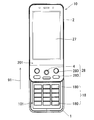
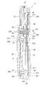
- FIG. 1 is a front view showing a slide type mobile phone according to an embodiment of the present invention.
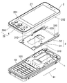
- FIG. 2 is an exploded perspective view of the slide type mobile phone.
- FIG. 3 is a front view used for explaining the closed state of the device body of the slide type mobile phone.
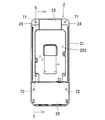
- FIG. 4 is a rear view of the second cabinet constituting the device main body.
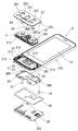
- FIG. 5 is a sectional view taken along line 5-5 shown in FIG.
- FIG. 6 is an exploded perspective view of the second cabinet corresponding to the area A shown in FIG.
- FIG. 7 is an enlarged view of a region A shown in FIG.
- FIG. 8 is an exploded perspective view of the second cabinet corresponding to the region B shown in FIG.
- FIG. 9 is an enlarged view of region B shown in FIG.
- FIG. 1 is a front view showing a slide type mobile phone according to an embodiment of the present invention.
- the slide-type mobile phone includes a device body (10) configured by slidably connecting a first cabinet (1) and a second cabinet (2).
- a first operation section (18) constituted by a plurality of operation keys (180) to (180) is installed.
- a display unit composed of a liquid crystal display panel (27) is installed, while inside the second cabinet (2), there are a lever switch (4) and a plurality of switches.
- a second operation unit (28) composed of the operation keys (280) to (280) is provided.
- a part of the second operation unit (28), that is, the lever switch (4) is operated in a region different from the installation region of the liquid crystal display panel (27). The child (first key top (43) to be described later) and the operator (second key top (282) to be described later) of each operation key (280) are exposed.
- FIG. 2 is an exploded perspective view of the slide type mobile phone.
- a slide mechanism (3) is provided between the first cabinet (1) and the second cabinet (2) so as to be slidable.
- the slide mechanism (3) A slide body (31) and a slide defining portion (32) are included.
- the slide body (31) has an opposing surface on the second cabinet (2) side among the opposing surfaces of the first cabinet (1) and the second cabinet (2) (that is, the rear surface (202 of the second cabinet (2)). )).
- the slide defining portion (32) is a facing surface on the first cabinet (1) side (that is, the first cabinet (1)) among the facing surfaces of the first cabinet (1) and the second cabinet (2).
- the surface (101)) specifically, is fixed to an area different from the installation area of the first operating portion (18).
- the slide defining portion (32) is formed with a pair of left and right guide grooves (320) and (320) at both end positions, and the slide body (31) is formed in the pair of guide grooves (320) and (320).
- the left and right edges (310) and (310) are slidably engaged.
- the slide defining portion (32) defines the slide direction of the slide body (31) in the longitudinal direction (91) of the first cabinet (1).
- the device main body (10) of the slide type mobile phone moves both the first cabinet (1) and the second cabinet (2) relative to each other in the sliding direction, so that both cabinets (1) and (2) as shown in FIG. ) Is closed and the entire first operating section 18 is covered with the second cabinet 2, and both the cabinets 1, 2 are opened as shown in FIG. It is possible to change the state between the open state in which the entirety of) is exposed.
- the user of the slide type mobile phone uses the first operation unit (18) and the second operation unit (28) to slide. It is possible to operate a mobile phone. Further, even when the device main body (10) is set in the closed state as shown in FIG. 3, the user can operate the sliding mobile phone using the second operation unit (28). is there.
- FIG. 4 is a rear view of the second cabinet (2).
- FIG. 5 is a sectional view taken along line 5-5 shown in FIG.
- FIG. 6 is an exploded perspective view of the second cabinet (2), showing a part corresponding to the area A shown in FIG.
- the second cabinet (2) includes a magnesium alloy chassis (21) (corresponding to the first component) as a component constituting the upper portion thereof, and the chassis (21). And a design panel (23) (corresponding to a third component) that forms a part of the back surface (202) of the second cabinet (2) (corresponding to the second component). .
- FIG. 7 is an enlarged view of area A shown in FIG.
- stainless steel is attached to the joint surface (213) on the chassis (21) side among the joint surfaces (213) and (231) of the chassis (21) and the design panel (23).
- the design panel (23) is fastened to the chassis (21) by the first screw member (71) made of steel (SUS) being screwed through the design panel (23).
- the design panel (23) is mounted on the chassis (21) by screwing the first screw member (71) into two places on the joint surface (213) of the chassis (21). It is concluded to 21).
- a screw hole (214) (corresponding to the first screw hole) into which the first screw member (71) is screwed is formed in a bottomed concave shape on the joint surface (213) of the chassis (21).
- the design panel (23) has a through hole (230) (corresponding to the second screw hole) through which the first screw member (71) is inserted.
- a ring-shaped waterproof tape (81) extending around the screw hole (214) of the chassis (21) ( Corresponding to the first seal member).
- the waterproof tape (81) is a waterproof double-sided tape, and is used as a seal member for sealing between the joint surfaces (213) and (231) of the chassis (21) and the design panel (23).
- a cover panel (24) covering the through hole (230) of the design panel (23) is joined to the back surface of the design panel (23).
- a sheet-like waterproof tape (82) is interposed between the joint surfaces (232) and (241) of the design panel (23) and the cover panel (24), and the waterproof tape (82) 23) surrounding the through hole (230) and covering the through hole (230).
- the waterproof tape (82) (corresponding to the second seal member) is a waterproof double-sided tape, and is provided between the joint surfaces (232) and (241) of the design panel (23) and the cover panel (24). It is used as a sealing member for sealing.
- the 1st accommodation chamber R1 in which the 1st screw member (71) is accommodated is formed by the through-hole (230) opened in the design panel (23).
- a ring-shaped waterproof tape (81) is interposed between the joint surfaces (213) and (231) of the chassis (21) and the design panel (23), and the design panel (23) and the cover panel (24)
- a sheet-like waterproof tape (82) is interposed between the joint surfaces (232) and (241).
- the ring-shaped waterproof tape (81) prevents water from entering the first storage chamber R1 through the joint surfaces (213) (231) between the chassis (21) and the design panel (23).
- the sheet-like waterproof tape (82) may prevent water from entering the first storage chamber R1 through the joint surface (232) (241) between the design panel (23) and the cover panel (24).
- the first storage chamber R1 is sealed by the two waterproof tapes (81) and (82). That is, the slide type mobile phone has a waterproof structure that suppresses the entry of water into the first storage chamber R1.
- the chassis (21) is formed of a metal (magnesium alloy in this embodiment) different from the metal (SUS in the present embodiment) constituting the first screw member (71). Therefore, the occurrence of electrolytic corrosion can be suppressed in the chassis (21) and the first screw member (71).
- FIG. 8 is an exploded perspective view of the second cabinet (2), showing a part corresponding to the area B shown in FIG.
- the lever switch (4) includes a rectangular parallelepiped switch body (41) and a lever portion (42) projecting from the switch body (41).
- the lever switch (4) of the present embodiment includes a lever operation that slides the lever portion (42) in a total of eight directions of four directions (up, down, left and right) and four oblique directions with respect to the switch body (41), and the switch body (41).
- the lever can be operated by pushing the lever part (42) toward.
- the lever switch (4) is mounted in the 1st board
- the second cabinet (2) is a magnesium alloy chassis (21) and a part of the surface (201) of the second cabinet (2) joined to the chassis (21) as components constituting the lower part of the second cabinet (2). And a cover member (22).
- a rectangular opening (210) for accommodating the switch body (41) of the lever switch (4) is formed in an area covered by the cover member (22).
- the first board is arranged on the rear side of the chassis (21), and the switch body (41) of the lever switch (4) mounted on the first board is opened in the chassis (21) as shown in FIG. 210) is inserted from the rear side of the chassis (21).
- the switch body (41) is held by the opening (210) of the chassis (21).
- the chassis (21) has a sheet-like second substrate (62) that extends and surrounds the opening (210) of the chassis (21) in an area covered by the cover member (22).
- a dome switch (281) constituting each operation key (280) is mounted on the surface of the second substrate (62).
- the chassis (21) further includes a joining surface (211) to be expanded so as to surround the installation area of the second substrate (62) in an area covered by the cover member (22) and to which the cover member (22) is to be joined. Is formed.
- An annular groove (212) extending so as to surround the installation area of the second substrate (62) is recessed in the joint surface (211).
- FIG. 9 is an enlarged view of region B shown in FIG.
- a waterproof rubber (5) covering the opening (210) of the chassis (21) and the second substrate (62) is provided on the back side of the cover member (22). ing.
- the waterproof rubber (5) has a shape extending to a position overlapping the joint surface (211) of the chassis (21), and the outer edge portion (51) of the waterproof rubber (5) is attached to the chassis (21).
- a seal portion (511) to be fitted into the annular groove (212) is provided so as to project toward the annular groove (212).
- the seal portion (511) of the waterproof rubber (5) is fitted into the annular groove (212) of the chassis (21) and the cover member. (22) is joined to the chassis (21), whereby the seal portion (511) is pressed into the annular groove (212) by the joining surface (220) of the cover member (22). Thereby, the seal portion (511) of the waterproof rubber (5) is fitted into the annular groove (212) without any gap.
- the outer edge portion (51) of the waterproof rubber (5) is interposed between the joint surfaces (211) (220) of the chassis (21) and the cover member (22).
- the waterproof rubber (5) is further formed with a bottomed cylindrical portion (50) into which the tip of the lever portion (42) of the lever switch (4) is inserted.
- the bottomed cylindrical portion (50) opens to the back surface of the waterproof rubber (5) and protrudes from the surface of the waterproof rubber (5). Therefore, an operating force can be applied in various directions from the surface side of the waterproof rubber (5) to the bottomed cylindrical portion (50). Then, when an operating force is applied to the bottomed tubular portion (50), the lever portion (42) of the lever switch (4) moves in the operation direction together with the bottomed tubular portion (50). Therefore, it is possible to suppress the lever operation of the lever switch (4) from being hindered by the waterproof rubber (5).
- a protrusion is formed on the back surface of the waterproof rubber (5) in a region facing each dome switch (281).
- the protrusion comes into contact with the dome switch (281) in the assembled state of the second cabinet (2).
- the pressing force is transmitted to the corresponding dome switch (281) via the protrusions.
- the dome switch (281) is pressed. Therefore, it is possible to suppress the pressing operation of the operation key (280) from being hindered by the waterproof rubber (5).
- a first key top (43) serving as an operator of the lever switch (4) is attached to the bottomed cylindrical portion (50) of the waterproof rubber (5).
- a second key top (282) serving as an operator of the operation key (280) is adhered and fixed at a position overlapping with each dome switch (281).
- the cover member (22) includes a first window (221) for exposing the first key top (43) of the lever switch (4) to the surface of the cover member (22), and each operation key (280). And a second window (222) for exposing the second key top (282) to the surface of the cover member (22). Therefore, the user of the slide type mobile phone can execute the lever operation of the lever switch (4) by applying an operation force to the first key top (43), and each second key top (282). ), An operation of pressing the operation key (280) corresponding to the second key top (282) can be executed.
- the outer edge (51) of the waterproof rubber (5) is interposed between the opposing surfaces of the chassis (21) and the cover member (22). Separate joining surfaces (215) and (223) are formed outside the region where the surfaces (211) and (220) are formed.
- the second screw member (72) made of SUS is screwed into the other joint surface (223) of the cover member (22) through the chassis (21), so that the cover member (22) is attached to the chassis (22). 21).
- the second screw member (72) is screwed into two places on the other joint surface (223) of the cover member (22), thereby covering the cover member (22). Is fastened to the chassis (21).
- a screw hole (224) into which the second screw member (72) is screwed is formed in the other joint surface (223) of the cover member (22) to have a bottomed concave shape.
- a ring-shaped waterproof tape extending around the screw hole (224) of the cover member (22) ( 83).
- the waterproof tape (83) is a waterproof double-sided tape, and is used as a seal member that seals between another joint surface (215) (223) between the chassis (21) and the cover member (22). ing.
- a rear panel (25) covering the through hole (216) of the chassis (21) is joined to the rear surface of the chassis (21).
- the joint surface (217) (251) between the chassis (21) and the back panel (25) includes a frame-shaped waterproof tape (84) extending so as to surround the through hole (216) of the chassis (21). is doing.
- the waterproof tape (84) is a waterproof double-sided tape, and is used as a seal member for sealing between the joint surfaces (217) and (251) of the chassis (21) and the back panel (25). .
- a metal plate (26) is interposed between the chassis (21) and the back panel (25), and an outer edge portion of the metal plate (26) A notch (260) through which the second screw member (72) is inserted is provided. Then, as shown in FIG. 9, the second screw member (72) passes through the notch (260) of the metal plate (26) and the through hole (216) of the chassis (21), and the cover member (22). The metal plate (26) is also fastened to the chassis (21) by being screwed into the screw hole (224).
- the water is waterproof rubber ( 5) is suppressed from passing. Accordingly, the infiltrated water stays on the surface of the waterproof rubber (5) or moves along the surface of the waterproof rubber (5).
- the outer edge portion (51) of the waterproof rubber (5) is interposed between the joint surfaces (211) (220) of the chassis (21) and the cover member (22), and the seal portion (511) is an annular groove. (212) is fitted with no gap.
- a bottomed cylindrical shape formed on another joining surface (223) of the cover member (22) inside the second cabinet (2).
- a second accommodation chamber R2 in which the second screw member (72) is accommodated is formed by the screw hole (224) and the through hole (216) provided in the chassis (21).
- the second storage chamber R2 communicates with the opening (210) of the chassis (21) through a gap G formed between the chassis (21) and the back panel (25). ing.
- a ring-shaped waterproof tape (83) is interposed between another joint surface (215) (223) of the chassis (21) and the cover member (22), and the chassis (21) and the rear panel (25)
- a frame-shaped waterproof tape (84) is interposed between the joint surfaces (217) and (251). Accordingly, the ring-shaped waterproof tape (83) prevents water from entering the second storage chamber R2 through another joint surface (215) (223) between the chassis (21) and the cover member (22).
- the frame-shaped waterproof tape (84) is suppressed and water can enter the second storage chamber R2 through the joint surface (217) (251) between the chassis (21) and the rear panel (25). It will be suppressed by.
- the second storage chamber R2, the gap G, the opening (210) of the chassis (21), and the region on the surface of the second substrate (62) are sealed. That is, the slide type mobile phone suppresses the intrusion of water into the second storage chamber R2, the gap G, the opening (210) for storing the lever switch (4), and the region on the surface of the second substrate (62). It will have a waterproof structure.
- the chassis (21) is formed of a metal (magnesium alloy in the present embodiment) different from the metal (SUS in the present embodiment) constituting the second screw member (72). Therefore, the occurrence of electrolytic corrosion can be suppressed in the chassis (21) and the second screw member (72).
- each part of the present invention is not limited to the above embodiment, and various modifications can be made within the technical scope described in the claims.
- various configurations adopted in the above-described slide type mobile phone can be applied to various mobile phones such as a foldable mobile phone and a straight type mobile phone.
- the various configurations employed in the slide type mobile phone are not limited to the mobile phone but can be applied to various electronic devices such as a PDA (Personal Digital Assistant), a digital camera, and a video camera.
- PDA Personal Digital Assistant
- the configuration of the above-described slide-type mobile phone is only an example of the present invention, and the present invention relates to various electronic devices in which a plurality of components constituting the device main body (10) are formed from various dissimilar metals. It can be applied to.
Landscapes
- Engineering & Computer Science (AREA)
- Signal Processing (AREA)
- Telephone Set Structure (AREA)
- Casings For Electric Apparatus (AREA)
Priority Applications (1)
| Application Number | Priority Date | Filing Date | Title |
|---|---|---|---|
| US13/635,320 US9002417B2 (en) | 2010-03-29 | 2011-03-28 | Electronic device |
Applications Claiming Priority (2)
| Application Number | Priority Date | Filing Date | Title |
|---|---|---|---|
| JP2010-074314 | 2010-03-29 | ||
| JP2010074314A JP5567877B2 (ja) | 2010-03-29 | 2010-03-29 | 電子機器 |
Publications (1)
| Publication Number | Publication Date |
|---|---|
| WO2011122569A1 true WO2011122569A1 (ja) | 2011-10-06 |
Family
ID=44712264
Family Applications (1)
| Application Number | Title | Priority Date | Filing Date |
|---|---|---|---|
| PCT/JP2011/057664 Ceased WO2011122569A1 (ja) | 2010-03-29 | 2011-03-28 | 電子機器 |
Country Status (3)
| Country | Link |
|---|---|
| US (1) | US9002417B2 (enExample) |
| JP (1) | JP5567877B2 (enExample) |
| WO (1) | WO2011122569A1 (enExample) |
Families Citing this family (6)
| Publication number | Priority date | Publication date | Assignee | Title |
|---|---|---|---|---|
| JP5554603B2 (ja) * | 2010-03-25 | 2014-07-23 | 京セラ株式会社 | 電子機器 |
| KR101395358B1 (ko) * | 2011-09-02 | 2014-05-14 | 주식회사 팬택 | 방수시트가 설치되는 이동통신 단말기 및 그 제조방법 |
| JP6028654B2 (ja) * | 2013-03-27 | 2016-11-16 | 富士通株式会社 | 充電端子付筺体及び該筺体を備える電子装置 |
| US9743554B2 (en) * | 2015-11-18 | 2017-08-22 | Microsoft Technology Licensing, Llc | Heat dissipation in electronics with a heat spreader |
| US20190054532A1 (en) * | 2017-08-21 | 2019-02-21 | Divergent Technologies, Inc. | Systems and methods for bridging components |
| JP6781390B1 (ja) * | 2019-09-25 | 2020-11-04 | 富士通クライアントコンピューティング株式会社 | 電子機器 |
Citations (3)
| Publication number | Priority date | Publication date | Assignee | Title |
|---|---|---|---|---|
| JP2007227111A (ja) * | 2006-02-22 | 2007-09-06 | Polymatech Co Ltd | コネクタシート及び携帯型電子機器 |
| JP2008106932A (ja) * | 2006-09-28 | 2008-05-08 | Casio Hitachi Mobile Communications Co Ltd | 筐体の防水構造 |
| JP2009267550A (ja) * | 2008-04-23 | 2009-11-12 | Casio Hitachi Mobile Communications Co Ltd | 携帯電子機器 |
Family Cites Families (2)
| Publication number | Priority date | Publication date | Assignee | Title |
|---|---|---|---|---|
| KR100877049B1 (ko) * | 2006-09-28 | 2009-01-07 | 가시오 히타치 모바일 커뮤니케이션즈 컴퍼니 리미티드 | 방수구조 |
| JP2010056810A (ja) | 2008-08-28 | 2010-03-11 | Kyocera Corp | 小型電子機器の筐体構造 |
-
2010
- 2010-03-29 JP JP2010074314A patent/JP5567877B2/ja not_active Expired - Fee Related
-
2011
- 2011-03-28 WO PCT/JP2011/057664 patent/WO2011122569A1/ja not_active Ceased
- 2011-03-28 US US13/635,320 patent/US9002417B2/en not_active Expired - Fee Related
Patent Citations (3)
| Publication number | Priority date | Publication date | Assignee | Title |
|---|---|---|---|---|
| JP2007227111A (ja) * | 2006-02-22 | 2007-09-06 | Polymatech Co Ltd | コネクタシート及び携帯型電子機器 |
| JP2008106932A (ja) * | 2006-09-28 | 2008-05-08 | Casio Hitachi Mobile Communications Co Ltd | 筐体の防水構造 |
| JP2009267550A (ja) * | 2008-04-23 | 2009-11-12 | Casio Hitachi Mobile Communications Co Ltd | 携帯電子機器 |
Also Published As
| Publication number | Publication date |
|---|---|
| US9002417B2 (en) | 2015-04-07 |
| JP5567877B2 (ja) | 2014-08-06 |
| US20130005409A1 (en) | 2013-01-03 |
| JP2011211280A (ja) | 2011-10-20 |
Similar Documents
| Publication | Publication Date | Title |
|---|---|---|
| JP5567877B2 (ja) | 電子機器 | |
| JP4738199B2 (ja) | 電子機器 | |
| JP5000243B2 (ja) | 電子機器 | |
| JP5909655B2 (ja) | 電子機器 | |
| US8014139B2 (en) | Compact and light computer casing structure | |
| US20070025069A1 (en) | Electronic apparatus provided with housing having liquid proof structure | |
| JP2012065044A (ja) | 携帯端末装置 | |
| US10886077B2 (en) | Mobile terminal | |
| JP5567879B2 (ja) | スライド式携帯電子機器 | |
| US20190096610A1 (en) | Electronic device | |
| US8255019B2 (en) | Slidable portable electronic device | |
| JP5554603B2 (ja) | 電子機器 | |
| JP5945456B2 (ja) | 携帯電子機器 | |
| JP2010176261A (ja) | 電子機器及びその製造方法 | |
| WO2011074682A1 (ja) | 筐体、電子装置および表示パネルの収容方法 | |
| JP4985552B2 (ja) | 防水窓構造、及び電子機器 | |
| JP6598060B2 (ja) | 情報処理装置及び情報処理装置製造方法 | |
| JP5321514B2 (ja) | 携帯端末装置 | |
| JP6086296B2 (ja) | 表示装置内蔵パネル取付機器 | |
| JP4959197B2 (ja) | 表示機器 | |
| JP2006287313A (ja) | 電子機器の防水構造 | |
| JP5291562B2 (ja) | 電子機器 | |
| JP6233030B2 (ja) | リモコン | |
| JP2008035115A (ja) | 携帯電子機器 | |
| JP2007157510A (ja) | キーボタンを有する携帯電子機器の浸入液体導水構造 |
Legal Events
| Date | Code | Title | Description |
|---|---|---|---|
| 121 | Ep: the epo has been informed by wipo that ep was designated in this application |
Ref document number: 11762793 Country of ref document: EP Kind code of ref document: A1 |
|
| WWE | Wipo information: entry into national phase |
Ref document number: 13635320 Country of ref document: US |
|
| NENP | Non-entry into the national phase |
Ref country code: DE |
|
| 122 | Ep: pct application non-entry in european phase |
Ref document number: 11762793 Country of ref document: EP Kind code of ref document: A1 |