WO2011122419A1 - 水素製造装置及び燃料電池システム - Google Patents
水素製造装置及び燃料電池システム Download PDFInfo
- Publication number
- WO2011122419A1 WO2011122419A1 PCT/JP2011/057014 JP2011057014W WO2011122419A1 WO 2011122419 A1 WO2011122419 A1 WO 2011122419A1 JP 2011057014 W JP2011057014 W JP 2011057014W WO 2011122419 A1 WO2011122419 A1 WO 2011122419A1
- Authority
- WO
- WIPO (PCT)
- Prior art keywords
- unit
- water
- water surface
- reforming
- production apparatus
- Prior art date
- Legal status (The legal status is an assumption and is not a legal conclusion. Google has not performed a legal analysis and makes no representation as to the accuracy of the status listed.)
- Ceased
Links
Images



Classifications
-
- C—CHEMISTRY; METALLURGY
- C01—INORGANIC CHEMISTRY
- C01B—NON-METALLIC ELEMENTS; COMPOUNDS THEREOF; METALLOIDS OR COMPOUNDS THEREOF NOT COVERED BY SUBCLASS C01C
- C01B3/00—Hydrogen; Gaseous mixtures containing hydrogen; Separation of hydrogen from mixtures containing it; Purification of hydrogen; Reversible storage of hydrogen
- C01B3/50—Separation of hydrogen or hydrogen-containing gases from gaseous mixtures, e.g. purification
- C01B3/56—Separation of hydrogen or hydrogen-containing gases from gaseous mixtures, e.g. purification by contacting with solids; Regeneration of used solids
- C01B3/58—Separation of hydrogen or hydrogen-containing gases from gaseous mixtures, e.g. purification by contacting with solids; Regeneration of used solids including a catalytic reaction
- C01B3/583—Separation of hydrogen or hydrogen-containing gases from gaseous mixtures, e.g. purification by contacting with solids; Regeneration of used solids including a catalytic reaction the reaction being the selective oxidation of carbon monoxide
-
- C—CHEMISTRY; METALLURGY
- C01—INORGANIC CHEMISTRY
- C01B—NON-METALLIC ELEMENTS; COMPOUNDS THEREOF; METALLOIDS OR COMPOUNDS THEREOF NOT COVERED BY SUBCLASS C01C
- C01B3/00—Hydrogen; Gaseous mixtures containing hydrogen; Separation of hydrogen from mixtures containing it; Purification of hydrogen; Reversible storage of hydrogen
- C01B3/02—Production of hydrogen; Production of gaseous mixtures containing hydrogen
- C01B3/32—Production of hydrogen; Production of gaseous mixtures containing hydrogen by reaction of gaseous or liquid organic compounds with gasifying agents, e.g. water, carbon dioxide or air
- C01B3/34—Production of hydrogen; Production of gaseous mixtures containing hydrogen by reaction of gaseous or liquid organic compounds with gasifying agents, e.g. water, carbon dioxide or air by reaction of hydrocarbons with gasifying agents
- C01B3/38—Production of hydrogen; Production of gaseous mixtures containing hydrogen by reaction of gaseous or liquid organic compounds with gasifying agents, e.g. water, carbon dioxide or air by reaction of hydrocarbons with gasifying agents using catalysts
-
- C—CHEMISTRY; METALLURGY
- C01—INORGANIC CHEMISTRY
- C01B—NON-METALLIC ELEMENTS; COMPOUNDS THEREOF; METALLOIDS OR COMPOUNDS THEREOF NOT COVERED BY SUBCLASS C01C
- C01B3/00—Hydrogen; Gaseous mixtures containing hydrogen; Separation of hydrogen from mixtures containing it; Purification of hydrogen; Reversible storage of hydrogen
- C01B3/02—Production of hydrogen; Production of gaseous mixtures containing hydrogen
- C01B3/32—Production of hydrogen; Production of gaseous mixtures containing hydrogen by reaction of gaseous or liquid organic compounds with gasifying agents, e.g. water, carbon dioxide or air
- C01B3/34—Production of hydrogen; Production of gaseous mixtures containing hydrogen by reaction of gaseous or liquid organic compounds with gasifying agents, e.g. water, carbon dioxide or air by reaction of hydrocarbons with gasifying agents
- C01B3/48—Production of hydrogen; Production of gaseous mixtures containing hydrogen by reaction of gaseous or liquid organic compounds with gasifying agents, e.g. water, carbon dioxide or air by reaction of hydrocarbons with gasifying agents followed by reaction of water vapour with carbon monoxide
-
- H—ELECTRICITY
- H01—ELECTRIC ELEMENTS
- H01M—PROCESSES OR MEANS, e.g. BATTERIES, FOR THE DIRECT CONVERSION OF CHEMICAL ENERGY INTO ELECTRICAL ENERGY
- H01M8/00—Fuel cells; Manufacture thereof
- H01M8/06—Combination of fuel cells with means for production of reactants or for treatment of residues
- H01M8/0606—Combination of fuel cells with means for production of reactants or for treatment of residues with means for production of gaseous reactants
- H01M8/0612—Combination of fuel cells with means for production of reactants or for treatment of residues with means for production of gaseous reactants from carbon-containing material
- H01M8/0625—Combination of fuel cells with means for production of reactants or for treatment of residues with means for production of gaseous reactants from carbon-containing material in a modular combined reactor/fuel cell structure
- H01M8/0631—Reactor construction specially adapted for combination reactor/fuel cell
-
- H—ELECTRICITY
- H01—ELECTRIC ELEMENTS
- H01M—PROCESSES OR MEANS, e.g. BATTERIES, FOR THE DIRECT CONVERSION OF CHEMICAL ENERGY INTO ELECTRICAL ENERGY
- H01M8/00—Fuel cells; Manufacture thereof
- H01M8/06—Combination of fuel cells with means for production of reactants or for treatment of residues
- H01M8/0662—Treatment of gaseous reactants or gaseous residues, e.g. cleaning
- H01M8/0668—Removal of carbon monoxide or carbon dioxide
-
- C—CHEMISTRY; METALLURGY
- C01—INORGANIC CHEMISTRY
- C01B—NON-METALLIC ELEMENTS; COMPOUNDS THEREOF; METALLOIDS OR COMPOUNDS THEREOF NOT COVERED BY SUBCLASS C01C
- C01B2203/00—Integrated processes for the production of hydrogen or synthesis gas
- C01B2203/02—Processes for making hydrogen or synthesis gas
- C01B2203/0205—Processes for making hydrogen or synthesis gas containing a reforming step
- C01B2203/0227—Processes for making hydrogen or synthesis gas containing a reforming step containing a catalytic reforming step
- C01B2203/0233—Processes for making hydrogen or synthesis gas containing a reforming step containing a catalytic reforming step the reforming step being a steam reforming step
-
- C—CHEMISTRY; METALLURGY
- C01—INORGANIC CHEMISTRY
- C01B—NON-METALLIC ELEMENTS; COMPOUNDS THEREOF; METALLOIDS OR COMPOUNDS THEREOF NOT COVERED BY SUBCLASS C01C
- C01B2203/00—Integrated processes for the production of hydrogen or synthesis gas
- C01B2203/02—Processes for making hydrogen or synthesis gas
- C01B2203/0283—Processes for making hydrogen or synthesis gas containing a CO-shift step, i.e. a water gas shift step
- C01B2203/0288—Processes for making hydrogen or synthesis gas containing a CO-shift step, i.e. a water gas shift step containing two CO-shift steps
-
- C—CHEMISTRY; METALLURGY
- C01—INORGANIC CHEMISTRY
- C01B—NON-METALLIC ELEMENTS; COMPOUNDS THEREOF; METALLOIDS OR COMPOUNDS THEREOF NOT COVERED BY SUBCLASS C01C
- C01B2203/00—Integrated processes for the production of hydrogen or synthesis gas
- C01B2203/04—Integrated processes for the production of hydrogen or synthesis gas containing a purification step for the hydrogen or the synthesis gas
- C01B2203/0435—Catalytic purification
- C01B2203/044—Selective oxidation of carbon monoxide
-
- C—CHEMISTRY; METALLURGY
- C01—INORGANIC CHEMISTRY
- C01B—NON-METALLIC ELEMENTS; COMPOUNDS THEREOF; METALLOIDS OR COMPOUNDS THEREOF NOT COVERED BY SUBCLASS C01C
- C01B2203/00—Integrated processes for the production of hydrogen or synthesis gas
- C01B2203/04—Integrated processes for the production of hydrogen or synthesis gas containing a purification step for the hydrogen or the synthesis gas
- C01B2203/0465—Composition of the impurity
- C01B2203/047—Composition of the impurity the impurity being carbon monoxide
-
- C—CHEMISTRY; METALLURGY
- C01—INORGANIC CHEMISTRY
- C01B—NON-METALLIC ELEMENTS; COMPOUNDS THEREOF; METALLOIDS OR COMPOUNDS THEREOF NOT COVERED BY SUBCLASS C01C
- C01B2203/00—Integrated processes for the production of hydrogen or synthesis gas
- C01B2203/06—Integration with other chemical processes
- C01B2203/066—Integration with other chemical processes with fuel cells
-
- C—CHEMISTRY; METALLURGY
- C01—INORGANIC CHEMISTRY
- C01B—NON-METALLIC ELEMENTS; COMPOUNDS THEREOF; METALLOIDS OR COMPOUNDS THEREOF NOT COVERED BY SUBCLASS C01C
- C01B2203/00—Integrated processes for the production of hydrogen or synthesis gas
- C01B2203/16—Controlling the process
- C01B2203/1685—Control based on demand of downstream process
-
- Y—GENERAL TAGGING OF NEW TECHNOLOGICAL DEVELOPMENTS; GENERAL TAGGING OF CROSS-SECTIONAL TECHNOLOGIES SPANNING OVER SEVERAL SECTIONS OF THE IPC; TECHNICAL SUBJECTS COVERED BY FORMER USPC CROSS-REFERENCE ART COLLECTIONS [XRACs] AND DIGESTS
- Y02—TECHNOLOGIES OR APPLICATIONS FOR MITIGATION OR ADAPTATION AGAINST CLIMATE CHANGE
- Y02E—REDUCTION OF GREENHOUSE GAS [GHG] EMISSIONS, RELATED TO ENERGY GENERATION, TRANSMISSION OR DISTRIBUTION
- Y02E60/00—Enabling technologies; Technologies with a potential or indirect contribution to GHG emissions mitigation
- Y02E60/30—Hydrogen technology
- Y02E60/50—Fuel cells
Definitions
- the present invention relates to a hydrogen production apparatus and a fuel cell system.
- a reformed gas containing hydrogen is generated by reforming raw fuel such as hydrocarbons, and electric power is generated in the fuel cell stack using the reformed gas.
- the hydrogen production apparatus in such a fuel cell system has a structure in which a cylindrical exhaust passage for circulating exhaust gas from a burner used for a reforming reaction is surrounded by a cylindrical evaporator, and the evaporator stores water. At the same time, the water is evaporated by the heat of the exhaust gas to supply water vapor to the reforming section.
- the reforming part is set to a constant value of S / C (Steam to Carbon ratio) indicating the molar ratio of the amount of water vapor to carbon in the raw fuel.
- S / C Steam to Carbon ratio
- the amount of electric power required for the fuel cell system that is, the usage status of electric devices that consume electric power
- the load of the fuel cell stack also varies.
- the load fluctuates in this way, the water level in the evaporation section (boundary between the water layer and the steam layer) fluctuates, which causes a problem that water evaporates and the flow rate of the reformed gas is not stable. It was.
- an object of the present invention is to provide a hydrogen production apparatus and a fuel cell system that can stably generate reformed gas.
- the hydrogen production apparatus includes a reforming unit that generates a reformed gas containing hydrogen by reforming raw fuel, a burner that heats the reforming unit, water, and at least the heat of exhaust gas from the burner.
- a reforming unit that generates a reformed gas containing hydrogen by reforming raw fuel
- a burner that heats the reforming unit, water, and at least the heat of exhaust gas from the burner.
- the evaporating unit generates water vapor by collecting water and recovering heat in the apparatus, and supplies the water vapor to the reforming unit. Therefore, there is a possibility that the position of the water surface in the evaporation section varies due to the variation in the load of the fuel cell stack.
- the control unit changes the ratio (for example, S / C) between the amount of raw fuel supplied to the reforming unit and the amount of water vapor supplied to the reforming unit to make the position of the water surface constant. be able to. As a result, it is possible to suppress the evaporation vibration due to the water surface change during the load fluctuation, and to stably generate the reformed gas.
- the hydrogen production apparatus further includes a selective oxidation reaction unit that is arranged adjacent to the evaporation unit, and selectively oxidizes carbon monoxide in the reformed gas generated by the reforming unit using the selective oxidation catalyst layer.
- the controller may adjust the position of the water surface so that the position of the water surface is above the upper end of the selective oxidation catalyst layer. Since the selective oxidation reaction parts are arranged adjacent to the evaporation part, the selective oxidation catalyst layer can be cooled by the evaporation part, and the evaporation part can recover heat from the selective oxidation catalyst layer. It becomes.
- the controller can adjust the position of the water surface so that the position of the water surface is above the upper end of the selective oxidation catalyst layer, it is possible to reliably prevent the temperature of the selective oxidation catalyst layer from rapidly increasing. .
- the control unit acquires a load command to the fuel cell stack that generates power with the reformed gas, and calculates a ratio between the amount of raw fuel and the amount of water vapor based on the acquired load command. It may be changed.
- the water surface ratio is suppressed by increasing the water vapor ratio, so that the position of the water surface can be adjusted in real time following the load fluctuation. Therefore, the position of the water surface can be made constant and the evaporation vibration due to the water surface change during load fluctuation can be more reliably suppressed.
- the hydrogen production apparatus further includes a water surface position detection unit that is provided in the evaporation unit and detects the position of the water surface, and the control unit calculates the amount of raw fuel based on the position of the water surface detected by the water surface detection unit.
- the ratio to the amount of water vapor may be changed.
- the fuel cell system includes the hydrogen production apparatus and a fuel cell stack that generates power using the reformed gas generated by the hydrogen production apparatus.
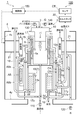
- FIG. 1 is a schematic block diagram showing a part of a fuel cell system according to an embodiment. It is a schematic front end view which shows the hydrogen production apparatus of FIG. It is a flowchart which shows the content of the 1st control process by the hydrogen production apparatus which concerns on embodiment. It is an example of the map used in the control amount setting process shown in FIG. It is a flowchart which shows the 2nd control processing by the hydrogen production apparatus which concerns on embodiment. It is a schematic front end view which shows the hydrogen production apparatus which concerns on a modification.
- FIG. 1 is a schematic block diagram showing a part of a fuel cell system according to an embodiment.
- a hydrogen production apparatus (FPS: Fuel Processing System) 1 is used as a hydrogen supply source in a fuel cell system 100 for home use, for example.
- the hydrogen production apparatus 1 here uses petroleum-based hydrocarbons as a raw fuel, and supplies a reformed gas containing hydrogen to a cell stack (fuel cell stack) 20.
- alcohols, ethers, biofuels, natural gas, and city gas may be used as raw fuel.
- petroleum-based hydrocarbons, naphtha, light oil, etc. can be used as raw fuel in addition to kerosene and LP gas.
- various types such as a solid polymer type, an alkaline electrolyte type, a phosphoric acid type, a molten carbonate type, or a solid oxide type may be used.
- FIG. 2 is a schematic front end view showing the hydrogen production apparatus of FIG.
- the hydrogen production apparatus 1 includes a desulfurization part 2 having a cylindrical outer shape with a central axis as an axis G, and a main body part 3 with a cylindrical outer shape having a central axis as an axis G. These are accommodated in the housing 4. Further, in the casing 4, the surroundings of the desulfurization part 2 and the main body part 3 are filled with a powdery heat insulating material (not shown) to be insulated.
- the desulfurization unit 2 may be installed outside the housing 4.
- the desulfurization unit 2 desulfurizes raw fuel introduced from the outside with a desulfurization catalyst to remove sulfur, and supplies the raw fuel to a feed unit 5 described later.
- the desulfurization part 2 is fixed to the side plate 4x of the housing 4 with a pipe, and is held so as to surround the upper part of the main body part 3 with a predetermined gap.
- the main body 3 includes a feed unit 5, a reforming unit 6, a shift reaction unit 7, a selective oxidation reaction unit 8, and an evaporation unit 9, which are integrally configured.
- the main body 3 is fixed and held on a floor plate 4y of the housing 4 by a cylindrical stay.
- the feed unit 5 mixes the raw fuel and steam (steam) desulfurized in the desulfurization unit 2 and supplies them to the reforming unit 6.
- the feed unit 5 includes a mixing unit 5x that combines and mixes raw fuel and water vapor to generate a mixed gas (mixed fluid), and a mixed gas channel 5y that distributes the mixed gas to the reforming unit 6. , Including.
- the reforming unit (SR: Steam Reforming) 6 steam-reforms the mixed gas supplied from the feed unit 5 with the reforming catalyst 6x to generate a reformed gas, and supplies the reformed gas to the shift reaction unit 7.
- the reforming part 6 has a cylindrical outer shape with the central axis as the axis G, and is provided on the upper end side of the main body part 3 so as to be located in the cylinder of the desulfurization part 2.
- the burner 10 is used as a heat source for heating the reforming catalyst 6x of the reforming section 6.
- raw fuel is supplied as burner fuel from the outside and burned.
- the burner 10 is attached to a combustion cylinder 11 provided at the upper end of the main body 3 and having the axis G as a central axis so that a flame by the burner 10 is surrounded.
- a part of the raw fuel desulfurized in the desulfurization unit 2 may be supplied as burner fuel and burned.
- the shift reaction unit 7 is for lowering the carbon monoxide concentration (CO concentration) of the reformed gas supplied from the reforming unit 6, and shifts the carbon monoxide in the reformed gas to generate hydrogen and Convert to carbon dioxide.
- the shift reaction section 7 can perform the shift reaction in two stages, and performs a high temperature shift reaction that is a shift reaction at a high temperature (for example, 400 ° C. to 600 ° C.).
- HTS High Temperature Shift
- LTS LowTemperature Shift 13 for performing a low temperature shift reaction that is a shift reaction at a temperature lower than the temperature of the high temperature shift reaction (for example, 150 ° C to 350 ° C).
- the high temperature shift reaction unit 12 is not necessarily provided.
- the high temperature shift reaction unit 12 causes the carbon monoxide in the reformed gas supplied from the reforming unit 6 to undergo a high temperature shift reaction with the high temperature shift catalyst 12x, thereby reducing the CO concentration of the reformed gas.
- the high temperature shift reaction section 12 has a cylindrical outer shape with the central axis as the axis G, and is disposed adjacent to the radially outer side of the reforming section 6 so that the high temperature shift catalyst 12x surrounds the lower end of the reforming catalyst 6x. ing.
- the high temperature shift reaction unit 12 supplies the reformed gas having a reduced CO concentration to the low temperature shift reaction unit 13.
- the low temperature shift reaction unit 13 causes the carbon monoxide in the reformed gas subjected to the high temperature shift reaction in the high temperature shift reaction unit 12 to undergo a low temperature shift reaction by the low temperature shift catalyst 13x, thereby reducing the CO concentration of the reformed gas.
- the low temperature shift reaction part 13 has a cylindrical outer shape with the central axis as the axis G, and is disposed on the lower end side of the main body part 3.
- the low temperature shift reaction unit 13 supplies the reformed gas having a reduced CO concentration to the selective oxidation reaction unit 8 via the reformed gas pipe 14x.
- a selective oxidation reaction unit (PROX) 8 further reduces the CO concentration in the reformed gas subjected to the low temperature shift reaction in the low temperature shift reaction unit 13. This is because if a high concentration of carbon monoxide is supplied to the cell stack 20, the catalyst of the cell stack 20 is poisoned and the performance is greatly reduced. Specifically, the selective oxidation reaction section 8 reacts carbon monoxide in the reformed gas with air introduced through the air pipe 15 by the selective oxidation catalyst 8x, thereby converting hydrogen in the reformed gas. Without oxidizing, carbon monoxide is selectively oxidized and converted to carbon dioxide.
- the selective oxidation reaction portion 8 has a cylindrical outer shape with the central axis as the axis G, and is disposed so as to constitute the outermost peripheral side of the main body portion 3 from the lower end of the main body portion 3 to the upper end side of a predetermined length. .
- the selective oxidation reaction unit 8 guides the reformed gas whose CO concentration is further reduced to the outside through the reformed gas pipe 14y provided with the heat exchange unit 16.
- the heat exchanging unit 16 exchanges heat between the reformed gas flowing through the reformed gas pipe 14y and the water introduced from the outside through the water pipe 17x, and supplies the water to the evaporator 9 Supply via the pipe 17y.
- the evaporation unit 9 stores the water supplied from the heat exchange unit 16 and moves the water from the heat from the exhaust gas from the burner 10, the low temperature shift reaction unit 13 and the selective oxidation reaction unit 8 (low temperature shift). It is vaporized with heat (obtained by cooling the reaction section 13 and the selective oxidation reaction section 8) to generate water vapor.
- the evaporator 9 is of a jacket type and has a cylindrical shape with the central axis as the axis G.
- the evaporation unit 9 is located radially outside the high temperature shift reaction unit 12 and the low temperature shift reaction unit 13 and inside the selective oxidation reaction unit 8 (that is, between the shift reaction unit 7 and the selective oxidation reaction unit 8). It is arranged to be located.
- the evaporation unit 9 supplies the generated water vapor to the mixing unit 5x of the feed unit 5 via the water vapor pipe 17z.
- the raw fuel desulfurized in the desulfurization unit 2 and the water vapor from the evaporation unit 9 are mixed in the mixing unit 5x to generate a mixed gas.
- This mixed gas is supplied to the reforming unit 6 via the mixed gas flow path 5y and steam reformed by the reforming catalyst 6x, thereby generating a reformed gas.
- the generated reformed gas has its carbon monoxide concentration lowered to, for example, about several thousand ppm by the shift reaction unit 7, and after its carbon monoxide concentration has been lowered to about 10 ppm or less by the selective oxidation reaction unit 8. Then, it is cooled by the heat exchange unit 16 and led out to the cell stack 20 at the subsequent stage.
- the temperature of each part is set as follows in order to suitably perform the catalytic reaction with the respective catalysts 6x, 12x, 13x, and 8x. That is, the temperature of the mixed gas flowing into the reforming unit 6 is set to about 300 to 550 ° C., and the temperature of the reformed gas flowing out of the reforming unit 6 is set to 550 ° C. to 800 ° C. and flows into the high temperature shift reaction unit 12 The temperature of the reformed gas is 400 to 600 ° C., and the temperature of the reformed gas flowing out from the high temperature shift reaction unit 12 is 300 to 500 ° C. Further, the temperature of the reformed gas flowing into the low temperature shift reaction unit 13 is set to 150 ° C.
- the temperature of the reformed gas flowing out from the low temperature shift reaction unit 13 is set to 150 ° C. to 250 ° C.
- the temperature of the reformed gas flowing into 8 is set to 90 ° C. to 210 ° C. (120 ° C. to 190 ° C.).
- the fuel cell system 100 and the hydrogen production apparatus 1 have a function of making the position of the water surface WF of the water stored in the evaporator 9 constant. Further, the fuel cell system 100 and the hydrogen production apparatus 1 have a function of adjusting the position of the water surface WF so that the position of the water surface WF is above the upper end A8a of the selective oxidation catalyst layer A8 of the selective oxidation reaction unit 8. ing.
- the water surface WF is a boundary portion where water in the evaporator 9 becomes water vapor.
- the position of the water surface WF is constant means not only a situation in which the position of the water surface WF is not changed at all, but also within a predetermined range (for example, the temperature sensor C2) as long as the performance of the hydrogen production apparatus 1 is not affected. And the range of the temperature sensor C3).
- the fuel cell system 100 further includes a load detection sensor CE.
- the hydrogen production apparatus 1 further includes a raw fuel supply pump 110, a water supply pump 120, a burner fuel supply pump 130, a burner air supply pump 140, temperature sensors C1, C2, C3, C4, and C5, and a control unit 150. Yes.
- the load detection sensor CE has a function of detecting a load command to the cell stack 20.
- the load of the cell stack 20 is the amount of electric power (W) required for the cell stack 20, and varies depending on, for example, the usage status of electric equipment used in the home. As the power consumption of the electric equipment used increases, the load on the cell stack 20 increases. On the other hand, when the power consumption of the electric equipment used is reduced, the load on the cell stack 20 is reduced.
- the load detection sensor CE is electrically connected to the control unit 150 and outputs a detection result to the control unit 150 (note that some electrical connection relationships are omitted in the figure).
- the raw fuel supply pump 110 is a pump that supplies raw fuel to the reforming unit 6.
- the water supply pump 120 is a pump that supplies water to the evaporation unit 9 through the water pipe 17x.
- the burner fuel supply pump 130 is a pump that supplies burner fuel to the burner 10.
- the air supply pump 140 is a pump that supplies air to the burner 10.
- Each pump is electrically connected to the control unit 150 and is driven based on a control signal input from the control unit 150. In addition, arrangement
- Temperature sensors C1, C2, C3, C4, and C5 are sensors that detect the position of the water surface WF by detecting the temperature in the water vapor pipe 17z or the evaporation unit 9.
- the temperature sensor C1 is provided in the vicinity of the connection part EP of the water vapor pipe 17z connected to the upper end side of the evaporation part 9. Thus, the temperature sensor C1 can detect the temperature of the water vapor from the evaporation unit 9 toward the feed unit 5.
- the temperature sensors C2, C3, C4, and C5 are provided in the evaporation unit 9 in this order from top to bottom.
- the temperature sensor C2 and the temperature sensor C3 are disposed between the connection portion EP and the upper end A8a of the selective oxidation catalyst layer A8 in the height direction.
- the temperature sensor C4 and the temperature sensor C5 are disposed between the upper end A8a and the lower end A8b of the selective oxidation catalyst layer A8 in the height direction.
- the selective oxidation catalyst layer A8 is arranged adjacent to the evaporation section 9 so as to be cooled by the evaporation section 9 over the entire region from the upper end A8a to the lower end A8b.
- the selective oxidation reaction unit 8 may be configured so as to be adjacent to the evaporation unit 9 by being directly attached to the outer peripheral surface of the evaporation unit 9, such as a flow path or a gap therebetween.
- the configuration may be adjacent to the evaporation unit 9 with a space interposed therebetween, and is not particularly limited as long as the selective oxidation catalyst layer A8 can be cooled by the evaporation unit 9.
- the temperature sensors C1, C2, C3, C4, and C5 those disposed above the water surface WF detect the temperature of water vapor, and thus detect a temperature significantly higher than 100 ° C.
- those disposed below the water surface WF detect the temperature of water, and therefore detect temperatures below 100 ° C. or near 100 ° C. . Accordingly, the temperature sensors C1, C2, C3, C4, and C5 can detect the position of the water surface WF based on the detection value of each sensor.
- the position of the water surface WF is detected to be between the temperature sensor C2 and the temperature sensor C3 (FIG. 4). (See (b)).
- the temperature sensors C4 and C5 may not be provided.
- the temperature sensors C1, C2, C3, C4, and C5 may not be provided.
- the control unit 150 has a function of controlling the entire hydrogen production apparatus 1.
- a device that performs electronic control for example, a CPU (Central Processing Unit), a ROM (Read Only Memory), a RAM (Random Access Memory), And a device configured to include an input / output interface).
- the control unit 150 has a function of adjusting each pump so as to keep the position of the water surface WF in the evaporation unit 9 constant.
- the control unit 150 adjusts the position of the water surface WF so that the position of the water surface WF is above the upper end A8a of the selective oxidation catalyst layer A8 of the selective oxidation reaction unit 8.
- control unit 150 controls the amount of raw fuel supplied to the reforming unit 6 and the amount of water vapor supplied to the reforming unit 6 based on the load of the cell stack 20, thereby Adjust the position of the WF. That is, the control unit 150 sets an optimum S / C while changing the load according to the load fluctuation of the cell stack 20, and drives the water supply pump 120 so as to obtain the set S / C. Adjust the position.
- the control unit 150 can control the amount of raw fuel supplied to the reforming unit 6 by outputting a control signal corresponding to the set value of the raw fuel supply amount to the raw fuel supply pump 110.
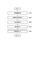
- FIG. 3 is a flowchart showing the contents of the first control process by the hydrogen production apparatus 1.
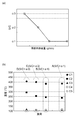
- FIG. 4 is an example of a control map used in the control amount setting process shown in FIG.
- FIG. 5 is a flowchart showing the second control process by the hydrogen production apparatus 1.
- the control processing shown in FIGS. 3 and 5 is repeatedly executed at a predetermined timing in the control unit 150. As will be described later, the control unit 150 may perform the first control process and the second control process in combination, or may perform only one of them.
- the first control process shown in FIG. 3 is a control that keeps the position of the water surface WF constant by changing the set value of the S / C to an optimal value using a control map according to the load fluctuation of the cell stack 20. is there.
- the control unit 150 executes a load information acquisition process for acquiring a load command from the load detection sensor CE to the cell stack 20 (step S10).
- the control unit 150 executes a raw fuel supply amount setting process for setting the supply amount of the raw fuel to be supplied to the reforming unit 6 in accordance with the load command to the cell stack 20 acquired in S10 (step S20). ).
- control unit 150 sets the raw fuel supply amount to be larger as the load on the cell stack 20 is larger, and sets the raw fuel supply amount to be smaller as the load on the cell stack 20 is smaller.
- the control unit 150 can set the raw fuel supply amount by calculating in consideration of the hydrogen utilization rate based on the target current value set according to the load command to the cell stack 20.
- control unit 150 executes a control amount setting process for setting a control amount so that the water surface WF becomes constant (step S30).
- the control amount is the amount of water supplied by the water supply pump 120.
- the control unit 150 calculates S / C corresponding to the raw fuel supply amount (that is, the load of the cell stack 20) using a control map stored in advance, and supplies water based on the calculated S / C. Set the amount.
- control map used in S30 will be described.
- the raw fuel supply amount (g / min) is set on the horizontal axis
- S / C is set on the vertical axis.
- the S / C is set to a constant value when the set raw fuel supply amount is a predetermined value or more, and as the set raw fuel supply amount becomes smaller than the predetermined value. A large value is set.
- the control map used in S30 is preset by an experiment using the temperature sensors C1, C2, C3, C4, and C5 at the time of manufacture.
- the value of S / C that can maintain the position of the water surface WF between the temperature sensor C2 and the temperature sensor C3 is obtained. That is, in a state where the load of the cell stack 20 is set to a predetermined value, the temperature sensors C1 and C2 maintain the state of continuously detecting the temperature of the water vapor, and the temperature sensors C3, C4 and C5 detect the temperature of the water. A value of S / C that can maintain the state of continuing is obtained.
- the temperature sensors C1 and C2 detect the temperature of water vapor at 100 ° C. or higher by setting S / C to ⁇ 1, as shown in A in the figure.
- the control unit 150 acquires the optimum S / C setting value using the raw fuel supply amount and the control map set in S20. Furthermore, the control unit 150 sets a water supply amount by the water supply pump 120 based on the acquired S / C. Next, the control unit 150 outputs a control signal to the raw fuel supply pump 110 and the water supply pump 120 so as to obtain the raw fuel supply amount set in S20 and the water supply amount set in S30. An output process is executed (step S40). As a result, the position of the water surface WF is maintained between the temperature sensor C2 and the temperature sensor C3 disposed above the upper end A8a of the selective oxidation catalyst layer A8 during the experiment.
- control unit 150 executes a raw fuel supply amount setting process for setting the supply amount of the raw fuel to be supplied to the reforming unit 6 in accordance with the load command to the cell stack 20 acquired in S10 (step S20). ).
- the control unit 150 sets the raw fuel supply amount to be larger as the load on the cell stack 20 is larger, and sets the raw fuel supply amount to be smaller as the load on the cell stack 20 is smaller.
- the control part 150 performs the water surface position acquisition process which acquires the position of the water surface WF based on the detection result of temperature sensor C1, C2, C3, C4, C5 (step S60).
- the control unit 150 executes a control amount setting process for setting a control amount so that the position of the water surface WF is constant (step S70).
- the control amount is the amount of water supplied by the water supply pump 120.
- the controller 150 increases the set value of S / C to increase the water surface WF. In this way, the water supply amount is set.
- the water surface WF rises to the position of the temperature sensor C2 (that is, when the temperature sensor C2 detects a temperature near 100 ° C.
- the control unit 150 reduces the set value of S / C to reduce the water surface.
- the water supply amount is set so that the WF is lowered.
- the control unit 150 outputs a control signal to the raw fuel supply pump 110 and the water supply pump 120 so as to obtain the raw fuel supply amount and the water supply amount set in S20 and S70. Is executed (step S80).
- the position of the water surface WF is maintained between the temperature sensor C2 and the temperature sensor C3 disposed above the upper end A8a of the selective oxidation catalyst layer A8. That is, the position of the water surface WF is constant above the upper end A8a of the selective oxidation catalyst layer A8.
- the control unit 150 acquires a load command to the cell stack 20 that generates power with the reformed gas, and changes the S / C based on the acquired load command. Can be made. That is, the control unit 150 can always set the optimum S / C by performing the map control according to the load fluctuation of the cell stack 20. Thereby, when the load becomes small, the position of the water surface WF can be adjusted in real time by following the load fluctuation by suppressing the decrease in the water surface WF by increasing the water vapor ratio. Therefore, the position of the water surface WF can be made constant and the evaporation vibration due to the water surface change during load fluctuation can be more reliably suppressed.
- FIG. 6 is a diagram illustrating a configuration of a hydrogen production apparatus 201 and a fuel cell system 200 according to a modification.
- the inner cylinder evaporating section 22 (9), the low temperature shift reaction section 13, the exhaust gas flow path L 1, and the outer cylinder evaporating section 21 (9) in the portion from the center in the axis G direction to the lower end of the main body 3.
- the selective oxidation reaction part 8 is arrange
- the outer cylinder evaporation part 21 is provided between the exhaust gas flow path L1 and the selective oxidation reaction part 8 so as to surround the exhaust gas flow path L1. Specifically, the outer cylinder evaporating section 21 is disposed adjacent to these on the radially outer side of the exhaust gas passage L1 and on the radially inner side of the selective oxidation reaction section 8.
- the outer cylinder evaporating unit 21 stores water introduced from the outside and vaporizes the stored water using ambient heat (that is, by heat moved from the surroundings) to generate water vapor. . Then, the outer cylinder evaporating unit 21 supplies the generated water vapor to the inner cylinder evaporating unit 22.
- an introduction part 21a for introducing (inflowing) water from the outside is provided, and at the upper end part, deriving (outflowing) water to the inner cylinder evaporating part 22 A portion 21b is provided.
- the inner cylinder evaporating unit 22 is provided so as to be surrounded by the low temperature shift reaction unit 13. Specifically, the inner cylinder evaporating unit 22 is disposed adjacent to the radially inner side of the low temperature shift reaction unit 13. The inner cylinder evaporating unit 22 further vaporizes the water vapor introduced from the outer cylinder evaporating unit 21 by further heating using ambient heat. Then, the inner cylinder evaporating unit 22 supplies the heated water vapor to the feed unit 5.
- the lower end portion of the inner cylinder evaporating portion 22 is provided with an introduction portion 22a for introducing water vapor from the outer tube evaporating portion 21, and the upper end portion is provided with a lead-out portion 22b for deriving water vapor to the feed portion 5. It has been.
- the exhaust gas flowing through the exhaust gas flow path L1 is cooled so as to be sandwiched from the outside and the inside by the evaporation units 21 and 22, and the exhaust gas is cooled. Is done. Therefore, the efficiency of the hydrogen production apparatus 201 can be improved.
- the low temperature shift reaction unit 13 is maintained at an appropriate temperature by the inner cylinder evaporation unit 22.
- the selective oxidation reaction unit 8 is cooled by the outer cylinder evaporation unit 21. Therefore, the temperatures of the low temperature shift reaction unit 13 and the selective oxidation reaction unit 8 can be accurately controlled.
- the selective oxidation reaction part 8 can be reliably controlled.
- the exhaust gas flowing through the exhaust gas passage L1 and the heat from the selective oxidation reaction section 8 are suitably used to heat water and generate water vapor.
- the exhaust gas flowing through the exhaust gas flow path L1 and the heat of the low temperature shift reaction section 13 are suitably used to further heat the steam. Therefore, water can be reliably vaporized to generate water vapor, and the vaporized state of water vapor can be stabilized. Therefore, according to the configuration of FIG. 6, it is possible to improve the performance of the hydrogen production apparatus 201, and thus improve the performance of the fuel cell system 200.
- the said embodiment is equipped with the high temperature shift reaction part 12 and the low temperature shift reaction part 13 as what carries out the shift reaction of the carbon monoxide in reformed gas, only the low temperature shift reaction part 13 is shown in FIG. You may have.
- the temperature sensor is used as the water surface position detecting means.
- a liquid level sensor that detects the liquid level by changing the refractive index using laser light or the like may be used.
- tubular shape includes not only a substantially cylindrical shape but also a substantially polygonal tubular shape.
- substantially cylindrical shape and the substantially polygonal cylindrical shape mean a cylindrical shape and a polygonal cylindrical shape in a broad sense such as those substantially equal to the cylindrical shape and the polygonal cylindrical shape, and those including at least a cylindrical shape and a polygonal cylindrical shape. ing.
- the present invention can be used for a hydrogen production apparatus and a fuel cell system.
Landscapes
- Chemical & Material Sciences (AREA)
- Chemical Kinetics & Catalysis (AREA)
- Organic Chemistry (AREA)
- Engineering & Computer Science (AREA)
- Inorganic Chemistry (AREA)
- Combustion & Propulsion (AREA)
- Sustainable Energy (AREA)
- Electrochemistry (AREA)
- General Chemical & Material Sciences (AREA)
- Health & Medical Sciences (AREA)
- General Health & Medical Sciences (AREA)
- Life Sciences & Earth Sciences (AREA)
- Sustainable Development (AREA)
- Manufacturing & Machinery (AREA)
- Fuel Cell (AREA)
- Hydrogen, Water And Hydrids (AREA)
Abstract
水素製造装置1は、原燃料を改質することにより水素を含有する改質ガスを生成する改質部6と、改質部6を加熱するバーナ10と、水を貯留すると共に、少なくともバーナ10の排ガスの熱によって水蒸気を生成する蒸発部9と、改質部6に供給される原燃料の量と改質部6に供給される水蒸気の量との比率を変化させることによって、蒸発部9内での位置が一定となるように水の水面の位置を調整する制御部150と、を備える。
Description
本発明は、水素製造装置及び燃料電池システムに関する。
従来の水素製造装置及び燃料電池システムは、炭化水素等の原燃料を改質することによって水素を含有する改質ガスを生成し、当該改質ガスによって燃料電池スタックで発電するものが知られていた(例えば、特許文献1参照)。このような燃料電池システムにおける水素製造装置は、改質反応に用いるバーナの排ガスを流通させる筒状の排ガス流路を筒状の蒸発部で取り囲む構造を有しており、蒸発部は水を貯留すると共に排ガスの熱によって当該水を蒸発させて改質部へ水蒸気を供給している。
ここで、上述したような燃料電池システムでは、一般的に、改質部に原燃料中のカーボンに対する水蒸気の量のモル比率を示すS/C(Steam to Carbon ratio)を一定の値にしてシステムの制御が行われていた。しかしながら、燃料電池システムに要求される電力の量(すなわち、電力を消費する電気機器の使用状況)は、システム運転中も変動しており、燃料電池スタックの負荷も変動する。このように負荷変動が生じた場合、蒸発部内の水の水面(水層とスチーム層との境界)が変動し、これによって水の蒸発振動が生じ改質ガスの流量が安定しないという問題が生じていた。
そこで、本発明は、安定して改質ガスを生成することができる水素製造装置及び燃料電池システムを提供することを目的とする。
水素製造装置は、原燃料を改質することにより水素を含有する改質ガスを生成する改質部と、改質部を加熱するバーナと、水を貯留すると共に、少なくともバーナの排ガスの熱によって水蒸気を生成する蒸発部と、改質部に供給される原燃料の量と改質部に供給される水蒸気の量との比率を変化させることによって、蒸発部内での位置が一定となるように水の水面の位置を調整する制御部と、を備える。
水素製造装置によれば、蒸発部は、水が貯留されると共に装置内の熱を回収することで水蒸気を生成し、当該水蒸気を改質部へ供給するものである。従って、燃料電池スタックの負荷が変動することによって、蒸発部内の水面の位置が変動する可能性がある。しかしながら、制御部は、改質部に供給される原燃料の量と改質部に供給される水蒸気の量との比率(例えば、S/C)を変化させて、水面の位置を一定とすることができる。これによって、負荷変動中の水面変化による蒸発振動を抑制することが可能となり、安定して改質ガスを生成することができる。
また、水素製造装置は、蒸発部に隣り合うように並設されると共に、改質部によって生成された改質ガス中の一酸化炭素を選択酸化触媒層によって選択酸化する選択酸化反応部を更に備え、制御部は、水面の位置が選択酸化触媒層の上端よりも上側となるように、水面の位置を調整してもよい。選択酸化反応部が蒸発部に隣り合うように並設されているため、選択酸化触媒層は蒸発部によって冷却されることが可能となり、蒸発部は選択酸化触媒層から熱を回収することが可能となる。ここで、蒸発部中の水面の位置が選択酸化触媒層の上端より低くなると、選択酸化触媒層の上端付近における冷却が不十分となる。これによって、選択酸化触媒層の温度が上昇し、発熱反応であるメタン化反応が過剰に進む可能性がある。メタン化反応が過剰に進行すると、温度が急上昇し、触媒や部材の耐熱温度を超える可能性がある。しかしながら、制御部は、水面の位置が選択酸化触媒層の上端よりも上側となるように水面の位置を調整することができるため、選択酸化触媒層の温度の急上昇を確実に防止することができる。
また、水素製造装置において、制御部は、改質ガスによって発電を行う燃料電池スタックへの負荷指令を取得すると共に、取得した負荷指令に基づいて、原燃料の量と水蒸気の量との比率を変化させてもよい。これによって、負荷が小さくなった場合に水蒸気の比率を大きくすることで水面の下降を抑制することにより、負荷変動に追従してリアルタイムに水面の位置を調整することができる。従って、水面の位置を確実に一定とすることができ、負荷変動中の水面変化による蒸発振動をより確実に抑制することが可能となる。
また、水素製造装置において、蒸発部に設けられ、水面の位置を検出する水面位置検出手段を更に備え、制御部は、水面検出手段によって検出された水面の位置に基づいて、原燃料の量と水蒸気の量との比率を変化させてもよい。このように、蒸発部内の水面の位置を直接検出して制御を行うことによって、実際の水面の位置に対応した水面調整を行うことができる。従って、一層確実に水面を一定に保つことが可能となる。
また、燃料電池システムは、上記水素製造装置と、水素製造装置によって生成された改質ガスを用いて発電を行う燃料電池スタックと、を備える。
この燃料電池システムにおいても、上記水素製造装置を備えているため、安定して改質ガスを生成することができるという上記効果が奏される。
本発明によれば、安定して改質ガスを生成することが可能となる。
以下、図面を参照しながら、好適な実施形態について詳細に説明する。なお、以下の説明では、同一又は相当要素には同一符号を付し、重複する説明は省略する。また、「上」「下」の語は、図面の上下方向に対応するものであり便宜的なものである。
図1は、実施形態に係る燃料電池システムの一部を示す概略ブロック図である。図1に示すように、水素製造装置(FPS:Fuel Processing System)1は、例えば家庭用の燃料電池システム100において水素供給源として利用されるものである。ここでの水素製造装置1は、原燃料として石油系炭化水素が用いられ、水素を含有する改質ガスをセルスタック(燃料電池スタック)20に供給する。
なお、原燃料としては、アルコール類、エーテル類、バイオ燃料、天然ガス、都市ガスを用いてもよい。また、石油系炭化水素としては、灯油、LPガスのほか、ナフサ、軽油などを原燃料として使用することができる。また、セルスタック20としては、固体高分子形、アルカリ電解質形、リン酸形、溶融炭酸塩形或いは固体酸化物形等の種々のものを用いてもよい。
図2は、図1の水素製造装置を示す概略正面端面図である。図1,2に示すように、水素製造装置1は、中心軸を軸Gとする円筒状外形の脱硫部2と、中心軸を軸Gとする円柱状外形の本体部3と、を備え、これらが筐体4に収容されている。また、筐体4内において脱硫部2及び本体部3の周囲には、粉状の断熱材(不図示)が充填されて断熱されている。脱硫部2は筐体4の外に設置されてもよい。
脱硫部2は、外部から導入された原燃料を脱硫触媒によって脱硫して硫黄分を除去し、この原燃料を後述のフィード部5へ供給する。脱硫部2は、筐体4の側板4xにパイプで固定され、本体部3の上部を所定の隙間を有して囲繞するよう保持されている。本体部3は、フィード部5、改質部6、シフト反応部7、選択酸化反応部8及び蒸発部9を備え、これらが一体で構成されている。この本体部3は、筐体4の床板4yに筒状のステーにより固定され保持されている。
フィード部5は、脱硫部2で脱硫した原燃料及び水蒸気(スチーム)を混合し、これらを改質部6に供給する。具体的には、フィード部5は、原燃料及び水蒸気を合流・混合させて混合ガス(混合流体)を生成する混合部5xと、混合ガスを改質部6へ流通させる混合ガス流路5yと、を含んでいる。
改質部(SR:Steam Reforming)6は、フィード部5により供給された混合ガスを改質触媒6xによって水蒸気改質して改質ガスを生成し、この改質ガスをシフト反応部7へ供給する。改質部6は、中心軸を軸Gとする円筒状外形を呈し、脱硫部2の筒内に位置するよう本体部3の上端側に設けられている。この改質部6にあっては、水蒸気改質反応が高温を必要としかつ吸熱反応であるため、改質部6の改質触媒6xを加熱するための熱源としてバーナ10を利用している。
バーナ10では、外部から原燃料がバーナ燃料として供給されて燃焼される。このバーナ10は、本体部3の上端部に設けられ軸Gを中心軸とする燃焼筒11に、バーナ10による火炎が取り囲まれるよう取り付けられている。なお、バーナ10においては、脱硫部2で脱硫した原燃料の一部が、バーナ燃料として供給されて燃焼される場合もある。
シフト反応部7は、改質部6から供給された改質ガスの一酸化炭素濃度(CO濃度)を低下させるためのものであり、改質ガス中の一酸化炭素をシフト反応させて水素及び二酸化炭素に転換する。ここでのシフト反応部7は、シフト反応を2段階に分けて行うことも可能であり、高温(例えば400°C~600°C)でのシフト反応である高温シフト反応を行う高温シフト反応部(HTS:High Temperature Shift)12と、高温シフト反応の温度よりも低温(例えば150°C~350°C)でのシフト反応である低温シフト反応を行う低温シフト反応部(LTS:LowTemperature Shift)13と、を有している。ただし、高温シフト反応部12は、必ずしも設けなくともよい。
高温シフト反応部12は、改質部6から供給された改質ガス中の一酸化炭素を高温シフト触媒12xによって高温シフト反応させ、改質ガスのCO濃度を低下させる。高温シフト反応部12は、中心軸を軸Gとする円筒状外形を呈しており、高温シフト触媒12xが改質触媒6xの下端部を囲繞するよう改質部6の径方向外側に隣接配置されている。この高温シフト反応部12は、CO濃度を低下させた改質ガスを低温シフト反応部13へ供給する。
低温シフト反応部13は、高温シフト反応部12で高温シフト反応させた改質ガス中の一酸化炭素を低温シフト触媒13xによって低温シフト反応させ、改質ガスのCO濃度を低下させる。低温シフト反応部13は、中心軸を軸Gとする円筒状外形を呈しており、本体部3の下端側に配設されている。この低温シフト反応部13は、CO濃度を低下させた改質ガスを改質ガス配管14xを介して選択酸化反応部8へ供給する。
選択酸化反応部(PROX:Preferential Oxidation)8は、低温シフト反応部13で低温シフト反応させた改質ガス中のCO濃度をさらに低下させる。これは、セルスタック20に高濃度の一酸化炭素を供給すると、セルスタック20の触媒が被毒して大きく性能低下するためである。この選択酸化反応部8は、具体的には、改質ガス中の一酸化炭素と空気配管15を介して導入される空気とを選択酸化触媒8xで反応させて、改質ガス中の水素を酸化させることなく、一酸化炭素を選択的に酸化し、二酸化炭素に転換する。選択酸化反応部8は、中心軸を軸Gとする円筒状外形を呈しており、本体部3の下端から所定長上端側に該本体部3の最外周側を構成するよう配設されている。
この選択酸化反応部8は、CO濃度をさらに低下させた改質ガスを、熱交換部16が設けられた改質ガス配管14yを介して外部へ導出する。熱交換部16は、改質ガス配管14y内を流通する改質ガスと、外部から水配管17xを介して導入された水との間で熱交換を行うと共に、この水を蒸発部9に水配管17yを介して供給する。
蒸発部9は、熱交換部16から供給された水を内部に貯留させると共に、この水をバーナ10からの排ガスによる熱、低温シフト反応部13及び選択酸化反応部8から移動させた(低温シフト反応部13及び選択酸化反応部8を冷却して得た)熱で気化させて水蒸気を生成する。蒸発部9は、ジャケット型のものであり、中心軸を軸Gとする円筒状を呈している。この蒸発部9は、高温シフト反応部12及び低温シフト反応部13の径方向外側で且つ選択酸化反応部8の径方向内側(つまり、シフト反応部7と選択酸化反応部8との間)に位置するよう配設されている。この蒸発部9は、生成した水蒸気をフィード部5の混合部5xに水蒸気配管17zを介して供給する。
このような水素製造装置1では、まず、バーナ燃料及びセルスタック20からのオフガス(セルスタック20で反応に使用されない残ガス)の少なくとも一方と空気とがバーナ10に供給されて燃焼され、かかる燃焼によって改質触媒6xが加熱される。そして、バーナ10の排ガスが排ガス流路L1及びガス配管18を流通して外部へ排気される。
これと共に、脱硫部2で脱硫された原燃料と蒸発部9からの水蒸気とが混合部5xで混合され、混合ガスが生成される。この混合ガスは、混合ガス流路5yを介して改質部6に供給されて改質触媒6xで水蒸気改質され、これにより、改質ガスが生成される。そして、生成された改質ガスは、シフト反応部7によってその一酸化炭素濃度が例えば数千ppm程度まで低下され、選択酸化反応部8によってその一酸化炭素濃度が10ppm程度以下まで低下された後、熱交換部16で冷却され、後段のセルスタック20へ導出される。
なお、本実施形態においては、例えば各触媒6x,12x,13x,8xにて触媒反応を好適に行うため、次のように各部位の温度が設定されている。すなわち、改質部6に流入する混合ガスの温度が約300~550℃とされ、改質部6から流出する改質ガスの温度が550℃~800℃とされ、高温シフト反応部12に流入する改質ガスの温度が400℃~600℃とされ、高温シフト反応部12から流出する改質ガスの温度が300℃~500℃とされている。また、低温シフト反応部13に流入する改質ガスの温度が150℃~350℃とされ、低温シフト反応部13から流出する改質ガスの温度が150℃~250℃とされ、選択酸化反応部8に流入する改質ガスの温度が90℃~210℃(120℃~190℃)とされている。
更に、本実施形態に係る燃料電池システム100及び水素製造装置1は、蒸発部9内に貯留された水の水面WFの位置を一定にする機能を有している。また、燃料電池システム100及び水素製造装置1は、水面WFの位置を調整し、当該水面WFの位置を選択酸化反応部8の選択酸化触媒層A8の上端A8aよりも上側とする機能を有している。なお、水面WFは、蒸発部9内の水が水蒸気となる境界部分である。ここでの「水面WFの位置が一定」とは、水面WFの位置に全く変動がない状況のみならず、水素製造装置1の性能に影響を及ぼさない限りにおいて所定の範囲内(例えば温度センサC2と温度センサC3との間の範囲)で変動する状況も含んでいる。このような機能を実現するため、燃料電池システム100は、負荷検出センサCEを更に備えている。また、水素製造装置1は、原燃料供給ポンプ110、水供給ポンプ120、バーナ燃料供給ポンプ130、バーナ空気供給ポンプ140、温度センサC1,C2,C3,C4,C5、制御部150を更に備えている。
負荷検出センサCEは、セルスタック20への負荷指令を検出する機能を有している。セルスタック20の負荷とは、セルスタック20に要求される電力量(W)であり、例えば、家庭内で使用される電気機器の使用状況によって変動する。使用される電気機器での消費電力が大きくなると、セルスタック20の負荷は大きくなる。一方、使用される電気機器での消費電力が小さくなると、セルスタック20の負荷は小さくなる。負荷検出センサCEは、制御部150と電気的に接続されており、検出結果を制御部150へ出力する(なお、図においては、一部の電気的な接続関係を省略している)。
原燃料供給ポンプ110は、改質部6へ原燃料を供給するポンプである。水供給ポンプ120は、水配管17xを介して蒸発部9へ水を供給するポンプである。バーナ燃料供給ポンプ130は、バーナ10にバーナ燃料を供給するポンプである。空気供給ポンプ140は、バーナ10に空気を供給するポンプである。各ポンプは、制御部150と電気的に接続されており、制御部150から入力された制御信号に基づいて駆動する。なお、各ポンプの配置は、図1及び図2に示す位置に限定されない。
温度センサC1,C2,C3,C4,C5は、水蒸気配管17z、または蒸発部9内の温度を検出することによって、水面WFの位置を検出するセンサである。温度センサC1は、蒸発部9の上端側に接続された水蒸気配管17zの接続部EP付近に設けられている。これによって、温度センサC1は、蒸発部9からフィード部5へ向かう水蒸気の温度を検出することができる。温度センサC2,C3,C4,C5は、上から下へ向かってこの順番で蒸発部9の内部に設けられている。温度センサC2及び温度センサC3は、高さ方向において、接続部EPと選択酸化触媒層A8の上端A8aとの間に配置されている。温度センサC4及び温度センサC5は、高さ方向において、選択酸化触媒層A8の上端A8aと下端A8bとの間に配置されている。なお、選択酸化触媒層A8は、上端A8aから下端A8bの全領域にわたって蒸発部9に冷却されるように、当該蒸発部9と隣り合うように並設されている。ここで、選択酸化反応部8は、蒸発部9の外周面に直接取り付けられることによって当該蒸発部9と隣り合うように並設される構成であってもよく、間に流路や空隙などの空間を挟んで当該蒸発部9と隣り合う構成であってもよく、蒸発部9によって選択酸化触媒層A8が冷却されることが可能な配置であれば特に限定されない。温度センサC1,C2,C3,C4,C5のうち、水面WFよりも上側に配置されているものは、水蒸気の温度を検出するため、100℃よりも大幅に高い温度を検出する。一方、温度センサC1,C2,C3,C4,C5のうち、水面WFよりも下側に配置されているものは、水の温度を検出するため、100℃以下あるいは100℃付近の温度を検出する。これによって、温度センサC1,C2,C3,C4,C5は、各センサの検出値に基づいて水面WFの位置を検出することができる。例えば、温度センサC2が高温を検出し、温度センサC3が100℃付近の温度を検出した場合、水面WFの位置は、温度センサC2と温度センサC3との間であると検出される(図4(b)参照)。なお、蒸発部9内において選択酸化触媒層A8の上端A8aよりも上側に配置される温度センサC2と温度センサC3が少なくとも設けられていればよく、温度センサC4,C5は設けなくともよい。また、後述の第一制御処理のみを行う場合は、温度センサC1,C2,C3,C4,C5は設けられていなくてもよい。
制御部150は、水素製造装置1全体の制御を行う機能を有しており、例えば電子制御を行うデバイス(例えばCPU(Central Processing Unit)、ROM(Read Only Memory)、RAM(Random Access Memory)、および入出力インターフェイスを含んで構成されたデバイス)によって構成されている。制御部150は、各ポンプを制御することによって、蒸発部9内の水面WFの位置が一定に保たれるように調整する機能を有している。制御部150は、当該水面WFの位置が選択酸化反応部8の選択酸化触媒層A8の上端A8aよりも上側となるように、水面WFの位置を調整する。具体的に、制御部150は、セルスタック20の負荷に基づいて、改質部6に供給される原燃料の量、及び改質部6に供給される水蒸気の量を制御することによって、水面WFの位置を調整する。すなわち、制御部150は、セルスタック20の負荷変動に応じて変化させながら最適なS/Cを設定し、設定したS/Cが得られるように水供給ポンプ120を駆動させることによって、水面WFの位置を調整する。制御部150は、原燃料供給ポンプ110へ原燃料供給量の設定値に応じた制御信号を出力することで、改質部6へ供給される原燃料の量を制御することができる。また、制御部150は、水供給ポンプ120へ水供給量の設定値に応じた制御信号を出力することで、改質部6へ供給される水蒸気の量を制御することができる。なお、S/Cとは、改質部6に供給される原燃料中のカーボンに対する、改質部6に供給される水蒸気のモル比率である。また、制御部150は、温度センサC1,C2,C3,C4,C5を用いて検出した水面WFの位置に基づいて、S/Cを変化させることによって、水面WFの位置を調整する。
次に、図2、図3、図4及び図5を参照して、本実施形態に係る水素製造装置1による制御処理について説明する。図3は、水素製造装置1による第一制御処理の内容を示すフローチャートである。図4は、図3に示す制御量設定処理において用いられる制御マップの一例である。図5は、水素製造装置1による第二制御処理を示すフローチャートである。図3及び図5に示す制御処理は、制御部150内において所定のタイミングで繰り返し実行される。なお、後述するように、制御部150は、第一制御処理及び第二制御処理を組み合わせて行ってもよく、あるいはいずれか一方のみを行ってもよい。
[第一制御処理]
図3に示す第一制御処理は、セルスタック20の負荷変動に応じて制御マップを用いてS/Cの設定値を最適な値に変更することで、水面WFの位置を一定に保つ制御である。図3に示すように、制御部150は、負荷検出センサCEからセルスタック20への負荷指令を取得する負荷情報取得処理を実行する(ステップS10)。次に、制御部150は、S10で取得したセルスタック20への負荷指令に応じ、改質部6に供給すべき原燃料の供給量を設定する原燃料供給量設定処理を実行する(ステップS20)。S20において、制御部150は、セルスタック20の負荷が大きいほど、原燃料供給量を多く設定し、セルスタック20の負荷が小さいほど、原燃料供給量を少なく設定する。制御部150は、セルスタック20への負荷指令に応じて設定される目標電流値に基づき、水素利用率等を考慮して演算することによって、原燃料供給量を設定することができる。
図3に示す第一制御処理は、セルスタック20の負荷変動に応じて制御マップを用いてS/Cの設定値を最適な値に変更することで、水面WFの位置を一定に保つ制御である。図3に示すように、制御部150は、負荷検出センサCEからセルスタック20への負荷指令を取得する負荷情報取得処理を実行する(ステップS10)。次に、制御部150は、S10で取得したセルスタック20への負荷指令に応じ、改質部6に供給すべき原燃料の供給量を設定する原燃料供給量設定処理を実行する(ステップS20)。S20において、制御部150は、セルスタック20の負荷が大きいほど、原燃料供給量を多く設定し、セルスタック20の負荷が小さいほど、原燃料供給量を少なく設定する。制御部150は、セルスタック20への負荷指令に応じて設定される目標電流値に基づき、水素利用率等を考慮して演算することによって、原燃料供給量を設定することができる。
次に、制御部150は、水面WFが一定となるように、制御量を設定する制御量設定処理を実行する(ステップS30)。S30において、制御量とは水供給ポンプ120による水の供給量である。S30において、制御部150は、予め記憶している制御マップを用いて原燃料供給量(すなわちセルスタック20の負荷)に応じたS/Cを算出し、算出したS/Cに基づいて水供給量を設定する。
ここで、S30において用いられる制御マップについて説明する。S30の処理において用いられる制御マップとして、例えば図4(a)に示すものが挙げられる。この制御マップは、横軸に原燃料供給量(g/min)が設定され、縦軸にS/Cが設定されている。図4(a)に示すように、S/Cは、設定される原燃料供給量が所定値以上の場合は一定の値に設定され、設定される原燃料供給量が所定値より小さくなるに従って大きな値が設定される。S30で用いられる制御マップは、製造時において温度センサC1,C2,C3,C4,C5を用いた実験によって予め設定される。この実験では、セルスタック20の負荷が所定の値の場合において、水面WFの位置を温度センサC2と温度センサC3との間で維持できるようなS/Cの値が求められる。すなわち、セルスタック20の負荷を所定の値に設定した状態において、温度センサC1,C2が水蒸気の温度を検出し続けている状態を維持し、温度センサC3,C4,C5が水の温度を検出し続けている状態を維持できるようなS/Cの値を求める。図4(b)に示す例では、負荷が大きい場合は、図中Aに示すように、S/Cをα1に設定することで、温度センサC1,C2が水蒸気の100℃以上の温度を検出する状態を維持し、温度センサC3,C4,C5が水の100℃付近の温度を検出する状態を維持できる。また、負荷をAよりも小さくした場合は、図中Bに示すように、S/Cはα1のままでも、温度センサC1,C2が水蒸気の100℃以上の温度を検出する状態を維持し、温度センサC3,C4,C5が水の100℃付近の温度を検出する状態を維持することができる。負荷を更に小さくした場合は、図中Cに示すように、S/Cを大きくしてα2に設定することで、温度センサC1,C2が水蒸気の100℃以上の温度を検出する状態を維持し、温度センサC3,C4,C5が水の100℃付近の温度を検出する状態を維持することができる。負荷を更に小さくした場合は、図中Dに示すように、S/Cを更に大きくしてα3に設定することで、温度センサC1,C2が水蒸気の100℃以上の温度を検出する状態を維持し、温度センサC3,C4,C5が水の100℃付近の温度を検出する状態を維持することができる。図4(b)の実験結果に基づいて、セルスタック20の負荷と適切なS/Cの設定値との関係が得られ、更に、図4(a)に示すような原燃料供給量と適切なS/Cの設定値との関係を示す制御マップが得られる。なお、実際の運転時に第一制御処理のみを行う場合は、温度センサC1,C2,C3,C4,C5は全て取り外してもよい。
図3に戻り、S30においては、制御部150は、S20で設定した原燃料供給量と制御マップとを用いて最適なS/Cの設定値を取得する。更に、制御部150は、取得したS/Cに基づいて、水供給ポンプ120による水供給量を設定する。次に、制御部150は、S20で設定した原燃料供給量とS30で設定した水供給量を得られるように、原燃料供給ポンプ110と水供給ポンプ120に対して制御信号を出力する制御信号出力処理を実行する(ステップS40)。これによって、水面WFの位置は、実験時に選択酸化触媒層A8の上端A8aよりも上側に配置されていた温度センサC2と温度センサC3との間で保たれる。すなわち、水面WFの位置は、選択酸化触媒層A8の上端A8aよりも上側で一定となる。S40の処理が終了すると図3に示す第一制御処理が終了し、再びS10から処理を開始する。なお、第一制御処理において、原燃料供給量とS/Cとの関係を設定した制御マップを用いたが、用いる制御マップはこれに限定されず、例えば、負荷とS/Cとの関係を設定した制御マップを用いてもよく、改質部6に供給される原燃料と水蒸気との比率、及びセルスタック20の負荷(あるいは負荷に対応する原燃料供給量)の関係を設定した制御マップであればどのようなものを用いてもよい。
[第二制御処理]
図5に示す第二制御処理は、温度センサC1、C2,C3,C4,C5を用いて水面WFの位置を検出し続け、水面WFが一定の位置より下がった場合(または上がった場合)にS/Cの設定値を最適な値に変更することで、水面WFの位置を一定に保つ制御である。ここでは、水面WFが温度センサC2と温度センサC3との間の位置に保たれるような制御が行われる。図5に示すように、制御部150は、負荷検出センサCEからセルスタック20への負荷指令を取得する負荷情報取得処理を実行する(ステップS10)。次に、制御部150は、S10で取得したセルスタック20への負荷指令に応じ、改質部6に供給すべき原燃料の供給量を設定する原燃料供給量設定処理を実行する(ステップS20)。S20において、制御部150は、セルスタック20の負荷が大きいほど、原燃料供給量を多く設定し、セルスタック20の負荷が小さいほど、原燃料供給量を少なく設定する。次に制御部150は、温度センサC1、C2,C3,C4,C5の検出結果に基づき、水面WFの位置を取得する水面位置取得処理を実行する(ステップS60)。次に、制御部150は、S60で取得した水面WFの位置に基づき、水面WFの位置が一定となるように制御量を設定する制御量設定処理を実行する(ステップS70)。S70において、制御量とは水供給ポンプ120による水の供給量である。S70において、制御部150は、水面WFが温度センサC3の位置まで下がった場合(すなわち、温度センサC3が高温な水蒸気を検出した場合)、S/Cの設定値を大きくして水面WFが上がるように、水供給量を設定する。一方、制御部150は、水面WFが温度センサC2の位置まで上がった場合(すなわち、温度センサC2が水の100℃付近の温度を検出した場合)、S/Cの設定値を小さくして水面WFが下がるように水供給量を設定する。次に、制御部150は、S20及びS70で設定した原燃料供給量及び水供給量を得られるように、原燃料供給ポンプ110と水供給ポンプ120に対して制御信号を出力する制御信号出力処理を実行する(ステップS80)。これによって、水面WFの位置は、選択酸化触媒層A8の上端A8aよりも上側に配置されている温度センサC2と温度センサC3との間で保たれる。すなわち、水面WFの位置は、選択酸化触媒層A8の上端A8aよりも上側で一定となる。S80の処理が終了すると図5に示す第二制御処理が終了し、再びS10から処理を開始する。
図5に示す第二制御処理は、温度センサC1、C2,C3,C4,C5を用いて水面WFの位置を検出し続け、水面WFが一定の位置より下がった場合(または上がった場合)にS/Cの設定値を最適な値に変更することで、水面WFの位置を一定に保つ制御である。ここでは、水面WFが温度センサC2と温度センサC3との間の位置に保たれるような制御が行われる。図5に示すように、制御部150は、負荷検出センサCEからセルスタック20への負荷指令を取得する負荷情報取得処理を実行する(ステップS10)。次に、制御部150は、S10で取得したセルスタック20への負荷指令に応じ、改質部6に供給すべき原燃料の供給量を設定する原燃料供給量設定処理を実行する(ステップS20)。S20において、制御部150は、セルスタック20の負荷が大きいほど、原燃料供給量を多く設定し、セルスタック20の負荷が小さいほど、原燃料供給量を少なく設定する。次に制御部150は、温度センサC1、C2,C3,C4,C5の検出結果に基づき、水面WFの位置を取得する水面位置取得処理を実行する(ステップS60)。次に、制御部150は、S60で取得した水面WFの位置に基づき、水面WFの位置が一定となるように制御量を設定する制御量設定処理を実行する(ステップS70)。S70において、制御量とは水供給ポンプ120による水の供給量である。S70において、制御部150は、水面WFが温度センサC3の位置まで下がった場合(すなわち、温度センサC3が高温な水蒸気を検出した場合)、S/Cの設定値を大きくして水面WFが上がるように、水供給量を設定する。一方、制御部150は、水面WFが温度センサC2の位置まで上がった場合(すなわち、温度センサC2が水の100℃付近の温度を検出した場合)、S/Cの設定値を小さくして水面WFが下がるように水供給量を設定する。次に、制御部150は、S20及びS70で設定した原燃料供給量及び水供給量を得られるように、原燃料供給ポンプ110と水供給ポンプ120に対して制御信号を出力する制御信号出力処理を実行する(ステップS80)。これによって、水面WFの位置は、選択酸化触媒層A8の上端A8aよりも上側に配置されている温度センサC2と温度センサC3との間で保たれる。すなわち、水面WFの位置は、選択酸化触媒層A8の上端A8aよりも上側で一定となる。S80の処理が終了すると図5に示す第二制御処理が終了し、再びS10から処理を開始する。
なお、制御部150は、上述の第一制御処理と第二制御処理のいずれか一方のみを行ってもよく、第一制御処理と第二制御処理を組み合わせた制御処理を行ってもよい。第一制御処理と第二制御処理を組み合わせた制御処理とは、例えば、水面WFが温度センサC2と温度センサC3との間の位置に保たれている状態では第一制御処理によって水面WFの位置を保ち、温度センサC2,C3が水面WFを検出したタイミングで第二制御処理に切り替えることができる。このとき、第二制御処理では、制御マップで設定される値よりもS/Cを大きい(あるいは小さい)値を設定する。これによって、通常時は制御マップに基づいて負荷変動に応じた制御をしつつも、何らかの理由で水面WFの位置が変動した場合は、制御マップを補助するように実際の水面WFに応じた制御をすることができる。または、水面WFが温度センサC2と温度センサC3との間に位置するときは、第二制御処理を行うことで温度センサC2,C3の温度を監視すると共にS/Cを一定値にして制御を行い、温度センサC2,C3が水面WFを検出したことをトリガーとして、第一制御処理に切り替えてもよい。これによって、通常時はS/Cを一定値にして制御することで演算の負荷を低減しつつも、負荷変動によって水面WFに変動があった場合には、負荷変動に応じた制御に切り替えることによって、確実に水面WFを一定にすることができる。
次に、本実施形態に係る水素製造装置1及び燃料電池システム100の作用・効果について説明する。
本実施形態に係る水素製造装置1によれば、蒸発部9は、水が貯留されると共に装置内の熱を回収することで水蒸気を生成し、当該水蒸気を改質部6へ供給するものである。従って、セルスタック20の負荷が変動することによって、蒸発部9内の水面WFの位置が変動する可能性がある。しかしながら、制御部150は、S/C(改質部6に供給される原燃料の量と改質部6に供給される水蒸気の量との比率)を変化させて、水面WFの位置を一定とすることができる。これによって、負荷変動中の水面変化による蒸発振動を抑制することが可能となり、安定して改質ガスを生成することができる。
また、本実施形態に係る水素製造装置1において、選択酸化反応部8が蒸発部9に隣り合うように並設されているため、選択酸化触媒層A8は蒸発部9によって冷却されることが可能となり、蒸発部9は選択酸化触媒層A8から熱を回収することが可能となる。ここで、蒸発部9中の水面WFの位置が選択酸化触媒層A8の上端A8aより低くなると、選択酸化触媒層A8の上端A8a付近における冷却が不十分となる。これによって、選択酸化触媒層A8の温度が上昇することにより、発熱反応であるメタン化反応が過剰に進む可能性がある。メタン化反応が過剰に進行すると、温度が急上昇し、触媒や部材の耐熱温度を超えることが懸念される。しかしながら、制御部150は、水面WFの位置が選択酸化触媒層A8の上端A8aよりも上側となるように水面WFの位置を調整することができるため、選択酸化触媒層A8の温度の急上昇を確実に防止することができる。
また、本実施形態に係る水素製造装置1において、制御部150は、改質ガスによって発電を行うセルスタック20への負荷指令を取得すると共に、取得した負荷指令に基づいて、S/Cを変化させることができる。すなわち、制御部150は、セルスタック20の負荷変動に応じてマップ制御を行うことによって、常に最適なS/Cを設定することができる。これによって、負荷が小さくなった場合は水蒸気の比率を大きくすることで水面WFの低下を抑制することにより、負荷変動に追従してリアルタイムに水面WFの位置を調整することができる。従って、水面WFの位置を確実に一定とすることができ、負荷変動中の水面変化による蒸発振動をより確実に抑制することが可能となる。
また、本実施形態に係る水素製造装置1において、蒸発部9に設けられ、水面WFの位置を検出することが可能な温度センサC1,C2,C3,C4,C5備え、制御部150は、温度センサC1,C2,C3,C4,C5によって検出された水面WFの位置に基づいて、S/Cを変化せることができる。このように、蒸発部9内の水面WFの位置を直接検出して制御を行うことによって、実際の水面WFの位置に対応した水面調整を行うことができる。従って、一層確実に水面WFを一定に保つことが可能となる。
以上、好適な実施形態について説明したが、本発明に係る水素製造装置及び燃料電池システムは、各実施形態に係る上記水素製造装置及び上記燃料電池システムに限られるものではなく、各請求項に記載した要旨を変更しない範囲で変形し、又は他のものに適用したものであってもよい。
例えば、上記実施形態で示された水素製造装置の構成は、一例であり、各構成要素の構成は特に限定されず、各流路や配管や構成要素の位置関係や構成を適宜変更してもよい。例えば、改質部6は、原燃料及び水蒸気を改質するものであればよく、構造が異なるものを採用してもよい。また、脱硫部2がなくともよい。
また、蒸発部9の構成は水を貯留すると共に装置の熱を回収するジャケットタイプのものであればその構成は特に限定されない。例えば、図6に示すような構造にしてもよい。図6は、変形例に係る水素製造装置201及び燃料電池システム200の構成を示す図である。水素製造装置201では、本体部3の軸G方向中央から下端部に亘る部分において、内筒蒸発部22(9)、低温シフト反応部13、排ガス流路L1、外筒蒸発部21(9)及び選択酸化反応部8が、径方向内側から外側に向かう方向にこの順で配置されている。
排ガス流路L1は、中心軸を軸Gとする円筒状外形を呈し、低温シフト反応部13を囲繞するように設けられている。排ガス流路L1は、低温シフト反応部13の径方向外側に隣接配置されている。この排ガス流路L1は、排気ガスを上方から下方に向けて(軸G方向の一方側から他方側)に流通させる。選択酸化反応部8は、排ガス流路L1を囲繞するように設けられており、排ガス流路L1の径方向外側に所定の隙間を有して配置されている。
外筒蒸発部21は、排ガス流路L1と選択酸化反応部8との間において排ガス流路L1を囲繞するように設けられている。具体的には、外筒蒸発部21は、排ガス流路L1の径方向外側で且つ選択酸化反応部8の径方向内側にて、これらに隣接配置されている。外筒蒸発部21は、外部から導入された水を内部に貯留させると共に、貯留させた水を周囲の熱を利用して(つまり、周囲から移動させた熱によって)気化させて水蒸気を生成する。そして、外筒蒸発部21は、生成した水蒸気を内筒蒸発部22へ供給する。この外筒蒸発部21の下端部には、水を外部から導入(流入)する導入部21aが設けられていると共に、上端部には、水を内筒蒸発部22へ導出(流出)する導出部21bが設けられている。
内筒蒸発部22は、低温シフト反応部13に囲繞されるように設けられている。具体的には、内筒蒸発部22は、低温シフト反応部13の径方向内側に隣接配置されている。内筒蒸発部22は、外筒蒸発部21から導入された水蒸気を、周囲の熱を利用してさらに加熱して完全に気化させる。そして、内筒蒸発部22は、加熱した水蒸気をフィード部5へ供給する。この内筒蒸発部22の下端部には、水蒸気を外筒蒸発部21から導入する導入部22aが設けられていると共に、上端部には、水蒸気をフィード部5へ導出する導出部22bが設けられている。
以上によって、図6に示す水素製造装置201及び燃料電池システム200によれば、排ガス流路L1を流通する排気ガスが蒸発部21,22によって外側及び内側から挟み込むよう冷却され、排気ガスが低温化される。よって、水素製造装置201の効率を向上させることができる。また、低温シフト反応部13が内筒蒸発部22によって適温に保たれる。さらに、選択酸化反応部8が、外筒蒸発部21によって冷却される。よって、これら低温シフト反応部13及び選択酸化反応部8の温度を、精度よくコントロールすることが可能となる。特に、外筒蒸発部21の温度を適温に保つことで、選択酸化反応部8に対し確実な温度コントロールを行うことができる。他方、外筒蒸発部21では、排ガス流路L1を流通する排ガス及び選択酸化反応部8からの熱が好適に利用されて水が加熱され、水蒸気が生成される。これと共に、内筒蒸発部22では、排ガス流路L1を流通する排ガス及び低温シフト反応部13の熱が好適に利用されて水蒸気がさらに加熱される。よって、水を確実に気化させて水蒸気を生成でき、且つ水蒸気の気化状態を安定化させることができる。従って、図6の構成によれば、水素製造装置201の性能向上、ひいては、燃料電池システム200の性能向上を実現することが可能となる。
また、上記実施形態は、改質ガス中の一酸化炭素をシフト反応させるものとして高温シフト反応部12及び低温シフト反応部13を備えているが、図6に示すように低温シフト反応部13のみ備えていてもよい。
また、上記実施形態では、水面位置検出手段として温度センサを用いていたが、レーザ光等を用い屈折率の変化で液面を検出する液面レベルセンサ等を用いてもよい。
ちなみに、上記の「筒状」とは、略円筒状だけでなく、略多角筒状を含むものである。また、略円筒状及び略多角筒状とは、円筒状及び多角筒状に概略等しいものや、円筒状及び多角筒状の部分を少なくとも含むもの等の広義の円筒状及び多角筒状を意味している。
本発明は、水素製造装置及び燃料電池システムに利用可能である。
1,201…水素製造装置、6…改質部、8…選択酸化反応部、A8…選択酸化触媒層、A8a…上端、9…蒸発部、10…バーナ、20…セルスタック(燃料電池スタック)、100,200…燃料電池システム、150…制御部、C1,C2,C3,C4,C5…温度センサ(水面位置検出手段)、WF…水面、G…軸。
Claims (5)
- 原燃料を改質することにより水素を含有する改質ガスを生成する改質部と、
前記改質部を加熱するバーナと、
水を貯留すると共に、少なくとも前記バーナの排ガスの熱によって水蒸気を生成する蒸発部と、
前記改質部に供給される前記原燃料の量と前記改質部に供給される前記水蒸気の量との比率を変化させることによって、前記蒸発部内での位置が一定となるように前記水の水面の位置を調整する制御部と、を備えることを特徴とする水素製造装置。 - 前記蒸発部に隣り合うように並設されると共に、前記改質部によって生成された前記改質ガス中の一酸化炭素を選択酸化触媒層によって選択酸化する選択酸化反応部を更に備え、
前記制御部は、前記水面の位置が前記選択酸化触媒層の上端よりも上側となるように、前記水面の位置を調整することを特徴とする請求項1記載の水素製造装置。 - 前記制御部は、前記改質ガスによって発電を行う燃料電池スタックへの負荷指令を取得すると共に、取得した前記負荷指令に基づいて、前記原燃料の量と前記水蒸気の量との比率を変化させることを特徴とする請求項1または2記載の水素製造装置。
- 前記蒸発部に設けられ、前記水面の位置を検出する水面位置検出手段を更に備え、
前記制御部は、前記水面検出手段によって検出された前記水面の位置に基づいて、前記原燃料の量と前記水蒸気の量との比率を変化させることを特徴とする請求項1~3のいずれか一項記載の水素製造装置。 - 請求項1~4の何れか一項記載の水素製造装置と、
前記水素製造装置によって生成した前記改質ガスを用いて発電を行う燃料電池スタックと、を備えたことを特徴とする燃料電池システム。
Applications Claiming Priority (2)
| Application Number | Priority Date | Filing Date | Title |
|---|---|---|---|
| JP2010078789A JP5597426B2 (ja) | 2010-03-30 | 2010-03-30 | 水素製造装置及び燃料電池システム |
| JP2010-078789 | 2010-03-30 |
Publications (1)
| Publication Number | Publication Date |
|---|---|
| WO2011122419A1 true WO2011122419A1 (ja) | 2011-10-06 |
Family
ID=44712129
Family Applications (1)
| Application Number | Title | Priority Date | Filing Date |
|---|---|---|---|
| PCT/JP2011/057014 Ceased WO2011122419A1 (ja) | 2010-03-30 | 2011-03-23 | 水素製造装置及び燃料電池システム |
Country Status (2)
| Country | Link |
|---|---|
| JP (1) | JP5597426B2 (ja) |
| WO (1) | WO2011122419A1 (ja) |
Families Citing this family (1)
| Publication number | Priority date | Publication date | Assignee | Title |
|---|---|---|---|---|
| JP7409971B2 (ja) * | 2020-06-05 | 2024-01-09 | 大阪瓦斯株式会社 | 固体酸化物形燃料電池システム |
Citations (2)
| Publication number | Priority date | Publication date | Assignee | Title |
|---|---|---|---|---|
| JP2004284901A (ja) * | 2003-03-24 | 2004-10-14 | Matsushita Electric Ind Co Ltd | 水素生成装置とそれを用いた燃料電池システム |
| JP2007269538A (ja) * | 2006-03-31 | 2007-10-18 | Aisin Seiki Co Ltd | 改質装置 |
-
2010
- 2010-03-30 JP JP2010078789A patent/JP5597426B2/ja not_active Expired - Fee Related
-
2011
- 2011-03-23 WO PCT/JP2011/057014 patent/WO2011122419A1/ja not_active Ceased
Patent Citations (2)
| Publication number | Priority date | Publication date | Assignee | Title |
|---|---|---|---|---|
| JP2004284901A (ja) * | 2003-03-24 | 2004-10-14 | Matsushita Electric Ind Co Ltd | 水素生成装置とそれを用いた燃料電池システム |
| JP2007269538A (ja) * | 2006-03-31 | 2007-10-18 | Aisin Seiki Co Ltd | 改質装置 |
Also Published As
| Publication number | Publication date |
|---|---|
| JP5597426B2 (ja) | 2014-10-01 |
| JP2011207706A (ja) | 2011-10-20 |
Similar Documents
| Publication | Publication Date | Title |
|---|---|---|
| EP2543627A1 (en) | Hydrogen generator and fuel cell power generation system | |
| US8709668B2 (en) | Hydrogen generation device and fuel cell system | |
| WO2011122579A1 (ja) | 水素製造装置及び燃料電池システム | |
| JP5600460B2 (ja) | 水素製造装置及び燃料電池システム | |
| JP5534900B2 (ja) | 水素製造装置及び燃料電池システム | |
| JP5597426B2 (ja) | 水素製造装置及び燃料電池システム | |
| JP5562700B2 (ja) | 水素製造装置及び燃料電池システム | |
| JPWO2006088018A1 (ja) | 水素生成装置及びその運転方法並びに燃料電池システム | |
| JP5117690B2 (ja) | 燃料電池システム | |
| JP5634729B2 (ja) | 水素製造装置及び燃料電池システム | |
| JP5162989B2 (ja) | 改質装置 | |
| JP5462687B2 (ja) | 水素製造装置及び燃料電池システム | |
| JP4902165B2 (ja) | 燃料電池用改質装置およびこの燃料電池用改質装置を備える燃料電池システム | |
| JP5513209B2 (ja) | 燃料電池システム及び燃料電池システムの制御方法 | |
| JP2011207728A (ja) | 水素製造装置及び燃料電池システム | |
| JP5613432B2 (ja) | 水素製造装置、燃料電池システム及び水素製造装置の起動方法 | |
| JP2008115058A (ja) | 燃料改質装置 | |
| JP2011207726A (ja) | 水素製造装置及び燃料電池システム | |
| JP5638822B2 (ja) | 燃料電池システム及び燃料電池システムの制御方法 | |
| JP2011210643A (ja) | 燃料電池システム及び燃料電池システムの制御方法 | |
| JP5538025B2 (ja) | 水素製造装置及び燃料電池システム | |
| JP2014009129A (ja) | 水素製造装置及び燃料電池システム | |
| JP5592760B2 (ja) | 燃料電池発電システム | |
| JP2009078938A (ja) | 脱硫器およびその運転方法、ならびに燃料電池システム | |
| JP2011207729A (ja) | 水素製造装置及び燃料電池システム |
Legal Events
| Date | Code | Title | Description |
|---|---|---|---|
| 121 | Ep: the epo has been informed by wipo that ep was designated in this application |
Ref document number: 11762651 Country of ref document: EP Kind code of ref document: A1 |
|
| NENP | Non-entry into the national phase |
Ref country code: DE |
|
| 122 | Ep: pct application non-entry in european phase |
Ref document number: 11762651 Country of ref document: EP Kind code of ref document: A1 |