WO2011122005A1 - 基板搬送機構および偏光フィルムの貼合装置における反転機構 - Google Patents
基板搬送機構および偏光フィルムの貼合装置における反転機構 Download PDFInfo
- Publication number
- WO2011122005A1 WO2011122005A1 PCT/JP2011/001869 JP2011001869W WO2011122005A1 WO 2011122005 A1 WO2011122005 A1 WO 2011122005A1 JP 2011001869 W JP2011001869 W JP 2011001869W WO 2011122005 A1 WO2011122005 A1 WO 2011122005A1
- Authority
- WO
- WIPO (PCT)
- Prior art keywords
- substrate
- reversing
- polarizing film
- transport mechanism
- unit
- Prior art date
- Legal status (The legal status is an assumption and is not a legal conclusion. Google has not performed a legal analysis and makes no representation as to the accuracy of the status listed.)
- Ceased
Links
Images



Classifications
-
- B—PERFORMING OPERATIONS; TRANSPORTING
- B65—CONVEYING; PACKING; STORING; HANDLING THIN OR FILAMENTARY MATERIAL
- B65G—TRANSPORT OR STORAGE DEVICES, e.g. CONVEYORS FOR LOADING OR TIPPING, SHOP CONVEYOR SYSTEMS OR PNEUMATIC TUBE CONVEYORS
- B65G49/00—Conveying systems characterised by their application for specified purposes not otherwise provided for
- B65G49/05—Conveying systems characterised by their application for specified purposes not otherwise provided for for fragile or damageable materials or articles
- B65G49/06—Conveying systems characterised by their application for specified purposes not otherwise provided for for fragile or damageable materials or articles for fragile sheets, e.g. glass
- B65G49/067—Sheet handling, means, e.g. manipulators, devices for turning or tilting sheet glass
-
- G—PHYSICS
- G02—OPTICS
- G02F—OPTICAL DEVICES OR ARRANGEMENTS FOR THE CONTROL OF LIGHT BY MODIFICATION OF THE OPTICAL PROPERTIES OF THE MEDIA OF THE ELEMENTS INVOLVED THEREIN; NON-LINEAR OPTICS; FREQUENCY-CHANGING OF LIGHT; OPTICAL LOGIC ELEMENTS; OPTICAL ANALOGUE/DIGITAL CONVERTERS
- G02F1/00—Devices or arrangements for the control of the intensity, colour, phase, polarisation or direction of light arriving from an independent light source, e.g. switching, gating or modulating; Non-linear optics
- G02F1/01—Devices or arrangements for the control of the intensity, colour, phase, polarisation or direction of light arriving from an independent light source, e.g. switching, gating or modulating; Non-linear optics for the control of the intensity, phase, polarisation or colour
- G02F1/13—Devices or arrangements for the control of the intensity, colour, phase, polarisation or direction of light arriving from an independent light source, e.g. switching, gating or modulating; Non-linear optics for the control of the intensity, phase, polarisation or colour based on liquid crystals, e.g. single liquid crystal display cells
-
- B—PERFORMING OPERATIONS; TRANSPORTING
- B65—CONVEYING; PACKING; STORING; HANDLING THIN OR FILAMENTARY MATERIAL
- B65G—TRANSPORT OR STORAGE DEVICES, e.g. CONVEYORS FOR LOADING OR TIPPING, SHOP CONVEYOR SYSTEMS OR PNEUMATIC TUBE CONVEYORS
- B65G49/00—Conveying systems characterised by their application for specified purposes not otherwise provided for
- B65G49/05—Conveying systems characterised by their application for specified purposes not otherwise provided for for fragile or damageable materials or articles
- B65G49/06—Conveying systems characterised by their application for specified purposes not otherwise provided for for fragile or damageable materials or articles for fragile sheets, e.g. glass
-
- G—PHYSICS
- G02—OPTICS
- G02B—OPTICAL ELEMENTS, SYSTEMS OR APPARATUS
- G02B5/00—Optical elements other than lenses
- G02B5/30—Polarising elements
-
- G—PHYSICS
- G02—OPTICS
- G02F—OPTICAL DEVICES OR ARRANGEMENTS FOR THE CONTROL OF LIGHT BY MODIFICATION OF THE OPTICAL PROPERTIES OF THE MEDIA OF THE ELEMENTS INVOLVED THEREIN; NON-LINEAR OPTICS; FREQUENCY-CHANGING OF LIGHT; OPTICAL LOGIC ELEMENTS; OPTICAL ANALOGUE/DIGITAL CONVERTERS
- G02F1/00—Devices or arrangements for the control of the intensity, colour, phase, polarisation or direction of light arriving from an independent light source, e.g. switching, gating or modulating; Non-linear optics
- G02F1/01—Devices or arrangements for the control of the intensity, colour, phase, polarisation or direction of light arriving from an independent light source, e.g. switching, gating or modulating; Non-linear optics for the control of the intensity, phase, polarisation or colour
- G02F1/13—Devices or arrangements for the control of the intensity, colour, phase, polarisation or direction of light arriving from an independent light source, e.g. switching, gating or modulating; Non-linear optics for the control of the intensity, phase, polarisation or colour based on liquid crystals, e.g. single liquid crystal display cells
- G02F1/1303—Apparatus specially adapted to the manufacture of LCDs
-
- G—PHYSICS
- G02—OPTICS
- G02F—OPTICAL DEVICES OR ARRANGEMENTS FOR THE CONTROL OF LIGHT BY MODIFICATION OF THE OPTICAL PROPERTIES OF THE MEDIA OF THE ELEMENTS INVOLVED THEREIN; NON-LINEAR OPTICS; FREQUENCY-CHANGING OF LIGHT; OPTICAL LOGIC ELEMENTS; OPTICAL ANALOGUE/DIGITAL CONVERTERS
- G02F1/00—Devices or arrangements for the control of the intensity, colour, phase, polarisation or direction of light arriving from an independent light source, e.g. switching, gating or modulating; Non-linear optics
- G02F1/01—Devices or arrangements for the control of the intensity, colour, phase, polarisation or direction of light arriving from an independent light source, e.g. switching, gating or modulating; Non-linear optics for the control of the intensity, phase, polarisation or colour
- G02F1/13—Devices or arrangements for the control of the intensity, colour, phase, polarisation or direction of light arriving from an independent light source, e.g. switching, gating or modulating; Non-linear optics for the control of the intensity, phase, polarisation or colour based on liquid crystals, e.g. single liquid crystal display cells
- G02F1/133—Constructional arrangements; Operation of liquid crystal cells; Circuit arrangements
- G02F1/1333—Constructional arrangements; Manufacturing methods
- G02F1/1335—Structural association of cells with optical devices, e.g. polarisers or reflectors
-
- B—PERFORMING OPERATIONS; TRANSPORTING
- B65—CONVEYING; PACKING; STORING; HANDLING THIN OR FILAMENTARY MATERIAL
- B65G—TRANSPORT OR STORAGE DEVICES, e.g. CONVEYORS FOR LOADING OR TIPPING, SHOP CONVEYOR SYSTEMS OR PNEUMATIC TUBE CONVEYORS
- B65G2249/00—Aspects relating to conveying systems for the manufacture of fragile sheets
- B65G2249/04—Arrangements of vacuum systems or suction cups
-
- G—PHYSICS
- G02—OPTICS
- G02F—OPTICAL DEVICES OR ARRANGEMENTS FOR THE CONTROL OF LIGHT BY MODIFICATION OF THE OPTICAL PROPERTIES OF THE MEDIA OF THE ELEMENTS INVOLVED THEREIN; NON-LINEAR OPTICS; FREQUENCY-CHANGING OF LIGHT; OPTICAL LOGIC ELEMENTS; OPTICAL ANALOGUE/DIGITAL CONVERTERS
- G02F1/00—Devices or arrangements for the control of the intensity, colour, phase, polarisation or direction of light arriving from an independent light source, e.g. switching, gating or modulating; Non-linear optics
- G02F1/01—Devices or arrangements for the control of the intensity, colour, phase, polarisation or direction of light arriving from an independent light source, e.g. switching, gating or modulating; Non-linear optics for the control of the intensity, phase, polarisation or colour
- G02F1/13—Devices or arrangements for the control of the intensity, colour, phase, polarisation or direction of light arriving from an independent light source, e.g. switching, gating or modulating; Non-linear optics for the control of the intensity, phase, polarisation or colour based on liquid crystals, e.g. single liquid crystal display cells
- G02F1/133—Constructional arrangements; Operation of liquid crystal cells; Circuit arrangements
- G02F1/1333—Constructional arrangements; Manufacturing methods
- G02F1/1335—Structural association of cells with optical devices, e.g. polarisers or reflectors
- G02F1/133528—Polarisers
Definitions
- the present invention relates to a substrate transport mechanism and a reversing mechanism in a polarizing film bonding apparatus.
- liquid crystal display devices have been widely manufactured.
- a polarizing film is bonded to a substrate (liquid crystal panel) used in a liquid crystal display device in order to control transmission or blocking of light.
- the polarizing film is bonded so that the absorption axes thereof are orthogonal.
- Patent Document 1 discloses an optical display device manufacturing system.
- the said manufacturing system rotates a board
- optical film polarizing film
- the conventional apparatus has the following problems.
- the work is usually performed in a clean room in order to prevent foreign matters such as dust from entering the bonding surface.
- air is rectified. This is because it is necessary to bond the polarizing film in a state in which rectification is performed on the substrate in a downflow in order to suppress the yield reduction due to the foreign matter.
- the manufacturing system of Patent Document 1 has a configuration in which a polarizing film is bonded to the substrate from the upper surface and the lower surface.
- a demerit that airflow (downflow) is hindered by the polarizing film and the rectification environment to the substrate is deteriorated.
- FIGS. 9A and 9B show air velocity vectors in the top-paste type manufacturing system. In FIG.
- area A is an area where an unwinding part for unwinding the polarizing film is installed
- area B is an area through which the polarizing film mainly passes
- area C is peeled off from the polarizing film. This is an area in which a take-up unit or the like for winding the film is installed.
- HEPA (High Efficiency Particulate Air) Clean air is supplied from the filter 40.
- the airflow can move in the vertical direction via the grating 41.
- FIG. 9B since the grating 41 is not installed, the airflow moves along the floor after contacting the floor at the bottom of FIG. 9B.
- the areas A to C are arranged on the 2F (second floor) portion, and the clean air from the HEPA filter 40 is blocked by the polarizing film. Therefore, it is difficult to generate an airflow in the vertical direction with respect to the substrate passing through the 2F portion.
- the airflow vector in the horizontal direction is large (vector density is high). That is, it can be said that the rectification environment has deteriorated.
- the present invention has been made in view of the above-described conventional problems, and includes a first substrate transport mechanism that transports a rectangular substrate in a state in which a long side or a short side is along a transport direction, and the short side of the substrate.
- a first substrate transport mechanism that transports a rectangular substrate in a state in which a long side or a short side is along a transport direction, and the short side of the substrate.
- the reversing mechanism in the substrate transport mechanism including the second substrate transport mechanism that transports the long side along the transport direction the above-described transported by the first substrate transport mechanism by the reversing operation of the substrate reversing unit.
- An object of the present invention is to provide a manufacturing system of a liquid crystal display device including the above.
- the present invention provides a first substrate transport mechanism for transporting a rectangular substrate with a long side or a short side along the transport direction, and transports the substrate with a short side or a long side along the transport direction.
- a reversing mechanism in a substrate transporting mechanism comprising a second substrate transporting mechanism that rotates, a substrate reversing unit that rotates about a reversing axis that is arranged at a fixed inclination with respect to the transporting direction of the substrate, based on rotational driving of a driving device.
- the reversing operation is based on the second technical idea of reversing the substrate transported by the first substrate transporting mechanism and changing the placement and placing it on the second substrate transporting mechanism.
- the purpose is to reverse the substrate by one reversing operation of the substrate reversing unit, to change the direction of the short side and the long side along the transport direction of the substrate, and to shorten the tact time. It is to make it Rukoto can.
- the reversing mechanism in the substrate transport mechanism of the present invention is: A first substrate transport mechanism for transporting a rectangular substrate with a long side or a short side along the transport direction; In a substrate transport mechanism comprising a second substrate transport mechanism for transporting the substrate in a state where the short side or the long side is along the transport direction, A reversing mechanism configured to reverse the substrate transported by the first substrate transporting mechanism by a reversing operation of the substrate reversing unit, and to change the placement and place the second substrate transporting mechanism on the second substrate transporting mechanism; It is what.
- the reversing mechanism in the substrate transport mechanism of the present invention (second invention) according to claim 2 is:
- the reversing mechanism includes a substrate reversing portion that rotates around a reversing axis disposed at a certain inclination with respect to the transport direction of the substrate by a rotational drive of a driving device and performs a reversing operation.
- the reversing mechanism in the substrate transport mechanism of the present invention (third invention) according to claim 3 is: In the second invention, The inclination of the inversion axis is 45 °.
- the reversing mechanism in the substrate transport mechanism of the present invention (fourth invention) according to claim 4 is:
- One end of the substrate reversing portion is disposed with an inclination of 45 ° with respect to the reversing axis.
- the reversing mechanism in the substrate transport mechanism of the present invention is: In any one of the first invention to the fourth invention, The reversing shaft of the reversing mechanism, the substrate transported by the first substrate transporting mechanism, and the substrate reversed by the substrate reversing unit on the second substrate transporting mechanism are disposed on the same plane. Is.
- the reversing mechanism in the substrate transport mechanism of the present invention is: In any one of the first invention to the fifth invention, The reversing mechanism includes means for allowing the reversing shaft to be lifted, tilted and adjusted in position.
- the reversing mechanism in the substrate transport mechanism of the present invention is: In any one of the first invention to the sixth invention, Two reversing mechanisms are disposed on both sides of the first substrate transport mechanism, and two substrates on which the substrates transported by the first substrate transport mechanism are alternately transported on both sides of the first substrate transport mechanism.
- the substrate placement unit is disposed, and the substrates transferred to the two substrate placement units are alternately reversed by the two reversing mechanisms, and the arrangement is changed to the second substrate conveyance mechanism. It is comprised so that it may arrange.
- the reversing mechanism in the polarizing film laminating device of the present invention is: A first substrate transport mechanism for transporting a rectangular substrate with a long side or a short side along the transport direction; A first bonding unit for bonding a polarizing film to the lower surface of the substrate in the first substrate transport mechanism; A second substrate transport mechanism for transporting the substrate in a state where the short side or the long side is along the transport direction; In the polarizing film bonding apparatus including the second bonding portion for bonding the polarizing film to the lower surface of the substrate in the second substrate transport mechanism, A reversing mechanism configured to reverse the substrate transported by the first substrate transporting mechanism by a reversing operation of the substrate reversing unit, and to change the placement and place the second substrate transporting mechanism on the second substrate transporting mechanism; It is what.
- the reversing mechanism in the polarizing film laminating device of the present invention is: A first substrate transport mechanism for transporting a rectangular substrate with a long side or a short side along the transport direction; A first bonding unit for bonding a polarizing film to the lower surface of the substrate in the first substrate transport mechanism; A second substrate transport mechanism for transporting the substrate in a state where the short side or the long side is along the transport direction; A second bonding part for bonding a polarizing film to the lower surface of the substrate in the second substrate transport mechanism; A polarizing film laminating apparatus comprising: a holding unit that holds the substrate conveyed by the first substrate conveying mechanism; and a holding mechanism that controls the holding unit to a held state or a state in which the holding is released.
- the substrate reversing operation of the substrate reversing unit having one end connected to the holding unit of the holding mechanism reverses the substrate transported by the first substrate transport mechanism and held by the holding unit.
- a reversing mechanism configured to change the arrangement and arrange the arrangement on the second substrate transport mechanism.
- the reversing mechanism in the polarizing film laminating device of the present invention (tenth invention) according to claim 10 is: In the eighth invention or the ninth invention, The inclination of the inversion axis is 45 °.
- the reversing mechanism in the polarizing film laminating device of the present invention (11th invention) according to claim 11 is: In the tenth invention, One end of the substrate reversing portion is disposed with an inclination of 45 ° with respect to the reversing axis.
- the reversing mechanism in the polarizing film laminating device of the present invention (the twelfth invention) according to claim 12 is:
- the reversal axis includes a straight line that passes through the center of the substrate in the first substrate transport mechanism and has a 45 ° inclination with respect to a straight line perpendicular to the transport direction of the substrate, and is located in a plane perpendicular to the substrate. It is.
- the reversing mechanism in the polarizing film laminating device of the present invention (13th invention) according to claim 13 is: In any of the eighth to twelfth inventions, The reversing shaft of the reversing mechanism, the substrate transported by the first substrate transporting mechanism, and the substrate reversed by the substrate reversing unit on the second substrate transporting mechanism are disposed on the same plane. Is.
- the reversing mechanism in the polarizing film laminating device of the present invention (14th invention) according to claim 14 is: In any of the eighth to thirteenth inventions, The reversing mechanism includes means for allowing the reversing shaft to be lifted, tilted and adjusted in position.
- the reversing mechanism in the polarizing film laminating device of the present invention is: In any one of the eighth invention to the fourteenth invention, Two reversing mechanisms are disposed on both sides of the first substrate transport mechanism, and two substrates on which the substrates transported by the first substrate transport mechanism are alternately transported on both sides of the first substrate transport mechanism.
- the substrate placement unit is disposed, and the substrates transferred to the two substrate placement units are alternately reversed by the two reversing mechanisms, and the arrangement is changed to the second substrate conveyance mechanism. It is comprised so that it may be arrange
- the polarizing film laminating apparatus of the present invention transports a rectangular substrate with a long side or a short side along the transport direction, and the first substrate.
- a first bonding unit that bonds a polarizing film to the lower surface of the substrate in the transport mechanism;
- a reversing mechanism that reverses the substrate transported by the first substrate transport mechanism and places the substrate in the second substrate transport mechanism;
- a second substrate transport mechanism for transporting the substrate in a state where the short side or the long side is along the transport direction, and a second bonding unit for bonding a polarizing film to the lower surface of the substrate in the second substrate transport mechanism;
- the first substrate transport mechanism and the second substrate transport mechanism transport the substrate in the same direction, and the long side or the short side of the first substrate transport mechanism is transported.
- the second substrate transport mechanism includes a reversing mechanism for bringing the short side or the long side along the transport direction, and the reversing mechanism includes a suction unit that sucks the substrate, and a substrate reversing unit connected to the suction unit,
- the substrate reversing unit is for reversing the substrate by rotating along the reversal axis, and the reversal axis is located in the plane of (1) below and at the vertical position of (2) below. It is characterized by.
- the polarizing film is bonded to the lower surface of the substrate by the first bonding portion, and the substrate is rotated by rotation along the reversal axis of the substrate reversing portion in the reversing mechanism. And the long side and the short side with respect to the transport direction can be changed. Then, a polarizing film can be bonded to the lower surface of a board
- the bonding apparatus since a polarizing film can be bonded from the lower surface to both surfaces of the substrate, the rectifying environment is not hindered. Moreover, since the operation of the reversing mechanism is a simple operation, the tact time is short. Therefore, it is possible to realize bonding with a short tact time. Further, the first substrate transport mechanism and the second substrate transport mechanism transport the substrate in the same direction. That is, it does not have a complicated structure such as an L shape. Therefore, the bonding apparatus according to the present invention is very simple to install and is excellent in area efficiency.
- the first substrate transport mechanism and the second substrate transport mechanism are arranged in a straight line, and at the end of the first substrate transport mechanism on the second substrate transport mechanism side.
- the substrate mounting portion and the reversing mechanism are provided in two pairs along both directions parallel to the transport direction of the first substrate transport mechanism at the end portion, and the end portion includes the substrate from the end portion to the substrate. It is preferable that transport means for transporting the substrate to the placement unit is provided, and the reversing mechanism reverses the substrate transported to each of the substrate placement units and places it on the second substrate transport mechanism.
- the 1st film conveyance mechanism and 2nd film conveyance mechanism which convey a polarizing film are provided, and the said 1st film conveyance mechanism was protected by the peeling film.
- a plurality of unwinding sections for unwinding the polarizing film, a cutting section for cutting the polarizing film, a removing section for removing the release film from the polarizing film, and a plurality of winding sections for winding the removed release film are provided.
- the second film transport mechanism includes a plurality of unwinding sections for unwinding the polarizing film protected by the peeling film, a cutting section for cutting the polarizing film, and a removing section for removing the peeling film from the polarizing film.
- the first bonding unit is provided on the top of the structure and the second film transport mechanism, and bonds the polarizing film from which the release film has been removed to the substrate.
- the unwinding part and the winding part are provided in plural, when the remaining amount of the original film of the polarizing film in one unwinding part decreases, the other unwinding part is provided in the original film. It is possible to connect raw materials. As a result, the operation can be continued without stopping the unwinding of the polarizing film, and the production efficiency can be increased.
- the first film transporting mechanism before the polarizing film is bonded to the lower surface of the substrate by the first bonding portion, the first film transporting mechanism includes a cleaning unit for cleaning the substrate. It is preferable to transport the substrate with the short side of the substrate along the transport direction.
- the substrate can be cleaned by the cleaning unit in a state where the long sides of the substrate are orthogonal to the substrate transport direction. That is, since the distance of the substrate along the transport direction can be reduced, the tact time required for cleaning can be further shortened. As a result, it is possible to provide a polarizing film laminating apparatus that is further excellent in production efficiency.
- the first film transport mechanism and the second film transport mechanism detect a defect display attached to the polarizing film unwound from the first unwinding section. It is preferable to have a defect detection unit, a bonding avoidance unit that discriminates the defect display and stops the conveyance of the substrate, and a recovery unit that recovers the polarizing film from which bonding with the substrate is avoided.
- the yield can be increased.
- the manufacturing system of the liquid crystal display device of this invention is equipped with the bonding apparatus of the said polarizing film, and the sticking
- the presence / absence of sticking misalignment is determined based on the inspection result of the sticking misalignment inspection apparatus, and the substrate on which the polarizing film is bonded is classified based on the determination result. It is preferable to provide a transport device.
- inspects the foreign material in the board
- the presence or absence of a foreign material is determined based on the inspection result by the said bonded foreign material automatic test
- the manufacturing system of the liquid crystal display device of this invention has the bonding foreign material automatic test
- a determination is made as to whether there is a sticking deviation and a foreign matter, and based on the determination result, a sorting and conveying device is provided that sorts the substrate on which the polarizing film is bonded. It is preferable.
- the reversing mechanism in the substrate transport mechanism according to the first aspect of the present invention having the above-described structure is configured to transport the rectangular substrate with the long side or the short side along the transport direction by the reversing operation of the substrate reversing unit.
- the substrate transferred by the one-substrate transfer mechanism is reversed, and the arrangement is changed to arrange the substrate on a second substrate transfer mechanism that transfers the short side or the long side along the transfer direction. Therefore, by one reversing operation of the substrate reversing unit, the substrate can be reversed, the direction of the short side and the long side along the transport direction of the substrate can be changed, and the tact time can be shortened. There is an effect that can be done.
- the reversing mechanism in the substrate transport mechanism according to the second invention of the present invention having the above-described configuration is the reversing mechanism according to the first invention, in which the substrate reversing portion of the reversing mechanism is rotated with respect to the transport direction of the substrate. Since the reversing operation is performed by rotating around the reversing axis disposed at a constant inclination, the substrate reversing portion rotating around the reversing axis disposed at a certain inclination with respect to the transport direction of the substrate. With one reversing operation, the substrate can be reversed, the direction of the short side and the long side along the transport direction of the substrate can be changed, and the tact time can be shortened.
- the reversing mechanism in the substrate transport mechanism according to the third invention of the present invention having the above-described configuration is the above-described second invention, wherein the substrate reversing portion of the reversing mechanism is disposed at a constant inclination with respect to the transport direction of the substrate.
- the reversing operation is performed by rotating about the reversing axis. While reversing the said board
- the reversing mechanism in the substrate transport mechanism according to the fourth aspect of the present invention having the above-described configuration is the reversing mechanism according to the third aspect, wherein one end of the substrate reversing portion is disposed at an inclination of 45 ° with respect to the reversing axis. Therefore, by one reversing operation of the substrate reversing unit, the substrate disposed at one end of the substrate reversing unit is reversed, and the direction of the short side and the long side along the transport direction of the substrate is changed. This has the effect of reducing the tact time.
- the reversing mechanism in the substrate transport mechanism of the fifth invention of the present invention having the above configuration is transported by the reversing shaft of the reversing mechanism and the first substrate transport mechanism in any of the first to fourth inventions.
- the substrate reversing operation performs one reversing operation on the substrate. And the direction of the short side and the long side along the substrate transport direction can be changed, and the tact time can be shortened.
- the reversing mechanism in the substrate transport mechanism of the sixth invention of the present invention having the above-described configuration is the reversing mechanism according to any one of the first to fifth inventions, wherein the means provided in the reversing mechanism is configured to lift and tilt the reversing shaft. Further, since the position can be adjusted, the adjustment and control in the reversing operation of the substrate reversing unit can be achieved.
- the reversing mechanism in the substrate transport mechanism according to the seventh aspect of the present invention having the above-described structure is the reversing mechanism according to any one of the first to sixth aspects, wherein two reversing mechanisms are disposed on both sides of the first substrate transport mechanism. Two substrate platforms that alternately transport the substrates transported by the first substrate transport mechanism are disposed on both sides of the first substrate transport mechanism, and the two substrate platforms are disposed on the two substrate platforms. The transported substrate is alternately reversed by the two reversing mechanisms, and the arrangement is changed and disposed in the second substrate transporting mechanism, so that the tact time in transporting the substrate is reduced by half.
- the substrate carrying process can be doubled.
- the reversing mechanism in the polarizing film laminating apparatus according to the eighth aspect of the present invention having the above-described structure is the polarizing film laminating apparatus, wherein the long side or the short side of the rectangular substrate is in the transport direction by the reversing operation of the substrate reversing unit.
- the substrate is conveyed by the first substrate conveyance mechanism in the state along the line, and the substrate on which the polarizing film is bonded to the lower surface in the first bonding unit is reversed, and the second substrate transfer is performed by changing the arrangement.
- the substrate Since the substrate is disposed in the mechanism, the substrate is transported by the second substrate transport mechanism in a state where the short side or the long side is along the transport direction, and the polarizing film is provided on the lower surface of the substrate in the second bonding portion. There is an effect of realizing that is bonded.
- the reversing mechanism in the polarizing film laminating device of the ninth aspect of the present invention having the above-described configuration is a state in which the holding state or the holding state of the holding mechanism is released based on the rotational drive of the driving device in the polarizing film laminating device.
- the reversing operation of the substrate reversing unit having one end connected to the holding unit controlled by the reversing operation reverses the substrate transported by the first substrate transporting mechanism and held by the holding unit, and changes the arrangement.
- the substrate By being arranged in the second substrate transport mechanism, the substrate can be transported and the polarizing film can be bonded, so that the effect of realizing that the polarizing film is bonded to the upper and lower surfaces of the substrate, respectively. Play.
- the reversing mechanism in the polarizing film laminating apparatus according to the tenth aspect of the present invention having the above-described configuration is the substrate reversing portion that rotates about the reversal axis disposed at a 45 ° inclination in the eighth or ninth aspect.
- the substrate can be reversed, the direction of the short side and the long side along the transport direction of the substrate can be changed, and the tact time can be shortened.
- the reversing mechanism in the polarizing film laminating apparatus according to the eleventh aspect of the present invention having the above-described configuration is the tenth aspect, wherein one end of the substrate reversing portion is disposed at an inclination of 45 ° with respect to the reversal axis. Therefore, by one reversing operation of the substrate reversing portion, the substrate disposed at one end of the substrate reversing portion is reversed, and the short side and the long side directions along the transport direction of the substrate are reversed. As a result, the tact time can be shortened.
- the reversing mechanism in the polarizing film laminating apparatus of the twelfth aspect of the present invention having the above-described configuration is that the reversing axis passes through the center of the substrate in the first substrate transporting mechanism, and the transport direction of the substrate. Since the substrate includes a straight line having an inclination of 45 ° with respect to the vertical straight line and is positioned in a plane perpendicular to the substrate, the substrate is reversed by one reversing operation of the substrate reversing unit, and It is possible to change the direction of the short side and the long side along the substrate transport direction and to shorten the tact time.
- the reversing mechanism in the polarizing film laminating apparatus of the thirteenth aspect of the present invention configured as described above is the reversing shaft of the reversing mechanism and the first substrate transport mechanism in any of the eighth to twelfth aspects. Since the substrate that has been transferred and the substrate that has been reversed and disposed on the second substrate transport mechanism by the substrate reversing unit are arranged on the same plane, one reversing operation of the substrate reversing unit allows While reversing the said board
- the reversing mechanism in the polarizing film laminating apparatus of the fourteenth aspect of the present invention having the above-described structure is the eighth aspect or the thirteenth aspect, wherein the means provided in the reversing mechanism is configured to raise and lower the reversing shaft. Since the tilt and the position can be adjusted, the adjustment and control in the reversing operation of the substrate reversing unit can be achieved.
- the reversing mechanism in the polarizing film laminating apparatus of the fifteenth aspect of the present invention having the above-described structure is the reversing mechanism according to any one of the eighth to fourteenth aspects, wherein two reversing mechanisms are arranged on both sides of the first substrate transport mechanism.
- two substrate platforms on which the substrates transported by the first substrate transport mechanism are alternately transported are alternately transported.
- the substrate transported to the section is alternately reversed by the two reversing mechanisms, and the arrangement is changed and disposed in the second substrate transporting mechanism, so that the tact time in transporting the substrate is halved.
- the substrate carrying process can be doubled.
- the first substrate transport mechanism and the second substrate transport mechanism transport the substrate in the same direction, and the long side in the first substrate transport mechanism or
- the second substrate transport mechanism includes a reversing mechanism that causes the short side or the long side to be along the transport direction in the second substrate transport mechanism, and the reversing mechanism sucks the substrate.
- a suction part and a substrate reversing part connected to the suction part are provided, and the substrate reversing part turns the substrate by rotating along a reversing axis.
- the reversing axis is in the plane of (1) below. In addition to being positioned, it is in the vertical position (2) below.
- the first substrate transport mechanism and the second substrate transport mechanism transport the substrate in the same direction. That is, it does not have a complicated structure such as an L shape. Therefore, the bonding apparatus according to the present invention is very simple to install and also has an effect of being excellent in area efficiency.
- the manufacturing system includes a bonding apparatus according to the present invention.
- FIG. 1 is a cross-sectional view showing a manufacturing system.
- the manufacturing system 100 has a two-stage structure, the 1F (first floor) portion is a film transport mechanism 50, and the 2F (second floor) portion is a substrate transport mechanism (first substrate transport mechanism and It becomes the bonding apparatus 60 containing a 2nd board
- the film transport mechanism 50 plays the role of unwinding the polarizing film (polarizing plate) and transporting it to the nip rolls 6 ⁇ 6a and 16 ⁇ 16a and winding up the peeling film that is no longer needed.
- the bonding device 60 plays a role of bonding the polarizing film unwound by the film transport mechanism 50 to the substrate (liquid crystal panel) 5.
- the film transport mechanism 50 includes a first film transport mechanism 51 and a second film transport mechanism 52.
- the 1st film conveyance mechanism 51 conveys a polarizing film to the nip roll 6 * 6a which bonds a polarizing film to the lower surface of the board
- the second film transport mechanism 52 transports the polarizing film to the bottom surface of the inverted substrate 5.
- the first film transport mechanism 51 includes a first unwinding unit 1, a second unwinding unit 1a, a first winding unit 2, a second winding unit 2a, a half cutter 3, a knife edge 4, and a defect film winding roller. 7 ⁇ 7a.
- the first unwinding unit 1 is provided with a polarizing film original, and the polarizing film is unwound.
- a known polarizing film may be used as the polarizing film. Specifically, a polyvinyl alcohol film is dyed with iodine or the like, and a film stretched in a uniaxial direction can be used. Although it does not specifically limit as thickness of the said polarizing film, A polarizing film 5 micrometers or more and 400 micrometers or less can be used preferably.
- the polarizing film has a pressure-sensitive adhesive layer protected by a release film.
- a release film also referred to as a protective film or a separator
- a polyester film, a polyethylene terephthalate film, or the like can be used.
- the peeling film of 5 micrometers or more and 100 micrometers or less can be used preferably.
- the manufacturing system 100 includes two unwinding portions and two unwinding portions corresponding to the unwinding portions, the first unwinding portion 1 has a low remaining amount of raw material. It is possible to connect the original fabric provided in the two unwinding portions 1 a to the original fabric of the first unwinding portion 1. As a result, it is possible to continue the operation without stopping the unwinding of the polarizing film. With this configuration, production efficiency can be increased.
- a plurality of unwinding sections and winding sections may be provided, and three or more winding sections may be provided.
- Half cutter (cutting unit) 3 half-cuts a polarizing film (a film laminate composed of a polarizing film, a pressure-sensitive adhesive layer and a peeling film) protected by a peeling film, and cuts the polarizing film and the pressure-sensitive adhesive layer.
- a polarizing film a film laminate composed of a polarizing film, a pressure-sensitive adhesive layer and a peeling film
- the half cutter 3 a known member may be used. Specifically, a cutter, a laser cutter, etc. can be mentioned. After the polarizing film and the pressure-sensitive adhesive layer are cut by the half cutter 3, the release film is removed from the polarizing film by the knife edge (removal part) 4.
- the pressure-sensitive adhesive layer is not particularly limited, and examples thereof include acrylic, epoxy, and polyurethane pressure-sensitive adhesive layers.
- the thickness of the pressure-sensitive adhesive layer is not particularly limited, but is usually 5 to 40 ⁇ m.
- the 2nd film conveyance mechanism 52 is the structure similar to the 1st film conveyance mechanism 51, and is the 1st unwinding part 11, the 2nd unwinding part 11a, the 1st winding part 12, and the 2nd winding part 12a. , Half cutter 13, knife edge 14 and defect film winding rollers 17 and 17 a. About the member which attached
- the manufacturing system 100 includes a cleaning unit 71.
- the cleaning unit 71 cleans the substrate 5 before the polarizing film is bonded to the lower surface of the substrate 5 by the nip rolls 6 and 6a.
- a known cleaning unit composed of a nozzle and a brush for injecting a cleaning liquid may be used. By cleaning the substrate 5 immediately before the bonding by the cleaning unit 71, the bonding can be performed in a state where there are few adhered foreign substances on the substrate 5.
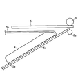
- FIG. 2 is a cross-sectional view showing a peripheral portion of the nip rolls 6 and 6a in the manufacturing system 100.
- FIG. FIG. 2 shows a situation where the substrate 5 is conveyed from the left direction and the polarizing film 5a having an adhesive layer (not shown, the same hereinafter) is conveyed from the lower left direction.
- the polarizing film 5a is provided with a release film 5b.
- the polarizing film 5a and the pressure-sensitive adhesive layer are cut by the half cutter 3, and the release film 5b is not cut (half cut).
- the knife edge 4 is installed on the peeling film 5b side.
- the knife edge 4 is an edge-shaped member for peeling the peeling film 5b, and the polarizing film 5a and the peeling film 5b having a low adhesive force are peeled off along the knife edge 4.
- the release film 5b is wound around the first winding portion 2 in FIG.
- it can replace with a knife edge and can also use the structure which winds up a peeling film using an adhesion roller.
- the winding efficiency of a peeling film can be improved by providing an adhesive roller in two places similarly to a winding part.
- the bonding apparatus 60 conveys the board
- clean air is supplied to the upper surface of the substrate 5 in the bonding apparatus 60. That is, downflow rectification is performed. Thereby, it is possible to perform conveyance and bonding of the substrate 5 in a stable state.
- the bonding device 60 is provided on the upper part of the film transport mechanism 50. Thereby, space saving of the manufacturing system 100 can be achieved.
- a substrate transport mechanism including a conveyor roll is installed in the bonding apparatus 60, whereby the substrate 5 is transported in the transport direction (first substrate transport mechanism 61 and second described later in FIG. 5).
- the substrate transport mechanism 62 corresponds to the substrate transport mechanism).
- the substrate 5 is transported from the left side, and then transported from the right side in the drawing, that is, from the top of the first film transport mechanism 51 to the top of the second film transport mechanism 52.
- the nip rolls 6 * 6a (1st bonding part) and the nip rolls 16 * 16a (2nd bonding part) which are bonding parts are each provided.
- the nip rolls 6, 6 a and 16, 16 a are members that serve to bond the polarizing film from which the release film has been removed to the lower surface of the substrate 5.
- the substrate 5 is reversed by the reversing mechanism 65 after being bonded by the nip rolls 6 and 6a.
- the reversing mechanism 65 will be described later.
- the polarizing film conveyed to the nip rolls 6 and 6a is bonded to the lower surface of the substrate 5 through an adhesive layer.
- known configurations such as a pressure roll and a pressure roll can be employed.
- what is necessary is just to adjust the pressure and temperature at the time of bonding in the nip rolls 6 and 6a suitably.
- the configuration of the nip rolls 16 and 16a is the same.
- a defect display (mark) detection unit is provided between the first unwinding unit 1 and the half cutter, and a polarizing film having a defect is detected. It has a configuration.
- the said defect display is provided at the time of the 1st unwinding part 11 or the 2nd unwinding part 11a rather than a defect display detection part by performing the detection at the time of original film production of a polarizing film, and providing a defect display. It attaches
- the defect display imparting unit includes a camera, an image processing device, and a defect display forming unit. First, a polarizing film is imaged by the camera, and the presence or absence of a defect can be inspected by processing the imaging information. Specific examples of the drawback include foreign matters such as dust and fish eyes. When a defect is detected, a defect display is formed on the polarizing film by the defect display forming unit. A mark such as ink is used as the defect display.
- a bonding avoiding unit discriminates the mark with a camera and transmits a stop signal to the bonding apparatus 60 to stop the conveyance of the substrate 5. Thereafter, the polarizing film in which the defect is detected is not bonded by the nip rolls 6 and 6a and is wound by the defect film winding roller (collecting unit) 7 and 7a. Thereby, pasting with substrate 5 and a polarizing film which has a fault can be avoided. If such a series of structures is provided, it is possible to avoid the bonding between the polarizing film having a defect and the substrate 5, so that the yield can be increased, which is preferable.
- a publicly known inspection sensor can be used suitably as a fault detection part and a pasting avoidance part.
- the substrate 5 is conveyed to the nip rolls 16 and 16a. Then, a polarizing film is bonded to the lower surface of the substrate 5. As a result, the polarizing film is bonded to both surfaces of the substrate 5, and the two polarizing films are bonded to both surfaces of the substrate 5 with different absorption axes. Thereafter, if necessary, the both sides of the substrate 5 are inspected for misalignment.
- the inspection can be usually performed by an inspection unit equipped with a camera.
- the bonding is performed from the lower surface of the substrate 5, and the rectifying environment to the substrate 5 is not hindered. For this reason, foreign matter mixing into the bonding surface of the substrate 5 can be prevented, and more accurate bonding can be performed.
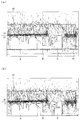
- FIG. 3 (a) and FIG. 3 (b) show the velocity vector of the airflow in the under-paste type manufacturing system similar to the present invention.
- Regions A in FIGS. 3 (a) and 3 (b) are regions where the unwinding part is installed
- region B is a region through which the polarizing film mainly passes
- region C is a region where the winding unit and the like are installed. It is. Further, clean air is supplied from the HEPA filter 40.
- FIG. 3A since the grating 41 through which clean air can pass is installed, the airflow can move in the vertical direction via the grating 41.
- FIG. 3B since the grating 41 is not installed, the airflow moves along the floor after contacting the floor.
- FIGS. 3 (a) and 3 (b) Since the manufacturing system shown in FIGS. 3 (a) and 3 (b) is a bottom-attached type, the air current from the HEPA filter 40 is not hindered by the polarizing film, as shown in FIGS. 9 (a) and 9 (b). For this reason, the direction of the airflow vector is almost directed toward the substrate, and it can be said that a preferable rectification environment is realized in the clean room.
- the grating 41 is installed and not installed in FIG. 3 (b), but both drawings show the same preferable state.
- the substrate transport mechanism is formed horizontally, but it is not installed as a series of structures. For this reason, the airflow can pass between the substrate transport mechanisms. After the substrate is held by a reversing mechanism to be described later, the substrate is transferred between the substrate transport mechanisms.
- substrate 5 is first conveyed by a long side opening (a long side is orthogonal to a conveyance direction), and is conveyed by a short side opening (a short side is orthogonal to a conveyance direction) after that. It has become.
- the reversing mechanism 65 changes the arrangement of the substrate 5 whose short side or long side is along the transport direction to a state where the long side or short side is along the transport direction and reversed.
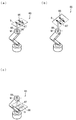
- 4A to 4C are perspective views showing a process of reversing the substrate 5 by the reversing mechanism 65.
- FIG. 4A shows a state where the substrate 5 transported by the first substrate transport mechanism is adsorbed.
- FIG. 4B shows a process of moving the substrate 5, and
- FIG. 4C shows a state in which the substrate 5 is inverted by the second substrate inversion mechanism.
- the first substrate transport mechanism and the second substrate transport mechanism are omitted in FIG. 4, but will be described later with reference to FIG.
- the reversing mechanism 65 includes a suction unit 66, a substrate reversing unit 67, and a lifting unit 68.
- the adsorption unit 66 is a member that adsorbs to the surface of the substrate 5.
- the surface of the substrate 5 is held by the suction unit 66 by the suction unit 66.
- a known adsorption unit can be used, and for example, an air suction type adsorption unit can be used.
- the substrate reversing part 67 is connected to the suction part 66 and is formed so as to connect the suction part 66 and the lifting part 68.
- the substrate reversing unit 67 reverses the substrate 5 by rotating around the reversing axis M.
- the lifting / lowering portion 68 side of the substrate reversing portion 67 has a shape extending toward the substrate 5 in a direction perpendicular to the reversing axis M.
- the suction unit 66 side of the substrate reversing unit 67 has a shape bent about 40 ° along a straight line passing through the center of the substrate 5 in the first substrate transport mechanism and parallel to the long side (transport direction) of the substrate 5. ing.
- the shape of the substrate reversing part 67 shown in FIG. 4A is merely an example, and is not limited to the shape. As another shape, for example, instead of being bent like the substrate reversing portion 67, a shape that is curved from the lifting / lowering portion 68 side to the suction portion 66 side may be employed. Further, a structure having a plurality of movable parts such as a robot arm may be adopted.
- the substrate reversing unit 67 is configured such that a movable unit that can rotate is provided in the lifting unit 68.
- the movable part is arranged along the reversal axis M, and the substrate reversing part 67 is rotatable along the reversal axis M.
- the inversion axis M includes (1) a straight line that passes through the center of the substrate 5 in the first substrate transport mechanism and has an inclination of 45 ° with respect to a straight line perpendicular to the transport direction of the substrate 5, and is perpendicular to the substrate 5. (Refer to FIG. 5A), and (2) located at a position horizontal to the substrate 5 (see FIG. 4A).
- the inversion axis M is located in the plane and may be moved in the direction perpendicular to the substrate 5.
- the substrate reversing unit 67 is configured to rotate along the reversing axis M via the movable unit, but is not limited to this structure as long as it can be rotated along the reversing axis M.
- the substrate reversing unit 67 has a rotating shaft structure, and the rotation shaft structure rotates along the reversing axis M and the entire substrate reversing unit 67 rotates.
- the substrate reversing part 67 is rotated by a driving device such as a motor (not shown).
- the substrate reversing unit 67 can reverse the substrate 5 by one rotation about the reversing axis M. Inversion means that the substrate 5 is rotated to the opposite surface. In other words, the substrate 5 is disposed so that the front surface of the substrate 5 is the back surface.
- the elevating part 68 has an arm shape with a bent part, and the substrate reversing part 67 can be raised by reducing the angle of the arm. On the other hand, the substrate inversion part 67 can be lowered by increasing the angle of the arm.
- the suction unit 66 is disposed above the substrate 5 so as not to contact the substrate 5 when the substrate 5 is not being transported. When the substrate 5 is transferred, the substrate reversing unit 67 is lowered and the adsorption unit 66 is also lowered by the elevating unit 68, so that the substrate 5 can be adsorbed by the adsorption unit 66.
- the adsorption of the adsorption unit 66 is released, but after the release, the substrate reversing unit 67 is moved by the lifting unit 68 and the adsorption unit 66 is separated from the substrate 5.
- FIG. 4A shows a case where the short side of the substrate 5 is along the transport direction.
- the substrate inversion unit 67 rotates along the inversion axis M.
- the vicinity of the center of the substrate 5 is adsorbed by the adsorbing portion 66, but the adsorbing portion is not particularly limited as long as the substrate 5 is fixed so as not to come off during rotation. Further, the number of adsorption locations is not limited to 4 and may be increased or decreased.
- FIG. 4B shows a state in which the substrate reversing unit 67 is rotated by 90 ° with respect to the substrate 5 (in the first substrate transport mechanism) in FIG. 4B, the substrate reversing unit 67 continues to rotate and the substrate 5 is reversed as shown in FIG. 4C.
- the direction of the short side and the long side of the substrate 5 can be changed and reversed by the rotating operation of the reversing mechanism 65 1. That is, the substrate 5 can be reversed with a short tact time without complicated rotation operation. As a result, the polarizing film can be bonded to the substrate 5 including reversal in a short tact time.
- a substrate reversing unit 67 is installed on the transport direction side with respect to the substrate 5 in FIG.
- the second substrate transport mechanism can be reversed in a state where the substrate 5 is moved further in the transport direction.
- the tact time concerning double-sided bonding including reversal can be further shortened.
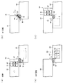
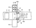
- FIG. 5 is a plan view showing the rotation process of the substrate 5 corresponding to FIG.
- FIG. 5 illustrates the first substrate transport mechanism 61 and the second substrate transport mechanism 62.
- the first substrate transport mechanism 61 and the second substrate transport mechanism 62 are provided with a conveyor roll.
- the first substrate transport mechanism 61 and the second substrate transport mechanism 62 transport the substrate 5 in the same direction.
- the first substrate transport mechanism 61 and the second substrate transport mechanism 62 have a linear shape along the transport direction. That is, it does not have a complicated structure such as an L shape. Therefore, the bonding apparatus 60 according to the present invention is very simple to install and has a structure with excellent area efficiency.
- the substrate reversing portion 67 is rotated by 90 ° so that the substrate 5 is vertical.
- the substrate reversing unit 67 further rotates along the direction of the reversal axis M, and the substrate 5 is reversed.
- the substrate 5 is disposed on a conveyor roll (not shown), and the substrate reversing unit 67 does not contact the conveyor roll. For this reason, the reversing mechanism 65 is located below the substrate 5.
- the suction of the suction part 66 is released, whereby the holding of the substrate 5 is released, and the substrate 5 is transported by the second substrate transport mechanism 62. Then, the reversing mechanism 65 returns to the position shown in FIG. 5A and reverses the other substrates 5 that are sequentially conveyed by the same operation.
- the substrate 5 can be reversed by the operation of 1, and the long side and the short side with respect to the transport direction can be changed.
- a polarizing film is bonded to the lower surface of the substrate 5, and after performing the reversing operation, a polarizing film can be further bonded to the lower surface of the reversed substrate 5. .
- the reversing operation is a simple rotating operation, and the tact time is short because of one operation. Therefore, it is possible to realize bonding with a short tact time without disturbing the rectification environment.
- the reversing operation of the substrate reversing unit 67 is one operation. However, even if the operation of moving the substrate 5 up and down and / or adjusting the position of the substrate reversing unit 67 is included before and after the operation, the present invention Are included in the operation of the reversing mechanism 65.
- the first substrate transport mechanism 61 and the second substrate transport mechanism 62 transport the substrate 5 in the same direction, and have a structure adjacent to each other. This is because, as shown in FIG. 5C, the substrate reversing unit 67 replaces the short side and the long side with respect to the transport direction of the substrate 5, so This is because the transport directions in the transport mechanism 61 are not positioned on a straight line with each other, and a shift occurs.
- the first substrate transport mechanism 61 and the second substrate transport mechanism 62 do not necessarily have to be adjacent to each other, and the first substrate transport mechanism 61 and the second substrate transport mechanism 62 may be spaced from each other.
- the substrate reversing unit 67 is provided on the transport direction side with respect to the substrate 5 before reversal.
- the reversing mechanism 65 may be arranged as shown in FIG. In this case, the substrate 5 cannot be moved further in the transport direction, but it is possible to deal with restrictions such as the arrangement of the reversing mechanism 65.
- FIG. 6 is a plan view showing a modification of the bonding apparatus 60. Changes in the modification include (1) two reversing mechanisms 65, (2) two substrate mounting portions 61 a on both sides of the first substrate transport mechanism 61, and (3 ) The first substrate transport mechanism 61 and the second substrate transport mechanism 62 are arranged on a straight line. The first substrate transport mechanism 61 and the second substrate transport mechanism 62 are the same in that the substrate 5 is transported in the same direction.
- the substrate platform 61a and the reversing mechanism 65 are arranged at both ends of the first substrate transport mechanism 61 on the second substrate transport mechanism 62 side, which are horizontal with respect to the transport direction of the first substrate transport mechanism 61 at the end. Are provided along.
- the reversing mechanism 65 is the same as the structure described in FIGS.
- the end region 61b is provided with transport means for transporting the substrate 5 to the substrate platform 61a.
- a conveyor roll can be mentioned, for example.
- the substrate mounting portion 61a is a place where the substrate 5 is placed by the suction portion 66. According to the modification, the substrates 5 transported to the first substrate transport mechanism 61 are transported alternately to the two substrate platforms 61a. Since two pairs of the substrate platform 61a and the reversing mechanism 65 are provided, the substrate 5 transported to the substrate platform 61a is inverted by the reversing mechanism 65 by one operation.
- the two substrate platforms 61 a are provided along both horizontal directions of the first substrate transport mechanism 61, and the inverted substrate 5 is along the transport direction of the first substrate transport mechanism 61. Will be placed. Therefore, the first substrate transport mechanism 61 and the second substrate transport mechanism 62 can be arranged on a straight line.
- the substrate 5 can be processed twice per unit time. Thereby, since many substrates 5 can be reversed per unit time, the tact time is shortened.
- the bonding apparatus of the structure excellent in area efficiency can be provided. Especially in a clean room, since the area efficiency is required, the bonding apparatus is very preferable.
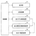
- the manufacturing system 100 includes a control unit 70, a cleaning unit 71, a misalignment inspection device 72, a bonded foreign matter automatic inspection device 73, and a sorting and conveying device 74.
- the bonding deviation inspection device 72, the bonded foreign substance automatic inspection device 73, and the sorting and conveying device 74 perform processing such as inspection on the substrate 5 after bonding, that is, the liquid crystal display device.
- FIG. 7 is a block diagram showing the relation of each member provided in the above-described liquid crystal display device manufacturing system
- FIG. 8 is a flowchart showing the operation of the liquid crystal display device manufacturing system.
- the operation of the liquid crystal display device will be described together with the description of each member.
- the control unit 70 is connected to the cleaning unit 71, the misalignment inspection device 72, the bonded foreign matter automatic inspection device 73, and the sorting and conveying device 74, and controls them by transmitting control signals thereto.
- the control unit 70 is mainly configured by a CPU (Central Processing Unit) and includes a memory or the like as necessary.
- CPU Central Processing Unit
- the cleaning unit 71 In the case where the cleaning unit 71 is provided in the manufacturing system 100, the substrate 5 in the first substrate transport mechanism 61 is transported to the cleaning unit 71 at the front edge of the long side in order to reduce the tact time in the cleaning unit 71. Is preferred. Usually, since the cleaning in the cleaning unit 71 takes a long time, this configuration is very effective from the viewpoint of shortening the tact time.
- a bonding step (including a reversing operation of the substrate 5) for bonding the polarizing film to both surfaces of the substrate 5 is performed (S2 in FIG. 8). This step will be described with reference to FIGS. That's right.
- the sticking deviation inspection device 72 is for inspecting the presence or absence of sticking deviation of the polarizing film on the bonded substrate 5.
- the sticking deviation inspection device 72 is constituted by a camera and an image processing device, and the camera is installed at the bonding position of the substrate 5 on which the polarizing film is bonded by the nip rolls 16 and 16a.
- the substrate 5 is photographed by the camera, and the photographed image information is processed, whereby it is possible to inspect whether or not there is a sticking deviation on the substrate 5 (sticking deviation inspection step, S3 in FIG. 8).
- the misalignment inspection apparatus 72 a conventionally known misalignment inspection apparatus can be used as the misalignment inspection apparatus 72.
- the bonded foreign matter automatic inspection device 73 inspects the presence or absence of foreign matter on the bonded substrate 5.
- the bonded foreign matter automatic inspection device 73 is configured by a camera and an image processing device, like the misalignment inspection device 72, and transports the second substrate of the substrate 5 after the polarizing film is bonded by the nip rolls 16 and 16a.
- the camera is installed in the mechanism (bonding device 60).
- substrate 5 is image
- the foreign matter include foreign matters such as dust, fish eyes, and the like.
- a conventionally well-known bonding foreign material inspection apparatus can be used as the bonding foreign material automatic inspection apparatus 73.
- S3 and S4 may be performed in the reverse order or simultaneously. One step can be omitted.
- the sorting and conveying device 74 determines the presence or absence of sticking misalignment and foreign matter based on the inspection results from the sticking misalignment inspection device 72 and the bonded foreign matter automatic inspection device 73.
- the sorting and conveying device 74 only needs to receive an output signal based on the inspection result from the sticking misalignment inspection device 72 and the bonding foreign matter automatic inspection device 73 and can sort the bonded substrates 5 into non-defective products or defective products. . Therefore, a conventionally known sorting and conveying system can be used.
- both the misalignment and foreign matter are detected.
- the bonded substrate 5 is not used. Sorted as good (S7).
- the bonded substrates 5 are classified as non-defective products (S6).
- the non-defective product and the defective product can be quickly sorted, and the tact time can be shortened.
- the sorting and conveying device 74 may be configured to determine the presence / absence of only one of the sticking misalignment and the foreign matter.
- the polarizing film bonding apparatus according to the present invention can be used in the field of bonding a polarizing film to a substrate.
Landscapes
- Physics & Mathematics (AREA)
- Nonlinear Science (AREA)
- General Physics & Mathematics (AREA)
- Optics & Photonics (AREA)
- Chemical & Material Sciences (AREA)
- Crystallography & Structural Chemistry (AREA)
- Liquid Crystal (AREA)
- Engineering & Computer Science (AREA)
- Manufacturing & Machinery (AREA)
- Mathematical Physics (AREA)
- Polarising Elements (AREA)
Abstract
Description
Efficiency Particulate Air )フィルター40からはクリーンエアーが供給される。なお、図9(a)では、クリーンエアーが通過可能なグレーチング41が設置されているためグレーチング41を介して気流が垂直方向に移動することが可能である。一方、図9(b)では、グレーチング41が設置されていないため、気流は図9(b)最下部の床に接触した後、床に沿って移動することとなる。
長方形の基板を長辺または短辺が搬送方向に沿った状態にて搬送する第1基板搬送機構と、
上記基板を短辺または長辺が搬送方向に沿った状態にて搬送する第2基板搬送機構とを備える基板搬送機構において、
基板反転部の反転動作により、上記第1基板搬送機構にて搬送された上記基板を反転させるとともに、配置を変更して上記第2基板搬送機構に配置するように構成されている反転機構を備えている
ものである。
上記第1発明において、
上記反転機構が、駆動装置の回転駆動により、上記基板の搬送方向に対して一定の傾きで配設された反転軸回りに回転して反転動作する基板反転部を備えている
ものである。
上記第2発明において、
上記反転軸の上記傾きが、45°である
ものである。
上記第3発明において、
上記基板反転部の一端が、上記反転軸に対して45°の傾きで配設されているものである。
上記第1発明ないし第4発明のいずれかにおいて、
上記反転機構の上記反転軸と上記第1基板搬送機構にて搬送された上記基板および上記第2基板搬送機構に上記基板反転部によって反転して配置された上記基板が、同一平面に配置される
ものである。
上記第1発明ないし第5発明のいずれかにおいて、
上記反転機構が、上記反転軸の昇降、傾きおよび位置の調整を可能にする手段を備えている
ものである。
上記第1発明ないし第6発明のいずれかにおいて、
上記第1基板搬送機構の両側に2個の反転機構が配設され、上記第1基板搬送機構の両側に、上記第1基板搬送機構によって搬送された上記基板が交互に搬送される2個の基板載置部が配設され、上記2個の基板載置部に搬送された上記基板が、上記2個の反転機構によって交互に反転されるとともに、配置が変更され上記第2基板搬送機構に配置するように構成されている
ものである。
長方形の基板を長辺または短辺が搬送方向に沿った状態にて搬送する第1基板搬送機構と、
上記第1基板搬送機構における上記基板の下面に偏光フィルムを貼合する第1貼合部と、
上記基板を短辺または長辺が搬送方向に沿った状態にて搬送する第2基板搬送機構と、
上記第2基板搬送機構における上記基板の下面に偏光フィルムを貼合する第2貼合部とを含む偏光フィルムの貼合装置において、
基板反転部の反転動作により、上記第1基板搬送機構にて搬送された上記基板を反転させるとともに、配置を変更して上記第2基板搬送機構に配置するように構成されている反転機構を備えている
ものである。
長方形の基板を長辺または短辺が搬送方向に沿った状態にて搬送する第1基板搬送機構と、
上記第1基板搬送機構における上記基板の下面に偏光フィルムを貼合する第1貼合部と、
上記基板を短辺または長辺が搬送方向に沿った状態にて搬送する第2基板搬送機構と、
上記第2基板搬送機構における上記基板の下面に偏光フィルムを貼合する第2貼合部と、
上記第1基板搬送機構にて搬送された上記基板を保持する保持部を備え、上記保持部を保持状態または保持が解かれる状態に制御する保持機構とを含む偏光フィルムの貼合装置において、
駆動装置の回転駆動に基づく、上記保持機構の上記保持部に一端が連結された基板反転部の反転動作により、上記第1基板搬送機構にて搬送され上記保持部に保持された上記基板を反転させるとともに、配置を変更して上記第2基板搬送機構に配置するように構成されている反転機構を備えている
ものである。
第8発明または第9発明において、
上記反転軸の上記傾きが、45°である
ものである。
第10発明において、
上記基板反転部の一端が、上記反転軸に対して45°の傾きで配設されているものである。
第11発明において、
上記反転軸は、第1基板搬送機構における基板の中心を通り、上記基板の搬送方向と垂直な直線を基準として45°の傾きを有する直線を含み、上記基板と垂直な面内に位置する
ものである。
第8発明ないし第12発明のいずれかにおいて、
上記反転機構の上記反転軸と上記第1基板搬送機構にて搬送された上記基板および上記第2基板搬送機構に上記基板反転部によって反転して配置された上記基板が、同一平面に配置される
ものである。
第8発明ないし第13発明のいずれかにおいて、
上記反転機構が、上記反転軸の昇降、傾きおよび位置の調整を可能にする手段を備えている
ものである。
第8発明ないし第14発明のいずれかにおいて、
上記第1基板搬送機構の両側に2個の反転機構が配設され、上記第1基板搬送機構の両側に、上記第1基板搬送機構によって搬送された上記基板が交互に搬送される2個の基板載置部が配設され、上記2個の基板載置部に搬送された上記基板が、上記2個の反転機構によって交互に反転されるとともに、配置が変更され上記第2基板搬送機構に配置されるように構成されている
ものである。
本発明の偏光フィルムの貼合装置は、上記課題を解決するために、長方形の基板を長辺または短辺が搬送方向に沿った状態にて搬送する第1基板搬送機構と、上記第1基板搬送機構における上記基板の下面に偏光フィルムを貼合する第1貼合部と、上記第1基板搬送機構にて搬送された上記基板を反転させて第2基板搬送機構に配置する反転機構と、上記基板を短辺または長辺が搬送方向に沿った状態にて搬送する第2基板搬送機構と、上記第2基板搬送機構における上記基板の下面に偏光フィルムを貼合する第2貼合部とを含む偏光フィルムの貼合装置であって、上記第1基板搬送機構および第2基板搬送機構は、基板を同一方向に搬送するものであり、第1基板搬送機構における長辺または短辺が搬送方向に沿った基板を吸着して反転させ、第2基板搬送機構において短辺または長辺が搬送方向に沿った状態にする反転機構を備え、上記反転機構は、基板を吸着する吸着部と、吸着部に連結した基板反転部を備え、上記基板反転部は反転軸に沿って回転することにより基板を反転させるものであり、上記反転軸は、下記(1)の面内に位置すると共に、下記(2)の垂直な位置にあることを特徴としている。
(1)第1基板搬送機構における基板の中心を通り、上記基板の搬送方向と垂直な直線を基準として45°の傾きを有する直線を含み、上記基板と垂直な面内
(2)第1基板搬送機構における基板に対して垂直な位置
上記の発明によれば、第1貼合部によって基板の下面に偏光フィルムを貼合し、反転機構における基板反転部の反転軸に沿った回転によって、基板を反転させると共に、搬送方向に対する長辺および短辺を変更することができる。その後、第2貼合部によって基板の下面に偏光フィルムを貼合することができる。すなわち、基板の両面に対して、下面から偏光フィルムを貼合することができるため、整流環境を妨げることがない。また、反転機構の動作は単純な1動作であるため、タクトタイムが短い。したがって、タクトタイムの短い貼合をも実現できる。さらに、上記第1基板搬送機構と第2基板搬送機構とが基板を同一方向に搬送するものである。すなわち、L字型形状などの複雑な構造を有していない。したがって、本発明に係る貼合装置は、設置が非常に簡便であり、面積効率に優れる。
本発明の偏光フィルムの貼合装置は、以上のように、上記第1基板搬送機構および第2基板搬送機構は、基板を同一方向に搬送するものであり、第1基板搬送機構における長辺または短辺が搬送方向に沿った基板を吸着して反転させ、第2基板搬送機構において短辺または長辺が搬送方向に沿った状態にする反転機構を備え、上記反転機構は、基板を吸着する吸着部と、吸着部に連結した基板反転部を備え、上記基板反転部は反転軸に沿って回転することにより基板を反転させるものであり、上記反転軸は、下記(1)の面内に位置すると共に、下記(2)の垂直な位置にあるものである。
(1)第1基板搬送機構における基板の中心を通り、上記基板の搬送方向と垂直な直線を基準として45°の傾きを有する直線を含み、上記基板と垂直な面内
(2)第1基板搬送機構における基板に対して垂直な位置
それゆえ、上記反転機構によって基板を反転させると共に、搬送方向に対する長辺および短辺を変更することができる。これにより、基板の両面に対して、下面から偏光フィルムを貼合することができるため、整流環境を妨げることがない。また、反転機構の動作は単純な1動作であるため、タクトタイムが短い。したがって、タクトタイムの短い貼合をも実現できる。さらに、上記第1基板搬送機構と第2基板搬送機構とは基板を同一方向に搬送するものである。すなわち、L字型形状などの複雑な構造を有していない。したがって、本発明に係る貼合装置は、設置が非常に簡便であり、面積効率に優れるという効果をも奏する。
まず、フィルム搬送機構50について説明する。フィルム搬送機構50は、偏光フィルム(偏光板)を巻出してニップロール6・6aおよび16・16aまで搬送し、不要となった剥離フィルムを巻き取る役割を果たす。一方、貼合装置60はフィルム搬送機構50によって巻出された偏光フィルムを基板(液晶パネル)5に対して貼合する役割を果たすものである。
貼合装置60はフィルム搬送機構50の上部に備えられている。これにより、製造システム100の省スペース化を図ることができる。図示しないが、貼合装置60にはコンベアーロールを備える基板搬送機構が設置されており、これにより基板5が搬送方向へ搬送される(図5にて後述する第1基板搬送機構61・第2基板搬送機構62が基板搬送機構に該当する)。
反転機構65は、短辺または長辺が搬送方向に沿った基板5を、長辺または短辺が搬送方向に沿った状態であり、反転された状態に配置を変更するものである。図4(a)~(c)は反転機構65によって基板5を反転させる過程を示す斜視図である。
さらに、好ましい形態として、製造システム100は、制御部70、洗浄部71、貼りずれ検査装置72および貼合異物自動検査装置73および仕分け搬送装置74を備えている。貼りずれ検査装置72、貼合異物自動検査装置73および仕分け搬送装置74は、貼合後の基板5、すなわち、液晶表示装置に対して検査等の処理を行うものである。
1a 第2巻出部
2 第1巻取部
2a 第2巻取部
3 ハーフカッター
4 ナイフエッジ
5 基板
5a 偏光フィルム
5b 剥離フィルム
6・6a ニップロール(第1貼合部)
7・7a 欠点フィルム巻取ローラー
11 第1巻出部
11a 第2巻出部
12 第1巻取部
12a 第2巻取部
13 ハーフカッター
14 ナイフエッジ
16・16a ニップロール(第2貼合部)
17・17a 欠点フィルム巻取ローラー
40 HEPAフィルター
41 グレーチング
50 フィルム搬送機構
51 第1フィルム搬送機構
52 第2フィルム搬送機構
60 貼合装置(偏光フィルムの貼合装置)
61 第1基板搬送機構
61a 基板載置部
62 第2基板搬送機構
65 反転機構
66 吸着部
67 基板反転部
68 昇降部
70 制御部
71 洗浄部
72 検査装置
73 貼合異物自動検査装置
74 搬送装置
100 製造システム(液晶表示装置の製造システム)
M 反転軸
Claims (15)
- 長方形の基板を長辺または短辺が搬送方向に沿った状態にて搬送する第1基板搬送機構と、
上記基板を短辺または長辺が搬送方向に沿った状態にて搬送する第2基板搬送機構とを備える基板搬送機構において、
基板反転部の反転動作により、上記第1基板搬送機構にて搬送された上記基板を反転させるとともに、配置を変更して上記第2基板搬送機構に配置するように構成されている反転機構を備えている
基板搬送機構における反転機構。 - 請求項1において、
上記反転機構が、駆動装置の回転駆動により、上記基板の搬送方向に対して一定の傾きで配設された反転軸回りに回転して反転動作する基板反転部を備えている
基板搬送機構における反転機構。 - 請求項2において、
上記反転軸の上記傾きが、45°である
基板搬送機構における反転機構。 - 請求項3において、
上記基板反転部の一端が、上記反転軸に対して45°の傾きで配設されている
基板搬送機構における反転機構。 - 請求項1ないし請求項4のいずれかにおいて、
上記反転機構の上記反転軸と上記第1基板搬送機構にて搬送された上記基板および上記第2基板搬送機構に上記基板反転部によって反転して配置された上記基板が、同一平面に配置される
基板搬送機構における反転機構。 - 請求項1ないし請求項5のいずれかにおいて、
上記反転機構が、上記反転軸の昇降、傾きおよび位置の調整を可能にする手段を備えている
基板搬送機構における反転機構。 - 請求項1ないし請求項6のいずれかにおいて、
上記第1基板搬送機構の両側に2個の反転機構が配設され、上記第1基板搬送機構の両側に、上記第1基板搬送機構によって搬送された上記基板が交互に搬送される2個の基板載置部が配設され、上記2個の基板載置部に搬送された上記基板が、上記2個の反転機構によって交互に反転されるとともに、配置が変更され上記第2基板搬送機構に配置するように構成されている
基板搬送機構における反転機構。 - 長方形の基板を長辺または短辺が搬送方向に沿った状態にて搬送する第1基板搬送機構と、
上記第1基板搬送機構における上記基板の下面に偏光フィルムを貼合する第1貼合部と、
上記基板を短辺または長辺が搬送方向に沿った状態にて搬送する第2基板搬送機構と、
上記第2基板搬送機構における上記基板の下面に偏光フィルムを貼合する第2貼合部とを含む偏光フィルムの貼合装置において、
基板反転部の反転動作により、上記第1基板搬送機構にて搬送された上記基板を反転させるとともに、配置を変更して上記第2基板搬送機構に配置するように構成されている反転機構を備えている
偏光フィルムの貼合装置における反転機構。 - 長方形の基板を長辺または短辺が搬送方向に沿った状態にて搬送する第1基板搬送機構と、
上記第1基板搬送機構における上記基板の下面に偏光フィルムを貼合する第1貼合部と、
上記基板を短辺または長辺が搬送方向に沿った状態にて搬送する第2基板搬送機構と、
上記第2基板搬送機構における上記基板の下面に偏光フィルムを貼合する第2貼合部と、
上記第1基板搬送機構にて搬送された上記基板を保持する保持部を備え、上記保持部を保持状態または保持が解かれる状態に制御する保持機構とを含む偏光フィルムの貼合装置において、
駆動装置の回転駆動に基づく、上記保持機構の上記保持部に一端が連結された基板反転部の反転動作により、上記第1基板搬送機構にて搬送され上記保持部に保持された上記基板を反転させるとともに、配置を変更して上記第2基板搬送機構に配置するように構成されている反転機構を備えている
偏光フィルムの貼合装置における反転機構。 - 請求項8または請求項9において、
上記反転軸の上記傾きが、45°である
偏光フィルムの貼合装置における反転機構。 - 請求項10において、
上記基板反転部の一端が、上記反転軸に対して45°の傾きで配設されている
偏光フィルムの貼合装置における反転機構。 - 請求項11において、
上記反転軸は、第1基板搬送機構における基板の中心を通り、上記基板の搬送方向と垂直な直線を基準として45°の傾きを有する直線を含み、上記基板と垂直な面内に位置する
偏光フィルムの貼合装置における反転機構。 - 請求項8ないし請求項12のいずれかにおいて、
上記反転機構の上記反転軸と上記第1基板搬送機構にて搬送された上記基板および上記第2基板搬送機構に上記基板反転部によって反転して配置された上記基板が、同一平面に配置される
偏光フィルムの貼合装置における反転機構。 - 請求項8ないし請求項13のいずれかにおいて、
上記反転機構が、上記反転軸の昇降、傾きおよび位置の調整を可能にする手段を備えている
偏光フィルムの貼合装置における反転機構。 - 請求項8ないし請求項14のいずれかにおいて、
上記第1基板搬送機構の両側に2個の反転機構が配設され、上記第1基板搬送機構の両側に、上記第1基板搬送機構によって搬送された上記基板が交互に搬送される2個の基板載置部が配設され、上記2個の基板載置部に搬送された上記基板が、上記2個の反転機構によって交互に反転されるとともに、配置が変更され上記第2基板搬送機構に配置されるように構成されている
偏光フィルムの貼合装置における反転機構。
Priority Applications (2)
| Application Number | Priority Date | Filing Date | Title |
|---|---|---|---|
| CN201180017069.XA CN102822727B (zh) | 2010-03-30 | 2011-03-29 | 基板输送机构以及偏振膜的贴合装置中的翻转机构 |
| KR1020127014501A KR101419619B1 (ko) | 2010-03-30 | 2011-03-29 | 기판 반송 기구 및 편광 필름의 접합 장치에서의 반전 기구 |
Applications Claiming Priority (2)
| Application Number | Priority Date | Filing Date | Title |
|---|---|---|---|
| JP2010-079455 | 2010-03-30 | ||
| JP2010079455 | 2010-03-30 |
Publications (1)
| Publication Number | Publication Date |
|---|---|
| WO2011122005A1 true WO2011122005A1 (ja) | 2011-10-06 |
Family
ID=44711762
Family Applications (2)
| Application Number | Title | Priority Date | Filing Date |
|---|---|---|---|
| PCT/JP2011/001869 Ceased WO2011122005A1 (ja) | 2010-03-30 | 2011-03-29 | 基板搬送機構および偏光フィルムの貼合装置における反転機構 |
| PCT/JP2011/001865 Ceased WO2011122001A1 (ja) | 2010-03-30 | 2011-03-29 | 偏光フィルムの貼合装置およびこれを備える液晶表示装置の製造システム |
Family Applications After (1)
| Application Number | Title | Priority Date | Filing Date |
|---|---|---|---|
| PCT/JP2011/001865 Ceased WO2011122001A1 (ja) | 2010-03-30 | 2011-03-29 | 偏光フィルムの貼合装置およびこれを備える液晶表示装置の製造システム |
Country Status (4)
| Country | Link |
|---|---|
| KR (2) | KR101140872B1 (ja) |
| CN (2) | CN102472902B (ja) |
| TW (2) | TWI401503B (ja) |
| WO (2) | WO2011122005A1 (ja) |
Families Citing this family (12)
| Publication number | Priority date | Publication date | Assignee | Title |
|---|---|---|---|---|
| JP5328970B2 (ja) * | 2011-11-21 | 2013-10-30 | 住友化学株式会社 | 光学表示デバイスの生産システム及び生産方法 |
| JP6064684B2 (ja) * | 2013-03-05 | 2017-01-25 | 三星ダイヤモンド工業株式会社 | 基板処理システムおよび基板反転装置 |
| JP6127707B2 (ja) * | 2013-05-16 | 2017-05-17 | 住友化学株式会社 | 光学表示デバイスの生産システム及び生産方法 |
| JP6178660B2 (ja) * | 2013-08-08 | 2017-08-09 | 住友化学株式会社 | 光学表示デバイスの生産システム |
| CN104678612B (zh) * | 2013-11-29 | 2018-12-14 | 芝浦机械电子装置株式会社 | 基板贴合装置、显示面板制造装置及显示面板制造方法 |
| TWI548110B (zh) * | 2015-01-12 | 2016-09-01 | 精曜有限公司 | 基板自動傳輸系統 |
| CN104709504B (zh) * | 2015-03-27 | 2017-02-01 | 广东韦达尔科技有限公司 | 一种全自动高效贴膜机 |
| KR101745268B1 (ko) | 2016-06-20 | 2017-06-08 | 주식회사 엘지화학 | 패널 반전 장치, 광학 표시 소자의 제조 시스템 및 방법 |
| TWI602652B (zh) * | 2016-11-09 | 2017-10-21 | 住華科技股份有限公司 | 翻轉裝置及應用其之光學膜的製造方法 |
| EP3730430B1 (de) * | 2019-04-23 | 2021-09-01 | Uhlmann Pac-Systeme GmbH & Co. KG | Übergabeeinheit und verfahren zum transferieren von blisterpackungen |
| CN110579892A (zh) * | 2019-08-15 | 2019-12-17 | 深圳市华星光电半导体显示技术有限公司 | 偏光片贴付装置 |
| CN114940015A (zh) * | 2022-05-07 | 2022-08-26 | 宁波维真显示科技股份有限公司 | 一种柔性3dled及其制备装置及制备方法 |
Citations (5)
| Publication number | Priority date | Publication date | Assignee | Title |
|---|---|---|---|---|
| JP2003019687A (ja) * | 2001-07-03 | 2003-01-21 | Aitec:Kk | ロボットハンドの駆動装置 |
| JP2004325539A (ja) * | 2003-04-22 | 2004-11-18 | Sharp Corp | 基板への偏光板貼付方法及び貼付装置 |
| JP2005037417A (ja) * | 2002-06-28 | 2005-02-10 | Fuji Photo Film Co Ltd | 偏光板貼合方法及び装置 |
| JP2009175653A (ja) * | 2007-12-27 | 2009-08-06 | Nitto Denko Corp | 光学表示装置の製造システム及び製造方法 |
| WO2010131597A1 (ja) * | 2009-05-15 | 2010-11-18 | 日東電工株式会社 | 光学表示装置の製造システム及び製造方法 |
Family Cites Families (6)
| Publication number | Priority date | Publication date | Assignee | Title |
|---|---|---|---|---|
| KR20040002796A (ko) * | 2002-06-28 | 2004-01-07 | 후지 샤신 필름 가부시기가이샤 | 편광판 점착방법 및 그 장치 |
| KR100506979B1 (ko) | 2003-06-19 | 2005-08-09 | 삼성전자주식회사 | 최대변화 지연특성을 갖는 지연회로를 구비한 반도체 장치 |
| TW200608084A (en) * | 2004-08-18 | 2006-03-01 | Takatori Corp | A method and a device for sticking a optical film to a optical device |
| TWM270907U (en) * | 2004-11-19 | 2005-07-21 | Easy Field Corp | Laminating machine for polarizer |
| JP4406043B2 (ja) * | 2008-04-16 | 2010-01-27 | 日東電工株式会社 | ロール原反セット、及びロール原反の製造方法 |
| CN201242637Y (zh) * | 2008-07-30 | 2009-05-20 | 阳程科技股份有限公司 | 同侧供料的贴附装置 |
-
2011
- 2011-03-29 WO PCT/JP2011/001869 patent/WO2011122005A1/ja not_active Ceased
- 2011-03-29 KR KR1020127002006A patent/KR101140872B1/ko active Active
- 2011-03-29 CN CN201180003075.XA patent/CN102472902B/zh active Active
- 2011-03-29 KR KR1020127014501A patent/KR101419619B1/ko active Active
- 2011-03-29 WO PCT/JP2011/001865 patent/WO2011122001A1/ja not_active Ceased
- 2011-03-29 CN CN201180017069.XA patent/CN102822727B/zh active Active
- 2011-03-29 TW TW100110809A patent/TWI401503B/zh active
- 2011-03-29 TW TW100110815A patent/TWI517285B/zh active
Patent Citations (5)
| Publication number | Priority date | Publication date | Assignee | Title |
|---|---|---|---|---|
| JP2003019687A (ja) * | 2001-07-03 | 2003-01-21 | Aitec:Kk | ロボットハンドの駆動装置 |
| JP2005037417A (ja) * | 2002-06-28 | 2005-02-10 | Fuji Photo Film Co Ltd | 偏光板貼合方法及び装置 |
| JP2004325539A (ja) * | 2003-04-22 | 2004-11-18 | Sharp Corp | 基板への偏光板貼付方法及び貼付装置 |
| JP2009175653A (ja) * | 2007-12-27 | 2009-08-06 | Nitto Denko Corp | 光学表示装置の製造システム及び製造方法 |
| WO2010131597A1 (ja) * | 2009-05-15 | 2010-11-18 | 日東電工株式会社 | 光学表示装置の製造システム及び製造方法 |
Also Published As
| Publication number | Publication date |
|---|---|
| WO2011122001A1 (ja) | 2011-10-06 |
| KR101419619B1 (ko) | 2014-07-15 |
| KR20120021330A (ko) | 2012-03-08 |
| CN102822727B (zh) | 2015-06-10 |
| KR20130018221A (ko) | 2013-02-20 |
| TW201145436A (en) | 2011-12-16 |
| CN102822727A (zh) | 2012-12-12 |
| CN102472902A (zh) | 2012-05-23 |
| KR101140872B1 (ko) | 2012-05-03 |
| TW201137464A (en) | 2011-11-01 |
| TWI517285B (zh) | 2016-01-11 |
| CN102472902B (zh) | 2014-02-05 |
| TWI401503B (zh) | 2013-07-11 |
Similar Documents
| Publication | Publication Date | Title |
|---|---|---|
| WO2011122005A1 (ja) | 基板搬送機構および偏光フィルムの貼合装置における反転機構 | |
| JP5079114B2 (ja) | 基板搬送機構および偏光フィルムの貼合装置における基板支持装置 | |
| JP4751997B1 (ja) | 偏光フィルムの貼合装置およびこれを備える液晶表示装置の製造システム | |
| JP5613582B2 (ja) | 偏光フィルムの貼合装置およびこれを備える液晶表示装置の製造システム | |
| JP5170913B2 (ja) | 偏光フィルムの貼合装置およびこれを備える液晶表示装置の製造システム | |
| JP5616054B2 (ja) | 偏光フィルムの貼合装置およびこれを備える液晶表示装置の製造システム | |
| JP5523916B2 (ja) | 偏光フィルムの貼合装置およびこれを備える液晶表示装置の製造システム | |
| JP5144777B2 (ja) | 基板搬送機構および偏光フィルムの貼合装置における基板支持部を備えた反転機構 | |
| JP4863332B2 (ja) | 偏光フィルムの貼合装置および液晶表示装置の製造システム | |
| JP5281725B2 (ja) | 基板搬送機構および偏光フィルムの貼合装置における反転機構 | |
| JP5087174B2 (ja) | 液晶表示装置の製造システムおよび製造方法 |
Legal Events
| Date | Code | Title | Description |
|---|---|---|---|
| WWE | Wipo information: entry into national phase |
Ref document number: 201180017069.X Country of ref document: CN |
|
| 121 | Ep: the epo has been informed by wipo that ep was designated in this application |
Ref document number: 11762251 Country of ref document: EP Kind code of ref document: A1 |
|
| ENP | Entry into the national phase |
Ref document number: 20127014501 Country of ref document: KR Kind code of ref document: A |
|
| NENP | Non-entry into the national phase |
Ref country code: DE |
|
| 122 | Ep: pct application non-entry in european phase |
Ref document number: 11762251 Country of ref document: EP Kind code of ref document: A1 |