WO2011121885A1 - Frame structure for saddled vehicle - Google Patents
Frame structure for saddled vehicle Download PDFInfo
- Publication number
- WO2011121885A1 WO2011121885A1 PCT/JP2011/001147 JP2011001147W WO2011121885A1 WO 2011121885 A1 WO2011121885 A1 WO 2011121885A1 JP 2011001147 W JP2011001147 W JP 2011001147W WO 2011121885 A1 WO2011121885 A1 WO 2011121885A1
- Authority
- WO
- WIPO (PCT)
- Prior art keywords
- seat rail
- frame
- hole
- pivot frame
- pipe
- Prior art date
Links
Images


Classifications
-
- B—PERFORMING OPERATIONS; TRANSPORTING
- B62—LAND VEHICLES FOR TRAVELLING OTHERWISE THAN ON RAILS
- B62K—CYCLES; CYCLE FRAMES; CYCLE STEERING DEVICES; RIDER-OPERATED TERMINAL CONTROLS SPECIALLY ADAPTED FOR CYCLES; CYCLE AXLE SUSPENSIONS; CYCLE SIDE-CARS, FORECARS, OR THE LIKE
- B62K19/00—Cycle frames
- B62K19/18—Joints between frame members
- B62K19/20—Joints between frame members welded, soldered, or brazed
-
- B—PERFORMING OPERATIONS; TRANSPORTING
- B62—LAND VEHICLES FOR TRAVELLING OTHERWISE THAN ON RAILS
- B62K—CYCLES; CYCLE FRAMES; CYCLE STEERING DEVICES; RIDER-OPERATED TERMINAL CONTROLS SPECIALLY ADAPTED FOR CYCLES; CYCLE AXLE SUSPENSIONS; CYCLE SIDE-CARS, FORECARS, OR THE LIKE
- B62K11/00—Motorcycles, engine-assisted cycles or motor scooters with one or two wheels
- B62K11/02—Frames
- B62K11/04—Frames characterised by the engine being between front and rear wheels
-
- B—PERFORMING OPERATIONS; TRANSPORTING
- B62—LAND VEHICLES FOR TRAVELLING OTHERWISE THAN ON RAILS
- B62K—CYCLES; CYCLE FRAMES; CYCLE STEERING DEVICES; RIDER-OPERATED TERMINAL CONTROLS SPECIALLY ADAPTED FOR CYCLES; CYCLE AXLE SUSPENSIONS; CYCLE SIDE-CARS, FORECARS, OR THE LIKE
- B62K19/00—Cycle frames
- B62K19/30—Frame parts shaped to receive other cycle parts or accessories
Definitions
- the present invention relates to a frame structure of a saddle-ride type vehicle.
- a motorcycle has a frame structure in which a seat frame is welded to a rear portion of a pivot frame (see, for example, Patent Document 1).
- This Patent Document 1 discloses a head pipe, a main pipe extending rearward and downward from the head pipe, a pair of left and right center upper pipes welded to a rear portion of the main pipe and extending rearward, and a center pipe extending downward from the center upper pipe.
- a seat rail whose front end upper part is welded to the rear end of the center upper pipe and extends rearward, a rear pipe that extends downward from the front end lower part of the seat rail, and a pair of left and right pivot frames connected to the lower part of the rear pipe.
- a vehicle frame structure is disclosed.
- the pivot frame has a gusset shape, a rear pipe extending downward from the lower front end of the seat rail is provided, and the outer edge of the pivot frame and the peripheral surface of the rear pipe are welded.
- the seat load acts on both the rear pipe and the center upper pipe, and the vehicle body frame has sufficient rigidity with respect to the seat load by providing a large gap between the center upper pipe and the rear pipe. Therefore, the strength of the welded portion between the rear pipe and the pivot frame is ensured.
- the frame structure without the member for connecting the seat rail and the main frame (the rear part of the center upper pipe in Patent Document 1), and the rear part of the pivot frame, the distance between the seat rail and the back stay constituting the rear pipe is set.
- a narrow frame structure it becomes difficult to ensure the rigidity of the vehicle body frame against the seat load.
- the bending stress acting on the welded portion between the pivot frame and the rear pipe is increased, the welded portion on the upper front surface of the rear pipe is subjected to a large tensile stress, and the welded portion on the lower rear surface of the rear pipe is subjected to a large compressive stress.
- the present invention has been made in view of the above-described circumstances, and provides a frame structure of a saddle-ride type vehicle that can easily secure the bending strength of the welded portion by, for example, a structure in which a seat rail is welded to the rear portion of the pivot frame.
- the purpose is that.
- the present invention provides a pivot frame (14) that swingably supports a rear arm (28) that pivotally supports a rear wheel (27) at a rear portion, and a rear portion of the pivot frame (14).
- a hole portion along a front axis of the seat rail (15) is formed on a side surface of the pivot frame (14).
- 71A the pivot frame (14) and the front portion of the seat rail (15) are welded at the periphery of the hole (71A).
- the pivot frame is welded to the seat rail at an upper and lower intermediate position, so that it is possible to efficiently secure a strong joint strength against a bending moment caused by the seat load, and to easily secure the bending strength.
- the pivot frame (14) is configured by joining open end edges (W) of the left and right plate portions (81A, 81B) that are matched in the middle, and the left and right plate portions (81A, 81B).
- a seat rail insertion opening (84) is provided on the rear upper side of the pivot frame (14), and the hole (71A) is provided in both the left and right plate parts (81A, 81B). May be.
- the back stay (16) is joined to the rear part of the pivot frame (14) below the seat rail (15), extends rearward and upward, and is joined to the rear part of the seat rail (15).
- a back stay insertion opening (86) is provided below the seat rail insertion opening (84) of the pivot frame (14), and the back stay insertion opening (86) is provided on a side surface of the back stay insertion opening (86).
- a lower hole (71B) is provided along the front shaft (16L) of the stay (16), and the pivot frame (14) and the back stay (16) are provided at the periphery of the lower hole (71B).
- the front part may be welded.
- the lower hole portion along the axis of the front portion of the back stay is provided on the side surface of the back stay insertion opening portion of the pivot frame, and the pivot frame and the back stay are arranged at the periphery of the lower hole portion. Since the front part is welded, the back stay that suppresses the deflection of the seat rail can be made to have the same welded structure as the seat rail, and the bending strength against the seat load can be easily secured.
- the pivot frame (14) is provided in a pair of left and right, a cross pipe (32) is provided between the left and right pivot frames (14), and the cross pipe (32) is connected to the seat rail (15). ) May be provided adjacent to the front lower side on the front shaft (15L).
- the cross pipe between the left and right pivot frames is provided adjacent to the front lower side on the front shaft of the seat rail, the rigidity of the pivot frame around the joint portion of the seat rail is further increased. Can do.
- the front portion of the seat rail (15) has a pipe shape
- the hole portion (71A) has a circumferential length equal to or greater than the circumferential length of the pipe at the front portion of the seat rail (15). It may be a long hole.
- the hole for welding the pivot frame and the front part of the seat rail is a long hole whose peripheral length is greater than or equal to the peripheral length of the front part of the seat rail, so that a long welding length can be secured. It is possible to easily secure the bonding strength.
- this invention provides a hollow box-shaped member (14) by bending the edge part of a pair of plate-shaped member (81A, 81B), and welding the edge part,
- the box-shaped member (14) is provided.
- a frame structure of a saddle-ride type vehicle formed by welding a plurality of pipes (15, 16)
- openings (84, 86) through which the pipes (15, 16) are inserted into the box-shaped member (14).
- the box-like member (14) and the pipes (15, 16) are welded at the periphery of (71).
- the load which the welding part of a box-shaped member and a pipe receives by bending moment can be made as small as possible, and bending strength can be ensured easily.
- the said structure WHEREIN:
- the said hole (71) is good also as an elongate hole which follows the axis
- a hole along the axis of the front part of the seat rail is provided on the side surface of the pivot frame, and the pivot frame and the front part of the seat rail are welded at the periphery of the hole part.
- the pivot frame is configured by joining the open end edges of the left and right plate portions that are adjusted in the middle, and the left and right plate portions are provided with seat rail insertion openings at the upper rear of the pivot frame, and the hole portions.
- it is provided on both the left and right plate parts it is possible to increase the joint strength by welding both the left and right seat rails while increasing the rigidity of the pivot frame by closing the pivot frame. .
- a lower hole along the front axis of the back stay is provided on the side of the back stay insertion opening of the pivot frame, and at the periphery of the lower hole, the pivot frame and the front of the back stay are connected. If the welding is performed, the back stay that suppresses the bending of the seat rail can be made to have the same welded structure as the seat rail, and the bending strength against the seat load can be easily secured.
- the pivot frame is provided as a pair of left and right, a cross pipe is provided between the left and right pivot frames, and the cross pipe is provided adjacent to the front lower side on the front rail of the seat rail. The rigidity of the pivot frame around the joint portion of the seat rail can be further increased.
- a first process of welding the front edges of the left and right plate parts and the edge between the seat rail insertion opening and the back stay insertion opening, and an assembly in which the seat rail and the back stay are assembled The second step to be inserted into the seat rail insertion opening and the back stay insertion opening, the hole on the outer side in the vehicle width direction in the left and right plate parts, and the seat rail are welded, and the lower side outside in the vehicle width direction
- the seat rail and the backstay are assembled and inserted into the left and right pivot frames. Assembly error when welding Even, easily inserted between the seat rail and the back stay on the pivot frame, and can be joined to the pivot frame and the seat rail and the back stay in good welding quality.
- the front part of the seat rail is pipe-shaped, and the hole part can ensure a long welding length if the peripheral length is longer than the peripheral length of the pipe at the front part of the seat rail. It is possible to easily secure the bonding strength.
- a saddle-ride type vehicle formed by bending the ends of a pair of plate-like members and welding the ends to provide a hollow box-like member and welding a plurality of pipes to the box-like member.
- an opening through which the pipe is inserted is provided in the box-shaped member, and a hole along the axis of the pipe is provided on a side surface overlapping with the pipe through which the box-shaped member is inserted.
- the load received by the bending moment at the welded portion between the box-shaped member and the pipe can be minimized, and the bending strength can be easily ensured.
- the hole is a long hole along the axis of the pipe in a side view, the weld length can be increased and the strength of the weld can be increased.
- FIG. 1 is a left side view of a motorcycle according to an embodiment of the present invention. It is the figure which looked at the body frame of the motorcycle from the side. It is a perspective view of the right pivot frame. It is a side view of the right pivot frame. It is a rear view of the right pivot frame.
- FIG. 1 is a left side view of a motorcycle 1 according to an embodiment of the present invention.
- the body frame 2 of the motorcycle 1 is formed by integrally joining a plurality of types of metal parts by welding or the like, and includes a head pipe 11, a pair of left and right main frames 12 extending rearward and downward from the head pipe 11, and a main frame.
- Frames (head pipe 11, main frame 12, down frame 13, seat rail 15, backstay 16) other than pivot frame 14 of body frame 2 are formed of metal pipes made of a metal material such as steel, and pivots are provided.
- the frame 14 is formed of a plate member made of a metal material.
- reference numeral 3 denotes a vehicle body cowl that covers the vehicle body frame 2
- reference numeral 4 denotes a center stand for parking the vehicle body in a vertical posture with respect to the ground
- reference numeral 5 denotes a vehicle body on the left side. It is a side stand for parking in a tilted posture.
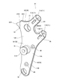
- FIG. 2 is a side view of the body frame 2 of the motorcycle 1.
- the symbol L1 is the axis of the head pipe 11.
- the head pipe 11 is disposed so as to incline rearwardly at the vehicle width direction center of the front portion of the vehicle, and supports a pair of left and right front forks 20 (see FIG. 1) so as to be steerable left and right.
- a front wheel 21 is rotatably supported at the lower part of the front forks 20, and a steering handle 22 is supported at the upper part of the front forks 20. That is, the head pipe 11 supports a steering device that constitutes the steering system of the motorcycle 1.
- the pair of left and right main frames 12 extend rearward and downward from the left and right sides of the lower portion of the head pipe 11, extend outward in the vehicle width direction, and extend rearward.
- the left and right main frames 12 are frames that support an engine 23 that is an internal combustion engine, an air cleaner 24, a storage box 25, and the like.
- the air cleaner 24 is supported in a posture inclined upward and rearward in parallel with the axis L ⁇ b> 1 of the head pipe 11 above the front portions of the left and right main frames 12, and is opened on the rear upper side.
- a case 24A and an air cleaner upper cover 24B that covers the open surface of the air cleaner lower case 24A are provided, and a duct 24D for introducing outside air is provided in the air cleaner upper cover 24B.
- the storage box 25 is supported by the rear of the air cleaner 24 and above the rear portions of the left and right main frames 12, and rotates the lid member 26 that covers the upper opening of the storage box 25 so that it can be opened and closed. Supports freely.
- the engine 23 is supported below the left and right main frames 12, behind the left and right down frames 13, and in front of the pivot frame 14.
- the left and right pivot frames 14 extend downward from a connecting portion with the rear portion (main frame rear portion) 12 ⁇ / b> R (see FIG. 2) of the left and right main frames 12, and support that is an upper and lower intermediate portion thereof.
- the pivot shaft 31 penetrates and is supported by the portion 14A.
- the pivot shaft 31 is arranged in parallel to the vehicle width direction, and a rear arm (also referred to as “swing arm”) 28 that supports the rear wheel 27 (see FIG. 1) on the rear portion via the pivot shaft 31 (also referred to as “swing arm”). Is supported so as to be swingable up and down.
- the left and right pivot frames 14 are provided with cross pipes 32 and 33 extending in the vehicle width direction above and below the pivot shaft 31.
- An upper end portion of a single rear cushion 35 (see FIG. 1) is rotatably connected to the upper cross pipe 32 via an upper cushion support portion provided at the center in the vehicle width direction.
- the lower end portion of the rear cushion 35 is connected to the rear arm 28 via a link mechanism 36 (see FIG. 1).
- the lower cross pipe 33 is provided with an engine hanger 33A that extends forward from the cross pipe 33 and supports the rear lower portion of the engine 23, and extends rearward from the cross pipe 33 to support the link mechanism 36.
- a link support portion 33B is provided.
- a step holder 37 is attached to the left and right pivot frames 14 on the outer side in the vehicle width direction (see FIG. 1).
- the step holder 37 extends rearward from the pivot frame 14, and a main step 38 on which the driver puts his / her foot is attached to the front portion of the step holder 37, and the passenger puts his / her foot on the rear portion of the step holder 37.
- a placing pillion step 39 is attached.
- the seat rail 15 and the back stay 16 are connected to each other in parallel with each other at the rear upper part of these pivot frames 14 (see FIG. 2). As shown in FIG. 2, the seat rail 15 is welded to the pivot frame 14, and the seat rail front portion 15 ⁇ / b> F linearly extending rearward and upward from the pivot frame 14 and the rear portion of the seat rail extending rearward and upward from the seat rail front portion 15 ⁇ / b> F. 15R.
- the back stay 16 is welded to the pivot frame 14 below the seat rail 15, and extends back linearly from the pivot frame 14 to the rear upper side, and extends linearly from the back stay front portion 16F to the rear upper side. It has a back stay rear portion 16R that is bent upward and is welded to the seat rail rear portion 15R.
- the back stay front portion 16F of the back stay 16 extends linearly rearward and upward with an inclination parallel to the seat rail front portion 15F.
- the left and right seat rails 15 and the back stay 16 constitute the rear frame 17 of the motorcycle 1.
- the back stay 16 can suppress the bending of the seat rail 15 and increase the frame rigidity.
- the seat rail 15 supports the occupant seat 41 and supports the fuel tank 42 below the occupant seat 41.
- the seat rail 15 supports the rear fender 43, the rear lights 44, and the like behind the occupant seat 41.
- the passenger seat 41 is formed into a long seat before and after the driver seat and the passenger seat are integrated, and the storage box 25 is disposed adjacent to the front of the passenger seat 41.
- an engine 23 is disposed at the center of the front and rear of the body frame 2
- a large capacity storage box 25 is disposed above the engine 23, and a fuel tank 42 is disposed behind the storage box 25. Therefore, relatively heavy parts (engine 23, fuel tank 42 in which fuel is stored, storage box 25 in which stored items are loaded) can be placed near the front and rear of the vehicle, and mass can be concentrated. Can do.
- the left and right down frames 13 extend linearly downward from a front portion (referred to as “main frame front portion”) 12 ⁇ / b> F of the main frame 12, and then bend backward to be pivot frames. 14.
- a single gusset plate 46 is provided in a portion from the lower part of the head pipe 11, which is the front lower part of the vehicle body frame 2, to the down frame 13.
- the gusset plate 46 is a substantially U-shaped metal plate-like part extending from the head pipe 11 to the pair of left and right down frames 13.
- the gusset plate 46 covers the connecting portion between the head pipe 11 and the main frame 12 from below.
- 46 A of 1 cover part, the 2nd cover part 46B of the right and left which covers the connection part of the main frame 12 and the down frame 13 from the front lower part continuously from the 1st cover part 46A, and it extends below from the 2nd cover part 46B
- the left and right third cover portions 46C extending to the middle position of the down frame 13 are integrally provided.
- the peripheral edges of the first to third cover portions 46A to 46C are joined to the head pipe 11, the main frame 12, and the down frame 13 by continuous welding. Accordingly, the connecting portions of the head pipe 11, the main frame 12, and the down frame 13 can be reinforced by the single gusset plate 46, and the rigidity of the vehicle body frame 2 can be increased.
- the engine 23 is a parallel two-cylinder four-cycle engine having a cylinder portion 52 that inclines upward from the front upper portion of the crankcase 51.
- the front portion of the crankcase 51 is supported on the down frame 13 via an engine hanger (not shown), and the upper portion of the crankcase 51 is supported on the main frame 12 via an engine hanger 47 B.
- the rear portion is supported by the cross pipe 33 between the pivot frames 14 via an engine hanger 33A (see FIG. 2).
- the cylinder part 52 includes a cylinder block 52A connected to the front upper part of the crankcase 51, a cylinder head 52B connected to the upper part of the cylinder block 52A, and a cylinder head cover 52C covering the upper part of the cylinder head 52B.
- An engine output shaft 51 ⁇ / b> A is provided at the left rear portion of the crankcase 51 of the engine 23.
- the engine output shaft 51 ⁇ / b> A and the rear wheel 27 are coupled via a drive chain (referred to as “chain”) 55 so that power can be transmitted, and the power of the engine 23 is transmitted to the rear wheel 27 via the chain 55.
- An air cleaner 24 is connected to the rear surface of the cylinder portion 52 of the engine 23 via the throttle body 30.
- the engine intake system including the throttle body 30 and the air cleaner 24 is centrally disposed on the front upper side of the engine 23.
- an exhaust pipe 56 is connected to the front surface of the cylinder portion 52, and the exhaust pipe 56 extends downward from the cylinder portion 52 and then bends backward to extend rearward through the left side of the engine 23. And the rear wheel 27 extend to the opposite side (right side) in the vehicle width direction and are connected to the muffler 57.
- the exhaust pipe 56 and the muffler 57 constitute an engine exhaust system.
- a catalytic converter 58 is provided in the middle of the exhaust pipe 56.
- This catalytic converter 58 is provided in the vicinity of the inlet of the exhaust pipe 56 (in the vicinity of the cylinder portion 52) and in the lower left part of the engine 23, whereby high-temperature exhaust immediately after being discharged from the cylinder portion 52 to the catalytic converter 58. While flowing the gas, the catalytic converter 58 and the muffler 57 can be arranged on the left and right.
- the engine 23 is a water-cooled engine, and a radiator 59 that cools engine coolant is supported on the vehicle body frame 2 (down frame 13) in front of the cylinder portion 52 (see FIG. 1). .
- a layout in which the seat rail 15 that is a rear pipe and the back stay 16 are connected to the rear portion of the pivot frame 14 and the distance between the seat rail 15 and the back stay 16 is reduced ( (See FIG. 2).
- a seat load which is a load from the passenger seat 41 side, acts as a tensile load on the upper side of each rear pipe (seat rail 15, back stay 16), and each rear pipe (seat rail 15, back stay 16).
- 16) Acts as a compressive load on the lower side. For this reason, there is a risk of receiving a large bending moment at the connecting portion between the rear pipe and the pivot frame 14. Therefore, in this configuration, a long hole 71 (see FIG. 2) that is a hole along the axis of each rear pipe (seat rail 15, backstay 16) is provided on the side surface of the pivot frame 14, and the peripheral edge ( The inner peripheral edge) is welded to the rear pipe.
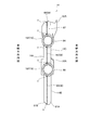
- FIG. 3 is a perspective view of the pivot frame 14, FIG. 4 is a side view, and FIG. 5 is a rear view.
- the left and right pivot frames 14 have a symmetrical shape
- FIGS. 3 to 5 show the right pivot frame 14.
- the pivot frame 14 has two press-molded plate members (plate-like members), the front-side pivot frame half 81A and the back-side pivot frame half 81B in the middle. These are vertically long hollow parts (hollow box-shaped members) in which the outer peripheral edges W, which are the open end edges of the halves 81A and 81B, are welded together.
- the outer shape of the front side pivot frame half body 81A is slightly larger than the outer shape of the rear side pivot frame half body 81B, and the rear side pivot frame half body 81B fits inside the larger front side pivot frame half body 81A, making it easy for each other. Can be aligned. Further, since the outer shape of the front side pivot frame half 81A is larger than the outer shape of the back side pivot frame half 81B, as shown in FIG. 5, the welded portions of these outer peripheral edges W (indicated by symbol Y in FIG. 5). Can be prevented from being exposed to the outside in the vehicle width direction.
- the pivot frame 14 is integrally provided with a support portion 14A that supports the pivot shaft 31, a lower extension portion 14B that extends downward from the support portion 14A, and an upper extension portion 14C that extends upward from the support portion 14A.
- the support portion 14A is provided with a through hole 75 through which the collar 31A (see FIG. 3) for inserting the pivot shaft 31 is inserted, and the downward extension portion 14B has a through hole 76 through which the lower cross pipe 33 passes.
- a through hole 77 through which the upper cross pipe 32 passes is provided in the upper extending portion 14C.
- the through holes 76 and 77 for the cross pipes 32 and 33 are provided so as to sandwich the pivot frame 14 so as to sandwich the pivot frame 14, the cross pipes 32 and 33 are separated from each other in the vertical direction to be bridged between the pivot frames 14. Therefore, the frame rigidity of the left and right pivot frames 14 can be increased efficiently.
- a front cylindrical portion 82 serving as a main frame insertion opening through which the main frame 12 is inserted is integrally provided at the front upper portion of the upward extending portion 14C.
- the front cylindrical portion 82 has a cylindrical shape extending forward from the cross pipe 32, the main frame rear portion 12R is inserted from the front, and the outer peripheral surface of the main frame rear portion 12R and the outer edge of the front cylindrical portion 82 are continuously welded. As a result, the front cylindrical portion 82 and the main frame 12 are joined.
- the cross pipe 32 is provided at a position where the shaft 77 ⁇ / b> L passes on the axis 82 ⁇ / b> L of the front cylindrical portion 82.
- the cross pipe 32 can efficiently increase the rigidity of the entire front cylinder portion 82, and can effectively increase the rigidity of the joint portion of the main frame 12.
- the axis line 82L of the front side cylinder part 82 corresponds with the axis line 12L of the main frame rear part 12R.
- the front cylindrical portion 82 is provided with a front protruding portion 82A that protrudes forward on the outer side in the vehicle width direction, and the outer edge of the front protruding portion 82A is welded to the main frame 12, thereby ensuring a long welding length. As a result, the bonding strength can be increased.
- FIGS. 3 to 5 at the rear upper part of the upwardly extending portion 14C, there is a rear first tube portion 84 serving as a seat rail insertion opening portion through which the seat rail 15 is inserted, and the rear side first cylinder portion 84.
- a rear second cylindrical portion 86 serving as a backstay insertion opening through which the backstay 16 is inserted is provided integrally below the first cylindrical portion 84.
- the rear first cylinder part 84 has a cylindrical shape extending rearward and upward from the cross pipe 32, and the seat rail front part 15F is inserted from the rear upper part of the rear first cylinder part 84.
- the rear second cylindrical portion 86 has a cylindrical shape that extends rearward and upward in parallel with the rear first cylindrical portion 84 below the cross pipe 32 and the rear first cylindrical portion 84.
- the backstay front portion 16F is inserted from the rear upper side of the two cylinder portions 86. That is, as shown in FIG. 4, the axis line 84L of the rear first cylinder part 84 coincides with the axis line 15L of the seat rail front part 15F, and the axis line 86L of the rear second cylinder part 86 is the backstay front part 16F. It is formed so as to coincide with the axis 16L.
- the rear first cylindrical portion 84 and the rear second cylindrical portion 86 are provided with a pair of left and right elongated holes 71, and by continuously welding the inner peripheral edge of each elongated hole 71, While seat rail front part 15F is joined, back side 2nd cylinder part 86 and backstay front part 16F are joined. As shown in FIG. 4, the axis line 84L of the rear first cylinder part 84 and the axis line 86L of the rear second cylinder part 86 are formed in parallel. For this reason, the seat rail 15 and the back stay 16 are connected to each cylinder portion 84, in a state where the seat rail front portion 15F and the back stay front portion 16F are parallel, that is, in a state where the seat rail 15 and the back stay 16 are assembled. 86 can be assembled.
- the axis line 84L of the rear first tube portion 84 is formed so as to pass on the shaft 77L of the cross pipe 32 (see FIG. 4). For this reason, it becomes easy to reinforce the overall strength of the rear first cylindrical portion 84 by the cross pipe 32, and the rigidity of the joint portion between the pivot frame 14 and the seat rail 15F can be efficiently increased.
- the cross pipe 32 is between the rear first tube portion 84 and the front tube portion 82, the shaft 77 ⁇ / b> L is on the axis 84 ⁇ / b> L of the rear first tube portion 84, and the front tube portion. Since it is provided on the axial line 82L of 82, the strength of both the rear first cylindrical portion 84 and the front cylindrical portion 82 can be increased efficiently.
- the long hole 71 will be described in detail.
- the former is referred to as a long hole 71A and the latter is referred to as a long hole 71B.
- the long hole 71A is a pair of left and right holes formed on the outer side in the vehicle width direction and the inner side in the vehicle width direction of the first rear cylinder portion 84, and has the same shape and the same position in a side view. Formed. As shown in FIG.
- these long holes 71 ⁇ / b> A are positions overlapping with the seat rail front portion 15 ⁇ / b> F inserted into the rear first tube portion 84 in a side view, and along the shaft 15 ⁇ / b> L of the seat rail front portion 15 ⁇ / b> F.
- a through hole extending in the front-rear direction is formed.
- These long holes 71A are formed in holes whose peripheral length (that is, circumferential length) is longer than the circumferential length of the seat rail front portion 15F that is a pipe welded by the long hole 71A.
- the perimeter of each long hole 71A substantially coincides with the weld length of the long hole 71A, welding in the case where the outer periphery of the seat rail front portion 15F is continuously welded with only a single long hole 71A. It is possible to secure a weld length that is greater than or equal to the length, and the left and right elongated holes 71A can ensure a weld length that is twice or more.
- the long hole 71B is a lower hole part positioned below the long hole 71A of the rear first cylinder part 84, and as shown in FIG. And in the same shape and at the same position as viewed from the side. As shown in FIG. 4, these long holes 71B overlap with the back stay front portion 16F inserted into the rear second cylindrical portion 86 in a side view and along the axis 16L of the back stay front portion 16F. A through hole extending in the front-rear direction is formed.
- the long hole 71B is formed in a hole shape in which the peripheral length (that is, the peripheral length) is longer than the peripheral length of the backstay front portion 16F that is a pipe welded by the long hole 71B. This makes it possible to secure a weld length that is twice or more that of the case where the outer circumference of the backstay front portion 16F is continuously welded.
- the seat rail front portion 15F and the backstay front portion 16F are made of the same diameter pipe, and the long holes 71A and 71B are formed in the same shape.
- the long axis J1 and the short axis J2 of these long holes 71A and 71B are formed. Are the same length.
- step holder fastening portions 88 and 89 are provided on the support portion 14A of the pivot frame 14 at positions above and below the horizontal axis 31L passing through the pivot shaft 31, and the step holder fastening portions 88 and 89 include stepping portions.
- the holder 37 (see FIG. 1) is fixed via a fastening member (fastening bolt).
- the welded portion of the pivot frame 14 is the outer peripheral edge W.
- the outer peripheral edge W includes a front edge W1 corresponding to the front edge of the pivot frame 14, a rear edge W2 corresponding to the rear edge of the pivot frame 14, and a rear upper edge corresponding to the rear upper edge of the pivot frame 14. W3 and an upper edge portion W4 corresponding to the upper edge of the pivot frame 14.
- the front edge portion W1 corresponds to the outer peripheral edge W from the lower end of the front cylinder portion 82 to the lower end of the pivot frame 14, and the rear edge portion W2 is the rear second cylinder portion 86 from the lower end of the pivot frame 14.
- the rear upper edge portion W3 corresponds to the outer peripheral edge W from the lower end of the rear first tube portion 84 to the upper end of the rear second tube portion 86, and the upper edge portion W4.
- a through hole 90 that penetrates in the vertical direction and functions as a drain hole is provided at the boundary between the front edge portion W1 and the rear edge portion W2, which is the lowermost position of the pivot frame 14. For this reason, the water in the pivot frame 14 can be drained by the through hole 90.
- the long hole 71A provided on the outer side in the vehicle width direction of the rear first cylindrical portion 84 and the seat rail front portion 15F are welded, and the length provided on the outer side in the vehicle width direction of the rear second cylindrical portion 86.
- the hole 71B and the backstay front portion 16F are welded (third step).
- the long hole 71A provided on the inner side in the vehicle width direction of the rear first cylindrical portion 84 and the seat rail front portion 15F are welded, and the length provided on the inner side in the vehicle width direction of the rear second cylindrical portion 86.
- the hole 71B and the backstay front portion 16F are welded (fourth stroke)
- the upper edge W4 and the rear edge W2 of the pivot frame 14 are welded (fifth stroke).
- the front edge portion W1 and the rear upper edge portion W3 of the pivot frame 14 are joined, and the upper edge portion W4 and the rear edge portion W2 are not joined, and the rear frame assembly is subassembled. Since the seat rail 15 and the back stay 16 are inserted into the pivot frame 14, the seat rail 15 and the back stay 16 can be easily inserted into the pivot frame 14 even if there is an assembly error. In addition, after the seat rail 15 and the back stay 16 are joined to the pivot frame 14, the upper edge W4 and the rear edge W2 of the pivot frame 14 are joined, so that the seat rail 15 and the back stay 16 are well welded. It becomes possible to join the pivot frame with quality.
- the long hole 71A along the shaft 15L of the seat rail front portion 15F is provided on the side surface of the pivot frame 14, and the periphery of the long hole 71A is provided. Since the pivot frame 14 and the seat rail front portion 15F are welded, the side surfaces of the pivot frame 14 and the seat rail front portion 15F can be joined to each other, and it is easy to ensure a long welding length. In this case, since the welded portion between the pivot frame 14 and the seat rail front portion 15F extends along the shaft 15L at the intermediate position between the seat rail front portion 15F and the seat rail front portion 15F, the welded portion is resistant to the bending moment in the vertical direction of the seat rail front portion 15F.
- the seat load acts as a tensile load on the upper side of the seat rail front portion 15F and acts as a compressive load on the lower side, and therefore acts as a bending moment in the vertical direction of the seat rail front portion 15F.
- the bonding strength strong against the bending moment can be efficiently secured, the bending strength against the sheet load can be easily secured.
- the pivot frame 14 is configured by joining the outer peripheral edges W of the front-side pivot frame half 81A and the back-side pivot frame half 81B, which are the left and right plates that are aligned in the middle.
- the left and right pivot frame halves 81A and 81B are provided with a rear first tube portion 84 serving as a seat rail insertion opening at the upper rear of the pivot frame 14, and a long hole 71A is formed between the left and right pivot frame halves 81A and 81B. Since the pivot frame 14 is closed, the rigidity of the pivot frame 14 is increased, and the joint strength can be increased by welding both the left and right sides of the seat rail 15.
- a backstay 16 is provided below the seat rail 15 at both ends joined to the rear portion of the pivot frame 14 and the rear portion of the seat rail 15, and the backstay is located below the rear first tube portion 84 of the pivot frame 14.
- a rear second cylindrical portion 86 serving as an insertion opening is provided, and a long hole 71B, which is a lower hole along the shaft 16L of the backstay front portion 16F, is provided on the side surface of the rear second cylindrical portion 86. Since the pivot frame 14 and the back stay front portion 16F are welded at the periphery of the hole 71B, the back stay 16 that suppresses the deflection of the seat rail 15 has a welding structure similar to that of the seat rail 15 and has a bending strength with respect to the seat load. Can be secured more easily.
- the seat rail front portion 15F and the back stay front portion 16F are pipe-like, and the circumferences of the long holes 71A and 71B are equal to or greater than the circumferences of the seat rail front portion 15F and the back stay front portion 16F. Since it is formed in a long hole, it is possible to ensure a long weld length and to easily secure the joint strength.
- the above-described embodiment is merely an aspect of the present invention, and can be arbitrarily modified and applied without departing from the gist of the present invention.
- the present invention is applied to the frame structure in which the seat rail 15 and the backstay 16 are welded to the rear portion of the pivot frame 14 has been described.
- the present invention can be widely applied to a frame structure in which the rail 15 is welded.
- the present invention is possible in addition to the connecting portion of the pivot portion, that is, a hollow box-like member is provided by bending the end portions of a pair of plate-like members and welding the end portions, and the box.
- the present invention can be applied to a frame structure formed by welding a plurality of pipes to a shaped member.
- a hole is provided on the side surface of the box-shaped member along the axis of the pipe, and the box-shaped member and the pipe are welded at the periphery of the hole by welding the box-shaped member and the pipe.
- the load that the portion receives due to the bending moment can be made as small as possible, and the bending strength can be easily secured.
- the present invention is applied to the frame structure of the motorcycle 1 shown in FIG. 1 .
- the present invention is not limited to this, and the present invention can be widely applied to the frame structure of a saddle-ride type vehicle.
- the saddle-ride type vehicle includes all vehicles that ride on the vehicle body, and includes not only motorcycles (including bicycles with motors) but also three-wheeled vehicles and four-wheeled vehicles classified as ATVs (rough terrain vehicles). It is a vehicle including.
Abstract
Description
この特許文献1には、ヘッドパイプと、該ヘッドパイプから後ろ下がりに延びるメインパイプと、メインパイプの後部に溶接されて後方に延びる左右一対のセンターアッパーパイプと、センターアッパーパイプから下方に延びるセンターパイプと、センターアッパーパイプの後端に前端上部が溶接されて後方に延びるシートレールと、シートレールの前端下部から下方に延びるリヤパイプと、リヤパイプの下部に連結される左右一対のピボットフレームとを有する小型車両のフレーム構造が開示されている。 A motorcycle has a frame structure in which a seat frame is welded to a rear portion of a pivot frame (see, for example, Patent Document 1).
This
このフレーム構造では、シート荷重が、リヤパイプとセンターアッパーパイプの両方に作用し、センターアッパーパイプとリヤパイプとの間に大きな間隔を設けることによって、シート荷重に対し車体フレームが十分な剛性を有する。従って、リヤパイプとピボットフレームとの溶接部の強度は確保される。 In this small vehicle, the pivot frame has a gusset shape, a rear pipe extending downward from the lower front end of the seat rail is provided, and the outer edge of the pivot frame and the peripheral surface of the rear pipe are welded.
In this frame structure, the seat load acts on both the rear pipe and the center upper pipe, and the vehicle body frame has sufficient rigidity with respect to the seat load by providing a large gap between the center upper pipe and the rear pipe. Therefore, the strength of the welded portion between the rear pipe and the pivot frame is ensured.
この場合、ピボットフレームとリヤパイプとの溶接部に作用する曲げ応力が大きくなり、リヤパイプ上前面の溶接部は大きな引っ張り応力を受け、リヤパイプ下後面の溶接部は大きな圧縮応力を受ける。特に、ピボットフレームが左右割りの最中状である場合、リヤパイプを挿通する開口部の上部と下部とに隙間ができ、この隙間部でピボットフレームとリヤパイプとを溶接することが困難である。
このような場合、シート荷重によって溶接部に大きなモーメントを受けると、強度の確保が難しくなる場合がある。 However, the frame structure without the member for connecting the seat rail and the main frame (the rear part of the center upper pipe in Patent Document 1), and the rear part of the pivot frame, the distance between the seat rail and the back stay constituting the rear pipe is set. In the case of a narrow frame structure, it becomes difficult to ensure the rigidity of the vehicle body frame against the seat load.
In this case, the bending stress acting on the welded portion between the pivot frame and the rear pipe is increased, the welded portion on the upper front surface of the rear pipe is subjected to a large tensile stress, and the welded portion on the lower rear surface of the rear pipe is subjected to a large compressive stress. In particular, when the pivot frame is in the middle of the left and right splits, a gap is formed between the upper part and the lower part of the opening through which the rear pipe is inserted, and it is difficult to weld the pivot frame and the rear pipe at this gap part.
In such a case, if a large moment is applied to the weld due to the seat load, it may be difficult to ensure the strength.
この構成によれば、ピボットフレームの側面に、シートレールの前部の軸に沿う孔部を設け、当該孔部の周縁にて、ピボットフレームとシートレールの前部とを溶接するので、ピボットフレームとシートレールとの溶接部が、シートレールの上下中間位置に設けられ、シート荷重による曲げモーメントに強い接合強度を効率よく確保でき、曲げ強度を容易に確保できるようになる。 In order to solve the above-described problems, the present invention provides a pivot frame (14) that swingably supports a rear arm (28) that pivotally supports a rear wheel (27) at a rear portion, and a rear portion of the pivot frame (14). In a frame structure of a saddle-ride type vehicle having a seat rail (15) that is welded and extends rearward and upward, a hole portion along a front axis of the seat rail (15) is formed on a side surface of the pivot frame (14). 71A), and the pivot frame (14) and the front portion of the seat rail (15) are welded at the periphery of the hole (71A).
According to this configuration, since the hole along the axis of the front part of the seat rail is provided on the side surface of the pivot frame, and the pivot frame and the front part of the seat rail are welded at the periphery of the hole, the pivot frame The seat rail is welded to the seat rail at an upper and lower intermediate position, so that it is possible to efficiently secure a strong joint strength against a bending moment caused by the seat load, and to easily secure the bending strength.
この構成によれば、ピボットフレームを閉断面化することでピボットフレームの剛性を高めつつ、シートレールの左右両方を溶接することで接合強度を高めることができる。 In the above configuration, the pivot frame (14) is configured by joining open end edges (W) of the left and right plate portions (81A, 81B) that are matched in the middle, and the left and right plate portions (81A, 81B). 81B), a seat rail insertion opening (84) is provided on the rear upper side of the pivot frame (14), and the hole (71A) is provided in both the left and right plate parts (81A, 81B). May be.
According to this configuration, it is possible to increase the joint strength by welding both the left and right of the seat rail while increasing the rigidity of the pivot frame by making the pivot frame closed.
この構成によれば、ピボットフレームのバックステー挿通開口部の側面に、バックステーの前部の軸に沿う下側孔部を設け、当該下側孔部の周縁にて、ピボットフレームとバックステーの前部とを溶接するので、シートレールの撓みを抑えるバックステーについても、シートレールと同様の溶接構造とし、シート荷重に対する曲げ強度をより容易に確保し易くできる。 In the above-described configuration, the back stay (16) is joined to the rear part of the pivot frame (14) below the seat rail (15), extends rearward and upward, and is joined to the rear part of the seat rail (15). ), A back stay insertion opening (86) is provided below the seat rail insertion opening (84) of the pivot frame (14), and the back stay insertion opening (86) is provided on a side surface of the back stay insertion opening (86). A lower hole (71B) is provided along the front shaft (16L) of the stay (16), and the pivot frame (14) and the back stay (16) are provided at the periphery of the lower hole (71B). The front part may be welded.
According to this configuration, the lower hole portion along the axis of the front portion of the back stay is provided on the side surface of the back stay insertion opening portion of the pivot frame, and the pivot frame and the back stay are arranged at the periphery of the lower hole portion. Since the front part is welded, the back stay that suppresses the deflection of the seat rail can be made to have the same welded structure as the seat rail, and the bending strength against the seat load can be easily secured.
この構成によれば、左右のピボットフレーム間のクロスパイプが、シートレールの前部の軸上で前下方に隣接して設けられるので、シートレールの接合部周辺のピボットフレームの剛性をより高めることができる。 In the above configuration, the pivot frame (14) is provided in a pair of left and right, a cross pipe (32) is provided between the left and right pivot frames (14), and the cross pipe (32) is connected to the seat rail (15). ) May be provided adjacent to the front lower side on the front shaft (15L).
According to this configuration, since the cross pipe between the left and right pivot frames is provided adjacent to the front lower side on the front shaft of the seat rail, the rigidity of the pivot frame around the joint portion of the seat rail is further increased. Can do.
この構成によれば、シートレールとバックステーとを組んだ状態で、左右のピボットフレームに挿入して溶接する場合に、組立誤差があっても、シートレールとバックステーとをピボットフレームに挿入し易く、かつ、シートレールとバックステーとを良好な溶接品質でピボットフレームに接合することができる。 In the above configuration, the front edge (W1) of the left and right plate portions (81A, 81B) and the edge (W3) between the seat rail insertion opening (84) and the backstay insertion opening (86). ), The assembly of the seat rail (15) and the back stay (16), the seat rail insertion opening (84) and the back stay insertion opening (86). ), The hole (71A) on the outer side in the vehicle width direction of the left and right plate portions (81A, 81B), and the seat rail (15) are welded, and the vehicle width direction A third step of welding the lower hole (71B) on the outside and the back stay (16), and the hole (71A) on the inner side in the vehicle width direction and the seat rail (15) are welded. Along with the front in the vehicle width direction A fourth step of welding the lower hole portion (71B) and the back stay (16), and a second step of welding the upper edge (W4) and the rear edge (W2) of the left and right plate portions (81A, 81B). It may be manufactured by the process of 5.
According to this configuration, when the seat rail and the back stay are assembled and inserted into the left and right pivot frames and welded, the seat rail and the back stay are inserted into the pivot frame even if there is an assembly error. It is easy and the seat rail and the backstay can be joined to the pivot frame with good welding quality.
この構成によれば、ピボットフレームとシートレールの前部とを溶接するための孔部を、その周長がシートレールの前部の周長以上の長孔であるため、溶接長を長く確保でき、接合強度をより確保し易くできる。 In the above configuration, the front portion of the seat rail (15) has a pipe shape, and the hole portion (71A) has a circumferential length equal to or greater than the circumferential length of the pipe at the front portion of the seat rail (15). It may be a long hole.
According to this configuration, the hole for welding the pivot frame and the front part of the seat rail is a long hole whose peripheral length is greater than or equal to the peripheral length of the front part of the seat rail, so that a long welding length can be secured. It is possible to easily secure the bonding strength.
また、上記構成において、前記孔部(71)は、前記パイプ(15,16)の軸と側面視で沿うような長孔としてもよい。この構成によれば、溶接長を長くでき、溶接部の強度を高めることができる。 Moreover, this invention provides a hollow box-shaped member (14) by bending the edge part of a pair of plate-shaped member (81A, 81B), and welding the edge part, The box-shaped member (14) is provided. In a frame structure of a saddle-ride type vehicle formed by welding a plurality of pipes (15, 16), openings (84, 86) through which the pipes (15, 16) are inserted into the box-shaped member (14). And provided with a hole (71) along the axis of the pipe (15, 16) on a side surface overlapping the pipe (15, 16) through which the box-shaped member (14) is inserted. The box-like member (14) and the pipes (15, 16) are welded at the periphery of (71). According to this structure, the load which the welding part of a box-shaped member and a pipe receives by bending moment can be made as small as possible, and bending strength can be ensured easily.
Moreover, the said structure WHEREIN: The said hole (71) is good also as an elongate hole which follows the axis | shaft of the said pipe (15,16) in side view. According to this configuration, the weld length can be increased and the strength of the welded portion can be increased.
また、ピボットフレームは、最中状に合わせられる左右の板部の開放端縁同士を接合して構成され、左右の板部によって、ピボットフレームの後上方にシートレール挿通開口部を設け、孔部が、左右の板部の両方に設けられるようにすれば、ピボットフレームを閉断面化することでピボットフレームの剛性を高めつつ、シートレールの左右両方を溶接することで接合強度を高めることができる。 In the present invention, a hole along the axis of the front part of the seat rail is provided on the side surface of the pivot frame, and the pivot frame and the front part of the seat rail are welded at the periphery of the hole part. With the configuration in which the seat rail is welded, the bending strength of the welded portion can be easily secured.
Further, the pivot frame is configured by joining the open end edges of the left and right plate portions that are adjusted in the middle, and the left and right plate portions are provided with seat rail insertion openings at the upper rear of the pivot frame, and the hole portions. However, if it is provided on both the left and right plate parts, it is possible to increase the joint strength by welding both the left and right seat rails while increasing the rigidity of the pivot frame by closing the pivot frame. .
また、ピボットフレームは、左右一対設けられ、当該左右のピボットフレーム間にクロスパイプを設け、クロスパイプは、シートレールの前部の軸)上で前下方に隣接して設けられるようにすれば、シートレールの接合部周辺のピボットフレームの剛性をより高めることができる。 Also, a lower hole along the front axis of the back stay is provided on the side of the back stay insertion opening of the pivot frame, and at the periphery of the lower hole, the pivot frame and the front of the back stay are connected. If the welding is performed, the back stay that suppresses the bending of the seat rail can be made to have the same welded structure as the seat rail, and the bending strength against the seat load can be easily secured.
Also, the pivot frame is provided as a pair of left and right, a cross pipe is provided between the left and right pivot frames, and the cross pipe is provided adjacent to the front lower side on the front rail of the seat rail. The rigidity of the pivot frame around the joint portion of the seat rail can be further increased.
また、一対の板状部材の端部を折り曲げて、その端部を溶接することにより中空の箱状部材を設け、その箱状部材に複数のパイプを溶接して成形される鞍乗り型車両のフレーム構造で、箱状部材に、パイプが挿通される開口を設け、箱状部材の挿通されたパイプと重なり合う側面に、パイプの軸と沿うような孔部を設け、当該孔部の周縁にて、箱状部材とパイプとを溶接したため、箱状部材とパイプとの溶接部が、曲げモーメントによって受ける荷重を極力小さくでき、曲げ強度を容易に確保することができる。
この場合、孔部は、パイプの軸と側面視で沿うような長孔とすれば、溶接長を長くでき、溶接部の強度を高めることができる。 In addition, the front part of the seat rail is pipe-shaped, and the hole part can ensure a long welding length if the peripheral length is longer than the peripheral length of the pipe at the front part of the seat rail. It is possible to easily secure the bonding strength.
Further, a saddle-ride type vehicle formed by bending the ends of a pair of plate-like members and welding the ends to provide a hollow box-like member and welding a plurality of pipes to the box-like member. In the frame structure, an opening through which the pipe is inserted is provided in the box-shaped member, and a hole along the axis of the pipe is provided on a side surface overlapping with the pipe through which the box-shaped member is inserted. Since the box-shaped member and the pipe are welded, the load received by the bending moment at the welded portion between the box-shaped member and the pipe can be minimized, and the bending strength can be easily ensured.
In this case, if the hole is a long hole along the axis of the pipe in a side view, the weld length can be increased and the strength of the weld can be increased.
図1は、本発明の実施形態に係る自動二輪車1の左側面図である。
この自動二輪車1の車体フレーム2は、複数種の金属部品を溶接等により一体に結合してなり、ヘッドパイプ11と、ヘッドパイプ11から後下方に延出する左右一対のメインフレーム12と、メインフレーム12から下方に延びてエンジン23の前端部を支持する左右一対のダウンフレーム(「クレードルフレーム」とも言う)13と、メインフレーム12の後端部に連結される左右一対のピボットフレーム14と、ピボットフレーム14後部に連結されて後上方に延びる左右一対のシートレール15と、ピボットフレーム14とシートレール15との間を架橋するバックステー16とを備えている。 Hereinafter, an embodiment of the present invention will be described with reference to the drawings. In the description, descriptions of directions such as front and rear, right and left and up and down are the same as directions with respect to the vehicle body unless otherwise specified.
FIG. 1 is a left side view of a
The
ヘッドパイプ11は、車両前部の車幅方向中心で後上がりに傾斜して配置され、左右一対のフロントフォーク20(図1参照)を左右に操舵自在に支持する。図1に示すように、これらフロントフォーク20の下部には、前輪21が回転自在に支持され、これらフロントフォーク20の上部には、操舵用のハンドル22が支持される。すなわち、ヘッドパイプ11は、自動二輪車1の操舵系を構成する操舵装置を支持している。 FIG. 2 is a side view of the
The
左右のメインフレーム12は、内燃機関であるエンジン23、エアクリーナ24及び収納ボックス25等を支持するフレームである。図1に示すように、エアクリーナ24は、左右のメインフレーム12の前部上方にて、ヘッドパイプ11の軸線L1と平行に後上がりに傾斜した姿勢で支持され、後上方に開口するエアクリーナ下側ケース24Aと、エアクリーナ下側ケース24Aの開放面を覆うエアクリーナ上側カバー24Bとを備え、エアクリーナ上側カバー24Bに外気導入用のダクト24Dを設けている。 The pair of left and right
The left and right
エンジン23は、左右のメインフレーム12の下方、左右のダウンフレーム13の後方かつピボットフレーム14の前方に支持され、これによって、車体フレーム2の前後中央下部に懸架される。 As shown in FIG. 1, the
The
また、下側のクロスパイプ33には、このクロスパイプ33から前方に延びてエンジン23の後下部を支持するエンジンハンガ33Aが設けられるとともに、クロスパイプ33から後方に延びてリンク機構36を支持するリンク支持部33Bが設けられる。 An upper end portion of a single rear cushion 35 (see FIG. 1) is rotatably connected to the
The
図2に示すように、シートレール15は、ピボットフレーム14に溶接され、ピボットフレーム14から後上方へ直線状に延びるシートレール前部15Fと、シートレール前部15Fから後上方へ延びるシートレール後部15Rとを有している。 The
As shown in FIG. 2, the
このようにして、左右のシートレール15とバックステー16とで自動二輪車1のリヤフレーム17が構成される。このリヤフレーム17では、シートレール15とピボットフレーム14との間をバックステー16が架橋するので、バックステー16によりシートレール15の撓みを抑えることができ、フレーム剛性を高めることができる。 The
In this manner, the left and right seat rails 15 and the
この乗員用シート41は、運転者用シートと同乗者用シートとを一体にした前後に長いシートに形成され、この乗員用シート41の前方に収納ボックス25が隣接して配置される。
この自動二輪車1は、車体フレーム2の前後中央下部にエンジン23を配設し、このエンジン23の上方に大容量の収納ボックス25を配設し、この収納ボックス25の後方に燃料タンク42を配設するため、比較的重量を有する部品(エンジン23、燃料が貯留された燃料タンク42、収納物が積載された収納ボックス25)を車両前後中央に寄せて配置でき、マスの集中化を図ることができる。 As shown in FIG. 1, the
The
In the
図2に示すように、車体フレーム2の前下部であるヘッドパイプ11下部からダウンフレーム13に至る部分には、単一のガセットプレート46が設けられている。 As shown in FIGS. 1 and 2, the left and right down frames 13 extend linearly downward from a front portion (referred to as “main frame front portion”) 12 </ b> F of the
As shown in FIG. 2, a
これら第1~第3覆い部46A~46Cは、その周縁がヘッドパイプ11、メインフレーム12及びダウンフレーム13に連続溶接で接合される。これによって、この単一のガセットプレート46によってヘッドパイプ11、メインフレーム12及びダウンフレーム13の各連結部を補強でき、車体フレーム2の剛性を高めることができる。 The
The peripheral edges of the first to
このエンジン23は、クランクケース51の前部がダウンフレーム13にエンジンハンガ(不図示)を介して支持され、クランクケース51の上部がメインフレーム12にエンジンハンガ47Bを介して支持され、クランクケース51の後部がピボットフレーム14間のクロスパイプ33にエンジンハンガ33A(図2参照)を介して支持される。
シリンダ部52は、クランクケース51の前上部に連結されるシリンダブロック52Aと、シリンダブロック52Aの上部に連結されるシリンダヘッド52Bと、シリンダヘッド52Bの上部を覆うシリンダヘッドカバー52Cとを備えている。 As shown in FIG. 1, the
In the
The
エンジン23のシリンダ部52背面には、スロットルボディ30を介してエアクリーナ24が接続される。これによって、スロットルボディ30やエアクリーナ24からなるエンジン吸気系が、エンジン23の前上方に集約して配設される。
また、シリンダ部52前面には、排気管56が接続され、この排気管56は、シリンダ部52から下方に延びた後に後方に屈曲してエンジン23の左側方を通って後方へ延び、エンジン23と後輪27との間を車幅方向反対側(右側)へ延びてマフラー57に接続される。この排気管56とマフラー57とによってエンジン排気系が構成される。 An
An
Further, an
また、このエンジン23は、水冷式のエンジンであり、エンジン冷却水を冷却するラジエータ59を、シリンダ部52の前上方にて車体フレーム2(ダウンフレーム13)に支持している(図1参照)。 A
The
このフレームレイアウトの場合、乗員用シート41側からの荷重であるシート荷重が、各々のリヤパイプ(シートレール15、バックステー16)上側に引っ張り荷重として作用し、各々のリヤパイプ(シートレール15、バックステー16)下側に圧縮荷重として作用する。このため、リヤパイプとピボットフレーム14との連結部に大きな曲げモーメントを受けるおそれがある。
そこで、本構成では、ピボットフレーム14の側面に、各リヤパイプ(シートレール15、バックステー16)の軸に沿う孔部である長孔71(図2参照)を設け、各長孔71の周縁(内周縁)をリヤパイプに各々溶接するようにしている。 By the way, in the
In the case of this frame layout, a seat load, which is a load from the
Therefore, in this configuration, a long hole 71 (see FIG. 2) that is a hole along the axis of each rear pipe (
図3~図5に示すように、ピボットフレーム14は、2枚のプレス成形された板材(板状部材)である表側ピボットフレーム半体81Aと裏側ピボットフレーム半体81Bとを最中状に合わせ、各半体81A,81Bの開放端縁である外周縁W同士を溶接して一体に結合した縦長の中空部品(中空の箱状部材)である。
この表側ピボットフレーム半体81Aの外形は、裏側ピボットフレーム半体81Bの外形よりも若干大きく形成され、大きい側の表側ピボットフレーム半体81Aの内側に裏側ピボットフレーム半体81Bが嵌り、互いを容易に位置合わせ可能である。また、表側ピボットフレーム半体81Aの外形が、裏側ピボットフレーム半体81Bの外形よりも大きいので、図5に示すように、これらの外周縁Wの溶接箇所(図5中、符号Yで示す)を、車幅方向外側に露出しないようにすることができる。 3 is a perspective view of the
As shown in FIGS. 3 to 5, the
The outer shape of the front side pivot
支持部14Aには、ピボット軸31挿入用のカラー31A(図3参照)を挿通する貫通孔75が設けられ、下方延出部14Bには、下側のクロスパイプ33が貫通する貫通孔76が設けられ、上方延出部14Cには、上側のクロスパイプ32が貫通する貫通孔77が設けられる。
このように、ピボットフレーム14を挟むように上下に間隔を空けてクロスパイプ32,33用の貫通孔76,77を設けるので、クロスパイプ32,33を上下に離してピボットフレーム14間に架橋させることができ、左右のピボットフレーム14のフレーム剛性を効率よく高めることができる。 The
The
As described above, since the through
図4に示すように、クロスパイプ32は、その軸77Lが前側筒部82の軸線82L上を通る位置に設けられる。このため、このクロスパイプ32によって前側筒部82全体の剛性を効率よく高めることが可能であり、メインフレーム12接合部の剛性を効率よく高めることができる。なお、前側筒部82の軸線82Lは、メインフレーム後部12Rの軸線12Lと一致する。
また、この前側筒部82には、車幅方向外側で前方に突出する前方突出部82Aが設けられ、この前方突出部82Aの外縁がメインフレーム12に溶接されることによって、溶接長が長く確保され、接合強度を高めることができる。 A front
As shown in FIG. 4, the
The front
後側第1筒部84は、クロスパイプ32から後上方に延びる筒形状を有し、この後側第1筒部84の後上方からシートレール前部15Fが挿入される。
また、後側第2筒部86は、クロスパイプ32及び後側第1筒部84の下方で、後側第1筒部84と平行に後上方に延びる筒形状を有し、この後側第2筒部86の後上方からバックステー前部16Fが挿入される。
つまり、図4に示すように、後側第1筒部84の軸線84Lは、シートレール前部15Fの軸線15Lと一致し、後側第2筒部86の軸線86Lは、バックステー前部16Fの軸線16Lと一致するように形成されている。 On the other hand, as shown in FIGS. 3 to 5, at the rear upper part of the upwardly extending
The rear
The rear second
That is, as shown in FIG. 4, the
図4に示すように、後側第1筒部84の軸線84Lと、後側第2筒部86の軸線86Lとは平行に形成される。このため、シートレール前部15Fとバックステー前部16Fとを平行にした状態、つまり、シートレール15とバックステー16とを組んだ状態で、シートレール15とバックステー16を各筒部84,86に組み付けることが可能である。 The rear first
As shown in FIG. 4, the
なお、本構成では、このクロスパイプ32が、後側第1筒部84と前側筒部82との間で、その軸77Lが後側第1筒部84の軸線84L上、かつ、前側筒部82の軸線82L上に設けられるので、後側第1筒部84と前側筒部82との両方の強度を効率よく高めることができる。 Furthermore, the
In this configuration, the
図3に示すように、長孔71Aは、後側第1筒部84の車幅方向外側と車幅方向内側とに形成される左右一対の孔部であり、側面視で同形状かつ同一位置に形成される。これら長孔71Aは、図4に示すように、後側第1筒部84に挿入されたシートレール前部15Fと側面視で重なる位置であって、シートレール前部15Fの軸15Lに沿って前後方向に延びる貫通孔に形成される。 Next, the
As shown in FIG. 3, the
より具体的には、シートレール前部15Fの周長が約90mmの場合には、長孔71Aの長軸J1を40mm、短軸J2を10mmに設定することによって、一つの長孔71Aで、この長孔71Aの周長とほぼ同等の溶接長(約100mm)を確保することができる。また、短軸J2を10mm程度以上確保することによって、長孔71A内に十分な溶接作業スペースを確保することができる。 These
More specifically, when the circumference of the seat
これら長孔71Bは、図4に示すように、後側第2筒部86に挿入されたバックステー前部16Fと側面視で重なる位置であって、バックステー前部16Fの軸16Lに沿って前後方向に延びる貫通孔に形成される。 The
As shown in FIG. 4, these
本構成では、シートレール前部15Fとバックステー前部16Fとを同径パイプとし、長孔71A,71Bを同一形状に形成しており、これら長孔71A,71Bの長軸J1及び短軸J2は同一長さとなっている。
また、ピボットフレーム14の支持部14Aには、ピボット軸31を通る水平軸線31Lに対して上下の位置にステップホルダ締結部88,89が設けられ、このステップホルダ締結部88,89には、ステップホルダ37(図1参照)が締結部材(締結ボルト)を介して固定される。 The
In this configuration, the seat
Further, step
このピボットフレーム14は、表側ピボットフレーム半体81Aと裏側ピボットフレーム半体81Bとを最中状に合わせて溶接するため、ピボットフレーム14の溶接部位は外周縁Wである。
この外周縁Wは、ピボットフレーム14の前縁に相当する前縁部W1と、ピボットフレーム14の後縁に相当する後縁部W2と、ピボットフレーム14の後上縁に相当する後上縁部W3と、ピボットフレーム14の上縁に相当する上縁部W4とで構成される。 Next, the welded part of the
Since the
The outer peripheral edge W includes a front edge W1 corresponding to the front edge of the
なお、このピボットフレーム14の最下端位置である前縁部W1と後縁部W2との境には、上下方向に貫通して水抜き孔として機能する貫通孔90が設けられている。このため、この貫通孔90によって、ピボットフレーム14内の水抜きが可能である。 More specifically, the front edge portion W1 corresponds to the outer peripheral edge W from the lower end of the
A through
ピボットフレーム14を溶接する場合、まず、ピボットフレーム14の前縁部W1と、後側第1筒部84と後側第2筒部86との間であるピボットフレーム14の後上縁部W3とを溶接する(第1の行程)。
また、左右のシートレール15とバックステー16とを組んでリヤフレーム17を構成するリヤフレーム組立体を予め製作しておき、第1の行程の後、このリヤフレーム組立体のシートレール前部15Fとバックステー前部16Fとを、ピボットフレーム14の後側第1筒部84と後側第2筒部86とに各々挿入した状態にセットする(第2の行程)。
次に、後側第1筒部84の車幅方向外側に設けた長孔71Aと、シートレール前部15Fとを溶接するとともに、後側第2筒部86の車幅方向外側に設けた長孔71Bとバックステー前部16Fとを溶接する(第3の行程)。 Next, a procedure for welding the
When the
In addition, a rear frame assembly constituting the
Next, the
この第1~第5の行程を順に行うことによって、ピボットフレーム14の外周縁Wの全ての溶接と、ピボットフレーム14へのシートレール15とバックステー16との接合とが行われる。 Subsequently, the
By sequentially performing the first to fifth strokes, all the outer peripheral edges W of the
また、シートレール15とバックステー16とをピボットフレーム14に接合した後に、ピボットフレーム14の上縁部W4と後縁部W2とを接合するので、シートレール15とバックステー16とを良好な溶接品質でピボットフレームに接合することが可能になる。 According to this welding procedure, the front edge portion W1 and the rear upper edge portion W3 of the
In addition, after the
この場合、ピボットフレーム14とシートレール前部15Fとの溶接部が、シートレール前部15Fの上下中間位置で軸15Lに沿って延びるので、シートレール前部15Fの上下方向への曲げモーメントに強い接合強度を確保し易くなる。
この自動二輪車1では、シート荷重がシートレール前部15Fの上側では引っ張り荷重として作用し、下側では圧縮荷重として作用するため、シートレール前部15Fの上下方向への曲げモーメントとして作用する。本構成では、この曲げモーメントに強い接合強度を効率よく確保できるので、シート荷重に対する曲げ強度を容易に確保することが可能である。 As described above, in the present embodiment, as shown in FIG. 4, the
In this case, since the welded portion between the
In the
また、本構成では、このピボットフレーム14の溶接を、上記第1~第5の行程順で行うので、シートレール15とバックステー16とを組んだ状態で、左右のピボットフレーム14に挿入して溶接する場合に、組立誤差があっても、シートレール15とバックステー16とをピボットフレーム14に挿入し易くなり、かつ、シートレール15とバックステー16とを良好な溶接品質でピボットフレームに接合することができる。 In this configuration, since the
Further, in this configuration, since the
例えば、上記実施形態では、ピボットフレーム14の後部にシートレール15とバックステー16とを溶接したフレーム構造に本発明を適用する場合を説明したが、これに限らず、ピボットフレーム14の後部にシートレール15を溶接したフレーム構造に本発明を広く適用可能である。 The above-described embodiment is merely an aspect of the present invention, and can be arbitrarily modified and applied without departing from the gist of the present invention.
For example, in the above-described embodiment, the case where the present invention is applied to the frame structure in which the
また、上記孔部を、上記パイプの軸と側面視で沿うような長孔にすることによって、溶接長を長くでき、溶接部の強度を高めることができる。
また、上記実施形態では、図1に示す自動二輪車1のフレーム構造に本発明を適用する場合を説明したが、これに限らず、鞍乗り型車両のフレーム構造に本発明を広く適用可能である。なお、鞍乗り型車両とは、車体に跨って乗車する車両全般を含み、自動二輪車(原動機付き自転車も含む)のみならず、ATV(不整地走行車両)に分類される三輪車両や四輪車両を含む車両である。 Further, the present invention is possible in addition to the connecting portion of the pivot portion, that is, a hollow box-like member is provided by bending the end portions of a pair of plate-like members and welding the end portions, and the box. The present invention can be applied to a frame structure formed by welding a plurality of pipes to a shaped member. In this case, a hole is provided on the side surface of the box-shaped member along the axis of the pipe, and the box-shaped member and the pipe are welded at the periphery of the hole by welding the box-shaped member and the pipe. The load that the portion receives due to the bending moment can be made as small as possible, and the bending strength can be easily secured.
Moreover, by making the hole into a long hole along the axis of the pipe in a side view, the weld length can be increased and the strength of the weld can be increased.
In the above embodiment, the case where the present invention is applied to the frame structure of the
2 車体フレーム
14 ピボットフレーム
15 シートレール
15F シートレール前部
15R シートレール後部
16 バックステー
16F バックステー前部
27 後輪
28 リヤアーム
32,33 クロスパイプ
71 長孔
71A 長孔(孔部)
71B 長孔(下側孔部)
81A 表側ピボットフレーム半体
81B 裏側ピボットフレーム半体
82 前側筒部
82A 前方突出部
84 後側第1筒部(シートレール挿通開口部)
86 後側第2筒部(バックステー挿通開口部)
W 外周縁(開放端縁)
W1 前縁部
W2 後縁部
W3 後上縁部
W4 上縁部 1 Motorcycle (saddle-ride type vehicle)
2
71B Long hole (lower hole)
81A Front side pivot
86 Rear second cylinder (back stay insertion opening)
W Outer rim (open edge)
W1 Front edge W2 Rear edge W3 Rear upper edge W4 Upper edge
Claims (8)
- 後部に後輪(27)を軸支するリヤアーム(28)を揺動自在に支持するピボットフレーム(14)と、当該ピボットフレーム(14)の後部に溶接され、後上方に延びるシートレール(15)とを有する鞍乗り型車両のフレーム構造において、
前記ピボットフレーム(14)の側面に、前記シートレール(15)の前部の軸に沿う孔部(71A)を設け、当該孔部(71A)の周縁にて、前記ピボットフレーム(14)と前記シートレール(15)の前部とを溶接することを特徴とする鞍乗り型車両のフレーム構造。 A pivot frame (14) that swingably supports a rear arm (28) that pivotally supports a rear wheel (27) at the rear, and a seat rail (15) that is welded to the rear of the pivot frame (14) and extends rearward and upward In a saddle-ride type vehicle frame structure having
A hole (71A) along the front axis of the seat rail (15) is provided on a side surface of the pivot frame (14), and at the periphery of the hole (71A), the pivot frame (14) and the A frame structure of a saddle-ride type vehicle characterized by welding a front portion of a seat rail (15). - 前記ピボットフレーム(14)は、最中状に合わせられる左右の板部(81A,81B)の開放端縁(W)同士を接合して構成され、前記左右の板部(81A,81B)によって、前記ピボットフレーム(14)の後上方にシートレール挿通開口部(84)を設け、
前記孔部(71A)が、前記左右の板部(81A,81B)の両方に設けられることを特徴とする請求項1に記載の鞍乗り型車両のフレーム構造。 The pivot frame (14) is configured by joining the open end edges (W) of the left and right plate portions (81A, 81B) that are matched in the middle, and by the left and right plate portions (81A, 81B), A seat rail insertion opening (84) is provided on the rear upper side of the pivot frame (14),
The frame structure of the saddle-ride type vehicle according to claim 1, wherein the hole portion (71A) is provided in both the left and right plate portions (81A, 81B). - 前記シートレール(15)の下方に、前記ピボットフレーム(14)の後部に接合され、後上方に延びるとともに、前記シートレール(15)の後部に接合されるバックステー(15)を備え、
前記ピボットフレーム(14)の前記シートレール挿通開口部(84)の下方に、バックステー挿通開口部(86)を設け、当該バックステー挿通開口部(86)の側面に、前記バックステー(16)の前部の軸(16L)に沿う下側孔部(71B)を設け、当該下側孔部(71B)の周縁にて、前記ピボットフレーム(14)と前記バックステー(16)の前部とを溶接することを特徴とする請求項2に記載の鞍乗り型車両のフレーム構造。 A back stay (15) joined to the rear part of the pivot frame (14), extends rearward and upward and joined to the rear part of the seat rail (15), below the seat rail (15),
A backstay insertion opening (86) is provided below the seat rail insertion opening (84) of the pivot frame (14), and the backstay (16) is provided on a side surface of the backstay insertion opening (86). A lower hole (71B) is provided along the front shaft (16L), and the pivot frame (14) and the front portion of the back stay (16) are provided at the periphery of the lower hole (71B). The frame structure of a saddle-ride type vehicle according to claim 2, wherein the frame is welded. - 前記ピボットフレーム(14)は、左右一対設けられ、
当該左右のピボットフレーム(14)間にクロスパイプ(32)を設け、
前記クロスパイプ(32)は、前記シートレール(15)の前部の軸(15L)上で前下方に隣接して設けられることを特徴とする請求項3に記載の鞍乗り型車両のフレーム構造。 A pair of left and right pivot frames (14) are provided,
A cross pipe (32) is provided between the left and right pivot frames (14),
The frame structure of the saddle-ride type vehicle according to claim 3, wherein the cross pipe (32) is provided adjacent to the front lower side on the front shaft (15L) of the seat rail (15). . - 前記左右の板部(81A,81B)の前縁(W1)と、前記シートレール挿通開口部(84)と前記バックステー挿通開口部(86)との間の縁(W3)とを溶接する第1の行程と、
前記シートレール(15)と前記バックステー(16)とを組み立てた組立体を、前記シートレール挿通開口部(84)と前記バックステー挿通開口部(86)とに挿入する第2の行程と、
前記左右の板部(81A,81B)における車幅方向外側の前記孔部(71A)と、前記シートレール(15)とを溶接するとともに、車幅方向外側の前記下側孔部(71B)と、前記バックステー(16)とを溶接する第3の行程と、
車幅方向内側の前記孔部(71A)と前記シートレール(15)とを溶接するとともに、車幅方向内側の前記下側孔部(71B)と前記バックステー(16)とを溶接する第4の行程と、
前記左右の板部(81A,81B)の上縁(W4)および後縁(W2)を溶接する第5の行程とによって製造されることを特徴とする請求項4に記載の鞍乗り型車両のフレーム構造。 A first edge (W1) of the left and right plate portions (81A, 81B) and an edge (W3) between the seat rail insertion opening (84) and the backstay insertion opening (86) are welded. 1 process and
A second step of inserting the assembly of the seat rail (15) and the back stay (16) into the seat rail insertion opening (84) and the back stay insertion opening (86);
The hole (71A) on the outer side in the vehicle width direction of the left and right plate portions (81A, 81B) and the seat rail (15) are welded, and the lower hole (71B) on the outer side in the vehicle width direction A third step of welding the backstay (16);
A fourth welds the hole (71A) on the inner side in the vehicle width direction and the seat rail (15) and welds the lower hole (71B) on the inner side in the vehicle width direction and the back stay (16). And the process of
5. The saddle-ride type vehicle according to claim 4, wherein the saddle-type vehicle is manufactured by a fifth step of welding the upper edge (W4) and the rear edge (W2) of the left and right plate portions (81A, 81B). Frame structure. - 前記シートレール(15)の前部は、パイプ状であり、
前記孔部(71A)は、その周長が前記シートレール(15)の前部のパイプの周長以上の長孔であることを特徴とする請求項1乃至5のいずれかに記載の鞍乗り型車両のフレーム構造。 The front part of the seat rail (15) is pipe-shaped,
The saddle riding according to any one of claims 1 to 5, wherein the hole portion (71A) is a long hole having a circumferential length equal to or greater than a circumferential length of a pipe at a front portion of the seat rail (15). Type vehicle frame structure. - 一対の板状部材(81A,81B)の端部を折り曲げて、その端部を溶接することにより中空の箱状部材(14)を設け、その箱状部材(14)に複数のパイプ(15,16)を溶接して成形される鞍乗り型車両のフレーム構造において、
前記箱状部材(14)に、前記パイプ(15,16)が挿通される開口(84,86)を設け、前記箱状部材(14)の挿通された前記パイプ(15,16)と重なり合う側面に、前記パイプ(15,16)の軸と沿うような孔部(71)を設け、当該孔部(71)の周縁にて、前記箱状部材(14)と前記パイプ(15,16)とを溶接することを特徴とする鞍乗り型車両のフレーム構造。 A hollow box-shaped member (14) is provided by bending the ends of the pair of plate-shaped members (81A, 81B) and welding the ends, and a plurality of pipes (15, 15) are provided on the box-shaped member (14). 16) In the frame structure of a saddle-ride type vehicle formed by welding,
The box-shaped member (14) is provided with openings (84, 86) through which the pipes (15, 16) are inserted, and is overlapped with the pipes (15, 16) through which the box-shaped member (14) is inserted. A hole (71) is provided along the axis of the pipe (15, 16), and at the periphery of the hole (71), the box-shaped member (14) and the pipe (15, 16) A frame structure of a saddle-ride type vehicle characterized by welding the - 前記孔部(71)は、前記パイプ(15,16)の軸と側面視で沿うような長孔としたことを特徴とする請求項7に記載の鞍乗り型車両のフレーム構造。 The frame structure of the saddle-ride type vehicle according to claim 7, wherein the hole (71) is a long hole along a side view of the axis of the pipe (15, 16).
Priority Applications (4)
| Application Number | Priority Date | Filing Date | Title |
|---|---|---|---|
| BR112012024938-0A BR112012024938B1 (en) | 2010-03-30 | 2011-02-28 | saddle mount type vehicle frame structure |
| US13/638,057 US9045191B2 (en) | 2010-03-30 | 2011-02-28 | Frame structure for saddled vehicle |
| CN201180016321.5A CN102822047B (en) | 2010-03-30 | 2011-02-28 | Frame structure for saddled vehicle |
| EP11762139.1A EP2554465B1 (en) | 2010-03-30 | 2011-02-28 | Frame structure for saddled vehicle |
Applications Claiming Priority (2)
| Application Number | Priority Date | Filing Date | Title |
|---|---|---|---|
| JP2010077888A JP5461272B2 (en) | 2010-03-30 | 2010-03-30 | Frame structure of saddle-ride type vehicle |
| JP2010-077888 | 2010-03-30 |
Publications (1)
| Publication Number | Publication Date |
|---|---|
| WO2011121885A1 true WO2011121885A1 (en) | 2011-10-06 |
Family
ID=44711656
Family Applications (1)
| Application Number | Title | Priority Date | Filing Date |
|---|---|---|---|
| PCT/JP2011/001147 WO2011121885A1 (en) | 2010-03-30 | 2011-02-28 | Frame structure for saddled vehicle |
Country Status (6)
| Country | Link |
|---|---|
| US (1) | US9045191B2 (en) |
| EP (1) | EP2554465B1 (en) |
| JP (1) | JP5461272B2 (en) |
| CN (1) | CN102822047B (en) |
| BR (1) | BR112012024938B1 (en) |
| WO (1) | WO2011121885A1 (en) |
Families Citing this family (11)
| Publication number | Priority date | Publication date | Assignee | Title |
|---|---|---|---|---|
| JP6008920B2 (en) * | 2014-09-30 | 2016-10-19 | 本田技研工業株式会社 | Saddle riding type vehicle |
| US20190276110A1 (en) * | 2014-12-29 | 2019-09-12 | Peter Tristan Ridet | System and method for dynamic motorcycle frame |
| BR112018005992A2 (en) * | 2015-09-28 | 2018-10-23 | Honda Motor Co Ltd | vehicle frame structure |
| JP6605324B2 (en) * | 2015-12-24 | 2019-11-13 | 川崎重工業株式会社 | Swing arm support structure |
| WO2017134831A1 (en) * | 2016-02-05 | 2017-08-10 | 本田技研工業株式会社 | Saddled vehicle |
| JP2018184117A (en) * | 2017-04-27 | 2018-11-22 | スズキ株式会社 | Installation structure of oil control valve unit and motor cycle |
| BR112020000747B1 (en) * | 2017-07-20 | 2023-10-31 | Honda Motor Co., Ltd | VEHICLE FRAME STRUCTURE |
| CA3015256A1 (en) * | 2018-08-24 | 2020-02-24 | Clark A. Wallace | Bicycle frame assembly |
| JP2021062716A (en) * | 2019-10-11 | 2021-04-22 | ヤマハ発動機株式会社 | Manufacturing method for vehicle body frame |
| JP7185385B2 (en) * | 2020-03-25 | 2022-12-07 | 本田技研工業株式会社 | Straddle-type vehicle frame structure |
| JP7391921B2 (en) | 2021-09-24 | 2023-12-05 | 本田技研工業株式会社 | Body frame structure of saddle type vehicle |
Citations (5)
| Publication number | Priority date | Publication date | Assignee | Title |
|---|---|---|---|---|
| JPS6178559A (en) * | 1984-09-27 | 1986-04-22 | Koji Kimura | Brazing method of various lugs for tubular frame of bicycle |
| JPS63110192U (en) * | 1987-01-12 | 1988-07-15 | ||
| JPH0481891U (en) * | 1990-11-28 | 1992-07-16 | ||
| JPH09240550A (en) * | 1996-03-12 | 1997-09-16 | Suzuki Motor Corp | Body frame of motorcycle |
| JP4303544B2 (en) | 2003-09-09 | 2009-07-29 | 本田技研工業株式会社 | Small vehicle frame structure |
Family Cites Families (21)
| Publication number | Priority date | Publication date | Assignee | Title |
|---|---|---|---|---|
| US3945463A (en) * | 1974-07-27 | 1976-03-23 | Yamaha Hatsudoki Kabushiki Kaisha | Lubrication system for motorcycles |
| JPS5646486U (en) | 1979-09-19 | 1981-04-25 | ||
| US4506755A (en) * | 1981-12-11 | 1985-03-26 | Honda Motor Co Ltd | Rear suspension system for motorcycles |
| JP2521705B2 (en) * | 1985-08-07 | 1996-08-07 | ヤマハ発動機株式会社 | Motorcycle frame |
| US4809999A (en) * | 1986-03-04 | 1989-03-07 | Honda Giken Kogyo Kabushiki Kaisha | Tubular frame member |
| US5031580A (en) * | 1989-04-18 | 1991-07-16 | Suzuki Jidosha Kogyo Kabushiki Kaisha | Oil lubricating and cooling system for engines |
| US5323869A (en) * | 1990-12-20 | 1994-06-28 | Honda Giken Kogyo Kabushiki Kaisha | Front fender mounting structure |
| JP3328348B2 (en) * | 1993-02-09 | 2002-09-24 | 本田技研工業株式会社 | Motorcycle frame structure |
| JPH0880887A (en) * | 1994-09-13 | 1996-03-26 | Honda Motor Co Ltd | Rear wheel suspension device for motorcycle |
| US6092823A (en) * | 1996-06-14 | 2000-07-25 | Busby; James S. | Bicycle flexible joint |
| JP3801282B2 (en) * | 1996-12-20 | 2006-07-26 | 本田技研工業株式会社 | Body frame structure for motorcycles |
| JP3933314B2 (en) * | 1998-08-10 | 2007-06-20 | 本田技研工業株式会社 | Body frame for motorcycle and method for manufacturing the same |
| JP2001058264A (en) * | 1999-06-10 | 2001-03-06 | Matsushita Electric Ind Co Ltd | Connection method for tube |
| JP3403676B2 (en) | 1999-08-23 | 2003-05-06 | 岸本産業株式会社 | Plastic container |
| US6547027B1 (en) * | 2000-05-19 | 2003-04-15 | Bombardier Inc. | All terrain vehicle |
| JP2003341579A (en) * | 2002-05-29 | 2003-12-03 | Yamaha Motor Co Ltd | Vehicle body frame of bicycle or tricycle and bicycle or tricycle having the vehicle body frame |
| CN2605190Y (en) | 2003-03-10 | 2004-03-03 | 韩德玮 | Connection structure for rod and frame |
| JP4426352B2 (en) * | 2004-03-23 | 2010-03-03 | ヤマハ発動機株式会社 | Motorcycle frame |
| JP4243257B2 (en) * | 2005-03-31 | 2009-03-25 | 本田技研工業株式会社 | Body frame for motorcycle |
| JP2009214624A (en) * | 2008-03-07 | 2009-09-24 | Yamaha Motor Co Ltd | Saddle type vehicle |
| US20100320721A1 (en) * | 2009-06-17 | 2010-12-23 | Ching-Chi Chung | Tube seat with a frame structure for a bicycle |
-
2010
- 2010-03-30 JP JP2010077888A patent/JP5461272B2/en active Active
-
2011
- 2011-02-28 US US13/638,057 patent/US9045191B2/en active Active
- 2011-02-28 CN CN201180016321.5A patent/CN102822047B/en active Active
- 2011-02-28 BR BR112012024938-0A patent/BR112012024938B1/en active IP Right Grant
- 2011-02-28 WO PCT/JP2011/001147 patent/WO2011121885A1/en active Application Filing
- 2011-02-28 EP EP11762139.1A patent/EP2554465B1/en active Active
Patent Citations (5)
| Publication number | Priority date | Publication date | Assignee | Title |
|---|---|---|---|---|
| JPS6178559A (en) * | 1984-09-27 | 1986-04-22 | Koji Kimura | Brazing method of various lugs for tubular frame of bicycle |
| JPS63110192U (en) * | 1987-01-12 | 1988-07-15 | ||
| JPH0481891U (en) * | 1990-11-28 | 1992-07-16 | ||
| JPH09240550A (en) * | 1996-03-12 | 1997-09-16 | Suzuki Motor Corp | Body frame of motorcycle |
| JP4303544B2 (en) | 2003-09-09 | 2009-07-29 | 本田技研工業株式会社 | Small vehicle frame structure |
Non-Patent Citations (1)
| Title |
|---|
| See also references of EP2554465A4 * |
Also Published As
| Publication number | Publication date |
|---|---|
| EP2554465A1 (en) | 2013-02-06 |
| US20130015634A1 (en) | 2013-01-17 |
| JP5461272B2 (en) | 2014-04-02 |
| CN102822047A (en) | 2012-12-12 |
| EP2554465B1 (en) | 2015-07-08 |
| EP2554465A4 (en) | 2014-01-22 |
| CN102822047B (en) | 2014-07-02 |
| US9045191B2 (en) | 2015-06-02 |
| BR112012024938A2 (en) | 2016-07-12 |
| JP2011207371A (en) | 2011-10-20 |
| BR112012024938B1 (en) | 2019-10-29 |
Similar Documents
| Publication | Publication Date | Title |
|---|---|---|
| JP5461272B2 (en) | Frame structure of saddle-ride type vehicle | |
| JP5373181B2 (en) | Motorcycle | |
| US8708086B2 (en) | Saddle-ride type vehicle | |
| JP2019119292A (en) | Abs arrangement structure for saddle-riding type vehicle | |
| JP2008222078A (en) | Motorcycle | |
| JP4519632B2 (en) | Frame for motorcycle | |
| EP1762479B1 (en) | Two-wheeled motor vehicle | |
| JP5256178B2 (en) | Servo motor arrangement structure for saddle riding type vehicles | |
| JPH10181660A (en) | Car body frame structure for motorcycle etc. | |
| JP6136536B2 (en) | Motorcycle swing arm | |
| JP5853618B2 (en) | Frame structure of saddle riding type vehicle | |
| WO2012147190A1 (en) | Frame for motorcycle | |
| JP6694550B2 (en) | Body structure of saddle type vehicle | |
| JP6220702B2 (en) | Body frame structure of saddle riding type vehicle | |
| JP4890274B2 (en) | Front and fender structure of motorcycle and tricycle | |
| JP2018162015A (en) | Body structure of saddle-riding type vehicle | |
| JP5570366B2 (en) | Motorcycle | |
| JP6263781B2 (en) | Saddle riding | |
| JP6997692B2 (en) | Saddle-type vehicle | |
| JP4777864B2 (en) | Motorcycle | |
| WO2014069037A1 (en) | Frame structure for saddle-type vehicle | |
| JP7454532B2 (en) | saddle type vehicle | |
| JP5139404B2 (en) | Saddle riding | |
| JP5307497B2 (en) | Low floor saddle riding type vehicle | |
| JP2009073285A (en) | Rear cushion support structure for motorcycle |
Legal Events
| Date | Code | Title | Description |
|---|---|---|---|
| WWE | Wipo information: entry into national phase |
Ref document number: 201180016321.5 Country of ref document: CN |
|
| 121 | Ep: the epo has been informed by wipo that ep was designated in this application |
Ref document number: 11762139 Country of ref document: EP Kind code of ref document: A1 |
|
| DPE1 | Request for preliminary examination filed after expiration of 19th month from priority date (pct application filed from 20040101) | ||
| WWE | Wipo information: entry into national phase |
Ref document number: 13638057 Country of ref document: US Ref document number: 2011762139 Country of ref document: EP |
|
| WWE | Wipo information: entry into national phase |
Ref document number: 1201005067 Country of ref document: TH |
|
| NENP | Non-entry into the national phase |
Ref country code: DE |
|
| WWE | Wipo information: entry into national phase |
Ref document number: 8614/DELNP/2012 Country of ref document: IN |
|
| REG | Reference to national code |
Ref country code: BR Ref legal event code: B01A Ref document number: 112012024938 Country of ref document: BR |
|
| ENP | Entry into the national phase |
Ref document number: 112012024938 Country of ref document: BR Kind code of ref document: A2 Effective date: 20120928 |