WO2011121741A1 - 画像生成装置、画像生成プログラム、合成テーブル生成装置および合成テーブル生成プログラム - Google Patents
画像生成装置、画像生成プログラム、合成テーブル生成装置および合成テーブル生成プログラム Download PDFInfo
- Publication number
- WO2011121741A1 WO2011121741A1 PCT/JP2010/055753 JP2010055753W WO2011121741A1 WO 2011121741 A1 WO2011121741 A1 WO 2011121741A1 JP 2010055753 W JP2010055753 W JP 2010055753W WO 2011121741 A1 WO2011121741 A1 WO 2011121741A1
- Authority
- WO
- WIPO (PCT)
- Prior art keywords
- image
- camera
- hemisphere
- image generation
- unit
- Prior art date
- Legal status (The legal status is an assumption and is not a legal conclusion. Google has not performed a legal analysis and makes no representation as to the accuracy of the status listed.)
- Ceased
Links
Images












Classifications
-
- G—PHYSICS
- G06—COMPUTING OR CALCULATING; COUNTING
- G06T—IMAGE DATA PROCESSING OR GENERATION, IN GENERAL
- G06T3/00—Geometric image transformations in the plane of the image
- G06T3/12—Panospheric to cylindrical image transformations
-
- H—ELECTRICITY
- H04—ELECTRIC COMMUNICATION TECHNIQUE
- H04N—PICTORIAL COMMUNICATION, e.g. TELEVISION
- H04N23/00—Cameras or camera modules comprising electronic image sensors; Control thereof
- H04N23/60—Control of cameras or camera modules
- H04N23/698—Control of cameras or camera modules for achieving an enlarged field of view, e.g. panoramic image capture
-
- B—PERFORMING OPERATIONS; TRANSPORTING
- B60—VEHICLES IN GENERAL
- B60R—VEHICLES, VEHICLE FITTINGS, OR VEHICLE PARTS, NOT OTHERWISE PROVIDED FOR
- B60R2300/00—Details of viewing arrangements using cameras and displays, specially adapted for use in a vehicle
- B60R2300/30—Details of viewing arrangements using cameras and displays, specially adapted for use in a vehicle characterised by the type of image processing
- B60R2300/303—Details of viewing arrangements using cameras and displays, specially adapted for use in a vehicle characterised by the type of image processing using joined images, e.g. multiple camera images
Definitions
- the present invention relates to an image generation device, an image generation program, a synthesis table generation device, and a synthesis table generation program.
- an image generation device that generates a panoramic image from images taken by a plurality of cameras.
- the image generation apparatus acquires a surrounding image from a 360-degree camera provided with a plurality of cameras so that the shooting range covers all directions.
- the image generation device projects the acquired plurality of camera images onto a virtual spherical screen centered on a 360 degree camera. For the portion where each camera image overlaps on the spherical screen, the image generation device blends the pixel values of the overlapping portion to generate a spherical image.
- the image generation device converts the spherical image projected on the spherical screen into a planar image by perspective projection from the center of the sphere, cylindrical projection through the center axis of the sphere, or polar coordinate projection with the center matched. A 360 degree panoramic image is generated.
- Parallax means that the angle at which a subject is viewed varies depending on the installation position of a plurality of cameras.
- This technology reduces the influence of parallax by using the fact that “the distance between the cameras can be ignored when the distance from the camera to the object to be photographed is sufficiently larger than the distance between the cameras”. For example, if the distance from the camera to the shooting target is sufficiently large, a panoramic image that reduces the influence of parallax can be generated by setting the radius of the virtual spherical screen that projects the camera image to infinity. To do.
- the conventional image generating apparatus when there is no parallax between the camera images, a panoramic image in which the overlapping portions of the camera images coincide is generated. For this reason, the conventional image generating apparatus needs to install a camera close enough to disregard the parallax, or shoot only for a far-field photographing target so that the parallax can be ignored.
- a panoramic image is generated from camera images taken by a plurality of cameras with different installation positions and provided to the user. For example, if it is possible to acquire camera images from in-vehicle cameras mounted on the front, back, left and right of the vehicle and generate a panoramic image from the acquired camera images and provide it to the driver, it is considered useful at the time of lane change or back .
- a conventional image generation apparatus generates a panorama image from a plurality of camera images having parallax, the overlapping portion of each camera image is projected onto a spherical screen, resulting in a panorama image that is uncomfortable for the user. There was a problem of generating.
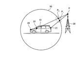
- FIG. 29 and 30 will be used to explain the reason why the conventional image generation apparatus generates a panoramic image with a sense of incongruity.
- FIG. 29 and FIG. 30 are diagrams for explaining problems in the prior art.
- FIG. 29 shows a state in which the vehicle 10 is viewed from the side surface direction
- FIG. 30 shows a state in which the vehicle 10 is viewed from the top surface direction.
- the vehicle 10 is equipped with an image generation device.
- the vehicle 10 has a camera 20 mounted on the front, a camera 21 mounted on the rear, a camera 22 mounted on the left side, and a camera 23 mounted on the right side.
- the image generation device mounted on the vehicle 10 captures a camera image around the vehicle with each of the cameras 20 to 23 and projects the captured camera image on a virtual spherical screen 50.
- the spherical screen 50 is set around the vehicle 10.
- the image generation apparatus acquires from the camera 21 and the camera 22 a camera image obtained by imaging a radio tower located far away as the imaging target 30.
- the image generation apparatus projects an image at the position “P” of the subject 30 captured by the camera 21 onto the position “P 1 ” of the spherical screen 50.
- the image generation device projects the image of the position “P” of the subject 30 captured by the camera 22 onto the position “P 2 ” of the spherical screen 50. That is, the image generation apparatus projects the image at the position “P” of the subject 30 to the position “P 1 ” and the position “P 2 ”. Then, as a result of converting the doubly projected spherical image into a flat image, the image generating device generates a panoramic image that is uncomfortable for the driver.
- the image generation apparatus acquires from the camera 20 and the camera 23 a camera image obtained by shooting a white line on the road surface as the shooting target 30.
- the image generation apparatus projects an image at the position “P” of the subject 30 captured by the camera 20 onto the position “P 1 ” of the spherical screen 50.
- the image generating apparatus projects an image of the position “P” of the subject 30 captured by the camera 23 onto the position “P 2 ” of the spherical screen 50. That is, the image generation apparatus projects the image at the position “P” of the subject 30 to the position “P 1 ” and the position “P 2 ”.
- the image generating device generates a panoramic image that is uncomfortable for the driver.
- a panoramic image having a sense of incongruity is generated from a camera image having parallax. This is because the distance between the cameras cannot be ignored for a subject to be photographed in the vicinity of the camera. For example, even if the radius of the spherical screen 50 that projects the image at the position “P” to be imaged in FIG. 30 is set to infinity, the distance between the position “P 1 ” and the position “P 2 ” on the projection plane is A panoramic image with a sense of incongruity is generated without converging.
- the disclosed technology has been made in view of the above, and provides an image generation device, an image generation program, a synthesis table generation device, and a synthesis table generation program capable of generating a panoramic image with less discomfort for the user. With the goal.
- the technology disclosed in the present application includes, in one aspect, an image receiving unit that receives a camera image captured by a plurality of cameras having a common subject area, and each of the camera images received by the image receiving unit.
- a projection unit that projects an image below a predetermined horizontal line in each camera image onto a bottom surface of an infinite hemisphere having a flat bottom surface, and projects an image above the horizontal line onto a hemispheric surface of the infinite hemisphere.
- a panorama image generation unit that generates a panorama image based on the image projected onto the infinity hemisphere by the projection unit.
- FIG. 1 is a block diagram illustrating the configuration of the image generation apparatus according to the first embodiment.
- FIG. 2 is a diagram for explaining the principle of the image generation apparatus.
- FIG. 3 is a diagram for explaining camera parameters.
- FIG. 4 is a diagram for explaining camera parameters.
- FIG. 5 is a diagram for explaining camera parameters.
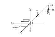
- FIG. 6 is a diagram illustrating the relationship between the camera image and the incident light vector “Vi”.
- FIG. 7 is a diagram illustrating the relationship between the camera image and the incident light vector “Vi”.
- FIG. 8 is a diagram illustrating the relationship between the panoramic image and the incident light vector “Vp (Q)”.
- FIG. 9 is a diagram illustrating the relationship between the panoramic image and the incident light vector “Vp (Q)”.
- FIG. 1 is a block diagram illustrating the configuration of the image generation apparatus according to the first embodiment.
- FIG. 2 is a diagram for explaining the principle of the image generation apparatus.
- FIG. 3 is a diagram for explaining camera parameters.
- FIG. 10 is a diagram illustrating the relationship between the panoramic image and the incident light vector “Vp (Q)”.
- FIG. 11 is a diagram illustrating the relationship between the incident light vector “Vp (Q)” and the stereoscopic screen.
- FIG. 12 is a diagram illustrating the relationship between the incident light vector “Vp (Q)” and the stereoscopic screen.
- FIG. 13 is a diagram illustrating a relationship between a stereoscopic screen and a camera image.
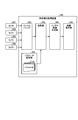
- FIG. 14 is a block diagram illustrating configurations of the vehicle periphery monitoring device and the synthesis table generation device according to the second embodiment.
- FIG. 15 is a diagram illustrating an example of data stored in the synthesis table according to the second embodiment.
- FIG. 16 is a diagram illustrating an example of a camera image according to the second embodiment.
- FIG. 17 is a diagram illustrating an example of a camera image according to the second embodiment.
- FIG. 18 is a diagram illustrating an example of a camera image according to the second embodiment.
- FIG. 19 is a diagram illustrating an example of a camera image according to the second embodiment.
- FIG. 20 is a diagram illustrating an example of a panoramic image displayed by the vehicle periphery monitoring device according to the second embodiment.
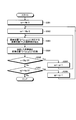
- FIG. 21 is a flowchart illustrating a processing procedure of the synthesis table generation device according to the second embodiment.
- FIG. 22 is a flowchart illustrating a processing procedure of the synthesis table generation apparatus according to the second embodiment.
- FIG. 23 is a flowchart illustrating a processing procedure of the vehicle periphery monitoring apparatus according to the second embodiment.
- FIG. 24 is a block diagram illustrating the configuration of the vehicle periphery monitoring device according to the third embodiment.
- FIG. 25 is a flowchart illustrating a processing procedure of the vehicle periphery monitoring apparatus according to the third embodiment.
- FIG. 26 is a flowchart illustrating a processing procedure of the vehicle periphery monitoring device according to the third embodiment.
- FIG. 27 is a schematic diagram illustrating an example of a panoramic image generation process according to the second embodiment.
- FIG. 28 is a diagram illustrating a hardware configuration of a computer constituting the image generating apparatus according to the second embodiment.
- FIG. 29 is a diagram for explaining a problem in the prior art.
- FIG. 30 is a diagram for explaining a problem in the prior art.
- FIG. 1 is a block diagram illustrating the configuration of the image generation apparatus according to the first embodiment.
- the image generating apparatus 1 according to the first embodiment includes an image receiving unit 2, a projecting unit 3, and a panoramic image generating unit 4.
- the image receiving unit 2 receives camera images taken by a plurality of cameras having a common subject area.
- the projection unit 3 projects the image below the predetermined horizontal line in each camera image received from the image reception unit 2 onto the bottom surface of an infinite hemisphere having a flat bottom surface.
- the image above the predetermined horizontal line is projected onto the hemisphere of the infinite hemisphere.
- the panorama image generation unit 4 generates a panorama image based on the image projected onto the infinite hemisphere by the projection unit 3.
- FIG. 2 is a diagram for explaining the principle of the image generation apparatus.
- the image generation device 1 is mounted on the vehicle 10.
- FIG. 2 shows a state in which the vehicle 10 is viewed from the left side.
- the vehicle 10 has a camera 20 mounted on the front side, a camera 21 mounted on the rear side, and a camera 22 mounted on the left side.
- the vehicle 10 has a camera 23 mounted on the right side as well as the left side.
- the image generation device 1 mounted on the vehicle 10 captures images around the vehicle with the cameras 20 to 23 and projects the captured images onto a virtual stereoscopic screen 40.
- images taken by the cameras 20 to 23 may be expressed as camera images.
- the three-dimensional screen 40 is a point of an infinite hemisphere having a point on the road surface immediately below the center of the vehicle 10 as an origin “O”, a radius “R” being infinite, and a bottom surface on a plane that is the same height as the road surface. It is a projection surface of the shape.
- the reason why the image generation device 1 projects the image above the horizontal line of the camera image onto the hemisphere of the infinity hemisphere is that the effect of parallax is exerted on the far object 30 by projecting onto the hemisphere of the infinity hemisphere. This is because it can be reduced.
- the image generation apparatus 1 captures the position “P 1 ” of the distant object 30 with the camera 21 and the camera 22, and projects the imaged position “P 1 ” on the hemisphere of the infinite hemisphere. To do. In this case, since the distance from the cameras 20 to 23 to the subject 30 is sufficiently larger than the distance between the cameras 20 to 23, the distance between the cameras can be ignored.
- the image generating apparatus 1 has the hemispherical position of the infinite hemisphere for both the position “P 1 ” of the photographing target 30 photographed by the camera 21 and the position “P 1 ” of the photographing target 30 photographed by the camera 22. Project to “C 1 ”.
- images that are above the horizon among camera images often include far-field shooting targets such as the sky and buildings. For this reason, the image generation device 1 probabilistically reduces the influence of parallax by projecting an image above the horizontal line of the camera image onto the hemisphere of the infinity hemisphere.
- the reason why the image generation device 1 projects the image below the horizontal line of the camera image on the bottom surface of the infinity hemisphere is that the image object 30 on the road surface is affected by parallax by projecting the image onto the bottom surface of the infinity hemisphere. It is because it can reduce.
- the image generation apparatus 1 captures the position “P 2 ” on the road surface with the camera 20 and the camera 22, and projects the captured position “P 2 ” on the bottom surface of the infinity hemisphere.
- the position “P 2 ” is the same position “P 2 ” even when projected onto the bottom surface of the infinite hemisphere.
- the image generating apparatus 1 even when projecting the position "P 2" on the road taken by the camera 20, even if the projection position on the road surface captured by the camera 22 to "P 2", the same position "P 2 ”.
- an image below the horizontal line often includes a road surface or an object present on the road surface.
- the image generation device 1 probabilistically reduces the influence of parallax by projecting an image below the horizon among the camera images onto the bottom surface of the infinite hemisphere.
- the image generating apparatus 1 projects each of a plurality of camera images onto the hemisphere of the infinite hemisphere with the image above the horizontal line, and the image below the horizontal line with the image of the infinite hemisphere. Project to the bottom. Then, the image generation device 1 generates a panoramic image from the projected image. For this reason, according to the image generation apparatus 1, it is possible to generate a panoramic image with less discomfort for the user.
- vehicle periphery monitoring device and the synthesis table generation device will be described.
- the vehicle periphery monitoring device generates a panoramic image using the synthesis table generated by the synthesis table generation device.
- the vehicle periphery monitoring device is an example of an image generation device according to the first embodiment.
- generation apparatus use is demonstrated first, and the structure, process, and effect of a vehicle periphery monitoring apparatus and a synthetic
- generation apparatus are demonstrated next.
- FIG. 3 shows the relationship between the camera coordinate system of the cameras 20 to 23 and the optical axis 60.
- the origin “O” is placed at the optical center of the cameras 20 to 23
- the direction opposite to the optical axis 60 is the Zc axis
- the horizontal direction passing through the origin “O” is X c.
- This is a coordinate system in which the vertical direction passing through the origin “O” is the Yc axis.
- FIG. 4 shows a state in which the vehicle 10 is viewed from the top surface direction
- FIG. 5 shows a state in which the vehicle 10 is viewed from the side surface direction.
- the vehicle coordinate system the horizontal direction place the origin "O" on the road surface directly beneath the center of the vehicle 10, the traveling direction of the vehicle 10 and Y w axis, perpendicular to the Y w axis It was a X w axis is a coordinate system with Z w axis perpendicular direction perpendicular to the Y w axis.
- the vehicle coordinate system corresponds to the world coordinate system.
- the vehicle 10 has a camera 20 mounted on the front, a camera 21 mounted on the rear, a camera 22 mounted on the left side, and a camera 23 mounted on the right side.
- the parameters of the cameras 20 to 23 mounted on the vehicle 10 include position parameters (xw, yw, zw) indicating the three-dimensional coordinates of each camera in the vehicle coordinate system. Further, the parameters of the cameras 20 to 23 include angle parameters ( ⁇ , ⁇ , ⁇ ) indicating the inclination of the camera coordinate system of each camera with respect to the vehicle coordinate system.
- Pan angle ⁇ indicates the angle which the optical axis 60 is rotated on the X w Y w plane as the base of the Y w axis.
- the direction of the pan angle theta, the right screw direction of Z w axis is a positive direction.
- the depression angle ⁇ indicates an angle at which the optical axis 60 is inclined in the vertical direction with respect to the horizontal direction.
- the downward direction is the positive direction.
- the rotation angle ⁇ indicates a rotation angle about the optical axis 60 of the Yc axis of each camera.
- the direction of the left screw around the optical axis 60 (the direction of the right screw around the Zc axis) is the positive direction.
- FIG. 6 schematically shows a camera image 70 taken by any of the cameras 20 to 23.
- the camera image coordinate system place the origin “O” in the center of the camera image 70, the horizontal direction passing through the origin "O" and X P axis, a vertical passing through the origin "O” Y
- the coordinate system is the P axis.
- the position “P” of the subject 30 included in the camera image 70 has coordinates (px, py). These coordinates (px, py) indicate the pixel position of “P”. That is, the pixel position “P” is determined for each camera image captured by the camera.
- FIG. 7 schematically shows the incident light vector “Vi” in the camera coordinate system.
- the incident light vector “Vi” is a unit direction vector of a line segment connecting the position “P” of the subject 30 and the optical centers of the cameras 20 to 23. Regarding the direction of the incident light vector Vi, the direction from the position “P” toward the optical center is a positive direction. If the mapping is “T” between the coordinates of the position “P” in the camera image coordinate system and the incident light vector “Vi”, the following equation (1) is established.
- the mapping “T” is a value given to each camera from camera parameters and lens distortion.
- the spherical screen 90 is a virtual sphere in which the center “S” of the sphere is placed at the center of the vehicle in the vehicle coordinate system and the radius is “1”.
- a projection image projected on a stereoscopic screen 40 described later is converted into a planar image by polar coordinate projection.
- 8 to 10 are diagrams showing the relationship between the panoramic image and the incident light vector “Vp (Q)”.
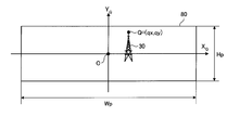
- FIG. 8 schematically shows a panoramic image 80 generated by the vehicle periphery monitoring device. As shown in FIG.
- the panoramic image coordinate system is placed in the center of the panoramic image 80 to the origin "O", the horizontal direction passing through the origin "O” and X Q axis, the vertical direction passing through the origin “O” Y
- the coordinate system is the Q axis.
- Panoramic image 80 has a number of pixels "Wp” in X Q axis, having a number of pixels "Hp” in Y Q axis.
- the position “Q” of the subject 30 included in the panorama image 80 has coordinates (qx, qy). These coordinates (qx, qy) indicate the pixel position of “Q”.
- the position “Q” included in the panoramic image 80 is a position corresponding to the position “P” included in the camera image 70.
- the projection may be converted to a planar image by perspective projection or cylindrical projection. good.
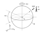
- FIG. 9 schematically shows a spherical screen 90 used in polar coordinate projection.
- Latitudinal spherical screen 90 corresponds to the Y Q axis of the panoramic image 80
- the longitude direction of the spherical screen 90 corresponds to the X Q-axis direction of the panoramic image 80.
- the area included in the horizontal angle of view “Aoh” and the vertical angle of view “Aov” of the spherical screen 90 covers the number of pixels “Wp ⁇ Hp” of the panoramic image 80 shown in FIG.
- the angular resolution per pixel of the panoramic image 80 is “Aoh / Wp” degrees and “Aov / Hp” degrees.
- the incident light vector “Vp (Q)” is a unit direction vector of a line segment connecting the position “Q” of the subject 30 and the center “S” of the spherical screen 90. Regarding the direction of the incident light vector “Vp (Q)”, the direction from the position “Q” to the center “S” is defined as a positive direction.
- the center “S” of the spherical screen 90 is not limited to the center of the vehicle, and may be set at an arbitrary position. For example, the center “S” of the spherical screen 90 may be set to the position of the line of sight when the driver gets on the vehicle.
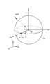
- FIG. 10 shows a process of deriving an equation for calculating the incident light vector “Vp (Q)”.
- FIG. 10 shows the same spherical screen 90 as in FIG. 9 in the vehicle coordinate system.
- the straight line parallel to the Xw axis from the center “S” of the spherical screen 90 is “X”
- the straight line parallel to the Yw axis from the center “S” is “Y”
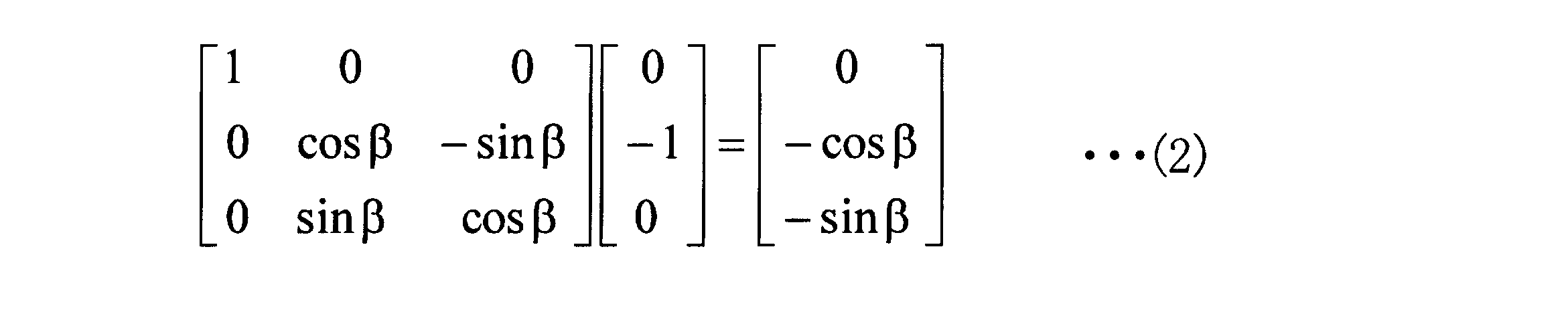
- the incident light vector “Vp (Q)” is obtained by rotating the unit vector (0, ⁇ 1, 0) from the straight line “Y” to the center “S” by “ ⁇ ” degrees in the vertical direction and “ ⁇ ” in the horizontal direction.
- the incident light vector “Vp (Q)” is expressed by the following equation (4).
- the angles “ ⁇ ” and “ ⁇ ” in Expression (4) can be expressed by parameters of the panoramic image coordinate system using the angular resolution per pixel of the panoramic image. That is, the angle “ ⁇ ” is expressed by the following equation (5), and the angle “ ⁇ ” is expressed by the following equation (6).
- 11 and 12 are diagrams showing the relationship between the incident light vector “Vp (Q)” and the stereoscopic screen.
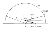
- the three-dimensional screen 40 is an infinite hemisphere having an origin “O” in the vehicle coordinate system as the center of the bottom surface and a radius “R” being infinite.
- a position “C” is defined as an intersection point between a straight line obtained by extending the incident light vector “Vp (Q)” obtained by Expression (4) in the reverse direction and the stereoscopic screen 40.
- FIG. 11 is a diagram for explaining a process of deriving an expression for calculating the position “C”.
- FIG. 11 shows the three-dimensional screen 40 in the vehicle coordinate system.
- the linear equation for each component of the equation (7) is expressed by the following equations (8) to (10).
- FIG. 12 shows a state in which the spherical screen 90 and the stereoscopic screen 40 are viewed from the side.
- the center “S” has coordinates (0, 0, sz).
- the position “C” exists on the bottom surface of the stereoscopic screen 40.
- the z component is negative “Vpz ⁇ 0”
- the position “C” exists on the hemispherical surface of the stereoscopic screen 40.
- Vp (Q) (Vpx, Vpy, Vpz)”. That is, the constant “k” in Expression (20) is represented by the following Expression (21) derived from Expression (19) when “Vpz> 0”, and when “Vpz ⁇ 0”, It is represented by the following formula (22) derived from the formula (18).
- the constant “a” in Expression (22) is represented by the following Expression (23) derived from Expression (13).
- the constant “b” in Expression (22) is represented by the following Expression (24) derived from Expression (14).
- the constant “c” in Expression (22) is represented by the following Expression (25) derived from Expression (15).
- FIG. 13 is a diagram illustrating a relationship between a stereoscopic screen and a camera image.
- FIG. 13 shows a state in which the stereoscopic screen 40 and the vehicle 10 are viewed from the side surface direction.
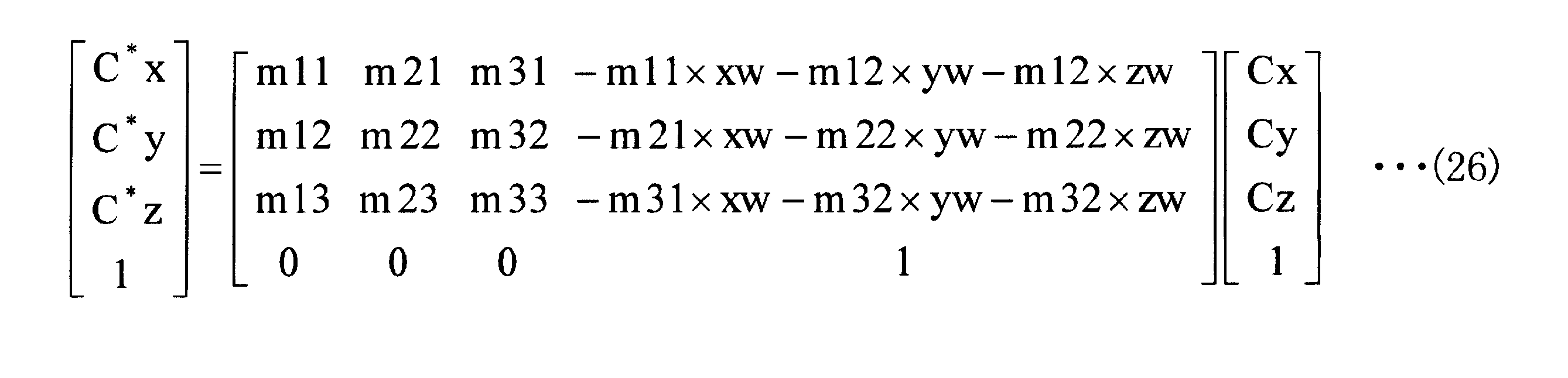
- the position “C * ” translates the position “C” by the camera position parameters (xw, yw, zw), and rotates the position “C” by the camera angle parameters ( ⁇ , ⁇ , ⁇ ).
- the position “C * ” is represented by the following formula (26). Note that “m11” to “m33” in the equation (26) are expressed by the following equations (27) to (35).
- an incident light vector “Vi” in the camera coordinate system is calculated from the position “C * ” obtained by Expression (26).
- the incident light vector “Vi” is expressed by the following equation (36) using the function “Unit ()”.
- the function “Unit ()” is a function that converts an arbitrary vector into a unit vector. Further, since the incident light vector “Vi” is in the opposite direction to the vector of the position “C * ”, the sign is changed.
- the incident light vector “Vi” obtained by the equation (36) is converted into the position “P” in the camera image coordinate system by using the equation (1).
- the synthesis table generation apparatus 100 uses the above-described equations (1) to (36), so that the pixel position “Q” of the panoramic image 80 generated from the plurality of camera images 70 and the pixel position of the camera image 70 are displayed. The correspondence with “P” is calculated.
- FIG. 14 is a block diagram illustrating configurations of the vehicle periphery monitoring device and the synthesis table generation device according to the second embodiment.
- the synthesis table generation apparatus 100 according to the second embodiment includes a parameter storage unit 110, a projection unit 120, and a synthesis table generation unit 130.
- the vehicle periphery monitoring device 200 according to the second embodiment includes a frame buffer 210, a panoramic image generation unit 220, and an image display unit 230. Further, the synthesis table generation device 100 and the vehicle periphery monitoring device 200 are mounted on the vehicle 10.
- the vehicle periphery monitoring device 200 is connected to the cameras 20 to 23 and the synthesis table generating device 100, respectively.
- Example 2 demonstrates the case where the synthetic
- the synthesis table generation device 100 may be installed outside the vehicle 10, and the synthesis table generated by the synthesis table generation device 100 may be sent to the vehicle periphery monitoring device 200.
- the parameter storage unit 110 stores the parameters 110a of the cameras 20 to 23.
- the parameter 110a includes a position parameter (xw, yw, zw) and an angle parameter ( ⁇ , ⁇ , ⁇ ).
- the parameter 110 a is input by a person who installed the cameras 20 to 23 on the vehicle 10.
- the parameter 110a is corrected using the camera image 70 taken by the cameras 20 to 23 installed in the vehicle 10.
- the projection unit 120 projects pixel position information included in camera images captured by a plurality of cameras having a common subject area as follows. That is, the projection unit 120 projects the position information of the pixels below the horizontal line in each camera image onto the bottom surface of the infinite hemisphere, and the position information of the pixels above the horizontal line in each camera image Project to the hemisphere hemisphere.
- the projection unit 120 corresponds to the pixel position “Q” of the panoramic image 80 generated from the plurality of camera images 70 by using the parameters of the cameras 20 to 23 and the above equations (1) to (36).
- the pixel position “P” of the camera image 70 to be calculated is calculated. Then, when the calculated pixel position “P” is a coordinate in the camera image, the projecting unit 120 extracts the pixel position “P” as a pixel position corresponding to the pixel position “Q”.
- the constant “k” in Expression (20) is calculated by Expression (21) when “Vpz> 0”, and is calculated by Expression (22) when “Vpz ⁇ 0”.
- the constants “a” to “c” in the equation (22) are calculated by the equations (23) to (25). For “sz”, for example, “1.5 m” is used as the height of the driver's eyes.
- radius “R” for example, “10 km” is used as a value sufficiently larger than the distance between the cameras. “Sz” and “R” are not limited to these values, but may be set to arbitrary values by a person using the synthesis table generating apparatus 100.
- the reason why the radius “R” is set to “10 km” instead of infinite is that a panoramic image without a sense of incongruity can be generated by this setting.
- the radius “R” is set to “10 km”
- the distance between the cameras is “2 m”
- the influence of parallax is exerted on a subject to be photographed that is “114 m” or more away from the projection center “S”. Fits within 1 degree.
- the effect of parallax is within 2 degrees for a subject to be photographed that is “57 m” or more away from the projection center “S”.
- the effect of parallax is within 5 degrees for a subject to be photographed that is “22 m” or more away from the projection center “S”.
- “m11” to “m33” in Expression (26) are calculated by Expressions (27) to (35).
- the valid flag is a flag indicating whether or not the pixel position “P” corresponding to the pixel position “Q” of the panoramic image 80 is included in the coordinates of the camera image 70 captured by the cameras 20 to 23. . Then, the projection unit 120 extracts the pixel position “P” with the valid flag set to ON as the pixel position corresponding to the pixel position “Q”.
- the synthesis table generation unit 130 Based on the result of projection onto the infinite hemisphere by the projection unit 120, the synthesis table generation unit 130 associates the positional information of each pixel included in the panoramic image 80 with the positional information of each pixel included in the camera image 70. Is generated. For example, the synthesis table generation unit 130 associates the pixel position “Q” of the panoramic image 80 with the pixel position “P” for which the valid flag is set to ON, and generates the synthesis table 130a. Then, the synthesis table generation unit 130 sends the generated synthesis table 130a to the panoramic image generation unit 220.
- the synthesis table 130 a generated by the synthesis table generation unit 130 stores a correspondence relationship between the pixel position “Q” of the panoramic image 80 and the pixel position “P” of the camera image 70.
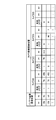
- FIG. 15 is a diagram illustrating an example of data stored in the synthesis table according to the second embodiment. As shown in FIG. 15, the synthesis table 130a is associated with a combination of “qx” and “qy”, with “valid flag”, “px”, and “py” for each of the cameras 20 to 23 that capture the camera image 70. ”Is memorized. Here, the combination of “qx” and “qy” indicates the pixel position “Q” on the panoramic image.
- the combination of “px” and “py” indicates the pixel position “P” on the camera image captured by each camera.
- the “valid flag” indicates that the association between the pixel position “Q” and the pixel position “P” is valid.
- the combination table 130a stores a combination of the valid flag “0”, px “null”, and py “null” for the camera 22 in association with the combination of qx “156” and qy “63”.
- the valid flag “1” indicates that the valid flag is set to ON, and indicates that the pixel position “P” corresponding to the pixel position “Q” is included in the coordinates of the camera image 70.
- “Null” indicates that no data is included in the corresponding part. That is, the combination of the valid flag “0”, px “null”, and py “null” indicates that the pixel position “P” corresponding to the pixel position “Q” is not included in the coordinates of the camera image 70.
- the composition table 130a also associates the “valid flag” for each camera 20 to 23 that captures the camera image 70 in association with the combination of “qx” and “qy” for the other pixel positions of the panoramic image 80. ”,“ Px ”, and“ py ”are stored.
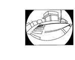
- 16 to 19 are diagrams illustrating examples of camera images according to the second embodiment. 16 to 19 show examples of camera images taken by the cameras 20 to 23, respectively. Then, the cameras 20 to 23 send the generated camera image data to the frame buffer 210.
- the second embodiment as shown in FIG. 4 and FIG. 5, the case where four cameras are installed in the vehicle 10 will be described. However, the present embodiment is not limited to this, and is common. What is necessary is just to install the several camera which has a to-be-photographed area in the vehicle 10. FIG. For example, more cameras may be installed behind the vehicle 10.
- the frame buffer 210 stores the data of the camera image 70 received from the cameras 20 to 23.
- the frame buffer 210 stores the data of the camera image 70 for each of the cameras 20-23.
- the panoramic image generation unit 220 generates a panoramic image 80 from a plurality of camera images 70.
- the panorama image generation unit 220 acquires the data of the camera image 70 from the frame buffer 210.
- the panorama image generation unit 220 refers to the synthesis table 130a received from the synthesis table generation unit 130, and for each pixel position “Q” of the panorama image 80, the pixel value of the pixel position “P” for which the valid flag is set to ON. Are extracted from the data of the camera image 70.
- the pixel value is, for example, an RGB (Red, Green, Blue) value.
- the panoramic image generation unit 220 blends the pixel values of the extracted pixel position “P”. As blending, for example, an average value of each pixel value may be calculated, or an average value with a weight based on the pixel position may be calculated.
- the panoramic image generation unit 220 generates the panoramic image 80 by recording the blended pixel value at the pixel position “Q”. For example, when a memory corresponding to an image of “1200 ⁇ 400 pixels” is included, the panoramic image generation unit 220 records the blended pixel value on the memory at the pixel position corresponding to the pixel position “Q”. A panoramic image 80 is generated. Then, the panorama image generation unit 220 sends the generated panorama image 80 to the image display unit 230.
- the image display unit 230 displays the panoramic image 80 received from the panoramic image generation unit 220.
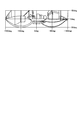
- FIG. 20 is a diagram illustrating an example of a panoramic image displayed by the vehicle periphery monitoring device according to the second embodiment. As shown in FIG. 20, the image display unit 230 displays, for example, a panoramic image having a horizontal field angle “Aoh” of ⁇ 180 to +180 degrees and a vertical field angle “Aov” of ⁇ 30 to +30 degrees.
- FIG. 21 is a flowchart illustrating a processing procedure of the synthesis table generation device according to the second embodiment.
- the process of the synthesis table generating apparatus 100 is performed prior to the process of the vehicle periphery monitoring apparatus 200.
- the process of the synthesis table generation apparatus 100 is started when the synthesis table generation apparatus 100 receives camera parameters.
- the process of the synthesis table generation device 100 is started at a time designated by a person using the synthesis table generation device 100.
- the projection unit 120 sets “Hp / 2” to the coordinates “qy” (step S101).
- the projection unit 120 sets “ ⁇ Wp / 2” to the coordinates “qx” (step S102).
- FIG. 22 is a flowchart illustrating a processing procedure of the synthesis table generation apparatus according to the second embodiment.
- the projection unit 120 sets the valid flag of the pixel position “P” to on (step S205).
- the projection unit 120 extracts the pixel position “P” with the valid flag set to ON as a pixel position corresponding to the pixel position “Q” (step S206).
- the projection unit 120 sets the valid flag of the pixel position “P” to off (step S207).
- the synthesis table generation unit 130 generates a synthesis table 130a (step S109). For example, the synthesis table generation unit 130 records the valid flag and the pixel position “P” in the synthesis table 130 a in association with the pixel position “Q” of the panoramic image 80.
- the synthesis table generation unit 130 determines whether or not the coordinate “qx” is a value smaller than “Wp / 2” (step S110).
- the synthesis table generation unit 130 sets “qx + 1” to the coordinate “qx” and performs the process of Step S103. (Step S111). That is, the synthesis table generation unit 130 sets the coordinates on the right of one pixel of the coordinates “qx” in the panoramic image coordinate system as the next processing target, and executes the processing from step S103.
- the synthesis table generating unit 130 determines that the coordinate “qy” is larger than “ ⁇ Hp / 2”. It is determined whether or not there is (step S112). When it is determined that the coordinate “qy” is a value larger than “ ⁇ Hp / 2” (Yes at Step S112), the synthesis table generating unit 130 sets “qy ⁇ 1” to the coordinate “qy”, and the step The process returns to S102 (step S113). That is, the synthesis table generation unit 130 sets the coordinates one pixel below the coordinate “qy” in the panoramic image coordinate system as the next processing target, and executes the processing from step S102.
- the synthesis table generating unit 130 ends the process. Note that the processes in steps S102 to S113 are repeated until the process is performed on all the pixel positions “Q” of the panoramic image 80.
- step S105 to step S108 which is the extraction processing of the pixel position “P” using the parameters of the camera n (n is 20, 21, 22, or 23), may be executed in an arbitrary order. Further, for example, the processes in steps S105 to S108 may be executed in parallel.
- the above processing procedure is executed in order from the upper left coordinate of the panoramic image coordinate system
- the present embodiment is not limited to this.
- the above processing procedure may be executed from any coordinate of the panoramic image coordinate system.
- the above processing procedure may be executed simultaneously in four regions after dividing the panoramic image coordinate system into four regions.
- FIG. 23 is a flowchart illustrating a processing procedure of the vehicle periphery monitoring apparatus according to the second embodiment.
- the processing of the vehicle periphery monitoring device 200 may be started at an arbitrary timing as long as the synthesis table 130a is present.
- the process of the vehicle periphery monitoring device 200 is started with the activation of the vehicle 10 and the camera. Also, for example, it is started when a person using the vehicle periphery monitoring device 200 designates.
- the panorama image generation unit 220 sets “Hp / 2” to the coordinates “qy” (step S301).
- the panorama image generation unit 220 sets “ ⁇ Wp / 2” to the coordinates “qx” (step S302).
- the panorama image generation unit 220 refers to the synthesis table 130 a and extracts the pixel value of the pixel position “P” for which the valid flag is set to ON from the data of the camera image 70.
- the panoramic image generation unit 220 records the extracted pixel value at the pixel position “Q” (step S304).
- the panoramic image generation unit 220 blends the pixel values of the extracted pixel position “P” and records them at the pixel position “Q”. To do.
- the panorama image generation unit 220 determines whether or not the coordinate “qx” is a value smaller than “Wp / 2” (step S305).
- the panoramic image generation unit 220 sets “qx + 1” to the coordinate “qx” (Step S306).
- the process returns to step S303. That is, the panorama image generation unit 220 sets the coordinates one pixel to the right of the coordinates “qx” in the panorama image coordinate system as the next processing target, and executes the processing from step S103.
- step S305 when it is determined that the coordinate “qx” is not a value smaller than “Wp / 2” (No in step S305), the panoramic image generation unit 220 has a value greater than “ ⁇ Hp / 2” as the coordinate “qy”. It is determined whether or not there is (step S307). When it is determined that the coordinate “qy” is larger than “ ⁇ Hp / 2” (Yes at Step S307), the panoramic image generation unit 220 sets “qy ⁇ 1” to the coordinate “qy” (Step S307). S308), the process returns to step S302. That is, the panorama image generation unit 220 sets the coordinates one pixel below the coordinate “qy” in the panorama image coordinate system as the next processing target, and executes the processing from step S102.
- the panoramic image generation unit 220 ends the process. It should be noted that the processing from step S302 to step S308 is repeated until the processing is performed on all the pixel positions “Q” of the panoramic image 80.
- the panorama image generation unit 220 generates one panorama image 80 by the above processing, and sends the generated panorama image 80 to the image display unit 230.
- the image display unit 230 updates and displays the panorama image 80 every time the panorama image 80 is received from the panorama image generation unit 220.
- the synthesis table generating apparatus 100 uses the parameters of the cameras 20 to 23 to indicate the correspondence between the pixel position “Q” of the panoramic image 80 and the pixel position “P” of the camera image 70. 130a is generated.
- the vehicle periphery monitoring apparatus 200 refers to the synthesis table 130a generated by the synthesis table generation apparatus 100 and extracts the pixel value of the pixel position “P” corresponding to the pixel position “Q” of the panorama image, thereby obtaining a panoramic image. Is generated. For this reason, according to the second embodiment, it is possible to generate a panoramic image with less discomfort for the user.
- the pixel position “P” is associated. That is, the synthesis table generating apparatus 100 projects the pixel position below the horizontal line passing through the center “S” onto the bottom surface of the stereoscopic screen 40. Since an image below the horizon often includes objects existing on the road surface, according to the second embodiment, the influence of the parallax is reduced probabilistically for the image below the horizon among the camera images. A panoramic image can be generated.
- the synthesis table generating apparatus 100 generates a synthesis table 130a indicating the correspondence between the pixel position “Q” of the panoramic image 80 and the pixel position “P” of the camera image 70 prior to the generation of the panoramic image.
- the vehicle periphery monitoring apparatus 200 produces
- a panoramic image can be generated with a small amount of processing.
- the vehicle periphery monitoring apparatus 200 generates a panoramic image with a small amount of processing by using the synthesis table 130a generated by the synthesis table generation apparatus 100. Therefore, according to the second embodiment, a panoramic image can be generated as a moving image from moving images taken by the cameras 20 to 23.
- the cameras 20 to 23 correspond to CMOS (Complementary Metal Oxide Semiconductor Image Sensor) cameras and CCD (Charge Coupled Device Image Sensor) cameras.
- the camera image data generated by the cameras 20 to 23 may be a still image or a moving image.
- the parameter storage unit 110 and the frame buffer 210 correspond to, for example, a semiconductor memory device such as a RAM (Random Access Memory), a ROM (Read Only Memory), and a flash memory (Flash Memory), a hard disk, and an optical disk.
- a semiconductor memory device such as a RAM (Random Access Memory), a ROM (Read Only Memory), and a flash memory (Flash Memory), a hard disk, and an optical disk.
- the projection unit 120, the synthesis table generation unit 130, and the panorama image generation unit 220 are realized by an integrated circuit or an electronic circuit.
- the integrated circuit for example, ASIC (Application Specific Integrated Circuit), FPGA (Field Programmable Gate Array), or the like can be applied.
- CPU Central Processing Unit
- MPU Micro Processing Unit
- the image display unit 230 corresponds to, for example, a monitor or a liquid crystal display.
- vehicle periphery monitoring apparatus An example of a vehicle periphery monitoring apparatus according to the third embodiment will be described.
- the vehicle periphery monitoring apparatus generates a panoramic image without using a synthesis table will be described.
- the vehicle periphery monitoring device is an example of an image generation device according to the first embodiment. Since the mathematical formula used by the vehicle periphery monitoring apparatus according to the third embodiment is the same as the mathematical formula according to the second embodiment, description thereof is omitted.
- FIG. 24 is a block diagram illustrating the configuration of the vehicle periphery monitoring device according to the third embodiment.
- the vehicle periphery monitoring apparatus 300 according to the third embodiment includes a parameter storage unit 310, a frame buffer 320, a projection unit 330, a panoramic image generation unit 340, and an image display unit 350.
- the vehicle periphery monitoring device 300 is mounted on the vehicle 10.
- the vehicle periphery monitoring device 300 is connected to the cameras 301 to 304.
- the cameras 301 to 304, parameter storage unit 310, frame buffer 320, and image display unit 350 shown in FIG. 24 are added to the cameras 20 to 23, parameter storage unit 110, frame buffer 210, and image display unit 230 shown in FIG. Since the same processing is performed for each of them, description thereof will be omitted.
- the projection unit 330 projects an image below the horizontal line in each camera image among the camera images received by the frame buffer 320 onto the bottom surface of the infinite hemisphere, and an image above the horizontal line in each camera image. Projects onto the hemisphere of an infinite hemisphere.
- the projection unit 330 corresponds to the pixel position “Q” of the panoramic image 80 generated from the plurality of camera images 70 by using the parameters of the cameras 301 to 304 and the above equations (1) to (36).
- the pixel position “P” of the camera image 70 to be calculated is calculated. Then, when the calculated pixel position “P” is a coordinate in the camera image, the projection unit 330 extracts the pixel value of the pixel position “P” as a pixel value corresponding to the pixel position “Q”.
- the constant “k” in Expression (20) is calculated by Expression (21) when “Vpz> 0”, and is calculated by Expression (22) when “Vpz ⁇ 0”.
- the constants “a” to “c” in the equation (22) are calculated by the equations (23) to (25). For “sz”, for example, “1.5 m” is used as the height of the driver's eyes.
- radius “R” for example, “10 km” is used as a value sufficiently larger than the distance between the cameras. “Sz” and “R” are not limited to these values, and a person who uses the synthesis table generation apparatus 100 may set them to arbitrary values.
- “m11” to “m33” in Expression (26) are calculated by Expressions (27) to (35).
- the projection unit 330 determines whether or not the calculated pixel position “P” is included in the coordinates of the camera image 70. When the projection unit 330 determines that the calculated pixel position “P” is included in the coordinates of the camera image 70, the projection unit 330 extracts the pixel value of the pixel position “P”.
- the panoramic image generation unit 340 generates a panoramic image 80 based on the image projected onto the infinite hemisphere by the projection unit 330. For example, the panorama image generation unit 340 records the pixel value of the pixel position “P” extracted by the projection unit 330 in the corresponding pixel position “Q”. Here, for the pixel position “Q” where each camera image 70 overlaps, the panorama image generation unit 340 blends the pixel values of the extracted pixel position “P”. The panorama image generation unit 340 generates the panorama image 80 by recording the extracted pixel value at the pixel position “Q”.
- the panoramic image generation unit 220 records the blended pixel value on the memory at the pixel position corresponding to the pixel position “Q”. A panoramic image 80 is generated. Then, the panorama image generation unit 340 sends the generated panorama image 80 to the image display unit 350.
- FIG. 25 is a flowchart illustrating a processing procedure of the vehicle periphery monitoring apparatus according to the third embodiment.
- the processing of the vehicle periphery monitoring device 300 may be started at an arbitrary timing.
- the process of the vehicle periphery monitoring device 200 is started with the activation of the vehicle 10 and the camera. Also, for example, it is started when a person using the vehicle periphery monitoring device 200 designates.
- the projection unit 330 sets “Hp / 2” to the coordinates “qy” (step S401).
- the projection unit 330 sets “ ⁇ Wp / 2” to the coordinates “qx” (step S402).
- FIG. 26 is a flowchart illustrating a processing procedure of the vehicle periphery monitoring device according to the third embodiment.
- the projection unit 330 sets the pixel value of the pixel position “P” to the pixel value corresponding to the pixel position “Q”. (Step S505).
- the projection unit 330 ends the process.
- the panorama image generation unit 340 records the extracted pixel value at the pixel position “Q” (step S409). At this time, for the pixel position “Q” where each camera image 70 overlaps, the panorama image generation unit 340 blends the pixel values of the extracted pixel position “P” and records them at the pixel position “Q”. To do.
- the panorama image generation unit 340 determines whether or not the coordinate “qx” is a value smaller than “Wp / 2” (step S410).
- the panoramic image generation unit 340 sets “qx + 1” to the coordinate “qx” (Step S411).
- the process returns to step S403. That is, the panorama image generation unit 340 sets the coordinates one pixel to the right of the coordinates “qx” in the panorama image coordinate system as the next processing target, and executes the processing from step S403.
- step S410 when it is determined that the coordinate “qx” is not a value smaller than “Wp / 2” (No at Step S410), the panoramic image generation unit 340 has a value greater than “ ⁇ Hp / 2” as the coordinate “qy”. It is determined whether or not there is (step S412). When it is determined that the coordinate “qy” is larger than “ ⁇ Hp / 2” (Yes at Step S412), the panoramic image generation unit 340 sets “qy ⁇ 1” to the coordinate “qy” (Step S412). S413), the process returns to step S402. That is, the panorama image generation unit 340 sets the coordinates one pixel below the coordinate “qy” in the panorama image coordinate system as the next processing target, and executes the processing from step S402.
- the panoramic image generation unit 340 ends the process. It should be noted that the processing from step S402 to step S413 is repeated until the processing is performed on all the pixel positions “Q” of the panoramic image 80.
- the panorama image generation unit 340 generates one panorama image 80 by the above processing, and sends the generated panorama image 80 to the image display unit 350.
- the image display unit 350 updates and displays the panorama image 80 every time the panorama image 80 is received from the panorama image generation unit 340.
- steps S405 to S408 which is the extraction processing of the pixel value of the pixel position “P” from each camera image taken by the camera n (n is 20, 21, 22, or 23), is performed in an arbitrary order. May be executed. Further, for example, the processes in steps S405 to S408 may be executed in parallel.
- the above processing procedure is executed in order from the upper left coordinate of the panoramic image coordinate system
- the present embodiment is not limited to this.
- the above processing procedure may be executed from any coordinate of the panoramic image coordinate system.
- the above processing procedure may be executed simultaneously in four areas after dividing the panoramic image coordinate system into four areas.
- the vehicle periphery monitoring apparatus 300 uses the parameters of the cameras 301 to 304 to extract the pixel value of the pixel position “P” corresponding to the pixel position “Q” of the panoramic image 80. Then, the vehicle periphery monitoring apparatus 300 generates a panoramic image from the extracted pixel value of the pixel position “P”. For this reason, according to the third embodiment, it is possible to generate a panoramic image with less discomfort for the user without generating a synthesis table.
- the image generation apparatus is mounted on a vehicle, but the present embodiment is not limited to this.
- the image generation device may be mounted on a ship, a monitoring device, a robot, or the like.
- the image generation apparatus disclosed in the present application can generate a panoramic image with less discomfort in an apparatus equipped with the image generation apparatus.
- the present embodiment is not limited to this.
- the constant “k” in Expression (20) is expressed by Expression (19) when “Vpz> 0”, and is expressed by Expression (18) when “Vpz ⁇ 0”.
- the constants “a” to “c” in Expression (18) are expressed by Expressions (13) to (15).
- the synthesis table generating apparatus 100 projects the pixel position above the horizontal line passing through the center “S” onto the hemispherical surface of the stereoscopic screen 40 and is below the horizontal line passing through the center “S”. It has been described that the pixel position is projected onto the bottom surface of the stereoscopic screen 40 (see FIG. 12). However, the present embodiment is not limited to this. For example, when “Vpz ⁇ N”, the synthesis table generation apparatus 100 projects the pixel position onto the hemispherical surface of the stereoscopic screen 40, and when “Vpz> N”, the synthesis table generating apparatus 100 sets the pixel position to the bottom surface of the stereoscopic screen 40.
- N is an arbitrary number, see equations (20) to (22)). That is, a person using the synthesis table generating apparatus 100 may set the horizontal line at an arbitrary position by setting an arbitrary number for “N”. As a result, the image generating apparatus disclosed in the present application can generate a panoramic image using a horizontal line set by the user.
- the synthesis table generating apparatus 100 has been described as associating the pixel position “P” of the camera image with all the pixel positions “Q” of the panoramic image.
- the present embodiment is limited to this. It is not a thing.
- the synthesizing table generating apparatus 100 generates the synthesizing table 130a in which the correspondence relationship between the pixel position “Q” and the pixel position “P” is sparsely defined, and generates an undefined pixel position “Q” when generating a panoramic image. "May be obtained by linear interpolation.
- the synthesis table generating apparatus 100 can generate the synthesis table 130a with a reduced data amount.
- the panorama image generation unit 220 may generate the panorama image so that the camera image captured by a predetermined camera is positioned at the center of the panorama image according to the situation of the vehicle 10 equipped with a plurality of cameras. good.
- FIG. 27 is a schematic diagram illustrating an example of a panoramic image generation process according to the second embodiment.
- the panoramic image generation unit 220 includes a generation memory and a display memory.
- the panorama image generation unit 220 generates a generation panorama image 81 by recording pixel values on a generation memory.
- an area 400 is an area in which pixel values of a camera image taken by the front camera 20 are recorded.
- An area 401 is an area in which pixel values of camera images taken by the rear camera 21 are recorded.
- An area 402 is an area in which pixel values of a camera image taken by the left camera 22 are recorded.
- An area 403 is an area in which pixel values of a camera image captured by the right camera 23 are recorded. That is, the panorama image generation unit 220 generates the panorama image 81 for generation so that the camera image 70 captured by the front camera 20 is positioned at the center of the panorama image 81.
- the panorama image generation unit 220 receives information indicating the state of the vehicle 10 and re-records the pixel values of the panorama image 81 on the display memory, thereby generating a display panorama image 82. For example, when the information indicating that the operation lever of the vehicle 10 has been shifted from the drive range to the reverse range is received from the vehicle 10, the panoramic image generation unit 220 determines to change the center position of the panoramic image to the region 401. .
- the panorama image generation unit 220 divides the panorama image 81 at a position with a horizontal angle of view of 180 degrees from the center of the region 401, that is, a dotted line position shown in FIG.
- the norama image generation unit 220 generates a panorama image 82 for display by fusing the divided panorama images so that the region 401 is located at the center.
- the panoramic image 82 generated in this way is displayed on the image display unit 230. That is, when the operation lever is shifted from the drive range to the reverse range, the panorama image 82 centered on the camera image taken by the rear camera 21 is displayed on the image display unit 230.
- the panorama image generation unit 220 can generate a panorama image with less discomfort according to the vehicle situation.
- the panorama image generation unit 220 generates the panorama image 82 using the generation memory and the display memory.
- the present embodiment is not limited to this.
- the panorama image generation unit 220 performs the following process. That is, when the panoramic image generation unit 220 records the pixel value on the display memory, the panoramic image generation unit 220 sets the position where the pixel value is recorded so that the region corresponding to the situation of the vehicle 10 is located at the center of the panoramic image 82. After the change, the pixel value is recorded on the display memory.
- the situation of the vehicle 10 includes not only the situation of the operation lever but also the situation of the steering wheel, the situation of the pedal, the situation of surrounding objects, and the like.
- each component of each illustrated apparatus is functionally conceptual, and does not necessarily need to be physically configured as illustrated.
- the specific form of distribution / integration of each device is not limited to that shown in the figure, and all or a part thereof may be functionally or physically distributed or arbitrarily distributed in arbitrary units according to various loads or usage conditions. Can be integrated and configured.
- the image display unit 230 may be connected as an external device of the vehicle periphery monitoring device 200.
- FIG. 28 is a schematic diagram illustrating an example of a computer that executes an image generation program according to the second embodiment. Note that a computer that executes an image generation program having the same function as that of the third embodiment is the same as that shown in FIG.
- the computer 3000 in the second embodiment includes an input device 3001, a monitor 3002, a camera 3003, a CPU 3010, a ROM 3011, an HDD (Hard Disk Drive) 3012, and a RAM (Random Access Memory) 3013.
- the computer 3000 is configured by connecting input devices 3001 to RAM 3013 via a bus 3009 or the like.
- the ROM 3011 stores a control program that exhibits the same functions as those of the projection unit 120, the synthesis table generation unit 130, and the panoramic image generation unit 220 described in the second embodiment. That is, as shown in FIG. 28, the ROM 3011 stores in advance a projection program 3011a, a synthesis table generation program 3011b, and a panoramic image generation program 3011c. Note that these programs 3011a to 3011c may be integrated or separated as appropriate, similar to the constituent elements of the synthesis table generation device 100 and the vehicle periphery monitoring device 200 shown in FIG.
- the CPU 3010 reads out these programs 3011a to 3011c from the ROM 3011 and executes them.
- each of the processes 3010a to 3010c functions as a projection process 3010a, a synthesis table generation process 3010b, and a panoramic image generation process 3010c.
- Each process 3010a to 3010c corresponds to the projection unit 120, the synthesis table generation unit 130, and the panoramic image generation unit 220 shown in FIG.
- each processing unit virtually realized on the CPU 3010 does not always need to operate all the processing units on the CPU 3010, and only a processing unit necessary for processing may be virtually realized.
- the HDD 3012 is provided with a parameter table 3012a.
- the parameter table 3012a corresponds to the parameter storage unit 110 illustrated in FIG.
- the CPU 3010 reads the parameter table 3012a and stores it in the RAM 3013.
- the CPU 3010 executes the image generation program using the parameter data 3013a stored in the RAM 3013. Note that the data stored in the RAM 3013 does not always need to be stored in the RAM 3013, and only data necessary for processing may be stored in the RAM 3013.
- the image generation program described in this embodiment can be distributed via a network such as the Internet.
- the image generation program can also be executed by being recorded on a computer-readable recording medium such as a hard disk, a flexible disk (FD), a CD-ROM, an MO, and a DVD, and being read from the recording medium by the computer.
- a computer-readable recording medium such as a hard disk, a flexible disk (FD), a CD-ROM, an MO, and a DVD
Landscapes
- Engineering & Computer Science (AREA)
- Multimedia (AREA)
- Signal Processing (AREA)
- Physics & Mathematics (AREA)
- General Physics & Mathematics (AREA)
- Theoretical Computer Science (AREA)
- Closed-Circuit Television Systems (AREA)
- Studio Devices (AREA)
- Image Processing (AREA)
Abstract
画像生成装置は、画像受付部と、投影部と、パノラマ画像生成部とを有する。画像受付部は、共通の被写領域を有する複数のカメラでそれぞれ撮影されたカメラ画像を受け付ける。投影部は、画像受付部によって受け付けた各カメラ画像のうち、各カメラ画像内の所定の水平線より下にある画像(Vpz>0)は、平面の底面を有する無限遠半球の底面(C(Vpz>0))に投影し、各カメラ画像内の所定の水平線より上にある画像(Vpz≦0)は、無限遠半球の半球面(C(Vpz≦0))に投影する。パノラマ画像生成部は、投影部によって無限遠半球に投影された画像に基づいて、パノラマ画像を生成する。
Description
本発明は、画像生成装置、画像生成プログラム、合成テーブル生成装置および合成テーブル生成プログラムに関する。
従来、複数のカメラで撮影された画像からパノラマ画像を生成する画像生成装置がある。例えば、画像生成装置は、撮影範囲が全方位をカバーするように複数のカメラが設けられた360度カメラから周囲の画像を取得する。画像生成装置は、取得した複数のカメラ画像を、360度カメラを中心とした仮想的な球面スクリーンに投影する。各々のカメラ画像が球面スクリーン上で重なり合う部分については、画像生成装置は、重なり部分の画素値をブレンドし、球面画像を生成する。そして、画像生成装置は、球面スクリーンに投影された球面画像を、球の中心からの透視法投影、球の中心を中心軸が通る円筒投影または中心を一致させた極座標投影により平面画像に変換し、360度のパノラマ画像を生成する。
また、パノラマ画像の生成における視差の影響を軽減する技術がある。視差とは、複数のカメラの設置位置の違いによって、撮影対象が見える角度が異なることである。この技術は、「カメラから撮影対象までの距離がカメラ間の距離に比べて十分に大きい場合には、カメラ間の距離を無視できること」を利用して、視差の影響を軽減する。例えば、カメラから撮影対象までの距離が十分に離れている場合には、カメラ画像を投影する仮想的な球面スクリーンの半径を無限大に設定することで、視差の影響を軽減したパノラマ画像を生成する。
S. Ikeda、他2名、「Generating a Panorama Movie Using an Omnidirectional Multi-camera System」、Institute of Electronics, Intormation and Communication Engineers、2002年
ところで、上述した従来の画像生成装置では、各々のカメラ画像に視差がない場合には、各々のカメラ画像の重なり部分が一致したパノラマ画像が生成される。このため、従来の画像生成装置は、視差を無視できるほど近接してカメラを設置するか、視差を無視できるほど遠方の撮影対象に限って撮影する必要があった。
ここで、設置位置が異なる複数のカメラで撮影されたカメラ画像からパノラマ画像を生成し、利用者に提供すれば有用であろう。例えば、車両の前後左右に搭載された車載カメラからカメラ画像を取得し、取得したカメラ画像からパノラマ画像を生成して運転者に提供できれば、レーンチェンジ時やバック時などに有用であると考えられる。しかしながら、従来の画像生成装置は、視差のある複数のカメラ画像からパノラマ画像を生成すると、各々のカメラ画像の重なり部分を球面スクリーンに二重に投影する結果、利用者にとって違和感のあるパノラマ画像を生成してしまうという問題があった。
図29および図30を用いて、従来の画像生成装置が違和感のあるパノラマ画像を生成してしまう理由について説明する。図29および図30は、従来技術における問題点を説明するための図である。図29は、車両10を側面方向から見た状態を示し、図30は、車両10を上面方向から見た状態を示す。図29および図30に示す例では、車両10は、画像生成装置を搭載する。車両10は、前方にカメラ20を搭載し、後方にカメラ21を搭載し、左側にカメラ22を搭載し、右側にカメラ23を搭載する。車両10に搭載された画像生成装置は、各カメラ20~23で車両周囲のカメラ画像を撮影し、撮影したカメラ画像を仮想的な球面スクリーン50に投影する。なお、球面スクリーン50は、車両10を中心として設定される。
図29に示す例では、撮影対象30が遠方にある場合を説明する。画像生成装置は、遠方にある電波塔を撮影対象30として撮影したカメラ画像をカメラ21およびカメラ22から取得する。画像生成装置は、カメラ21で撮影した撮影対象30の位置「P」の画像を球面スクリーン50の位置「P1」に投影する。一方、画像生成装置は、カメラ22で撮影した撮影対象30の位置「P」の画像を球面スクリーン50の位置「P2」に投影する。つまり、画像生成装置は、撮影対象30の位置「P」の画像を位置「P1」および位置「P2」に二重に投影する。そして、画像生成装置は、二重に投影された球面画像を平面画像に変換する結果、運転者にとって違和感のあるパノラマ画像を生成してしまう。
図30に示す例では、撮影対象30が近傍にある場合を説明する。画像生成装置は、路面上にある白線を撮影対象30として撮影したカメラ画像をカメラ20およびカメラ23から取得する。画像生成装置は、カメラ20で撮影した撮影対象30の位置「P」の画像を球面スクリーン50の位置「P1」に投影する。一方、画像生成装置は、カメラ23で撮影した撮影対象30の位置「P」の画像を球面スクリーン50の位置「P2」に投影する。つまり、画像生成装置は、撮影対象30の位置「P」の画像を位置「P1」および位置「P2」に二重に投影する。そして、画像生成装置は、二重に投影された球面画像を平面画像に変換する結果、運転者にとって違和感のあるパノラマ画像を生成してしまう。
また、従来の画像生成装置は、視差の影響を軽減する技術を用いても、視差のあるカメラ画像から違和感のあるパノラマ画像を生成してしまう。なぜなら、カメラの近傍にある撮影対象については、カメラ間の距離を無視できないからである。例えば、図30において撮影対象の位置「P」の画像を投影した球面スクリーン50の半径を無限大に設定しても、投影面上の位置「P1」と位置「P2」との間隔は収束せず、違和感のあるパノラマ画像を生成してしまう。
開示の技術は、上記に鑑みてなされたものであって、利用者にとって違和感の少ないパノラマ画像を生成可能である画像生成装置、画像生成プログラム、合成テーブル生成装置および合成テーブル生成プログラムを提供することを目的とする。
本願の開示する技術は、一つの態様において、共通の被写領域を有する複数のカメラでそれぞれ撮影されたカメラ画像を受け付ける画像受付部と、前記画像受付部によって受け付けた各カメラ画像のうち、該各カメラ画像内の所定の水平線より下にある画像は、平面の底面を有する無限遠半球の底面に投影し、前記水平線より上にある画像は、前記無限遠半球の半球面に投影する投影部と、前記投影部によって前記無限遠半球に投影された画像に基づいて、パノラマ画像を生成するパノラマ画像生成部とを有する。
本願の開示する技術の一つの態様によれば、利用者にとって違和感の少ないパノラマ画像を生成可能であるという効果を奏する。
以下に、図面を参照しつつ、本願の開示する画像生成装置、画像生成プログラム、合成テーブル生成装置および合成テーブル生成プログラムの一実施形態について詳細に説明する。なお、本願の開示する画像生成装置、画像生成プログラム、合成テーブル生成装置および合成テーブル生成プログラムの一実施形態として以下に説明する実施例により、本願の開示する技術が限定されるものではない。各実施例は、処理内容を矛盾させない範囲で適宜組み合わせることが可能である。
図1は、実施例1に係る画像生成装置の構成を示すブロック図である。図1に示すように、実施例1に係る画像生成装置1は、画像受付部2と、投影部3と、パノラマ画像生成部4とを有する。
画像受付部2は、共通の被写領域を有する複数のカメラでそれぞれ撮影されたカメラ画像を受け付ける。投影部3は、画像受付部2によって受け付けた各カメラ画像のうち、各カメラ画像内の所定の水平線より下にある画像は、平面の底面を有する無限遠半球の底面に投影し、各カメラ画像内の所定の水平線より上にある画像は、無限遠半球の半球面に投影する。パノラマ画像生成部4は、投影部3によって無限遠半球に投影された画像に基づいて、パノラマ画像を生成する。
図2を用いて、画像生成装置1の原理について説明する。図2は、画像生成装置の原理を説明するための図である。図2に示す例では、画像生成装置1は、車両10に搭載されるものとする。図2には、車両10を左側面から見た状態を示す。車両10は、前方にカメラ20を搭載し、後方にカメラ21を搭載し、左側にカメラ22を搭載する。なお、車両10は、左側と同様に右側にもカメラ23を搭載する。車両10に搭載された画像生成装置1は、各カメラ20~23で車両周囲の画像を撮影し、撮影した画像を仮想的な立体スクリーン40に投影する。以降、各カメラ20~23により撮影された画像をカメラ画像と表現する場合がある。立体スクリーン40は、車両10の中心直下に位置する路面上の点を原点「O」とし、半径「R」を無限大とするとともに、路面と同じ高さの平面に底面を有する無限遠半球の形状の投影面である。
画像生成装置1が、カメラ画像のうち水平線より上にある画像を無限遠半球の半球面に投影する理由は、無限遠半球の半球面に投影することで遠方の撮影対象30について視差の影響を軽減できるからである。図2に示す例では、画像生成装置1は、カメラ21およびカメラ22で遠方の撮影対象30の位置「P1」を撮影し、撮影した位置「P1」を無限遠半球の半球面に投影する。この場合、カメラ20~23から撮影対象30までの距離がカメラ20~23間の距離に比べて十分に離れているので、カメラ間の距離を無視できる。つまり、画像生成装置1は、カメラ21で撮影した撮影対象30の位置「P1」についても、カメラ22で撮影した撮影対象30の位置「P1」についても、無限遠半球の半球面の位置「C1」に投影する。また、カメラ画像のうち水平線より上にある画像については、空や建築物など遠方の撮影対象が含まれる場合が多い。このため、画像生成装置1は、カメラ画像のうち水平線より上にある画像を無限遠半球の半球面に投影することで、確率的に視差の影響を軽減する。
また、画像生成装置1が、カメラ画像のうち水平線より下にある画像を無限遠半球の底面に投影する理由は、無限遠半球の底面に投影することで路面上の撮影対象30について視差の影響を軽減できるからである。図2に示す例では、画像生成装置1は、カメラ20およびカメラ22で路面上の位置「P2」を撮影し、撮影した位置「P2」を無限遠半球の底面に投影する。この場合、車両10の路面と無限遠半球の底面は一致しているので、位置「P2」は、無限遠半球の底面に投影されても同じ位置「P2」である。つまり、画像生成装置1は、カメラ20で撮影した路面上の位置「P2」を投影しても、カメラ22で撮影した路面上の位置「P2」を投影しても、同じ位置「P2」である。また、カメラ画像のうち水平線より下にある画像については、路面や路面上に存在する物体が含まれる場合が多い。このため、画像生成装置1は、カメラ画像のうち水平線より下にある画像を無限遠半球の底面に投影することで、確率的に視差の影響を軽減する。
このように、実施例1に係る画像生成装置1は、複数のカメラ画像それぞれを、水平線より上にある画像は無限遠半球の半球面に投影し、水平線より下にある画像は無限遠半球の底面に投影する。そして、画像生成装置1は、投影された画像からパノラマ画像を生成する。このようなことから、画像生成装置1によれば、利用者にとって違和感の少ないパノラマ画像を生成可能である。
実施例2に係る車両周辺監視装置および合成テーブル生成装置の一例について説明する。実施例2では、車両周辺監視装置が合成テーブル生成装置により生成された合成テーブルを用いてパノラマ画像を生成する場合を説明する。なお、車両周辺監視装置は、実施例1の画像生成装置の一例である。以下では、まず、車両周辺監視装置および合成テーブル生成装置が用いる数式の導出について説明し、次に、車両周辺監視装置および合成テーブル生成装置の構成、処理および効果について説明する。
[実施例2に係る数式の導出]
まず、カメラのパラメータについて説明する。図3~図5は、カメラのパラメータを説明するための図である。図3は、カメラ20~23のカメラ座標系と光軸60との関係を示す。図3に示すように、カメラ座標系は、カメラ20~23の光学中心に原点「O」を置き、光軸60の反対方向をZc軸とし、原点「O」を通る水平方向をXc軸とし、原点「O」を通る垂直方向をYc軸とする座標系である。
まず、カメラのパラメータについて説明する。図3~図5は、カメラのパラメータを説明するための図である。図3は、カメラ20~23のカメラ座標系と光軸60との関係を示す。図3に示すように、カメラ座標系は、カメラ20~23の光学中心に原点「O」を置き、光軸60の反対方向をZc軸とし、原点「O」を通る水平方向をXc軸とし、原点「O」を通る垂直方向をYc軸とする座標系である。
図4は、車両10を上面方向から見た状態を示し、図5は、車両10を側面方向から見た状態を示す。図4および図5に示すように、車両座標系は、車両10の中心直下の路面上に原点「O」を置き、車両10の進行方向をYw軸とし、Yw軸と直行する水平方向をXw軸とし、Yw軸と直行する垂直方向をZw軸とする座標系である。なお、車両座標系は、ワールド座標系に対応する。
車両10は、前方にカメラ20を搭載し、後方にカメラ21を搭載し、左側にカメラ22を搭載し、右側にカメラ23を搭載する。車両10に搭載されるカメラ20~23のパラメータには、車両座標系における各カメラの3次元座標を示す位置パラメータ(xw、yw、zw)が含まれる。また、カメラ20~23のパラメータには、車両座標系に対する各カメラのカメラ座標系の傾きを示す角度パラメータ(θ、ψ、φ)が含まれる。パン角θは、光軸60がYw軸を基点としてXwYw平面上で回転する角度を示す。パン角θの方向については、Zw軸回りの右ネジ方向を正の方向とする。例えば、図4では、カメラ20の光軸60とYw軸とが成す角度をθFとする。俯角ψは、光軸60が水平方向を基点として垂直方向に傾く角度を示す。俯角ψの方向については、下方向を正の方向とする。例えば、図5では、カメラ20の光軸60が水平方向から下方に傾く角度をψFとする。回転角φは、各カメラのYc軸の光軸60を軸とする回転角度を示す。回転角φの方向は光軸60回りに左ネジの方向(Zc軸回りに右ネジの方向)を正の方向とする。
次に、カメラ画像と入射光ベクトル「Vi」との関係について説明する。図6および図7は、カメラ画像と入射光ベクトル「Vi」との関係を示す図である。図6は、カメラ20~23のいずれかにより撮影されたカメラ画像70を模式的に示す。図6に示すように、カメラ画像座標系は、カメラ画像70の中心に原点「O」を置き、原点「O」を通る水平方向をXP軸とし、原点「O」を通る垂直方向をYP軸とする座標系である。カメラ画像座標系において、カメラ画像70に含まれる撮影対象30の位置「P」は、座標(px、py)を有する。この座標(px、py)が、「P」の画素位置を示す。つまり、画素位置「P」は、カメラにより撮影されたカメラ画像ごとに決定される。
図7は、カメラ座標系における入射光ベクトル「Vi」を模式的に示す。入射光ベクトル「Vi」は、撮影対象30の位置「P」とカメラ20~23の光学中心とを結んだ線分の単位方向ベクトルである。入射光ベクトルViの方向については、位置「P」から光学中心へ向かう方向を正の方向とする。カメラ画像座標系における位置「P」の座標と入射光ベクトル「Vi」との間には、写像を「T」とすると、下記の式(1)が成立する。写像「T」は、カメラのパラメータとレンズの歪みから、各カメラごとに与えられる値である。

次に、パノラマ画像80と球面スクリーン90との関係について説明する。ここで、球面スクリーン90は、車両座標系における車両の中心に球の中心「S」を置き、半径を「1」とした仮想的な球である。実施例2では、後述の立体スクリーン40に投影された投影画像を極座標投影により平面画像に変換する場合を説明する。図8~図10は、パノラマ画像と入射光ベクトル「Vp(Q)」との関係を示す図である。図8は、車両周辺監視装置により生成されるパノラマ画像80を模式的に示す。図8に示すように、パノラマ画像座標系は、パノラマ画像80の中心に原点「O」を置き、原点「O」を通る水平方向をXQ軸とし、原点「O」を通る垂直方向をYQ軸とする座標系である。パノラマ画像80は、XQ軸方向に「Wp」の画素数を有し、YQ軸方向に「Hp」の画素数を有する。パノラマ画像座標系において、パノラマ画像80に含まれる撮影対象30の位置「Q」は、座標(qx、qy)を有する。この座標(qx、qy)が、「Q」の画素位置を示す。なお、パノラマ画像80に含まれる位置「Q」は、カメラ画像70に含まれる位置「P」に相当する位置である。なお、実施例2では、極座標投影により平面画像に変換する場合を説明するが、本実施例はこれに限定されるものではなく、例えば、透視法投影や円筒投影によって平面画像に変換しても良い。
図9は、極座標投影で用いられる球面スクリーン90を模式的に示す。球面スクリーン90の緯度方向はパノラマ画像80のYQ軸方向に対応し、球面スクリーン90の経度方向はパノラマ画像80のXQ軸方向に対応する。球面スクリーン90の水平画角「Aoh」度および垂直画角「Aov」度に含まれる領域が、図8に示したパノラマ画像80の「Wp×Hp」の画素数をカバーする。このとき、パノラマ画像80の1画素当たりの角度分解能は、「Aoh/Wp」度および「Aov/Hp」度となる。入射光ベクトル「Vp(Q)」は、撮影対象30の位置「Q」と球面スクリーン90の中心「S」とを結んだ線分の単位方向ベクトルである。入射光ベクトル「Vp(Q)」の方向については、位置「Q」から中心「S」へ向かう方向を正の方向とする。なお、球面スクリーン90の中心「S」は、車両の中心に限定されるものではなく、任意の位置に設定しても良い。例えば、球面スクリーン90の中心「S」は、運転者が車両に乗車した際の目線の位置に設定しても良い。
図10は、入射光ベクトル「Vp(Q)」を算出する式の導出過程を示す。図10は、車両座標系に図9と同じ球面スクリーン90を示す。図10では、球面スクリーン90の中心「S」からXw軸と平行な直線を「X」とし、中心「S」からYw軸と平行な直線を「Y」とし、中心「S」からZw軸と平行な直線を「Z」とする。入射光ベクトル「Vp(Q)」は、直線「Y」から中心「S」へ向かう単位ベクトル(0、-1、0)を、垂直方向に「β」度回転させ、水平方向に「α」度回転させた方向ベクトルである。つまり、単位ベクトル(0、-1、0)を垂直方向に「β」度回転させた方向ベクトルは、下記の式(2)で算出される。そして、式(2)により算出された方向ベクトルを水平方向に「α」度回転させた方向ベクトルは、下記の式(3)で算出される。

したがって、入射光ベクトル「Vp(Q)」は、下記の式(4)で表される。なお、式(4)の角度「α」および「β」は、パノラマ画像の1画素当たりの角度分解能を用いると、パノラマ画像座標系のパラメータで表すことができる。つまり、角度「α」は下記の式(5)で表され、角度「β」は下記の式(6)で表される。



次に、入射光ベクトル「Vp(Q)」と立体スクリーン40との関係について説明する。図11および図12は、入射光ベクトル「Vp(Q)」と立体スクリーンとの関係を示す図である。立体スクリーン40は、車両座標系における原点「O」を底面の中心とし、半径「R」を無限大とした無限遠半球である。式(4)により求められる入射光ベクトル「Vp(Q)」を逆方向に伸ばした直線と、立体スクリーン40との交点を位置「C」とする。
図11は、位置「C」を算出する式の導出過程を説明するための図を示す。図11は、車両座標系における立体スクリーン40を示す。一般的に、位置「S=(Sx、Sy、Sz)」を通る傾き「V=(Vx、Vy、Vz)」の直線の方程式は、定数「k」を用いると、下記の式(7)で示される。また、式(7)の各成分ごとの直線の方程式は、下記の式(8)~(10)で示される。




位置「C」が立体スクリーン40の半球面上に存在する場合には、下記の式(11)に示す球面の方程式と、式(8)~(10)との連立方程式から、下記の式(12)が算出される。


続いて、下記の式(13)~(15)を用いて置き換えると、式(12)は、下記の式(16)に変形される。




そして、式(16)に二次方程式の解の公式を用いると、定数「k」は、下記の式(17)で表される。位置「C」は方向ベクトル「V」の方向に存在するので、定数「k」は、下記の式(18)で表される。


また、位置「C」が立体スクリーン40の底面上に存在する場合には、式(10)において「z=0」であるので、定数「k」は、下記の式(19)で表される。

図12は、球面スクリーン90と立体スクリーン40とを側面方向から見た状態を示す。図12を車両座標系に当てはめると、車両10の中心直下に位置する路面上の点が原点「O」であり、原点「O」を通る水平方向の直線は「Zw=0平面」である。中心「S」は、座標(0、0、sz)を有する。入射光ベクトル「Vp(Q)=(Vpx、Vpy、Vpz)」のz成分が正「Vpz>0」の場合には、位置「C」は、立体スクリーン40の底面に存在する。また、z成分が負の「Vpz≦0」の場合には、位置「C」は、立体スクリーン40の半球面に存在する。
図11において算出された式(8)~(10)に、中心「S=(0、0、sz)」と入射光ベクトル「Vp(Q)=(Vpx、Vpy、Vpz)」とを代入すると、位置「C=(Cx、Cy、Cz)」は、下記の式(20)で表される。なお、式(4)により求められる入射光ベクトル「Vp(Q)」は、図11に示した単位方向ベクトル「V」を逆向きにしたベクトルであるので、各成分の符号を変えて代入する。また、式(20)の定数「k」は、図11において算出された式(13)~(15)および式(19)に、中心「S=(0、0、sz)」と入射光ベクトル「Vp(Q)=(Vpx、Vpy、Vpz)」とを代入することで表される。つまり、式(20)の定数「k」は、「Vpz>0」の場合には、式(19)より導かれる下記の式(21)で表され、「Vpz≦0」の場合には、式(18)より導かれる下記の式(22)で表される。式(22)の定数「a」は、式(13)より導かれる下記の式(23)で表される。式(22)の定数「b」は、式(14)より導かれる下記の式(24)で表される。式(22)の定数「c」は、式(15)より導かれる下記の式(25)で表される。






次に、立体スクリーンとカメラ画像との関係について説明する。図13は、立体スクリーンとカメラ画像との関係を示す図である。図13は、立体スクリーン40と車両10とを側面方向から見た状態を示す。図13では、式(20)により求められる車両座標系における位置「C=(Cx、Cy、Cz)」を、カメラ座標系における位置「C*=(C*x、C*y、C*z)」に変換する。位置「C*」は、位置「C」をカメラの位置パラメータ(xw、yw、zw)の分だけ平行移動させ、位置「C」をカメラの角度パラメータ(θ、ψ、φ)の分だけ回転させた位置に相当する。すなわち、位置「C*」は、下記の式(26)で表される。なお、式(26)の「m11」~「m33」は、下記の式(27)~(35)で表される。








続いて、式(26)により求められる位置「C*」から、カメラ座標系における入射光ベクトル「Vi」を算出する。入射光ベクトル「Vi」は、関数「Unit( )」を用いて、下記の式(36)で表される。なお、関数「Unit( )」は、任意のベクトルを単位ベクトルに変換する関数である。また、入射光ベクトル「Vi」は、位置「C*」のベクトルとは逆向きであるので、符号を変えて表される。

式(36)により求められる入射光ベクトル「Vi」は、上記の式(1)を用いることで、カメラ画像座標系における位置「P」に変換される。すなわち、合成テーブル生成装置100は、上述の式(1)~(36)を用いることで、複数のカメラ画像70から生成されるパノラマ画像80の画素位置「Q」と、カメラ画像70の画素位置「P」との対応関係を算出する。
[実施例2の構成]
次に、車両周辺監視装置200および合成テーブル生成装置100の構成について説明する。図14は、実施例2に係る車両周辺監視装置および合成テーブル生成装置の構成を示すブロック図である。図14に示すように、実施例2に係る合成テーブル生成装置100は、パラメータ記憶部110と、投影部120と、合成テーブル生成部130とを有する。また、実施例2に係る車両周辺監視装置200は、フレームバッファ210と、パノラマ画像生成部220と、画像表示部230とを有する。また、合成テーブル生成装置100および車両周辺監視装置200は、車両10に搭載される。また、車両周辺監視装置200は、カメラ20~23と合成テーブル生成装置100とにそれぞれ接続される。なお、実施例2では、合成テーブル生成装置100および車両周辺監視装置200が車両10に搭載される場合を説明するが、本実施例はこれに限定されるものではない。例えば、合成テーブル生成装置100を車両10の外部に設置して、合成テーブル生成装置100で生成される合成テーブルを車両周辺監視装置200に送るようにしても良い。
次に、車両周辺監視装置200および合成テーブル生成装置100の構成について説明する。図14は、実施例2に係る車両周辺監視装置および合成テーブル生成装置の構成を示すブロック図である。図14に示すように、実施例2に係る合成テーブル生成装置100は、パラメータ記憶部110と、投影部120と、合成テーブル生成部130とを有する。また、実施例2に係る車両周辺監視装置200は、フレームバッファ210と、パノラマ画像生成部220と、画像表示部230とを有する。また、合成テーブル生成装置100および車両周辺監視装置200は、車両10に搭載される。また、車両周辺監視装置200は、カメラ20~23と合成テーブル生成装置100とにそれぞれ接続される。なお、実施例2では、合成テーブル生成装置100および車両周辺監視装置200が車両10に搭載される場合を説明するが、本実施例はこれに限定されるものではない。例えば、合成テーブル生成装置100を車両10の外部に設置して、合成テーブル生成装置100で生成される合成テーブルを車両周辺監視装置200に送るようにしても良い。
パラメータ記憶部110は、カメラ20~23のパラメータ110aを記憶する。例えば、パラメータ110aは、位置パラメータ(xw、yw、zw)および角度パラメータ(θ、ψ、φ)を含む。また、例えば、パラメータ110aは、カメラ20~23を車両10に設置した者によって入力される。また、例えば、パラメータ110aは、車両10に設置されたカメラ20~23で撮影されたカメラ画像70を用いて補正される。
投影部120は、共通の被写領域を有する複数のカメラでそれぞれ撮影されるカメラ画像に含まれる画素の位置情報を次のように投影する。すなわち、投影部120は、各カメラ画像内の水平線より下にある画素の位置情報は、無限遠半球の底面に投影し、各カメラ画像内の水平線より上にある画素の位置情報は、無限遠半球の半球面に投影する。例えば、投影部120は、カメラ20~23のパラメータと上述の式(1)~(36)とを用いることで、複数のカメラ画像70から生成されるパノラマ画像80の画素位置「Q」に対応するカメラ画像70の画素位置「P」を算出する。そして、投影部120は、算出した画素位置「P」がカメラ画像内の座標である場合に、画素位置「P」を画素位置「Q」に対応する画素位置として抽出する。
例えば、投影部120は、上述の式(4)を用いて、パノラマ画像80の画素位置「Q=(qx、qy)」に対応する入射光ベクトル「Vp(Q)」を算出する。なお、式(4)の角度「α」および「β」は、式(5)~(6)で算出される。
続いて、投影部120は、算出した入射光ベクトル「Vp(Q)」および位置「S=(0、0、sz)」を上述の式(20)に代入し、車両座標系における位置「C=(Cx、Cy、Cz)」を算出する。なお、式(20)の定数「k」は、「Vpz>0」の場合には、式(21)で算出され、「Vpz≦0」の場合には、式(22)で算出される。また、式(22)の定数「a」~「c」は、式(23)~(25)で算出される。また、「sz」には、例えば、運転者の目線の高さとして「1.5m」を用いる。また、半径「R」には、例えば、カメラ間の距離に比べて十分に大きい値として「10km」を用いる。「sz」および「R」については、これらの値に限るものではなく、合成テーブル生成装置100を利用する者が任意の値に設定して良い。
ここで、半径「R」を無限大ではなく「10km」に設定した理由は、この設定によって違和感の無いパノラマ画像を生成できるからである。例えば、半径「R」を「10km」に設定すると、カメラ間の距離が「2m」である場合には、投影の中心「S」から「114m」以上離れた撮影対象については、視差の影響が1度以内に収まる。また、同様に、投影の中心「S」から「57m」以上離れた撮影対象については、視差の影響が2度以内に収まる。また、同様に、投影の中心「S」から「22m」以上離れた撮影対象については、視差の影響が5度以内に収まる。
続いて、投影部120は、算出した位置「C=(Cx、Cy、Cz)」およびカメラ20~23のパラメータを上述の式(26)に代入し、車両座標系における位置「C」をカメラ座標系における位置「C*=(C*x、C*y、C*z)」に変換する。なお、式(26)の「m11」~「m33」は、式(27)~(35)で算出される。
続いて、投影部120は、変換した位置「C*=(C*x、C*y、C*z)」を上述の式(36)に代入し、入射光ベクトル「Vi」を算出する。投影部120は、算出した入射光ベクトル「Vi」を上述の式(1)に代入し、画素位置「P=(px、py)」を算出する。
続いて、投影部120は、算出した画素位置「P」がカメラ画像70の座標に含まれるか否かを判定する。例えば、「400×400ピクセル」のカメラ画像70を用いる場合には、投影部120は、算出した画素位置「P=(px、py)」が座標「(-200~+200、-200~+200)」に含まれるか否かを判定する。投影部120は、算出した画素位置「P」がカメラ画像70の座標に含まれると判定すると、画素位置「P」の有効フラグをオンに設定する。ここで、有効フラグは、パノラマ画像80の画素位置「Q」に対応する画素位置「P」が、カメラ20~23で撮影されるカメラ画像70の座標に含まれるか否かを示すフラグである。そして、投影部120は、有効フラグをオンに設定された画素位置「P」を画素位置「Q」に対応する画素位置として抽出する。
合成テーブル生成部130は、投影部120によって無限遠半球に投影された結果に基づいて、パノラマ画像80に含まれる各画素の位置情報とカメラ画像70に含まれる各画素の位置情報との対応関係を示す合成テーブル130aを生成する。例えば、合成テーブル生成部130は、パノラマ画像80の画素位置「Q」と、有効フラグがオンに設定された画素位置「P」とを対応付けて、合成テーブル130aを生成する。そして、合成テーブル生成部130は、生成した合成テーブル130aをパノラマ画像生成部220に送る。
合成テーブル生成部130により生成される合成テーブル130aは、パノラマ画像80の画素位置「Q」とカメラ画像70の画素位置「P」との対応関係を記憶する。図15は、実施例2に係る合成テーブルにより記憶されたデータの一例を示す図である。図15に示すように、合成テーブル130aは、「qx」と「qy」との組み合わせに対応付けて、カメラ画像70を撮影するカメラ20~23ごとに「有効フラグ」と「px」と「py」との組み合わせを記憶する。ここで、「qx」と「qy」との組み合わせは、パノラマ画像上の画素位置「Q」を示す。また、「px」と「py」との組み合わせは、各カメラで撮影したカメラ画像上の画素位置「P」を示す。また、「有効フラグ」は、画素位置「Q」と画素位置「P」との対応付けが有効であることを示す。例えば、合成テーブル130aは、qx「156」とqy「63」との組み合わせに対応付けて、カメラ20について、有効フラグ「1」とpx「78」とpy「456」との組み合わせを記憶する。つまり、合成テーブル130aは、パノラマ画像80の画素位置「Q=(156、63)」に、カメラ20で撮影されるカメラ画像70の画素位置「P=(78、456)」が対応することを記憶する。
また、合成テーブル130aは、qx「156」とqy「63」との組み合わせに対応付けて、カメラ21について、有効フラグ「1」とpx「79」とpy「312」との組み合わせを記憶する。つまり、合成テーブル130aは、パノラマ画像80の画素位置「Q=(156、63)」に、カメラ21で撮影されるカメラ画像70の画素位置「P=(79、312)」が対応することを記憶する。また、合成テーブル130aは、qx「156」とqy「63」との組み合わせに対応付けて、カメラ22について、有効フラグ「0」とpx「null」とpy「null」との組み合わせを記憶する。つまり、合成テーブル130aは、パノラマ画像80の画素位置「Q=(156、63)」に、カメラ22で撮影されるカメラ画像70の画素位置が対応しないことを記憶する。また、合成テーブル130aは、qx「156」とqy「63」との組み合わせに対応付けて、カメラ23について、有効フラグ「0」とpx「null」とpy「null」との組み合わせを記憶する。つまり、合成テーブル130aは、パノラマ画像80の画素位置「Q=(156、63)」に、カメラ23で撮影されるカメラ画像70の画素位置が対応しないことを記憶する。なお、有効フラグ「1」は、有効フラグがオンに設定されたことを示し、画素位置「Q」に対応する画素位置「P」がカメラ画像70の座標に含まれること示す。また、「null」は、該当箇所にデータを含まないことを示す。つまり、有効フラグ「0」とpx「null」とpy「null」との組み合わせは、画素位置「Q」に対応する画素位置「P」がカメラ画像70の座標に含まれないこと示す。また、合成テーブル130aは、パノラマ画像80の他の画素位置についても同様に、「qx」と「qy」との組み合わせに対応付けて、カメラ画像70を撮影するカメラ20~23ごとに「有効フラグ」と「px」と「py」との組み合わせを記憶する。
図14の説明に戻る。カメラ20~23は、周辺環境を撮影してカメラ画像70のデータを生成する。図16~19は、実施例2に係るカメラ画像の一例を示す図である。図16~19は、カメラ20~23で撮影されたカメラ画像の一例をそれぞれ示す。そして、カメラ20~23は、生成したカメラ画像のデータをフレームバッファ210に送る。なお、実施例2では、図4および図5で示したように、4台のカメラが車両10に設置された場合を説明するが、本実施例はこれに限定されるものではなく、共通の被写領域を有する複数のカメラが車両10に設置されれば良い。例えば、車両10の後方に、より多くのカメラを設置しても良い。
フレームバッファ210は、カメラ20~23から受け付けたカメラ画像70のデータを格納する。フレームバッファ210は、カメラ20~23ごとにカメラ画像70のデータを格納する。
パノラマ画像生成部220は、複数のカメラ画像70からパノラマ画像80を生成する。例えば、パノラマ画像生成部220は、フレームバッファ210からカメラ画像70のデータを取得する。パノラマ画像生成部220は、合成テーブル生成部130から受け付けた合成テーブル130aを参照し、パノラマ画像80の画素位置「Q」ごとに、有効フラグがオンに設定された画素位置「P」の画素値をカメラ画像70のデータから抽出する。画素値とは、例えば、RGB(Red、Green、Blue)値である。各々のカメラ画像70が重なり合う部分の画素位置「Q」については、パノラマ画像生成部220は、抽出した画素位置「P」の画素値をブレンドする。ブレンドとしては、例えば、各画素値の平均値を算出しても、画素位置に基づく加重を付けた平均値を算出しても良い。
続いて、パノラマ画像生成部220は、ブレンドした画素値を画素位置「Q」に記録することで、パノラマ画像80を生成する。例えば、「1200×400ピクセル」の画像に対応するメモリを有する場合には、パノラマ画像生成部220は、画素位置「Q」に該当する画素位置のメモリ上にブレンドした画素値を記録することで、パノラマ画像80を生成する。そして、パノラマ画像生成部220は、生成したパノラマ画像80を画像表示部230に送る。
画像表示部230は、パノラマ画像生成部220から受け付けたパノラマ画像80を表示する。図20は、実施例2に係る車両周辺監視装置により表示されるパノラマ画像の一例を示す図である。図20に示すように、画像表示部230は、例えば、水平画角「Aoh」が-180~+180度、垂直画角「Aov」が-30~+30度のパノラマ画像を表示する。
[実施例2による処理手順]
図21を用いて、合成テーブル生成装置100の処理手順について説明する。図21は、実施例2に係る合成テーブル生成装置の処理手順を示すフローチャートである。合成テーブル生成装置100の処理は、車両周辺監視装置200の処理に先立って行われる。例えば、合成テーブル生成装置100の処理は、合成テーブル生成装置100がカメラのパラメータを受け付けた時点で開始される。また、例えば、合成テーブル生成装置100の処理は、合成テーブル生成装置100を利用する者が指定した時点で開始される。
図21を用いて、合成テーブル生成装置100の処理手順について説明する。図21は、実施例2に係る合成テーブル生成装置の処理手順を示すフローチャートである。合成テーブル生成装置100の処理は、車両周辺監視装置200の処理に先立って行われる。例えば、合成テーブル生成装置100の処理は、合成テーブル生成装置100がカメラのパラメータを受け付けた時点で開始される。また、例えば、合成テーブル生成装置100の処理は、合成テーブル生成装置100を利用する者が指定した時点で開始される。
図21に示すように、投影部120は、座標「qy」に「Hp/2」を設定する(ステップS101)。座標「qy=Hp/2」は、図8に示したパノラマ画像座標系の上端の座標を示す。投影部120は、座標「qx」に「-Wp/2」を設定する(ステップS102)。座標「qx=-Wp/2」は、図8に示したパノラマ画像座標系の左端の座標を示す。
投影部120は、式(4)を用いて、設定された画素位置「Q=(qx、qy)」に対応する入射光ベクトル「Vp(Q)」を算出する(ステップS103)。続いて、投影部120は、式(20)を用いて、算出した入射光ベクトル「Vp(Q)」から位置「C=(Cx、Cy、Cz)」を算出する(ステップS104)。そして、投影部120は、カメラn(nは20、21、22または23)のパラメータを用いた画素位置「P=(px、py)」の抽出処理を行う(ステップS105~ステップS108)。
ここで、図22を用いて、カメラn(nは20、21、22または23)のパラメータを用いた画素位置「P=(px、py)」の抽出処理について説明する。図22は、実施例2に係る合成テーブル生成装置の処理手順を示すフローチャートである。図22に示すように、投影部120は、式(26)およびカメラn(nは20、21、22または23)のパラメータを用いて、車両座標系における位置「C」をカメラ座標系における位置「C*=(C*x、C*y、C*z)」に変換する(ステップS201)。
続いて、投影部120は、式(36)を用いて、カメラ座標系に変換した位置「C*=(C*x、C*y、C*z)」から入射光ベクトル「Vi」を算出する(ステップS202)。そして、投影部120は、式(1)を用いて、算出した入射光ベクトル「Vi」から画素位置「P=(px、py)」を算出する(ステップS203)。
続いて、投影部120は、画素位置「P=(px、py)」がカメラ画像70の座標に含まれるか否かを判定する(ステップS204)。画素位置「P」がカメラ画像70の座標に含まれると判定した場合には(ステップS204肯定)、投影部120は、画素位置「P」の有効フラグをオンに設定する(ステップS205)。そして、投影部120は、有効フラグをオンに設定された画素位置「P」を画素位置「Q」に対応する画素位置として抽出する(ステップS206)。一方、画素位置「P」がカメラ画像70の座標に含まれないと判定した場合には(ステップS204否定)、投影部120は、画素位置「P」の有効フラグをオフに設定する(ステップS207)。
図21の説明に戻る。合成テーブル生成部130は、合成テーブル130aを生成する(ステップS109)。例えば、合成テーブル生成部130は、パノラマ画像80の画素位置「Q」に対応付けて、有効フラグと画素位置「P」とを合成テーブル130aに記録する。
続いて、合成テーブル生成部130は、座標「qx」が「Wp/2」より小さい値であるか否かを判定する(ステップS110)。座標「qx」が「Wp/2」より小さい値であると判定した場合には(ステップS110肯定)、合成テーブル生成部130は、座標「qx」に「qx+1」を設定し、ステップS103の処理に戻る(ステップS111)。つまり、合成テーブル生成部130は、パノラマ画像座標系における座標「qx」の1画素分右側の座標を次の処理対象として設定し、ステップS103からの処理を実行する。
一方、座標「qx」が「Wp/2」より小さい値でないと判定した場合には(ステップS110否定)、合成テーブル生成部130は、座標「qy」が「-Hp/2」より大きい値であるか否かを判定する(ステップS112)。座標「qy」が「-Hp/2」より大きい値であると判定した場合には(ステップS112肯定)、合成テーブル生成部130は、座標「qy」に「qy-1」を設定し、ステップS102の処理に戻る(ステップS113)。つまり、合成テーブル生成部130は、パノラマ画像座標系における座標「qy」の1画素分下側の座標を次の処理対象として設定し、ステップS102からの処理を実行する。
一方、座標「qy」が「-Hp/2」より大きい値でないと判定した場合には(ステップS111否定)、合成テーブル生成部130は、処理を終了する。なお、上記のステップS102~ステップS113の処理は、パノラマ画像80の全ての画素位置「Q」に対して処理が行われるまで繰り返し行われる。
なお、上記の処理手順は、上記の順番に限定されるものではなく、処理内容を矛盾させない範囲で適宜変更されても良い。例えば、カメラn(nは20、21、22または23)のパラメータを用いた画素位置「P」の抽出処理であるステップS105~ステップS108の処理は、任意の順番で実行されても良い。また、例えば、ステップS105~ステップS108の処理は、並列で実行されても良い。
また、上記の処理手順は、パノラマ画像座標系の左上の座標から順に処理を実行されると説明したが、本実施例はこれに限定されるものではない。例えば、上記の処理手順は、パノラマ画像座標系のいずれの座標から実行されても良い。また、例えば、上記の処理手順は、パノラマ画像座標系を4つの領域に分けた上で、4つの領域で同時に実行されても良い。
次に、図23を用いて、車両周辺監視装置200の処理手順について説明する。図23は、実施例2に係る車両周辺監視装置の処理手順を示すフローチャートである。車両周辺監視装置200の処理は、合成テーブル130aがあれば、任意のタイミングで開始されて良い。例えば、車両周辺監視装置200の処理は、車両10およびカメラの起動に伴って開始される。また、例えば、車両周辺監視装置200を利用する者が指定した時点で開始される。
図23に示すように、パノラマ画像生成部220は、座標「qy」に「Hp/2」を設定する(ステップS301)。パノラマ画像生成部220は、座標「qx」に「-Wp/2」を設定する(ステップS302)。
パノラマ画像生成部220は、設定された画素位置「Q=(qx、qx)」に対応する画素位置「P」の画素値をカメラ画像70のデータから抽出する(ステップS303)。例えば、パノラマ画像生成部220は、合成テーブル130aを参照し、有効フラグがオンに設定された画素位置「P」の画素値をカメラ画像70のデータから抽出する。続いて、パノラマ画像生成部220は、抽出した画素値を画素位置「Q」に記録する(ステップS304)。このとき、各々のカメラ画像70が重なり合う部分の画素位置「Q」については、パノラマ画像生成部220は、抽出した画素位置「P」の画素値をブレンドした上で、画素位置「Q」に記録する。
続いて、パノラマ画像生成部220は、座標「qx」が「Wp/2」より小さい値であるか否かを判定する(ステップS305)。座標「qx」が「Wp/2」より小さい値であると判定した場合には(ステップS305肯定)、パノラマ画像生成部220は、座標「qx」に「qx+1」を設定し(ステップS306)、ステップS303の処理に戻る。つまり、パノラマ画像生成部220は、パノラマ画像座標系における座標「qx」の1画素分右側の座標を次の処理対象として設定し、ステップS103からの処理を実行する。
一方、座標「qx」が「Wp/2」より小さい値でないと判定した場合には(ステップS305否定)、パノラマ画像生成部220は、座標「qy」が「-Hp/2」より大きい値であるか否かを判定する(ステップS307)。座標「qy」が「-Hp/2」より大きい値であると判定した場合には(ステップS307肯定)、パノラマ画像生成部220は、座標「qy」に「qy-1」を設定し(ステップS308)、ステップS302の処理に戻る。つまり、パノラマ画像生成部220は、パノラマ画像座標系における座標「qy」の1画素分下側の座標を次の処理対象として設定し、ステップS102からの処理を実行する。
一方、座標「qy」が「-Hp/2」より大きい値でないと判定した場合には(ステップS307否定)、パノラマ画像生成部220は、処理を終了する。なお、上記のステップS302~ステップS308の処理は、パノラマ画像80の全ての画素位置「Q」に対して処理が行われるまで繰り返し行われる。パノラマ画像生成部220は、上記の処理により1枚のパノラマ画像80を生成し、生成したパノラマ画像80を画像表示部230に送る。そして、画像表示部230は、パノラマ画像生成部220からパノラマ画像80を受け付けるごとに、パノラマ画像80を更新して表示する。
[実施例2による効果]
上述してきたように、合成テーブル生成装置100は、カメラ20~23のパラメータを用いて、パノラマ画像80の画素位置「Q」とカメラ画像70の画素位置「P」との対応関係を示す合成テーブル130aを生成する。車両周辺監視装置200は、合成テーブル生成装置100により生成された合成テーブル130aを参照し、パノラマ画像の画素位置「Q」に対応する画素位置「P」の画素値を抽出することで、パノラマ画像を生成する。このようなことから、実施例2によれば、利用者にとって違和感の少ないパノラマ画像を生成可能である。
上述してきたように、合成テーブル生成装置100は、カメラ20~23のパラメータを用いて、パノラマ画像80の画素位置「Q」とカメラ画像70の画素位置「P」との対応関係を示す合成テーブル130aを生成する。車両周辺監視装置200は、合成テーブル生成装置100により生成された合成テーブル130aを参照し、パノラマ画像の画素位置「Q」に対応する画素位置「P」の画素値を抽出することで、パノラマ画像を生成する。このようなことから、実施例2によれば、利用者にとって違和感の少ないパノラマ画像を生成可能である。
また、合成テーブル生成装置100は、「Vpz>0」の場合には、位置「C=(Cx、Cy、Cz)」を立体スクリーン40の半球面上の点として算出し、画素位置「Q」と画素位置「P」とを対応付ける。つまり、合成テーブル生成装置100は、中心「S」を通る水平線より上にある画素位置については、立体スクリーン40の半球面に投影する。水平線より上にある画像には遠方の撮影対象が含まれる場合が多いので、実施例2によれば、カメラ画像のうち水平線より上にある画像について、確率的に視差の影響を軽減したパノラマ画像を生成可能である。
また、合成テーブル生成装置100は、「Vpz≦0」の場合には、位置「C=(Cx、Cy、Cz)」を立体スクリーン40の底面上の点として算出し、画素位置「Q」と画素位置「P」とを対応付ける。つまり、合成テーブル生成装置100は、中心「S」を通る水平線より下にある画素位置については、立体スクリーン40の底面に投影する。水平線より下にある画像には路面上に存在する物体が含まれる場合が多いので、実施例2によれば、カメラ画像のうち水平線より下にある画像について、確率的に視差の影響を軽減したパノラマ画像を生成可能である。
また、合成テーブル生成装置100は、パノラマ画像80の画素位置「Q」とカメラ画像70の画素位置「P」との対応関係を示す合成テーブル130aを、パノラマ画像の生成に先立って生成する。そして、車両周辺監視装置200は、合成テーブル生成装置100により生成された合成テーブル130aを用いて、パノラマ画像を生成する。このため、実施例2によれば、パノラマ画像を少ない処理で生成可能である。
また、車両周辺監視装置200は、合成テーブル生成装置100により生成された合成テーブル130aを用いることで、少ない処理でパノラマ画像を生成する。このため、実施例2によれば、カメラ20~23で撮影された動画から、パノラマ画像を動画で生成可能である。
なお、カメラ20~23は、CMOS(Complementary Metal Oxide Semiconductor Image Sensor)カメラやCCD(Charge Coupled Device Image Sensor)カメラなどが該当する。カメラ20~23が生成するカメラ画像のデータは、静止画であっても、動画であっても良い。
また、パラメータ記憶部110およびフレームバッファ210は、例えば、RAM(Random Access Memory)やROM(Read Only Memory)、フラッシュメモリ(Flash Memory)などの半導体メモリ素子、ハードディスクや光ディスクなどが該当する。
また、投影部120、合成テーブル生成部130、パノラマ画像生成部220は、集積回路や電子回路により実現される。集積回路としては、例えば、ASIC(Application Specific Integrated Circuit)、FPGA(Field Programmable Gate Array)などを適用できる。また、電子回路としては、CPU(Central Processing Unit)、MPU(Micro Processing Unit)などを適用できる。なお、画像表示部230は、例えば、モニタや液晶ディスプレイなどが該当する。
実施例3に係る車両周辺監視装置の一例について説明する。実施例3では、車両周辺監視装置が合成テーブルを用いることなくパノラマ画像を生成する場合を説明する。なお、車両周辺監視装置は、実施例1の画像生成装置の一例である。実施例3に係る車両周辺監視装置が用いる数式は、実施例2に係る数式と同じであるので、説明は省略する。
[実施例3の構成]
実施例3に係る車両周辺監視装置の構成について説明する。図24は、実施例3に係る車両周辺監視装置の構成を示すブロック図である。図24に示すように、実施例3に係る車両周辺監視装置300は、パラメータ記憶部310と、フレームバッファ320と、投影部330と、パノラマ画像生成部340と、画像表示部350とを有する。また、車両周辺監視装置300は、車両10に搭載される。また、車両周辺監視装置300は、カメラ301~304に接続される。なお、図24に示すカメラ301~304、パラメータ記憶部310、フレームバッファ320および画像表示部350は、図14に示したカメラ20~23、パラメータ記憶部110、フレームバッファ210および画像表示部230にそれぞれ対応し、同様の処理を行うので説明は省略する。
実施例3に係る車両周辺監視装置の構成について説明する。図24は、実施例3に係る車両周辺監視装置の構成を示すブロック図である。図24に示すように、実施例3に係る車両周辺監視装置300は、パラメータ記憶部310と、フレームバッファ320と、投影部330と、パノラマ画像生成部340と、画像表示部350とを有する。また、車両周辺監視装置300は、車両10に搭載される。また、車両周辺監視装置300は、カメラ301~304に接続される。なお、図24に示すカメラ301~304、パラメータ記憶部310、フレームバッファ320および画像表示部350は、図14に示したカメラ20~23、パラメータ記憶部110、フレームバッファ210および画像表示部230にそれぞれ対応し、同様の処理を行うので説明は省略する。
投影部330は、フレームバッファ320によって受け付けた各カメラ画像のうち、各カメラ画像内の水平線より下にある画像は、無限遠半球の底面に投影し、各カメラ画像内の水平線より上にある画像は、無限遠半球の半球面に投影する。例えば、投影部330は、カメラ301~304のパラメータと上述の式(1)~(36)とを用いることで、複数のカメラ画像70から生成されるパノラマ画像80の画素位置「Q」に対応するカメラ画像70の画素位置「P」を算出する。そして、投影部330は、算出した画素位置「P」がカメラ画像内の座標である場合に、画素位置「P」の画素値を画素位置「Q」に対応する画素値として抽出する。
例えば、投影部330は、上述の式(4)を用いて、パノラマ画像80の画素位置「Q=(qx、qy)」に対応する入射光ベクトル「Vp(Q)」を算出する。なお、式(4)の角度「α」および「β」は、式(5)~(6)で算出される。
続いて、投影部330は、算出した入射光ベクトル「Vp(Q)」および位置「S=(0、0、sz)」を上述の式(20)に代入し、車両座標系における位置「C=(Cx、Cy、Cz)」を算出する。なお、式(20)の定数「k」は、「Vpz>0」の場合には、式(21)で算出され、「Vpz≦0」の場合には、式(22)で算出される。また、式(22)の定数「a」~「c」は、式(23)~(25)で算出される。また、「sz」には、例えば、運転者の目線の高さとして「1.5m」を用いる。また、半径「R」には、例えば、カメラ間の距離に比べて十分に大きい値として「10km」を用いる。「sz」および「R」については、これらの値に限るものではなく、合成テーブル生成装置100を利用する者が任意の値に設定して良い。
続いて、投影部330は、算出した位置「C=(Cx、Cy、Cz)」およびカメラ301~304のパラメータを上述の式(26)に代入し、車両座標系における位置「C」をカメラ座標系における位置「C*=(C*x、C*y、C*z)」に変換する。なお、式(26)の「m11」~「m33」は、式(27)~(35)で算出される。
続いて、投影部330は、変換した位置「C*=(C*x、C*y、C*z)」を上述の式(36)に代入し、入射光ベクトル「Vi」を算出する。投影部120は、算出した入射光ベクトル「Vi」を上述の式(1)に代入し、画素位置「P=(px、py)」を算出する。
続いて、投影部330は、算出した画素位置「P」がカメラ画像70の座標に含まれるか否かを判定する。投影部330は、算出した画素位置「P」がカメラ画像70の座標に含まれると判定すると、画素位置「P」の画素値を抽出する。
パノラマ画像生成部340は、投影部330によって無限遠半球に投影された画像に基づいて、パノラマ画像80を生成する。例えば、パノラマ画像生成部340は、投影部330により抽出された画素位置「P」の画素値を、対応する画素位置「Q」に記録する。ここで、各々のカメラ画像70が重なり合う部分の画素位置「Q」については、パノラマ画像生成部340は、抽出した画素位置「P」の画素値をブレンドする。パノラマ画像生成部340は、抽出した画素値を画素位置「Q」に記録することで、パノラマ画像80を生成する。例えば、「1200×400ピクセル」の画像に対応するメモリを有する場合には、パノラマ画像生成部220は、画素位置「Q」に該当する画素位置のメモリ上にブレンドした画素値を記録することで、パノラマ画像80を生成する。そして、パノラマ画像生成部340は、生成したパノラマ画像80を画像表示部350に送る。
[実施例3による処理手順]
図25を用いて、車両周辺監視装置300の処理手順について説明する。図25は、実施例3に係る車両周辺監視装置の処理手順を示すフローチャートである。車両周辺監視装置300の処理は、任意のタイミングで開始されて良い。例えば、車両周辺監視装置200の処理は、車両10およびカメラの起動に伴って開始される。また、例えば、車両周辺監視装置200を利用する者が指定した時点で開始される。
図25を用いて、車両周辺監視装置300の処理手順について説明する。図25は、実施例3に係る車両周辺監視装置の処理手順を示すフローチャートである。車両周辺監視装置300の処理は、任意のタイミングで開始されて良い。例えば、車両周辺監視装置200の処理は、車両10およびカメラの起動に伴って開始される。また、例えば、車両周辺監視装置200を利用する者が指定した時点で開始される。
図25に示すように、投影部330は、座標「qy」に「Hp/2」を設定する(ステップS401)。投影部330は、座標「qx」に「-Wp/2」を設定する(ステップS402)。
投影部330は、式(4)を用いて、設定された画素位置「Q=(qx、qy)」に対応する入射光ベクトル「Vp(Q)」を算出する(ステップS403)。続いて、投影部330は、式(20)を用いて、算出した入射光ベクトル「Vp(Q)」から位置「C=(Cx、Cy、Cz)」を算出する(ステップS404)。そして、投影部330は、カメラn(nは301、302、303または304)で撮影された各カメラ画像からの画素位置「P=(px、py)」の画素値の抽出処理を行う(ステップS405~ステップS408)。
ここで、図26を用いて、カメラn(nは301、302、303または304)で撮影された各カメラ画像からの画素位置「P=(px、py)」の画素値の抽出処理について説明する。図26は、実施例3に係る車両周辺監視装置の処理手順を示すフローチャートである。投影部330は、式(26)およびカメラn(nは301、302、303または304)のパラメータを用いて、車両座標系における位置「C」をカメラ座標系における位置「C*=(C*x、C*y、C*z)」に変換する(ステップS501)。
続いて、投影部330は、式(36)を用いて、カメラ座標系に変換した位置「C*=(C*x、C*y、C*z)」から入射光ベクトル「Vi」を算出する(ステップS502)。そして、投影部330は、式(1)を用いて、算出した入射光ベクトル「Vi」から画素位置「P=(px、py)」を算出する(ステップS503)。
続いて、投影部330は、画素位置「P=(px、py)」がカメラ画像70の座標に含まれるか否かを判定する(ステップS504)。画素位置「P」がカメラ画像70の座標に含まれると判定した場合には(ステップS504肯定)、投影部330は、画素位置「P」の画素値を画素位置「Q」に対応する画素値として抽出する(ステップS505)。一方、画素位置「P」がカメラ画像70の座標に含まれないと判定した場合には(ステップS504否定)、投影部330は、処理を終了する。
図25の説明に戻る。パノラマ画像生成部340は、抽出した画素値を画素位置「Q」に記録する(ステップS409)。このとき、各々のカメラ画像70が重なり合う部分の画素位置「Q」については、パノラマ画像生成部340は、抽出した画素位置「P」の画素値をブレンドした上で、画素位置「Q」に記録する。
続いて、パノラマ画像生成部340は、座標「qx」が「Wp/2」より小さい値であるか否かを判定する(ステップS410)。座標「qx」が「Wp/2」より小さい値であると判定した場合には(ステップS410肯定)、パノラマ画像生成部340は、座標「qx」に「qx+1」を設定し(ステップS411)、ステップS403の処理に戻る。つまり、パノラマ画像生成部340は、パノラマ画像座標系における座標「qx」の1画素分右側の座標を次の処理対象として設定し、ステップS403からの処理を実行する。
一方、座標「qx」が「Wp/2」より小さい値でないと判定した場合には(ステップS410否定)、パノラマ画像生成部340は、座標「qy」が「-Hp/2」より大きい値であるか否かを判定する(ステップS412)。座標「qy」が「-Hp/2」より大きい値であると判定した場合には(ステップS412肯定)、パノラマ画像生成部340は、座標「qy」に「qy-1」を設定し(ステップS413)、ステップS402の処理に戻る。つまり、パノラマ画像生成部340は、パノラマ画像座標系における座標「qy」の1画素分下側の座標を次の処理対象として設定し、ステップS402からの処理を実行する。
一方、座標「qy」が「-Hp/2」より大きい値でないと判定した場合には(ステップS412否定)、パノラマ画像生成部340は、処理を終了する。なお、上記のステップS402~ステップS413の処理は、パノラマ画像80の全ての画素位置「Q」に対して処理が行われるまで繰り返し行われる。パノラマ画像生成部340は、上記の処理により1枚のパノラマ画像80を生成し、生成したパノラマ画像80を画像表示部350に送る。そして、画像表示部350は、パノラマ画像生成部340からパノラマ画像80を受け付けるごとに、パノラマ画像80を更新して表示する。
なお、上記の処理手順は、上記の順番に限定されるものではなく、処理内容を矛盾させない範囲で適宜変更されても良い。例えば、カメラn(nは20、21、22または23)で撮影された各カメラ画像からの画素位置「P」の画素値の抽出処理であるステップS405~ステップS408の処理は、任意の順番で実行されても良い。また、例えば、ステップS405~ステップS408の処理は、並列で実行されても良い。
また、上記の処理手順は、パノラマ画像座標系の左上の座標から順に処理を実行されると説明したが、本実施例はこれに限定されるものではない。例えば、上記の処理手順は、パノラマ画像座標系のいずれの座標から実行されても良い。また、例えば、上記の処理手順は、パノラマ画像座標系を4つの領域に分けた上で、4つの領域で同時に実行されても良い。
[実施例3による効果]
上述してきたように、車両周辺監視装置300は、カメラ301~304のパラメータを用いて、パノラマ画像80の画素位置「Q」に対応する画素位置「P」の画素値を抽出する。そして、車両周辺監視装置300は、抽出した画素位置「P」の画素値からパノラマ画像を生成する。このようなことから、実施例3によれば、合成テーブルを生成することなく、利用者にとって違和感の少ないパノラマ画像を生成可能である。
上述してきたように、車両周辺監視装置300は、カメラ301~304のパラメータを用いて、パノラマ画像80の画素位置「Q」に対応する画素位置「P」の画素値を抽出する。そして、車両周辺監視装置300は、抽出した画素位置「P」の画素値からパノラマ画像を生成する。このようなことから、実施例3によれば、合成テーブルを生成することなく、利用者にとって違和感の少ないパノラマ画像を生成可能である。
さて、これまでに本発明の実施例について説明したが、本発明は上記した実施例以外にも、その他の実施例にて実施されても良い。そこで、以下では、その他の実施例について説明する。
[画像生成装置の適用]
上記した実施例では、画像生成装置が車両に搭載される場合を説明したが、本実施例はこれに限定されるものではない。例えば、画像生成装置は、船舶、監視装置、ロボットなどに搭載しても良い。この結果、本願の開示する画像生成装置は、画像生成装置を搭載した装置において、違和感の少ないパノラマ画像を生成可能である。
上記した実施例では、画像生成装置が車両に搭載される場合を説明したが、本実施例はこれに限定されるものではない。例えば、画像生成装置は、船舶、監視装置、ロボットなどに搭載しても良い。この結果、本願の開示する画像生成装置は、画像生成装置を搭載した装置において、違和感の少ないパノラマ画像を生成可能である。
[投影部における処理]
上記した実施例では、画像生成装置が車両座標系の原点「O」の真上に投影の中心「S」を設置する場合、すなわち中心「S=(0、0、sz)」である場合を説明したが、本実施例はこれに限定されるものではない。例えば、画像生成装置は、中心「S」を任意の座標「S=(Sx、Sy、Sz)」に設置しても良い。このとき、式(20)の定数「k」は、「Vpz>0」の場合には、式(19)で表され、「Vpz≦0」の場合には、式(18)で表される。なお、式(18)の定数「a」~「c」は、式(13)~(15)で表される。この結果、本願の開示する画像生成装置は、中心「S」を利用者の目線に合わせた違和感の少ないパノラマ画像を生成可能である。
上記した実施例では、画像生成装置が車両座標系の原点「O」の真上に投影の中心「S」を設置する場合、すなわち中心「S=(0、0、sz)」である場合を説明したが、本実施例はこれに限定されるものではない。例えば、画像生成装置は、中心「S」を任意の座標「S=(Sx、Sy、Sz)」に設置しても良い。このとき、式(20)の定数「k」は、「Vpz>0」の場合には、式(19)で表され、「Vpz≦0」の場合には、式(18)で表される。なお、式(18)の定数「a」~「c」は、式(13)~(15)で表される。この結果、本願の開示する画像生成装置は、中心「S」を利用者の目線に合わせた違和感の少ないパノラマ画像を生成可能である。
また、上記した実施例では、合成テーブル生成装置100は、中心「S」を通る水平線より上にある画素位置を立体スクリーン40の半球面に投影し、中心「S」を通る水平線より下にある画素位置を立体スクリーン40の底面に投影すると説明した(図12参照)。しかしながら、本実施例はこれに限定されるものではない。例えば、合成テーブル生成装置100は、「Vpz≦N」の場合には、画素位置を立体スクリーン40の半球面に投影し、「Vpz>N」の場合には、画素位置を立体スクリーン40の底面に投影しても良い(Nは任意の数、式(20)~(22)参照)。すなわち、合成テーブル生成装置100を利用する者は、「N」に任意の数を設定することで、水平線を任意の位置に設定しても良い。この結果、本願の開示する画像生成装置は、利用者により設定された水平線を用いてパノラマ画像を生成可能である。
また、上記した実施例では、合成テーブル生成装置100は、パノラマ画像の全ての画素位置「Q」についてカメラ画像の画素位置「P」を対応付けると説明したが、本実施例はこれに限定されるものではない。例えば、合成テーブル生成装置100は、画素位置「Q」と画素位置「P」との対応関係を疎に定義した合成テーブル130aを生成し、パノラマ画像を生成する際に未定義の画素位置「Q」を線形補間で求めても良い。この結果、合成テーブル生成装置100は、データ量を軽減した合成テーブル130aを生成可能である。
[パノラマ画像生成部における処理]
パノラマ画像生成部220は、複数のカメラを搭載した車両10の状況に応じて、所定のカメラで撮影されたカメラ画像がパノラマ画像の中心に位置するように、パノラマ画像を生成するようにしても良い。
パノラマ画像生成部220は、複数のカメラを搭載した車両10の状況に応じて、所定のカメラで撮影されたカメラ画像がパノラマ画像の中心に位置するように、パノラマ画像を生成するようにしても良い。
図27を用いて、車両の状況に応じてパノラマ画像を生成する処理の一例を説明する。図27は、実施例2に係るパノラマ画像の生成処理の一例を説明するための図である。例えば、パノラマ画像生成部220は、生成用のメモリと表示用のメモリとを有する。パノラマ画像生成部220は、図27に示すように、生成用のメモリ上に画素値を記録することで、生成用のパノラマ画像81を生成する。生成用のパノラマ画像81のうち、領域400は、前方のカメラ20で撮影されたカメラ画像の画素値が記録された領域である。また、領域401は、後方のカメラ21で撮影されたカメラ画像の画素値が記録された領域である。また、領域402は、左側のカメラ22で撮影されたカメラ画像の画素値が記録された領域である。また、領域403は、右側のカメラ23で撮影されたカメラ画像の画素値が記録された領域である。つまり、パノラマ画像生成部220は、前方のカメラ20で撮影されたカメラ画像70がパノラマ画像81の中心に位置するように、生成用のパノラマ画像81を生成する。
続いて、パノラマ画像生成部220は、車両10の状況を示す情報を受け付けて、パノラマ画像81の画素値を表示用のメモリ上に再記録することで、表示用のパノラマ画像82を生成する。例えば、パノラマ画像生成部220は、車両10の操作レバーがドライブレンジからリバースレンジにシフトチェンジされた旨の情報を車両10から受け付けると、パノラマ画像の中央位置を領域401に変更する旨を決定する。パノラマ画像生成部220は、領域401の中央から水平画角180度の位置、つまり図27に示す点線の位置でパノラマ画像81を分割する。そして、ノラマ画像生成部220は、領域401が中央に位置するように、分割したパノラマ画像を融合することで、表示用のパノラマ画像82を生成する。このようにして生成されたパノラマ画像82が、画像表示部230に表示される。つまり、操作レバーがドライブレンジからリバースレンジにシフトチェンジされた場合には、後方のカメラ21で撮影されたカメラ画像が中心に位置するパノラマ画像82が、画像表示部230に表示される。この結果、パノラマ画像生成部220は、車両の状況に応じて違和感の少ないパノラマ画像を生成可能である。
なお、図27の例では、パノラマ画像生成部220が生成用のメモリと表示用のメモリと用いてパノラマ画像82を生成する場合を説明したが、本実施例はこれに限定されるものではない。例えば、パノラマ画像生成部220が表示用のメモリのみを有する場合には、パノラマ画像生成部220は、以下のように処理する。すなわち、パノラマ画像生成部220は、表示用のメモリ上に画素値を記録する際に、車両10の状況に応じた領域がパノラマ画像82の中央に位置するように、画素値を記録する位置を変更した上で、表示用のメモリ上に画素値を記録する。なお、車両10の状況は、操作レバーの状況のみならず、ハンドルの状況、ペダルの状況、周辺の物体の状況なども含む。
[システム構成]
また、本実施例において説明した各処理のうち、自動的に行われるものとして説明した処理の全部または一部を手動的に行うこともでき、あるいは、手動的に行われるものとして説明した処理の全部または一部を公知の方法で自動的に行うこともできる。図14に示す例では、合成テーブル生成装置100で生成された合成テーブル130aを車両周辺監視装置200に送る処理を、利用者が可搬メモリを用いて手動的に行っても良い。この他、上述文書中や図面中で示した処理手順、制御手順、具体的名称、各種のデータやパラメータを含む情報については、特記する場合を除いて任意に変更することができる。図15に示す例では、合成テーブル130aは、カメラ20~23ごとに、画素位置に基づく加重を示す「ブレンド率」をさらに記憶しても良い。
また、本実施例において説明した各処理のうち、自動的に行われるものとして説明した処理の全部または一部を手動的に行うこともでき、あるいは、手動的に行われるものとして説明した処理の全部または一部を公知の方法で自動的に行うこともできる。図14に示す例では、合成テーブル生成装置100で生成された合成テーブル130aを車両周辺監視装置200に送る処理を、利用者が可搬メモリを用いて手動的に行っても良い。この他、上述文書中や図面中で示した処理手順、制御手順、具体的名称、各種のデータやパラメータを含む情報については、特記する場合を除いて任意に変更することができる。図15に示す例では、合成テーブル130aは、カメラ20~23ごとに、画素位置に基づく加重を示す「ブレンド率」をさらに記憶しても良い。
また、図示した各装置の各構成要素は機能概念的なものであり、必ずしも物理的に図示の如く構成されていることを要しない。すなわち、各装置の分散・統合の具体的形態は図示のものに限られず、その全部または一部を、各種の負荷や使用状況などに応じて、任意の単位で機能的または物理的に分散・統合して構成することができる。例えば、図14に示す例では、画像表示部230を車両周辺監視装置200の外部装置として接続しても良い。
[コンピュータ]
また、上記の実施例で説明した各種の処理は、予め用意されたプログラムをパーソナルコンピュータやワークステーションなどのコンピュータで実行することによって実現することができる。そこで、以下では、図28を用いて、上記の実施例2と同様の機能を有する画像生成プログラムを実行するコンピュータの一例について説明する。図28は、実施例2に係る画像生成プログラムを実行するコンピュータの一例について説明する図である。なお、上記の実施例3と同様の機能を有する画像生成プログラムを実行するコンピュータについては、図28と同様であるので、説明を省略する。
また、上記の実施例で説明した各種の処理は、予め用意されたプログラムをパーソナルコンピュータやワークステーションなどのコンピュータで実行することによって実現することができる。そこで、以下では、図28を用いて、上記の実施例2と同様の機能を有する画像生成プログラムを実行するコンピュータの一例について説明する。図28は、実施例2に係る画像生成プログラムを実行するコンピュータの一例について説明する図である。なお、上記の実施例3と同様の機能を有する画像生成プログラムを実行するコンピュータについては、図28と同様であるので、説明を省略する。
図28に示すように、実施例2におけるコンピュータ3000は、入力装置3001、モニタ3002、カメラ3003、CPU3010、ROM3011、HDD(Hard Disk Drive)3012、RAM(Random Access Memory)3013を有する。また、コンピュータ3000は、入力装置3001~RAM3013がバス3009などで接続して構成される。
ROM3011は、上述の実施例2で示した投影部120と、合成テーブル生成部130と、パノラマ画像生成部220と同様の機能を発揮する制御プログラムを記憶する。つまり、図28に示すように、ROM3011は、投影プログラム3011aと、合成テーブル生成プログラム3011bと、パノラマ画像生成プログラム3011cとを予め記憶する。なお、これらのプログラム3011a~3011cについては、図14に示した合成テーブル生成装置100および車両周辺監視装置200の各構成要素と同様、適宜統合又は分離しても良い。
そして、CPU3010が、これらのプログラム3011a~3011cをROM3011から読み出して実行する。この結果、図28に示すように、各プロセス3010a~3010cについては、投影プロセス3010aと、合成テーブル生成プロセス3010bと、パノラマ画像生成プロセス3010cとして機能する。なお、各プロセス3010a~3010cは、図14に示した、投影部120と、合成テーブル生成部130と、パノラマ画像生成部220とにそれぞれ対応する。また、CPU3010上で仮想的に実現される各処理部は、常に全ての処理部がCPU3010上で動作する必要はなく、処理に必要な処理部のみが仮想的に実現されれば良い。
HDD3012には、パラメータテーブル3012aが設けられている。なお、パラメータテーブル3012aは、図14に示したパラメータ記憶部110に対応する。
そして、CPU3010は、パラメータテーブル3012aを読み出してRAM3013に格納する。そして、CPU3010は、RAM3013に格納されたパラメータデータ3013aを用いて、画像生成プログラムを実行する。なお、RAM3013に格納されるデータは、常に全てのデータがRAM3013に格納される必要はなく、処理に必要なデータのみがRAM3013に格納されれば良い。
[その他]
なお、本実施例で説明した画像生成プログラムは、インターネットなどのネットワークを介して配布することができる。また、画像生成プログラムは、ハードディスク、フレキシブルディスク(FD)、CD-ROM、MO、DVDなどのコンピュータで読み取り可能な記録媒体に記録され、コンピュータによって記録媒体から読み出されることによって実行することもできる。
なお、本実施例で説明した画像生成プログラムは、インターネットなどのネットワークを介して配布することができる。また、画像生成プログラムは、ハードディスク、フレキシブルディスク(FD)、CD-ROM、MO、DVDなどのコンピュータで読み取り可能な記録媒体に記録され、コンピュータによって記録媒体から読み出されることによって実行することもできる。
1 画像生成装置
2 画像受付部
3 投影部
4 パノラマ画像生成部
10 車両
20~23 カメラ
30 撮影対象
40 立体スクリーン
50 球面スクリーン
60 光軸
70 カメラ画像
80~82 パノラマ画像
90 球面スクリーン
100 合成テーブル生成装置
110 パラメータ記憶部
110a パラメータ
120 投影部
130 合成テーブル生成部
130a 合成テーブル
200 車両周辺監視装置
210 フレームバッファ
220 パノラマ画像生成部
230 画像表示部
300 車両周辺監視装置
301~304 カメラ
310 パラメータ記憶部
320 フレームバッファ
330 投影部
340 パノラマ画像生成部
350 画像表示部
400~403 領域
3000 コンピュータ
3001 入力装置
3002 モニタ
3003 カメラ
3009 バス
3010 CPU
3010a 投影プロセス
3010b 合成テーブル生成プロセス
3010c パノラマ画像生成プロセス
3011 ROM
3011a 投影プログラム
3011b 合成テーブル生成プログラム
3011c パノラマ画像生成プログラム
3012 HDD
3012a パラメータテーブル
3013 RAM
3013a パラメータデータ
2 画像受付部
3 投影部
4 パノラマ画像生成部
10 車両
20~23 カメラ
30 撮影対象
40 立体スクリーン
50 球面スクリーン
60 光軸
70 カメラ画像
80~82 パノラマ画像
90 球面スクリーン
100 合成テーブル生成装置
110 パラメータ記憶部
110a パラメータ
120 投影部
130 合成テーブル生成部
130a 合成テーブル
200 車両周辺監視装置
210 フレームバッファ
220 パノラマ画像生成部
230 画像表示部
300 車両周辺監視装置
301~304 カメラ
310 パラメータ記憶部
320 フレームバッファ
330 投影部
340 パノラマ画像生成部
350 画像表示部
400~403 領域
3000 コンピュータ
3001 入力装置
3002 モニタ
3003 カメラ
3009 バス
3010 CPU
3010a 投影プロセス
3010b 合成テーブル生成プロセス
3010c パノラマ画像生成プロセス
3011 ROM
3011a 投影プログラム
3011b 合成テーブル生成プログラム
3011c パノラマ画像生成プログラム
3012 HDD
3012a パラメータテーブル
3013 RAM
3013a パラメータデータ
Claims (6)
- 共通の被写領域を有する複数のカメラでそれぞれ撮影されたカメラ画像を受け付ける画像受付部と、
前記画像受付部によって受け付けた各カメラ画像のうち、該各カメラ画像内の所定の水平線より下にある画像は、平面の底面を有する無限遠半球の底面に投影し、前記水平線より上にある画像は、前記無限遠半球の半球面に投影する投影部と、
前記投影部によって前記無限遠半球に投影された画像に基づいて、パノラマ画像を生成するパノラマ画像生成部と
を備えることを特徴とする画像生成装置。 - 前記パノラマ画像生成部は、前記複数のカメラを搭載した車両の状況に応じて、所定のカメラで撮影されたカメラ画像が前記パノラマ画像の中心に位置するように、前記パノラマ画像を生成することを特徴とする請求項1に記載の画像生成装置。
- 共通の被写領域を有する複数のカメラでそれぞれ撮影されるカメラ画像に含まれる画素のうち、該各カメラ画像内の所定の水平線より下にある画素の位置情報は、平面の底面を有する無限遠半球の底面に投影し、前記水平線より上にある画素の位置情報は、前記無限遠半球の半球面に投影する投影部と、
前記投影部によって前記無限遠半球に投影された結果に基づいて、前記複数のカメラ画像から生成されるパノラマ画像に含まれる各画素の位置情報と前記カメラ画像に含まれる各画素の位置情報との対応関係を示す合成テーブルを生成する合成テーブル生成部と
を備えることを特徴とする合成テーブル生成装置。 - コンピュータに、
共通の被写領域を有する複数のカメラでそれぞれ撮影されたカメラ画像を受け付ける画像受付手順と、
前記画像受付手順によって受け付けた各カメラ画像のうち、該各カメラ画像内の所定の水平線より下にある画像は、平面の底面を有する無限遠半球の底面に投影し、前記水平線より上にある画像は、前記無限遠半球の半球面に投影する投影手順と、
前記投影手順によって前記無限遠半球に投影された画像に基づいて、パノラマ画像を生成するパノラマ画像生成手順と
を実行させることを特徴とする画像生成プログラム。 - 前記パノラマ画像生成手順は、前記複数のカメラを搭載した車両の状況に応じて、所定のカメラで撮影されたカメラ画像が前記パノラマ画像の中心に位置するように、前記パノラマ画像を生成することを特徴とする請求項4に記載の画像生成プログラム。
- コンピュータに、
共通の被写領域を有する複数のカメラでそれぞれ撮影されるカメラ画像に含まれる画素のうち、該各カメラ画像内の所定の水平線より下にある画素の位置情報は、平面の底面を有する無限遠半球の底面に投影し、前記水平線より上にある画素の位置情報は、前記無限遠半球の半球面に投影する投影手順と、
前記投影手順によって前記無限遠半球に投影された結果に基づいて、前記複数のカメラ画像から生成されるパノラマ画像に含まれる各画素の位置情報と前記カメラ画像に含まれる各画素の位置情報との対応関係を示す合成テーブルを生成する合成テーブル生成手順と
を実行させることを特徴とする合成テーブル生成プログラム。
Priority Applications (3)
| Application Number | Priority Date | Filing Date | Title |
|---|---|---|---|
| JP2012507966A JP5454674B2 (ja) | 2010-03-30 | 2010-03-30 | 画像生成装置、画像生成プログラム、合成テーブル生成装置および合成テーブル生成プログラム |
| PCT/JP2010/055753 WO2011121741A1 (ja) | 2010-03-30 | 2010-03-30 | 画像生成装置、画像生成プログラム、合成テーブル生成装置および合成テーブル生成プログラム |
| US13/608,027 US9030524B2 (en) | 2010-03-30 | 2012-09-10 | Image generating apparatus, synthesis table generating apparatus, and computer readable storage medium |
Applications Claiming Priority (1)
| Application Number | Priority Date | Filing Date | Title |
|---|---|---|---|
| PCT/JP2010/055753 WO2011121741A1 (ja) | 2010-03-30 | 2010-03-30 | 画像生成装置、画像生成プログラム、合成テーブル生成装置および合成テーブル生成プログラム |
Related Child Applications (1)
| Application Number | Title | Priority Date | Filing Date |
|---|---|---|---|
| US13/608,027 Continuation US9030524B2 (en) | 2010-03-30 | 2012-09-10 | Image generating apparatus, synthesis table generating apparatus, and computer readable storage medium |
Publications (1)
| Publication Number | Publication Date |
|---|---|
| WO2011121741A1 true WO2011121741A1 (ja) | 2011-10-06 |
Family
ID=44711531
Family Applications (1)
| Application Number | Title | Priority Date | Filing Date |
|---|---|---|---|
| PCT/JP2010/055753 Ceased WO2011121741A1 (ja) | 2010-03-30 | 2010-03-30 | 画像生成装置、画像生成プログラム、合成テーブル生成装置および合成テーブル生成プログラム |
Country Status (3)
| Country | Link |
|---|---|
| US (1) | US9030524B2 (ja) |
| JP (1) | JP5454674B2 (ja) |
| WO (1) | WO2011121741A1 (ja) |
Cited By (1)
| Publication number | Priority date | Publication date | Assignee | Title |
|---|---|---|---|---|
| JPWO2016199593A1 (ja) * | 2015-06-10 | 2018-03-29 | ソニー株式会社 | 画像処理装置および方法 |
Families Citing this family (21)
| Publication number | Priority date | Publication date | Assignee | Title |
|---|---|---|---|---|
| KR20130084720A (ko) * | 2012-01-18 | 2013-07-26 | 삼성전기주식회사 | 영상 처리 장치 및 방법 |
| DE112013006385B4 (de) * | 2013-01-09 | 2018-09-06 | Mitsubishi Electric Corporation | Fahrzeugperipherie-Anzeigevorrichtung |
| KR20140112909A (ko) * | 2013-03-14 | 2014-09-24 | 삼성전자주식회사 | 파노라마 영상을 생성하는 전자 장치 및 방법 |
| EP3301995B1 (en) | 2013-09-27 | 2019-08-21 | Sony Corporation | Communications device and method |
| US9883101B1 (en) * | 2014-07-23 | 2018-01-30 | Hoyos Integrity Corporation | Providing a real-time via a wireless communication channel associated with a panoramic video capture device |
| US9992412B1 (en) * | 2015-04-15 | 2018-06-05 | Amazon Technologies, Inc. | Camera device with verged cameras |
| US10038887B2 (en) * | 2015-05-27 | 2018-07-31 | Google Llc | Capture and render of panoramic virtual reality content |
| US9877016B2 (en) | 2015-05-27 | 2018-01-23 | Google Llc | Omnistereo capture and render of panoramic virtual reality content |
| US9888174B2 (en) * | 2015-10-15 | 2018-02-06 | Microsoft Technology Licensing, Llc | Omnidirectional camera with movement detection |
| US10277858B2 (en) | 2015-10-29 | 2019-04-30 | Microsoft Technology Licensing, Llc | Tracking object of interest in an omnidirectional video |
| US9984436B1 (en) * | 2016-03-04 | 2018-05-29 | Scott Zhihao Chen | Method and system for real-time equirectangular projection |
| JP6313355B2 (ja) * | 2016-03-31 | 2018-04-18 | 株式会社Subaru | 車両周囲監視装置 |
| US11006135B2 (en) * | 2016-08-05 | 2021-05-11 | Sony Corporation | Image processing apparatus and image processing method |
| US10306289B1 (en) | 2016-09-22 | 2019-05-28 | Apple Inc. | Vehicle video viewing systems |
| DE112017003801T5 (de) | 2016-09-22 | 2019-07-18 | Apple Inc. | Fahrzeugvideosystem |
| KR20180042777A (ko) * | 2016-10-18 | 2018-04-26 | 엘지전자 주식회사 | 이동 단말기 및 그의 동작 방법 |
| JP6874850B2 (ja) * | 2017-10-06 | 2021-05-19 | 日本電気株式会社 | 物体検知装置、物体検知方法、及びプログラム |
| CN111201837B (zh) * | 2017-10-16 | 2022-10-11 | 昕诺飞控股有限公司 | 用于控制多个照明设备的方法和控制器 |
| US10666863B2 (en) * | 2018-05-25 | 2020-05-26 | Microsoft Technology Licensing, Llc | Adaptive panoramic video streaming using overlapping partitioned sections |
| US10764494B2 (en) | 2018-05-25 | 2020-09-01 | Microsoft Technology Licensing, Llc | Adaptive panoramic video streaming using composite pictures |
| US12118673B2 (en) * | 2022-07-13 | 2024-10-15 | Orqa Holding LTD | Method and system for displaying a virtual scene |
Citations (4)
| Publication number | Priority date | Publication date | Assignee | Title |
|---|---|---|---|---|
| JPH1173489A (ja) * | 1997-08-29 | 1999-03-16 | Ricoh Co Ltd | 画像保存方法及び機械読み取り可能媒体 |
| JP2003115057A (ja) * | 2001-10-05 | 2003-04-18 | Mitsubishi Electric Corp | テクスチャ編集装置、テクスチャ編集システムおよび方法 |
| JP2005086279A (ja) * | 2003-09-04 | 2005-03-31 | Equos Research Co Ltd | 撮像装置、及び撮像装置を備えた車両 |
| JP2009246917A (ja) * | 2008-04-01 | 2009-10-22 | Hitachi Ltd | 映像表示装置及び映像処理装置 |
Family Cites Families (9)
| Publication number | Priority date | Publication date | Assignee | Title |
|---|---|---|---|---|
| US5850352A (en) * | 1995-03-31 | 1998-12-15 | The Regents Of The University Of California | Immersive video, including video hypermosaicing to generate from multiple video views of a scene a three-dimensional video mosaic from which diverse virtual video scene images are synthesized, including panoramic, scene interactive and stereoscopic images |
| JP3463612B2 (ja) | 1999-01-21 | 2003-11-05 | 日本電気株式会社 | 画像入力方法、画像入力装置及び記録媒体 |
| JP4355535B2 (ja) | 2003-08-07 | 2009-11-04 | 株式会社岩根研究所 | 360度画像変換処理装置 |
| JP2005339313A (ja) * | 2004-05-28 | 2005-12-08 | Toshiba Corp | 画像提示方法及び装置 |
| JP2006054662A (ja) | 2004-08-11 | 2006-02-23 | Mitsubishi Electric Corp | 運転支援装置 |
| KR100719120B1 (ko) * | 2005-02-26 | 2007-05-17 | 삼성전자주식회사 | 프라이버시영역을 마스크 처리하는 감시시스템 및 그 방법 |
| JP2008077628A (ja) | 2006-08-21 | 2008-04-03 | Sanyo Electric Co Ltd | 画像処理装置並びに車両周辺視界支援装置及び方法 |
| JP2009253921A (ja) * | 2008-04-10 | 2009-10-29 | Sony Corp | 撮像装置、撮像画像記録方法およびプログラム |
| WO2010025309A1 (en) * | 2008-08-28 | 2010-03-04 | Zoran Corporation | Robust fast panorama stitching in mobile phones or cameras |
-
2010
- 2010-03-30 JP JP2012507966A patent/JP5454674B2/ja not_active Expired - Fee Related
- 2010-03-30 WO PCT/JP2010/055753 patent/WO2011121741A1/ja not_active Ceased
-
2012
- 2012-09-10 US US13/608,027 patent/US9030524B2/en not_active Expired - Fee Related
Patent Citations (4)
| Publication number | Priority date | Publication date | Assignee | Title |
|---|---|---|---|---|
| JPH1173489A (ja) * | 1997-08-29 | 1999-03-16 | Ricoh Co Ltd | 画像保存方法及び機械読み取り可能媒体 |
| JP2003115057A (ja) * | 2001-10-05 | 2003-04-18 | Mitsubishi Electric Corp | テクスチャ編集装置、テクスチャ編集システムおよび方法 |
| JP2005086279A (ja) * | 2003-09-04 | 2005-03-31 | Equos Research Co Ltd | 撮像装置、及び撮像装置を備えた車両 |
| JP2009246917A (ja) * | 2008-04-01 | 2009-10-22 | Hitachi Ltd | 映像表示装置及び映像処理装置 |
Cited By (1)
| Publication number | Priority date | Publication date | Assignee | Title |
|---|---|---|---|---|
| JPWO2016199593A1 (ja) * | 2015-06-10 | 2018-03-29 | ソニー株式会社 | 画像処理装置および方法 |
Also Published As
| Publication number | Publication date |
|---|---|
| JP5454674B2 (ja) | 2014-03-26 |
| US20130002809A1 (en) | 2013-01-03 |
| US9030524B2 (en) | 2015-05-12 |
| JPWO2011121741A1 (ja) | 2013-07-04 |
Similar Documents
| Publication | Publication Date | Title |
|---|---|---|
| JP5454674B2 (ja) | 画像生成装置、画像生成プログラム、合成テーブル生成装置および合成テーブル生成プログラム | |
| JP4243767B2 (ja) | 魚眼レンズカメラ装置及びその画像抽出方法 | |
| JP4268206B2 (ja) | 魚眼レンズカメラ装置及びその画像歪み補正方法 | |
| JP6468307B2 (ja) | 撮像装置、画像処理装置および方法 | |
| JP4048511B2 (ja) | 魚眼レンズカメラ装置及びその画像歪み補正方法 | |
| US10855916B2 (en) | Image processing apparatus, image capturing system, image processing method, and recording medium | |
| JP5676092B2 (ja) | パノラマ画像生成方法及びパノラマ画像生成プログラム | |
| JP4857143B2 (ja) | カメラ姿勢算出用ターゲット装置およびこれを用いたカメラ姿勢算出方法ならびに画像表示方法 | |
| TWI820246B (zh) | 具有像差估計之設備、估計來自廣角影像的像差之方法及電腦程式產品 | |
| JP2011182236A (ja) | カメラキャリブレーション装置 | |
| WO2015081870A1 (zh) | 一种图像处理方法、装置及终端 | |
| US20190289206A1 (en) | Image processing apparatus, image capturing system, image processing method, and recording medium | |
| KR20140090775A (ko) | 어안 렌즈를 사용하여 얻은 왜곡영상에 대한 보정방법 및 이를 구현하기 위한 영상 디스플레이 시스템 | |
| JP2017017689A (ja) | 全天球動画の撮影システム、及びプログラム | |
| JP2019075766A (ja) | 画像処理装置、撮影システム、画像処理方法、及びプログラム | |
| KR101916419B1 (ko) | 광각 카메라용 다중 뷰 영상 생성 장치 및 영상 생성 방법 | |
| US11928775B2 (en) | Apparatus, system, method, and non-transitory medium which map two images onto a three-dimensional object to generate a virtual image | |
| US20240346626A1 (en) | Image processing system, movable apparatus, image processing method, and storage medium | |
| JP2019185757A (ja) | 画像処理装置、撮影システム、画像処理方法、及びプログラム | |
| TWI615808B (zh) | 全景即時影像處理方法 | |
| JP5202448B2 (ja) | 画像処理システム及び方法 | |
| JP2014021672A (ja) | 三次元座標算出装置 | |
| JP6472864B1 (ja) | 画像配信システム、及び配信画像生成方法 | |
| US20240257301A1 (en) | Information processing apparatus and information processing system | |
| JP6879350B2 (ja) | 画像表示システム、画像表示装置、画像表示方法、およびプログラム |
Legal Events
| Date | Code | Title | Description |
|---|---|---|---|
| 121 | Ep: the epo has been informed by wipo that ep was designated in this application |
Ref document number: 10848920 Country of ref document: EP Kind code of ref document: A1 |
|
| WWE | Wipo information: entry into national phase |
Ref document number: 2012507966 Country of ref document: JP |
|
| NENP | Non-entry into the national phase |
Ref country code: DE |
|
| 122 | Ep: pct application non-entry in european phase |
Ref document number: 10848920 Country of ref document: EP Kind code of ref document: A1 |