WO2011121684A1 - インクリボンカセット及びそれを用いるカラープリンタ - Google Patents
インクリボンカセット及びそれを用いるカラープリンタ Download PDFInfo
- Publication number
- WO2011121684A1 WO2011121684A1 PCT/JP2010/006214 JP2010006214W WO2011121684A1 WO 2011121684 A1 WO2011121684 A1 WO 2011121684A1 JP 2010006214 W JP2010006214 W JP 2010006214W WO 2011121684 A1 WO2011121684 A1 WO 2011121684A1
- Authority
- WO
- WIPO (PCT)
- Prior art keywords
- ink ribbon
- cassette
- shaft
- ink
- stopper
- Prior art date
- Legal status (The legal status is an assumption and is not a legal conclusion. Google has not performed a legal analysis and makes no representation as to the accuracy of the status listed.)
- Ceased
Links
Images



Classifications
-
- B—PERFORMING OPERATIONS; TRANSPORTING
- B41—PRINTING; LINING MACHINES; TYPEWRITERS; STAMPS
- B41J—TYPEWRITERS; SELECTIVE PRINTING MECHANISMS, i.e. MECHANISMS PRINTING OTHERWISE THAN FROM A FORME; CORRECTION OF TYPOGRAPHICAL ERRORS
- B41J2/00—Typewriters or selective printing mechanisms characterised by the printing or marking process for which they are designed
- B41J2/315—Typewriters or selective printing mechanisms characterised by the printing or marking process for which they are designed characterised by selective application of heat to a heat sensitive printing or impression-transfer material
- B41J2/32—Typewriters or selective printing mechanisms characterised by the printing or marking process for which they are designed characterised by selective application of heat to a heat sensitive printing or impression-transfer material using thermal heads
- B41J2/325—Typewriters or selective printing mechanisms characterised by the printing or marking process for which they are designed characterised by selective application of heat to a heat sensitive printing or impression-transfer material using thermal heads by selective transfer of ink from ink carrier, e.g. from ink ribbon or sheet
-
- B—PERFORMING OPERATIONS; TRANSPORTING
- B41—PRINTING; LINING MACHINES; TYPEWRITERS; STAMPS
- B41J—TYPEWRITERS; SELECTIVE PRINTING MECHANISMS, i.e. MECHANISMS PRINTING OTHERWISE THAN FROM A FORME; CORRECTION OF TYPOGRAPHICAL ERRORS
- B41J17/00—Mechanisms for manipulating page-width impression-transfer material, e.g. carbon paper
- B41J17/32—Detachable carriers or holders for impression-transfer material mechanism
Definitions
- the present invention relates to an ink ribbon cassette in which ink ribbons of various colors used for printing are loaded, and a color printer that performs printing in a plurality of colors using such an ink ribbon cassette.
- the ink of the ink ribbon is used using a thermal head.
- a thermal head such as a label temporarily attached to a mount or a belt-like sheet for tag production
- the ink of the ink ribbon is used using a thermal head.
- Thermal transfer printers that perform printing by transferring to paper are used. In the thermal transfer printer, printing is performed by transferring the ink ribbon ink onto the paper by the heat generated by the heating element of the thermal head while conveying the paper and the ink ribbon at the same speed in the same direction.
- ink ribbons of a plurality of colors are required, and therefore, an ink ribbon cassette loaded with ink ribbons of each color is generally used.
- an ink ribbon cassette loaded with ink ribbons of each color is generally used.
- a plurality of types of ink ribbon cassettes are mounted on a color printer, if the positions where the ink ribbon cassettes are mounted are wrong, printing is performed with an incorrect color.
- Patent Document 1 discloses an ink ink ribbon cassette that stably prevents looseness of an ink ribbon.
- This ink ribbon cassette has a case in which the ribbon storage part, ribbon delivery path, and ribbon reception path are integrated, and a part of the ink ribbon cassette exits the ribbon storage part from the ribbon delivery path and circulates again into the ribbon storage part through the ribbon reception path. And an endless ink ribbon, and a ribbon running mechanism provided in the ribbon storage section.
- the drive gear abuts on one surface of the ink ribbon that passes, the pull-in driven gear abuts on the other side rearward in the travel direction, the push-in driven gear abuts on the other side, and the drive gear sandwiches the ink ribbon in between.
- An arc guide that is provided in mesh with each driven gear, and whose rotation shaft of the push-down driven gear is formed in an arc shape with the rotation shaft of the drive gear as the center point to the point where the pull-in driven gear and the push-down driven gear mesh with each other Is slidably engaged.
- the present invention prevents the ink ribbon from loosening when the ink ribbon cassette is not attached to the color printer, and attaches the ink ribbon cassette to the color printer.
- the purpose is to prevent erroneous printing even if the position is wrong.
- an ink ribbon cassette is an ink ribbon cassette loaded with an ink ribbon used for printing in a color printer, and a plurality of openings are formed at a plurality of different positions.
- a cassette case an ink ribbon supply shaft rotatably supported by the cassette case for supplying an unused ink ribbon, and provided with a gear-shaped first stopper along the rotation direction;
- An ink ribbon take-up shaft that is rotatably supported by the cassette case for winding the ink ribbon and provided with a gear-like second stopper along the direction of rotation is engaged with the first and second stoppers.
- the engaging portion engages with the first and second stoppers to lock the ink ribbon supply shaft and the ink ribbon take-up shaft, and a plurality of openings formed in the cassette case. Since the ink ribbon supply shaft and the ink ribbon take-up shaft are unlocked when at least one pin is inserted into at least one predetermined opening corresponding to the type of the ink ribbon from among the ink ribbon cassette, the ink ribbon cassette In addition to preventing slack of the ink ribbon when not mounted on the color printer, it is possible to prevent erroneous printing even if the ink ribbon cassette is mounted on the color printer in the wrong position.
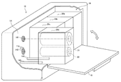
- FIG. 3 is a perspective view illustrating a state in which the ink ribbon cassette according to each embodiment of the invention is attached to the printer. It is a figure which shows the ink ribbon cassette which concerns on the 1st Embodiment of this invention. It is a figure which shows the ink ribbon cassette which concerns on the 2nd Embodiment of this invention. It is a figure which shows the ink ribbon cassette which concerns on the 3rd Embodiment of this invention.
- FIG. 1 is a schematic sectional view showing a color printer equipped with an ink ribbon cassette according to each embodiment of the present invention.
- This color printer is a printer for printing on a printing medium (paper) such as a label temporarily attached to a mount or a belt-like sheet for manufacturing a tag, and uses an ink ribbon ink by using a thermal head. Is printed on the paper.
- a printing medium paper
- a thermal head a thermal head
- a sheet 1 is rotatably supported on a sheet supply shaft 11 provided in a housing of a printer 10 as a roll sheet 2 wound in a roll shape.
- the paper 1 pulled out from the paper supply shaft 11 is supplied between a driving roller 12 that rotates by being driven by a motor provided in the housing, and a driven roller 13 that rotates as the driving roller 12 rotates. It is nipped and conveyed by the driving roller 12 and the driven roller 13.
- ink ribbon cassettes 20a to 20d are mounted on the frame 14 of the housing from the upstream side in the transport direction (right side in the figure) to the downstream side in the transport direction (left side in the figure).
- the ink ribbon cassette 20a is loaded with a yellow (yellow) ink ribbon
- the ink ribbon cassette 20b is loaded with a magenta ink ribbon
- the ink ribbon cassette 20c is loaded with a cyan ink ribbon.
- the ink ribbon cassette 20d is loaded with a black (black) ink ribbon. *
- the ink ribbon 23 is stretched between the ink ribbon supply shaft 21 and the ink ribbon take-up shaft 22.
- the ink ribbon winding shaft 22 is driven to rotate by a motor provided in the housing.
- the printer 10 has four platen rollers 15a to 15d and four thermal heads 16a to 16d corresponding to the four types of ink ribbon cassettes 20a to 20d.
- the thermal heads 16a to 16d are inserted into the ink ribbon cassettes 20a to 20d, respectively, and are arranged to face the platen rollers 15a to 15d, respectively.
- the unused ink ribbon 23 supported while being wound in a roll on the ink ribbon supply shaft 21 of the ink ribbon cassette 20a is supplied together with the paper 1 between the platen roller 15a and the thermal head 16a.
- the ink ribbon 23 is taken up by the ink ribbon take-up shaft 22.
- the platen roller 15a is driven and rotated by a motor provided in the housing, thereby conveying the paper 1 and the ink ribbon 23 in the same direction at the same speed.
- the thermal head 16a has a plurality of fine heating elements in the width direction that generate heat when an electric current flows. Printing is performed using a yellow ink ribbon loaded in the ink ribbon cassette 20a by applying a voltage to these heat generating elements to cause the heat generating elements to generate heat and transferring the ink on the ink ribbon 23 to the paper 1. Is done. *
- the platen rollers 15b to 15d are configured similarly to the platen roller 15a, and the thermal heads 16b to 16d are configured similarly to the thermal head 16a.
- the sheet 1 that has passed the position of the platen roller 15a sequentially passes the positions of the platen rollers 15b to 15d, and the magenta, cyan, and black ink ribbons loaded in the ink ribbon cassettes 20b to 20d, respectively, by the thermal heads 16b to 16d.
- the printing used is sequentially performed.
- the printed paper 1 is discharged from the paper discharge port. *
- the input unit 30 includes a plurality of operation keys and / or an interface connected to an external host computer, and is used to operate the printer 10.
- the control unit 40 includes, for example, a CPU and software, and controls the operation of each unit of the printer 10.
- the display unit 50 includes an LCD (liquid crystal display) panel or a plurality of LEDs (light emitting diodes) for displaying an error message or the like, and performs various displays based on signals supplied from the control unit 40.
- the power supply unit 60 supplies power to each unit of the printer 10. *
- the ink ribbon supply shaft 21 and the ink ribbon take-up shaft 22 are locked when the ink ribbon cassettes 20a to 20d are not attached to the printer 10, and the ink ribbon cassettes 20a to 20d are connected to the printer 10.
- the ink ribbon cassettes 20a to 20d are configured so that the ink ribbon supply shaft 21 and the ink ribbon take-up shaft 22 are unlocked when the ink ribbon supply shaft 21 and the ink ribbon take-up shaft 22 are unlocked.
- a plurality of openings are respectively formed at a plurality of different positions on the side surface (surface on the frame 14 side) of the cassette case of each ink ribbon cassette. These openings correspond to the color types of the ink ribbon. In this embodiment, since four color ink ribbons are used, the four openings formed on the side surface of the cassette case correspond to four colors of yellow, magenta, cyan, and black, respectively. *
- a plurality of pins 17a to 17d are provided at a plurality of regions where a plurality of ink ribbon cassettes 20a to 20d are mounted at different positions corresponding to the color type of the ink ribbon to be mounted. Are provided.
- the pins 17a to 17d are respectively inserted into openings formed at different positions for the plurality of ink ribbon cassettes 20a to 20d.
- the ink ribbon cassette is mounted in the wrong position, the ink ribbon supply shaft 21 and the ink ribbon take-up shaft 22 are not unlocked, and the ink ribbon supply shaft 21 and the ink ribbon take-up shaft 22 do not rotate.
- the rotation of the motor that drives the winding shaft 22 is also stopped.
- the control unit 40 detects the stop of the rotation of the motor and causes the display unit 50 to display an error regarding the ink ribbon cassette.
- FIG. 2 is a perspective view showing a state in which the ink ribbon cassette according to each embodiment of the present invention is attached to the printer.
- the platen roller and the thermal head are omitted.
- the printer 10 is provided with a storage unit 18 for storing the ink ribbon cassette.
- the ink ribbon cassette is attached / detached by opening the door 19 of the storage unit 18.
- FIG. 2 shows a state where the ink ribbon cassettes 20a to 20c are already mounted and the ink ribbon cassette 20d is to be mounted. *
- the plate 14 of the printer 10 is provided with a rotation shaft 141 that fits the ink ribbon supply shaft 21 and a rotation shaft 142 that fits the ink ribbon take-up shaft 22. Further, guide pins 143 and 144 for guiding the ink ribbon cassette are provided, and a pin 17d is provided at a position corresponding to the type (black) of the ink ribbon loaded in the ink ribbon cassette 20d. On the other hand, two guide holes into which guide pins 143 and 144 are inserted and a plurality of openings corresponding to a plurality of types of ink ribbons are formed on the side surface of the cassette case of the ink ribbon cassette 20d. *
- the pin 17d is located at the opening corresponding to the type (black) of the ink ribbon loaded in the ink ribbon cassette 20d. Since the ink ribbon is inserted, the ink ribbon supply shaft 21 and the ink ribbon take-up shaft 22 are unlocked in the ink ribbon cassette 20d.
- FIG. 3 is a view showing the ink ribbon cassette according to the first embodiment of the present invention.
- FIG. 3A is a side view of the ink ribbon cassette viewed from the side opposite to FIG. 1
- FIG. 3B is a side view of the ink ribbon cassette on the BB ′ plane shown in FIG.
- FIG. 3C is a cross-sectional view showing the positional relationship between the stopper of the ink ribbon cassette and the locking plate.
- an ink ribbon cassette 20a loaded with a yellow ink ribbon among the four types of ink ribbon cassettes 20a to 20d shown in FIG. 1 will be described. *
- the ink ribbon cassette 20a includes a cassette case 25 having side surfaces formed with a plurality of openings 24a to 24d at a plurality of different positions, and an unused ink ribbon.
- An ink ribbon supply shaft 21 that is rotatably supported by the cassette case 25 for supply and provided with a gear-like stopper 21a along the rotation direction, and rotates to the cassette case 25 to wind up the used ink ribbon.
- the ink ribbon take-up shaft 22 provided with a gear-like stopper 22a along the rotation direction and the ink ribbon supply shaft 21 and the ink ribbon take-up shaft 22 are locked by engaging with the stoppers 21a and 22a.
- a locking portion 26 to be included.
- the locking portion 26 includes a locking plate 261 that is rotatably supported by the cassette case 25 and a plate spring 262 that biases the locking plate 261.
- a coil spring may be used instead of the leaf spring.
- the locking plate 261 corresponds to the type of the ink ribbon 23, the engaging portion 26a that engages with the stopper 21a, the engaging portion 26b that engages with the stopper 22a. And an extended portion 26c extending to a predetermined position of the opening 24a.
- the leaf spring 262 biases the locking plate 261 so that the engaging portions 26a and 26b engage with the stoppers 21a and 22a, respectively.
- the stop plate 261 locks the ink ribbon supply shaft 21 and the ink ribbon take-up shaft 22. Accordingly, even if the ink ribbon cassette 20a is transported or the like, the ink ribbon 23 is not slackened, so that the ink ribbon 23 can be protected. In addition, if the position for mounting the ink ribbon cassette 20a is wrong, the ink ribbon supply shaft 21 and the ink ribbon take-up shaft 22 are not unlocked, and the ink ribbon supply shaft 21 and the ink ribbon take-up shaft 22 do not rotate. *
- FIG. 4 is a view showing an ink ribbon cassette according to the second embodiment of the present invention.
- 4A is a side view of the ink ribbon cassette as viewed from the opposite side to FIG. 1
- FIG. 4B is a diagram showing the positional relationship between the stopper of the ink ribbon cassette and the locking plate.
- an ink ribbon cassette 20a loaded with a yellow ink ribbon among the four types of ink ribbon cassettes 20a to 20d shown in FIG. 1 will be described. *
- the ink ribbon cassette 20a includes a cassette case 25 having side surfaces in which a plurality of openings 24a to 24d and 28a to 28d are respectively formed at a plurality of different positions, and an unused ink ribbon.
- An ink ribbon supply shaft 21 that is rotatably supported by the cassette case 25 for supply and provided with a gear-like stopper 21a along the rotation direction, and rotates to the cassette case 25 to wind up the used ink ribbon.
- the ink ribbon take-up shaft 22 provided with a gear-like stopper 22a along the rotation direction and the ink ribbon supply shaft 21 and the ink ribbon take-up shaft 22 are locked by engaging with the stoppers 21a and 22a. And a locking portion 27 to be included.
- the locking portion 27 includes a locking plate 271 that is supported by the cassette case 25 so as to be movable in parallel, and plate springs 272 and 273 that bias the locking plate 271.
- a coil spring may be used instead of the leaf spring.
- the locking plate 271 is located at the positions of an engagement portion 27a that engages with the stopper 21a, an engagement portion 27b that engages with the stopper 22a, and openings 24a and 28a that are predetermined according to the type of the ink ribbon 23.
- Each has extended portions 27c and 27d extending. *
- the leaf springs 272 and 273 bias the locking plate 271 so that the engaging portions 27a and 27b engage with the stoppers 21a and 22a, respectively.
- the locking plate 271 locks the ink ribbon supply shaft 21 and the ink ribbon take-up shaft 22. Accordingly, even if the ink ribbon cassette 20a is transported or the like, the ink ribbon 23 is not slackened, so that the ink ribbon 23 can be protected. In addition, if the position for mounting the ink ribbon cassette 20a is wrong, the ink ribbon supply shaft 21 and the ink ribbon take-up shaft 22 are not unlocked, and the ink ribbon supply shaft 21 and the ink ribbon take-up shaft 22 do not rotate. *
- two pins 17a having a tapered shape as shown in FIG. 4B are provided on the frame 14 of the printer.
- the ink ribbon cassette 20a is mounted at the correct position of the printer, as shown in FIGS. 4A and 4B, the plurality of openings 24a to 24d and 28a to 28d formed in the side surface of the cassette case 25 Since the two pins 17a provided on the printer frame 14 are inserted into the openings 24a and 28a determined in advance corresponding to the yellow ink ribbon, the pins 17a abut against the extending portions 27c and 27d. As a result, the locking plate 271 moves substantially parallel to the negative direction in the Y-axis direction, and the lock of the ink ribbon supply shaft 21 and the ink ribbon take-up shaft 22 is released. *
- FIG. 5 is a view showing an ink ribbon cassette according to the third embodiment of the present invention.
- FIG. 5A is a side view of the ink ribbon cassette viewed from the side opposite to FIG. 1
- FIG. 5B is a diagram showing the positional relationship between the stopper of the ink ribbon cassette and the locking plate.
- an ink ribbon cassette 20a loaded with a yellow ink ribbon among the four types of ink ribbon cassettes 20a to 20d shown in FIG. 1 will be described. *
- the ink ribbon cassette 20a is provided with a cassette case 25 having a side surface in which a plurality of openings 24a to 24d are formed at a plurality of different positions, and an unused ink ribbon.
- An ink ribbon supply shaft 21 that is rotatably supported by the cassette case 25 and provided with a gear-like stopper 21a along the rotation direction, and is rotatably supported by the cassette case 25 to wind up the used ink ribbon.
- the ink ribbon take-up shaft 22 provided with a gear-like stopper 22a along the rotation direction, and the engaging portion that engages with the stoppers 21a and 22a to lock the ink ribbon supply shaft 21 and the ink ribbon take-up shaft 22 29.
- the locking portion 29 includes a locking plate 291 that is supported by the cassette case 25 so as to be movable in parallel, and a coil spring 292 that biases the locking plate 291.
- a plate spring may be used instead of the coil spring.
- the locking plate 291 includes an engagement portion 29a that engages with the stopper 21a, an engagement portion 29b that engages with the stopper 22a, and a position of at least one opening 24a that is predetermined according to the type of the ink ribbon 23. Extending part 29c. *
- the coil spring 292 biases the locking plate 291 so that the engaging portions 29a and 29b engage with the stoppers 21a and 22a, respectively.
- the stop plate 291 locks the ink ribbon supply shaft 21 and the ink ribbon take-up shaft 22. Accordingly, even if the ink ribbon cassette 20a is transported or the like, the ink ribbon 23 is not slackened, so that the ink ribbon 23 can be protected. In addition, if the position for mounting the ink ribbon cassette 20a is wrong, the ink ribbon supply shaft 21 and the ink ribbon take-up shaft 22 are not unlocked, and the ink ribbon supply shaft 21 and the ink ribbon take-up shaft 22 do not rotate. *
- a pin 17a having a tapered shape as shown in FIG. 5B is provided on the frame 14 of the printer.
- yellow ink is discharged from the plurality of openings 24a to 24d formed on the side surface of the cassette case 25. Since the pin 17a provided on the printer frame 14 is inserted into the predetermined opening 24a corresponding to the ribbon, the locking plate 291 is moved in the Z-axis direction by the pin 17a coming into contact with the extending portion 29c.
- the ink ribbon supply shaft 21 and the ink ribbon take-up shaft 22 are unlocked.
- the locking portion serves both as an ink ribbon slack prevention mechanism and a mounting position detection mechanism, and thus a simple mechanism prevents ink ribbon slack and erroneous printing. can do. Further, since the mold of the cassette case made of resin or the like can be made common to a plurality of types of ink ribbons, an increase in cost when the present invention is implemented can be suppressed.
Landscapes
- Impression-Transfer Materials And Handling Thereof (AREA)
- Electronic Switches (AREA)
Abstract
【課題】簡単な機構によって、インクリボンカセットがカラープリンタに装着されていないときにインクリボンの弛みを防止すると共に、インクリボンカセットをカラープリンタに装着する際に位置を間違えても誤印字を防止する。【解決手段】このインクリボンカセットは、複数の異なる位置に複数の開口がそれぞれ形成されたカセットケースと、カセットケースに回転可能に支持され、回転方向に沿って歯車状のストッパーが設けられたインクリボン供給軸及びインクリボン巻取り軸と、ストッパーに係合してインクリボン供給軸及びインクリボン巻取り軸をロックし、カセットケースに形成された複数の開口の内からインクリボンの種類に対応して予め定められた少なくとも1つの開口に少なくとも1つのピンが挿入されたときにインクリボン供給軸及びインクリボン巻取り軸のロックを解除する係止部とを含む。
Description
本発明は、印字を行う際に用いられる各色のインクリボンが装填されたインクリボンカセット、及び、そのようなインクリボンカセットを用いて複数の色で印字を行うカラープリンタに関する。
例えば、台紙に仮着されたラベル、又は、タグ製造用の帯状のシート等の被印字媒体(以下、「用紙」ともいう)に印字を行うプリンタとして、サーマルヘッドを用いてインクリボンのインクを用紙に転写することにより印字を行うサーマル転写式プリンタが用いられている。サーマル転写式プリンタにおいては、用紙とインクリボンとを同一方向に同一速度で搬送しながら、サーマルヘッドの発熱体が発生する熱によってインクリボンのインクを用紙に転写することにより印字が行われる。
サーマル転写式プリンタにおいて複数の色で印字を行うためには、複数色のインクリボンが必要となるので、一般的に、各色のインクリボンが装填されたインクリボンカセットが用いられる。しかしながら、複数種類のインクリボンカセットをカラープリンタに装着する際に、インクリボンカセットを装着する位置を間違えると、誤った色で印字が行われてしまう。
また、インクリボンカセットを運搬等する際に、インクリボンに弛みが生じると、インクリボンカセットをカラープリンタに装着する際の操作性が悪化したり、インクリボンに損傷が及んでしまうという問題が発生する。そのような問題を解決するために、不使用時にインクリボンにブレーキを掛ける機構が提案されている。
関連する技術として、特許文献1には、インクリボンの弛みを安定的に防止するインクインクリボンカセットが開示されている。このインクリボンカセットは、リボン収納部、リボン送り出し通路、及び、リボン受け入れ通路が一体化したケースと、一部がリボン送り出し通路からリボン収納部の外に出てリボン受け入れ通路を通じて再びリボン収納部内に循環している無終端のインクリボンと、リボン収納部内に設けられているリボン走行機構とを備えている。
このリボン走行機構においては、通過するインクリボンの一面に駆動ギアが当接し、他面に走行方向後方で引き入れ従動ギア、先方で押込従動ギアが当接し、インクリボンを間に挟んで駆動ギアが各従動ギアに噛み合って設けられており、押込従動ギアの回転軸が、駆動ギアの回転軸を中心点にして、引き入れ従動ギア及び押込従動ギア同士が噛み合う点まで弧状に形成されている円弧ガイドに摺動可能に係合している。
特許文献1のインクリボンカセットによれば、インクリボンが逆方向に走行しようとすると、駆動ギア、引き入れ従動ギア、及び、押込従動ギアが三すくみの状態で噛み合い、リボン走行機構によるインクリボンの噛み込みが防止される。しかしながら、このように複雑なリボン走行機構を採用すれば、インクリボンカセットのコストが上昇してしまう。
そこで、上記の点に鑑み、本発明は、インクリボンカセットにおいて、簡単な機構によって、インクリボンカセットがカラープリンタに装着されていないときにインクリボンの弛みを防止すると共に、インクリボンカセットをカラープリンタに装着する際に位置を間違えても誤印字を防止することを目的とする。
以上の課題を解決するため、本発明の1つの観点に係るインクリボンカセットは、カラープリンタにおいて印字に用いられるインクリボンが装填されたインクリボンカセットであって、複数の異なる位置に複数の開口がそれぞれ形成されたカセットケースと、未使用のインクリボンを供給するためにカセットケースに回転可能に支持され、回転方向に沿って歯車状の第1のストッパーが設けられたインクリボン供給軸と、使用済みのインクリボンを巻き取るためにカセットケースに回転可能に支持され、回転方向に沿って歯車状の第2のストッパーが設けられたインクリボン巻取り軸と、第1及び第2のストッパーに係合してインクリボン供給軸及びインクリボン巻取り軸をロックし、カセットケースに形成された複数の開口の内からインクリボンの種類に対応して予め定められた少なくとも1つの開口に少なくとも1つのピンが挿入されたときにインクリボン供給軸及びインクリボン巻取り軸のロックを解除する係止部とを具備する。
本発明の1つの観点によれば、係止部が、第1及び第2のストッパーに係合してインクリボン供給軸及びインクリボン巻取り軸をロックし、カセットケースに形成された複数の開口の内からインクリボンの種類に対応して予め定められた少なくとも1つの開口に少なくとも1つのピンが挿入されたときにインクリボン供給軸及びインクリボン巻取り軸のロックを解除するので、インクリボンカセットがカラープリンタに装着されていないときにインクリボンの弛みを防止すると共に、インクリボンカセットをカラープリンタに装着する際に位置を間違えても誤印字を防止することができる。
以下、本発明の実施形態について、図面を参照しながら詳しく説明する。なお、同一の構成要素には同一の符号を付して、重複する説明を省略する。 図1は、本発明の各実施形態に係るインクリボンカセットが装着されたカラープリンタを示す概略断面図である。このカラープリンタは、台紙に仮着されたラベル、又は、タグ製造用の帯状のシート等の被印字媒体(用紙)に印字を行うためのプリンタであって、サーマルヘッドを用いてインクリボンのインクを用紙に転写することにより印字を行う。以下においては、4色のインクリボンがそれぞれ装填された4種類のインクリボンカセットを用いて用紙に印字を行う場合を例にとって説明する。
図1に示すように、用紙1が、ロール状に巻回されたロール紙2として、プリンタ10の筐体に設けられた用紙供給軸11に回転可能に支持されている。用紙供給軸11から引き出された用紙1は、筐体内に設けられたモータによって駆動されて回転する駆動ローラ12と、駆動ローラ12の回転に伴って回転する従動ローラ13との間に供給され、駆動ローラ12と従動ローラ13とによって挟持搬送される。
また、筐体のフレーム14には、搬送方向上流側(図中右側)から搬送方向下流側(図中左側)に向けて、4種類のインクリボンカセット20a~20dが装着されている。例えば、インクリボンカセット20aには、イエロー(黄色)のインクリボンが装填されており、インクリボンカセット20bには、マゼンタのインクリボンが装填されており、インクリボンカセット20cには、シアンのインクリボンが装填されており、インクリボンカセット20dには、ブラック(黒色)のインクリボンが装填されている。
インクリボンカセット20a~20dの各々において、インクリボン23が、インクリボン供給軸21とインクリボン巻取り軸22との間に架け渡されている。インクリボン巻取り軸22は、筐体内に設けられたモータによって駆動されて回転する。
プリンタ10は、4種類のインクリボンカセット20a~20dに対応して、4つのプラテンローラ15a~15dと、4つのサーマルヘッド16a~16dとを有している。サーマルヘッド16a~16dは、インクリボンカセット20a~20dの内部にそれぞれ挿入され、プラテンローラ15a~15dにそれぞれ対向して配置される。
インクリボンカセット20aのインクリボン供給軸21にロール状に巻回された状態で支持された未使用のインクリボン23は、プラテンローラ15aとサーマルヘッド16aとの間に用紙1と共に供給され、転写後のインクリボン23は、インクリボン巻取り軸22によって巻き取られる。
プラテンローラ15aは、筐体内に設けられたモータによって駆動されて回転することにより、用紙1及びインクリボン23を同一方向に同一速度で搬送する。サーマルヘッド16aは、電流を流すことによって発熱する複数の微細な発熱体を幅方向に有している。これらの発熱体に電圧を印加して電流を流すことにより発熱体を発熱させ、インクリボン23のインクを用紙1に転写することにより、インクリボンカセット20aに装填されたイエローのインクリボンを用いた印字が行われる。
プラテンローラ15b~15dもプラテンローラ15aと同様に構成され、サーマルヘッド16b~16dもサーマルヘッド16aと同様に構成されている。プラテンローラ15aの位置を通過した用紙1は、プラテンローラ15b~15dの位置を順次通過し、サーマルヘッド16b~16dによって、インクリボンカセット20b~20dにそれぞれ装填されたマゼンタ、シアン、ブラックのインクリボンを用いた印字が順次行われる。印字が完了した用紙1は、用紙排出口から排出される。
入力部30は、複数の操作キー、及び/又は、外部のホストコンピュータに接続されるインタフェースを含んでおり、プリンタ10を操作するために用いられる。制御部40は、例えば、CPUとソフトウェアを含んでおり、プリンタ10の各部の動作を制御する。表示部50は、エラーメッセージ等を表示するためのLCD(液晶表示)パネル又は複数のLED(発光ダイオード)を含んでおり、制御部40から供給される信号に基づいて各種の表示を行う。電源部60は、プリンタ10の各部に電力を供給する。
このように複数種類のインクリボンカセットを用いるカラープリンタにおいては、複数種類のインクリボンカセットをプリンタに装着する際に、インクリボンカセットを装着する位置を間違えると、誤った色で印字が行われてしまう。また、インクリボンカセットを運搬等する際に、インクリボンに弛みが生じると、インクリボンカセットをカラープリンタに装着する際の操作性が悪化したり、インクリボンに損傷が及んでしまう。
そこで、本発明の各実施形態においては、インクリボンカセット20a~20dがプリンタ10に装着されていないときにインクリボン供給軸21及びインクリボン巻取り軸22がロックされ、インクリボンカセット20a~20dがプリンタ10の正しい位置に装着されたときにインクリボン供給軸21及びインクリボン巻取り軸22のロックが解除されるように、インクリボンカセット20a~20dが構成されている。
そのために、各々のインクリボンカセットのカセットケースの側面(フレーム14側の面)における複数の異なる位置に、複数の開口がそれぞれ形成されている。それらの開口は、インクリボンの色の種類に対応している。本実施形態においては、4色のインクリボンが用いられるので、カセットケースの側面に形成された4つの開口が、イエロー、マゼンタ、シアン、ブラックの4色にそれぞれ対応している。
また、プリンタ10のフレーム14において、複数のインクリボンカセット20a~20dが装着される複数の領域には、装着されるべきインクリボンの色の種類に対応して異なる位置に、複数のピン17a~17dがそれぞれ設けられている。それらのピン17a~17dは、複数のインクリボンカセット20a~20dについて異なる位置に形成された開口にそれぞれ挿入される。インクリボンカセットが
プリンタ10の正しい位置に装着されると、そのインクリボンカセットに装填されたインクリボンの色に対応する開口にピンが挿入されるので、インクリボン供給軸21及びインクリボン巻取り軸22のロックが解除される。
プリンタ10の正しい位置に装着されると、そのインクリボンカセットに装填されたインクリボンの色に対応する開口にピンが挿入されるので、インクリボン供給軸21及びインクリボン巻取り軸22のロックが解除される。
一方、インクリボンカセットを装着する位置を間違えると、インクリボン供給軸21及びインクリボン巻取り軸22のロックが解除されず、インクリボン供給軸21及びインクリボン巻取り軸22が回転しないので、インクリボン巻取り軸22を駆動するモータの回転も停止する。制御部40は、モータの回転の停止を検出して、当該インクリボンカセットに関するエラー表示を表示部50に行わせる。
例えば、イエローのインクリボンが装填されたインクリボンカセットの装着位置を間違えた場合には、表示部50のLCDパネルにおいて、「イエローインクリボンカセットエラー」と表示される。これにより、オペレータは、イエローのインクリボンカセットの装着位置を間違えたか、又は、イエローのインクリボンを使い切ったことを認識することができる。
以上においては、インクリボンの1つの種類に対応して、カセットケースの側面に1つの開口が形成され、プリンタに1つのピンが設けられる場合について説明したが、インクリボンの1つの種類に対応して、カセットケースの側面に複数の開口が形成され、プリンタに複数のピンを設けるようにしても良い。
図2は、本発明の各実施形態に係るインクリボンカセットがプリンタに装着される状態を示す斜視図である。なお、図2においては、プラテンローラ及びサーマルヘッドを省略している。図2に示すように、プリンタ10には、インクリボンカセットを収納するための収納部18が設けられている。収納部18の扉19を開けることにより、インクリボンカセットの着脱が行われる。図2においては、インクリボンカセット20a~20cが既に装着され、インクリボンカセット20dがこれから装着される状態が示されている。
プリンタ10のプレーム14には、インクリボン供給軸21に嵌合する回転軸141と、インクリボン巻取り軸22に嵌合する回転軸142とが設けられている。また、インクリボンカセットをガイドするためのガイドピン143及び144が設けられ、インクリボンカセット20dに装填されているインクリボンの種類(ブラック)に対応する位置にピン17dが設けられている。一方、インクリボンカセット20dのカセットケースの側面には、ガイドピン143及び144が挿入される2つのガイド孔と、インクリボンの複数の種類に対応する複数の開口とが形成されている。
インクリボンカセット20dが、ガイドピン143及び144にガイドされながらプリンタ10の正しい位置に装着されると、インクリボンカセット20dに装填されているインクリボンの種類(ブラック)に対応する位置の開口にピン17dが挿入されるので、インクリボンカセット20dにおいてインクリボン供給軸21及びインクリボン巻取り軸22のロックが解除される。
次に、本発明の各実施形態に係るインクリボンカセットについて詳しく説明する。 図3は、本発明の第1の実施形態に係るインクリボンカセットを示す図である。図3の(a)は、インクリボンカセットを図1とは反対側から見た側面図であり、図3の(b)は、図3の(a)に示すB-B’面におけるインクリボンカセットの断面図であり、図3の(c)は、インクリボンカセットのストッパーと係止板との位置関係を示す図である。ここでは、例として、図1に示す4種類のインクリボンカセット20a~20dの内で、イエローのインクリボンが装填されたインクリボンカセット20aについて説明する。
図3の(a)及び(b)に示すように、インクリボンカセット20aは、複数の異なる位置に複数の開口24a~24dがそれぞれ形成された側面を有するカセットケース25と、未使用のインクリボンを供給するためにカセットケース25に回転可能に支持され、回転方向に沿って歯車状のストッパー21aが設けられたインクリボン供給軸21と、使用済みのインクリボンを巻き取るためにカセットケース25に回転可能に支持され、回転方向に沿って歯車状のストッパー22aが設けられたインクリボン巻取り軸22と、ストッパー21a及び22aに係合してインクリボン供給軸21及びインクリボン巻取り軸22をロックする係止部26とを含んでいる。
係止部26は、カセットケース25に回動可能に支持された係止板261と、係止板261を付勢する板ばね262とによって構成される。なお、板ばねの替わりにコイルスプリングを用いるようにしても良い。図3の(a)に示すように、係止板261は、ストッパー21aに係合する係合部分26aと、ストッパー22aに係合する係合部分26bと、インクリボン23の種類に対応して予め定められた開口24aの位置に延在する延在部分26cとを有している。
インクリボンカセット20aがプリンタの正しい位置に装着されていない状態においては、係合部分26a及び26bがストッパー21a及び22aにそれぞれ係合するように板ばね262が係止板261を付勢するので、係止板261がインクリボン供給軸21及びインクリボン巻取り軸22をロックする。従って、インクリボンカセット20aを運搬等してもインクリボン23に弛みが生じないので、インクリボン23を保護することができる。また、インクリボンカセット20aを装着する位置を間違えると、インクリボン供給軸21及びインクリボン巻取り軸22のロックが解除されず、インクリボン供給軸21及びインクリボン巻取り軸22が回転しない。
インクリボンカセット20aがプリンタの正しい位置に装着されると、図3の(a)及び(b)に示すように、カセットケース25の側面に形成された複数の開口24a~24dの内からイエローのインクリボン23に対応して予め定められた開口24aに、プリンタのフレーム14に設けられたピン17aが挿入されるので、ピン17aが延在部分26cに当接することにより、図3の(c)に示すように、係止板261が回動して、インクリボン供給軸21及びインクリボン巻取り軸22のロックを解除する。
図4は、本発明の第2の実施形態に係るインクリボンカセットを示す図である。図4の(a)は、インクリボンカセットを図1とは反対側から見た側面図であり、図4の(b)は、インクリボンカセットのストッパーと係止板との位置関係を示す図である。ここでは、例として、図1に示す4種類のインクリボンカセット20a~20dの内で、イエローのインクリボンが装填されたインクリボンカセット20aについて説明する。
図4の(a)に示すように、インクリボンカセット20aは、複数の異なる位置に複数の開口24a~24d及び28a~28dがそれぞれ形成された側面を有するカセットケース25と、未使用のインクリボンを供給するためにカセットケース25に回転可能に支持され、回転方向に沿って歯車状のストッパー21aが設けられたインクリボン供給軸21と、使用済みのインクリボンを巻き取るためにカセットケース25に回転可能に支持され、回転方向に沿って歯車状のストッパー22aが設けられたインクリボン巻取り軸22と、ストッパー21a及び22aに係合してインクリボン供給軸21及びインクリボン巻取り軸22をロックする係止部27とを含んでいる。
係止部27は、カセットケース25に平行移動可能に支持された係止板271と、係止板271を付勢する板ばね272及び273とによって構成される。なお、板ばねの替わりにコイルスプリングを用いるようにしても良い。係止板271は、ストッパー21aに係合する係合部分27aと、ストッパー22aに係合する係合部分27bと、インクリボン23の種類に対応して予め定められた開口24a及び28aの位置にそれぞれ延在する延在部分27c及び27dとを有している。
インクリボンカセット20aがプリンタの正しい位置に装着されていない状態においては、係合部分27a及び27bがストッパー21a及び22aにそれぞれ係合するように板ばね272及び273が係止板271を付勢するので、係止板271がインクリボン供給軸21及びインクリボン巻取り軸22をロックする。従って、インクリボンカセット20aを運搬等してもインクリボン23に弛みが生じないので、インクリボン23を保護することができる。また、インクリボンカセット20aを装着する位置を間違えると、インクリボン供給軸21及びインクリボン巻取り軸22のロックが解除されず、インクリボン供給軸21及びインクリボン巻取り軸22が回転しない。
本実施形態においては、図4の(b)に示すようなテーパー形状を有する2つのピン17aが、プリンタのフレーム14に設けられている。インクリボンカセット20aがプリンタの正しい位置に装着されると、図4の(a)及び(b)に示すように、カセットケース25の側面に形成された複数の開口24a~24d及び28a~28dの内からイエローのインクリボンに対応して予め定められた開口24a及び28aに、プリンタのフレーム14に設けられた2つのピン17aが挿入されるので、ピン17aが延在部分27c及び27dに当接することにより、係止板271がY軸方向の負の向きに略平行に移動して、インクリボン供給軸21及びインクリボン巻取り軸22のロックを解除する。
図5は、本発明の第3の実施形態に係るインクリボンカセットを示す図である。図5の(a)は、インクリボンカセットを図1とは反対側から見た側面図であり、図5の(b)は、インクリボンカセットのストッパーと係止板との位置関係を示す図である。ここでは、例として、図1に示す4種類のインクリボンカセット20a~20dの内で、イエローのインクリボンが装填されたインクリボンカセット20aについて説明する。
図5の(a)に示すように、インクリボンカセット20aは、複数の異なる位置に複数の開口24a~24dがそれぞれ形成された側面を有するカセットケース25と、未使用のインクリボンを供給するためにカセットケース25に回転可能に支持され、回転方向に沿って歯車状のストッパー21aが設けられたインクリボン供給軸21と、使用済みのインクリボンを巻き取るためにカセットケース25に回転可能に支持され、回転方向に沿って歯車状のストッパー22aが設けられたインクリボン巻取り軸22と、ストッパー21a及び22aに係合してインクリボン供給軸21及びインクリボン巻取り軸22をロックする係止部29とを含んでいる。
係止部29は、カセットケース25に平行移動可能に支持された係止板291と、係止板291を付勢するコイルスプリング292とによって構成される。なお、コイルスプリングの替わりに板ばねを用いるようにしても良い。係止板291は、ストッパー21aに係合する係合部分29aと、ストッパー22aに係合する係合部分29bと、インクリボン23の種類に対応して予め定められた少なくとも1つの開口24aの位置に延在する延在部分29cとを有している。
インクリボンカセット20aがプリンタの正しい位置に装着されていない状態においては、係合部分29a及び29bがストッパー21a及び22aにそれぞれ係合するようにコイルスプリング292が係止板291を付勢するので、係止板291がインクリボン供給軸21及びインクリボン巻取り軸22をロックする。従って、インクリボンカセット20aを運搬等してもインクリボン23に弛みが生じないので、インクリボン23を保護することができる。また、インクリボンカセット20aを装着する位置を間違えると、インクリボン供給軸21及びインクリボン巻取り軸22のロックが解除されず、インクリボン供給軸21及びインクリボン巻取り軸22が回転しない。
本実施形態においては、図5の(b)に示すようなテーパー形状を有するピン17aが
、プリンタのフレーム14に設けられている。インクリボンカセット20aがプリンタの正しい位置に装着されると、図5の(a)及び(b)に示すように、カセットケース25の側面に形成された複数の開口24a~24dの内からイエローのインクリボンに対応して予め定められた開口24aに、プリンタのフレーム14に設けられたピン17aが挿入されるので、ピン17aが延在部分29cに当接することにより、係止板291がZ軸方向の負の向きに略平行に移動して、インクリボン供給軸21及びインクリボン巻取り軸22のロックを解除する。
、プリンタのフレーム14に設けられている。インクリボンカセット20aがプリンタの正しい位置に装着されると、図5の(a)及び(b)に示すように、カセットケース25の側面に形成された複数の開口24a~24dの内からイエローのインクリボンに対応して予め定められた開口24aに、プリンタのフレーム14に設けられたピン17aが挿入されるので、ピン17aが延在部分29cに当接することにより、係止板291がZ軸方向の負の向きに略平行に移動して、インクリボン供給軸21及びインクリボン巻取り軸22のロックを解除する。
以上説明したような各実施形態に係るインクリボンカセットによれば、係止部がインクリボンの弛み防止機構と装着位置の検出機構とを兼ねるので、簡単な機構によってインクリボンの弛みや誤印字を防止することができる。また、樹脂等で作製されるカセットケースの金型を複数種類のインクリボンについて共通にすることができるので、本発明を実施する際のコストの上昇を抑えることができる。
1 用紙 2 ロール紙 10 プリンタ 11 用紙供給軸 12 駆動ローラ 13 従動ローラ 14 フレーム 141、142 回転軸 143、144 ガイドピン 15a~15d プラテンローラ 16a~16d サーマルヘッド 17a~17d ピン 18 収納部 19 扉 20a~20d インクリボンカセット 21 インクリボン供給軸 21a、22a ストッパー 22 インクリボン巻取り軸 23 インクリボン 24a~24d、28a~28d 開口 25 カセットケース 26、27、29 係止部 26a、26b、27a、27b、29a、29b 係合部分 26c、27c、27d、29c 延在部分 261、271、291 係止板 262、272、273 板ばね 292 コイルスプリング 30 入力部 40 制御部 50 表示部 60 電源部
Claims (6)
- カラープリンタにおいて印字に用いられるインクリボンが装填されたインクリボンカセットであって、 複数の異なる位置に複数の開口がそれぞれ形成されたカセットケースと、 未使用のインクリボンを供給するために前記カセットケースに回転可能に支持され、回転方向に沿って歯車状の第1のストッパーが設けられたインクリボン供給軸と、 使用済みのインクリボンを巻き取るために前記カセットケースに回転可能に支持され、回転方向に沿って歯車状の第2のストッパーが設けられたインクリボン巻取り軸と、 前記第1及び第2のストッパーに係合して前記インクリボン供給軸及び前記インクリボン巻取り軸をロックし、前記カセットケースに形成された複数の開口の内から前記インクリボンの種類に対応して予め定められた少なくとも1つの開口に少なくとも1つのピンが挿入されたときに前記インクリボン供給軸及び前記インクリボン巻取り軸のロックを解除する係止部と、を具備するインクリボンカセット。
- 前記カセットケースに形成された複数の開口が、インクリボンの色の種類に対応しており、前記カセットケースに装填されたインクリボンの色に対応する少なくとも1つの開口に少なくとも1つのピンが挿入されたときに、前記係止部が前記インクリボン供給軸及び前記インクリボン巻取り軸のロックを解除する、請求項1記載のインクリボンカセット。
- 前記係止部が、 前記第1のストッパーに係合する第1の係合部分と、前記第2のストッパーに係合する第2の係合部分と、前記インクリボンの種類に対応して予め定められた少なくとも1つの開口の位置に延在する延在部分とを有し、前記カセットケースに回動可能に支持された係止板と、 前記第1及び第2の係合部分が前記第1及び第2のストッパーにそれぞれ係合して前記インクリボン供給軸及び前記インクリボン巻取り軸をロックするように前記係止板を付勢するばねと、を有し、前記インクリボンの種類に対応して予め定められた少なくとも1つの開口に挿入された少なくとも1つのピンが前記延在部分に当接することにより、前記係止板が回動して前記インクリボン供給軸及び前記インクリボン巻取り軸のロックを解除する、請求項1又は2記載のインクリボンカセット。
- 前記係止部が、 前記第1のストッパーに係合する第1の係合部分と、前記第2のストッパーに係合する第2の係合部分と、前記インクリボンの種類に対応して予め定められた少なくとも1つの開口の位置に延在する延在部分とを有し、前記カセットケースに平行移動可能に支持された係止板と、 前記第1及び第2の係合部分が前記第1及び第2のストッパーにそれぞれ係合して前記インクリボン供給軸及び前記インクリボン巻取り軸をロックするように前記係止板を付勢するばねと、を有し、前記インクリボンの種類に対応して予め定められた少なくとも1つの開口に挿入された少なくとも1つのピンが前記延在部分に当接することにより、前記係止板が略平行に移動して前記インクリボン供給軸及び前記インクリボン巻取り軸のロックを解除する、請求項1又は2記載のインクリボンカセット。
- 被印字媒体を搬送して印字を行うカラープリンタであって、 請求項1~4のいずれか1項記載の複数のインクリボンカセットが装着され、前記複数のインクリボンカセットについて異なる位置に形成された開口に挿入される複数のピンが設けられた筐体と、 前記筐体内に設けられたモータによって駆動されて回転することにより、前記被印字媒体及び複数のインクリボンを搬送する複数のプラテンローラと、 前記複数のプラテンローラにそれぞれ対向して配置され、前記複数のインクリボンカセットに装填されたインクリボンをそれぞれ用いて前記被印字媒体に印字を行う複数のサーマルヘッドと、を具備するカラープリンタ。
- 前記複数のインクリボンカセットの内のいずれかのインクリボンカセットにおいて前記インクリボン巻取り軸が回転しないときに、当該インクリボンカセットに関するエラー表示を表示部に行わせる制御部をさらに具備する、請求項5記載のカラープリンタ。
Applications Claiming Priority (2)
| Application Number | Priority Date | Filing Date | Title |
|---|---|---|---|
| JP2010-076252 | 2010-03-29 | ||
| JP2010076252A JP5502555B2 (ja) | 2010-03-29 | 2010-03-29 | インクリボンカセット及びそれを用いるカラープリンタ |
Publications (1)
| Publication Number | Publication Date |
|---|---|
| WO2011121684A1 true WO2011121684A1 (ja) | 2011-10-06 |
Family
ID=44711481
Family Applications (1)
| Application Number | Title | Priority Date | Filing Date |
|---|---|---|---|
| PCT/JP2010/006214 Ceased WO2011121684A1 (ja) | 2010-03-29 | 2010-10-20 | インクリボンカセット及びそれを用いるカラープリンタ |
Country Status (2)
| Country | Link |
|---|---|
| JP (1) | JP5502555B2 (ja) |
| WO (1) | WO2011121684A1 (ja) |
Citations (9)
| Publication number | Priority date | Publication date | Assignee | Title |
|---|---|---|---|---|
| JPS59156756A (ja) * | 1983-02-25 | 1984-09-06 | Ricoh Co Ltd | インクカ−トリツジ装填装置 |
| JPS61120552U (ja) * | 1985-01-16 | 1986-07-30 | ||
| JPH0323970A (ja) * | 1989-06-20 | 1991-01-31 | Mitsubishi Electric Corp | サーマルラインプリンタ |
| JPH04193554A (ja) * | 1990-11-27 | 1992-07-13 | Ricoh Co Ltd | サーマルカラープリンタ |
| JPH10193730A (ja) * | 1996-12-27 | 1998-07-28 | Victor Co Of Japan Ltd | インクシートカセット |
| JP2002096517A (ja) * | 2000-09-25 | 2002-04-02 | Sony Corp | インクリボンカートリッジ |
| JP2004188810A (ja) * | 2002-12-12 | 2004-07-08 | Pilot Corporation | インクリボンコア |
| JP2006062278A (ja) * | 2004-08-30 | 2006-03-09 | Alps Electric Co Ltd | インクリボンカセットおよびこれを用いたプリンタ装置 |
| JP2007230157A (ja) * | 2006-03-02 | 2007-09-13 | Sony Corp | プリンタ装置 |
-
2010
- 2010-03-29 JP JP2010076252A patent/JP5502555B2/ja not_active Expired - Fee Related
- 2010-10-20 WO PCT/JP2010/006214 patent/WO2011121684A1/ja not_active Ceased
Patent Citations (9)
| Publication number | Priority date | Publication date | Assignee | Title |
|---|---|---|---|---|
| JPS59156756A (ja) * | 1983-02-25 | 1984-09-06 | Ricoh Co Ltd | インクカ−トリツジ装填装置 |
| JPS61120552U (ja) * | 1985-01-16 | 1986-07-30 | ||
| JPH0323970A (ja) * | 1989-06-20 | 1991-01-31 | Mitsubishi Electric Corp | サーマルラインプリンタ |
| JPH04193554A (ja) * | 1990-11-27 | 1992-07-13 | Ricoh Co Ltd | サーマルカラープリンタ |
| JPH10193730A (ja) * | 1996-12-27 | 1998-07-28 | Victor Co Of Japan Ltd | インクシートカセット |
| JP2002096517A (ja) * | 2000-09-25 | 2002-04-02 | Sony Corp | インクリボンカートリッジ |
| JP2004188810A (ja) * | 2002-12-12 | 2004-07-08 | Pilot Corporation | インクリボンコア |
| JP2006062278A (ja) * | 2004-08-30 | 2006-03-09 | Alps Electric Co Ltd | インクリボンカセットおよびこれを用いたプリンタ装置 |
| JP2007230157A (ja) * | 2006-03-02 | 2007-09-13 | Sony Corp | プリンタ装置 |
Also Published As
| Publication number | Publication date |
|---|---|
| JP2011207012A (ja) | 2011-10-20 |
| JP5502555B2 (ja) | 2014-05-28 |
Similar Documents
| Publication | Publication Date | Title |
|---|---|---|
| JP6247011B2 (ja) | 印刷装置 | |
| US9925795B2 (en) | Media processing device with enhanced media and ribbon loading and unloading features | |
| KR101532396B1 (ko) | 프린트 헤드 조립체를 가진 프린터, 클러치 조립체, 및 프린터 리본 운반 조립체 | |
| CN108778762B (zh) | 带盒 | |
| WO2019065655A1 (ja) | プリンタ | |
| JP5946325B2 (ja) | センサ移動装置 | |
| WO2013121656A1 (ja) | プリンタ | |
| WO2018066154A1 (ja) | プリンタ | |
| JP5502555B2 (ja) | インクリボンカセット及びそれを用いるカラープリンタ | |
| EP3228470B1 (en) | Printer | |
| JP2022100408A (ja) | プリンタ | |
| CN111108001A (zh) | 打印机 | |
| JP4632896B2 (ja) | プリンタおよびセンサユニット | |
| US9481183B2 (en) | Printer | |
| JP2014008620A (ja) | プリンタ | |
| JP6639715B1 (ja) | プリンタ | |
| CN104972773A (zh) | 印刷装置 | |
| JP2013136431A (ja) | 媒体搬送機構、プリンタ | |
| JP5350435B2 (ja) | プリンタおよびプリンタの使用方法 | |
| JPH0834127A (ja) | カラー印刷装置 | |
| JP2015077688A (ja) | インクリボンカセット及び熱転写式カラープリンタ | |
| JP2013132754A (ja) | 熱転写カラープリンター | |
| JP2013216417A (ja) | 媒体ガイド装置 | |
| JP2012187796A (ja) | プリンタ | |
| JP2013095019A (ja) | インクリボンカセット |
Legal Events
| Date | Code | Title | Description |
|---|---|---|---|
| 121 | Ep: the epo has been informed by wipo that ep was designated in this application |
Ref document number: 10848866 Country of ref document: EP Kind code of ref document: A1 |
|
| NENP | Non-entry into the national phase |
Ref country code: DE |
|
| 122 | Ep: pct application non-entry in european phase |
Ref document number: 10848866 Country of ref document: EP Kind code of ref document: A1 |