WO2011121642A1 - 遠心式多翼送風機 - Google Patents
遠心式多翼送風機 Download PDFInfo
- Publication number
- WO2011121642A1 WO2011121642A1 PCT/JP2010/002290 JP2010002290W WO2011121642A1 WO 2011121642 A1 WO2011121642 A1 WO 2011121642A1 JP 2010002290 W JP2010002290 W JP 2010002290W WO 2011121642 A1 WO2011121642 A1 WO 2011121642A1
- Authority
- WO
- WIPO (PCT)
- Prior art keywords
- centrifugal multiblade
- opening
- diameter
- air
- multiblade fan
- Prior art date
- Legal status (The legal status is an assumption and is not a legal conclusion. Google has not performed a legal analysis and makes no representation as to the accuracy of the status listed.)
- Ceased
Links
Images

Classifications
-
- F—MECHANICAL ENGINEERING; LIGHTING; HEATING; WEAPONS; BLASTING
- F04—POSITIVE - DISPLACEMENT MACHINES FOR LIQUIDS; PUMPS FOR LIQUIDS OR ELASTIC FLUIDS
- F04D—NON-POSITIVE-DISPLACEMENT PUMPS
- F04D29/00—Details, component parts, or accessories
- F04D29/66—Combating cavitation, whirls, noise, vibration or the like; Balancing
- F04D29/661—Combating cavitation, whirls, noise, vibration or the like; Balancing especially adapted for elastic fluid pumps
- F04D29/663—Sound attenuation
-
- F—MECHANICAL ENGINEERING; LIGHTING; HEATING; WEAPONS; BLASTING
- F04—POSITIVE - DISPLACEMENT MACHINES FOR LIQUIDS; PUMPS FOR LIQUIDS OR ELASTIC FLUIDS
- F04D—NON-POSITIVE-DISPLACEMENT PUMPS
- F04D29/00—Details, component parts, or accessories
- F04D29/40—Casings; Connections of working fluid
- F04D29/42—Casings; Connections of working fluid for radial or helico-centrifugal pumps
- F04D29/4206—Casings; Connections of working fluid for radial or helico-centrifugal pumps especially adapted for elastic fluid pumps
- F04D29/4226—Fan casings
Definitions
- the present invention relates to a centrifugal multiblade blower, and more particularly, to a centrifugal multiblade blower that can effectively reduce noise and has a blowing performance maintained at a high level similar to that of the prior art.
- Patent Document 1 discloses a scroll centrifugal blower that achieves noise reduction by providing a cylindrical noise reduction member having the same inner diameter as the suction port at the suction port.
- Japanese Utility Model Publication No.59-175698 discloses a scroll centrifugal blower that achieves noise reduction by providing a cylindrical noise reduction member having the same inner diameter as the suction port at the suction port.
- the object of the present invention is to allow the heat medium to be distributed almost evenly through each heat exchange tube while responding to the demand for downsizing and weight reduction of the tank part, and hence downsizing and weight reduction of the entire heat exchanger.
- Another object is to provide a heat exchanger excellent in fluidity of the heat medium.
- a centrifugal multiblade fan includes a centrifugal multiblade fan having a plurality of blades around a rotation axis, and a scroll casing in which the centrifugal multiblade fan is accommodated.
- a centrifugal multi-blade fan that sucks air sucked from an air suction port opened in the scroll casing from the radially inner side between the blades and discharges it radially outward, the air suction port opened in the scroll casing
- a silencer member having an opening that contacts the periphery of the air inlet and opens in the upstream direction of the intake airflow is attached to the outside of the opening end of the intake airflow.
- the diameter of the air intake port is larger than the diameter of the air intake port, and the diameter of the contact portion around the air intake port is larger than the diameter of the intake air flow upstream end. It consists those characterized by listening.
- the inner surface of the silencer member is larger than the air intake port over the entire range.
- the air flow is hardly obstructed by the silencer, and the flow rate of the intake air and the ventilation performance of the centrifugal multiblade fan are maintained at the same high level as the centrifugal multiblade fan without the silencer in the prior art. Is done.
- a porous sheet material is adhered to the inner surface of the opening of the muffler member. In such a configuration, since a part of the noise generated from the centrifugal multiblade fan is absorbed by the porous sheet material, the noise can be reduced more effectively.
- the shape of the sound deadening member according to the present invention is not particularly limited as long as the air suction flow through the air suction port is not substantially hindered.
- the opening of the muffler member may be formed in a bell mouth shape or may be formed in a substantially truncated cone shape.
- the centrifugal multiblade fan according to the present invention is not particularly limited, but is suitable for use as a centrifugal multiblade fan for vehicle air conditioners, for example, in which noise reduction is strictly required.
- the centrifugal multiblade blower according to the present invention, noise is reflected toward the inside of the apparatus by the silencer member having a diameter larger than the diameter of the air suction port, so that noise reduction is effective.
- the air blowing performance is maintained at a high level almost the same as that of the prior art.
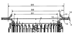
- FIG. 2 is an enlarged partial sectional view in the vicinity of an air inlet of the centrifugal multiblade fan shown in FIG. 1.
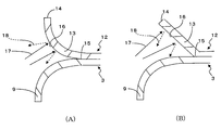
- FIG. 3 is an enlarged partial cross-sectional view in the vicinity of the inner peripheral surface of the opening of the centrifugal multiblade blower shown in FIG. 1,
- FIG. 3A is an example in which the opening is formed in a bell mouth shape, and
- FIG. The examples in which the portions are formed in a substantially truncated cone shape are shown.
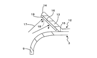
- FIG. 3 (B) it is the fragmentary sectional view which illustrated the case where the porous sheet material was stuck by the opening part inner peripheral surface.
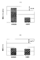
- FIG. 5A is a characteristic diagram comparing the performance of the prior art and the present invention.
- FIG. 5A shows a comparison of noise levels
- FIG. 5B shows a comparison of air flow.
- FIG. 1 is a longitudinal sectional view of the entire centrifugal multiblade fan 1
- FIG. 2 is a centrifugal multiblade fan.
- 1 is an enlarged partial cross-sectional view in the vicinity of one air inlet 9.
- the centrifugal multiblade fan 1 includes a centrifugal multiblade fan 2 and a scroll-type casing 3 in which the centrifugal multiblade fan 2 is accommodated.
- the centrifugal multiblade fan 2 includes a cone portion 4 having a substantially conical shape, and a blade 5 in which a large number of cylindrical portions are arranged on the outer peripheral portion of the cone portion 4 and one end portion is connected to the outer peripheral edge portion of the cone portion 4. It has.
- a motor 6 is accommodated inside the cone portion 4, and a rotating shaft 7 of the motor 6 is fitted in a boss hole 8 formed in a central portion of the cone portion 4. When the motor 6 is driven, the rotational driving force is transmitted to the centrifugal multiblade fan 2 via the rotating shaft 7, and the centrifugal multiblade fan 2 rotates in the circumferential direction.
- the casing 3 is formed in an air suction port 9 opened at a portion facing the top side of the cone portion 4 in FIG. 1 and an outer peripheral portion of the centrifugal multiblade fan 2, and an external heat exchanger unit or the like. And a scroll type air passage 10 provided with an air discharge portion 11 communicating with (not shown).
- the air sucked from the axial direction of the centrifugal multiblade fan 2 through the air suction port 9 passes through the gap between the blades 5 arranged in the circumferential direction along with the rotation of the centrifugal multiblade fan 2, and the diameter of the fan 2.
- the dynamic pressure obtained by the centrifugal multiblade fan 2 is converted into a static pressure in the air passage 10 and then sent out to the heat exchanger unit or the like via the air discharge section 11.
- a noise reduction member 12 having an opening 13 that opens in the upstream direction of the intake air flow is attached to the outside of the air intake port 9.
- the diameter (D2) at the upstream end 14 of the intake air flow of the opening 13 is formed larger than the diameter (D1) of the air intake 9, so that the silencing member 12 hardly inhibits the intake air flow.
- the flow rate of the intake air and the blowing performance of the multiblade blower 1 are maintained at the same high level as in the prior art.
- the diameter (D3) of the contact portion 15 that contacts the periphery of the air suction port 9 is formed to be larger than the diameter (D2) in the intake air flow upstream end portion 14.
- the diameter of the portion 13 decreases as it becomes upstream of the intake air flow, and the inner surface 16 of the opening 13 is directed in the downstream direction of the intake air flow, that is, in the direction of the centrifugal multiblade fan 2 (internal direction of the apparatus). Therefore, a part of the noise generated by the rotation of the centrifugal multiblade fan 2 is reflected toward the centrifugal multiblade fan 2 by the inner surface 16 of the opening 13 and is prevented from being released to the outside of the air inlet 9. As a result, the noise reduction of the centrifugal multiblade fan 1 is achieved.
- the present invention can be realized substantially only by adding the silencing member 12, and therefore can be easily applied to an existing centrifugal multiblade fan.
- the increase in cost and the impact on the weight of the centrifugal multiblade fan is minimized.
- the muffling member 12 in the present embodiment is bonded to the outside of the casing 3 as a member different from the casing 3, but the present invention is not limited only to the above configuration.
- the muffling member 12 may be attached to the casing 3 by fastening, or may be configured as a member formed integrally with the casing 3.
- FIG. 3 shows an enlarged partial cross-sectional view in the vicinity of the silencing member 12 of the centrifugal multiblade fan 1 shown in FIG. 1, and FIG. 3 (A) shows an example in which the silencing member 12 is formed in a bell mouth shape.
- FIG. 3B shows an example in which the sound deadening member 12 is formed in a substantially truncated cone shape.
- a part of the noise sound wave 17 generated by the rotation of the centrifugal multiblade fan 2 is reflected by the inner surface 16 of the opening 13 to become a reflected wave 18. Due to energy loss when colliding with the inner surface 16, the reflected wave 18 has a lower sound level than the original sound wave 17.
- the reflected wave 18 is reflected toward the centrifugal multiblade fan 2 and leaks outside the opening 13. There is nothing. Therefore, noise diffusion to the outside of the opening 13 is prevented by the muffling member 12, and noise reduction is achieved.
- FIG. 4 shows an example in which the porous sheet material 19 is attached to the inner surface 16 of the opening 13 in FIG.
- the porous sheet material 19 most of the sound wave 17 that has collided with the porous sheet material 19 is absorbed, and the reflected wave 18 reflected by the porous sheet material 19 does not exist at all or is very small even if it exists.
- the surface of the porous sheet material 19 adhered to the inner surface 16 faces the direction of the centrifugal multiblade fan 2, the reflected wave 18 leaks to the outside of the opening 13 as in the case of FIG. And noise reduction is more effectively achieved.
- part to which the porous sheet material 19 is affixed is not limited only to the inner surface 16 of the opening part 13, For example, even if it affixes on the inner peripheral surface of the air inlet 9, ie, the surface of the casing 3. Good.
- FIG. 5 shows the result of comparing the measured values of the noise level and the blowing performance in the embodiment shown in FIG. 1 with the centrifugal multiblade fan in the prior art.
- the performance of a centrifugal multiblade fan according to the prior art is measured, and then a sound deadening member is attached to the air inlet of the same centrifugal multiblade fan.
- the performance of the wing blower was measured.
- the diameter (D1) of the air suction port in the centrifugal multiblade fan used for the measurement is 96 mm, and the silencer attached to the outside of the air suction port is the diameter at the upstream end of the suction air flow of the opening.
- the present invention can be applied to a centrifugal multiblade fan for all uses, and is particularly suitable as a centrifugal multiblade fan for a vehicle air conditioner in which noise is severely required and the noise spreads toward the passenger cabin or crew cabin. It is a thing.
Landscapes
- Engineering & Computer Science (AREA)
- Mechanical Engineering (AREA)
- General Engineering & Computer Science (AREA)
- Structures Of Non-Positive Displacement Pumps (AREA)
Abstract
【課題】騒音を効果的に低減でき、且つ、送風性能が従来技術とほぼ同様の高い水準に維持された遠心式多翼送風機を提供する。 【解決手段】回転軸周りに複数のブレードを有する遠心式多翼ファンと、遠心式多翼ファンが収納されるスクロールケーシングを有し、スクロールケーシングに開口された空気吸入口から吸い込まれた空気をブレード間における径方向内側から吸入し径方向外側に吐出する遠心式多翼送風機において、スクロールケーシングに開口された空気吸入口の開口端外側に、空気吸入口の周囲に当接し吸入空気流上流方向へ開口する開口部を有する消音部材が付設されており、消音部材の開口部においては、吸入空気流上流側端部における口径が空気吸入口の口径よりも大きく、空気吸入口の周囲への当接部における口径が吸入空気流上流側端部における口径よりも大きいことを特徴とする遠心式多翼送風機。
Description
本発明は、遠心式多翼送風機に関し、とくに、騒音を効果的に低減でき、且つ、送風性能が従来技術とほぼ同様の高い水準に維持された遠心式多翼送風機に関する。
従来より、遠心式多翼送風機において、ファン回転時の騒音を低減する方法が各種提案されている。例えば、特許文献1には、吸入口と同一内径を有する円筒形の騒音低減部材を吸入口に設けることにより、騒音の低減を実現したスクロール型遠心送風機が開示されている。
実開昭59-175698号公報
しかしながら、特許文献1に開示された方法においては、騒音低減部材の内径が吸入口と同一の大きさであるため、吸入口外縁部より径方向内側に向かって吸入される吸入空気流が騒音低減部材によって大きく阻害されてしまい、吸入空気量が減少し、遠心送風機の送風性能が低下するおそれがある。また、騒音低減部材が円筒形であることから、遠心ファンの回転による騒音が騒音低減部材の内周面に反射されて遠心送風機外へ漏れてしまい、騒音の効果的な低減が難しくなるという懸念もある。
そこで本発明の課題は、タンク部の小型化および軽量化、ひいては熱交換器全体の小型化および軽量化の要請に対応しつつ、各熱交換チューブにほぼ均等に熱媒体を流通させることが可能な、熱媒体の流動性に優れた熱交換器を提供することにある。
上記課題を解決するために、本発明に係る遠心式多翼送風機は、回転軸周りに複数のブレードを有する遠心式多翼ファンと、該遠心式多翼ファンが収納されるスクロールケーシングを有し、該スクロールケーシングに開口された空気吸入口から吸い込まれた空気を前記ブレード間における径方向内側から吸入し径方向外側に吐出する遠心式多翼送風機において、前記スクロールケーシングに開口された空気吸入口の開口端外側に、該空気吸入口の周囲に当接し吸入空気流上流方向へ開口する開口部を有する消音部材が付設されており、該消音部材の開口部においては、吸入空気流上流側端部における口径が前記空気吸入口の口径よりも大きく、前記空気吸入口の周囲への当接部における口径が前記吸入空気流上流側端部における口径よりも大きいことを特徴とするものからなる。
このような構成においては、空気吸入口の開口端外側に消音部材が付設されているので、空気吸入時において遠心式多翼ファンから発生する騒音の一部が、消音部材により空気吸入口内側方向へ反射されるが、消音部材の開口部の口径は、空気吸入口の周囲への当接部においては上記吸入空気流上流側端部の口径よりも大きいので、消音部材の騒音反射面はテーパ状になって空気吸入口の装置内部側に向くことになり、空気吸入口の外部へ放出される騒音の低減が効率よく達成される。また、消音部材の開口部の口径は、吸入空気流上流側端部においては空気吸入口の口径よりも大きいので、消音部材の内面は全範囲にわたって空気吸入口よりも大口径となるから、吸入空気流が消音部材により阻害されることはほとんどなく、吸入空気の流量および遠心式多翼送風機の送風性能は、従来技術における消音部材を有しない遠心式多翼送風機とほぼ同様の高い水準に維持される。
また、とくに限定されないが、上記消音部材の開口部内面には多孔質シート材が貼着されていることが好ましい。このような構成においては、遠心式多翼ファンから発生する騒音の一部が多孔質シート材により吸収されるため、騒音の低減がより効果的に達成される。
本発明に係る消音部材の形状は、空気吸入口を通しての空気吸入流が実質的にほとんど阻害されない形状であればとくに限定されない。例えば、消音部材の開口部は、ベルマウス状に形成されていてもよいし、略円錐台状に形成されていてもよい。
本発明に係る遠心式多翼送風機は、とくに限定されないが、例えば、騒音の低減が厳しく要求される、車両空調装置用遠心式多翼送風機として用いられて好適なものである。
このように、本発明に係る遠心式多翼送風機によれば、空気吸入口の口径よりも大きい口径を有する消音部材により騒音が装置内部側に向けて反射されるので、騒音の低減が効果的に達成され、しかも、送風性能は従来技術とほぼ同様の高い水準に維持される。
以下に、本発明の望ましい実施の形態を、図面を参照して説明する。 図1および図2は、本発明の一実施態様に係る遠心式多翼送風機1を示しており、図1は遠心式多翼送風機1全体の縦断面図を、図2は遠心式多翼送風機1の空気吸入口9近傍における拡大部分断面図を示している。遠心式多翼送風機1は、遠心式多翼ファン2、および遠心式多翼ファン2が収容されるスクロール型のケーシング3からなる。遠心式多翼ファン2は、略円錐形状をなすコーン部4と、コーン部4の外周部に円筒状に多数列設され、一端部分がコーン部4の外周縁部分と連結されたブレード5とを備えている。コーン部4の内側にはモータ6が収納されており、モータ6の回転軸7は、コーン部4の中央部分に穿設されたボス孔8に嵌合されている。モータ6が駆動すると、その回転駆動力は回転軸7を介して遠心式多翼ファン2に伝達され、遠心式多翼ファン2は周方向に回転する。
ケーシング3は、上記コーン部4の図1における頂部側と対面する部位に開口された空気吸入口9と、遠心式多翼ファン2の外周部に形成されており、外部の熱交換器ユニット等(図示略)へと連通する空気吐出部11が設けられたスクロール型の空気通路10と、を備えている。空気吸入口9を経由して遠心式多翼ファン2の軸方向から吸入された空気は、遠心式多翼ファン2の回転に伴い周方向に複数配列されたブレード5の隙間からファン2の径方向外側へと流出し、遠心式多翼ファン2で得た動圧を空気通路10内で静圧に変換された後、空気吐出部11を経由して熱交換器ユニット等へ送出される。
空気吸入口9の外側には、吸入空気流上流方向へ開口する開口部13を有する消音部材12が付設されている。開口部13の吸入空気流上流側端部14における口径(D2)は空気吸入口9の口径(D1)よりも大きく形成されており、そのため、消音部材12は吸入空気流を阻害することはほとんどなく、吸入空気の流量、および多翼送風機1の送風性能は従来技術とほぼ同様の高い水準に維持される。また、開口部13において、空気吸入口9の周囲に当接する当接部15の口径(D3)は、吸入空気流上流側端部14における口径(D2)よりも大きく形成されているため、開口部13の口径は吸入空気流上流側になるほど小さくなり、開口部13の内面16は、吸入空気流下流方向、すなわち遠心式多翼ファン2の方向(装置の内部方向)に向けられる。したがって、遠心式多翼ファン2の回転により発生した騒音は、その一部が開口部13の内面16により遠心式多翼ファン2方向へ反射されて空気吸入口9外への放出が防止されることとなり、遠心式多翼送風機1の騒音の低減が達成される。
図1および図2に示されるように、本発明は、実質的に消音部材12の追加のみで実現可能であるため、既存の遠心式多翼送風機へ容易に適用可能であり、部品コストや組立コストの増加、および遠心式多翼送風機の重量への影響は最小限に抑えられる。
また、本実施態様における消音部材12は、ケーシング3とは異なる部材としてケーシング3の外側に接着されているが、本発明は上記の構成のみに限定されるものではない。例えば、消音部材12は、締結によりケーシング3に付設されていてもよいし、ケーシング3に一体的に成型された部材として構成されていてもよい。
図3は、図1に示した遠心式多翼送風機1の消音部材12近傍における拡大部分断面図を示しており、図3(A)は消音部材12がベルマウス状に形成された例を、図3(B)は消音部材12が略円錐台状に形成された例を、それぞれ示している。図3において、遠心式多翼ファン2の回転により発生した騒音の音波17の一部は、開口部13の内面16により反射されて反射波18となる。内面16へ衝突する際のエネルギー損失により、反射波18は元の音波17よりも音のレベルが小さくなる。また、上述の如く、開口部13の内面16は遠心式多翼ファン2の方向へ向いているので、反射波18は遠心式多翼ファン2の方向へ反射され、開口部13の外部へ漏れることがない。したがって、開口部13の外部への騒音の拡散が消音部材12により防止され、騒音の低減が達成される。
図4は、図3(B)において、開口部13の内面16に多孔質シート材19が貼着された例を示している。図4において、多孔質シート材19に衝突した音波17は大部分が吸収されてしまい、多孔質シート材19により反射される反射波18は全く存在しないか、存在したとしてもごく僅かとなる。また、内面16に貼着された多孔質シート材19の表面は遠心式多翼ファン2の方向へ向いているので、図3の場合と同様、反射波18は開口部13の外部へ漏れることがなく、騒音の低減がより効果的に達成される。なお、多孔質シート材19が貼着される部位は開口部13の内面16のみに限定されず、例えば、空気吸入口9の内周面、すなわち、ケーシング3の表面に貼着されていてもよい。
図1に示した実施態様における騒音レベルおよび送風性能の実測値を、従来技術における遠心式多翼送風機と比較した結果を図5に示す。図5の測定においては、まず、従来技術による遠心式多翼送風機の性能が測定された後、同一の遠心式多翼送風機の空気吸入口に消音部材が取り付けられ、本発明に係る遠心式多翼送風機の性能が測定された。測定に用いられた遠心式多翼送風機における空気吸入口の口径(D1)は96mmであり、空気吸入口の外側に取り付けられた消音部材としては、開口部の吸入空気流上流側端部における口径(D2)が100mm、開口部における曲率半径が12.8mmであるベルマウス形状のものが用いられた。図5に示された測定結果においては、本発明の適用により、送風性能を従来技術とほぼ同様の高い水準に維持しつつ(図5(B))、1.2dBの騒音レベル低減が達成されている(図5(A))。
本発明は、あらゆる用途における遠心式多翼送風機に適用可能であり、とくに、騒音の低減が厳しく要求される、客室または乗務員室方向へ騒音が波及する車両空調装置用遠心式多翼送風機として好適なものである。
1 遠心式多翼送風機
2 遠心式多翼ファン
3 ケーシング
4 コーン部
5 ブレード
6 モータ
7 回転軸
8 ボス孔
9 空気吸入口
10 空気通路
11 空気吐出部
12 消音部材
13 開口部
14 吸入空気流上流側端部
15 当接部
16 内面
17 音波
18 反射波
19 多孔質シート材
2 遠心式多翼ファン
3 ケーシング
4 コーン部
5 ブレード
6 モータ
7 回転軸
8 ボス孔
9 空気吸入口
10 空気通路
11 空気吐出部
12 消音部材
13 開口部
14 吸入空気流上流側端部
15 当接部
16 内面
17 音波
18 反射波
19 多孔質シート材
Claims (5)
- 回転軸周りに複数のブレードを有する遠心式多翼ファンと、該遠心式多翼ファンが収納されるスクロールケーシングを有し、該スクロールケーシングに開口された空気吸入口から吸い込まれた空気を前記ブレード間における径方向内側から吸入し径方向外側に吐出する遠心式多翼送風機において、前記スクロールケーシングに開口された空気吸入口の開口端外側に、該空気吸入口の周囲に当接し吸入空気流上流方向へ開口する開口部を有する消音部材が付設されており、該消音部材の開口部においては、吸入空気流上流側端部における口径が前記空気吸入口の口径よりも大きく、前記空気吸入口の周囲への当接部における口径が前記吸入空気流上流側端部における口径よりも大きいことを特徴とする遠心式多翼送風機。
- 前記消音部材の開口部内面に多孔質シート材が貼着されている、請求項1に記載の遠心式多翼送風機。
- 前記消音部材の開口部がベルマウス状に形成されている、請求項1または2に記載の遠心式多翼送風機。
- 前記消音部材の開口部が略円錐台状に形成されている、請求項1または2に記載の遠心式多翼送風機。
- 車両用空調装置内に設けられる、請求項1~4のいずれかに記載の遠心式多翼送風機。
Priority Applications (1)
| Application Number | Priority Date | Filing Date | Title |
|---|---|---|---|
| PCT/JP2010/002290 WO2011121642A1 (ja) | 2010-03-30 | 2010-03-30 | 遠心式多翼送風機 |
Applications Claiming Priority (1)
| Application Number | Priority Date | Filing Date | Title |
|---|---|---|---|
| PCT/JP2010/002290 WO2011121642A1 (ja) | 2010-03-30 | 2010-03-30 | 遠心式多翼送風機 |
Publications (1)
| Publication Number | Publication Date |
|---|---|
| WO2011121642A1 true WO2011121642A1 (ja) | 2011-10-06 |
Family
ID=44711440
Family Applications (1)
| Application Number | Title | Priority Date | Filing Date |
|---|---|---|---|
| PCT/JP2010/002290 Ceased WO2011121642A1 (ja) | 2010-03-30 | 2010-03-30 | 遠心式多翼送風機 |
Country Status (1)
| Country | Link |
|---|---|
| WO (1) | WO2011121642A1 (ja) |
Cited By (2)
| Publication number | Priority date | Publication date | Assignee | Title |
|---|---|---|---|---|
| CN109247023A (zh) * | 2016-05-20 | 2019-01-18 | 三菱电机株式会社 | 离心送风机、空气调节装置以及制冷循环装置 |
| CN111219363A (zh) * | 2018-11-26 | 2020-06-02 | 建准电机工业股份有限公司 | 风扇壳体与扇轮组合结构及其风扇壳体 |
Citations (3)
| Publication number | Priority date | Publication date | Assignee | Title |
|---|---|---|---|---|
| JPH07305696A (ja) * | 1994-05-10 | 1995-11-21 | Daikin Ind Ltd | 遠心送風機 |
| JP2536854Y2 (ja) * | 1990-07-20 | 1997-05-28 | 日本鋼管ライトスチール株式会社 | 2重床用吹出しフアン付きパネル |
| JP2005127309A (ja) * | 2003-10-22 | 2005-05-19 | Samsung Electronics Co Ltd | 送風装置及びこれを備えた空気調和機 |
-
2010
- 2010-03-30 WO PCT/JP2010/002290 patent/WO2011121642A1/ja not_active Ceased
Patent Citations (3)
| Publication number | Priority date | Publication date | Assignee | Title |
|---|---|---|---|---|
| JP2536854Y2 (ja) * | 1990-07-20 | 1997-05-28 | 日本鋼管ライトスチール株式会社 | 2重床用吹出しフアン付きパネル |
| JPH07305696A (ja) * | 1994-05-10 | 1995-11-21 | Daikin Ind Ltd | 遠心送風機 |
| JP2005127309A (ja) * | 2003-10-22 | 2005-05-19 | Samsung Electronics Co Ltd | 送風装置及びこれを備えた空気調和機 |
Cited By (2)
| Publication number | Priority date | Publication date | Assignee | Title |
|---|---|---|---|---|
| CN109247023A (zh) * | 2016-05-20 | 2019-01-18 | 三菱电机株式会社 | 离心送风机、空气调节装置以及制冷循环装置 |
| CN111219363A (zh) * | 2018-11-26 | 2020-06-02 | 建准电机工业股份有限公司 | 风扇壳体与扇轮组合结构及其风扇壳体 |
Similar Documents
| Publication | Publication Date | Title |
|---|---|---|
| CN107559223B (zh) | 一种消声高效离心风机 | |
| JP2003120589A (ja) | ラジエータファンおよびこれを用いたエンジン冷却装置 | |
| JP2008223741A (ja) | 遠心送風機 | |
| JP3969354B2 (ja) | 遠心ファンおよびその用途 | |
| JP2012140884A (ja) | 多翼送風機 | |
| CN101072952B (zh) | 风扇组件 | |
| JP5309516B2 (ja) | 遠心送風機 | |
| CN210196089U (zh) | 一种静音鼓风装置 | |
| JPH102299A (ja) | 遠心送風機 | |
| JP5164801B2 (ja) | 遠心式多翼送風機 | |
| CN110345110B (zh) | 消音装置及应用该消音装置的换气扇 | |
| WO2011121642A1 (ja) | 遠心式多翼送風機 | |
| CN106194797A (zh) | 汽车空调降噪风机总成 | |
| JP2012107538A (ja) | 軸流ファンまたは斜流ファンおよびこれを有する室外ユニットを搭載した空気調和機 | |
| JP2012021431A (ja) | スクロール付遠心送風機 | |
| JPH07305696A (ja) | 遠心送風機 | |
| JP2002201944A (ja) | 軸流ファン | |
| JP2010236371A (ja) | 軸流送風機、空気調和機及び換気扇 | |
| JP4807208B2 (ja) | 多翼送風機 | |
| JP2014139412A (ja) | 多翼遠心ファン及びこれを備えた多翼遠心送風機 | |
| JPWO2019146015A1 (ja) | 遠心送風機 | |
| JP2002285996A (ja) | 多翼送風ファン | |
| JP2009203908A (ja) | 送風機及び該送風機を備えた空気調和機 | |
| JPH07233798A (ja) | 多翼送風機 | |
| JP2006211770A (ja) | 回転機およびその運転方法 |
Legal Events
| Date | Code | Title | Description |
|---|---|---|---|
| 121 | Ep: the epo has been informed by wipo that ep was designated in this application |
Ref document number: 10848825 Country of ref document: EP Kind code of ref document: A1 |
|
| NENP | Non-entry into the national phase |
Ref country code: DE |
|
| 122 | Ep: pct application non-entry in european phase |
Ref document number: 10848825 Country of ref document: EP Kind code of ref document: A1 |
|
| NENP | Non-entry into the national phase |
Ref country code: JP |