WO2011114476A1 - マルチコアプロセッサシステム、通知プログラム、および通知方法 - Google Patents
マルチコアプロセッサシステム、通知プログラム、および通知方法 Download PDFInfo
- Publication number
- WO2011114476A1 WO2011114476A1 PCT/JP2010/054606 JP2010054606W WO2011114476A1 WO 2011114476 A1 WO2011114476 A1 WO 2011114476A1 JP 2010054606 W JP2010054606 W JP 2010054606W WO 2011114476 A1 WO2011114476 A1 WO 2011114476A1
- Authority
- WO
- WIPO (PCT)
- Prior art keywords
- boot program
- access
- old
- cpu
- core
- Prior art date
- Legal status (The legal status is an assumption and is not a legal conclusion. Google has not performed a legal analysis and makes no representation as to the accuracy of the status listed.)
- Ceased
Links
Images






Classifications
-
- G—PHYSICS
- G06—COMPUTING OR CALCULATING; COUNTING
- G06F—ELECTRIC DIGITAL DATA PROCESSING
- G06F9/00—Arrangements for program control, e.g. control units
- G06F9/06—Arrangements for program control, e.g. control units using stored programs, i.e. using an internal store of processing equipment to receive or retain programs
- G06F9/44—Arrangements for executing specific programs
- G06F9/4401—Bootstrapping
- G06F9/4405—Initialisation of multiprocessor systems
-
- G—PHYSICS
- G06—COMPUTING OR CALCULATING; COUNTING
- G06F—ELECTRIC DIGITAL DATA PROCESSING
- G06F9/00—Arrangements for program control, e.g. control units
- G06F9/06—Arrangements for program control, e.g. control units using stored programs, i.e. using an internal store of processing equipment to receive or retain programs
- G06F9/44—Arrangements for executing specific programs
- G06F9/4401—Bootstrapping
- G06F9/4406—Loading of operating system
- G06F9/441—Multiboot arrangements, i.e. selecting an operating system to be loaded
Definitions
- the present invention relates to a multi-core processor system for updating an operating system, a notification program, and a notification method.
- the first is to prepare a standby system in addition to the main system, and perform processing in the standby system during the update of the main system (conventional technology 1) (see, for example, Patent Documents 1 and 2 below).
- the second is to operate a virtual machine and operate software including an OS on the virtual machine during the update period (prior art 2).
- the embedded system has a problem that the system scale and cost are increased.
- there is no standby system or virtual machine there is a problem that the function must be stopped during the update because the update cannot be performed.
- the present invention provides a multi-core processor system, a notification program, and a notification method capable of realizing a non-disruptive OS update while reducing the system scale and cost in order to solve the above-described problems caused by the prior art.
- the purpose is to do.
- a multi-core processor system including a multi-core processor and a storage device that stores an old boot program and a new boot program, and booted using the old boot program in the multi-core processor Detection means for detecting a core to which no process is assigned among the cores, and when a core to which the process is not assigned is detected by the detection means, the reference area is moved from the storage area of the old boot program to the new boot.
- Detection means for detecting a core to which no process is assigned among the cores, and when a core to which the process is not assigned is detected by the detection means, the reference area is moved from the storage area of the old boot program to the new boot.
- the multi-core processor system, the notification program, and the notification method have the effect that non-disruptive update of the OS can be realized while reducing the system scale and cost.
- FIG. 10 is an explanatory diagram (part 1) illustrating an example of memory access restriction by the hypervisor 121;
- FIG. 10 is an explanatory diagram (part 2) illustrating an example of memory access restriction by the hypervisor 121;
- FIG. 10 is an explanatory diagram (part 2) illustrating an example of memory access restriction by the hypervisor 121;
- FIG. 10 is an explanatory diagram (part 3) illustrating an example of memory access restriction by the hypervisor 121;
- FIG. 10 is an explanatory diagram (part 4) illustrating an example of memory access restriction by the hypervisor 121; It is explanatory drawing which shows the example by which new OS was booted by CPU # N. It is explanatory drawing which shows the example of a preparation which boots new OS by CPU # M. It is explanatory drawing which shows the example which all the processes allocated to CPU # M completed. It is explanatory drawing which shows the example by which new OS was booted with all the CPUs.
- 5 is a flowchart (part 1) illustrating an OS update procedure performed by the multi-core processor system.
- FIG. 6 is a flowchart (part 2) illustrating an OS update procedure performed by the multi-core processor system.
- 12 is a flowchart illustrating a memory access restriction processing procedure performed by the hypervisor 121.
- 12 is a flowchart (No. 3) illustrating the OS update procedure by the multi-core processor system.
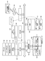
- FIG. 1 is a block diagram of a hardware configuration of the multi-core processor system according to the embodiment.
- a multi-core processor system 100 includes a CPU (Central Processing Unit) #M, a CPU #N, an arbitration circuit 102, a shared memory 103, a storage 104, and an I / F (InterFace) 105. ing. Each component is connected by a bus 101.
- CPU Central Processing Unit
- CPU #N Central Processing Unit
- arbitration circuit 102 shared memory
- shared memory 103 shared memory
- storage 104 shared memory
- I / F InterFace
- a multi-core processor is a processor equipped with a plurality of cores. If a plurality of cores are mounted, a single processor having a plurality of cores may be used, or a processor group in which single core processors are arranged in parallel may be used. In the present embodiment, in order to simplify the description, a processor group in which two processors of single core CPU #M and CPU #N are connected in parallel will be described as an example.
- CPU #M and CPU #N have a core, a cache, a register, and the like that can operate independently.
- the program stored in the storage 104 is mapped to the shared memory 103 by the CPU #M or CPU #N and loaded, thereby causing the CPU #M or CPU #N to execute the coded processing. .
- the arbitration circuit 102 is a circuit that performs arbitration so as not to compete even when accesses to the shared memory 103 occur simultaneously from different CPUs.
- the priority information in the arbitration circuit 102 is information indicating the priority for each CPU, and the arbitration circuit 102 arbitrates access to the shared memory 103 based on the priority information. In the present embodiment, there are two stages of whether the priority is high. High priority indicates that the priority is high, and low priority indicates that the priority is not high.
- the shared memory 103 is a memory having a CPU #M local area 110 and a CPU #N local area 111.
- the shared memory 103 includes, for example, a ROM (Read Only Memory), a RAM (Randam Access Memory), and the like.
- the RAM is used as a work area for CPU #M and CPU #N.
- the storage 104 has an MBR 108, an old boot program storage area (hereinafter referred to as “old boot program area 109”), and a user file system area.
- the storage 104 is configured by, for example, a flash ROM or a hard disk drive.
- the MBR (Master Boot Record) 108 is a head portion (sector) on the storage 104 that is first read when the CPU #M or CPU #N is activated.
- the MBR 108 records information such as how to boot which OS stored in the storage 104, and specifically stores a bootstrap loader, a partition table, and a boot signature.
- the bootstrap loader stores a startup program.
- the partition table shows a start address and an end address where the boot program is stored.
- the boot signature stores a value of 0xAA55 as an identifier. If 0xAA55 is stored in the boot signature, the MBR 108 is valid, and if 0xAA55 is not stored, the MBR 108 is invalid. .
- the boot program is a core program of the OS.
- the core part of the OS is the kernel.
- the old boot program area 109 is an area in which the old boot program is stored, and the start address and end address of the area are stored in the partition table.
- the new / old boot programs shown in the present embodiment indicate whether they are stored in the storage 104 first, or whether the version number has been updated.
- MBR 108 When CPU #M (or CPU #N) is activated, MBR 108 is first read, and the process coded in the activation program stored in the bootstrap loader is executed by CPU #M (or CPU #N). .
- the bootstrap loader reads the partition table that records the position and size of the partition, and reads the start address of the old boot program of the OS.
- the CPU #M reads the old boot program and maps the read old boot program to the shared memory 103.
- the area in the shared memory 103 of the old boot program mapped by the CPU #M is the CPU #M local area 110 described above. Then, the CPU #M starts the process coded in the mapped old boot program as the old OS (master) 122.
- the CPU #N reads the old boot program and maps the read old boot program to the shared memory 103.
- the area in the shared memory 103 of the old boot program mapped by the CPU #N is the CPU #N local area 111 described above. Then, the CPU #N starts the process coded in the mapped old boot program as the old OS (slave) 123 of the master OS.
- the I / F 105 controls an internal interface with the network 106 and controls input / output of data from an external device.
- a modem or the like can be adopted as the I / F 105.
- the I / F 105 is connected to a network 106 such as a LAN (Local Area Network), a WAN (Wide Area Network), or the Internet through a communication line, and is connected to an OS update data distribution source 107 via the network 106.
- a network 106 such as a LAN (Local Area Network), a WAN (Wide Area Network), or the Internet through a communication line, and is connected to an OS update data distribution source 107 via the network 106.
- the hypervisor 121 is a program that directly operates on hardware such as CPU # M and CPU # N, and is a program stored in a register in the hardware. Although the hypervisor 121 operates independently for each CPU, since all perform the same processing, only the hypervisor 121 is described in FIG.
- the hypervisor 121 directly refers to the registers in the CPU #M and CPU #N, reads the information in the registers in the CPU #M and CPU #N, and reads the information in the registers in the CPU #M and CPU #N. Privileged instructions that can be rewritten can be implemented.
- a reboot instruction to the CPU #M and CPU #N is also a privileged instruction of the hypervisor 121.
- the reboot instruction by the hypervisor 121 is to instruct the CPU #M or CPU #N to jump to the start address of the old boot program area 109 described in the partition table.
- the new boot program area by instructing CPU #M or CPU #N to jump to the start address of the storage area for the new boot program (hereinafter referred to as “new boot program area”), CPU #M or CPU #N starts the OS with a new boot program.
- the old OS (master) 122 and the old OS (slave) 123 are software that operates on the hypervisor 121. The meaning is different between the master / slave in the OS and the master / slave in the connection relationship between the CPUs.
- the master OS in this embodiment, the old OS (master) 122) runs a scheduler that determines process allocation, and the slave OS (in this embodiment, the old OS (slave) 123) executes the process assigned by the scheduler. To do.
- the master OS registers the process allocation result in the task table.
- the task table is a table of process information managed by a general OS.
- the boot time, memory resource, process number, name of the booted user, execution conditions (such as the version of the library serviced by the linked OS), and the path of the executable file are described. That is, the CPU #M reads the startup time and execution conditions from the task table by the old OS (master) 122, which OS (assignment) each application (process) is assigned to, and which application (process) has been executed. Can be monitored.
- the update detection application 131 is an application program that runs on the OS, and detects an update of the boot program.
- the update detection application 131 is allocated on the old OS (master) 122. Further, a main process 133 that is a GUI (Graphic User Interface) process is assigned to the old OS (master) 122.
- GUI Graphic User Interface
- the downloader 132 is an application program that runs on the OS, and downloads a boot program and a library.
- the downloader 132 may operate on any of the old OS (master) 122 and the old OS (slave) 123, but is assigned to the old OS (slave) 123 here.
- the downloader 132 downloads a new boot program from the OS update data distribution source 107 via the I / F 105, and performs static verification. Static verification is to check whether the binary data of the boot program is correct or conforms to a standard. Dynamic verification is to check whether a new boot program can be normally booted.
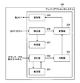
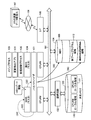
- FIG. 2 is a block diagram showing a functional configuration of the multi-core processor system 100.
- the hypervisor 121 activated in the multi-core processor system 100 includes a setting unit 201, a reception unit 202, a determination unit 203, a conversion unit 204, a notification unit 205, a detection unit 206, and a deletion unit 207. It is the composition which includes.
- the hypervisor 121 is a program including a notification program
- the CPU (#M) and the CPU (#N) cause the hypervisor 121 stored in the storage 104 or the ROM in the shared memory 103 to execute each function ( A deletion unit 207) is realized from the setting unit 201.
- the setting unit 201 sets a new boot program area based on the old boot program area 109 and a predetermined mask value.
- the receiving unit 202 receives an input of access to the old boot program area 109 related to downloading of the new boot program.
- the determining unit 203 determines whether the access received by the receiving unit 202 is a write access or a read access.
- the conversion unit 204 converts the address specified by the write access into an address specifying a new program area based on the predetermined mask value.
- the notification unit 205 When the access is a read access, the notification unit 205 notifies an access instruction to the address specified by the read access to the access source of the read access. On the other hand, when the access is a write access, the notification unit 205 notifies the access source of the write access of an access instruction to the address after conversion by the conversion unit 204. Next, processing after the new boot program is downloaded will be described.
- the detecting unit 206 detects a CPU to which no process is assigned among CPUs booted using the old boot program among the multi-core processors.
- the OS detects a core to which no process is assigned, and notifies the hypervisor 121 that a process has not been assigned to the detected core. Then, the hypervisor 121 is assumed to detect a core to which no process is assigned to accept this notification.
- the conversion unit 204 converts the reference area from the old boot program area 109 to the new boot program storage area.
- the notification unit 205 notifies the CPU that has completed the reboot instruction for designating the reference area after conversion by the conversion unit 204.
- the detection unit 206 detects a CPU in which operations of all assigned processes have been completed.
- the conversion unit 204 converts the reference area from the old boot program area 109 to the new boot program area.
- the notification unit 205 notifies the CPU that has completed the reboot instruction for designating the reference area after conversion by the conversion unit 204.
- the conversion unit 204 designates the new boot program area based on a predetermined mask value with the address that designates the old boot program area 109 stored in the master boot record of the storage device To the address to be
- the deletion unit 207 deletes the old boot program stored in the old boot program area 109 when the conversion unit 204 changes the old boot program area 109 stored in the master boot record of the storage device.
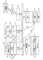
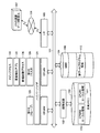
- FIG. 3 is an explanatory diagram showing a download preparation example and a download example of a new boot program.
- the update detection application 131 detects an update to the boot program via the I / F, and (1) notifies the old OS (master) 122 of the update of the boot program.
- the old OS (master) 122 receives the update of the boot program, (2) notifies the hypervisor 121 of the update of the boot program.
- the hypervisor 121 receives the update of the new boot program
- the new boot program area 112 is set based on a predetermined mask value and the area of the old boot program.
- FIG. 4 is an explanatory diagram showing an example in which the new boot program area 112 is set.
- the hypervisor 121 refers to the partition table 401 of the MBR 108 and acquires the start address and end address of the old boot program area 109.
- the hypervisor 121 calculates the start address of the new boot program area 112 by taking the logical sum of the start address of the old boot program area 109 and the mask value.
- the hypervisor 121 calculates the end address of the new boot program area 112 by taking the logical sum of the end address of the old boot program area 109 and the mask value.
- the hypervisor 121 reserves the area from the area indicated by the calculated start address of the new boot program in the storage 104 to the area indicated by the calculated end address of the new boot program as the area of the new boot program.
- the hypervisor 121 notifies the old OS (master) 122 of a download start instruction, and monitors access to the old boot program related to the downloader 132 of the new boot program and static verification.
- the old OS (master) 122 accepts the download start notification, (5) notifies the downloader 132 of the download start instruction.
- the downloader 132 receives a download start instruction, the downloader 132 downloads a new boot program from the update data distribution source 107 of the OS via the I / F 105.
- the access to the old boot program is input to the old OS (slave) 123 in order to perform write access to the old boot program.
- the old OS (slave) 123 receives access to the old boot program related to downloading of the new boot program, (7) the access is input to the hypervisor 121.
- the hypervisor 121 determines whether the access is a write access or a read access. When the hypervisor 121 determines that the access is a write access, the address indicated by the write access is converted to an address that designates the new boot program area 112 based on a predetermined mask value.
- the hypervisor 121 (8) notifies the old OS (slave) 123 of an instruction to access the converted address.
- the hypervisor 121 determines that the access is a read access, the access instruction to the address designated by the read access is notified to the old OS (slave) 123.
- the hypervisor 121 notifies the old OS (slave) 123 of an access instruction to 0x1110.
- the hypervisor 121 calculates a logical sum of 0x1110 and 0x1000 (the following formula (1)) to convert the address to the new boot program area 112. Then, the access instruction to the converted address is notified to the old OS (slave) 123.
- the hypervisor 121 notifies the old OS (slave) 123 of an access instruction to 0x0110.
- the downloader 132 executes (10) access to the address after conversion.
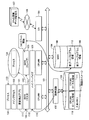
- FIG. 5 is an explanatory diagram showing an example in which CPU #N is rebooted.
- the update detection application 131 After downloading the new boot program to the new boot program area 112, the update detection application 131 notifies the old OS (master) 122 of (11) update condition information.
- the update condition information includes execution constraint, target version number, update execution CPU number, and urgency information.
- the information on the urgency level is information regarding whether or not the urgency level is high.
- the old OS (master) 122 When the old OS (master) 122 receives the update condition information, the old OS (master) 122 reads the urgency level information from the received update condition information. If the read urgency level information indicates that the urgency level is high, the old OS (master) 122 uses the task table.
- the process assigned to the update execution CPU is specified, and (12) forced migration is performed. Here, process 134 is identified.
- the process 134 assigned to the update execution CPU by the forced migration is assigned to the CPU #M.
- the update execution CPU is CPU #N.
- the update execution CPU is a CPU that reboots with a new boot program prior to other CPUs.
- the method for determining the update execution CPU is not particularly limited because at least a master OS capable of assigning a process to the old OS may be rebooted last in the old OS.
- a multi-core processor when a multi-core processor is configured by four CPUs, two CPUs from the remaining CPUs excluding the CPU that executes the processing of the master OS are set as update execution CPUs.
- the CPU that executes the process of the master OS and another CPU may be replaced with the CPU that is rebooted after the update execution CPU reboots. Further, all the remaining CPUs other than the CPU that executes the process of the master OS may be the update execution CPU.
- the old OS (master) 122 is one of the CPUs other than the CPU that operates the master OS among the multi-core processors. A CPU to which no process is assigned is detected. Since a process is assigned to CPU #N, a CPU to which no process is assigned is not detected. Next, the old OS (master) 122 prohibits dispatching to the CPU #N, and detects that the process assigned to the CPU #N is terminated.
- the boot program reference area is converted from the old boot program area 109 to the new boot program area 112, and (15) the converted reference area is designated.
- a reboot instruction is notified to the old OS (slave) 123.
- the old OS (slave) 123 receives the reboot instruction, the old OS (slave) 123 starts the reboot with reference to the new boot program (16).
- one of the update target CPUs reboots with the new OS as the master OS. Since only the CPU #N is used here, the CPU #N reboots with the new OS as the master OS.
- memory access restriction by the hypervisor 121 will be described with reference to FIGS.
- FIG. 6 is an explanatory diagram (part 1) illustrating an example of memory access restriction by the hypervisor 121.
- FIG. 6 is an explanatory diagram (part 1) illustrating an example of memory access restriction by the hypervisor 121.
- FIG. 6 a case where an access to the CPU # M local area 110 in the shared memory 103 occurs from the old OS being rebooted will be described.
- the hypervisor 121 starts the memory access restriction, the hypervisor 121 detects all accesses to the shared memory 103 from the application and access addresses.
- the hypervisor 121 (18) detects access to the CPU #M local area 110 in the shared memory 103 and the access address from the old OS being rebooted. The hypervisor 121 determines whether or not the access is from the CPU #N. Here, since the access is from the old OS (slave) 123, it is determined that the access is from the CPU #N. Subsequently, the hypervisor 121 makes a determination based on the address of the access that has detected whether or not it is an access to the local area of another CPU.
- the hypervisor 121 outputs an update failure of the old OS (slave) 123 or the downloaded new boot program is invalid.
- Is output Examples of the output format include display on a display and transmission to an external device via the I / F 105. Further, it may be stored in an area other than the local area of each CPU in the shared memory 103.
- FIG. 7 is an explanatory diagram (part 2) of an example of memory access restriction by the hypervisor 121.
- FIG. 7 (20) a case where an access to the CPU #N local area 111 in the shared memory 103 occurs from the old OS being rebooted will be described.
- the hypervisor 121 (21) detects access to the CPU #N local area 111 in the shared memory 103 from the old OS being rebooted. The hypervisor 121 determines whether or not the access is from the CPU #N. Here, since the access is from the old OS (slave) 123, it is determined that the access is from the CPU #N. Subsequently, the determination is made based on the address designated by the access in which the hypervisor 121 detects whether the access is to the local area of another CPU.
- the hypervisor 121 sets (22) priority information regarding the CPU #N in the arbitration circuit 102 to low priority. Then, the hypervisor 121 notifies an access instruction.
- the CPU #N that is booting initializes various tables, updates system files, temporarily saves and restores system files, and flushes cache data that accompanies the temporary save and restore. That is, the CPU #N that is booting has more access to the shared memory 103 than the CPU #M that is operating a normal application.
- the priority information regarding the CPU #N in the arbitration circuit 102 is set to low priority, so that memory contention (contention for memory access right) can be prevented. Then, the OS can be updated without affecting applications running on the CPU #M that is not booting.
- FIG. 8 is an explanatory diagram (part 3) of an example of memory access restriction by the hypervisor 121.
- FIG. 8 (23) a case where an access from the old OS (master) 122 to the CPU # M local area 110 in the shared memory 103 occurs will be described.
- the hypervisor 121 (24) detects access from the old OS (master) 122 to the CPU # M local area 110 in the shared memory 103. It is determined whether or not the access detected by the hypervisor 121 is an access from the CPU #N. Here, since the access is from the old OS (master) 122, it is determined that the access is not from the CPU #N. Subsequently, the determination is made based on the address indicated by the access in which the hypervisor 121 detects whether the access is to the local area of another CPU.
- the hypervisor 121 sets (25) priority information regarding the CPU # N in the arbitration circuit 102 to low priority. Then, the hypervisor 121 notifies the old OS (master) 122 of an access instruction.
- FIG. 9 is an explanatory diagram (part 4) illustrating an example of memory access restriction by the hypervisor 121.
- FIG. 9 (26) a case where an access from the old OS (master) 122 to the CPU #N local area 111 in the shared memory 103 occurs will be described.
- the hypervisor 121 (27) detects an access from the old OS (master) 122 to the CPU #N local area 111 in the shared memory 103. It is determined whether or not the access detected by the hypervisor 121 is an access from the CPU #N. Here, since the access is from the old OS (master) 122, it is determined that the access is not from the CPU #N. Subsequently, the hypervisor 121 determines based on the address indicated by the detected access whether or not it is an access to the local area of another CPU in the shared memory 103.
- the hypervisor 121 outputs (28) an access error.
- Examples of the output format include display on a display and transmission to an external device via the I / F 105. Further, it may be stored in an area other than the local area of each CPU in the shared memory 103.
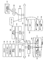
- FIG. 10 is an explanatory diagram showing an example in which the new OS is booted by the CPU #N.
- the new OS (master) 124 is booted as the master OS in CPU #N.
- a master OS exists for each new OS and old OS.
- the newly assigned new boot process 136 is scheduled and executed by the new OS (master) 124, so that there is no contention even if the old and new master OSs coexist in the multi-core processor system 100.
- the process 135 is a process assigned to the old OS (master) 122 during booting of the old OS (slave) 123.
- the hypervisor 121 releases (29) the memory access restriction and (30) restores the priority information in the arbitration circuit 102 to its original state.
- the priority information in the arbitration circuit 102 is copied and stored in the shared memory 103 immediately before the start of the memory restriction, and the priority information in the arbitration circuit 102 is changed using the copied priority information after the memory restriction is released. Restore the priority information.
- FIG. 11 is an explanatory diagram showing a preparation example for booting the new OS by the CPU #M.
- the old OS (master) 122 identifies the process assigned to the old OS (master) 122 based on the process table. Among the specified processes, processes that are dynamically linked or opened to the old boot program continue processing in the old OS (master) 122.
- the old OS (master) 122 replaces the processes (in this case, the main process 133 and the update detection application 131) that are not dynamically linked to the old boot program among the specified processes with the new OS (master) 124. Migrate to
- FIG. 12 is an explanatory diagram illustrating an example in which all processes assigned to the CPU #M are completed.
- the process of the process assigned to the old OS (master) 122 is completed. That is, the process assigned to the old OS (master) 122 by the old OS (master) 122 is not specified. Then, (32) the old OS (master) 122 notifies the hypervisor 121 that all processes assigned to the old OS (master) 122 have been completed.
- the hypervisor 121 When the hypervisor 121 receives the notification, the boot program reference area indicated by the partition table 401 stored in the MBR 108 is converted into the new boot program area 112. Then, (34) the hypervisor 121 notifies the old OS (master) 122 of a reboot instruction. Since the boot program reference area indicated by the partition table 401 has already been converted, (35) upon receiving a reboot instruction, the old OS (master) 122 starts rebooting with the new boot program. Here, the old OS (master) 122 is booted as a new OS (slave) 125. (36) The hypervisor 121 discards the old boot program.
- FIG. 13 is an explanatory diagram showing an example in which the new OS is booted by all the CPUs.
- the old OS (master) 122 is activated as the new OS (slave) 125.
- the area of the old boot program in the storage 104 is vacant.
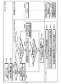
- FIG. 14 is a flowchart (part 1) illustrating the OS update procedure by the multi-core processor system 100.
- the update detection application 131 detects the update of the boot program (step S1401).
- the update detection application 131 detects the update of the boot program
- the update detection application 131 notifies the old OS (master) 122 of the update of the boot program (step S1402). ).
- the old OS (master) 122 receives the update of the boot program, it notifies the hypervisor 121 of the update of the boot program (step S1403).
- the hypervisor 121 When the hypervisor 121 receives the update of the boot program, the hypervisor 121 sets a new boot program area based on the old boot program and a predetermined mask value, and notifies the old OS (master) 122 of a download start instruction (step S1404). Then, the hypervisor 121 monitors access related to the boot program to the boot program area (step S1405). Access monitoring refers to the processing from step S1409 to step S1411.
- the old OS (master) 122 When the old OS (master) 122 receives a download start instruction from the hypervisor 121, it notifies the downloader 132 of the download start instruction (step S1406). When the downloader 132 receives the download start instruction, the downloader 132 starts download and static verification (step S1407). When the downloader 132 accesses the storage during downloading or static verification, when the OS that operates the downloader 132 inputs access to the old OS (master) 122 and receives access to the storage, the hypervisor 121 is accessed. Access is input to (step S1408).
- the hypervisor 121 determines whether the received access is a write access or a read access (step S1409).
- the hypervisor 121 determines that the access is a write access (step S1409: write access)
- the hypervisor 121 converts the address specified by the write access based on a predetermined mask value (step S1410).
- the hypervisor 121 notifies the OS that operates the downloader 132 of an access instruction to the converted address (step S1411).
- step S1409 read access
- the hypervisor 121 determines that the access is a read access (step S1409: read access)
- the hypervisor 121 notifies an access instruction to an address designated by the read access (step S1411).
- step S1411 when the OS that operates the downloader 132 accepts an access instruction, the access instruction is notified to the downloader 132 (step S1412), and when the downloader 132 accepts the access instruction, the storage is accessed (step S1413).
- An arrow between step S1407 and step S1413 indicates that download and static verification are continued according to the access result.
- FIG. 15 is a flowchart (part 2) illustrating the OS update procedure performed by the multi-core processor system 100.
- a processing procedure from the download and static verification by the hypervisor 121, the old OS (master) 122, and the downloader 132 until the reboot of the update execution CPU is completed will be described. It is assumed that the update execution CPU does not include the old OS (master) 122.
- the downloader 132 completes downloading and static verification (step S1501), it notifies update condition information (step S1502).
- step S1503 When the old OS (master) 122 receives the update condition information, the old OS (master) 122 reads the urgency level from the update condition information and determines the urgency level (step S1503). When the degree of urgency is high (step S1503: high), the old OS (master) 122 forcibly migrates the process assigned to the update execution CPU (step S1504), and proceeds to step S1507.
- step S1503 when the degree of urgency is low (step S1503: low), the old OS (master) 122 determines whether there is a CPU to which no process is assigned (step S1505). If the old OS (master) 122 determines that there is a CPU to which no process is assigned (step S1505: Yes), the CPU to which no process is assigned is set as the update execution CPU (step S1506), and the step The process moves to S1509.
- the update execution CPU is only a CPU to which no process is assigned.
- step S1505 determines that there is no CPU to which no process is assigned. If the old OS (master) 122 determines that there is no CPU to which no process is assigned (step S1505: No), the dispatch to the update execution CPU is prohibited (step S1507). Then, the old OS (master) 122 determines whether or not the process assigned to the update execution CPU has ended (step S1508). When the old OS (master) 122 determines that the process assigned to the update execution CPU has not ended (step S1508: No), the process returns to step S1508.
- step S1508 when the old OS (master) 122 determines that the process assigned to the update execution CPU has ended (step S1508: Yes), the hypervisor 121 is notified of the access restriction instruction to the shared memory and the update target CPU. (Step S1509).
- step S1510 When the hypervisor 121 receives an instruction to restrict access to the shared memory and the update target CPU, access restriction is started (step S1510). The access restriction flowchart will be described later. Then, the hypervisor 121 converts the boot program reference area into the new boot program area (step S1511).
- the hypervisor 121 notifies the OS on the update execution CPU of a reboot instruction for specifying the converted reference area (step S1512).
- the OS on the update execution CPU is an OS that causes the update execution CPU to execute processing.
- any one of the update execution CPUs is instructed to become the master OS when the new boot program is activated.
- the OS on the update execution CPU reboots when receiving the reboot instruction, and notifies the hypervisor 121 of the completion of the reboot when the reboot is completed (step S1513).
- the access restriction of the shared memory is terminated (step S1514), and the priority information in the arbitration circuit is returned to normal (step S1515). Since the priority information in the arbitration circuit is changed due to access restriction, returning the priority information to normal means returning to the priority information before the start of access restriction.
- FIG. 16 is a flowchart showing the memory access restriction processing procedure performed by the hypervisor 121.
- the hypervisor 121 detects access from the application to the shared memory (step S1601).
- the hypervisor 121 determines whether or not the access is from the update target CPU (step S1602).
- the update target CPU is being rebooted. If the hypervisor 121 determines that the access is from the update target CPU (step S1602: Yes), it determines whether the access is to the local area of another CPU (step S1603).
- step S1603 If the hypervisor 121 determines that the access is to the local area of another CPU (step S1603: Yes), it outputs an update failure (step S1604) and recovers (step S1605). On the other hand, when the hypervisor 121 determines in step S1602 that the access is not from the update target CPU (step S1602: No), it is determined whether the access is to the local area of another CPU (step S1606). When the hypervisor 121 determines that the access is to the local area of another CPU (step 1606: Yes), an access error is output (step S1607).
- step S1603 when the hypervisor 121 determines that it is not an access to the local area of another CPU (step S1603: No or step S1606: No), the priority information related to the update target CPU in the arbitration circuit is set to low priority. Setting is performed (step S1608). Then, the access instruction is notified to the access source (step S1609). The process is repeated until the hypervisor 121 receives a memory access restriction end instruction.
- FIG. 17 is a flowchart (part 3) illustrating the OS update procedure performed by the multi-core processor system 100.
- the new OS (master) 124 controls to allocate a new process to the new OS (step S1701).
- the old OS (master) 122 identifies a process already running on the old OS based on the task table (step S1702).
- the old OS (master) 122 determines whether or not there is a process already operating on the old OS (step S1703). First, when the old OS (master) 122 determines that there is an already-operated process in the old OS (step S1703: Yes), it determines whether there is an unselected already-processed process (step S1704). When the old OS (master) 122 determines that there is no unselected process already operating (step S1704: No), the process returns to step S1702. On the other hand, when the old OS (master) 122 determines that there is an unselected operation process (step S1704: Yes), an arbitrary process is selected from the unselected operation processes (step S1705).
- the old OS (master) 122 determines whether the selected process is dynamically linked or opened to the system file (step S1706). If the old OS (master) 122 determines that the system file is dynamically linked or opened (step S1706: YES), the process returns to step S1704. On the other hand, when the old OS (master) 122 determines that the system file is not dynamically linked and opened (step S1706: No), the selected process is migrated to the new OS (step S1707), and the process returns to step S1704. .
- the old OS (master) 122 determines that there is no process already operating in the old OS (step S1703: No)
- it notifies the hypervisor 121 that there is no process already operating (step S1708).
- the hypervisor 121 converts the reference area in the partition table to the new boot program area (step S1709), and notifies the old OS of a reboot instruction for specifying the converted reference area (step S1710).
- the hypervisor 121 discards the old boot program (step S1711).
- the reboot instruction for rebooting with the new boot program is notified in order from the core to which no process is assigned among the cores booted with the old boot program. Therefore, the core that has been notified of and received the reboot instruction reboots with the new boot program. As a result, since the system is rebooted immediately from the free core, the OS can be updated without stopping without stopping the process.
- the OS can be updated without stopping the running process by notifying the reboot instruction to reboot the core to which the assigned process has been completed with a new boot program.
- the capacity in the storage can be used efficiently by setting a new boot program area for downloading the new boot program after accepting the update of the new boot program.
- the address of the old boot program area in the partition table of the master boot record is converted to the address of the new boot program area.
Landscapes
- Engineering & Computer Science (AREA)
- Software Systems (AREA)
- Theoretical Computer Science (AREA)
- Computer Security & Cryptography (AREA)
- Physics & Mathematics (AREA)
- General Engineering & Computer Science (AREA)
- General Physics & Mathematics (AREA)
- Stored Programmes (AREA)
- Multi Processors (AREA)
Abstract
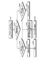
新ブートプログラムのダウンロードおよび静的ベリファイが終了し、緊急度が低い場合(ステップS1503:低)、旧OS(マスタ)(122)が、旧ブートプログラムを用いてブートしたコアのうち、プロセスが割り当てられていないコアがあるか否かを判断する(ステップS1505)。旧OS(マスタ)(122)が、プロセスが割り当てられていないコアがあると判断した場合(ステップS1505:Yes)、ハイパーバイザ(121)がブートプログラムの参照領域を旧ブートプログラム領域から新ブートプログラム領域に変換し(ステップS1511)、変換後の参照領域を指定するリブート指示をプロセスが割り当てられていないコアへ通知する(ステップS1512)。
Description
本発明は、オペレーティングシステムを更新するマルチコアプロセッサシステム、通知プログラム、および通知方法に関する。
従来の携帯型端末では、オペレーティングシステム(以下、「OS(Operating System)」と称する。)の更新に当たり、更新期間中にはアプリケーションの動作を停止させる必要があった。このため、更新期間中には、利用者はアプリケーションの動作(以下、「機能」と称する。)を利用することができないので、深夜時間帯など利用者の利用頻度が下がる時間帯に更新が行われていた。しかし、汎用計算機とは異なり、携帯型端末などの組み込みシステムは24時間365日動かし続けることを想定しており、機能を停止させなければならないことが問題となっていた。
サーバ分野においては、無停止でアップデートを行う2つの手法が提案されている。一つ目は、主系統の他に待機系統を用意し、主系統のアップデート中には待機系統で処理を行うもの(従来技術1)である(たとえば、下記特許文献1,2を参照。)。2つ目は、仮想マシンを運用し、アップデート期間中にOSを含むソフトウェアを仮想マシンで動作させること(従来技術2)である。
しかしながら、従来技術1および従来技術2の場合、組み込みシステムにおいては、システム規模や費用の増加を招くという問題があった。一方、待機系統や仮想マシンがない場合、アップデートを代行することができないため、アップデートの際に機能を停止しなければならないという問題があった。
このように、携帯型端末などの組み込みシステムは24時間365日動かし続けることを想定しており、従来では、更新期間中には、利用者は機能を利用することができず、また、機能を停止させなければならないことが問題となっていた。
本発明は、上述した従来技術による問題点を解消するため、システム規模や費用の低減化を図りつつ、OSの無停止アップデートを実現することができるマルチコアプロセッサシステム、通知プログラム、および通知方法を提供することを目的とする。
本発明の一観点によれば、マルチコアプロセッサと、旧ブートプログラムおよび新ブートプログラムを記憶する記憶装置とを備えるマルチコアプロセッサシステムであって、前記マルチコアプロセッサの中で前記旧ブートプログラムを用いてブートしたコアのうち、プロセスが割り当てられていないコアを検出する検出手段と、前記検出手段により前記プロセスが割り当てられていないコアが検出されると、参照領域を前記旧ブートプログラムの記憶領域から前記新ブートプログラムの記憶領域に変換する変換手段と、前記変換手段による変換後の参照領域を指定するリブート指示を前記割り当てられていないコアへ通知する通知手段と、を備えるマルチコアプロセッサシステムを提供する。
本マルチコアプロセッサシステム、通知プログラム、および通知方法によれば、システム規模や費用の低減化を図りつつ、OSの無停止アップデートを実現することができるという効果を奏する。
以下に添付図面を参照して、本発明にかかるマルチコアプロセッサシステム、通知プログラム、および通知方法の好適な実施の形態を詳細に説明する。
(マルチコアプロセッサシステムのハードウェア構成)
図1は、実施の形態にかかるマルチコアプロセッサシステムのハードウェア構成を示すブロック図である。図1において、マルチコアプロセッサシステム100は、CPU(Central Processing Unit)♯Mと、CPU#Nと、調停回路102と、共有メモリ103と、ストレージ104と、I/F(InterFace)105と、を備えている。また、各構成部は、バス101によってそれぞれ接続されている。
図1は、実施の形態にかかるマルチコアプロセッサシステムのハードウェア構成を示すブロック図である。図1において、マルチコアプロセッサシステム100は、CPU(Central Processing Unit)♯Mと、CPU#Nと、調停回路102と、共有メモリ103と、ストレージ104と、I/F(InterFace)105と、を備えている。また、各構成部は、バス101によってそれぞれ接続されている。
ここで、マルチコアプロセッサとは、コアが複数搭載されたプロセッサである。コアが複数搭載されていれば、複数のコアが搭載された単一のプロセッサでもよく、シングルコアのプロセッサが並列されているプロセッサ群でもよい。なお、本実施の形態では、説明を単純化するため、シングルコアのCPU#MとCPU#Nの2つのプロセッサが並列に接続されているプロセッサ群を例に挙げて説明する。
CPU#MとCPU#Nは、独立して動作可能なコアとキャッシュとレジスタなどを備えている。ストレージ104に記憶されているプログラムは、CPU#MまたはCPU#Nによって共有メモリ103にマッピングされ、ロードされることで、コーディングされている処理をCPU#MまたはCPU#Nに実行させることとなる。
調停回路102は、別々のCPUから同時に共有メモリ103へのアクセスが発生しても競合しないように調停する回路である。調停回路102内の優先度の情報は、CPUごとの優先度を示す情報であり、調停回路102は優先度の情報に基づいて共有メモリ103へのアクセスを調停する。本実施の形態では、優先度は高いか否かの2段階とする。高優先は優先度が高いことを示し、低優先は優先度が高くないことを示す。
共有メモリ103は、CPU#Mローカル領域110やCPU#Nローカル領域111を有するメモリである。共有メモリ103は、たとえば、ROM(Read Only Memory)、RAM(Randam Access Memory)などにより構成されている。たとえば、RAMは、CPU#MとCPU#Nのワークエリアとして使用される。
ストレージ104は、MBR108と、旧ブートプログラムの記憶領域(以下、「旧ブートプログラム領域109」)と、ユーザのファイルシステム領域を有している。ストレージ104は、たとえば、フラッシュROMやハードディスクドライブなどにより構成されている。
MBR(Master Boot Record)108とは、CPU#MやCPU#Nの起動時に最初に読み込まれるストレージ104上の先頭部分(セクタ)である。MBR108には、ストレージ104内に収められたどのOSをどのように起動するかなどの情報が記録され、具体的には、ブートストラップローダ、パーティションテーブル、ブートシグニチャがそれぞれ格納されている。
ブートストラップローダには、起動用のプログラムが格納されている。パーティションテーブルにはブートプログラムが格納されている開始アドレスおよび終了アドレスが示されている。ブートシグニチャには0xAA55という値が識別子として格納され、該ブートシグニチャに0xAA55が格納されていればMBR108が有効であることを示し、0xAA55が格納されていなければMBR108が無効であることを示している。
ここで、ブートプログラムとは、OSの中核部分のプログラムである。たとえば、Linuxの場合、OSの中核部分はカーネルである。旧ブートプログラム領域109は、旧ブートプログラムが記憶されている領域であり、該領域の開始アドレスから終了アドレスはパーティションテーブルに記憶されている。本実施の形態で示すブートプログラムの新・旧は、先にストレージ104に記憶されているか否か、または版数が更新されているか否かを示している。
CPU#M(またはCPU#N)を起動するとまずMBR108が読み込まれ、ブートストラップローダに格納されている起動用のプログラムにコーディングされている処理がCPU#M(またはCPU#N)に実行される。ブートストラップローダはパーティションの位置や大きさなどを記録したパーティションテーブルを読み込み、OSの旧ブートプログラムの開始アドレスを読み込む。
ここで、CPU#Mは旧ブートプログラムを読み込み、読み込んだ旧ブートプログラムを共有メモリ103にマッピングする。CPU#Mがマッピングした旧ブートプログラムの共有メモリ103内の領域が、上述のCPU#Mローカル領域110である。そして、CPU#Mが、マッピングした旧ブートプログラムにコーディングされている処理を旧OS(マスタ)122として起動する。
一方、CPU#Nは旧ブートプログラムを読み込み、読み込んだ旧ブートプログラムを共有メモリ103にマッピングする。CPU#Nがマッピングした旧ブートプログラムの共有メモリ103内の領域が、上述のCPU#Nローカル領域111である。そして、CPU#Nが、マッピングした旧ブートプログラムにコーディングされている処理をマスタOSの旧OS(スレーブ)123として起動する。
そして、I/F105は、ネットワーク106と内部のインターフェースを司り、外部装置からのデータの入出力を制御する。I/F105には、たとえばモデムなどを採用することができる。I/F105は、通信回線を通じてLAN(Local Area Network)、WAN(Wide Area Network)、インターネットなどのネットワーク106に接続され、このネットワーク106を介してOSの更新データ配信元107に接続される。
つぎに、ハイパーバイザ121は、CPU#MとCPU#Nなどのハードウェア上で直接動作するプログラムであり、該ハードウェア内のレジスタに記憶されているプログラムである。ハイパーバイザ121はCPUごとに独立して動作するが、すべて同一処理を実施するため、図1では省略してハイパーバイザ121のみ記載している。
なお、たとえば、後述する旧ブートプログラムの削除処理であれば、複数のハイパーバイザ121が一つしか存在しない旧ブートプログラムを削除しているようであるが、最も早く削除処理まで処理がたどり着いたCPUのハイパーバイザ121が削除を行う。よって、あとから他のCPUのハイパーバイザ121が削除処理を行っても破棄する旧ブートプログラムはすでに存在しないだけである。
ハイパーバイザ121は、CPU#MやCPU#N内のレジスタを直接参照したり、CPU#MやCPU#N内のレジスタの情報を読み出したり、CPU#MやCPU#N内のレジスタの情報を書き換えたりする特権命令を実施することができる。
さらに、CPU#MやCPU#Nへのリブート指示もハイパーバイザ121の特権命令である。ハイパーバイザ121によるリブート指示とは、具体的には、パーティションテーブル内に記述されている旧ブートプログラム領域109の開始アドレスにジャンプするようにCPU#MやCPU#Nへ指示することである。本実施の形態では、新ブートプログラムの記憶領域(以下、「新ブートプログラム領域」と称する。)の開始アドレスへジャンプするようにCPU#MやCPU#Nへ指示することで、CPU#MやCPU#Nは新ブートプログラムでOSを起動する。
旧OS(マスタ)122および旧OS(スレーブ)123は、ハイパーバイザ121上で動作するソフトウェアである。OSにおけるマスタ・スレーブとCPU間の接続関係におけるマスタ・スレーブとは意味が異なる。マスタOS(本実施の形態では旧OS(マスタ)122)ではプロセスの割り当てを決定するスケジューラを動かし、スレーブOS(本実施の形態では旧OS(スレーブ)123)はスケジューラにより割り当てられたプロセスを実行する。
マスタOSは、プロセスの割り当て結果をタスクテーブルに登録する。ここで、タスクテーブルは、一般的なOSで管理されているプロセス情報のテーブルである。起動時間、メモリリソース、プロセス番号、起動したユーザ名、実行条件(リンクしているOSがサービスするライブラリの版数など)、実行形式ファイルのパスなどが記載されている。すなわち、CPU#Mは、旧OS(マスタ)122によりタスクテーブルから起動時間や実行条件を読み出すことで、各アプリケーション(プロセス)がどのOSに割り当てられているか、どのアプリケーション(プロセス)が実行終了したかを監視することができる。
また、更新検出アプリ131は、OS上で動作するアプリケーションプログラムであり、ブートプログラムの更新を検出する。更新検出アプリ131は、旧OS(マスタ)122上に割り当てられている。また、GUI(Graphic User Interface)のプロセスであるメインプロセス133が旧OS(マスタ)122に割り当てられている。
ダウンローダ132は、OS上で動作するアプリケーションプログラムであり、ブートプログラムやライブラリをダウンロードする。ダウンローダ132は、旧OS(マスタ)122と旧OS(スレーブ)123のうちいずれのOS上で動作しても良いが、ここでは、旧OS(スレーブ)123に割り当てられている。
ダウンローダ132は、I/F105を介してOSの更新データ配信元107から新ブートプログラムをダウンロードし、静的ベリファイを実施する。静的ベリファイとは、ブートプログラムのバイナリデータに誤りがないか、規格に従っているかなどを検査することである。動的ベリファイとは、新ブートプログラムで正常にブートされるかを検査することである。
(マルチコアプロセッサシステム100の機能的構成)
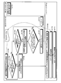
図2は、マルチコアプロセッサシステム100の機能的構成を示すブロック図である。マルチコアプロセッサシステム100で起動されているハイパーバイザ121は、設定部201と、受付部202と、判断部203と、変換部204と、通知部205と、検出部206と、削除部207と、を含む構成である。上述のようにハイパーバイザ121は通知プログラムを備えるプログラムであるため、ストレージ104または共有メモリ103内のROMに記憶されたハイパーバイザ121をCPU#MおよびCPU#Nに実行させることにより、各機能(設定部201から削除部207)を実現する。
図2は、マルチコアプロセッサシステム100の機能的構成を示すブロック図である。マルチコアプロセッサシステム100で起動されているハイパーバイザ121は、設定部201と、受付部202と、判断部203と、変換部204と、通知部205と、検出部206と、削除部207と、を含む構成である。上述のようにハイパーバイザ121は通知プログラムを備えるプログラムであるため、ストレージ104または共有メモリ103内のROMに記憶されたハイパーバイザ121をCPU#MおよびCPU#Nに実行させることにより、各機能(設定部201から削除部207)を実現する。
まず、設定部201は、新ブートプログラムの更新指示を受け付けると、旧ブートプログラム領域109と所定のマスク値に基づいて新ブートプログラム領域を設定する。
つぎに、受付部202は、設定部201により新ブートプログラム領域が設定された後、新ブートプログラムのダウンロードに関する旧ブートプログラム領域109へのアクセスの入力を受け付ける。
判断部203は、受付部202により受け付けられたアクセスがライトアクセスであるかリードアクセスであるかを判断する。
変換部204は、判断部203によりアクセスがライトアクセスであると判断された場合、ライトアクセスで指定されたアドレスを、前記所定のマスク値に基づいて新プログラム領域を指定するアドレスに変換する。
通知部205は、アクセスがリードアクセスの場合、リードアクセスで指定されたアドレスへのアクセス指示をリードアクセスのアクセス元へ通知する。一方、通知部205は、アクセスがライトアクセスの場合、変換部204による変換後のアドレスへのアクセス指示をライトアクセスのアクセス元へ通知する。つぎに、新ブートプログラムがダウンロードされた後の処理について説明する。
検出部206は、マルチコアプロセッサの中で旧ブートプログラムを用いてブートしたCPUのうち、プロセスが割り当てられていないCPUを検出する。本実施の形態では、後述するがOSはプロセスが割り当てられていないコアを検出し、ハイパーバイザ121へ検出したコアにプロセスが割り当てられていないことを通知する。そして、ハイパーバイザ121はこの通知を受け付けることをプロセスが割り当てられていないコアを検出するとしている。
変換部204は、検出部206によりプロセスが割り当てられていないCPUが検出されると、参照領域を旧ブートプログラム領域109から新ブートプログラムの記憶領域に変換する。
通知部205は、変換部204よる変換後の参照領域を指定するリブート指示を完了したCPUへ通知する通知する。
また、検出部206は、プロセスが割り当てられていないCPUが検出されない場合、割り当てられていたすべてのプロセスの動作が完了したCPUを検出する。
そして、変換部204は、検出部206により該完了したCPUが検出されると、参照領域を旧ブートプログラム領域109から新ブートプログラム領域に変換する。通知部205は、変換部204よる変換後の参照領域を指定するリブート指示を完了したCPUへ通知する通知する。
変換部204は、通知部205によりリブート指示が通知されると、記憶装置のマスターブートレコードに記憶されている旧ブートプログラム領域109を指定するアドレスを所定のマスク値に基づき新ブートプログラム領域を指定するアドレスに変換する。
削除部207は、変換部204により記憶装置のマスターブートレコードに記憶されている旧ブートプログラム領域109が変更されると、旧ブートプログラム領域109に格納されている旧ブートプログラムを削除する。
以上を踏まえて図を用いてマルチコアプロセッサシステム100の詳細な動作について説明する。
図3は、新ブートプログラムのダウンロード準備例とダウンロード例を示す説明図である。まず、更新検出アプリ131がI/Fを介してブートプログラムへの更新を検出し、(1)旧OS(マスタ)122へブートプログラムの更新を通知する。つぎに、旧OS(マスタ)122がブートプログラムの更新を受け付けると、(2)ハイパーバイザ121へブートプログラムの更新を通知する。そして、ハイパーバイザ121が新ブートプログラムの更新を受け付けると、(3)新ブートプログラム領域112を所定のマスク値と旧ブートプログラムの領域に基づいて設定する。
図4は、新ブートプログラム領域112が設定される例を示す説明図である。ここで、(3)新ブートプログラムの領域の設定について詳細例を説明する。ハイパーバイザ121はMBR108のパーティションテーブル401を参照し、旧ブートプログラム領域109の開始アドレスおよび終了アドレスを取得する。ハイパーバイザ121は旧ブートプログラム領域109の開始アドレスとマスク値との論理和を取ることにより新ブートプログラム領域112の開始アドレスを算出する。
ハイパーバイザ121は旧ブートプログラム領域109の終了アドレスとマスク値との論理和を取ることにより新ブートプログラム領域112の終了アドレスを算出する。ハイパーバイザ121は、ストレージ104内の算出した新ブートプログラムの開始アドレスが示す領域から算出した新ブートプログラムの終了アドレスが示す領域までを新ブートプログラムの領域として確保する。
図3に戻って、(4)ハイパーバイザ121が旧OS(マスタ)122へダウンロード開始指示を通知し、新ブートプログラムのダウンローダ132および静的ベリファイに関する旧ブートプログラムへのアクセスを監視する。旧OS(マスタ)122がダウンロード開始通知を受け付けると、(5)ダウンローダ132へダウンロード開始指示を通知する。そして、ダウンローダ132はダウンロード開始指示を受け付けると、I/F105を介してOSの更新データ配信元107から新ブートプログラムをダウンロードする。
そして、ダウンローダ132が新ブートプログラムをダウンロード中、旧ブートプログラムへのライトアクセスを行うために(6)旧OS(スレーブ)123へ旧ブートプログラムへのアクセスを入力する。旧OS(スレーブ)123が、新ブートプログラムのダウンロードに関する旧ブートプログラムへのアクセスを受け付けると、(7)ハイパーバイザ121へ該アクセスを入力する。
そして、ハイパーバイザ121が、新ブートプログラムのダウンロードに関する旧ブートプログラムへのアクセスを受け付けると、該アクセスがライトアクセスであるかリードアクセスであるかを判断する。ハイパーバイザ121がライトアクセスであると判断した場合、該ライトアクセスが示すアドレスを所定のマスク値に基づいて新ブートプログラム領域112を指定するアドレスに変換する。
そして、ハイパーバイザ121が、(8)変換後のアドレスへのアクセス指示を旧OS(スレーブ)123へ通知する。一方、ハイパーバイザ121がリードアクセスであると判断した場合、リードアクセスで指定されたアドレスへのアクセス指示を旧OS(スレーブ)123へ通知する。
アクセスが指定するアドレスを0x1110とし、所定のマスク値を0x1000とすする。たとえば、リードアクセスの場合、ハイパーバイザ121が0x1110へのアクセス指示を旧OS(スレーブ)123へ通知する。たとえば、ライトアクセスの場合、ハイパーバイザ121が0x1110と0x1000の論理和を算出する(下記式(1))ことで新ブートプログラム領域112を指定するアドレスに変換する。そして、変換後のアドレスへのアクセス指示を旧OS(スレーブ)123へ通知する。
ブートプログラム領域を指定するアドレス=0x1110+0x1000
=0x0110 ・・・(1)
=0x0110 ・・・(1)
ここで、「+」が論理和を示している。よって、ハイパーバイザ121が0x0110へのアクセス指示を旧OS(スレーブ)123へ通知する。
旧OS(スレーブ)123は、ハイパーバイザ121からアクセス指示を受け付けると、(9)ダウンローダ132へアクセス指示を通知する。図3では、ライトアクセスを示しているため、ダウンローダ132は、(10)変換後のアドレスへのアクセスを実行する。
図5は、CPU#Nがリブートされる例を示す説明図である。新ブートプログラム領域112への新ブートプログラムのダウンロード後、更新検出アプリ131が(11)更新条件情報を旧OS(マスタ)122へ通知する。更新条件情報は、実行制約と、対象版数と、更新実施CPU数と、緊急度の情報とを有している。緊急度の情報は緊急度が高いか否かに関する情報である。
旧OS(マスタ)122は、更新条件情報を受け付けると、受け付けた更新条件情報から緊急度の情報を読み出し、読み出した緊急度の情報が、緊急度が高いことを示す場合、タスクテーブルを用いて更新実施CPUに割り当てられているプロセスを特定し、(12)強制マイグレートする。ここでは、プロセス134が特定される。強制マイグレートにより更新実施CPUに割り当てられているプロセス134がCPU#Mに割り当てられている。
ここで、更新実施CPUをCPU#Nとする。更新実施CPUとは、他のCPUに先だって新ブートプログラムでリブートするCPUである。更新実施CPUの決定方法については、少なくとも旧OSへのプロセスの割り当てが可能なマスタOSが旧OSの中で最後にリブートされればよいため、特に限定しない。
たとえば、4つのCPUによりマルチコアプロセッサが構成されている場合、マスタOSの処理を実行するCPUを除く残余のCPUから2つのCPUを更新実施CPUとする。そして、マスタOSの処理を実行するCPUともう一つのCPUを更新実施CPUがリブート後にリブートするCPUとしてもよい。また、マスタOSの処理を実行するCPUを除く残余のCPUをすべて更新実施CPUとしてもよい。
また、読み出した緊急度の情報が、緊急度が高くない(緊急度が低い)ことを示す場合、旧OS(マスタ)122が、マルチコアプロセッサのうちマスタOSを動作するCPUを除くCPUからいずれのプロセスも割り当てられていないCPUを検出する。CPU#Nには、プロセスが割り当てられているため、いずれのプロセスも割り当てられていないCPUは検出されない。つぎに、旧OS(マスタ)122が、CPU#Nへのディスパッチを禁止し、CPU#Nに割り当てられているプロセスが終了するのを検出する。
そして、強制マイグレートまたはプロセスの終了によってCPU#Nに割り当てられていたプロセスが無くなると、(13)旧OS(マスタ)122がCPU#Nに割り当てられていたプロセスが完了したこと(または、更新実施CPUでもよい。)およびメモリアクセス制限指示をハイパーバイザ121へ通知する。ハイパーバイザ121が該通知を受け付けると、(14)共有メモリ103のアクセス制限を開始する。ハイパーバイザ121が共有メモリ103のアクセス制限を開始すると、たとえば、各OSやアプリケーションはハイパーバイザ121からのアクセス指示を受け付けるまで共有メモリ103へアクセスできないこととする。
そして、ハイパーバイザ121が、共有メモリ103のアクセス制限を開始した後、ブートプログラムの参照領域を旧ブートプログラム領域109から新ブートプログラム領域112へ変換し、(15)変換後の参照領域を指定するリブート指示を旧OS(スレーブ)123へ通知する。旧OS(スレーブ)123は、リブート指示を受け付けると、(16)新ブートプログラムを参照してリブートを開始する。また、更新対象CPUのうち一つのCPUが新OSをマスタOSとしてリブートする。ここでは、CPU#Nのみであるため、CPU#Nが新OSをマスタOSとしてリブートする。つぎに、ハイパーバイザ121によるメモリアクセス制限について図6から図9を用いて説明する。
図6は、ハイパーバイザ121によるメモリアクセス制限例を示す説明図(その1)である。図では、(17)リブート中の旧OSから共有メモリ103内のCPU#Mローカル領域110へのアクセスが発生した場合について説明する。ハイパーバイザ121は、メモリアクセス制限を開始すると、アプリケーションから共有メモリ103へのアクセスおよびアクセスのアドレスをすべて検出する。
ハイパーバイザ121が(18)リブート中の旧OSから共有メモリ103内のCPU#Mローカル領域110へのアクセスとアクセスのアドレスを検出する。ハイパーバイザ121がCPU#Nからのアクセスか否かを判断し、ここでは、旧OS(スレーブ)123からのアクセスであるためCPU#Nからのアクセスであると判断される。つづいて、ハイパーバイザ121が他のCPUのローカル領域へのアクセスか否かを検出したアクセスのアドレスに基づいて判断する。
ここでは、検出されたアクセスがCPU#Mローカル領域110へのアクセスであると判断され、(19)ハイパーバイザ121が旧OS(スレーブ)123の更新失敗を出力、またはダウンロードした新ブートプログラムが不正であることを出力する。出力形式としては、たとえば、ディスプレイへの表示、I/F105による外部装置への送信がある。また、共有メモリ103内の各CPUのローカル領域を除く領域などに記憶することとしてもよい。
ブート中であるCPU#NからCPU#MのワークエリアであるCPU#Mローカル領域110へのアクセスは正常なブートプログラムであれば発生しない。したがって、(17)~(19)により異常であるブートプログラムで更新するのを防止することができる。
図7は、ハイパーバイザ121によるメモリアクセス制限例を示す説明図(その2)である。図7では、(20)リブート中の旧OSから共有メモリ103内のCPU#Nローカル領域111へのアクセスが発生した場合について説明する。
ハイパーバイザ121が(21)リブート中の旧OSから共有メモリ103内のCPU#Nローカル領域111へのアクセスを検出する。ハイパーバイザ121がCPU#Nからのアクセスか否かを判断し、ここでは、旧OS(スレーブ)123からのアクセスであるためCPU#Nからのアクセスであると判断される。つづいて、ハイパーバイザ121が他のCPUのローカル領域へのアクセスか否かを検出したアクセスが指定するアドレスに基づいて判断する。
ここでは、検出されたアクセスがCPU#Nローカル領域111へのアクセスであると判断され、ハイパーバイザ121が(22)調停回路102内のCPU#Nに関する優先度の情報を低優先に設定する。そして、ハイパーバイザ121がアクセス指示を通知する。
ブート中であるCPU#Nは、各種テーブルの初期化やシステムファイルの更新、システムファイルの一時退避・復元、該一時退避・復元にともなうキャッシュデータのフラッシュなどを行う。すなわち、ブート中であるCPU#Nは、通常のアプリケーションを動作中であるCPU#Mと比較して共有メモリ103へのアクセスが多い。
上述のように調停回路102内のCPU#Nに関する優先度の情報が低優先に設定されることで、メモリコンテンション(メモリアクセス権の争奪)を防止することができる。そして、ブート中でないCPU#Mで動作しているアプリケーションに影響を与えることなくOSを更新できる。
図8は、ハイパーバイザ121によるメモリアクセス制限例を示す説明図(その3)である。図8では、(23)旧OS(マスタ)122から共有メモリ103内のCPU#Mローカル領域110へのアクセスが発生した場合について説明する。
ハイパーバイザ121が(24)旧OS(マスタ)122から共有メモリ103内のCPU#Mローカル領域110へのアクセスを検出する。ハイパーバイザ121が検出したアクセスがCPU#Nからのアクセスか否かを判断し、ここでは、旧OS(マスタ)122からのアクセスであるためCPU#Nからのアクセスでないと判断される。つづいて、ハイパーバイザ121が他のCPUのローカル領域へのアクセスか否かを検出したアクセスが示すアドレスに基づいて判断する。
ここでは、検出されたアクセスがCPU#Mローカル領域110へのアクセスであると判断され、ハイパーバイザ121が(25)調停回路102内のCPU#Nに関する優先度の情報を低優先に設定する。そして、ハイパーバイザ121が旧OS(マスタ)122へアクセス指示を通知する。
図9は、ハイパーバイザ121によるメモリアクセス制限例を示す説明図(その4)である。図9では、(26)旧OS(マスタ)122から共有メモリ103内のCPU#Nローカル領域111へのアクセスが発生した場合について説明する。
ハイパーバイザ121が(27)旧OS(マスタ)122から共有メモリ103内のCPU#Nローカル領域111へのアクセスを検出する。ハイパーバイザ121が検出したアクセスがCPU#Nからのアクセスか否かを判断し、ここでは、旧OS(マスタ)122からのアクセスであるためCPU#Nからのアクセスでないと判断される。つづいて、ハイパーバイザ121が共有メモリ103内の他のCPUのローカル領域へのアクセスか否かを検出したアクセスが示すアドレスに基づいて判断する。
ここでは、検出されたアクセスがCPU#Nローカル領域111へのアクセスであると判断され、ハイパーバイザ121が(28)アクセスエラーを出力する。出力形式としては、たとえば、ディスプレイへの表示、I/F105による外部装置への送信がある。また、共有メモリ103内の各CPUのローカル領域を除く領域などに記憶することとしてもよい。
図10は、CPU#Nで新OSがブートされた例を示す説明図である。図10では、CPU#Nで新OS(マスタ)124がマスタOSとしてブートされている。ここで、新OSと旧OSごとにマスタOSが存在することとなる。新たに割り当てられる新規起動プロセス136は新OS(マスタ)124によりスケジュールされて実行されるため、マルチコアプロセッサシステム100において新旧のマスタOSが共存していても競合することはない。また、プロセス135は旧OS(スレーブ)123がブート中に旧OS(マスタ)122に割り当てられたプロセスである。
そして、ハイパーバイザ121が、CPU#Nで新OS(マスタ)124がブートされると、(29)メモリアクセス制限を解除し、(30)調停回路102内の優先度の情報を元に戻す。調停回路102内の優先度の情報は、たとえば、メモリ制限開始直前に共有メモリ103内に複製して記憶しておき、メモリ制限解除後に複製した優先度の情報を用いて調停回路102内の変更された優先度の情報を復元する。
図11は、CPU#Mで新OSをブートさせる準備例を示す説明図である。旧OS(マスタ)122が、旧OS(マスタ)122に割り当てられているプロセスをプロセステーブルに基づいて特定する。特定したプロセスのうち旧ブートプログラムにダイナミックリンクもしくはオープンしているプロセスは、旧OS(マスタ)122で処理を続行する。一方、(31)旧OS(マスタ)122は、特定したプロセスのうち旧ブートプログラムにダイナミックリンクおよびオープンしていないプロセス(ここでは、メインプロセス133と更新検出アプリ131)を新OS(マスタ)124へマイグレートする。
図12は、CPU#Mに割り当てられているプロセスがすべて完了した例を示す説明図である。図12では、旧OS(マスタ)122に割り当てられていたプロセスの処理が終了した。すなわち、旧OS(マスタ)122により旧OS(マスタ)122に割り当てられているプロセスが特定されない場合である。そして、(32)旧OS(マスタ)122がハイパーバイザ121へ旧OS(マスタ)122に割り当てられているプロセスがすべて完了したことを通知する。
(33)ハイパーバイザ121が該通知を受け付けると、MBR108に記憶されているパーティションテーブル401が示すブートプログラムの参照領域を新ブートプログラム領域112に変換する。そして、(34)ハイパーバイザ121が旧OS(マスタ)122へリブート指示を通知する。すでにパーティションテーブル401が示すブートプログラムの参照領域は変換済みであるため、(35)旧OS(マスタ)122はリブート指示を受け付けると、新ブートプログラムでリブートを開始する。ここで、旧OS(マスタ)122は新OS(スレーブ)125としてブートされる。そして、(36)ハイパーバイザ121が旧ブートプログラムを廃棄する。
図13は、すべてのCPUで新OSがブートされた例を示す説明図である。図13では、旧OS(マスタ)122が新OS(スレーブ)125として起動されている。さらに、ストレージ104内での旧ブートプログラムの領域が空いている。
(マルチコアプロセッサシステムによるOSの更新手順)
図14は、マルチコアプロセッサシステム100によるOSの更新手順を示すフローチャート(その1)である。ここでは、ハイパーバイザ121と旧OS(マスタ)122とダウンローダ132と更新検出アプリ131によるダウンロード開始前とダウンロードおよび静的ベリファイ時の処理手順を説明する。まず、更新検出アプリ131がブートプログラムの更新を検出し(ステップS1401)、更新検出アプリ131がブートプログラムの更新を検出した場合、旧OS(マスタ)122へブートプログラムの更新を通知する(ステップS1402)。旧OS(マスタ)122が、ブートプログラムの更新を受け付けると、ハイパーバイザ121へブートプログラムの更新を通知する(ステップS1403)。
図14は、マルチコアプロセッサシステム100によるOSの更新手順を示すフローチャート(その1)である。ここでは、ハイパーバイザ121と旧OS(マスタ)122とダウンローダ132と更新検出アプリ131によるダウンロード開始前とダウンロードおよび静的ベリファイ時の処理手順を説明する。まず、更新検出アプリ131がブートプログラムの更新を検出し(ステップS1401)、更新検出アプリ131がブートプログラムの更新を検出した場合、旧OS(マスタ)122へブートプログラムの更新を通知する(ステップS1402)。旧OS(マスタ)122が、ブートプログラムの更新を受け付けると、ハイパーバイザ121へブートプログラムの更新を通知する(ステップS1403)。
ハイパーバイザ121が、ブートプログラムの更新を受け付けると、新ブートプログラム領域を旧ブートプログラムと所定のマスク値に基づいて設定し、旧OS(マスタ)122へダウンロード開始指示を通知する(ステップS1404)。そして、ハイパーバイザ121が、ブートプログラム領域へのブートプログラムに関するアクセスを監視する(ステップS1405)。アクセスの監視は、ステップS1409~ステップS1411までの処理を指す。
旧OS(マスタ)122が、ハイパーバイザ121からのダウンロード開始指示を受け付けると、ダウンローダ132へダウンロード開始指示を通知する(ステップS1406)。そして、ダウンローダ132が、ダウンロード開始指示を受け付けると、ダウンロードと静的ベリファイを開始する(ステップS1407)。ダウンローダ132が、ダウンロード中や静的ベリファイ中にストレージへのアクセスを行う場合、旧OS(マスタ)122へアクセスを入力し、ダウンローダ132を動かすOSが、ストレージへのアクセスを受け付けると、ハイパーバイザ121へアクセスを入力する(ステップS1408)。
そして、ハイパーバイザ121が、アクセスの入力を受け付けると、受け付けたアクセスがライトアクセスであるかリードアクセスであるかを判断する(ステップS1409)。ハイパーバイザ121が、該アクセスがライトアクセスであると判断した場合(ステップS1409:ライトアクセス)、ライトアクセスで指定されたアドレスを所定のマスク値に基づいて変換する(ステップS1410)。そして、ハイパーバイザ121が、変換後のアドレスへのアクセス指示を、ダウンローダ132を動かすOSへ通知する(ステップS1411)。
一方、ハイパーバイザ121が、該アクセスがリードアクセスであると判断した場合(ステップS1409:リードアクセス)、リードアクセスで指定されたアドレスへのアクセス指示を通知する(ステップS1411)。ステップS1411のつぎに、ダウンローダ132を動かすOSがアクセス指示を受け付けると、ダウンローダ132へアクセス指示を通知し(ステップS1412)、ダウンローダ132が、アクセス指示を受け付けると、ストレージへアクセスする(ステップS1413)。ステップS1407とステップS1413間の矢印は、アクセス結果に沿ってダウンロードと静的ベリファイが続行されることを示している。
図15は、マルチコアプロセッサシステム100によるOSの更新手順を示すフローチャート(その2)である。ここでは、ハイパーバイザ121と旧OS(マスタ)122とダウンローダ132によるダウンロードおよび静的ベリファイ後から更新実施CPUのリブートが完了するまでの処理手順を説明する。更新実施CPUには、旧OS(マスタ)122が含まれていないこととする。まず、ダウンローダ132が、ダウンロードと静的ベリファイを完了させると(ステップS1501)、更新条件情報を通知する(ステップS1502)。
旧OS(マスタ)122が、更新条件情報を受け付けると、更新条件情報から緊急度を読み出し、緊急度を判断する(ステップS1503)。緊急度が高い場合(ステップS1503:高)、旧OS(マスタ)122が、更新実施CPUに割り当てられたプロセスを強制マイグレートし(ステップS1504)、ステップS1507へ移行する。
一方、緊急度が低い場合(ステップS1503:低)、旧OS(マスタ)122が、プロセスが割り当てられていないCPUがあるか否かを判断する(ステップS1505)。そして、旧OS(マスタ)122が、プロセスが割り当てられていないCPUがあると判断した場合(ステップS1505:Yes)、プロセスが割り当てられていないCPUを更新実施CPUに設定し(ステップS1506)、ステップS1509に移行する。ここでは、更新実施CPUは、プロセスが割り当てられていないCPUのみである。
そして、旧OS(マスタ)122が、プロセスが割り当てられていないCPUがないと判断した場合(ステップS1505:No)、更新実施CPUへのディスパッチを禁止する(ステップS1507)。そして、旧OS(マスタ)122が、更新実施CPUに割り当てられたプロセスが終了したか否かを判断する(ステップS1508)。旧OS(マスタ)122が、更新実施CPUに割り当てられたプロセスが終了していないと判断した場合、(ステップS1508:No)、ステップS1508へ戻る。
一方、旧OS(マスタ)122が、更新実施CPUに割り当てられたプロセスが終了したと判断した場合(ステップS1508:Yes)、共有メモリへのアクセス制限指示と更新対象CPUをハイパーバイザ121へ通知する(ステップS1509)。
ハイパーバイザ121が、共有メモリへのアクセス制限指示と更新対象CPUとを受け付けると、アクセス制限を開始する(ステップS1510)。アクセス制限のフローチャートについては後述する。そして、ハイパーバイザ121が、ブートプログラムの参照領域を新ブートプログラム領域に変換する(ステップS1511)。
つぎに、ハイパーバイザ121が、変換後の参照領域を指定するリブート指示を更新実施CPU上のOSへ通知する(ステップS1512)。更新実施CPU上のOSとは、更新実施CPUに処理を実行させているOSである。ここでは、更新実施CPUのうちいずれか一つのCPUへ新ブートプログラムで起動する際にマスタOSとなるように指示する。更新実施CPU上のOSは、リブート指示を受け付けると、リブートし、リブートが完了するとリブートの完了をハイパーバイザ121へ通知する(ステップS1513)。そして、更新実施CPUの全CPUからリブートの完了を受け付けると、共有メモリのアクセス制限を終了し(ステップS1514)、調停回路内の優先度の情報を通常に戻す(ステップS1515)。調停回路内の優先度の情報は、アクセス制限により変更されるため、優先度の情報を通常に戻すとは、アクセス制限開始前の優先度の情報に戻すことを意味する。
図16は、ハイパーバイザ121によるメモリアクセス制限の制限処理手順を示すフローチャートである。まず、ハイパーバイザ121が、メモリアクセス制限を開始すると、アプリケーションから共有メモリへのアクセスを検出する(ステップS1601)。つぎに、ハイパーバイザ121が、更新対象CPUからのアクセスか否かを判断する(ステップS1602)。ここで、更新対象CPUは、リブート中である。そして、ハイパーバイザ121が、更新対象CPUからのアクセスであると判断した場合(ステップS1602:Yes)、他のCPUのローカル領域へのアクセスか否かを判断する(ステップS1603)。
ハイパーバイザ121が、他のCPUのローカル領域へのアクセスであると判断した場合(ステップS1603:Yes)、更新失敗を出力し(ステップS1604)、復旧する(ステップS1605)。一方、ステップS1602において、ハイパーバイザ121が、更新対象CPUからのアクセスでないと判断した場合(ステップS1602:No)、他のCPUのローカル領域へのアクセスか否かを判断する(ステップS1606)。ハイパーバイザ121が、他のCPUのローカル領域へのアクセスであると判断した場合(ステップ1606:Yes)、アクセスエラーを出力する(ステップS1607)。
一方、ハイパーバイザ121が、他のCPUのローカル領域へのアクセスでないと判断した場合(ステップS1603:No、またはステップS1606:No)、調停回路内の更新対象CPUに関する優先度の情報を低優先に設定する(ステップS1608)。そして、アクセス指示をアクセス元へ通知する(ステップS1609)。なお、ハイパーバイザ121が、メモリアクセス制限終了指示を受け付けるまで、処理を繰り返す。
図17は、マルチコアプロセッサシステム100によるOSの更新手順を示すフローチャート(その3)である。まず、新OSが起動されると、新OS(マスタ)124は、新既プロセスを新OSに割り当てるように制御する(ステップS1701)。つぎに、旧OS(マスタ)122が、旧OSで既動作のプロセスをタスクテーブルに基づいて特定する(ステップS1702)。
そして、旧OS(マスタ)122が、旧OSで既動作のプロセスがあるか否かを判断する(ステップS1703)。まず、旧OS(マスタ)122が、旧OSで既動作のプロセスがあると判断した場合(ステップS1703:Yes)、未選択の既動作のプロセスがあるか否かを判断する(ステップS1704)。旧OS(マスタ)122が、未選択の既動作のプロセスがないと判断した場合(ステップS1704:No)、ステップS1702へ戻る。一方、旧OS(マスタ)122が、未選択の既動作のプロセスがあると判断した場合(ステップS1704:Yes)、未選択の既動作のプロセスから任意のプロセスを選択する(ステップS1705)。
そして、旧OS(マスタ)122が、選択したプロセスがシステムファイルにダイナミックリンクまたはオープンしているかを判断する(ステップS1706)。旧OS(マスタ)122が、システムファイルにダイナミックリンクまたはオープンしていると判断した場合(ステップS1706:Yes)、ステップS1704に戻る。一方、旧OS(マスタ)122が、システムファイルにダイナミックリンクおよびオープンしていないと判断した場合(ステップS1706:No)、選択したプロセスを新OSへマイグレートし(ステップS1707)、ステップS1704へ戻る。
一方、旧OS(マスタ)122が、旧OSで既動作のプロセスがないと判断した場合(ステップS1703:No)、ハイパーバイザ121へ既動作のプロセスがないことを通知する(ステップS1708)。つづいて、ハイパーバイザ121が、パーティションテーブル内の参照領域を新ブートプログラム領域に変換し(ステップS1709)、変換後の参照領域を指定するリブート指示を旧OSへ通知する(ステップS1710)。
そして、旧OS(マスタ)122を含む旧OSが、リブート指示を受け付けると、新ブートプログラムでリブートする(ステップS1712)。ステップS1710のつぎに、ハイパーバイザ121が、旧ブートプログラムを破棄する(ステップS1711)。
以上説明したように、マルチコアプロセッサシステム、通知プログラム、および通知方法によれば、旧ブートプログラムでブートしたコアのうちプロセスが割り当てられていないコアから順に新ブートプログラムでリブートさせるリブート指示を通知する。したがって、リブート指示を通知されて受け付けたコアが新ブートプログラムでリブートする。これにより、空いているコアから直ぐにリブートするため、プロセスを停止させず、OSを無停止で更新することができる。
また、プロセスが割り当てられていないコアが無い場合、割り当てられているプロセスが完了したコアへ新ブートプログラムでリブートさせるリブート指示を通知することにより、動作中のプロセスを停止させることなくOSを更新できる。
また、新ブートプログラムの更新を受け付けてから、新ブートプログラムをダウンロードする新ブートプログラム領域を設定することで、ストレージ内の容量を効率的に使用できる。
また、リブート指示後にマスターブートレコードのパーティションテーブル内の旧ブートプログラム領域のアドレスを新ブートプログラム領域のアドレスに変換する。これにより、新ブートプログラムでリブートしたCPUの電源が再投入されても、該CPUが新ブートプログラムでブートすることができる。
100 マルチコアプロセッサシステム
201 設定部
202 受付部
203 判断部
204 変換部
205 通知部
206 検出部
201 設定部
202 受付部
203 判断部
204 変換部
205 通知部
206 検出部
Claims (6)
- マルチコアプロセッサの中で旧ブートプログラムを用いてブートしたコアのうち、プロセスが割り当てられていないコアを検出する検出手段と、
前記検出手段により前記プロセスが割り当てられていないコアが検出されると、参照領域を前記旧ブートプログラムの記憶領域から新ブートプログラムの記憶領域に変換する変換手段と、
前記変換手段による変換後の参照領域を指定するリブート指示を前記割り当てられていないコアへ通知する通知手段と、
を備えることを特徴とするマルチコアプロセッサシステム。 - 前記検出手段は、
前記割り当てられていないコアが検出されない場合、割り当てられていたすべてのプロセスの動作が完了したコアを検出し、
前記変換手段は、
前記検出手段により完了したコアが検出されると、参照領域を前記旧ブートプログラムの記憶領域から前記新ブートプログラムの記憶領域に変換することを特徴とする請求項1に記載のマルチコアプロセッサシステム。 - 前記新ブートプログラムの更新指示を受け付けると、前記旧ブートプログラムの記憶領域と所定のマスク値に基づいて前記新ブートプログラムの記憶領域を設定する設定手段と、
前記設定手段により前記新ブートプログラムの記憶領域が設定された後、前記新ブートプログラムのダウンロードに関する前記旧ブートプログラムの記憶領域へのアクセスの入力を受け付ける受付手段と、
前記受付手段により受け付けられたアクセスがライトアクセスであるかリードアクセスであるかを判断する判断手段と、を備え、
前記変換手段は、
前記判断手段により前記アクセスが前記ライトアクセスであると判断された場合、前記ライトアクセスで指定されたアドレスを、前記所定のマスク値に基づいて前記新ブートプログラムの記憶領域を指定するアドレスに変換し、
前記通知手段は、
前記アクセスが前記リードアクセスの場合、前記リードアクセスで指定されたアドレスへのアクセス指示を、前記リードアクセスのアクセス元へ通知し、前記アクセスが前記ライトアクセスの場合、前記変換手段による変換後のアドレスへのアクセス指示を前記ライトアクセスのアクセス元へ通知することを特徴とする請求項1に記載のマルチコアプロセッサシステム。 - 前記変換手段は、
前記通知手段によりリブート指示が通知されると、前記記憶装置のマスターブートレコードに記憶されている前記旧ブートプログラムの記憶領域を指定するアドレスを前記所定のマスク値に基づき前記新ブートプログラムの記憶領域を指定するアドレスに変換することを特徴とする請求項1~3のいずれか一つに記載のマルチコアプロセッサシステム。 - 旧ブートプログラムおよび新ブートプログラムを記憶する記憶装置にアクセス可能なマルチコアプロセッサのうちの一のコアに、
前記マルチコアプロセッサの中で前記旧ブートプログラムを用いてブートしたコアのうち、プロセスが割り当てられていないコアを検出する検出工程と、
前記検出工程により前記プロセスが割り当てられていないコアが検出されると、参照領域を前記旧ブートプログラムの記憶領域から前記新ブートプログラムの記憶領域に変換する変換工程と、
前記変換工程による変換後の参照領域を指定するリブート指示を前記完了したコアへ通知する通知工程と、
を実行させることを特徴とするプログラム。 - 旧ブートプログラムおよび新ブートプログラムを記憶する記憶装置にアクセス可能なマルチコアプロセッサのうちの一のコアが、
前記マルチコアプロセッサの中で前記旧ブートプログラムを用いてブートしたコアのうち、プロセスが割り当てられていないコアを検出する検出工程と、
前記検出工程により前記プロセスが割り当てられていないコアが検出されると、参照領域を前記旧ブートプログラムの記憶領域から前記新ブートプログラムの記憶領域に変換する変換工程と、
前記変換工程による変換後の参照領域を指定するリブート指示を前記完了したコアへ通知する通知工程と、
を実行することを特徴とする通知方法。
Priority Applications (3)
| Application Number | Priority Date | Filing Date | Title |
|---|---|---|---|
| JP2012505383A JPWO2011114476A1 (ja) | 2010-03-17 | 2010-03-17 | マルチコアプロセッサシステム、通知プログラム、および通知方法 |
| PCT/JP2010/054606 WO2011114476A1 (ja) | 2010-03-17 | 2010-03-17 | マルチコアプロセッサシステム、通知プログラム、および通知方法 |
| US13/613,605 US9235426B2 (en) | 2010-03-17 | 2012-09-13 | Multicore processor system, computer product, and notification method for updating operating system |
Applications Claiming Priority (1)
| Application Number | Priority Date | Filing Date | Title |
|---|---|---|---|
| PCT/JP2010/054606 WO2011114476A1 (ja) | 2010-03-17 | 2010-03-17 | マルチコアプロセッサシステム、通知プログラム、および通知方法 |
Related Child Applications (1)
| Application Number | Title | Priority Date | Filing Date |
|---|---|---|---|
| US13/613,605 Continuation US9235426B2 (en) | 2010-03-17 | 2012-09-13 | Multicore processor system, computer product, and notification method for updating operating system |
Publications (1)
| Publication Number | Publication Date |
|---|---|
| WO2011114476A1 true WO2011114476A1 (ja) | 2011-09-22 |
Family
ID=44648605
Family Applications (1)
| Application Number | Title | Priority Date | Filing Date |
|---|---|---|---|
| PCT/JP2010/054606 Ceased WO2011114476A1 (ja) | 2010-03-17 | 2010-03-17 | マルチコアプロセッサシステム、通知プログラム、および通知方法 |
Country Status (3)
| Country | Link |
|---|---|
| US (1) | US9235426B2 (ja) |
| JP (1) | JPWO2011114476A1 (ja) |
| WO (1) | WO2011114476A1 (ja) |
Cited By (2)
| Publication number | Priority date | Publication date | Assignee | Title |
|---|---|---|---|---|
| JP2014048965A (ja) * | 2012-08-31 | 2014-03-17 | Fujitsu Ltd | 情報処理装置,処理方法及びプログラム |
| CN111310171A (zh) * | 2020-02-21 | 2020-06-19 | 华大半导体有限公司 | 一种硬件级主动防御的实现方法及装置 |
Families Citing this family (6)
| Publication number | Priority date | Publication date | Assignee | Title |
|---|---|---|---|---|
| US10063380B2 (en) * | 2013-01-22 | 2018-08-28 | Amazon Technologies, Inc. | Secure interface for invoking privileged operations |
| JP6351225B2 (ja) * | 2013-09-02 | 2018-07-04 | キヤノン株式会社 | 画像処理装置、情報処理システム、及びその制御方法、並びに情報処理装置と画像処理装置のプログラム |
| US9697150B2 (en) * | 2013-09-04 | 2017-07-04 | Jory Schwach | Real-time embedded system |
| FR3097345B1 (fr) * | 2019-06-13 | 2021-06-25 | Stmicroelectronics Grand Ouest Sas | Procede de gestion du fonctionnement d’une unite de calcul capable de fonctionner avec des instructions de tailles differentes et circuit integre correspondant |
| JP7292328B2 (ja) * | 2021-05-28 | 2023-06-16 | キヤノン株式会社 | 情報処理装置及びその制御方法 |
| CN119645452B (zh) * | 2024-11-26 | 2025-10-10 | 武汉英泰斯特电子技术有限公司 | 一种多核微控制器启动引导程序的在线升级方法 |
Citations (4)
| Publication number | Priority date | Publication date | Assignee | Title |
|---|---|---|---|---|
| JPH07311749A (ja) * | 1994-05-19 | 1995-11-28 | Toshiba Corp | マルチプロセッサシステム及びカーネル置換方法 |
| JPH10260845A (ja) * | 1997-03-19 | 1998-09-29 | Fujitsu Ltd | ファームウェアの更新処理機能を有するマルチcpuシステム |
| JP2007193596A (ja) * | 2006-01-19 | 2007-08-02 | Nec Corp | ファームウェア更新回路およびファームウェア更新方法 |
| JP2007219696A (ja) * | 2006-02-15 | 2007-08-30 | Fujitsu Ltd | 制御装置およびそのファームウェア活性交換制御方法 |
Family Cites Families (13)
| Publication number | Priority date | Publication date | Assignee | Title |
|---|---|---|---|---|
| JPS5338237A (en) | 1976-09-21 | 1978-04-08 | Oki Electric Ind Co Ltd | Multi processor system |
| JPS588016B2 (ja) | 1978-02-08 | 1983-02-14 | 住友金属工業株式会社 | マルチコンピユ−タシステムにおける中央処理装置の無停止切換方式 |
| US5473775A (en) | 1991-10-11 | 1995-12-05 | Kabushiki Kaisha Toshiba | Personal computer using flash memory as BIOS-ROM |
| JP2000029679A (ja) * | 1991-10-11 | 2000-01-28 | Toshiba Corp | フラッシュメモリをbios―romとして使用したパ―ソナルコンピュ―タ |
| JP3904099B2 (ja) | 1996-04-24 | 2007-04-11 | ソニー株式会社 | 情報処理装置、プログラム更新方法、および、情報処理システム |
| JP2001209543A (ja) * | 2000-01-28 | 2001-08-03 | Nec Ic Microcomput Syst Ltd | フラッシュ・マイコンにおけるプログラム書き換え方法 |
| US20020178352A1 (en) * | 2001-05-22 | 2002-11-28 | Lambino John P. | Firmware upgrade using address conversion |
| US7065560B2 (en) * | 2002-03-12 | 2006-06-20 | Hewlett-Packard Development Company, L.P. | Verification of computer program versions based on a selected recipe from a recipe table |
| JP2003330744A (ja) | 2002-05-10 | 2003-11-21 | Nec Corp | ファイルの更新方法 |
| US7305668B2 (en) * | 2002-07-31 | 2007-12-04 | Intel Corporation | Secure method to perform computer system firmware updates |
| US6813708B2 (en) * | 2002-10-29 | 2004-11-02 | Electronic Data Systems Corporation | System and method for searching a BIOS for a type of computer network drive to boot and an operating system for migrating an operating system to a computer |
| JP4158517B2 (ja) | 2002-12-25 | 2008-10-01 | 富士通株式会社 | マルチプロセッサ装置の共有データアクセス方式 |
| US7797693B1 (en) * | 2003-12-12 | 2010-09-14 | Hewlett-Packard Development Company, L.P. | NAND mobile devices capable of updating firmware or software in a manner analogous to NOR mobile devices |
-
2010
- 2010-03-17 JP JP2012505383A patent/JPWO2011114476A1/ja active Pending
- 2010-03-17 WO PCT/JP2010/054606 patent/WO2011114476A1/ja not_active Ceased
-
2012
- 2012-09-13 US US13/613,605 patent/US9235426B2/en not_active Expired - Fee Related
Patent Citations (4)
| Publication number | Priority date | Publication date | Assignee | Title |
|---|---|---|---|---|
| JPH07311749A (ja) * | 1994-05-19 | 1995-11-28 | Toshiba Corp | マルチプロセッサシステム及びカーネル置換方法 |
| JPH10260845A (ja) * | 1997-03-19 | 1998-09-29 | Fujitsu Ltd | ファームウェアの更新処理機能を有するマルチcpuシステム |
| JP2007193596A (ja) * | 2006-01-19 | 2007-08-02 | Nec Corp | ファームウェア更新回路およびファームウェア更新方法 |
| JP2007219696A (ja) * | 2006-02-15 | 2007-08-30 | Fujitsu Ltd | 制御装置およびそのファームウェア活性交換制御方法 |
Cited By (2)
| Publication number | Priority date | Publication date | Assignee | Title |
|---|---|---|---|---|
| JP2014048965A (ja) * | 2012-08-31 | 2014-03-17 | Fujitsu Ltd | 情報処理装置,処理方法及びプログラム |
| CN111310171A (zh) * | 2020-02-21 | 2020-06-19 | 华大半导体有限公司 | 一种硬件级主动防御的实现方法及装置 |
Also Published As
| Publication number | Publication date |
|---|---|
| US20130007439A1 (en) | 2013-01-03 |
| JPWO2011114476A1 (ja) | 2013-06-27 |
| US9235426B2 (en) | 2016-01-12 |
Similar Documents
| Publication | Publication Date | Title |
|---|---|---|
| JP3593241B2 (ja) | 計算機の再起動方法 | |
| US12405816B2 (en) | Virtual machine live migration method and communications device | |
| RU2639693C1 (ru) | Способ обработки ресурса, операционная система и устройство | |
| US9384060B2 (en) | Dynamic allocation and assignment of virtual functions within fabric | |
| WO2011114476A1 (ja) | マルチコアプロセッサシステム、通知プログラム、および通知方法 | |
| US9639486B2 (en) | Method of controlling virtualization software on a multicore processor | |
| US20110202778A1 (en) | Method and apparatus for managing power from a sequestered partition of a processing system | |
| WO2012100535A1 (zh) | 超级内核组件的升级方法和计算机系统 | |
| US9804877B2 (en) | Reset of single root PCI manager and physical functions within a fabric | |
| CN114090498B (zh) | 一种嵌入式soc系统实现多核启动与业务的相互解耦方法 | |
| CN117369891B (zh) | 一种服务器的启动运行方法、装置、服务器及存储介质 | |
| JPH07311749A (ja) | マルチプロセッサシステム及びカーネル置換方法 | |
| CN116521209A (zh) | 操作系统的升级方法及装置、存储介质及电子设备 | |
| CN113342365A (zh) | 操作系统部署方法、装置、设备及计算机可读存储介质 | |
| US20160077847A1 (en) | Synchronization of physical functions and virtual functions within a fabric | |
| CN118444987A (zh) | jailhouse non-root cell内部os重启方法、系统及存储介质 | |
| JP5713089B2 (ja) | マルチコアプロセッサシステム、制御プログラム、および制御方法 | |
| WO2022041839A1 (zh) | 裸金属服务器在线迁移方法以及系统 | |
| CN118838656A (zh) | 多核处理器的启动方法、系统、装置、介质及嵌入式系统 | |
| CN117742801A (zh) | 操作系统的启动方法及装置 | |
| US20190250994A1 (en) | Backup control method and backup control system | |
| EP4555410A1 (en) | Parallelizing data processing unit provisioning | |
| JP7318799B2 (ja) | 情報処理装置、操作制御方法および操作制御プログラム | |
| WO2023125482A1 (zh) | 集群管理方法、设备及计算系统 | |
| KR20140018134A (ko) | 오프 상태로부터의 운영 체제의 고속 부팅이 가능한 임베디드 시스템 및 임베디드 시스템에서의 부팅 방법 |
Legal Events
| Date | Code | Title | Description |
|---|---|---|---|
| 121 | Ep: the epo has been informed by wipo that ep was designated in this application |
Ref document number: 10847891 Country of ref document: EP Kind code of ref document: A1 |
|
| WWE | Wipo information: entry into national phase |
Ref document number: 2012505383 Country of ref document: JP |
|
| NENP | Non-entry into the national phase |
Ref country code: DE |
|
| 122 | Ep: pct application non-entry in european phase |
Ref document number: 10847891 Country of ref document: EP Kind code of ref document: A1 |