WO2011114443A1 - 車両用電池の冷却制御装置 - Google Patents
車両用電池の冷却制御装置 Download PDFInfo
- Publication number
- WO2011114443A1 WO2011114443A1 PCT/JP2010/054443 JP2010054443W WO2011114443A1 WO 2011114443 A1 WO2011114443 A1 WO 2011114443A1 JP 2010054443 W JP2010054443 W JP 2010054443W WO 2011114443 A1 WO2011114443 A1 WO 2011114443A1
- Authority
- WO
- WIPO (PCT)
- Prior art keywords
- battery
- fan
- cooling
- vehicle
- performance
- Prior art date
- Legal status (The legal status is an assumption and is not a legal conclusion. Google has not performed a legal analysis and makes no representation as to the accuracy of the status listed.)
- Ceased
Links
Images



Classifications
-
- B—PERFORMING OPERATIONS; TRANSPORTING
- B60—VEHICLES IN GENERAL
- B60K—ARRANGEMENT OR MOUNTING OF PROPULSION UNITS OR OF TRANSMISSIONS IN VEHICLES; ARRANGEMENT OR MOUNTING OF PLURAL DIVERSE PRIME-MOVERS IN VEHICLES; AUXILIARY DRIVES FOR VEHICLES; INSTRUMENTATION OR DASHBOARDS FOR VEHICLES; ARRANGEMENTS IN CONNECTION WITH COOLING, AIR INTAKE, GAS EXHAUST OR FUEL SUPPLY OF PROPULSION UNITS IN VEHICLES
- B60K1/00—Arrangement or mounting of electrical propulsion units
- B60K1/04—Arrangement or mounting of electrical propulsion units of the electric storage means for propulsion
-
- B—PERFORMING OPERATIONS; TRANSPORTING
- B60—VEHICLES IN GENERAL
- B60K—ARRANGEMENT OR MOUNTING OF PROPULSION UNITS OR OF TRANSMISSIONS IN VEHICLES; ARRANGEMENT OR MOUNTING OF PLURAL DIVERSE PRIME-MOVERS IN VEHICLES; AUXILIARY DRIVES FOR VEHICLES; INSTRUMENTATION OR DASHBOARDS FOR VEHICLES; ARRANGEMENTS IN CONNECTION WITH COOLING, AIR INTAKE, GAS EXHAUST OR FUEL SUPPLY OF PROPULSION UNITS IN VEHICLES
- B60K11/00—Arrangement in connection with cooling of propulsion units
- B60K11/06—Arrangement in connection with cooling of propulsion units with air cooling
-
- B—PERFORMING OPERATIONS; TRANSPORTING
- B60—VEHICLES IN GENERAL
- B60L—PROPULSION OF ELECTRICALLY-PROPELLED VEHICLES; SUPPLYING ELECTRIC POWER FOR AUXILIARY EQUIPMENT OF ELECTRICALLY-PROPELLED VEHICLES; ELECTRODYNAMIC BRAKE SYSTEMS FOR VEHICLES IN GENERAL; MAGNETIC SUSPENSION OR LEVITATION FOR VEHICLES; MONITORING OPERATING VARIABLES OF ELECTRICALLY-PROPELLED VEHICLES; ELECTRIC SAFETY DEVICES FOR ELECTRICALLY-PROPELLED VEHICLES
- B60L58/00—Methods or circuit arrangements for monitoring or controlling batteries or fuel cells, specially adapted for electric vehicles
- B60L58/10—Methods or circuit arrangements for monitoring or controlling batteries or fuel cells, specially adapted for electric vehicles for monitoring or controlling batteries
- B60L58/12—Methods or circuit arrangements for monitoring or controlling batteries or fuel cells, specially adapted for electric vehicles for monitoring or controlling batteries responding to state of charge [SoC]
-
- B—PERFORMING OPERATIONS; TRANSPORTING
- B60—VEHICLES IN GENERAL
- B60L—PROPULSION OF ELECTRICALLY-PROPELLED VEHICLES; SUPPLYING ELECTRIC POWER FOR AUXILIARY EQUIPMENT OF ELECTRICALLY-PROPELLED VEHICLES; ELECTRODYNAMIC BRAKE SYSTEMS FOR VEHICLES IN GENERAL; MAGNETIC SUSPENSION OR LEVITATION FOR VEHICLES; MONITORING OPERATING VARIABLES OF ELECTRICALLY-PROPELLED VEHICLES; ELECTRIC SAFETY DEVICES FOR ELECTRICALLY-PROPELLED VEHICLES
- B60L58/00—Methods or circuit arrangements for monitoring or controlling batteries or fuel cells, specially adapted for electric vehicles
- B60L58/10—Methods or circuit arrangements for monitoring or controlling batteries or fuel cells, specially adapted for electric vehicles for monitoring or controlling batteries
- B60L58/24—Methods or circuit arrangements for monitoring or controlling batteries or fuel cells, specially adapted for electric vehicles for monitoring or controlling batteries for controlling the temperature of batteries
-
- B—PERFORMING OPERATIONS; TRANSPORTING
- B60—VEHICLES IN GENERAL
- B60L—PROPULSION OF ELECTRICALLY-PROPELLED VEHICLES; SUPPLYING ELECTRIC POWER FOR AUXILIARY EQUIPMENT OF ELECTRICALLY-PROPELLED VEHICLES; ELECTRODYNAMIC BRAKE SYSTEMS FOR VEHICLES IN GENERAL; MAGNETIC SUSPENSION OR LEVITATION FOR VEHICLES; MONITORING OPERATING VARIABLES OF ELECTRICALLY-PROPELLED VEHICLES; ELECTRIC SAFETY DEVICES FOR ELECTRICALLY-PROPELLED VEHICLES
- B60L58/00—Methods or circuit arrangements for monitoring or controlling batteries or fuel cells, specially adapted for electric vehicles
- B60L58/10—Methods or circuit arrangements for monitoring or controlling batteries or fuel cells, specially adapted for electric vehicles for monitoring or controlling batteries
- B60L58/24—Methods or circuit arrangements for monitoring or controlling batteries or fuel cells, specially adapted for electric vehicles for monitoring or controlling batteries for controlling the temperature of batteries
- B60L58/26—Methods or circuit arrangements for monitoring or controlling batteries or fuel cells, specially adapted for electric vehicles for monitoring or controlling batteries for controlling the temperature of batteries by cooling
-
- B—PERFORMING OPERATIONS; TRANSPORTING
- B60—VEHICLES IN GENERAL
- B60W—CONJOINT CONTROL OF VEHICLE SUB-UNITS OF DIFFERENT TYPE OR DIFFERENT FUNCTION; CONTROL SYSTEMS SPECIALLY ADAPTED FOR HYBRID VEHICLES; ROAD VEHICLE DRIVE CONTROL SYSTEMS FOR PURPOSES NOT RELATED TO THE CONTROL OF A PARTICULAR SUB-UNIT
- B60W10/00—Conjoint control of vehicle sub-units of different type or different function
- B60W10/24—Conjoint control of vehicle sub-units of different type or different function including control of energy storage means
- B60W10/26—Conjoint control of vehicle sub-units of different type or different function including control of energy storage means for electrical energy, e.g. batteries or capacitors
-
- B—PERFORMING OPERATIONS; TRANSPORTING
- B60—VEHICLES IN GENERAL
- B60W—CONJOINT CONTROL OF VEHICLE SUB-UNITS OF DIFFERENT TYPE OR DIFFERENT FUNCTION; CONTROL SYSTEMS SPECIALLY ADAPTED FOR HYBRID VEHICLES; ROAD VEHICLE DRIVE CONTROL SYSTEMS FOR PURPOSES NOT RELATED TO THE CONTROL OF A PARTICULAR SUB-UNIT
- B60W10/00—Conjoint control of vehicle sub-units of different type or different function
- B60W10/30—Conjoint control of vehicle sub-units of different type or different function including control of auxiliary equipment, e.g. air-conditioning compressors or oil pumps
-
- B—PERFORMING OPERATIONS; TRANSPORTING
- B60—VEHICLES IN GENERAL
- B60W—CONJOINT CONTROL OF VEHICLE SUB-UNITS OF DIFFERENT TYPE OR DIFFERENT FUNCTION; CONTROL SYSTEMS SPECIALLY ADAPTED FOR HYBRID VEHICLES; ROAD VEHICLE DRIVE CONTROL SYSTEMS FOR PURPOSES NOT RELATED TO THE CONTROL OF A PARTICULAR SUB-UNIT
- B60W30/00—Purposes of road vehicle drive control systems not related to the control of a particular sub-unit, e.g. of systems using conjoint control of vehicle sub-units
- B60W30/18—Propelling the vehicle
- B60W30/182—Selecting between different operative modes, e.g. comfort and performance modes
-
- H—ELECTRICITY
- H01—ELECTRIC ELEMENTS
- H01M—PROCESSES OR MEANS, e.g. BATTERIES, FOR THE DIRECT CONVERSION OF CHEMICAL ENERGY INTO ELECTRICAL ENERGY
- H01M10/00—Secondary cells; Manufacture thereof
- H01M10/60—Heating or cooling; Temperature control
- H01M10/62—Heating or cooling; Temperature control specially adapted for specific applications
- H01M10/625—Vehicles
-
- B—PERFORMING OPERATIONS; TRANSPORTING
- B60—VEHICLES IN GENERAL
- B60K—ARRANGEMENT OR MOUNTING OF PROPULSION UNITS OR OF TRANSMISSIONS IN VEHICLES; ARRANGEMENT OR MOUNTING OF PLURAL DIVERSE PRIME-MOVERS IN VEHICLES; AUXILIARY DRIVES FOR VEHICLES; INSTRUMENTATION OR DASHBOARDS FOR VEHICLES; ARRANGEMENTS IN CONNECTION WITH COOLING, AIR INTAKE, GAS EXHAUST OR FUEL SUPPLY OF PROPULSION UNITS IN VEHICLES
- B60K1/00—Arrangement or mounting of electrical propulsion units
- B60K2001/003—Arrangement or mounting of electrical propulsion units with means for cooling the electrical propulsion units
- B60K2001/005—Arrangement or mounting of electrical propulsion units with means for cooling the electrical propulsion units the electric storage means
-
- B—PERFORMING OPERATIONS; TRANSPORTING
- B60—VEHICLES IN GENERAL
- B60K—ARRANGEMENT OR MOUNTING OF PROPULSION UNITS OR OF TRANSMISSIONS IN VEHICLES; ARRANGEMENT OR MOUNTING OF PLURAL DIVERSE PRIME-MOVERS IN VEHICLES; AUXILIARY DRIVES FOR VEHICLES; INSTRUMENTATION OR DASHBOARDS FOR VEHICLES; ARRANGEMENTS IN CONNECTION WITH COOLING, AIR INTAKE, GAS EXHAUST OR FUEL SUPPLY OF PROPULSION UNITS IN VEHICLES
- B60K1/00—Arrangement or mounting of electrical propulsion units
- B60K1/04—Arrangement or mounting of electrical propulsion units of the electric storage means for propulsion
- B60K2001/0405—Arrangement or mounting of electrical propulsion units of the electric storage means for propulsion characterised by their position
- B60K2001/0416—Arrangement in the rear part of the vehicle
-
- B—PERFORMING OPERATIONS; TRANSPORTING
- B60—VEHICLES IN GENERAL
- B60W—CONJOINT CONTROL OF VEHICLE SUB-UNITS OF DIFFERENT TYPE OR DIFFERENT FUNCTION; CONTROL SYSTEMS SPECIALLY ADAPTED FOR HYBRID VEHICLES; ROAD VEHICLE DRIVE CONTROL SYSTEMS FOR PURPOSES NOT RELATED TO THE CONTROL OF A PARTICULAR SUB-UNIT
- B60W20/00—Control systems specially adapted for hybrid vehicles
-
- B—PERFORMING OPERATIONS; TRANSPORTING
- B60—VEHICLES IN GENERAL
- B60W—CONJOINT CONTROL OF VEHICLE SUB-UNITS OF DIFFERENT TYPE OR DIFFERENT FUNCTION; CONTROL SYSTEMS SPECIALLY ADAPTED FOR HYBRID VEHICLES; ROAD VEHICLE DRIVE CONTROL SYSTEMS FOR PURPOSES NOT RELATED TO THE CONTROL OF A PARTICULAR SUB-UNIT
- B60W2510/00—Input parameters relating to a particular sub-units
- B60W2510/24—Energy storage means
- B60W2510/242—Energy storage means for electrical energy
- B60W2510/244—Charge state
-
- B—PERFORMING OPERATIONS; TRANSPORTING
- B60—VEHICLES IN GENERAL
- B60W—CONJOINT CONTROL OF VEHICLE SUB-UNITS OF DIFFERENT TYPE OR DIFFERENT FUNCTION; CONTROL SYSTEMS SPECIALLY ADAPTED FOR HYBRID VEHICLES; ROAD VEHICLE DRIVE CONTROL SYSTEMS FOR PURPOSES NOT RELATED TO THE CONTROL OF A PARTICULAR SUB-UNIT
- B60W2510/00—Input parameters relating to a particular sub-units
- B60W2510/24—Energy storage means
- B60W2510/242—Energy storage means for electrical energy
- B60W2510/246—Temperature
-
- Y—GENERAL TAGGING OF NEW TECHNOLOGICAL DEVELOPMENTS; GENERAL TAGGING OF CROSS-SECTIONAL TECHNOLOGIES SPANNING OVER SEVERAL SECTIONS OF THE IPC; TECHNICAL SUBJECTS COVERED BY FORMER USPC CROSS-REFERENCE ART COLLECTIONS [XRACs] AND DIGESTS
- Y02—TECHNOLOGIES OR APPLICATIONS FOR MITIGATION OR ADAPTATION AGAINST CLIMATE CHANGE
- Y02E—REDUCTION OF GREENHOUSE GAS [GHG] EMISSIONS, RELATED TO ENERGY GENERATION, TRANSMISSION OR DISTRIBUTION
- Y02E60/00—Enabling technologies; Technologies with a potential or indirect contribution to GHG emissions mitigation
- Y02E60/10—Energy storage using batteries
-
- Y—GENERAL TAGGING OF NEW TECHNOLOGICAL DEVELOPMENTS; GENERAL TAGGING OF CROSS-SECTIONAL TECHNOLOGIES SPANNING OVER SEVERAL SECTIONS OF THE IPC; TECHNICAL SUBJECTS COVERED BY FORMER USPC CROSS-REFERENCE ART COLLECTIONS [XRACs] AND DIGESTS
- Y02—TECHNOLOGIES OR APPLICATIONS FOR MITIGATION OR ADAPTATION AGAINST CLIMATE CHANGE
- Y02T—CLIMATE CHANGE MITIGATION TECHNOLOGIES RELATED TO TRANSPORTATION
- Y02T10/00—Road transport of goods or passengers
- Y02T10/60—Other road transportation technologies with climate change mitigation effect
- Y02T10/70—Energy storage systems for electromobility, e.g. batteries
Definitions
- the present invention relates to a vehicle battery cooling control device that cools a battery using a cooling device.
- a vehicle battery cooling control device for cooling a battery using a cooling device is well known.
- the power supply device for vehicles shown by patent document 1 is it.
- a plurality of battery cells are accommodated in a battery case with gaps formed between them, and the air in the vehicle compartment introduced into the battery case by a blower is unidirectionally passed through the gaps. It is described that the battery cells are configured to flow to cool the battery cells.
- the present invention has been made against the background of the above circumstances, and the object thereof is to ensure battery cooling performance while satisfying NV performance, and to improve battery life and fuel consumption performance. Another object of the present invention is to provide a cooling control apparatus for a vehicle battery.
- the gist of the present invention for achieving the above object is (a) a vehicle battery cooling control device that cools a battery with a cooling device, and (b) fuel efficiency performance when priority is given to the fuel efficiency performance.
- the cooling amount of the cooling device is increased as compared with the case where priority is not given.
- the cooling amount of the cooling device is increased compared to when the fuel efficiency is not prioritized.
- the NV performance is improved.
- priority is given to battery cooling, and the battery temperature is further lowered, whereby electric power that can be stored in the battery, for example, regenerative energy, is increased, and practical fuel efficiency can be improved.
- the battery life can be improved by further reducing the temperature of the battery.
- the NV performance standard may be relaxed and the improvement of the cooling performance may be prioritized, so that the increase in the cooling amount of the cooling device is suppressed for the improvement of the NV performance.
- the cooling performance is improved by relaxing the NV performance standard. Therefore, it is possible to ensure the battery cooling performance while satisfying the NV performance, and to improve the battery life and the fuel consumption performance.
- Increasing the cooling amount of the cooling device increases the energy consumption in the cooling device. However, since the amount of regenerative energy suppression when the battery temperature is relatively high is much larger, this cooling device. Even if the increase in energy consumption is subtracted, the practical fuel efficiency is improved.
- the vehicle is provided with a travel mode selection device that allows a driver to select a travel mode, and when the fuel efficiency is prioritized, the travel mode selection device is used for traveling with priority on the fuel efficiency. This is when a predetermined driving mode is selected. In this way, when the driver (user) gives priority to fuel efficiency, the NV performance standard is relaxed and the cooling performance is appropriately improved.
- the cooling device is provided with a blower, and the battery is cooled using wind generated by the blower, and a predetermined traveling mode for traveling with priority on fuel efficiency is selected.
- the air volume of the blower is increased as compared with a case where the predetermined traveling mode is not selected.
- the battery cooling is prioritized over the improvement of the NV performance, and the battery temperature is further lowered to increase the electric power that can be stored in the battery, for example, the regenerative energy.
- practical fuel consumption can be improved.
- the battery life can be improved by further reducing the temperature of the battery.
- the NV performance standards may be relaxed and priority may be given to improving cooling performance.
- the cooling performance is improved by relaxing the NV performance standard. Therefore, it is possible to ensure the battery cooling performance while satisfying the NV performance, and to improve the battery life and the fuel consumption performance.
- Increasing the air volume of the blower increases the power consumption in the blower, but the regenerative energy suppression when the battery temperature is relatively high is much larger. Even if the increase is subtracted, the practical fuel efficiency is improved.
- the increase in the air volume is not executed when the temperature of the battery is equal to or lower than a predetermined temperature at which the input / output of electric power in the battery decreases.
- a predetermined temperature at which the input / output of electric power in the battery decreases it is avoided that the regenerative energy must be reduced by improving the cooling performance of the battery. That is, it is avoided that the practical fuel consumption deteriorates when the user desires to travel with priority on the fuel efficiency.
- the vehicle is provided with a travel mode selection device that allows the driver to select and operate the predetermined travel mode.
- a travel mode selection device that allows the driver to select and operate the predetermined travel mode.
- the predetermined driving mode is based on the power performance as compared with a preset normal mode for driving so that the vehicle can be driven with good fuel efficiency while sufficiently extracting the power performance of the vehicle.
- a preset normal mode for driving so that the vehicle can be driven with good fuel efficiency while sufficiently extracting the power performance of the vehicle.
- an eco mode that is set in advance so that the vehicle can be driven with priority on fuel efficiency.
- the air volume of the blower is increased. Therefore, compared with the case where the normal mode is selected, the temperature of the battery is further lowered to reduce the practical fuel consumption. The battery life can be improved while improving the battery life.
- the traveling mode the relationship set in advance is used so that the air volume is easily increased as compared with the relationship used when the predetermined traveling mode is not selected. In this way, for example, when a predetermined driving mode for performing driving that prioritizes fuel efficiency is selected, the air volume of the blower is reliably compared to when the predetermined driving mode is not selected. Increased (appropriately).
- the higher the temperature of the battery the lower the power that can be stored in the battery.
- the amount of cooling of the cooling device is increased, so that the temperature of the battery is further lowered to increase the electric power that can be stored in the battery, such as regenerative energy.
- Practical fuel consumption can be improved reliably.
- the air volume of the blower is increased so that the temperature of the battery can be further lowered to store the battery.
- the vehicle including the vehicle battery cooling control device includes a vehicle power transmission device in a power transmission path from the power source to the drive wheels.
- a vehicle power transmission device in a power transmission path from the power source to the drive wheels.
- a gasoline engine such as an internal combustion engine that generates power by combustion of fuel, a diesel engine, or the like is preferably used.
- other prime movers such as an electric motor may be employed alone or in combination with the engine. it can.
- the vehicle power transmission device includes a transmission mechanism unit alone, a torque converter, a transmission mechanism unit having a plurality of transmission ratios, or a speed reduction mechanism unit and a differential mechanism unit in addition to the transmission mechanism unit.
- the This speed change mechanism section is, for example, a forward four-speed stage in which a plurality of gear stages (shift speeds) are alternatively achieved by selectively connecting the rotating elements of a plurality of planetary gear devices by an engagement device, for example.
- Various planetary gear type automatic transmissions having five forward speeds, six forward speeds, and more, etc., and a plurality of pairs of transmission gears that always mesh with each other between two shafts.
- a synchronous mesh type parallel twin-shaft transmission that is alternatively powered by a synchronizer, and a synchronous gear that is a synchronous mesh parallel twin-shaft transmission that is automatically driven by a synchronizer driven by a hydraulic actuator.
- a synchronous mesh type parallel two-shaft automatic transmission and a synchronous mesh type parallel two-shaft automatic transmission which have two input shafts and a clutch is connected to the input shaft of each system.
- Each even number A so-called DCT (Dual Clutch Transmission), which is a type of transmission connected to an odd number of stages, a transmission belt that functions as a power transmission member is wound around a pair of variable pulleys with variable effective diameters, and the transmission ratio is stepless.
- a so-called belt-type continuously variable transmission that is continuously changed, a pair of cones that are rotated around a common axis and a plurality of rollers that can rotate around the axis and that can rotate around the axis.
- a so-called traction type continuously variable transmission in which the transmission ratio is variable by changing the crossing angle between the rotation center of the roller and the shaft center, and the power from the engine is distributed to the first electric motor and the output shaft.
- a differential mechanism composed of a planetary gear device and a second electric motor provided on the output shaft of the differential mechanism are provided, and the main part of the power from the engine is driven by the differential action of the differential mechanism.
- Electric continuously variable transmission in which the gear ratio is electrically changed by mechanically transmitting to the wheel side and electrically transmitting the remaining power from the engine using the electric path from the first motor to the second motor.
- An automatic transmission that functions as a machine, or an automatic transmission that is mounted on a so-called parallel hybrid vehicle that includes an electric motor capable of transmitting power to an engine shaft, an output shaft, and the like.
- FIG. 4 is an exploded perspective view for explaining the configuration of the battery pack of FIG. 3.
- FIG. 4 is a transverse sectional view for explaining the configuration of the battery pack of FIG. 3.
- FIG. 4 is a schematic diagram illustrating a longitudinal section for explaining an air cooling structure of the battery pack of FIG. 3.
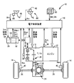
- FIG. 1 is a diagram illustrating a schematic configuration of a vehicle 10 to which the present invention is applied, and a block diagram illustrating a main part of a control system provided in the vehicle 10.
- a vehicle 10 includes an engine 12 that is an internal combustion engine as a driving power source for traveling, a transmission mechanism 16 that transmits the power of the engine 12 to the drive wheels 14, and the like.
- the speed change mechanism unit 16 is preferably used in, for example, an FF (front engine / front drive) type vehicle that is placed horizontally in the vehicle 10, and an output rotation member that constitutes one of the counter gear pairs 20 using the power of the engine 12.
- FF front engine / front drive
- the transmission mechanism 16, the counter gear pair 20, the final gear pair 22, the differential gear device (differential gear) 24, and the like constitute a transaxle (T / A).
- T / A transaxle
- the vehicle 10 is provided with, for example, a battery pack 28 that constitutes a battery as a power supply device, and an inverter 30 that is interposed in the exchange of electric power between the battery pack 28 and the electric motor M.
- the battery pack 28 is a power storage device (battery) as a DC power source that can be charged and discharged, for example, a battery cell 32 made of a secondary battery such as nickel metal hydride or lithium ion, and a battery as a cooling device that cools the battery cell 32.
- a blower that generates wind for cooling the cell 32, that is, a cooling fan (cooling blower) 34 is provided.
- the electric power stored in the battery pack 28 is supplied to the electric motor M through the inverter 30, and the power of the electric motor M is added to the power of the engine 12 as a driving force.
- the power generated by the motor M is stored in the battery pack 28 through the inverter 30.
- the vehicle 10 is provided with an electronic control unit 110 including a part of a vehicle battery cooling control unit for cooling the battery pack 28 using, for example, wind generated by the cooling fan 34.
- the electronic control unit 110 includes, for example, a so-called microcomputer having a CPU, a RAM, a ROM, an input / output interface, and the like.
- the CPU uses a temporary storage function of the RAM and follows a program stored in the ROM in advance. By performing signal processing, output control of the engine 12 and shift control of the transmission mechanism unit 16 are executed.
- the electronic control unit 110 for example, a crank angle (position) of a crankshaft of the detected engine 12 by the engine rotational speed sensor 36 signals representative of A CR and the engine rotational speed N E, the detected speed by the output rotational speed sensor 38 A signal representing the vehicle speed V corresponding to the output rotational speed N OUT of the mechanism unit 16, a signal representing the wheel speeds N WR and N WL corresponding to the rotational speed of each wheel detected by each wheel speed sensor 40, an accelerator opening sensor The signal indicating the accelerator opening Acc, which is the operation amount of the accelerator pedal 44 as the driver's acceleration request amount detected by the driver 42, and the brake-on when the foot brake 48, which is the service brake detected by the foot brake switch 46, is operated.
- an eco mode switch signal indicating an eco mode ON SW_ON in which an eco mode switch 50 as a travel mode selection switch for switching the travel mode to the eco mode is operated by the driver is selected.
- a signal representing the battery temperature TH BAT that is the temperature of the battery pack 28 and the charge / discharge current (or input / output current) I BAT that is the charge current or discharge current of the battery pack 28 detected by the battery monitoring unit 52 A signal indicating the voltage V BAT of the battery pack 28, a signal indicating the driving voltage V FAN of the cooling fan 34, and the like are supplied.
- the battery temperature TH BAT , the charge / discharge current I BAT , and the voltage V BAT are battery state signals necessary for calculating the state of charge (charge capacity) SOC of the battery pack 28.
- the drive voltage V FAN is a signal necessary for feedback control for controlling, for example, the rotational speed (fan rotational speed) N FAN of the cooling fan 34.
- the electronic control device 110 receives, for example, an engine output control command signal for output control of the engine 12, an electric motor drive control command signal for drive control of the electric motor M in the transmission mechanism unit 16, and a shift of the transmission mechanism unit 18.
- a hybrid control command signal such as a shift control command signal for control is output.
- a shift position switching control command signal for switching the shift position of the speed change mechanism unit 16 a display control command signal for clearly indicating to the user vehicle information related to vehicle travel, and a fan control command for operating the cooling fan 34
- a signal, a motor regeneration control command signal for controlling regenerative power of the motor M (regenerative braking torque in other words), and the like are output.
- the hybrid control command signal when the transmission mechanism 16 functions as, for example, a continuously variable transmission for example, the engine 12 is operated in an efficient operating range, while the driving force distribution between the engine 12 and the electric motor M is distributed.
- the speed ratio ⁇ as a continuously variable transmission of the speed change mechanism unit 16 is controlled by changing it to be optimal.
- the electronic control unit 110 is based on, for example, the actual accelerator opening Acc and the vehicle speed V from a relationship (not shown) (a user request output characteristic diagram and a user request output map) that is experimentally obtained and stored in advance. To calculate the user request power Puser * .
- the electronic control unit 110 executes control of the engine 12 and the electric motor M in order to improve power performance and fuel consumption.
- Such hybrid control in order to match the output speed N OUT determined by the engine rotational speed N E and vehicle speed V determined in order to operate the engine 12 in an operating region at efficiency, the transmission mechanism 16 is continuously It is made to function as a step transmission.
- the electronic control unit 110 is a type of operating curve of the well-known engine 12 (not shown) that has been experimentally obtained in advance so as to achieve both drivability and fuel efficiency, for example, during continuously variable speed travel.
- a fuel consumption rate curve (fuel consumption map, relationship) is stored in advance.
- the electronic control unit 110 requires the engine required power P necessary to satisfy the total required output Pall * so that the engine 12 can be operated while the operating point of the engine 12 is aligned with the optimum fuel consumption rate curve.
- each target value of the engine torque T E and the engine rotational speed N E for generating the E * target engine torque is (required value) (required engine torque) T E * and the target engine rotational speed (engine required rotational speed) N E * is determined, output control of the engine 12 is executed so that the target value is obtained, and the speed ratio ⁇ of the speed change mechanism unit 16 is controlled steplessly within the changeable range of the speed change.
- the vehicle 10 is provided with an eco mode switch 50 in the vicinity of the driver's seat, for example, and the eco mode can be selected by a switch operation in accordance with the driver's preference.
- this eco mode is used to drive the vehicle 10 so that the vehicle 10 can be driven in a state with good fuel efficiency while sufficiently pulling out the power performance of the vehicle 10, that is, the vehicle 10 can be driven with both fuel efficiency and driving performance (power performance) compatible.
- the normal mode set in advance it is possible to drive with priority on fuel efficiency over power performance, that is, driving in a state suitable for eco-driving with an emphasis on reducing fuel consumption
- This is a predetermined traveling mode that has been obtained and set in advance.
- the eco mode switch 50 is, for example, a push button switch, and the eco mode is selected (set) when pressed by the user. When the eco mode switch 50 is not pressed, a normal mode in which normal vehicle travel is executed is selected (set).
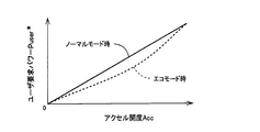
- FIG. 2 is a conceptual diagram illustrating the relationship between the accelerator opening Acc and the user requested power Puser * , for example.
- the solid line is for the normal mode
- the broken line is for the eco mode.
- the electronic control unit 110 suppresses the user required power Puser * with respect to the accelerator opening Acc in the calculation of the user required power Puser * , for example, in the eco mode as compared with the normal mode.
- FIG. 3 to 6 are diagrams for explaining the battery pack 28 mounted on the vehicle 10.
- FIG. 3 is a perspective view for explaining a main part of the vehicle 10 in a state where the battery pack 28 is mounted.
- FIG. 4 is an exploded perspective view for explaining the configuration of the battery pack 28.
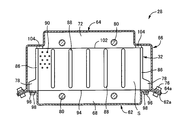
- FIG. 5 is a cross-sectional view for explaining the configuration of the battery pack 28.
- FIG. 6 is a schematic view showing a longitudinal section for explaining the air cooling structure of the battery pack 28.
- a longitudinal battery pack 28 having a relatively large capacity is mounted on the vehicle 10.
- the battery pack 28 is disposed below the under-seat cover panel 54 for supporting the bench-type rear seat, for example, with its longitudinal direction parallel to the width direction of the vehicle 10.
- the under-seat cover panel 54 is fixed on a floor panel 56 that functions as a floor of the passenger compartment and an underbody.
- the lower seat cover panel 54 has a lower end that is fixed to the floor panel 56 with bolts or the like, so that a longitudinal housing that extends in the width direction of the vehicle 10 is interposed between the lower seat cover panel 54 and the floor panel 56.
- a space 58 is formed.
- the passenger compartment refers to a space provided with a seat.
- the battery pack 28 is covered with the under-seat cover panel 54 and accommodated in the accommodating space 58, so that the battery pack 28 is adjacent to and separated from the passenger compartment in the body of the vehicle 10. Therefore, in this embodiment, the under-seat cover panel 54 functions as a battery pack cover. Further, since the floor panel 56 and the under-seat cover panel 54 are made of a magnetic conductor such as a steel plate, they also function as electromagnetic shields.
- the battery pack 28 has a plurality of flat prismatic battery cells 32 arranged in the thickness direction and penetrates between the battery cells 32 in one direction, that is, in the vertical direction.
- An assembled battery 60 as a battery module provided with a gap S, a battery case 66 including a lower case 62 and an upper case 64 for accommodating the assembled battery 60, and between the assembled battery 60 and the lower case 62.
- An air introduction duct 70 connected to the formed gas inflow chamber 68 to guide the air in the vehicle interior into the gas inflow chamber 68, and a gas discharge chamber formed between the assembled battery 60 and the upper case 64. 72, and an air discharge duct 74 for discharging the air in the gas discharge chamber 72.
- the lower case 62 and the upper case 64 constituting the lower part and the upper part of the battery case 66 are, for example, bent from a single metal plate material by press working with a fold line parallel to the longitudinal direction of the assembled battery 60 as a boundary.
- the mounting walls 62a and 64a located at both ends in the width direction are integrally fixed to each other by a fixing screw 76 that passes through mounting holes 62b and 64b provided in the mounting walls 62a and 64a. .
- the battery cell 32 is, for example, a resin-made flat box having a plurality of battery cases inside, and is provided with a positive terminal and a negative terminal (not shown) connected in series at the upper part of the side surface, and its longitudinal direction ( (Width direction), that is, the left-right direction in FIG. 5 is arranged to be the front-rear direction of the vehicle. Moreover, the battery cell 32 is provided with the leg part 78 which protrudes in the width direction (longitudinal direction) from the lower part of the side surface.
- the plurality of battery cells 32 are overlapped with each other in the thickness direction and arranged in a plurality, and are brought close to each other by two pairs of restraining rods (restraining members) 80 provided above and below the battery cell 32, respectively. Are pressed against each other by a pair of constraining plates (end plates) 82 that are fastened in the direction to be tightened.
- the restraining plate 82 is provided with two pairs of brackets 84 protruding in the vertical direction in order to be fixed to the restraining rod 80.
- a pair of battery cells 32 are provided on the overlapping surface, that is, the opposing surfaces of the battery cells 32 so as to be continuous in the short side direction, that is, the vertical direction, at both ends of the opposing surface in the long side direction.
- a plurality of (five in the present embodiment) ridges 88 that are continuous in the vertical direction of the opposing surface at the middle portion in the long side direction, and a fixed arrangement between the ridges 86, 88.
- a plurality of small protrusions 90 protruding from the facing surface at a predetermined interval so as to have a density are provided.
- the ridges 86 and 88 are formed at locations corresponding to the positions of the partition walls in which the plurality of battery cases are formed in the battery cell 32, and come into contact with the ridges 86 and 88 of the adjacent battery cells 32. Thus, the battery cell 32 is prevented from being deformed by receiving the compressive force generated by the restraining rod 80. Further, the ridges 86 and 88 and the small protrusions 90 are for forming a slight gap S between the battery cells 32, and are formed to have a protruding amount of about 1.0 mm, for example.
- a slit-like gap S having a width dimension of about 2.0 mm that penetrates in the vertical direction is formed between the battery cells 32, and a width dimension that penetrates in the vertical direction between the battery cell 32 and the restraining plate 82.
- the protruding surface adjacent to the mounting wall 62 a of the lower case 62 is for supporting both ends of the battery cell 32, and functions as a support surface 92. That is, the inner wall surface of the lower case 62 corresponds to the width direction dimension of the battery cell 32, has an interval smaller than the width dimension, and is parallel to each other in the thickness direction of the battery cell 32, ie, the assembled battery 60 A pair of support surfaces 92 extending in the longitudinal direction are formed.
- Each battery in a state in which a pair of seating surfaces 96 positioned at both ends in the longitudinal direction of the lower end surface 94 of the gap S between the battery cells 32 are seated on the pair of support surfaces 92.
- the gas inflow chamber 68 is formed by the lower end surface 94 of each battery cell 32 and the lower case 62.
- Each battery cell 32 is screwed through a hole 100 provided in the support surface 92 of the lower case 62 with a bottomed cylindrical nut (not shown) embedded in the seating surface 96 by insert molding, for example. Is fixed to the lower case 62.
- the assembled battery is in contact with both ends of the upper end surface 102 of the battery cell 32 at positions corresponding to both ends of the upper end surface 102 of the battery cell 32 on the inner wall surface of the upper case 64.
- a pair of longitudinal seal members 104 extending in the longitudinal direction of 60 are fixed by, for example, an adhesive, and a gas discharge chamber 72 is provided on a portion between the pair of seal members 104 of the upper case 64 and the battery cell 32. It is formed between the end face 102.
- One end of the air introduction duct 70 is connected to the opening between the end of the lower case 62 and the lower portion of the restraining plate 82, and the other end is connected to the cooling fan 34 that functions as a blower fan, an intake fan, or the like.
- the cooling fan 34 functions as a blower fan, an intake fan, or the like, and its suction port is connected to an intake duct (not shown) for sucking air for cooling the battery cells 32 from the vehicle interior.
- the intake duct is connected to a plurality of slits 106 provided at the longitudinal end of the under-seat cover panel 54, and constitutes a part of the air introduction path. Therefore, this slit 106 functions as an opening of the air introduction path.
- the gas inflow chamber 68 in the battery case 66 is communicated with the vehicle interior via the air introduction duct 70, the cooling fan 34, the intake duct (not shown), the slit 106, and the like.
- the air discharge duct 74 is an exhaust duct for discharging the air after cooling the battery cells 32 to the outside of the vehicle, and has one end connected to an opening between the end of the upper case 64 and the upper portion of the restraint plate 82. The other end communicates with an opening (not shown) that communicates with the outside of the vehicle.
- the gas discharge chamber 72 in the battery case 66 is communicated with the outside of the vehicle via the air discharge duct 74 and the like. Therefore, when the cooling fan 34 is operated, relatively high-temperature air in the accommodation space 58 is prevented from being sucked and blown to the battery pack 28, and cold air in the vehicle compartment is reliably sucked.
- the cooling fan 34 provided in the air introduction duct 70 is controlled by a fan control command signal from the electronic control device 110 in order to suppress an increase in the battery temperature TH BAT. Is activated.
- the cooling fan 34 is actuated, for example, as indicated by the one-dot chain line arrow F in FIG. 6, the air drawn into the vehicle interior by the cooling fan 34 is converted into the slit 106, the intake duct (not shown), the cooling fan 34, The air is introduced to the outside of the vehicle through the air introduction duct 70, the gas inflow chamber 68, the gap S between the battery cells 32, the gas discharge chamber 72, the air discharge duct 74, and the like.
- each battery cell 32 is cooled by the air led from the vehicle interior being passed through the gaps S between the battery cells 32. Therefore, in the present embodiment, the slit 106, the above-described intake duct (not shown), the cooling fan 34, the air introduction duct 70, the gas inflow chamber 68, and the like function as an air introduction path, and the gas exhaust chamber 72, the air exhaust duct 74, and the like. It functions as an air lead-out path.
- the air flow F as shown by the one-dot chain line arrow in FIG. 6 is a wind generated by the cooling fan 34, and the air volume Q of the cooling fan 34 is approximately proportional to the fan rotation speed N FAN , for example. As the speed N FAN becomes higher, the air volume Q of the cooling fan 34 increases. In the present embodiment, unless otherwise distinguished, the air volume Q of the cooling fan 34 and the fan rotation speed N FAN are treated as the same, and the air volume Q of the cooling fan 34 is determined by the level of the fan rotation speed N FAN . To express.
- the cooling fan 34 is operated so as to control the fan rotation speed N FAN according to the battery temperature TH BAT to improve the cooling performance. It is improving. Specifically, the electronic control unit 110 increases the fan rotation speed N FAN as the battery temperature TH BAT is higher or the vehicle speed V is higher (that is, the air volume Q of the cooling fan 34 is increased). The relationship (fan rotation speed map) as shown in FIG. 7 which is obtained and set in advance is provided. The electronic control unit 110 calculates the fan rotation speed N FAN based on the battery temperature TH BAT from the fan rotation speed map as shown in FIG. 7, for example, and the cooling fan 34 so as to obtain the calculated fan rotation speed N FAN.
- the fan control command signal for operating is output.
- the fan rotation speed map shown in FIG. 7 is set so that, for example, an appropriate cooling performance according to the battery temperature TH BAT is ensured and the life of the battery pack 28 (battery life) is improved.
- N FAN the higher the noise and the lower the NV performance (noise / vibration performance)
- the fan rotational speed NFAN is set to increase as the vehicle speed V increases.
- the NV performance and the cooling performance (battery life) are set to be compatible.
- the fan rotation speed N FAN can be set to a higher rotation if priority is given to the cooling performance (battery life).
- the rotational speed N FAN is set to be suppressed. Therefore, in this embodiment, for example, in order to improve the battery life, the higher the battery temperature TH BAT is, the lower the electric power that can be stored in the battery pack 28 is, for example, the storage of the regenerative energy amount generated by the motor M, for example. By suppressing this, the rise in battery temperature TH BAT is suppressed. Therefore, when the battery temperature TH BAT is relatively high, it may be difficult to improve the practical fuel consumption.
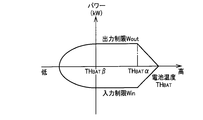
- FIG. 8 is a relationship (input / output restriction map) obtained and determined experimentally in advance between the battery temperature TH BAT and the input / output restriction Win / Wout in the battery pack 28.
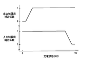
- FIG. 9 is a relationship (input / output limiting correction coefficient map) determined and determined experimentally in advance between the state of charge SOC and the input / output limiting Win / Wout correction coefficient.
- the basic values of the input limit Win and the output limit Wout are set based on the battery temperature TH BAT from the input / output limit map of FIG. 8, and the input limit is set based on the state of charge SOC from the input / output limit correction coefficient map of FIG.
- Correction coefficient and output restriction correction coefficient are respectively set, and input restriction Win and output restriction Wout are set by multiplying the basic values of input restriction Win and output restriction Wout by the input restriction correction coefficient and output restriction correction coefficient, respectively. Is done. For example, as shown in FIG. 8, in a high temperature region where battery temperature TH BAT is higher than the predetermined high temperature TH BAT alpha, higher the battery temperature TH BAT is high, since the set value of the input and output limits Win / Wout is lowered As a result, as the battery temperature TH BAT increases, the power that can be stored in the battery pack 28 (for example, the amount of regenerative energy generated by the motor M) is suppressed, making it difficult to improve the practical fuel consumption. On the other hand, for example, as shown in FIG.
- the vehicle 10 of the present embodiment includes an eco mode switch 50 and can select the eco mode according to the preference of the driver.
- the driver selects the eco mode
- priority may be given to improving the fuel efficiency, and the NV performance may be lowered by relaxing the standard that satisfies the NV performance. Therefore, in the present embodiment, for example, when the eco mode is selected, the fan rotation speed N FAN is increased (that is, the air volume Q of the cooling fan 34 is increased) compared to the normal mode where the eco mode is not selected. ).
- the fan rotation speed is selected when the eco mode is selected.
- the fan rotational speed N FAN is increased when the eco mode is selected ( That is, the increase in the air volume Q of the cooling fan 34) is not executed.
- FIG. 10 is a functional block diagram for explaining the main part of the control function by the electronic control unit 110.
- the travel mode determination unit that is, the travel mode determination unit 112 determines whether or not the eco mode is selected by the eco mode switch 50, for example. Specifically, the traveling mode determination unit 112 determines whether or not the eco mode is selected based on whether or not the eco mode ON SW_ON is output. That is, the traveling mode determination unit 112 determines that the eco mode is selected when the eco mode on SW_ON is output, and determines that the normal mode is selected when the eco mode on SW_ON is not output. .
- Battery temperature determination unit that is, battery temperature determining means 114, for example, battery temperature TH BAT is equal to or less than a predetermined low temperature TH BAT beta power input and output is reduced in the battery pack 28, that is, battery temperature TH BAT is predetermined low It is determined whether or not the temperature TH BAT ⁇ is exceeded.
- the fan drive control unit determines that the normal mode is selected by the travel mode determination means 112, or determines that the eco mode is selected by the travel mode determination means 112. If the battery temperature determination unit 114 determines that the battery temperature TH BAT is equal to or lower than the predetermined low temperature TH BAT ⁇ , for example, a fan rotation speed map as shown in FIG. 7 (that is, the solid line in FIG. 11).
- the fan rotation speed N FAN is calculated based on the battery temperature TH BAT from the fan rotation speed map in the normal mode as shown in the figure, and the cooling fan 34 is operated so that the calculated fan rotation speed N FAN is obtained.
- a fan control command signal is output.
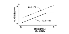
- the fan drive control unit 116 determines that the eco mode is selected by the travel mode determination unit 112 and the battery temperature TH BAT exceeds the predetermined low temperature TH BAT ⁇ by the battery temperature determination unit 114, for example. If it is determined, for example calculates the fan rotation speed N fAN based fan speed map eco mode shown in broken lines on the battery temperature TH BAT in FIG. 11, is the calculated fan speed N fAN A fan control command signal for operating the cooling fan 34 is output so as to be obtained.
- a solid line is a normal mode fan rotation speed map used when the normal mode is selected, and is the same map as the fan rotation speed map shown in FIG. 7, for example.
- the fan rotation speed N FAN is shown. Is a map that is set in advance so that the airflow Q is easily raised (that is, the airflow rate Q of the cooling fan 34 is easily increased).
- the fan rotation speed NFAN is increased by an amount that relaxes the criterion that satisfies the NV performance (ie, The air volume Q of the cooling fan 34 is increased).
- the fan drive control means 116 calculates the fan rotation speed N FAN from the fan rotation speed map based on the battery temperature TH BAT .
- the fan rotation speed map is set with the vehicle speed V as a variable, the fan rotation speed is calculated.
- the fan rotation speed NFAN may be calculated based on the vehicle speed V from the speed map.
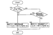
- FIG. 12 illustrates a control operation for ensuring the cooling performance of the battery pack 28 while satisfying the main part of the control operation of the electronic control unit 110, that is, the NV performance, and improving the battery life and the fuel efficiency.
- This is a flowchart, and is repeatedly executed with a very short cycle time of, for example, about several milliseconds to several tens of milliseconds.
- step (hereinafter, step is omitted) S10 corresponding to the travel mode determination means 112 means, for example, whether or not the eco mode is selected based on whether or not the eco mode ON SW_ON is output. Is judged. If the determination in S10 is affirmative, it is determined in S20 corresponding to the battery temperature determination means 114, for example, whether the battery temperature TH BAT exceeds a predetermined low temperature TH BAT ⁇ . If the determination in S10 is negative or the determination in S20 is negative, in S30 corresponding to the fan drive control means 116, for example, the battery temperature from the normal mode fan rotation speed map as shown by the solid line in FIG.
- a fan rotation speed N FAN is calculated based on TH BAT, and a fan control command signal for operating the cooling fan 34 so as to obtain the calculated fan rotation speed N FAN is output.
- the fan rotation speed NFAN is likely to be increased compared to the normal mode fan rotation speed map (solid line), for example.
- the fan rotation speed N FAN is calculated based on the battery temperature TH BAT from the eco-mode fan rotation speed map as shown by the broken line in FIG. 11 set in advance, and the calculated fan rotation speed N FAN is obtained. Then, a fan control command signal for operating the cooling fan 34 is output.
- the cooling fan 34 is provided as a cooling device, and the battery (battery pack 28, battery cell 32) is cooled using the wind generated by the cooling fan 34.
- the eco mode which is a predetermined travel mode for performing the travel with priority
- the air volume Q of the cooling fan 34 is increased as compared to the normal mode in which the eco mode is not selected (that is, since fan speed N fAN is raised a), for example, when the eco mode is selected is given priority cell cooling than improve NV performance, which can be accumulated in the battery pack 28 in the battery temperature TH BAT is further lowered
- the regenerative energy by the electric power for example, the electric motor M is increased, and the practical fuel consumption can be improved.
- the battery life can be improved by further lowering the battery temperature TH BAT .
- the air flow rate of the cooling fan 34 can be improved in order to improve the NV performance from the viewpoint that the criteria satisfying the NV performance may be relaxed and the improvement in the cooling performance may be prioritized.
- Q increased i.e. increase of the fan rotational speed N fAN
- the air volume Q of the cooling fan 34 i.e. the fan rotational speed N fAN
- the battery temperature TH BAT is equal to or lower than a predetermined temperature (predetermined low temperature TH BAT ⁇ ) at which the input / output of electric power in the battery pack 28 decreases
- a predetermined temperature predetermined low temperature TH BAT ⁇
- an increase in the air volume Q of the cooling fan 34 that is, since the fan rotation speed N FAN is not increased, for example, it is avoided that the regenerative energy must be decreased by increasing the cooling performance of the battery pack 28, for example. That is, it is avoided that the practical fuel consumption deteriorates when the user desires to drive with priority on the fuel consumption performance (when the eco mode is selected).
- the eco-mode switch 50 that allows the user to select and operate the eco-mode is provided. Therefore, when the user desires to travel with priority on fuel efficiency, the NV performance standards are relaxed to reduce the cooling performance. Is appropriately improved.
- the predetermined travel mode for performing the travel with priority on the fuel efficiency is preliminarily performed so that the vehicle 10 can be driven in a state with good fuel efficiency while sufficiently extracting the power performance of the vehicle 10.
- the eco mode is set in advance for running so that the vehicle can be driven in a state in which the fuel efficiency is prioritized over the power performance.
- the air volume Q of the cooling fan 34 is increased (that is, the fan rotation speed N FAN can be increased). Practical fuel consumption can be improved and battery life can be improved by further reducing the temperature TH BAT .
- the air flow rate Q of the cooling fan 34 is increased compared to the normal mode fan rotation speed map used in the normal mode when the eco mode is not selected. Since the eco-mode fan rotation speed map that is set in advance is used so as to be easy (that is, the fan rotation speed N FAN is easily increased), for example, when the eco-mode is selected, compared with the normal mode The air flow rate Q of the cooling fan 34 is reliably (appropriately) increased (that is, the fan rotation speed N FAN Is definitely raised).
- the air volume Q of the cooling fan 34 is increased (that is, the fan rotation speed N FAN is increased), so that the battery temperature TH BAT can be further lowered to store power in the battery pack 28.
- the regenerative energy by the electric power, for example, the electric motor M is increased, and the practical fuel consumption can be surely improved.
- the battery pack is obtained by flowing the wind generated by the cooling fan 34 that is the air flow F as indicated by the one-dot chain line arrow in FIG. 6 through the gap S between the battery cells 32.
- the present invention is not necessarily limited to such a configuration.
- the battery pack 28 may be cooled by using the wind generated by the cooling fan 34.
- the battery pack 28 (each battery cell 32) is configured to be cooled as in a water cooling method for cooling a known engine, and the refrigerant used at that time is cooled using wind generated by the cooling fan 34.
- the battery pack may be indirectly cooled by the wind.
- the configuration may be such that the temperature of the wind itself passing through the gap S between the battery cells 32 is cooled, and the temperature of the wind itself is cooled using the wind generated by the cooling fan 34.
- the cooling fan 34 is provided as a cooling device.
- a cooling device that directly or indirectly cools the battery pack by operating an actuator such as a pump or a compressor.
- the present invention can be applied.
- a cooling pump is provided as a cooling device, and coolant for cooling the battery pack in the water cooling method or air cooling method is circulated by the cooling pump, and when priority is given to fuel efficiency, the circulation flow rate (cooling amount) by the cooling pump is increased. You may make it let it.
- the increase in the cooling amount of the cooling device is suppressed for improving the NV performance, whereas when the fuel efficiency is prioritized, the cooling of the cooling device is reduced by relaxing the standard that satisfies the NV performance. Since the cooling performance can be improved by increasing the amount, it is possible to secure the cooling performance of the battery pack while satisfying the NV performance, thereby improving the battery life and the fuel efficiency.
- the generation of the driving force with respect to the accelerator opening Acc is controlled and the operation of the air conditioner is controlled.
- the control may be performed so as to moderate the generation of the driving force with respect to the accelerator opening Acc as compared with, for example, the normal mode.
- the transmission mechanism 16 is exemplified as a continuously variable transmission.
- the present invention is also applied to various other transmission mechanisms such as a planetary gear type automatic transmission. obtain.
- the eco mode switch 50 is a push button switch, but various other switches such as a seesaw type switch and a slide type switch can be used. Further, instead of the eco mode switch 50, for example, a device that can select the eco mode in response to the driver's voice regardless of manual operation may be used. In short, the present invention can be applied if the driver (user) is configured as a travel mode selection device that can select and operate the eco mode. Moreover, this driving
Landscapes
- Engineering & Computer Science (AREA)
- Transportation (AREA)
- Mechanical Engineering (AREA)
- Chemical & Material Sciences (AREA)
- Combustion & Propulsion (AREA)
- Sustainable Development (AREA)
- Life Sciences & Earth Sciences (AREA)
- Sustainable Energy (AREA)
- Power Engineering (AREA)
- Automation & Control Theory (AREA)
- Manufacturing & Machinery (AREA)
- Chemical Kinetics & Catalysis (AREA)
- Electrochemistry (AREA)
- General Chemical & Material Sciences (AREA)
- Electric Propulsion And Braking For Vehicles (AREA)
Abstract
NV性能を満たしつつ電池の冷却性能を確保して、電池寿命の向上と燃費性能の向上とを図る。 エコモードが選択されているときには、ノーマルモードと比較して、冷却ファン34の風量Qが増大させられる(すなわちファン回転速度NFANを上昇させられる)ので、例えばエコモードが選択されたときはNV性能の向上よりも電池冷却が優先され、電池温度THBATが一層下げられることで電池パック28に蓄電可能な電力例えば電動機Mによる回生エネルギが増大させられて実用燃費を向上させることができる。また、電池温度THBATが一層下げられることで電池寿命を向上させることもできる。つまり、ユーザが燃費性能を優先した走行を望む場合にはNV性能を満たす基準を緩和し、NV性能を満たす基準を緩和する分、冷却ファン34の風量Qを増大させて冷却性能を向上させる。
Description
本発明は、冷却装置を用いて電池を冷却する車両用電池の冷却制御装置に関するものである。
冷却装置を用いて電池を冷却する車両用電池の冷却制御装置が良く知られている。例えば、特許文献1に示された車両用電源装置がそれである。この特許文献1には、複数個の電池セルがそれらの間に各々隙間を形成して電池ケース内に収容され、その電池ケース内に送風機によって導入した車室内の空気をその隙間に一方向に流すように構成してそれら電池セルを冷却することが記載されている。
ここで、例えば電池の寿命(耐久性)を向上させる為に、電池温度が高くなる程、前記送風機の冷却風量を増大して冷却性能を向上させることが提案されている。また、別の観点からは、例えば電池の寿命を向上させる為に、電池の温度が比較的高い場合には、電池に蓄電可能な電力を抑制(制限)して例えば回転機が発生する回生エネルギ量の蓄電を抑制して、電池温度の上昇を抑制することが提案されている。その為、電池温度が比較的高くなると、実用燃費を向上させ難くなる可能性がある。そこで、例えば実用燃費を向上させる為に、電池温度が高くなる程、送風機の冷却風量を一層増大して、冷却性能を一層向上させることが考えられる。しかしながら、例えば冷却性能を一層向上させる為に送風機の冷却流量を増大する程すなわち送風機の回転速度を上げる程、騒音が増大して、NV性能(騒音・振動性能)が低下する可能性がある。このように、電池寿命の向上を図りつつ燃費性能を向上させようとすればNV性能を向上させ難くなり、電池寿命の向上を図りつつNV性能を向上させようとすれば実用燃費を向上させ難くなる。このようなことから、電池寿命の向上を図りつつ燃費性能とNV性能とのバランスを取ることが望まれる。見方を換えれば、NV性能を満たしつつ電池の冷却性能を確保して、電池寿命の向上と燃費性能の向上とを図ることが望まれる。このような、課題は未公知であると共に、冷却に伴って騒音を発生する冷却装置に共通するものであり、NV性能を満たしつつ電池寿命の向上と燃費性能の向上とを両立させるように電池を冷却することについて、未だ提案されていない。
本発明は、以上の事情を背景として為されたものであり、その目的とするところは、NV性能を満たしつつ電池の冷却性能を確保して、電池寿命の向上と燃費性能の向上とを図ることができる車両用電池の冷却制御装置を提供することにある。
前記目的を達成するための本発明の要旨とするところは、(a) 冷却装置によって電池を冷却する車両用電池の冷却制御装置であって、(b) 燃費性能を優先するときには、その燃費性能を優先しないときと比較して、前記冷却装置の冷却量を増大させることにある。
このようにすれば、燃費性能を優先するときには、その燃費性能を優先しないときと比較して、前記冷却装置の冷却量が増大させられるので、例えば燃費性能を優先するときはNV性能の向上よりも電池冷却が優先され、電池の温度が一層下げられることで電池に蓄電可能な電力例えば回生エネルギが増大させられて実用燃費を向上させることができる。また、電池の温度が一層下げられることで電池寿命を向上させることもできる。つまり、ユーザが燃費性能を優先するときにはNV性能の基準を緩和して冷却性能の向上を優先しても良いという観点から、NV性能の向上の為に冷却装置の冷却量の増大を抑制していることに対して、NV性能の基準を緩和する分、冷却性能を向上させるのである。よって、NV性能を満たしつつ電池の冷却性能を確保して、電池寿命の向上と燃費性能の向上とを図ることができる。尚、冷却装置の冷却量を増大させることは冷却装置におけるエネルギ消費が増大することになるが、電池の温度が比較的高い場合の回生エネルギの抑制分の方が格段に大きいので、この冷却装置におけるエネルギ消費の増大分を差し引いても実用燃費が向上する。
ここで、好適には、運転者が走行様式を選択操作できる走行様式選択装置を備え、前記燃費性能を優先するときとは、前記走行様式選択装置によりその燃費性能を優先した走行を行う為の所定の走行様式が選択されているときである。このようにすれば、運転者(ユーザ)が燃費性能を優先するときにはNV性能の基準を緩和して冷却性能が適切に向上される。
また、好適には、前記冷却装置として送風機を備え、前記送風機によって発生させる風を用いて電池を冷却するものであり、燃費性能を優先した走行を行う為の所定の走行様式が選択されているときには、その所定の走行様式が選択されていないときと比較して、前記送風機の風量を増大させることにある。このようにすれば、例えば所定の走行様式が選択されたときはNV性能の向上よりも電池冷却が優先され、電池の温度が一層下げられることで電池に蓄電可能な電力例えば回生エネルギが増大させられて実用燃費を向上させることができる。また、電池の温度が一層下げられることで電池寿命を向上させることもできる。つまり、ユーザが燃費性能を優先した走行を望む場合にはNV性能の基準を緩和して冷却性能の向上を優先しても良いという観点から、NV性能の向上の為に送風機の風量の増大を抑制していることに対して、NV性能の基準を緩和する分、冷却性能を向上させるのである。よって、NV性能を満たしつつ電池の冷却性能を確保して、電池寿命の向上と燃費性能の向上とを図ることができる。尚、送風機の風量を増大させることは送風機における電力消費が増大することになるが、電池の温度が比較的高い場合の回生エネルギの抑制分の方が格段に大きいので、この送風機における電力消費の増大分を差し引いても実用燃費が向上する。
また、好適には、前記電池の温度がその電池における電力の入出力が減少する所定の温度以下であるときには、前記風量の増大を実行しないことにある。このようにすれば、例えば電池の冷却性能を高めることで却って回生エネルギを減少させなければならないようなことが回避される。つまり、ユーザが燃費性能を優先した走行を望む場合に却って実用燃費が悪化してしまうことが回避される。
また、好適には、運転者が前記所定の走行様式を選択操作できる走行様式選択装置を備えていることにある。このようにすれば、運転者(ユーザ)が燃費性能を優先した走行を望む場合にはNV性能の基準を緩和して冷却性能が適切に向上される。
また、好適には、前記所定の走行様式は、車両の動力性能を充分引き出しつつ燃費の良い状態で運転可能なように走行を行う為の予め設定されたノーマルモードに比較して、動力性能よりも燃費性能を優先した状態で運転可能なように走行を行う為の予め設定されたエコモードである。このようにすれば、例えばエコモードが選択されているときには前記送風機の風量が増大させられるので、ノーマルモードが選択されているときと比較して、電池の温度が一層下げられることで実用燃費を向上させることができると共に、電池寿命を向上させることができる。
また、好適には、前記電池の温度が高い程或いは車速が高い程、前記送風機の風量を増大させるように予め設定された関係を有し、前記燃費性能を優先した走行を行う為の所定の走行様式が選択されているときには、その所定の走行様式が選択されていないときに用いる前記関係と比較して前記風量が増大されやすいように予め設定されている前記関係を用いることにある。このようにすれば、例えば燃費性能を優先した走行を行う為の所定の走行様式が選択されているときには、その所定の走行様式が選択されていないときと比較して、送風機の風量が確実に(適切に)増大させられる。
また、好適には、前記電池の温度が高い程、その電池に蓄電可能な電力を抑制することにある。このようにすれば、例えば燃費性能を優先するときに前記冷却装置の冷却量が増大させられることにより、電池の温度が一層下げられることで電池に蓄電可能な電力例えば回生エネルギが増大させられて実用燃費を確実に向上させることができる。より具体的には、燃費性能を優先した走行を行う為の所定の走行様式が選択されたときに前記送風機の風量が増大させられることにより、電池の温度が一層下げられることで電池に蓄電可能な電力例えば回生エネルギが増大させられて実用燃費を確実に向上させることができる。
また、好適には、前記車両用電池の冷却制御装置を備える車両は、動力源から駆動輪までの動力伝達経路に車両用動力伝達装置を備えている。この動力源としては、例えば燃料の燃焼によって動力を発生する内燃機関等のガソリンエンジンやディーゼルエンジン等が好適に用いられるが、電動機等の他の原動機を単独で或いはエンジンと組み合わせて採用することもできる。
また、好適には、前記車両用動力伝達装置は、変速機構部単体、トルクコンバータ及び複数の変速比を有する変速機構部、或いはこの変速機構部等に加え減速機構部やディファレンシャル機構部により構成される。この変速機構部は、例えば複数組の遊星歯車装置の回転要素が係合装置によって選択的に連結されることにより複数のギヤ段(変速段)が択一的に達成される例えば前進4段、前進5段、前進6段、更にはそれ以上の変速段を有する等の種々の遊星歯車式自動変速機、常時噛み合う複数対の変速ギヤを2軸間に備えてそれら複数対の変速ギヤのいずれかを同期装置によって択一的に動力伝達状態とする同期噛合型平行2軸式変速機、その同期噛合型平行2軸式変速機ではあるが油圧アクチュエータにより駆動される同期装置によって変速段が自動的に切換られることが可能な同期噛合型平行2軸式自動変速機、同期噛合型平行2軸式自動変速機であるが入力軸を2系統備えて各系統の入力軸にクラッチがそれぞれつながり更にそれぞれ偶数段と奇数段へと繋がっている型式の変速機である所謂DCT(Dual Clutch Transmission)、動力伝達部材として機能する伝動ベルトが有効径が可変である一対の可変プーリに巻き掛けられ変速比が無段階に連続的に変化させられる所謂ベルト式無段変速機、共通の軸心まわりに回転させられる一対のコーンとその軸心と交差する回転中心回転可能な複数個のローラがそれら一対のコーンの間で挟圧されそのローラの回転中心と軸心との交差角が変化させられることによって変速比が可変とされた所謂トラクション型無段変速機、エンジンからの動力を第1電動機及び出力軸へ分配する例えば遊星歯車装置で構成される差動機構とその差動機構の出力軸に設けられた第2電動機とを備えてその差動機構の差動作用によりエンジンからの動力の主部を駆動輪側へ機械的に伝達しエンジンからの動力の残部を第1電動機から第2電動機への電気パスを用いて電気的に伝達することにより電気的に変速比が変更される電気式無段変速機として機能する自動変速機、或いはエンジン軸や出力軸などに動力伝達可能に電動機が備えられる所謂パラレル式のハイブリッド車両に搭載される自動変速機などにより構成される。
以下、本発明の実施例を図面を参照しつつ詳細に説明する。
図1は、本発明が適用される車両10の概略構成を説明する図であると共に、車両10に設けられた制御系統の要部を説明するブロック線図である。図1において、車両10は、走行用駆動力源としての内燃機関であるエンジン12、エンジン12の動力を駆動輪14側へ伝達する変速機構部16などを備えている。変速機構部16は、例えば車両10において横置きされるFF(フロントエンジン・フロントドライブ)型車両に好適に用いられるものであり、エンジン12の動力をカウンタギヤ対20の一方を構成する出力回転部材としての出力歯車18から、動力伝達装置としてのカウンタギヤ対20、ファイナルギヤ対22、差動歯車装置(ディファレンシャルギヤ)24、及び一対の車軸(ドライブシャフト(D/S))26等を順次介して一対の駆動輪14へ伝達する。これら変速機構部16、カウンタギヤ対20、ファイナルギヤ対22、差動歯車装置(ディファレンシャルギヤ)24等によりトランスアクスル(T/A)が構成される。尚、以下においては、駆動力源としてのエンジン12及び電動機Mを備えたハイブリッド車両に本発明の電子制御装置110が適用された場合の例について説明するが、本発明の電子制御装置110が適用される車両は通常のエンジン車両、ハイブリッド車両、電動車両などどのような形式の車両であっても構わない。
また、車両10には、例えば電源装置としての電池を構成する電池パック28と、電池パック28と電動機Mとの間の電力のやりとりに介在するインバータ30とが備えられている。電池パック28は、例えば充放電可能な直流電源としての蓄電装置(バッテリ)であり、例えばニッケル水素やリチウムイオン等の二次電池から成る電池セル32、電池セル32を冷却する冷却装置としてその電池セル32を冷却する為の風を発生する送風機すなわち冷却ファン(冷却ブロワ)34などを備えている。そして、例えば車両加速走行時には、電池パック28に蓄電された電力がインバータ30を通して電動機Mへ供給され、エンジン12の動力に電動機Mの動力が駆動力として加えられる。また、車両減速走行時の回生制動の際には、電動機Mにより発電された電力がインバータ30を通して電池パック28に蓄電される。
更に、車両10には、例えば冷却ファン34によって発生させる風を用いて電池パック28を冷却する為の車両用電池の冷却制御装置の一部を含む電子制御装置110が備えられている。電子制御装置110は、例えばCPU、RAM、ROM、入出力インターフェース等を備えた所謂マイクロコンピュータを含んで構成されており、CPUはRAMの一時記憶機能を利用しつつ予めROMに記憶されたプログラムに従って信号処理を行うことにより、エンジン12の出力制御、変速機構部16の変速制御などを実行する。
電子制御装置110には、例えばエンジン回転速度センサ36により検出されたエンジン12のクランク軸のクランク角度(位置)ACR及びエンジン回転速度NEを表す信号、出力回転速度センサ38により検出された変速機構部16の出力回転速度NOUTに対応する車速Vを表す信号、各車輪速センサ40により検出された各車輪の回転速度に対応する車輪速NWR,NWLを表す信号、アクセル開度センサ42により検出された運転者の加速要求量としてのアクセルペダル44の操作量であるアクセル開度Accを表す信号、フットブレーキスイッチ46により検出された常用ブレーキであるフットブレーキ48が操作されたブレーキオンBONを表す信号、運転者が走行様式を選択操作できる走行様式選択装置例えば運転者が所定の走行様式を選択操作できる走行様式選択装置すなわち走行モードをエコモードに切り替える為の走行モード選択スイッチとしてのエコモードスイッチ50がドライバーによりスイッチ操作されたエコモードオンSW_ONを表すエコモードスイッチ信号などが、それぞれ供給される。加えて、電池監視ユニット52により検出された、電池パック28の温度である電池温度THBATを表す信号、電池パック28の充電電流又は放電電流である充放電電流(或いは入出力電流)IBATを表す信号、電池パック28の電圧VBATを表す信号、及び冷却ファン34の駆動電圧VFANを表す信号などが供給される。尚、電池温度THBAT、充放電電流IBAT、及び電圧VBATの各信号は、電池パック28の充電状態(充電容量)SOCを算出する為に必要な電池状態信号である。また、駆動電圧VFANは、例えば冷却ファン34の回転速度(ファン回転速度)NFANを制御する為のフィードバック制御に必要な信号である。
また、電子制御装置110からは、例えばエンジン12の出力制御の為のエンジン出力制御指令信号や変速機構部16内の電動機Mの駆動制御の為の電動機駆動制御指令信号や変速機構部18の変速制御の為の変速制御指令信号などのハイブリッド制御指令信号が出力される。また、例えば変速機構部16のシフトポジションを切り替える為のシフトポジション切換制御指令信号、車両走行に関わる車両情報をユーザに明示する為の表示制御指令信号、冷却ファン34を作動させる為のファン制御指令信号、電動機Mの回生電力(見方を換えれば回生制動トルク)を制御する為の電動機回生制御指令信号等が、それぞれ出力される。
変速機構部16が例えば無段変速機として機能する場合の上記ハイブリッド制御指令信号としては、例えばエンジン12を効率のよい作動域で作動させる一方で、エンジン12と電動機Mとの駆動力の配分を最適になるように変化させて変速機構部16の無段変速機としての変速比γを制御する。具体的には、電子制御装置110は、例えば予め実験的に求められて記憶された不図示の関係(ユーザ要求出力特性図、ユーザ要求出力マップ)から実際のアクセル開度Acc及び車速Vに基づいてユーザ要求パワーPuser*を算出する。次に、電子制御装置110は、ユーザ要求パワーPuser*と例えば電池パック28の充電状態SOCに基づく充電要求値(充電要求パワー)Pchg*とから必要なトータル要求出力Pall*(=Puser*+Pchg*)を算出する。更に、電子制御装置110は、そのトータル要求出力Pall*が得られるように、伝達損失、補機負荷、電動機Mのアシストトルク等を考慮してエンジン12に対する要求出力(エンジン要求パワー、目標エンジン出力)PE
*を算出する。そして、電子制御装置110は、そのエンジン要求パワーPE
*が得られるエンジン回転速度NEとエンジントルクTEとなるようにエンジン12を制御すると共に電動機Mの出力乃至発電を制御する。
つまり、電子制御装置110は、動力性能や燃費向上などの為にエンジン12及び電動機Mの制御を実行する。このようなハイブリッド制御では、エンジン12を効率のよい作動域で作動させる為に定まるエンジン回転速度NEと車速V等で定まる出力回転速度NOUTとを整合させる為に、変速機構部16が無段変速機として機能させられる。すなわち、電子制御装置110は、例えば無段変速走行の時に運転性と燃費性とを両立するように予め実験的に求められた不図示の良く知られたエンジン12の動作曲線の一種である最適燃費率曲線(燃費マップ、関係)を予め記憶している。そして、電子制御装置110は、その最適燃費率曲線にエンジン12の動作点が沿わされつつエンジン12が作動させられるように、例えば上記トータル要求出力Pall*を充足する為に必要なエンジン要求パワーPE
*を発生する為のエンジントルクTEとエンジン回転速度NEとの各目標値(要求値)である目標エンジントルク(エンジン要求トルク)TE
*と目標エンジン回転速度(エンジン要求回転速度)NE
*とを定め、その目標値が得られるようにエンジン12の出力制御を実行すると共に変速機構部16の変速比γをその変速可能な変化範囲内で無段階に制御する。
ここで、車両10には、例えば運転席の近傍にエコモードスイッチ50が配設されており、ドライバーの嗜好に合わせてスイッチ操作によりエコモードを選択することが可能である。このエコモードは、例えば車両10の動力性能を充分引き出しつつ燃費の良い状態で運転可能なようにすなわち燃費性能と走行性能(動力性能)とを両立させて運転可能なように走行を行う為の予め求められて設定されたノーマルモードに比較して、動力性能よりも燃費性能を優先した状態で運転可能なようにすなわち燃料消費低減を重視したエコ走行に適した状態で運転可能なように走行を行う為の予め求められて設定された所定の走行様式である。エコモードスイッチ50は、例えば押しボタンスイッチであって、ユーザにより押されることで、エコモードが選択(設定)される。また、エコモードスイッチ50が押されていない場合には、通常の車両走行が実行されるノーマルモードが選択(設定)される。
その為、電子制御装置110は、エコモードが選択されている場合には、例えばノーマルモード時と比較して、アクセル開度Accに対する駆動力の発生を穏やかにするように制御すると共にエアコンの稼働を燃費優先の制御とすることで、より低燃費に運転するすなわち実用燃費を向上させる。具体的には、図2は、例えばアクセル開度Accとユーザ要求パワーPuser*との関係を例示する概念図である。図2において、実線はノーマルモード時の場合であり、破線はエコモード時の場合である。この図2に示すように、電子制御装置110は、例えばユーザ要求パワーPuser*の算出において、エコモード時にはノーマルモード時に比較して、アクセル開度Accに対するユーザ要求パワーPuser*を抑制する。
図3-図6は、車両10に搭載された電池パック28を説明する為の図である。図3は、電池パック28を搭載した状態の車両10の要部を説明する斜視図である。図4は、電池パック28の構成を説明する為に分解して説明する斜視図である。図5は、電池パック28の構成を説明する為の横断面図である。図6は、電池パック28の空気冷却構造を説明する為の縦断面を示す略図である。図3において、車両10には、比較的容量の大きい長手状の電池パック28が搭載されている。この電池パック28は、例えばその長手方向が車両10の幅方向と平行な状態で、ベンチ型後部座席を支持する為の座席下カバーパネル54の下側に配置されている。座席下カバーパネル54は、車室の床及びアンダーボディとして機能するフロアパネル56の上に固設されている。例えば、座席下カバーパネル54は、下端部がボルトなどによってフロアパネル56に固定されることにより、座席下カバーパネル54とフロアパネル56との間に、車両10の幅方向に延びる長手状の収容空間58が形成されている。尚、車室とは座席が設けられた空間をいう。
電池パック28は、座席下カバーパネル54に覆われると共に収容空間58内に収容されることにより、車両10のボディー内において車室に隣接させられ、且つその車室から隔てられている。従って、本実施例では、座席下カバーパネル54が電池パックカバーとして機能している。また、フロアパネル56及び座席下カバーパネル54は、鋼板などの磁性導体から成るものである為、電磁シールドとしても機能している。
電池パック28は、例えば図4-図6に示すように、複数個の平板状の角型の電池セル32がその厚み方向に配列させられ且つその電池セル32間に一方向すなわち上下方向に貫通する隙間Sが設けられた電池モジュールとしての組電池60と、その組電池60を収容する為のロアーケース62及びアッパケース64から成る電池ケース66と、組電池60とロアーケース62との間に形成された気体流入室68に接続されてその気体流入室68内に車室内の空気を導びく為の空気導入ダクト70と、組電池60とアッパケース64との間に形成された気体排出室72に接続されてその気体排出室72内の空気を排出させる為の空気排出ダクト74とを備えている。
電池ケース66の下部及び上部を構成するロアーケース62及びアッパケース64は、例えば組電池60の長手方向に平行な折れ線を境にして一枚の金属板材からプレス加工によって曲成されたものであり、幅方向の両端部に位置する取付壁62a及び64aがその取付壁62a及び64aに設けられた取付孔62b及び64bを通した固定ねじ76によって相互に一体的に固定されるようになっている。
電池セル32は、例えば複数個の電槽を内部に備えた樹脂製の偏平な箱体であって、直列に接続される図示しない正端子及び負端子を側面の上部に備え、その長手方向(幅方向)すなわち図5の左右方向が車両の前後方向となるように配置されている。また、電池セル32は、その側面の下部から幅方向(長手方向)に突き出す脚部78を備えている。上記複数個の電池セル32は、その厚み方向において相互に重ね合わせられ且つ複数個配列された状態で、電池セル32の上下にそれぞれ設けられた2対の拘束ロッド(拘束部材)80によって互いに接近する方向に締め着けられる1対の拘束板(エンドプレート)82により互いに密着するように押圧されている。拘束板82には、上記拘束ロッド80に固定される為に上下方向へ突き出す2対のブラケット84が設けられている。
また、電池セル32の重ね合わせ面すなわち相互の対向面には、図5に示すように、その対向面の長辺方向の両端部において短辺方向すなわち上下方向に連なるように設けられた1対の凸条86と、その長辺方向の中間部において対向面の上下方向に連なる複数本(本実施例では5本)の凸条88と、それらの凸条86,88の間において一定の配置密度となるように所定間隔で上記対向面から突設された複数の小突起90とが設けられている。凸条86,88は、複数の電槽を電池セル32内に形成する隔壁の位置に対応する場所に形成されたものであって、隣接する電池セル32の凸条86,88に当接することにより拘束ロッド80によって発生する圧縮力を受けて電池セル32の変形を防止する為のものである。また、凸条86、88と小突起90とは、電池セル32の間に僅かな隙間Sを形成する為のものであって、例えば1.0mm程度の突き出し量となるように形成されているので、電池セル32の間には上下方向に貫通する幅寸法が2.0mm程度のスリット状の隙間Sが形成され、電池セル32と拘束板82との間には上下方向に貫通する幅寸法が1.0mm程度のスリット状の隙間Sが形成されていると共に、所定の電池セル32の凸条86,88及び小突起90とそれに隣接する電池セル32の凸条86,88及び小突起90とは相互に密着させられている。
ロアーケース62の取付壁62aに隣接する突出面は、電池セル32の両端部を支持する為のものであり、支持面92として機能している。すなわち、ロアーケース62の内壁面には、電池セル32の幅方向寸法に対応して、その幅寸法よりも小さな間隔を有し、且つ互いに平行な状態で電池セル32の厚み方向すなわち組電池60の長手方向に延びる1対の支持面92が形成されている。
各電池セル32間の隙間Sが開口する側の端面すなわち下端面94の長手方向の両端部に位置する1対の着座面96が1対の支持面92上に着座させられた状態で各電池セル32がロアーケース62に固定されることにより、気体流入室68が各電池セル32の下端面94とロアーケース62とにより形成されている。各電池セル32は、例えばインサート成形によりその着座面96に埋設された図示しない有底円筒状のナットに固定ねじ98がロアーケース62の支持面92に設けられた孔100を通して螺合されることによりそのロアーケース62に固定されている。
アッパケース64の内壁面であって電池セル32の上端面102の長手方向の両端部に対応する位置には、その電池セル32の上端面102の長手方向の両端部に当接するように組電池60の長手方向に延びる1対の長手状のシール部材104が例えば接着剤により固定されており、気体排出室72がアッパケース64の1対のシール部材104の間の部分と電池セル32の上端面102との間に形成されている。
空気導入ダクト70は、一端がロアーケース62の端部と拘束板82の下部との間の開口に接続され、他端には送風ファン、吸気ファンなどとして機能する冷却ファン34が接続されている。冷却ファン34は送風ファン、吸気ファンなどとして機能するものであり、その吸引口が電池セル32を冷却する空気を車室内から吸入する為の不図示の吸気ダクトと接続されている。この吸気ダクトは、座席下カバーパネル54の長手方向の端部に設けられた複数本のスリット106に接続されており、空気導入経路の一部を構成する。よって、このスリット106は、空気導入経路の開口として機能している。これにより、電池ケース66内の気体流入室68は空気導入ダクト70、冷却ファン34、上記不図示の吸気ダクト、及びスリット106等を介して車室内に連通させられる。空気排出ダクト74は、電池セル32を冷却した後の空気を車外に排出する為の排気ダクトであって、一端がアッパケース64の端部と拘束板82の上部との間の開口に接続され、他端が車外と連通する不図示の開口部と連通している。これにより、電池ケース66内の気体排出室72は空気排出ダクト74等を介して車外に連通させられる。よって、冷却ファン34が作動させられた場合に収容空間58内の比較的高温の空気が吸引されて電池パック28へ送風されることを防止し、確実に車室内の冷たい空気が吸引される。
このように構成された本実施例の電池パック28では、電池温度THBATの上昇を抑制する為に、電子制御装置110からのファン制御指令信号により、空気導入ダクト70に設けられた冷却ファン34が作動させられる。冷却ファン34が作動させられると、例えば図6の一点鎖線の矢印Fに示すように、冷却ファン34により引き込まれた車室内の空気が、スリット106、上記不図示の吸気ダクト、冷却ファン34、空気導入ダクト70、気体流入室68、各電池セル32の間の隙間S、気体排出室72、空気排出ダクト74などを経て車外に導かれるようになっている。このように、車室内から導いた空気が各電池セル32の間の隙間Sを通して流されることにより、各電池セル32が冷却されるようになっている。従って、本実施例では、スリット106、上記不図示の吸気ダクト、冷却ファン34、空気導入ダクト70、気体流入室68などが空気導入経路として機能し、気体排出室72、空気排出ダクト74などが空気導出経路として機能している。
例えば図6の一点鎖線の矢印に示すような空気の流れFは、冷却ファン34によって発生させる風であり、その冷却ファン34の風量Qは例えばファン回転速度NFANに略比例して、ファン回転速度NFANが高回転になる程、冷却ファン34の風量Qが増大する。本実施例では、特に区別しない場合には、冷却ファン34の風量Qとファン回転速度NFANとを同じものとして取り扱うこととし、冷却ファン34の風量Qの大小をファン回転速度NFANの高低で表す。
上記ファン制御指令信号では、例えば電池パック28の寿命(耐久性)を向上させる為に、電池温度THBATに応じてファン回転速度NFANを制御するように冷却ファン34を作動させて冷却性能を向上させている。具体的には、電子制御装置110は、例えば電池温度THBATが高い程或いは車速Vが高い程、ファン回転速度NFANを上昇させるように(すなわち冷却ファン34の風量Qを増大させるように)予め求められて設定された図7に示すような関係(ファン回転速度マップ)を有している。電子制御装置110は、例えば図7に示すようなファン回転速度マップから電池温度THBATに基づいてファン回転速度NFANを算出し、その算出したファン回転速度NFANが得られるように冷却ファン34を作動させる為のファン制御指令信号を出力する。上記図7に示すファン回転速度マップは、例えば電池温度THBATに応じた適切な冷却性能を確保して電池パック28の寿命(電池寿命)が向上するように設定されていることに加え、ファン回転速度NFANが高回転になる程、騒音が増大してNV性能(騒音・振動性能)が低下することを考慮して、NV性能を満たしつつ電池の冷却性能を確保するように設定されている。従って、車速Vが上昇する程、元々の騒音が増大することから、車速Vが高い程、ファン回転速度NFANを上昇させるように設定されている。
このように、例えば図7に示すようなファン回転速度マップでは、NV性能と冷却性能(電池寿命)とが両立するように設定されている。見方を換えれば、例えば図7に示すようなファン回転速度マップでは、冷却性能(電池寿命)を優先すればファン回転速度NFANを一層高回転に設定できるところを、NV性能を満たす為にファン回転速度NFANを抑制した設定としているのである。その為、本実施例では、例えば電池寿命を向上させる為に、電池温度THBATが高い程、電池パック28に蓄電可能な電力を抑制することで、例えば電動機Mが発生する回生エネルギ量の蓄電を抑制することで、電池温度THBATの上昇を抑制している。従って、電池温度THBATが比較的高くなると、実用燃費を向上させ難くなる可能性がある。
図8は、電池温度THBATと電池パック28における入出力制限Win/Woutとの予め実験的に求められて定められた関係(入出力制限マップ)である。また、図9は、充電状態SOCと入出力制限Win/Woutの補正係数との予め実験的に求められて定められた関係(入出力制限用補正係数マップ)である。例えば図8の入出力制限マップから電池温度THBATに基づいて入力制限Win及び出力制限Woutの基本値がそれぞれ設定され、図9の入出力制限用補正係数マップから充電状態SOCに基づいて入力制限用補正係数及び出力制限用補正係数がそれぞれ設定され、入力制限Win及び出力制限Woutの基本値に入力制限用補正係数及び出力制限用補正係数をそれぞれ乗算して入力制限Win及び出力制限Woutが設定される。例えば図8に示すように、電池温度THBATが所定高温度THBATαより高くなる高温度領域では、電池温度THBATが高くなる程、入出力制限Win/Woutの設定値が低下させられるので、結果的に、電池温度THBATが高くなる程、電池パック28に蓄電可能な電力(例えば電動機Mが発生する回生エネルギ量)が抑制されて、実用燃費を向上させ難くなる。一方、例えば図8に示すように、電池温度THBATが所定低温度THBATβより低くなる低温度領域では、電池温度THBATが低くなる程、入出力制限Win/Woutの設定値が低下させられる。このように、電池パック28においては、電池温度THBATが所定低温度THBATβより低くなる低温度領域では、電池温度THBATが所定低温度THBATβ以上且つ所定高温度THBATα以下となる通常温度領域に比較して、電力の入出力が減少する。
ところで、本実施例の車両10は、エコモードスイッチ50を備えており、ドライバーの嗜好に合わせてエコモードを選択することが可能である。そして、ドライバーがエコモードを選択する場合には、燃費性能を向上させる為に、冷却性能を優先させてNV性能を満たす基準を緩和しても良いと考えられる。つまり、ドライバーがエコモードを選択する場合には、燃費性能を向上させることを優先させ、NV性能を満たす基準を緩和してNV性能を低下させても良いと考えられる。そこで、本実施例では、例えばエコモードが選択されているときには、エコモードが選択されていないノーマルモード時に比較して、ファン回転速度NFANを上昇させる(すなわち冷却ファン34の風量Qを増大させる)。
但し、前述したように、電池パック28は電池温度THBATが所定低温度THBATβより低くなる低温度領域では電力の入出力が減少することから、エコモードが選択されたときにファン回転速度NFANを上昇させて冷却性能を高めることでその低温度領域では却って回生エネルギを減少させなければならず、ユーザが燃費性能を優先した走行を望む場合に却って実用燃費が悪化してしまう可能性がある。その為、本実施例では、電池温度THBATが電池パック28における電力の入出力が減少する所定低温度THBATβ以下であるときには、上述したエコモード選択時のファン回転速度NFANの上昇(すなわち冷却ファン34の風量Qの増大)を実行しない。
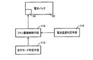
より具体的には、図10は、電子制御装置110による制御機能の要部を説明する機能ブロック線図である。図10において、走行モード判定部すなわち走行モード判定手段112は、例えばエコモードスイッチ50によりエコモードが選択されているか否かを判定する。具体的には、走行モード判定手段112は、エコモードオンSW_ONが出力されているか否かに基づいてエコモードが選択されているか否かを判断する。つまり、走行モード判定手段112は、エコモードオンSW_ONが出力されているときにはエコモードが選択されていると判定し、エコモードオンSW_ONが出力されていないときにはノーマルモードが選択されていると判定する。
電池温度判定部すなわち電池温度判定手段114は、例えば電池温度THBATが電池パック28における電力の入出力が減少する所定低温度THBATβ以下であるか否か、すなわち電池温度THBATが所定低温度THBATβを超えているか否かを判定する。
ファン駆動制御部すなわちファン駆動制御手段116は、例えば走行モード判定手段112によりノーマルモードが選択されていると判定された場合には、或いは走行モード判定手段112によりエコモードが選択されていると判定されるときに電池温度判定手段114により電池温度THBATが所定低温度THBATβ以下であると判定された場合には、例えば図7に示すようなファン回転速度マップ(すなわち図11の実線に示すようなノーマルモード時のファン回転速度マップ)から電池温度THBATに基づいてファン回転速度NFANを算出し、その算出したファン回転速度NFANが得られるように冷却ファン34を作動させる為のファン制御指令信号を出力する。
また、ファン駆動制御手段116は、例えば走行モード判定手段112によりエコモードが選択されていると判定され、且つ電池温度判定手段114により電池温度THBATが所定低温度THBATβを超えていると判定された場合には、例えば図11の破線に示すようなエコモード時のファン回転速度マップから電池温度THBATに基づいてファン回転速度NFANを算出し、その算出したファン回転速度NFANが得られるように冷却ファン34を作動させる為のファン制御指令信号を出力する。図11において、実線はノーマルモードが選択されているときに用いるノーマルモード時ファン回転速度マップであって、例えば図7に示すファン回転速度マップと同じマップである。また、図11の破線は、エコモードが選択されているときに用いるエコモード時ファン回転速度マップであって、上記ノーマルモード時ファン回転速度マップ(実線)と比較して、ファン回転速度NFANが上昇され易いように(すなわち冷却ファン34の風量Qが増大されやすいように)予め設定されているマップである。このエコモード時ファン回転速度マップ(破線)では、ノーマルモード時ファン回転速度マップ(実線)と比較して、例えばNV性能を満たす基準を緩和する分だけ、ファン回転速度NFANを上昇させる(すなわち冷却ファン34の風量Qを増大させる)ように設定されている。ここでは、ファン駆動制御手段116は、ファン回転速度マップから電池温度THBATに基づいてファン回転速度NFANを算出したが、ファン回転速度マップが車速Vを変数として設定されているときにはそのファン回転速度マップから車速Vに基づいてファン回転速度NFANを算出しても良い。
尚、エコモード時にファン回転速度NFANを上昇させる(すなわち冷却ファン34の風量Qを増大させる)ことは冷却ファン34における電力消費が増大することになるが、例えば図8に示すような電池温度THBATが所定高温度THBATαより高くなる高温度領域における電池パック28に蓄電可能な電力(例えば電動機Mが発生する回生エネルギ)の抑制分の方が上記冷却ファン34における電力消費増大よりも格段に大きいので、冷却性能を向上させたことによる上記回生エネルギの増大分からこの電力消費の増大分を差し引いても実用燃費が向上することになる。
図12は、電子制御装置110の制御作動の要部すなわちNV性能を満たしつつ電池パック28の冷却性能を確保して、電池寿命の向上と燃費性能の向上とを図る為の制御作動を説明するフローチャートであり、例えば数msec乃至数十msec程度の極めて短いサイクルタイムで繰り返し実行される。
図12において、先ず、走行モード判定手段112手段に対応するステップ(以下、ステップを省略する)S10において、例えばエコモードオンSW_ONが出力されているか否かに基づいてエコモードが選択されているか否かが判断される。このS10の判断が肯定される場合は電池温度判定手段114に対応するS20において、例えば電池温度THBATが所定低温度THBATβを超えているか否かが判定される。上記S10の判断が否定されるか或いは上記S20の判断が否定される場合はファン駆動制御手段116に対応するS30において、例えば図11の実線に示すようなノーマルモード時ファン回転速度マップから電池温度THBATに基づいてファン回転速度NFANが算出され、その算出したファン回転速度NFANが得られるように冷却ファン34を作動させる為のファン制御指令信号が出力される。一方、上記S20の判断が肯定される場合は同じくファン駆動制御手段116に対応するS40において、例えば上記ノーマルモード時ファン回転速度マップ(実線)と比較してファン回転速度NFANが上昇され易いように予め設定されている図11の破線に示すようなエコモード時ファン回転速度マップから電池温度THBATに基づいてファン回転速度NFANが算出され、その算出したファン回転速度NFANが得られるように冷却ファン34を作動させる為のファン制御指令信号が出力される。
上述のように、本実施例によれば、冷却装置として冷却ファン34を備え、冷却ファン34によって発生させる風を用いて電池(電池パック28、電池セル32)を冷却するものであり、燃費性能を優先した走行を行う為の所定の走行様式であるエコモードが選択されているときには、そのエコモードが選択されていないノーマルモードと比較して、冷却ファン34の風量Qが増大させられる(すなわちファン回転速度NFANを上昇させられる)ので、例えばエコモードが選択されたときはNV性能の向上よりも電池冷却が優先され、電池温度THBATが一層下げられることで電池パック28に蓄電可能な電力例えば電動機Mによる回生エネルギが増大させられて実用燃費を向上させることができる。また、電池温度THBATが一層下げられることで電池寿命を向上させることもできる。つまり、ユーザが燃費性能を優先した走行を望む場合にはNV性能を満たす基準を緩和して冷却性能の向上を優先しても良いという観点から、NV性能の向上の為に冷却ファン34の風量Qの増大(すなわちファン回転速度NFANの上昇)を抑制していることに対して、NV性能を満たす基準を緩和する分、冷却ファン34の風量Qを増大させて(すなわちファン回転速度NFANを上昇させて)冷却性能を向上させる。よって、NV性能を満たしつつ電池パック28の冷却性能を確保して、電池寿命の向上と燃費性能の向上とを図ることができる。
また、本実施例によれば、電池温度THBATが電池パック28における電力の入出力が減少する所定の温度(所定低温度THBATβ)以下であるときには、冷却ファン34の風量Qの増大(すなわちファン回転速度NFANの上昇)を実行しないので、例えば電池パック28の冷却性能を高めることで却って回生エネルギを減少させなければならないようなことが回避される。つまり、ユーザが燃費性能を優先した走行を望む場合(エコモードを選択した場合)に却って実用燃費が悪化してしまうことが回避される。
また、本実施例によれば、ユーザがエコモードを選択操作できるエコモードスイッチ50を備えているので、ユーザが燃費性能を優先した走行を望む場合にはNV性能の基準を緩和して冷却性能が適切に向上される。
また、本実施例によれば、燃費性能を優先した走行を行う為の所定の走行様式は、車両10の動力性能を充分引き出しつつ燃費の良い状態で運転可能なように走行を行う為の予め設定されたノーマルモードに比較して、動力性能よりも燃費性能を優先した状態で運転可能なように走行を行う為の予め設定されたエコモードである。そして、例えばエコモードが選択されているときには、冷却ファン34の風量Qが増大させられる(すなわちファン回転速度NFANを上昇させられる)ので、ノーマルモードが選択されているときと比較して、電池温度THBATが一層下げられることで実用燃費を向上させることができると共に、電池寿命を向上させることができる。
また、本実施例によれば、電池温度THBATが高い程或いは車速Vが高い程、冷却ファン34の風量Qを増大させるように(すなわちファン回転速度NFANを上昇させるように)予め設定されたファン回転速度マップを有し、エコモードが選択されているときには、そのエコモードが選択されていないノーマルモード時に用いるノーマルモード時ファン回転速度マップと比較して冷却ファン34の風量Qが増大されやすいように(すなわちファン回転速度NFANが上昇されやすいように)予め設定されているエコモード時ファン回転速度マップを用いるので、例えばエコモードが選択されているときには、ノーマルモード時と比較して、冷却ファン34の風量Qが確実に(適切に)増大させられる(すなわちファン回転速度NFANが確実に上昇させられる)。
また、本実施例によれば、電池温度THBATが所定高温度THBATαより高くなる高温度領域では、電池温度THBATが高い程、電池パック28に蓄電可能な電力を抑制するので、例えばエコモードが選択されたときに冷却ファン34の風量Qが増大させられる(すなわちファン回転速度NFANが上昇させられる)ことにより、電池温度THBATが一層下げられることで電池パック28に蓄電可能な電力例えば電動機Mによる回生エネルギが増大させられて実用燃費を確実に向上させることができる。
以上、本発明の実施例を図面に基づいて詳細に説明したが、本発明はその他の態様においても適用される。
例えば、前述の実施例では、例えば図6の一点鎖線の矢印に示すような空気の流れFである冷却ファン34によって発生させる風を各電池セル32の間の隙間Sを通して流すことにより、電池パックをその風によって直接的に冷却する構成であったが、必ずしもこの様な形態に限らなくとも本発明は適用され得る。要は、冷却ファン34によって発生させる風を用いて電池パック28を冷却するような形態であれば良い。例えば、公知のエンジンを冷却する水冷方式のように電池パック28(各電池セル32)を冷却するように構成し、その際に用いられる冷媒を冷却ファン34によって発生させる風を用いて冷却するような電池パックをその風によって間接的に冷却する形態であっても良い。また、各電池セル32の間の隙間Sを通す風自体の温度を冷却するように構成し、その風自体の温度を冷却ファン34によって発生させる風を用いて冷却する形態であっても良い。
また、前述の実施例では、冷却装置として冷却ファン34を備えていたが、これに限らず、例えばポンプやコンプレッサ等のアクチュエータの作動により直接的或いは間接的に電池パックを冷却する冷却装置であれば本発明は適用され得る。例えば、冷却装置として冷却ポンプを備え、水冷方式や空冷方式において電池パックを冷却する為の冷媒をその冷却ポンプによって循環させ、燃費性能を優先するときには、冷却ポンプによる循環流量(冷却量)を増大させるようにしても良い。このようにしても、NV性能の向上の為に冷却装置の冷却量の増大を抑制していることに対して、燃費性能を優先するときにはNV性能を満たす基準を緩和する分、冷却装置の冷却量を増大させて冷却性能を向上させられることから、NV性能を満たしつつ電池パックの冷却性能を確保して、電池寿命の向上と燃費性能の向上とを図ることができる。
また、前述の実施例では、エコモードが選択されている場合には、例えばノーマルモード時と比較して、アクセル開度Accに対する駆動力の発生を穏やかにするように制御すると共にエアコンの稼働を燃費優先の制御とすることで、実用燃費を向上させたが、必ずしもこの様な形態に限らなくとも本発明は適用され得る。例えば、エコモードが選択されている場合には、例えばノーマルモード時と比較して、アクセル開度Accに対する駆動力の発生を穏やかにするように制御するだけでも良い。また、上記の実施例は、変速機構部16が無段変速機として機能させられる場合として例示したが、本発明は、遊星歯車式自動変速機等の他の種々の変速機構部にも適用され得る。例えば、変速機構部として遊星歯車式自動変速機を採用する場合には、上記同様に、エコモード時にはノーマルモード時と比較してアクセル開度Accに対する駆動力の発生を穏やかにするように制御しても良いが、遊星歯車式自動変速機の変速制御の為の公知の変速線(変速マップ)において、エコモード時には、ノーマルモード時に比較して、アップシフトの判定がより速く為されるように、又ダウンシフトの判定がより遅く為されるように、予め設定された変速線を用いて変速制御を行うことで、実用燃費を向上させるようにしても良い。
また、前述の実施例では、エコモードスイッチ50は、押しボタンスイッチであったが、シーソー式スイッチやスライド式スイッチ等の他の種々のスイッチが用いられ得る。また、エコモードスイッチ50に替えて、例えば手動操作に因らず運転者の音声に反応してエコモードを選択可能な装置等であっても良い。要は、運転者(ユーザ)がエコモードを選択操作できる走行様式選択装置として構成されておれば本発明は適用され得る。また、この走行様式選択装置は、エコモードに加えて他の走行様式を選択操作できるように構成されていても良い。例えば、エコモードに加えて、ノーマルモードに比較して燃費性能よりも動力性能を優先した状態で運転可能なように走行を行う為の予め設定されたスポーツモード(パワーモード)を選択操作できるように構成されていても良い。
尚、上述したのはあくまでも一実施形態であり、本発明は当業者の知識に基づいて種々の変更、改良を加えた態様で実施することができる。
28:電池パック(電池、車両用電池)
34:冷却ファン(冷却装置、送風機)
50:エコモードスイッチ(走行様式選択装置)
110:電子制御装置(冷却制御装置)
F:空気の流れ(風)
Q:風量
34:冷却ファン(冷却装置、送風機)
50:エコモードスイッチ(走行様式選択装置)
110:電子制御装置(冷却制御装置)
F:空気の流れ(風)
Q:風量
Claims (8)
- 冷却装置によって電池を冷却する車両用電池の冷却制御装置であって、
燃費性能を優先するときには、該燃費性能を優先しないときと比較して、前記冷却装置の冷却量を増大させることを特徴とする車両用電池の冷却制御装置。 - 運転者が走行様式を選択操作できる走行様式選択装置を備え、
前記燃費性能を優先するときとは、前記走行様式選択装置により該燃費性能を優先した走行を行う為の所定の走行様式が選択されているときであることを特徴とする請求項1に記載の車両用電池の冷却制御装置。 - 前記冷却装置として送風機を備え、
前記送風機によって発生させる風を用いて電池を冷却するものであり、
燃費性能を優先した走行を行う為の所定の走行様式が選択されているときには、該所定の走行様式が選択されていないときと比較して、前記送風機の風量を増大させることを特徴とする請求項1に記載の車両用電池の冷却制御装置。 - 前記電池の温度が該電池における電力の入出力が減少する所定の温度以下であるときには、前記風量の増大を実行しないことを特徴とする請求項3に記載の車両用電池の冷却制御装置。
- 運転者が前記所定の走行様式を選択操作できる走行様式選択装置を備えていることを特徴とする請求項3又は4に記載の車両用電池の冷却制御装置。
- 前記所定の走行様式は、車両の動力性能を充分引き出しつつ燃費の良い状態で運転可能なように走行を行う為の予め設定されたノーマルモードに比較して、動力性能よりも燃費性能を優先した状態で運転可能なように走行を行う為の予め設定されたエコモードであることを特徴とする請求項3乃至5の何れか1項に記載の車両用電池の冷却制御装置。
- 前記電池の温度が高い程或いは車速が高い程、前記送風機の風量を増大させるように予め設定された関係を有し、
前記燃費性能を優先した走行を行う為の所定の走行様式が選択されているときには、該所定の走行様式が選択されていないときに用いる前記関係と比較して前記風量が増大されやすいように予め設定されている前記関係を用いることを特徴とする請求項3乃至6の何れか1項に記載の車両用電池の冷却制御装置。 - 前記電池の温度が高い程、該電池に蓄電可能な電力を抑制することを特徴とする請求項1乃至7の何れか1項に記載の車両用電池の冷却制御装置。
Priority Applications (1)
| Application Number | Priority Date | Filing Date | Title |
|---|---|---|---|
| PCT/JP2010/054443 WO2011114443A1 (ja) | 2010-03-16 | 2010-03-16 | 車両用電池の冷却制御装置 |
Applications Claiming Priority (1)
| Application Number | Priority Date | Filing Date | Title |
|---|---|---|---|
| PCT/JP2010/054443 WO2011114443A1 (ja) | 2010-03-16 | 2010-03-16 | 車両用電池の冷却制御装置 |
Publications (1)
| Publication Number | Publication Date |
|---|---|
| WO2011114443A1 true WO2011114443A1 (ja) | 2011-09-22 |
Family
ID=44648575
Family Applications (1)
| Application Number | Title | Priority Date | Filing Date |
|---|---|---|---|
| PCT/JP2010/054443 Ceased WO2011114443A1 (ja) | 2010-03-16 | 2010-03-16 | 車両用電池の冷却制御装置 |
Country Status (1)
| Country | Link |
|---|---|
| WO (1) | WO2011114443A1 (ja) |
Cited By (9)
| Publication number | Priority date | Publication date | Assignee | Title |
|---|---|---|---|---|
| JP2013119355A (ja) * | 2011-12-08 | 2013-06-17 | Toyota Motor Corp | 車両 |
| WO2013088553A1 (ja) * | 2011-12-15 | 2013-06-20 | トヨタ自動車株式会社 | 自動車 |
| JPWO2013088553A1 (ja) * | 2011-12-15 | 2015-04-27 | トヨタ自動車株式会社 | 自動車 |
| JP2015095911A (ja) * | 2013-11-08 | 2015-05-18 | トヨタ自動車株式会社 | 車両の電源装置 |
| US20180226704A1 (en) * | 2017-02-08 | 2018-08-09 | Kubota Corporation | Power source apparatus and working machine having the same |
| AU2020289780B2 (en) * | 2019-12-26 | 2022-03-24 | Transportation Ip Holdings, Llc | Control system and method for a vehicle system |
| JP2023099463A (ja) * | 2021-12-31 | 2023-07-13 | 現代自動車株式会社 | 電動化車両及びそのための電源管理方法 |
| US12351067B2 (en) | 2019-12-26 | 2025-07-08 | Transportation Ip Holdings, Llc | Control system and method for a vehicle system |
| US12377723B2 (en) | 2022-06-29 | 2025-08-05 | Volvo Truck Corporation | Noise management in electric heavy vehicles |
Citations (4)
| Publication number | Priority date | Publication date | Assignee | Title |
|---|---|---|---|---|
| JP2006121786A (ja) * | 2004-10-19 | 2006-05-11 | Toyota Motor Corp | 車両の駆動システム |
| JP2007012568A (ja) * | 2005-07-04 | 2007-01-18 | Toyota Motor Corp | 二次電池の制御装置 |
| JP2008278705A (ja) * | 2007-05-07 | 2008-11-13 | Toyota Motor Corp | 二次電池冷却装置 |
| JP2009247150A (ja) * | 2008-03-31 | 2009-10-22 | Honda Motor Co Ltd | 燃料電池車両 |
-
2010
- 2010-03-16 WO PCT/JP2010/054443 patent/WO2011114443A1/ja not_active Ceased
Patent Citations (4)
| Publication number | Priority date | Publication date | Assignee | Title |
|---|---|---|---|---|
| JP2006121786A (ja) * | 2004-10-19 | 2006-05-11 | Toyota Motor Corp | 車両の駆動システム |
| JP2007012568A (ja) * | 2005-07-04 | 2007-01-18 | Toyota Motor Corp | 二次電池の制御装置 |
| JP2008278705A (ja) * | 2007-05-07 | 2008-11-13 | Toyota Motor Corp | 二次電池冷却装置 |
| JP2009247150A (ja) * | 2008-03-31 | 2009-10-22 | Honda Motor Co Ltd | 燃料電池車両 |
Cited By (15)
| Publication number | Priority date | Publication date | Assignee | Title |
|---|---|---|---|---|
| JP2013119355A (ja) * | 2011-12-08 | 2013-06-17 | Toyota Motor Corp | 車両 |
| WO2013088553A1 (ja) * | 2011-12-15 | 2013-06-20 | トヨタ自動車株式会社 | 自動車 |
| JPWO2013088553A1 (ja) * | 2011-12-15 | 2015-04-27 | トヨタ自動車株式会社 | 自動車 |
| CN105705369B (zh) * | 2013-11-08 | 2018-03-09 | 丰田自动车株式会社 | 车辆和车辆的电源装置 |
| CN105705369A (zh) * | 2013-11-08 | 2016-06-22 | 丰田自动车株式会社 | 车辆和车辆的电源装置 |
| US9623757B2 (en) | 2013-11-08 | 2017-04-18 | Toyota Jidosha Kabushiki Kaisha | Vehicle and electric power supply device for vehicle |
| JP2015095911A (ja) * | 2013-11-08 | 2015-05-18 | トヨタ自動車株式会社 | 車両の電源装置 |
| US20180226704A1 (en) * | 2017-02-08 | 2018-08-09 | Kubota Corporation | Power source apparatus and working machine having the same |
| US10490869B2 (en) * | 2017-02-08 | 2019-11-26 | Kubota Corporation | Power source apparatus and working machine having the same |
| AU2020289780B2 (en) * | 2019-12-26 | 2022-03-24 | Transportation Ip Holdings, Llc | Control system and method for a vehicle system |
| US11565731B2 (en) | 2019-12-26 | 2023-01-31 | Transportation Ip Holdings, Llc | Control system and method for a vehicle system |
| AU2022204327B2 (en) * | 2019-12-26 | 2024-09-26 | Transportation Ip Holdings, Llc | Control system and method for a vehicle system |
| US12351067B2 (en) | 2019-12-26 | 2025-07-08 | Transportation Ip Holdings, Llc | Control system and method for a vehicle system |
| JP2023099463A (ja) * | 2021-12-31 | 2023-07-13 | 現代自動車株式会社 | 電動化車両及びそのための電源管理方法 |
| US12377723B2 (en) | 2022-06-29 | 2025-08-05 | Volvo Truck Corporation | Noise management in electric heavy vehicles |
Similar Documents
| Publication | Publication Date | Title |
|---|---|---|
| WO2011114443A1 (ja) | 車両用電池の冷却制御装置 | |
| KR102018474B1 (ko) | 하이브리드 자동차의 구동 장치 제어 방법, 그리고 하이브리드 자동차 | |
| JP7041398B2 (ja) | 車両駆動装置 | |
| JP5547699B2 (ja) | 車両の駆動装置 | |
| JP5110155B2 (ja) | 車両用制御装置および車両用制御方法 | |
| US7766788B2 (en) | Drive force output apparatus, method for controlling same apparatus, and vehicle | |
| JP3817516B2 (ja) | ハイブリッド車両の駆動制御装置 | |
| US8313413B2 (en) | Control device for hybrid vehicle driving device, and control method for the driving device | |
| CN100546854C (zh) | 车用驱动系统的控制设备 | |
| US8065069B2 (en) | Vehicle and control method thereof | |
| CN107428331B (zh) | 混合动力车辆的减振控制装置 | |
| CN103987602B (zh) | 混合动力车辆的控制装置 | |
| JP5958868B2 (ja) | 発電制御装置 | |
| JP5712998B2 (ja) | 車両用制御装置 | |
| US9434371B2 (en) | Control device of hybrid vehicle | |
| US20070118255A1 (en) | Control device for motor-driven vehicle | |
| CN105593090B (zh) | 混合动力车辆的控制装置 | |
| CN103958260A (zh) | 具有增程器的电动车辆 | |
| JPWO2016174920A1 (ja) | 車両の表示回転数制御装置 | |
| JP4229105B2 (ja) | ハイブリッド車およびその制御方法 | |
| JP7235173B2 (ja) | ハイブリッド車の制御装置 | |
| JP2012239282A (ja) | 車両およびその制御方法 | |
| JP2019131151A (ja) | ハイブリッド車両の制御装置 | |
| JP6607021B2 (ja) | ハイブリッド車両の発電制御装置 | |
| JP4123691B2 (ja) | 燃料電池を用いたハイブリッド式駆動源を備える移動体 |
Legal Events
| Date | Code | Title | Description |
|---|---|---|---|
| 121 | Ep: the epo has been informed by wipo that ep was designated in this application |
Ref document number: 10847859 Country of ref document: EP Kind code of ref document: A1 |
|
| DPE1 | Request for preliminary examination filed after expiration of 19th month from priority date (pct application filed from 20040101) | ||
| NENP | Non-entry into the national phase |
Ref country code: DE |
|
| 122 | Ep: pct application non-entry in european phase |
Ref document number: 10847859 Country of ref document: EP Kind code of ref document: A1 |
|
| NENP | Non-entry into the national phase |
Ref country code: JP |