WO2011108677A1 - 炭素繊維強化プラスチック成形体 - Google Patents
炭素繊維強化プラスチック成形体 Download PDFInfo
- Publication number
- WO2011108677A1 WO2011108677A1 PCT/JP2011/054993 JP2011054993W WO2011108677A1 WO 2011108677 A1 WO2011108677 A1 WO 2011108677A1 JP 2011054993 W JP2011054993 W JP 2011054993W WO 2011108677 A1 WO2011108677 A1 WO 2011108677A1
- Authority
- WO
- WIPO (PCT)
- Prior art keywords
- carbon fiber
- reinforced plastic
- fiber reinforced
- layer
- resin
- Prior art date
- Legal status (The legal status is an assumption and is not a legal conclusion. Google has not performed a legal analysis and makes no representation as to the accuracy of the status listed.)
- Ceased
Links
Images




Classifications
-
- B—PERFORMING OPERATIONS; TRANSPORTING
- B32—LAYERED PRODUCTS
- B32B—LAYERED PRODUCTS, i.e. PRODUCTS BUILT-UP OF STRATA OF FLAT OR NON-FLAT, e.g. CELLULAR OR HONEYCOMB, FORM
- B32B27/00—Layered products comprising a layer of synthetic resin
- B32B27/12—Layered products comprising a layer of synthetic resin next to a fibrous or filamentary layer
-
- F—MECHANICAL ENGINEERING; LIGHTING; HEATING; WEAPONS; BLASTING
- F16—ENGINEERING ELEMENTS AND UNITS; GENERAL MEASURES FOR PRODUCING AND MAINTAINING EFFECTIVE FUNCTIONING OF MACHINES OR INSTALLATIONS; THERMAL INSULATION IN GENERAL
- F16F—SPRINGS; SHOCK-ABSORBERS; MEANS FOR DAMPING VIBRATION
- F16F9/00—Springs, vibration-dampers, shock-absorbers, or similarly-constructed movement-dampers using a fluid or the equivalent as damping medium
- F16F9/30—Springs, vibration-dampers, shock-absorbers, or similarly-constructed movement-dampers using a fluid or the equivalent as damping medium with solid or semi-solid material, e.g. pasty masses, as damping medium
- F16F9/306—Springs, vibration-dampers, shock-absorbers, or similarly-constructed movement-dampers using a fluid or the equivalent as damping medium with solid or semi-solid material, e.g. pasty masses, as damping medium of the constrained layer type, i.e. comprising one or more constrained viscoelastic layers
-
- B—PERFORMING OPERATIONS; TRANSPORTING
- B32—LAYERED PRODUCTS
- B32B—LAYERED PRODUCTS, i.e. PRODUCTS BUILT-UP OF STRATA OF FLAT OR NON-FLAT, e.g. CELLULAR OR HONEYCOMB, FORM
- B32B5/00—Layered products characterised by the non- homogeneity or physical structure, i.e. comprising a fibrous, filamentary, particulate or foam layer; Layered products characterised by having a layer differing constitutionally or physically in different parts
- B32B5/02—Layered products characterised by the non- homogeneity or physical structure, i.e. comprising a fibrous, filamentary, particulate or foam layer; Layered products characterised by having a layer differing constitutionally or physically in different parts characterised by structural features of a fibrous or filamentary layer
- B32B5/12—Layered products characterised by the non- homogeneity or physical structure, i.e. comprising a fibrous, filamentary, particulate or foam layer; Layered products characterised by having a layer differing constitutionally or physically in different parts characterised by structural features of a fibrous or filamentary layer characterised by the relative arrangement of fibres or filaments of different layers, e.g. the fibres or filaments being parallel or perpendicular to each other
-
- B—PERFORMING OPERATIONS; TRANSPORTING
- B32—LAYERED PRODUCTS
- B32B—LAYERED PRODUCTS, i.e. PRODUCTS BUILT-UP OF STRATA OF FLAT OR NON-FLAT, e.g. CELLULAR OR HONEYCOMB, FORM
- B32B5/00—Layered products characterised by the non- homogeneity or physical structure, i.e. comprising a fibrous, filamentary, particulate or foam layer; Layered products characterised by having a layer differing constitutionally or physically in different parts
- B32B5/14—Layered products characterised by the non- homogeneity or physical structure, i.e. comprising a fibrous, filamentary, particulate or foam layer; Layered products characterised by having a layer differing constitutionally or physically in different parts characterised by a layer differing constitutionally or physically in different parts, e.g. denser near its faces
- B32B5/142—Variation across the area of the layer
-
- B—PERFORMING OPERATIONS; TRANSPORTING
- B32—LAYERED PRODUCTS
- B32B—LAYERED PRODUCTS, i.e. PRODUCTS BUILT-UP OF STRATA OF FLAT OR NON-FLAT, e.g. CELLULAR OR HONEYCOMB, FORM
- B32B5/00—Layered products characterised by the non- homogeneity or physical structure, i.e. comprising a fibrous, filamentary, particulate or foam layer; Layered products characterised by having a layer differing constitutionally or physically in different parts
- B32B5/22—Layered products characterised by the non- homogeneity or physical structure, i.e. comprising a fibrous, filamentary, particulate or foam layer; Layered products characterised by having a layer differing constitutionally or physically in different parts characterised by the presence of two or more layers which are next to each other and are fibrous, filamentary, formed of particles or foamed
- B32B5/24—Layered products characterised by the non- homogeneity or physical structure, i.e. comprising a fibrous, filamentary, particulate or foam layer; Layered products characterised by having a layer differing constitutionally or physically in different parts characterised by the presence of two or more layers which are next to each other and are fibrous, filamentary, formed of particles or foamed one layer being a fibrous or filamentary layer
- B32B5/26—Layered products characterised by the non- homogeneity or physical structure, i.e. comprising a fibrous, filamentary, particulate or foam layer; Layered products characterised by having a layer differing constitutionally or physically in different parts characterised by the presence of two or more layers which are next to each other and are fibrous, filamentary, formed of particles or foamed one layer being a fibrous or filamentary layer another layer next to it also being fibrous or filamentary
-
- B—PERFORMING OPERATIONS; TRANSPORTING
- B32—LAYERED PRODUCTS
- B32B—LAYERED PRODUCTS, i.e. PRODUCTS BUILT-UP OF STRATA OF FLAT OR NON-FLAT, e.g. CELLULAR OR HONEYCOMB, FORM
- B32B2260/00—Layered product comprising an impregnated, embedded, or bonded layer wherein the layer comprises an impregnation, embedding, or binder material
- B32B2260/02—Composition of the impregnated, bonded or embedded layer
- B32B2260/021—Fibrous or filamentary layer
- B32B2260/023—Two or more layers
-
- B—PERFORMING OPERATIONS; TRANSPORTING
- B32—LAYERED PRODUCTS
- B32B—LAYERED PRODUCTS, i.e. PRODUCTS BUILT-UP OF STRATA OF FLAT OR NON-FLAT, e.g. CELLULAR OR HONEYCOMB, FORM
- B32B2260/00—Layered product comprising an impregnated, embedded, or bonded layer wherein the layer comprises an impregnation, embedding, or binder material
- B32B2260/04—Impregnation, embedding, or binder material
- B32B2260/046—Synthetic resin
-
- B—PERFORMING OPERATIONS; TRANSPORTING
- B32—LAYERED PRODUCTS
- B32B—LAYERED PRODUCTS, i.e. PRODUCTS BUILT-UP OF STRATA OF FLAT OR NON-FLAT, e.g. CELLULAR OR HONEYCOMB, FORM
- B32B2262/00—Composition or structural features of fibres which form a fibrous or filamentary layer or are present as additives
- B32B2262/10—Inorganic fibres
- B32B2262/106—Carbon fibres, e.g. graphite fibres
-
- B—PERFORMING OPERATIONS; TRANSPORTING
- B32—LAYERED PRODUCTS
- B32B—LAYERED PRODUCTS, i.e. PRODUCTS BUILT-UP OF STRATA OF FLAT OR NON-FLAT, e.g. CELLULAR OR HONEYCOMB, FORM
- B32B2307/00—Properties of the layers or laminate
- B32B2307/50—Properties of the layers or laminate having particular mechanical properties
- B32B2307/51—Elastic
-
- B—PERFORMING OPERATIONS; TRANSPORTING
- B32—LAYERED PRODUCTS
- B32B—LAYERED PRODUCTS, i.e. PRODUCTS BUILT-UP OF STRATA OF FLAT OR NON-FLAT, e.g. CELLULAR OR HONEYCOMB, FORM
- B32B2307/00—Properties of the layers or laminate
- B32B2307/50—Properties of the layers or laminate having particular mechanical properties
- B32B2307/546—Flexural strength; Flexion stiffness
-
- B—PERFORMING OPERATIONS; TRANSPORTING
- B32—LAYERED PRODUCTS
- B32B—LAYERED PRODUCTS, i.e. PRODUCTS BUILT-UP OF STRATA OF FLAT OR NON-FLAT, e.g. CELLULAR OR HONEYCOMB, FORM
- B32B2307/00—Properties of the layers or laminate
- B32B2307/50—Properties of the layers or laminate having particular mechanical properties
- B32B2307/56—Damping, energy absorption
-
- F—MECHANICAL ENGINEERING; LIGHTING; HEATING; WEAPONS; BLASTING
- F16—ENGINEERING ELEMENTS AND UNITS; GENERAL MEASURES FOR PRODUCING AND MAINTAINING EFFECTIVE FUNCTIONING OF MACHINES OR INSTALLATIONS; THERMAL INSULATION IN GENERAL
- F16F—SPRINGS; SHOCK-ABSORBERS; MEANS FOR DAMPING VIBRATION
- F16F2224/00—Materials; Material properties
- F16F2224/02—Materials; Material properties solids
- F16F2224/0241—Fibre-reinforced plastics [FRP]
-
- Y—GENERAL TAGGING OF NEW TECHNOLOGICAL DEVELOPMENTS; GENERAL TAGGING OF CROSS-SECTIONAL TECHNOLOGIES SPANNING OVER SEVERAL SECTIONS OF THE IPC; TECHNICAL SUBJECTS COVERED BY FORMER USPC CROSS-REFERENCE ART COLLECTIONS [XRACs] AND DIGESTS
- Y10—TECHNICAL SUBJECTS COVERED BY FORMER USPC
- Y10T—TECHNICAL SUBJECTS COVERED BY FORMER US CLASSIFICATION
- Y10T428/00—Stock material or miscellaneous articles
- Y10T428/24—Structurally defined web or sheet [e.g., overall dimension, etc.]
- Y10T428/24744—Longitudinal or transverse tubular cavity or cell
-
- Y—GENERAL TAGGING OF NEW TECHNOLOGICAL DEVELOPMENTS; GENERAL TAGGING OF CROSS-SECTIONAL TECHNOLOGIES SPANNING OVER SEVERAL SECTIONS OF THE IPC; TECHNICAL SUBJECTS COVERED BY FORMER USPC CROSS-REFERENCE ART COLLECTIONS [XRACs] AND DIGESTS
- Y10—TECHNICAL SUBJECTS COVERED BY FORMER USPC
- Y10T—TECHNICAL SUBJECTS COVERED BY FORMER US CLASSIFICATION
- Y10T428/00—Stock material or miscellaneous articles
- Y10T428/31504—Composite [nonstructural laminate]
Definitions
- the present invention relates to a carbon fiber reinforced plastic molded body.
- Carbon fiber reinforced plastic molded products are lighter and more rigid than metals such as aluminum and iron, and have recently attracted attention as new materials to replace metals.
- improvement in vibration damping is desired. Therefore, a carbon fiber reinforced plastic molded body is proposed in which a damping elastic layer made of a viscoelastic material such as polyimide is disposed between carbon fiber reinforced plastic layers laminated to each other (see, for example, Patent Document 1). .
- the carbon fiber reinforced plastic molded body as described above may be applied to industrial parts as a part of a support member, for example.
- the carbon fiber reinforced plastic molded body in addition to improving the vibration damping property, it is required to ensure a certain bending rigidity.
- the carbon fiber reinforced plastic molded body it is required to improve the bending rigidity while ensuring a certain vibration damping property.
- the present invention provides a carbon fiber reinforced plastic molded body capable of improving vibration damping while ensuring bending rigidity, and a carbon fiber reinforced plastic molding capable of improving bending rigidity while ensuring vibration damping.
- the challenge is to provide a body.
- a carbon fiber reinforced plastic molded body includes a long first and second carbon fiber reinforced plastic layers laminated together, a first carbon fiber reinforced plastic layer, and a first carbon fiber reinforced plastic layer.
- a damping elastic layer disposed between the two carbon fiber reinforced plastic layers, and the damping elastic layer has a plurality of viscoelastic resin regions made of viscoelastic resin,
- the first and second carbon fiber reinforced plastic layers are arranged so as to be separated from each other along the longitudinal direction of the first and second carbon fiber reinforced plastic layers.
- a high-rigidity resin region made of a rigid resin is provided.
- this carbon fiber reinforced plastic molded body since the vibration damping elastic layer having the viscoelastic resin region is disposed between the first carbon fiber reinforced plastic layer and the second carbon fiber reinforced plastic layer, the vibration damping property is improved. Is improved. Further, in this carbon fiber reinforced plastic molded body, a plurality of viscoelastic resin regions are arranged apart from each other along the longitudinal direction of the first and second carbon fiber reinforced plastic layers, and these viscoelastic resin regions are arranged. Since a high-rigidity resin region having a relatively high rigidity is provided between the first and second carbon fiber reinforced plastic layers, bending rigidity along the longitudinal direction of the first and second carbon fiber reinforced plastic layers is ensured.
- the surfaces facing each other across the high-rigidity resin region are substantially parallel. According to this configuration, the vibration damping property and the bending stiffness distribution are substantially uniform along the direction in which the opposing surfaces extend across the high-rigidity resin region.
- the high-rigidity resin is the same as the resin constituting the first and second carbon fiber-reinforced plastic layers, and the high-rigidity resin region is the first and second It is preferably formed integrally with the carbon fiber reinforced plastic layer. According to this configuration, when the first and second carbon fiber reinforced plastic layers and the vibration-damping elastic layer are integrally formed, the resin constituting the first and second carbon fiber reinforced plastic layers can be easily formed. A highly rigid resin region can be formed.
- the carbon fiber reinforced plastic molding which concerns on this invention is the 1st and 2nd carbon fiber reinforced plastic layer laminated
- a damping elastic layer disposed between the carbon fiber reinforced plastic layer and the damping elastic layer made of a material including a viscoelastic resin and a fibrous material kneaded in the viscoelastic resin, and a fiber.
- the material is characterized by having a rigidity higher than that of the viscoelastic resin.
- a fibrous material kneaded with a viscoelastic resin and a viscoelastic resin between the first carbon fiber reinforced plastic layer and the second carbon fiber reinforced plastic layer and having a relatively high rigidity. Since the vibration-damping elastic layer made of the material containing is disposed, the bending rigidity can be improved while ensuring the vibration-damping property.
- the first and second carbon fiber reinforced plastic layers are elongated, and the vibration-damping elastic layers are the first and second carbon fiber reinforced plastics. It is preferably divided into a plurality of regions by a plurality of gaps arranged along the longitudinal direction of the layer. According to this configuration, the plurality of regions of the damping elastic layer are arranged so as to be separated from each other along the longitudinal direction of the first and second carbon fiber reinforced plastic layers. The bending rigidity along the longitudinal direction of the carbon fiber reinforced plastic layer can be improved.
- the surfaces facing each other with a gap between them are substantially parallel in adjacent regions. According to this configuration, it is possible to make the distribution of vibration damping properties and bending rigidity substantially uniform along the direction in which the surfaces facing each other across the gap extend.
- the fibrous substance is preferably at least one of carbon nanotubes, ketjen black, short glass fibers, and short carbon fibers. According to this configuration, it is possible to suitably improve the bending rigidity using carbon nanotubes, ketjen black, short glass fibers, and short carbon fibers.
- a carbon fiber reinforced plastic molded body capable of improving vibration damping while ensuring bending rigidity
- a carbon fiber reinforced plastic molding capable of improving bending rigidity while ensuring vibration damping.
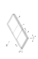
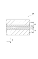
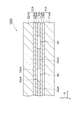
- FIG. 1 is a perspective view of a first embodiment of a carbon fiber reinforced plastic molded body according to the present invention.
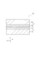
- FIG. 2 is a partial sectional view taken along line II-II in FIG.
- FIG. 3 is a partial sectional view taken along line III-III in FIG. It is a perspective view of 2nd Embodiment of the carbon fiber reinforced plastic molding which concerns on this invention.
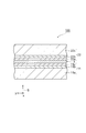
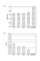
- FIG. 5 is a partial sectional view taken along line VV in FIG. 4. It is a perspective view of the carbon fiber reinforced plastic molding which concerns on a comparative example. It is a graph which shows the measurement result of the bending rigidity and the damping property of the carbon fiber reinforced plastic molding which concerns on an Example and a comparative example.
- a carbon fiber reinforced plastic (hereinafter referred to as “CFPR: Carbon Fiber Reinforced Plastics”) molded body 10 includes CFRP layers (laminated with each other along the z-axis direction of the orthogonal coordinate system S) ( A first carbon fiber reinforced plastic layer) 1 and a CFRP layer (second carbon fiber reinforced plastic layer) 2, and a damping elastic layer 3 disposed between the CFRP layer 1 and the CFRP layer 2. Yes.
- CFRP molded body 10 can be used for industrial parts such as a robot hand.
- the CFRP layers 1 and 2 have a long plate shape extending along the x-axis direction of the orthogonal coordinate system S, and are impregnated and cured in a plurality of carbon fiber layers made of carbon fibers and these carbon fiber layers. And a matrix resin (for example, epoxy resin).
- a matrix resin for example, epoxy resin
- the CFRP layer 1 includes an outer layer 1a and an inner layer 1b that are sequentially stacked along the z-axis direction.
- the outer layer 1a can include, for example, five carbon fiber layers arranged so that the orientation direction of the carbon fibers is 0 degree.
- the inner layer 1b can include, for example, one carbon fiber layer arranged so that the orientation direction of the carbon fibers is 90 degrees.
- the angle here is an angle with respect to the x-axis direction.
- the CFRP layer 2 includes an inner layer 2a and an outer layer 2b that are sequentially stacked along the z-axis direction.
- the inner layer 2a can include, for example, one carbon fiber layer disposed so that the orientation direction of the carbon fibers is 90 degrees.
- the outer layer 2b can include, for example, five carbon fiber layers arranged so that the orientation direction of the carbon fibers is 0 degree.
- the damping elastic layer 3 has a viscoelastic resin region 3a and a viscoelastic resin region 3b arranged so as to be separated from each other along the longitudinal direction (x-axis direction) of the CFRP layers 1 and 2.
- the viscoelastic resin regions 3a and 3b are made of viscoelastic resin.
- the viscoelastic resin is a resin having rigidity lower than that of the matrix resin constituting the CFRP layers 1 and 2, and can be a viscoelastic material (flexible resin material) such as rubber or elastomer.
- the viscoelastic material preferably has a storage elastic modulus at 25 ° C.
- the storage elastic modulus of the viscoelastic material is 2500 MPa or less, sufficient vibration damping performance can be obtained. If the storage elastic modulus is 0.1 MPa or more, there is little decrease in the rigidity of the CFRP molded body 10, and the robot hand or robot arm The performance required for industrial parts such as the above can be satisfied.
- the viscoelastic material is converted from the carbon fiber prepreg to CFRP by thermosetting, it is preferable that the viscoelastic material is stable against the heat generated at that time.
- the viscoelastic material is preferably a material having excellent adhesion to the matrix resin of the CFRP layers 1 and 2.
- the viscoelastic materials constituting the viscoelastic resin regions 3a and 3b are, for example, styrene-butadiene rubber (SBR), chloroprene rubber (CR), butyl rubber (IIR), nitrile rubber (NBR), and ethylene.
- SBR styrene-butadiene rubber
- CR chloroprene rubber
- IIR butyl rubber
- NBR nitrile rubber
- ethylene ethylene
- the material can be made more flexible than CFRP.
- a high-rigidity resin region 4 made of a high-rigidity resin (for example, epoxy resin) having higher rigidity than that of the viscoelastic resin is provided.
- the high-rigidity resin region 4 is disposed without a gap in a region between the viscoelastic resin region 3a and the viscoelastic resin region 3b.
- the surfaces 3c and 3d facing each other with the high-rigidity resin region 4 interposed therebetween extend along the y-axis direction of the orthogonal coordinate system S and are substantially parallel to each other.
- Such a vibration-damping elastic layer 3 is formed, for example, by pouring a solution of a viscoelastic resin into a sheet-shaped mold, drying it, heating and compressing it with a hot press machine, and then cutting the central part in the longitudinal direction. Can be produced.
- the CFRP molded body 10 includes, for example, the damping elastic layer 3 produced as described above between the prepreg laminate for the CFRP layer 1 and the prepreg laminate for the CFRP layer 2. Then, the CFRP layer 1, the damping elastic layer 3, and the CFRP layer 2 are integrally formed by heating and compression. At this time, the high-rigidity resin region 4 can be formed by the matrix resin constituting the CFRP layers 1 and 2. In this case, the high-rigidity resin region 4 is formed integrally with the CFRP layers 1 and 2.
- the damping elastic layer 3 having the viscoelastic resin regions 3a and 3b is disposed between the CFRP layer 1 and the CFRP layer 2, the damping performance is improved.
- viscoelastic resin regions 3a and 3b are arranged apart from each other along the x-axis direction, and the rigidity is relatively high between the viscoelastic resin regions 3a and 3b. Since the resin region 4 is provided, bending rigidity along the x-axis direction is ensured.
- the surfaces 3c and 3d facing each other with the high-rigidity resin region 4 interposed therebetween are substantially parallel to each other.
- the distribution of vibration damping properties and bending stiffness is substantially uniform.
- the CFRP molded body 100 is different from the CFRP molded body 10 according to the first embodiment in place of the CFRP layer 1 and a CFRP layer (first carbon fiber reinforced plastic layer) 11. And a point that a CFRP layer (second carbon fiber reinforced plastic layer) 22 is provided instead of the CFRP layer 2.
- the CFRP layers 11 and 22 have a long plate shape extending along the x-axis direction, and a plurality of carbon fiber layers made of carbon fibers and a matrix resin impregnated and cured in these carbon fiber layers (for example, Epoxy resin).
- the CFRP layer 11 includes an outer layer 11a, an intermediate layer 11b, and an inner layer 11c that are sequentially stacked along the z-axis direction.
- the outer layer 11a can include, for example, four carbon fiber layers arranged so that the orientation direction of the carbon fibers is 0 degree.
- the intermediate layer 11b can include, for example, one carbon fiber layer disposed so that the orientation direction of the carbon fibers is 90 degrees.
- the inner layer 11c can include, for example, one carbon fiber layer disposed so that the orientation direction of the carbon fibers is 0 degree.
- the angle here is an angle with respect to the x-axis direction.
- the CFRP layer 22 includes an inner layer 22a, an intermediate layer 22b, and an outer layer 22c that are sequentially stacked along the z-axis direction.
- the inner layer 22a can include, for example, one carbon fiber layer disposed so that the orientation direction of the carbon fibers is 0 degree.
- the intermediate layer 22b can include, for example, one carbon fiber layer disposed so that the orientation direction of the carbon fibers is 90 degrees.
- the outer layer 22c can include, for example, four carbon fiber layers arranged so that the orientation direction of the carbon fibers becomes zero.
- vibration damping elastic layer 3 having the viscoelastic resin regions 3a and 3b is disposed between the CFRP layer 11 and the CFRP layer 22, vibration damping performance is improved. Be improved.
- viscoelastic resin regions 3a and 3b are arranged apart from each other along the x-axis direction, and a high rigidity resin region 4 having relatively high rigidity is provided between these viscoelastic resin regions 3a and 3b. Therefore, bending rigidity along the x-axis direction is ensured.
- the damping elastic layer 3 has two viscoelastic resin regions 3a and 3b.
- the present invention is not limited to this, and it may have three or more viscoelastic resin regions arranged so as to be separated from each other along the x-axis direction.
- test piece A1 corresponding to the CFRP molded body 10 and a test piece A2 corresponding to the CFRP molded body 100 were configured as follows.
- Granock prepreg (Granock XN-60 manufactured by Nippon Graphite Fiber Co., Ltd. (tensile elastic modulus: 620 GPa, carbon fiber basis weight: 125 g / m 2) , matrix resin content: 32 wt. %, Thickness of one layer: 0.11 mm), the same applies hereinafter), and one layer of granock prepreg is laminated thereon so that the orientation direction of the carbon fiber is 90 degrees. A prepreg laminate was obtained. Also, one layer of granock prepreg is arranged so that the orientation direction of the carbon fiber is 90 degrees, and five layers of granock prepreg are laminated thereon so that the orientation direction of the carbon fiber is 0 degree. A prepreg laminate was obtained.
- a polyurethane resin (Diaplex Co., Ltd. Diary (MS4510), the same applies hereinafter) solution was poured into a sheet mold and dried, and then heated and compressed at 150 ° C. for 1 hour using a hot press machine. Later, the damping elastic layer 3 having a thickness of 0.15 mm was obtained by cutting off the central portion in the longitudinal direction. At this time, the width of the part to be cut was 10 mm. Then, the first prepreg laminate, the vibration-damping elastic layer 3, and the second prepreg laminate are laminated in order, and heated and compressed at 130 ° C.
- a polyurethane resin Diaplex Co., Ltd. Diary (MS4510), the same applies hereinafter
- granock prepreg Four layers of granock prepreg are laminated so that the orientation direction of the carbon fiber is 0 degree, and one layer of granock prepreg is laminated thereon so that the orientation direction of the carbon fiber is 90 degrees. One more layer of granock prepreg was laminated so that the orientation direction of the carbon fiber was 0 degree to obtain a third prepreg laminate. Also, one layer of granock prepreg is disposed so that the orientation direction of the carbon fiber is 0 degree, and one layer of granock prepreg is laminated thereon so that the orientation direction of the carbon fiber is 90 degrees. Further, four layers of granock prepregs were laminated so that the orientation direction of the carbon fibers was 0 degree to obtain a fourth prepreg laminate.
- the polyurethane resin solution is poured into a sheet-shaped mold, dried, heated and compressed at 150 ° C. for 1 hour by a hot press machine, and then the central part in the longitudinal direction is cut off to obtain a thickness.
- a vibration-damping elastic layer 3 of 0.1 mm was obtained.
- the width of the part to be cut was 10 mm.
- the third prepreg laminate, the damping elastic layer 3 and the fourth prepreg laminate are laminated in order, heated and compressed at 130 ° C. for 1 hour 30 minutes, and these are integrally molded, and CFRP A test piece A2 composed of the layer 11, the damping elastic layer 3, and the CFRP layer 22 was obtained.
- the material of the high-rigidity resin region 4 was an epoxy resin.
- the comparative test piece B1 is different from the test piece A1 in that a damping elastic layer 7 is provided instead of the damping elastic layer 3.
- the vibration-damping elastic layer 7 is composed of a single region having a thickness of 0.1 mm, and the material thereof is a polyurethane resin.
- the comparative test piece B2 is different from the test piece A2 in that the vibration-damping elastic layer 7 is provided instead of the vibration-damping elastic layer 3.
- test pieces A1 and A2 and comparative test pieces B1 and B2 were all about 45 mm long, about 5 mm wide, and about 1.4 mm to 1.5 mm thick.
- test pieces A1, A2 and comparative test pieces B1, B2 are controlled by a three-point bending vibration mode in the longitudinal direction.
- Storage modulus (elastic component) E ′
- loss storage modulus (viscous component) E ′′
- the three-point bending vibration mode is a measurement method for measuring viscoelastic behavior by clamping both end portions in the longitudinal direction and applying vibration to the central portion in each test piece.
- FIG. 7A shows the bending elastic modulus retention rate (E ′ / E ′ CFRP ) at 25 ° C. of each test piece.
- E ′ CFRP is a storage elastic modulus of a CFRP molded body having no vibration damping elastic layer (consisting only of the CFRP layer 1 and the CFRP layer 2).
- FIG. 7B shows tan ⁇ at 25 ° C. of each test piece. 7A and 7B, A1 shows the measured value of the test piece A1, A2 shows the measured value of the test piece A2, and B1 shows the measured value of the comparative test piece B1. , B2 indicates the measured value of the comparative test piece B2.
- Baseline indicates a measured value of a CFRP molded body having no vibration damping elastic layer.
- the elastic modulus retention ratio (E ′ / E ′ CFRP ) is a value serving as an index of bending stiffness, and the larger this value, the higher the bending stiffness.
- tan ⁇ is a value that serves as an index of damping performance, and the larger this value, the higher the damping performance.
- tan ⁇ of the test piece A1 was 0.102
- tan ⁇ of the comparative test piece B1 was 0.07.
- tan ⁇ of the test piece A2 was 0.074
- tan ⁇ of the comparative test piece B2 was 0.044. From this, it was found that according to the test piece A1 and the test piece A2, the vibration damping properties are improved as compared with the comparative test piece B1 and the specific test piece B2.
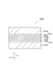
- a carbon fiber reinforced plastic (hereinafter referred to as “CFRP: Carbon Fiber Reinforced Plastics”) molded body 10 ⁇ / b> A includes CFRP layers (laminated with each other along the z-axis direction of the orthogonal coordinate system S) ( A first carbon fiber reinforced plastic layer) 1A and a CFRP layer (second carbon fiber reinforced plastic layer) 2A, and a damping elastic layer 3A disposed between the CFRP layer 1A and the CFRP layer 2A. Yes.
- CFRP molded body 10A can be used for industrial parts such as a robot hand, for example.
- the CFRP layers 1A and 2A have a long plate shape extending along the x-axis direction of the orthogonal coordinate system S, and are impregnated and cured with a plurality of carbon fiber layers made of carbon fibers and these carbon fiber layers. And a matrix resin (for example, epoxy resin).
- a matrix resin for example, epoxy resin
- the CFRP layer 1A includes an outer layer 1aA and an inner layer 1bA that are sequentially stacked along the z-axis direction.
- the outer layer 1aA can include, for example, five carbon fiber layers arranged so that the orientation direction of the carbon fibers is 0 degree.
- the inner layer 1bA can include, for example, one carbon fiber layer disposed so that the orientation direction of the carbon fibers is 90 degrees.
- the angle here is an angle with respect to the x-axis direction.
- the CFRP layer 2A includes an inner layer 2aA and an outer layer 2bA that are sequentially stacked along the z-axis direction.
- the inner layer 2aA can include, for example, one carbon fiber layer disposed so that the orientation direction of the carbon fibers is 90 degrees.
- the outer layer 2bA can include, for example, five carbon fiber layers arranged so that the orientation direction of the carbon fibers is 0 degree.
- the damping elastic layer 3A is made of a material including a viscoelastic resin and a fibrous material kneaded in the viscoelastic resin.
- the viscoelastic resin is a resin having rigidity lower than that of the matrix resin constituting the CFRP layers 1A and 2A, and can be a viscoelastic material (flexible resin material) such as rubber or elastomer.
- the viscoelastic material preferably has a storage elastic modulus at 25 ° C. in the range of 0.1 MPa to 2500 MPa, more preferably in the range of 0.1 MPa to 250 MPa, and in the range of 0.1 MPa to 25 MPa.
- the storage elastic modulus of the viscoelastic material is 2500 MPa or less, sufficient vibration damping performance can be obtained. If the storage elastic modulus is 0.1 MPa or more, there is little decrease in the rigidity of the CFRP molded body 10A. The performance required for industrial parts such as the above can be satisfied.
- the viscoelastic material is converted from the carbon fiber prepreg to CFRP by thermosetting, it is preferable that the viscoelastic material is stable against the heat generated at that time.
- the viscoelastic material is preferably a material having excellent adhesion to the matrix resin of the CFRP layers 1A and 2A.
- the viscoelastic materials constituting the viscoelastic resin regions 3aA and 3bA are, for example, styrene-butadiene rubber (SBR), chloroprene rubber (CR), butyl rubber (IIR), nitrile rubber (NBR), and ethylene.
- SBR styrene-butadiene rubber
- CR chloroprene rubber
- IIR butyl rubber
- NBR nitrile rubber
- ethylene ethylene
- the material can be made more flexible than CFRP.
- the fibrous substance has a higher rigidity than that of the viscoelastic resin, and can be, for example, at least one of carbon nanotubes, ketjen black, short glass fibers, and short carbon fibers.
- the carbon nanotubes can have a Young's modulus in the fiber longitudinal direction in the range of, for example, 500 GPa to 10,000 GPa.
- the short glass fiber can have a Young's modulus in the fiber longitudinal direction in the range of, for example, 60 GPa or more and 90 GPa or less.
- the short carbon fiber can have a Young's modulus in the longitudinal direction of the fiber in the range of, for example, 50 GPa or more and 1000 GPa or less.
- the length of these fibrous substances can be set in the range of 1 ⁇ m to 6 mm, for example. If the length of the fibrous substance is 1 ⁇ m or more, the shearing force exerted on the viscoelastic resin by the fibrous substance becomes relatively large, so that the rigidity of the CFRP molded body 10A can be improved.
- the storage elastic modulus of the damping elastic layer 3A does not become too high, and sufficient damping performance is obtained.
- the aspect ratio obtained by dividing the length of the fibrous substance by the diameter of the fibrous substance is preferably in the range of 5 to 600, and more preferably in the range of 5 to 300.
- the aspect ratio is 5 or more, entanglement between the fibrous materials is likely to occur, so that the rigidity of the CFRP molded body 10A can be improved. If the aspect ratio is 600 or less, the fibrous materials are kneaded into the viscoelastic resin. In doing so, the fibrous material can be dispersed relatively uniformly in the viscoelastic resin.
- the kneading ratio of the fibrous substance to the viscoelastic resin can be set in the range of 0.1 wt% to 30 wt%, for example. If the kneading ratio of the fibrous substance to the viscoelastic resin is 0.1% by weight or more, the effect of improving the rigidity of the CFRP molded body 10A is relatively large, and if it is 30% by weight or less, sufficient vibration damping performance is obtained. can get.
- Such a vibration-damping elastic layer 3A is obtained, for example, by adding a fibrous substance to a solution of a viscoelastic resin and stirring it, then pouring it into a sheet-shaped mold, drying it, and heating and compressing it with a hot press. Produced.
- the damping elastic layer 3A produced as described above is disposed between the prepreg laminate for the CFRP layer 1A and the prepreg laminate for the CFRP layer 2A. Then, the CFRP layer 1A, the vibration damping elastic layer 3A, and the CFRP layer 2A are integrally formed by heating and compression.
- the control is made of a material including a viscoelastic resin and a fibrous material kneaded in the viscoelastic resin and having a relatively high rigidity between the CFRP layer 1A and the CFRP layer 2A. Since the vibration elastic layer 3A is disposed, it is possible to improve the bending rigidity while ensuring the vibration damping property.
- the bending rigidity can be suitably improved by using at least one of carbon nanotubes, ketjen black, short glass fibers, and short carbon fibers as the fibrous material.
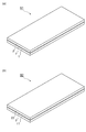
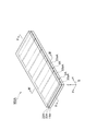
- a CFRP molded body 100A includes a CFRP layer (first carbon fiber reinforced plastic layer) 11A and a CFRP layer (carbon fiber reinforced plastic layer) 22A laminated together along the z-axis direction. And a vibration-damping elastic layer 33A disposed between the CFRP layer 11A and the CFRP layer 22A.
- the CFRP layers 11A and 22A have a long plate shape extending along the x-axis direction, a plurality of carbon fiber layers made of carbon fibers, and a matrix resin impregnated and cured in these carbon fiber layers (for example, Epoxy resin).
- the CFRP layer 11A includes an outer layer 11aA, an intermediate layer 11bA, and an inner layer 11cA that are sequentially stacked along the z-axis direction.
- the outer layer 11aA can include, for example, four carbon fiber layers arranged so that the orientation direction of the carbon fibers is 0 degree.
- the intermediate layer 11bA can include, for example, one carbon fiber layer disposed so that the orientation direction of the carbon fibers is 90 degrees.
- the inner layer 11cA can include, for example, one carbon fiber layer disposed so that the orientation direction of the carbon fibers is 0 degree.
- the angle here is an angle with respect to the x-axis direction.
- the CFRP layer 22A includes an inner layer 22aA, an intermediate layer 22bA, and an outer layer 22cA that are sequentially stacked along the z-axis direction.
- the inner layer 22aA can include, for example, one carbon fiber layer disposed so that the orientation direction of the carbon fibers is 0 degree.
- the intermediate layer 22bA can include, for example, one carbon fiber layer disposed so that the orientation direction of the carbon fibers is 90 degrees.
- the outer layer 22cA can include, for example, four carbon fiber layers arranged so that the orientation direction of the carbon fibers becomes zero.
- the damping elastic layer 33A is divided into a plurality (six here) of regions 33aA by a plurality (six here) gaps 4A arranged along the longitudinal direction (x-axis direction) of the CFRP layers 11A, 22A. ing.
- Each region 33aA of the damping elastic layer 33A (that is, the damping elastic layer 33A) is made of a material including a viscoelastic resin and a fibrous material kneaded in the viscoelastic resin.
- the viscoelastic resin and the fibrous material can be the same as those in the third embodiment.
- the surfaces 33bA facing each other across the gap 4A extend along the y-axis direction of the orthogonal coordinate system S and are substantially parallel to each other.
- Such a damping elastic layer 33A is produced, for example, by producing the damping elastic layer 3A according to the third embodiment and then dividing it into a plurality of regions 33aA.
- the damping elastic layer 33A produced as described above is disposed between the prepreg laminate for the CFRP layer 11A and the prepreg laminate for the CFRP layer 22A. Then, the CFRP layer 11A, the damping elastic layer 33A, and the CFRP layer 22A are integrally formed by heating and compression.
- the control is made of a material including a viscoelastic resin and a fibrous material kneaded with the viscoelastic resin and having a relatively high rigidity between the CFRP layer 11A and the CFRP layer 22A. Since the vibration elastic layer 33A is disposed, it is possible to improve the bending rigidity while ensuring the vibration damping property.
- the damping elastic layer 33A is divided into a plurality of regions 33aA by a plurality of gaps 4A arranged in the x-axis direction. For this reason, since the plurality of regions 33aA of the damping elastic layer 33A are arranged so as to be separated from each other along the x-axis direction, the bending rigidity in the x-axis direction is improved. Furthermore, since the surfaces 33bA facing each other with the gap 4A interposed therebetween are substantially parallel to each other, the distribution of vibration damping and bending rigidity is substantially uniform along the extending direction (y-axis direction) of these surfaces 33bA. Become.
- a high-rigidity resin region made of a high-rigidity resin having a higher rigidity than that of the viscoelastic resin can be provided in each gap 4A.
- the bending stiffness in the x-axis direction can be further improved.
- the high-rigidity resin may be the same as the resin constituting the CFRP layers 11A and 22A, and the high-rigidity resin region may be formed integrally with the CFRP layers 11A and 22A.
- test piece AA1 corresponding to the CFRP molded body 10A and a test piece AA2 corresponding to the CFRP molded body 100A were configured as follows. (1-1) Test piece AA1
- Granock prepreg (Granock XN-60 manufactured by Nippon Graphite Fiber Co., Ltd. (tensile elastic modulus: 620 GPa, carbon fiber basis weight: 125 g / m 2) , matrix resin content: 32 wt. %, The thickness of one layer: 0.11 mm) and the like) is laminated, and one layer of granock prepreg is laminated thereon so that the orientation direction of the carbon fiber is 90 degrees. A prepreg laminate was obtained. In addition, one layer of granock prepreg is disposed so that the orientation direction of the carbon fiber is 90 degrees, and five layers of granock prepreg are laminated thereon so that the orientation direction of the carbon fiber is 0 degree. 2 prepreg laminates were obtained.
- granock prepreg Four layers of granock prepreg are laminated so that the orientation direction of the carbon fiber is 0 degree, and one layer of granock prepreg is laminated thereon so that the orientation direction of the carbon fiber is 90 degrees. One more layer of granock prepreg was laminated so that the orientation direction of the carbon fiber was 0 degree to obtain a third prepreg laminate. Also, one layer of granock prepreg is disposed so that the orientation direction of the carbon fiber is 0 degree, and one layer of granock prepreg is laminated thereon so that the orientation direction of the carbon fiber is 90 degrees. Further, four layers of granock prepregs were laminated so that the orientation direction of the carbon fibers was 0 degree to obtain a fourth prepreg laminate.
- the following comparative test piece BA was prepared as a comparative example for the above test pieces AA1 and AA2.
- the comparative test piece BA includes a damping elastic layer made of only polyurethane resin and having a thickness of 0.1 mm, instead of the damping elastic layer 3A of the test piece AA1.
- Other configurations of the comparative test piece BA are the same as those of the test piece AA1.
- test piece AA1, test piece AA2, and comparative test piece BA had a length of 45 mm, a width of 5 mm, and a thickness of about 1.4 mm to 1.5 mm.
- the storage elastic modulus (elastic component) E ′
- the loss storage elastic modulus (viscous component) E ′′
- the three-point bending vibration mode is a measurement method for measuring viscoelastic behavior by clamping both ends in the longitudinal direction and applying vibration to the central portion in each test piece.
- FIG. 13A shows the flexural modulus retention rate (E ′ / E ′ CFRP ) at 25 ° C. of each test piece.
- E ′ CFRP is a storage elastic modulus of a CFRP molded body having no vibration damping elastic layer (consisting only of the CFRP layer 1A and the CFRP layer 2A).
- FIG. 13B shows tan ⁇ at 25 ° C. of each test piece. 13A and 13B, AA1 indicates the measured value of the test piece AA1, AA2 indicates the measured value of the test piece AA2, and BA indicates the measured value of the comparative test piece BA. .
- Baseline indicates a measured value of a CFRP molded body having no vibration damping elastic layer.
- the elastic modulus retention ratio (E ′ / E ′ CFRP ) is a value serving as an index of bending stiffness, and the larger this value, the higher the bending stiffness.
- tan ⁇ is a value that serves as an index of damping performance, and the larger this value, the higher the damping performance.
- E '/ E' CFRP specimens AA1 is 0.75
- E '/ E' CFRP specimens AA2 was 0.81
- the E ′ / E ′ CFRP of the comparative test piece BA was 0.67. From this, it was found that according to the test piece AA1, the bending rigidity can be improved as compared with the comparative test piece BA. Moreover, according to test piece AA2, it turned out that the bending rigidity about the longitudinal direction can be improved further.
- the tan ⁇ of the test pieces AA1 and AA2 was sufficiently larger than the tan ⁇ of the CFRP molded body having no vibration damping elastic layer. From this, it was found that according to the test piece AA1 and the test piece AA2, sufficient vibration damping performance can be ensured as compared with the CFRP molded body having no vibration damping elastic layer.
- a carbon fiber reinforced plastic molded body capable of improving vibration damping while ensuring bending rigidity
- a carbon fiber reinforced plastic molding capable of improving bending rigidity while ensuring vibration damping.
Landscapes
- Engineering & Computer Science (AREA)
- General Engineering & Computer Science (AREA)
- Mechanical Engineering (AREA)
- Laminated Bodies (AREA)
Abstract
Description
[第1の実施形態]
[第2の実施形態]
[実施例1]
(1)試験片
(1-1)試験片A1
(1-2)試験片A2
(2)比較例
(2-1)比較試験片B1
(2-2)比較試験片B2
(3)測定
(4)測定結果
[第3の実施形態]
[第4の実施形態]
[実施例2]
(試験片)
(1-1)試験片AA1
(1-2)試験片AA2
(2)比較例
(3)測定
(4)測定結果
Claims (7)
- 互いに積層された長尺状の第1及び第2の炭素繊維強化プラスチック層と、
前記第1の炭素繊維強化プラスチック層と前記第2の炭素繊維強化プラスチック層との間に配置された制振弾性層と、を備え、
前記制振弾性層は、粘弾性樹脂からなる複数の粘弾性樹脂領域を有し、
前記粘弾性樹脂領域は、前記第1及び前記第2の炭素繊維強化プラスチック層の長手方向に沿って互いに離間するように配列されており、
隣り合う前記粘弾性樹脂領域の間には、前記粘弾性樹脂の剛性よりも高い剛性を有する高剛性樹脂からなる高剛性樹脂領域が設けられていることを特徴とする炭素繊維強化プラスチック成形体。 - 隣り合う前記粘弾性樹脂領域において、前記高剛性樹脂領域を挟んで対向する面同士は、略平行となっていることを特徴とする請求項1記載の炭素繊維強化プラスチック成形体。
- 前記高剛性樹脂は、前記第1及び第2の炭素繊維強化プラスチック層を構成する樹脂と同一であり、
前記高剛性樹脂領域は、前記第1及び第2の炭素繊維強化プラスチック層と一体的に形成されていることを特徴とする請求項1又は2記載の炭素繊維強化プラスチック成形体。 - 互いに積層された第1及び第2の炭素繊維強化プラスチック層と、
前記第1の炭素繊維強化プラスチック層と前記第2の炭素繊維強化プラスチック層との間に配置された制振弾性層と、を備え、
前記制振弾性層は、粘弾性樹脂と前記粘弾性樹脂に混練された繊維状物質とを含む材料からなり、
前記繊維状物質は、前記粘弾性樹脂の剛性よりも高い剛性を有することを特徴とする炭素繊維強化プラスチック成形体。 - 前記第1及び第2の炭素繊維強化プラスチック層は、長尺状をなしており、
前記制振弾性層は、前記第1及び第2の炭素繊維強化プラスチック層の長手方向に沿って配列された複数の間隙によって複数の領域に分割されていることを特徴とする請求項4記載の炭素繊維強化プラスチック成形体。 - 隣り合う前記領域において、前記間隙を挟んで対向する面同士は、略平行となっていることを特徴とする請求項5記載の炭素繊維強化プラスチック成形体。
- 前記繊維状物質は、カーボンナノチューブ、ケッチェンブラック、ガラス短繊維及び炭素短繊維のうちの少なくとも一つであることを特徴とする請求項4~6の何れか一項記載の炭素繊維強化プラスチック成形体。
Priority Applications (2)
| Application Number | Priority Date | Filing Date | Title |
|---|---|---|---|
| US13/582,483 US20130045369A1 (en) | 2010-03-04 | 2011-03-03 | Carbon-fiber-reinforced plastic molded object |
| KR1020127023742A KR20130056210A (ko) | 2010-03-04 | 2011-03-03 | 탄소 섬유 강화 플라스틱 성형체 |
Applications Claiming Priority (4)
| Application Number | Priority Date | Filing Date | Title |
|---|---|---|---|
| JP2010048015A JP5565565B2 (ja) | 2010-03-04 | 2010-03-04 | 炭素繊維強化プラスチック成形体 |
| JP2010-048017 | 2010-03-04 | ||
| JP2010048017A JP5565566B2 (ja) | 2010-03-04 | 2010-03-04 | 炭素繊維強化プラスチック成形体 |
| JP2010-048015 | 2010-03-04 |
Publications (1)
| Publication Number | Publication Date |
|---|---|
| WO2011108677A1 true WO2011108677A1 (ja) | 2011-09-09 |
Family
ID=44542323
Family Applications (1)
| Application Number | Title | Priority Date | Filing Date |
|---|---|---|---|
| PCT/JP2011/054993 Ceased WO2011108677A1 (ja) | 2010-03-04 | 2011-03-03 | 炭素繊維強化プラスチック成形体 |
Country Status (3)
| Country | Link |
|---|---|
| US (1) | US20130045369A1 (ja) |
| KR (1) | KR20130056210A (ja) |
| WO (1) | WO2011108677A1 (ja) |
Cited By (2)
| Publication number | Priority date | Publication date | Assignee | Title |
|---|---|---|---|---|
| CN109676951A (zh) * | 2017-10-18 | 2019-04-26 | 财团法人工业技术研究院 | 纤维复合材料及其制法 |
| US11897234B2 (en) | 2019-10-24 | 2024-02-13 | The University Of Limerick | Composite materials for damping acoustic vibrations |
Families Citing this family (10)
| Publication number | Priority date | Publication date | Assignee | Title |
|---|---|---|---|---|
| US10329925B2 (en) | 2013-07-15 | 2019-06-25 | United Technologies Corporation | Vibration-damped composite airfoils and manufacture methods |
| FR3012068B1 (fr) * | 2013-10-21 | 2017-12-22 | Cold Pad | Assemblage colle muni d'une couche intermediaire de deformation a souplesse variable |
| JP5944457B2 (ja) * | 2014-09-12 | 2016-07-05 | 本田技研工業株式会社 | 自動二輪車 |
| US20170021590A1 (en) * | 2015-07-21 | 2017-01-26 | TenCate Performance Composites | Flexible panel |
| US10994426B2 (en) | 2016-04-11 | 2021-05-04 | Persimmon Technologies Corporation | Robotic manipulator with supplementary damping |
| US10138340B2 (en) * | 2016-10-11 | 2018-11-27 | Palo Alto Research Center Incorporated | Low volatility, high efficiency gas barrier coating for cryo-compressed hydrogen tanks |
| US11359693B2 (en) * | 2017-11-09 | 2022-06-14 | Magnecomp Corporation | Pseudo feature configured as a damper for a disk-drive suspension |
| DE202017107958U1 (de) * | 2017-12-29 | 2018-01-25 | Airbus Operations Gmbh | Faserverbundsandwichmaterial enthaltend Formgedächtnislegierungen |
| CN110265580A (zh) | 2019-06-28 | 2019-09-20 | 京东方科技集团股份有限公司 | 一种柔性显示装置及其制备方法 |
| CN119960178B (zh) * | 2023-11-08 | 2025-09-16 | 歌尔科技有限公司 | 碳纤维结构件和佩戴设备 |
Citations (4)
| Publication number | Priority date | Publication date | Assignee | Title |
|---|---|---|---|---|
| JPH0691816A (ja) * | 1991-10-29 | 1994-04-05 | Agency Of Ind Science & Technol | 耐衝撃損傷性複合材料 |
| JP3133333B2 (ja) * | 1991-10-22 | 2001-02-05 | ブリガム ヤング ユニヴァーシティ | 応力結合による複合構造物における改良された制動 |
| JP2006347134A (ja) * | 2005-06-20 | 2006-12-28 | Toyota Motor Corp | 繊維強化樹脂積層体及び繊維強化樹脂積層体の製造方法 |
| WO2008115301A2 (en) * | 2007-01-23 | 2008-09-25 | The Boeing Company | Composite laminate having a damping interlayer and method of making the same |
Family Cites Families (9)
| Publication number | Priority date | Publication date | Assignee | Title |
|---|---|---|---|---|
| US4899323A (en) * | 1986-08-04 | 1990-02-06 | Bridgestone Corporation | Anti-seismic device |
| US5536568A (en) * | 1991-03-12 | 1996-07-16 | Inabagomu Co., Ltd. | Variable-resistance conductive elastomer |
| AU2003286953A1 (en) * | 2002-12-21 | 2004-07-14 | Yeun Kwon Seo | Method for making flexible automobile interior material and sheet for the construction and its product made therefrom |
| US7419031B2 (en) * | 2005-11-04 | 2008-09-02 | The Boeing Company | Integrally damped composite aircraft floor panels |
| US7338703B2 (en) * | 2004-11-24 | 2008-03-04 | Touchstone Research Laboratory, Ltd. | Metallic-polymeric composite materials |
| US20070101679A1 (en) * | 2005-10-25 | 2007-05-10 | L&L Products, Inc. | Panel structure |
| US8117679B2 (en) * | 2006-03-22 | 2012-02-21 | Fox Head, Inc. | Molded articles and molding methods particularly for a protective helmet |
| DE102006057853B3 (de) * | 2006-12-08 | 2008-06-12 | Xperion Gmbh | Biegewalze |
| JP5207351B2 (ja) * | 2007-03-23 | 2013-06-12 | 独立行政法人産業技術総合研究所 | 溶融混練物、樹脂成形物及びその製造方法 |
-
2011
- 2011-03-03 KR KR1020127023742A patent/KR20130056210A/ko not_active Ceased
- 2011-03-03 WO PCT/JP2011/054993 patent/WO2011108677A1/ja not_active Ceased
- 2011-03-03 US US13/582,483 patent/US20130045369A1/en not_active Abandoned
Patent Citations (4)
| Publication number | Priority date | Publication date | Assignee | Title |
|---|---|---|---|---|
| JP3133333B2 (ja) * | 1991-10-22 | 2001-02-05 | ブリガム ヤング ユニヴァーシティ | 応力結合による複合構造物における改良された制動 |
| JPH0691816A (ja) * | 1991-10-29 | 1994-04-05 | Agency Of Ind Science & Technol | 耐衝撃損傷性複合材料 |
| JP2006347134A (ja) * | 2005-06-20 | 2006-12-28 | Toyota Motor Corp | 繊維強化樹脂積層体及び繊維強化樹脂積層体の製造方法 |
| WO2008115301A2 (en) * | 2007-01-23 | 2008-09-25 | The Boeing Company | Composite laminate having a damping interlayer and method of making the same |
Cited By (3)
| Publication number | Priority date | Publication date | Assignee | Title |
|---|---|---|---|---|
| CN109676951A (zh) * | 2017-10-18 | 2019-04-26 | 财团法人工业技术研究院 | 纤维复合材料及其制法 |
| US11027534B2 (en) | 2017-10-18 | 2021-06-08 | Industrial Technology Research Institute | Fiber composite material and manufacturing method thereof |
| US11897234B2 (en) | 2019-10-24 | 2024-02-13 | The University Of Limerick | Composite materials for damping acoustic vibrations |
Also Published As
| Publication number | Publication date |
|---|---|
| US20130045369A1 (en) | 2013-02-21 |
| KR20130056210A (ko) | 2013-05-29 |
Similar Documents
| Publication | Publication Date | Title |
|---|---|---|
| WO2011108677A1 (ja) | 炭素繊維強化プラスチック成形体 | |
| US8827339B2 (en) | Robot hand | |
| JP5320742B2 (ja) | 複合プリプレグ基材の製造方法、積層基材および繊維強化プラスチック | |
| JP6002872B1 (ja) | 制振性繊維強化樹脂成形体およびそれを用いた自動車用部品 | |
| Han et al. | Mechanical energy dissipation using carbon fiber polymer–matrix structural composites with filler incorporation | |
| Kim et al. | Hybrid carbon nanotube-carbon fiber composites for high damping | |
| JP2000343476A (ja) | 搬送用部材 | |
| TWI890710B (zh) | 三明治結構體、使用其而成的電子設備殼體、及其製造方法 | |
| CA3077669A1 (en) | Manufacturing method for fiber-reinforced plastic composite | |
| TW201414615A (zh) | 用於提高複合材料的浸漬性的功能性膜及利用上述膜的複合材料的製備方法 | |
| Sureshkumar et al. | Design, fabrication, and analysis of a hybrid FIBER composite monoleaf spring using carbon and E-glass fibers for automotive suspension applications | |
| Jang et al. | Strain dependent energy dissipation in multi-scale carbon fiber composites containing carbon nanofibers | |
| JP5565566B2 (ja) | 炭素繊維強化プラスチック成形体 | |
| JP2012162062A (ja) | 炭素繊維強化プラスチック成形体 | |
| JP5565565B2 (ja) | 炭素繊維強化プラスチック成形体 | |
| JP2021098319A (ja) | 繊維強化樹脂成形体および複合成形体 | |
| WO2023095787A1 (ja) | 多孔質体 | |
| Amorim et al. | Low velocity impact study of vacuum bag infused bouligand inspired composites | |
| JP6490413B2 (ja) | 繊維強化複合材料製シャフト | |
| Yeh et al. | Dynamic properties of sandwich beams with MWNT/polymer nanocomposites as core materials | |
| Ferreira et al. | Fatigue behaviour in hybrid hollow microspheres/fibre reinforced composites | |
| JP5373667B2 (ja) | ロボットハンド | |
| Rai et al. | Flexural, compressive, and low‐velocity impact behavior of bioinspired helicoidal glass fiber/epoxy composites under different loading rates | |
| JP7088433B1 (ja) | プリプレグ、成形体および一体化成形体 | |
| Awais et al. | Performance of filler reinforced composites |
Legal Events
| Date | Code | Title | Description |
|---|---|---|---|
| 121 | Ep: the epo has been informed by wipo that ep was designated in this application |
Ref document number: 11750786 Country of ref document: EP Kind code of ref document: A1 |
|
| NENP | Non-entry into the national phase |
Ref country code: DE |
|
| ENP | Entry into the national phase |
Ref document number: 20127023742 Country of ref document: KR Kind code of ref document: A |
|
| WWE | Wipo information: entry into national phase |
Ref document number: 13582483 Country of ref document: US |
|
| 122 | Ep: pct application non-entry in european phase |
Ref document number: 11750786 Country of ref document: EP Kind code of ref document: A1 |