WO2011108324A1 - 仕上げ排煙脱硫装置及びこれを用いた排ガス処理システム - Google Patents
仕上げ排煙脱硫装置及びこれを用いた排ガス処理システム Download PDFInfo
- Publication number
- WO2011108324A1 WO2011108324A1 PCT/JP2011/051947 JP2011051947W WO2011108324A1 WO 2011108324 A1 WO2011108324 A1 WO 2011108324A1 JP 2011051947 W JP2011051947 W JP 2011051947W WO 2011108324 A1 WO2011108324 A1 WO 2011108324A1
- Authority
- WO
- WIPO (PCT)
- Prior art keywords
- desulfurization
- exhaust gas
- gas
- finishing
- combustion exhaust
- Prior art date
- Legal status (The legal status is an assumption and is not a legal conclusion. Google has not performed a legal analysis and makes no representation as to the accuracy of the status listed.)
- Ceased
Links
Images


Classifications
-
- B—PERFORMING OPERATIONS; TRANSPORTING
- B03—SEPARATION OF SOLID MATERIALS USING LIQUIDS OR USING PNEUMATIC TABLES OR JIGS; MAGNETIC OR ELECTROSTATIC SEPARATION OF SOLID MATERIALS FROM SOLID MATERIALS OR FLUIDS; SEPARATION BY HIGH-VOLTAGE ELECTRIC FIELDS
- B03C—MAGNETIC OR ELECTROSTATIC SEPARATION OF SOLID MATERIALS FROM SOLID MATERIALS OR FLUIDS; SEPARATION BY HIGH-VOLTAGE ELECTRIC FIELDS
- B03C3/00—Separating dispersed particles from gases or vapour, e.g. air, by electrostatic effect
- B03C3/02—Plant or installations having external electricity supply
- B03C3/16—Plant or installations having external electricity supply wet type
-
- B—PERFORMING OPERATIONS; TRANSPORTING
- B01—PHYSICAL OR CHEMICAL PROCESSES OR APPARATUS IN GENERAL
- B01D—SEPARATION
- B01D53/00—Separation of gases or vapours; Recovering vapours of volatile solvents from gases; Chemical or biological purification of waste gases, e.g. engine exhaust gases, smoke, fumes, flue gases, aerosols
- B01D53/34—Chemical or biological purification of waste gases
- B01D53/46—Removing components of defined structure
- B01D53/48—Sulfur compounds
- B01D53/50—Sulfur oxides
- B01D53/501—Sulfur oxides by treating the gases with a solution or a suspension of an alkali or earth-alkali or ammonium compound
- B01D53/504—Sulfur oxides by treating the gases with a solution or a suspension of an alkali or earth-alkali or ammonium compound characterised by a specific device
-
- B—PERFORMING OPERATIONS; TRANSPORTING
- B01—PHYSICAL OR CHEMICAL PROCESSES OR APPARATUS IN GENERAL
- B01D—SEPARATION
- B01D53/00—Separation of gases or vapours; Recovering vapours of volatile solvents from gases; Chemical or biological purification of waste gases, e.g. engine exhaust gases, smoke, fumes, flue gases, aerosols
- B01D53/34—Chemical or biological purification of waste gases
- B01D53/74—General processes for purification of waste gases; Apparatus or devices specially adapted therefor
- B01D53/75—Multi-step processes
-
- B—PERFORMING OPERATIONS; TRANSPORTING
- B03—SEPARATION OF SOLID MATERIALS USING LIQUIDS OR USING PNEUMATIC TABLES OR JIGS; MAGNETIC OR ELECTROSTATIC SEPARATION OF SOLID MATERIALS FROM SOLID MATERIALS OR FLUIDS; SEPARATION BY HIGH-VOLTAGE ELECTRIC FIELDS
- B03C—MAGNETIC OR ELECTROSTATIC SEPARATION OF SOLID MATERIALS FROM SOLID MATERIALS OR FLUIDS; SEPARATION BY HIGH-VOLTAGE ELECTRIC FIELDS
- B03C3/00—Separating dispersed particles from gases or vapour, e.g. air, by electrostatic effect
- B03C3/02—Plant or installations having external electricity supply
- B03C3/025—Combinations of electrostatic separators, e.g. in parallel or in series, stacked separators or dry-wet separator combinations
-
- B—PERFORMING OPERATIONS; TRANSPORTING
- B03—SEPARATION OF SOLID MATERIALS USING LIQUIDS OR USING PNEUMATIC TABLES OR JIGS; MAGNETIC OR ELECTROSTATIC SEPARATION OF SOLID MATERIALS FROM SOLID MATERIALS OR FLUIDS; SEPARATION BY HIGH-VOLTAGE ELECTRIC FIELDS
- B03C—MAGNETIC OR ELECTROSTATIC SEPARATION OF SOLID MATERIALS FROM SOLID MATERIALS OR FLUIDS; SEPARATION BY HIGH-VOLTAGE ELECTRIC FIELDS
- B03C3/00—Separating dispersed particles from gases or vapour, e.g. air, by electrostatic effect
- B03C3/02—Plant or installations having external electricity supply
- B03C3/04—Plant or installations having external electricity supply dry type
- B03C3/08—Plant or installations having external electricity supply dry type characterised by presence of stationary flat electrodes arranged with their flat surfaces parallel to the gas stream
-
- B—PERFORMING OPERATIONS; TRANSPORTING
- B03—SEPARATION OF SOLID MATERIALS USING LIQUIDS OR USING PNEUMATIC TABLES OR JIGS; MAGNETIC OR ELECTROSTATIC SEPARATION OF SOLID MATERIALS FROM SOLID MATERIALS OR FLUIDS; SEPARATION BY HIGH-VOLTAGE ELECTRIC FIELDS
- B03C—MAGNETIC OR ELECTROSTATIC SEPARATION OF SOLID MATERIALS FROM SOLID MATERIALS OR FLUIDS; SEPARATION BY HIGH-VOLTAGE ELECTRIC FIELDS
- B03C3/00—Separating dispersed particles from gases or vapour, e.g. air, by electrostatic effect
- B03C3/34—Constructional details or accessories or operation thereof
- B03C3/74—Cleaning the electrodes
- B03C3/78—Cleaning the electrodes by washing
-
- B—PERFORMING OPERATIONS; TRANSPORTING
- B01—PHYSICAL OR CHEMICAL PROCESSES OR APPARATUS IN GENERAL
- B01D—SEPARATION
- B01D2251/00—Reactants
- B01D2251/30—Alkali metal compounds
- B01D2251/304—Alkali metal compounds of sodium
-
- B—PERFORMING OPERATIONS; TRANSPORTING
- B01—PHYSICAL OR CHEMICAL PROCESSES OR APPARATUS IN GENERAL
- B01D—SEPARATION
- B01D2251/00—Reactants
- B01D2251/40—Alkaline earth metal or magnesium compounds
- B01D2251/402—Alkaline earth metal or magnesium compounds of magnesium
-
- B—PERFORMING OPERATIONS; TRANSPORTING
- B01—PHYSICAL OR CHEMICAL PROCESSES OR APPARATUS IN GENERAL
- B01D—SEPARATION
- B01D2251/00—Reactants
- B01D2251/40—Alkaline earth metal or magnesium compounds
- B01D2251/404—Alkaline earth metal or magnesium compounds of calcium
-
- B—PERFORMING OPERATIONS; TRANSPORTING
- B01—PHYSICAL OR CHEMICAL PROCESSES OR APPARATUS IN GENERAL
- B01D—SEPARATION
- B01D2251/00—Reactants
- B01D2251/60—Inorganic bases or salts
- B01D2251/604—Hydroxides
-
- B—PERFORMING OPERATIONS; TRANSPORTING
- B01—PHYSICAL OR CHEMICAL PROCESSES OR APPARATUS IN GENERAL
- B01D—SEPARATION
- B01D2251/00—Reactants
- B01D2251/60—Inorganic bases or salts
- B01D2251/606—Carbonates
-
- B—PERFORMING OPERATIONS; TRANSPORTING
- B01—PHYSICAL OR CHEMICAL PROCESSES OR APPARATUS IN GENERAL
- B01D—SEPARATION
- B01D2259/00—Type of treatment
- B01D2259/80—Employing electric, magnetic, electromagnetic or wave energy, or particle radiation
-
- B—PERFORMING OPERATIONS; TRANSPORTING
- B01—PHYSICAL OR CHEMICAL PROCESSES OR APPARATUS IN GENERAL
- B01D—SEPARATION
- B01D53/00—Separation of gases or vapours; Recovering vapours of volatile solvents from gases; Chemical or biological purification of waste gases, e.g. engine exhaust gases, smoke, fumes, flue gases, aerosols
- B01D53/34—Chemical or biological purification of waste gases
- B01D53/46—Removing components of defined structure
- B01D53/54—Nitrogen compounds
- B01D53/56—Nitrogen oxides
-
- B—PERFORMING OPERATIONS; TRANSPORTING
- B01—PHYSICAL OR CHEMICAL PROCESSES OR APPARATUS IN GENERAL
- B01D—SEPARATION
- B01D53/00—Separation of gases or vapours; Recovering vapours of volatile solvents from gases; Chemical or biological purification of waste gases, e.g. engine exhaust gases, smoke, fumes, flue gases, aerosols
- B01D53/34—Chemical or biological purification of waste gases
- B01D53/46—Removing components of defined structure
- B01D53/62—Carbon oxides
Definitions
- the present invention relates to a finish flue gas desulfurization apparatus and an exhaust gas treatment system using the same.
- FIG. 1 An example of the exhaust gas treatment system is shown in FIG.
- the exhaust gas G from the boiler (coal fired boiler) 101 is first guided to the air heater 103 after removing nitrogen oxides (NOx) in the exhaust gas by the denitration device 102.
- the air supplied to the boiler is heated.
- the exhaust gas G is introduced into a dry electric dust collector 104 to remove dust.
- the exhaust gas G is introduced into the desulfurization apparatus 105 to remove sulfur oxides (SOx).
- the exhaust gas G is introduced into the CO 2 recovery device 106 to remove carbon dioxide, and then the purified gas 112 is released from the chimney 111 to the atmosphere (for example, see Patent Document 1).
- Patent Documents 2 to 4 There are various proposals as a method for simultaneously treating desulfurization and decarbonization.
- JP 11-179147 A Japanese Patent Laid-Open No. 06-86911 JP 09-313879 A JP 2003-53134 A
- an object of the present invention is to provide a finish flue gas desulfurization apparatus and an exhaust gas treatment system using the same.
- finishing flue gas desulfurization apparatus which removes further the remaining sulfur oxide to very low concentration after removing sulfur oxide from combustion exhaust gas
- a finishing desulfurization apparatus main body having a gas introduction part for introducing combustion exhaust gas containing a small amount of sulfur oxide, and having a finishing desulfurization part for bringing the absorbing liquid into contact with the sulfur oxide in the introduced combustion exhaust gas for desulfurization;
- the finish flue gas desulfurization apparatus includes a cooling unit that cools the combustion exhaust gas and a gas discharge unit that discharges the purified combustion exhaust gas after dust removal and cooling to the outside.
- the finishing desulfurization part absorption liquid and the wet electrostatic precipitating part cleaning liquid are circulated independently, and the finishing desulfurization part absorption liquid is lime-absorbing.
- the finish flue gas desulfurization apparatus is characterized by being a liquid and a cleaning liquid for the wet electrostatic precipitator is a strong alkaline liquid.
- the finished flue gas desulfurization apparatus according to the first aspect, wherein a part of the strong alkaline liquid of the wet electrostatic precipitator is supplied to the lime absorbing liquid of the final desulfurizer. is there.
- the finishing desulfurization section absorption liquid and the wet electrostatic precipitating section cleaning liquid are both the same kind of strong alkali and the same concentration liquid, and are shared.
- the featured flue gas desulfurization equipment In the featured flue gas desulfurization equipment.
- a cooling device for cooling the purified gas is provided, and a portion of the purified combustion exhaust gas after cooling is used as the insulator seal gas of the wet electrostatic precipitator. It is in the finish flue gas desulfurization apparatus characterized by this.
- the sixth invention is a denitration device that removes nitrogen oxides in exhaust gas from boilers, a dust collector that removes soot and dust in the gas after nitrogen oxide removal, and sulfur oxides in the gas after dust removal
- a desulfurization apparatus for removing the sulfur oxide remaining in the exhaust gas after desulfurization to a very low concentration, and recovering carbon dioxide in the purified gas.
- An exhaust gas treatment system comprising a CO 2 recovery device.
- the concentration of sulfur oxides is extremely small, the accumulation of sulfur oxides and dust is reduced in the CO 2 absorbing solution used in the CO 2 recovery apparatus, it is possible to suppress the deterioration.
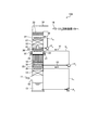
- FIG. 1 is a schematic diagram of a finish flue gas desulfurization apparatus according to a first embodiment.
- FIG. 2 is a schematic diagram of a finish flue gas desulfurization apparatus according to a second embodiment.
- FIG. 3 is a schematic diagram of a finish flue gas desulfurization apparatus according to a third embodiment.
- FIG. 4 is a schematic diagram of another finish flue gas desulfurization apparatus according to the third embodiment.
- FIG. 5 is a schematic diagram of an exhaust gas treatment system according to a fourth embodiment.
- FIG. 6 is a diagram illustrating an example of an exhaust gas treatment system.
- FIG. 1 is a schematic diagram of a finish flue gas desulfurization apparatus according to a first embodiment.
- the final flue gas desulfurization apparatus 10A according to the first embodiment removes sulfur oxide from combustion exhaust gas in advance with an existing desulfurization apparatus (not shown), and then reduces the remaining sulfur oxide to an extremely low level.
- a finishing desulfurization apparatus main body (hereinafter referred to as “apparatus main body”) 15 provided with a finishing desulfurization section 14 for desulfurization by bringing the liquid 13 into contact therewith, and a downstream side of the finishing desulfurization section 14 in the finishing desulfurization apparatus main body 15;
- a wet electrostatic precipitator 16 that removes soot and dust in the exhaust gas after the final desulfurization, a cooling unit 17 that cools the exhaust gas, provided in either one of the front and rear of the wet electrostatic precipitator 16, and dust removal and cooling After
- the gas discharge portion 19 for discharging to the outside the combustion exhaust gas (purified gas) 18 is intended to provided.
- the finishing desulfurization section 14 is supplied with lime (CaCO 3 ) absorbing liquid through the circulation line L 1 by the pump P 1 as the absorbing liquid 13 for removing sulfur oxide of the lime gypsum method.
- the wet electrostatic precipitator 16 is supplied with cleaning water 31 for the electrodes through a circulation line L 2 by a pump P 2 .
- the cooling unit 17 is supplied with cooling water 32 through a circulation line L 3 by a pump P 3 .
- Reference numeral 21 denotes an insulator support, 22 an insulator, 23 a mist eliminator, 33 a Jinkasa chimney tray, 34 a distributed chimney tray, and 35 to 37 nozzles.
- the exhaust gas 11 from which sulfur oxide has been removed in advance can be further desulfurized by the finish desulfurization unit 14, and most of the remaining sulfur oxide is removed. can do. Thereafter, the soot can be removed by the wet electrostatic precipitator 16 provided on the upper side of the finish desulfurizer 14.
- the absorbent 13 used in the finish desulfurization unit 14 NaOH, Na 2 CO 3 , NaHCO 3 , Ca (OH) 2 , Mg (OH) 2 and the like can be exemplified in addition to CaCO 3 .
- the cleaning water 31 used in the wet electrostatic precipitator 16 include Na 2 CO 3 and NaHCO 3 in addition to NaOH.
- tanks for supplying the absorbing liquid 13 and the cleaning water 31 are omitted in the drawing.
- the finish desulfurization part 14 and the wet electric dust collection part 16 are made into a similar cross-sectional area (substantially the same cross-sectional structure or a similar cross-sectional structure). This is because, if the structure is greatly widened or expanded, a portion where the gas flow rate is uneven is formed, and the contact efficiency between the exhaust gas and the electrode of the wet dust remover may be lowered, and the dust removal performance may be lowered.
- the preferred gas flow rate of the finish flue gas desulfurization equipment is 2.0 to 3.8 m / s
- the preferred gas flow rate of the wet dust collector is 2.0 to 3.0 m / s.
- a flow rectifying plate is provided at a place where drift in the tower is presumed to occur in advance to suppress gas drift, or a partition-like shape is provided in the finish flue gas desulfurization apparatus having a relatively fast gas flow velocity range.
- a suitable gas flow rate zone may be optimally controlled by providing a jammer plate.
- a suitable gas flow velocity zone for example, 2.5 m / s
- good desulfurization treatment and dust removal treatment may be performed.
- a highly purified purified gas 18 having a sulfur oxide concentration of 10 ppm or less (SO 2 ⁇ 1 to 3 ppm, SO 3 ⁇ 1 to 3 ppm) and a soot concentration of 10 mg / m 3 N or less. can be obtained.
- the cooling unit 17 that cools the exhaust gas is provided on the downstream side of the wet electrostatic precipitator 16, but the present invention is not limited to this, and the upstream side of the wet electrostatic precipitator 16. You may make it provide in (between the finishing desulfurization part 14 and the wet electric dust collection part 16).
- the chimney tray for recovering the cooling water 32 provided at the lower part of the cooling unit 17 either a Jinkasa type chimney tray or a distributed type chimney tray may be used as long as a desired cooling effect can be obtained.
- the chimney tray that collects the washing water 31 in the lower part of the wet electrostatic precipitator 16 is preferably a distributed chimney tray in order to suppress the drift of the exhaust gas.
- the wet electrostatic precipitator 16 is provided on the upper side of the finish desulfurizer 14 so that the removal of soot and dust can be processed at the same time.
- a well-known watering type, jet type, filling type, liquid column type desulfurization apparatus can be used in the finishing desulfurization part 14.
- the exhaust gas 11 is rectified, the rectified gas is supplied to the wet electric dust collection section 16, the contact efficiency with the electrode surface is improved, and the dust collection ability by rectification Will improve.
- the site area can be reduced by integrating the finish desulfurization section and the wet electric dust collection section.
- a connecting duct is required. At this time, when exhaust gas flows in through the connecting duct, it is necessary to connect with a bent duct or the like. Yes, as a result, drift occurs, and the dust removal performance in the wet dust collector decreases.
- this can be solved by using an integrated type.
- the liquid desulfurization apparatus when used in the final desulfurization section 14, for example, 200A to 350A spray pipes are arranged at a pitch of about 0.5 m.
- this functions as a gas rectifying resistance structure, and the liquid falling to the pipe also contributes to resistance pressure loss. It will be.
- the gas rectifying resistance effect in the finish desulfurization section 14 due to the gas rectifying resistance effect in the finish desulfurization section 14, the drift of the gas introduced into the wet electrostatic precipitator 16 integrated in the upper part is suppressed. As a result, the dust collection performance in the wet electric dust collection unit 16 can be improved.
- the decarburization equipment is expected to be applied to existing thermal power in addition to new thermal power due to increasing demand for CO 2 reduction.
- the wet electrostatic precipitator 16 and the finish desulfurizer 14 that have been separately provided in the same cross section, it is possible to install a decarburization / dust removal facility, which facilitates application.
- the wet electric dust collector is provided in one stage inside the apparatus main body 15.
- the present invention is not limited to this, and two stages may be provided continuously. Good.
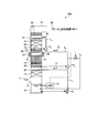
- FIG. 2 is a schematic diagram of a finish flue gas desulfurization apparatus according to a second embodiment.
- the finishing flue gas desulfurization apparatus 10B according to the second embodiment is configured to extract the cleaning water 31 used in the wet electric dust collection unit 16 through the line L 4 in the finishing flue gas desulfurization apparatus 10A according to the first embodiment.
- the cleaning water 31 is supplied into the absorbing liquid (CaCO 3 ) 13 stored on the lower side of the apparatus body 15 as necessary.
- the washing water 31 for example, by using a strong alkali agent such as NaOH, the desulfurization performance can be further improved.
- the cleaning liquid 31 may be supplied while being monitored by the pH meter 41.
- the combustion exhaust gas (exhaust gas) 11 having a sulfur oxide concentration higher than the allowable value is introduced in the gas introduction unit 12, it becomes particularly effective, and the purified combustion exhaust gas (purified gas) in the gas discharge unit 19 is obtained.
- the concentration of sulfur oxide in 18 can be made extremely low.
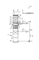
- FIG. 3 is a schematic diagram of a finish flue gas desulfurization apparatus according to a third embodiment.
- the final flue gas desulfurization apparatus 10 ⁇ / b> C according to the third embodiment is the same as that of the final flue gas desulfurization apparatus 10 ⁇ / b> A according to the first embodiment. It is used as the absorbing liquid of the unit 14 and is shared as the absorbing / cleaning liquid 42. As shown in FIG.
- the dispersive chimney tray 34 that collects the cleaning water 31 provided in the lower stage of the wet electrostatic precipitator 16 is removed, and the cleaning liquid is dropped as it is.
- the first and second orifices 43A and 43B are interposed in the lines L 11 and L 12 in order to set the supply amount of the strong alkaline liquid absorption / cleaning liquid 42 to a desired flow rate.
- the cleaning water that contributes to the cleaning of the electrode in the wet electrostatic precipitator 16 can be used as it is as the absorbent of the finishing desulfurization unit 14.
- both the absorbing liquid in the finishing desulfurization unit 14 and the cleaning liquid in the wet electrostatic precipitator 16 are the same kind of strong alkali and the same concentration, both the cleaning water and the absorbing liquid can be shared and stored. Auxiliary facilities such as tanks and pumps can be shared.
- a purified gas cooling apparatus 45 for cooling purified gas 18 after precision desulfurization and precision dust removal, and a CO 2 recovery apparatus are further provided.
- a portion of the gas introduced into the CO 2 recovering apparatus 106, via a line L 20, is supplied by the fan 46 as the seal gas 47 of the insulator 22 of the wet electrostatic precipitator unit 16 ( ⁇ 1).
- the seal gas 47 is supplied to the insulator chamber in which the insulator 22 is accommodated, and is constantly ventilated inside the wet electrostatic precipitator 16 to prevent the ingress of exhaust gas. This eliminates the need for separately installed seal air fan equipment costs and electricity costs.
- the gas processing amount is about It can be reduced by about 5%.
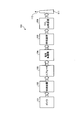
- FIG. 5 shows a schematic configuration diagram of an exhaust gas treatment system according to an embodiment of the present invention.
- the exhaust gas treatment system 50 according to the fourth embodiment recovers the heat in the gas after removing the NOx removal device 102 that removes nitrogen oxide in the exhaust gas G from the boiler 101, for example.
- the purified gas 18 supplied to the CO 2 recovery device 106 installed on the rear stage side of the final flue gas desulfurization device 10A has a very low concentration of sulfur oxide, and is circulated and used in the CO 2 recovery device 106. Accumulation of sulfur oxides and soot and dust in the CO 2 absorbing liquid (for example, amine absorbing liquid) is reduced, and deterioration can be suppressed. As a result, reduction of CO 2 absorption performance of the CO 2 absorbing liquid due to the deterioration is reduced, it is possible to perform stable recovery of CO 2.
- the CO 2 absorbing liquid for example, amine absorbing liquid
Landscapes
- Engineering & Computer Science (AREA)
- Chemical & Material Sciences (AREA)
- Environmental & Geological Engineering (AREA)
- Health & Medical Sciences (AREA)
- Biomedical Technology (AREA)
- Analytical Chemistry (AREA)
- General Chemical & Material Sciences (AREA)
- Oil, Petroleum & Natural Gas (AREA)
- Chemical Kinetics & Catalysis (AREA)
- Treating Waste Gases (AREA)
- Electrostatic Separation (AREA)
- Compounds Of Alkaline-Earth Elements, Aluminum Or Rare-Earth Metals (AREA)
Applications Claiming Priority (2)
| Application Number | Priority Date | Filing Date | Title |
|---|---|---|---|
| JP2010045905A JP5705443B2 (ja) | 2010-03-02 | 2010-03-02 | 仕上げ排煙脱硫装置及びこれを用いた排ガス処理システム |
| JP2010-045905 | 2010-03-02 |
Publications (1)
| Publication Number | Publication Date |
|---|---|
| WO2011108324A1 true WO2011108324A1 (ja) | 2011-09-09 |
Family
ID=44541992
Family Applications (1)
| Application Number | Title | Priority Date | Filing Date |
|---|---|---|---|
| PCT/JP2011/051947 Ceased WO2011108324A1 (ja) | 2010-03-02 | 2011-01-31 | 仕上げ排煙脱硫装置及びこれを用いた排ガス処理システム |
Country Status (2)
| Country | Link |
|---|---|
| JP (1) | JP5705443B2 (https=) |
| WO (1) | WO2011108324A1 (https=) |
Cited By (5)
| Publication number | Priority date | Publication date | Assignee | Title |
|---|---|---|---|---|
| CN102688682A (zh) * | 2012-05-16 | 2012-09-26 | 浙江菲达环保科技股份有限公司 | 一种烟气脱硫塔 |
| JP2015127046A (ja) * | 2013-12-30 | 2015-07-09 | シャンハイ クライド ベルゲマン マシナリー カンパニー リミテッド | 煙道ガス処理装置 |
| CN105903337A (zh) * | 2016-06-21 | 2016-08-31 | 南通亚泰工程技术有限公司 | 一种烟气脱硫提效、除尘、脱水一体化装置 |
| US9839916B2 (en) | 2012-07-20 | 2017-12-12 | Mitsubishi Hitachi Power Systems Environmental Solutions, Ltd. | Wet-type electric dust collection device and dust removal method |
| WO2023199662A1 (ja) | 2022-04-15 | 2023-10-19 | 三菱重工業株式会社 | 集塵システム及び集塵方法 |
Families Citing this family (8)
| Publication number | Priority date | Publication date | Assignee | Title |
|---|---|---|---|---|
| US9492786B2 (en) | 2011-11-22 | 2016-11-15 | Fluor Corporation | Multi-purpose absorber |
| US8545782B1 (en) * | 2012-10-16 | 2013-10-01 | Mitsubishi Heavy Industries, Ltd. | CO2 recovery apparatus and CO2 recovery method |
| CN104014229A (zh) * | 2014-06-20 | 2014-09-03 | 北京中冶隆生环保科技发展有限公司 | 烟气多级涡轮增压湍流湿法同时脱硫脱硝装置及使用方法 |
| CN104028096A (zh) * | 2014-06-20 | 2014-09-10 | 北京中冶隆生环保科技发展有限公司 | 烟气增压湍流湿法脱硝及脱硝废液回用技术 |
| CN104324602B (zh) * | 2014-10-29 | 2016-05-25 | 鞍山红拖机械制造股份有限公司 | 一种烟尘废气污染源控制装置及工艺方法 |
| CN105214847A (zh) * | 2015-10-13 | 2016-01-06 | 佛山市博顿空气科技有限公司 | 餐饮油烟净化机电场自动清洗系统 |
| CN107684810A (zh) * | 2017-09-06 | 2018-02-13 | 河北环科力创环境工程有限公司 | 烟气超低排放装置及使用方法 |
| CN112547308B (zh) * | 2020-11-24 | 2023-04-18 | 临沂绿楠环保科技有限公司 | 一种工业湿式电除尘器 |
Citations (5)
| Publication number | Priority date | Publication date | Assignee | Title |
|---|---|---|---|---|
| JPS53111579A (en) * | 1977-03-10 | 1978-09-29 | Ebara Corp | Method of and for preventing creation of dew on insulators of electric dust collector |
| JPH07155537A (ja) * | 1993-12-08 | 1995-06-20 | Kansai Electric Power Co Inc:The | 高性能排ガス処理方法及び装置 |
| JPH11137954A (ja) * | 1997-11-10 | 1999-05-25 | Mitsubishi Heavy Ind Ltd | 重質油焚ボイラ排ガスの処理装置 |
| JP2001289430A (ja) * | 2000-04-06 | 2001-10-19 | Ishikawajima Harima Heavy Ind Co Ltd | 排ガス処理装置 |
| JP2009226367A (ja) * | 2008-03-25 | 2009-10-08 | Chiyoda Kako Kensetsu Kk | 脱硫脱炭装置および二酸化炭素除去方法 |
-
2010
- 2010-03-02 JP JP2010045905A patent/JP5705443B2/ja active Active
-
2011
- 2011-01-31 WO PCT/JP2011/051947 patent/WO2011108324A1/ja not_active Ceased
Patent Citations (5)
| Publication number | Priority date | Publication date | Assignee | Title |
|---|---|---|---|---|
| JPS53111579A (en) * | 1977-03-10 | 1978-09-29 | Ebara Corp | Method of and for preventing creation of dew on insulators of electric dust collector |
| JPH07155537A (ja) * | 1993-12-08 | 1995-06-20 | Kansai Electric Power Co Inc:The | 高性能排ガス処理方法及び装置 |
| JPH11137954A (ja) * | 1997-11-10 | 1999-05-25 | Mitsubishi Heavy Ind Ltd | 重質油焚ボイラ排ガスの処理装置 |
| JP2001289430A (ja) * | 2000-04-06 | 2001-10-19 | Ishikawajima Harima Heavy Ind Co Ltd | 排ガス処理装置 |
| JP2009226367A (ja) * | 2008-03-25 | 2009-10-08 | Chiyoda Kako Kensetsu Kk | 脱硫脱炭装置および二酸化炭素除去方法 |
Cited By (6)
| Publication number | Priority date | Publication date | Assignee | Title |
|---|---|---|---|---|
| CN102688682A (zh) * | 2012-05-16 | 2012-09-26 | 浙江菲达环保科技股份有限公司 | 一种烟气脱硫塔 |
| US9839916B2 (en) | 2012-07-20 | 2017-12-12 | Mitsubishi Hitachi Power Systems Environmental Solutions, Ltd. | Wet-type electric dust collection device and dust removal method |
| JP2015127046A (ja) * | 2013-12-30 | 2015-07-09 | シャンハイ クライド ベルゲマン マシナリー カンパニー リミテッド | 煙道ガス処理装置 |
| US9782782B2 (en) | 2013-12-30 | 2017-10-10 | Shanghai Clyde Bergemann Machinery Co., Ltd. | Flue gas treatment device |
| CN105903337A (zh) * | 2016-06-21 | 2016-08-31 | 南通亚泰工程技术有限公司 | 一种烟气脱硫提效、除尘、脱水一体化装置 |
| WO2023199662A1 (ja) | 2022-04-15 | 2023-10-19 | 三菱重工業株式会社 | 集塵システム及び集塵方法 |
Also Published As
| Publication number | Publication date |
|---|---|
| JP2011177674A (ja) | 2011-09-15 |
| JP5705443B2 (ja) | 2015-04-22 |
Similar Documents
| Publication | Publication Date | Title |
|---|---|---|
| JP5705443B2 (ja) | 仕上げ排煙脱硫装置及びこれを用いた排ガス処理システム | |
| JP6045653B2 (ja) | Co2吸収液の飛散抑制方法 | |
| CA2801291C (en) | Air pollution control system and method | |
| JP5416679B2 (ja) | 排ガス処理方法と装置 | |
| CA2801169C (en) | Air pollution control system and method | |
| JP2015211969A (ja) | 排ガス処理システム及び方法 | |
| EP2537574B1 (en) | Air pollution control system and air pollution control method | |
| US8668889B2 (en) | Air pollution control system and method | |
| JP2011177674A5 (https=) | ||
| JP2010115602A (ja) | 湿式二段脱硫方法と装置 | |
| JP2013039511A (ja) | 湿式排煙脱硫装置およびそれを備えた火力発電プラント | |
| WO2011152546A1 (ja) | 排ガス処理システム及び方法 | |
| JP5144967B2 (ja) | 排ガス処理システム | |
| JP5859244B2 (ja) | 排煙処理設備と排煙処理方法 | |
| KR20080090359A (ko) | 탈질율과 열효율이 향상되는 보일러 시스템 | |
| CN203303814U (zh) | 用于烟气处理的除雾除尘装置以及烟气除雾除尘系统 | |
| CN104785094A (zh) | 锅炉烟气一体化脱硫除尘装置 | |
| CN204853524U (zh) | 一种脱硫除尘设备 | |
| JP2014121685A (ja) | 排ガス処理装置 | |
| JP2008062205A (ja) | ガス浄化装置、排煙脱硫システム、排ガス処理方法 | |
| EP3499121A1 (en) | Boiler equipment and operation method therefor | |
| CN202315669U (zh) | 多污染物烟气全面净化一体化装置 | |
| JP2008080261A (ja) | 排ガス処理方法 | |
| WO2016175163A1 (ja) | ガスクーラの洗浄排水処理方法と装置 | |
| JPS62176517A (ja) | 高炉・炉頂圧乾式発電における腐食性ガス除去システム |
Legal Events
| Date | Code | Title | Description |
|---|---|---|---|
| 121 | Ep: the epo has been informed by wipo that ep was designated in this application |
Ref document number: 11750437 Country of ref document: EP Kind code of ref document: A1 |
|
| NENP | Non-entry into the national phase |
Ref country code: DE |
|
| 122 | Ep: pct application non-entry in european phase |
Ref document number: 11750437 Country of ref document: EP Kind code of ref document: A1 |