WO2011108266A1 - 燃料電池システムおよびその運転方法 - Google Patents
燃料電池システムおよびその運転方法 Download PDFInfo
- Publication number
- WO2011108266A1 WO2011108266A1 PCT/JP2011/001224 JP2011001224W WO2011108266A1 WO 2011108266 A1 WO2011108266 A1 WO 2011108266A1 JP 2011001224 W JP2011001224 W JP 2011001224W WO 2011108266 A1 WO2011108266 A1 WO 2011108266A1
- Authority
- WO
- WIPO (PCT)
- Prior art keywords
- water
- water tank
- amount
- fuel cell
- tank
- Prior art date
Links
Images


Classifications
-
- H—ELECTRICITY
- H01—ELECTRIC ELEMENTS
- H01M—PROCESSES OR MEANS, e.g. BATTERIES, FOR THE DIRECT CONVERSION OF CHEMICAL ENERGY INTO ELECTRICAL ENERGY
- H01M8/00—Fuel cells; Manufacture thereof
- H01M8/04—Auxiliary arrangements, e.g. for control of pressure or for circulation of fluids
- H01M8/04298—Processes for controlling fuel cells or fuel cell systems
- H01M8/04313—Processes for controlling fuel cells or fuel cell systems characterised by the detection or assessment of variables; characterised by the detection or assessment of failure or abnormal function
- H01M8/0438—Pressure; Ambient pressure; Flow
- H01M8/04417—Pressure; Ambient pressure; Flow of the coolant
-
- H—ELECTRICITY
- H01—ELECTRIC ELEMENTS
- H01M—PROCESSES OR MEANS, e.g. BATTERIES, FOR THE DIRECT CONVERSION OF CHEMICAL ENERGY INTO ELECTRICAL ENERGY
- H01M8/00—Fuel cells; Manufacture thereof
- H01M8/04—Auxiliary arrangements, e.g. for control of pressure or for circulation of fluids
- H01M8/04082—Arrangements for control of reactant parameters, e.g. pressure or concentration
- H01M8/04089—Arrangements for control of reactant parameters, e.g. pressure or concentration of gaseous reactants
- H01M8/04119—Arrangements for control of reactant parameters, e.g. pressure or concentration of gaseous reactants with simultaneous supply or evacuation of electrolyte; Humidifying or dehumidifying
- H01M8/04156—Arrangements for control of reactant parameters, e.g. pressure or concentration of gaseous reactants with simultaneous supply or evacuation of electrolyte; Humidifying or dehumidifying with product water removal
-
- H—ELECTRICITY
- H01—ELECTRIC ELEMENTS
- H01M—PROCESSES OR MEANS, e.g. BATTERIES, FOR THE DIRECT CONVERSION OF CHEMICAL ENERGY INTO ELECTRICAL ENERGY
- H01M8/00—Fuel cells; Manufacture thereof
- H01M8/04—Auxiliary arrangements, e.g. for control of pressure or for circulation of fluids
- H01M8/04298—Processes for controlling fuel cells or fuel cell systems
- H01M8/04313—Processes for controlling fuel cells or fuel cell systems characterised by the detection or assessment of variables; characterised by the detection or assessment of failure or abnormal function
- H01M8/0438—Pressure; Ambient pressure; Flow
- H01M8/0441—Pressure; Ambient pressure; Flow of cathode exhausts
-
- H—ELECTRICITY
- H01—ELECTRIC ELEMENTS
- H01M—PROCESSES OR MEANS, e.g. BATTERIES, FOR THE DIRECT CONVERSION OF CHEMICAL ENERGY INTO ELECTRICAL ENERGY
- H01M8/00—Fuel cells; Manufacture thereof
- H01M8/04—Auxiliary arrangements, e.g. for control of pressure or for circulation of fluids
- H01M8/04298—Processes for controlling fuel cells or fuel cell systems
- H01M8/04313—Processes for controlling fuel cells or fuel cell systems characterised by the detection or assessment of variables; characterised by the detection or assessment of failure or abnormal function
- H01M8/04664—Failure or abnormal function
- H01M8/04686—Failure or abnormal function of auxiliary devices, e.g. batteries, capacitors
-
- H—ELECTRICITY
- H01—ELECTRIC ELEMENTS
- H01M—PROCESSES OR MEANS, e.g. BATTERIES, FOR THE DIRECT CONVERSION OF CHEMICAL ENERGY INTO ELECTRICAL ENERGY
- H01M8/00—Fuel cells; Manufacture thereof
- H01M8/04—Auxiliary arrangements, e.g. for control of pressure or for circulation of fluids
- H01M8/04298—Processes for controlling fuel cells or fuel cell systems
- H01M8/04694—Processes for controlling fuel cells or fuel cell systems characterised by variables to be controlled
- H01M8/04746—Pressure; Flow
- H01M8/04761—Pressure; Flow of fuel cell exhausts
-
- H—ELECTRICITY
- H01—ELECTRIC ELEMENTS
- H01M—PROCESSES OR MEANS, e.g. BATTERIES, FOR THE DIRECT CONVERSION OF CHEMICAL ENERGY INTO ELECTRICAL ENERGY
- H01M8/00—Fuel cells; Manufacture thereof
- H01M8/04—Auxiliary arrangements, e.g. for control of pressure or for circulation of fluids
- H01M8/04298—Processes for controlling fuel cells or fuel cell systems
- H01M8/04694—Processes for controlling fuel cells or fuel cell systems characterised by variables to be controlled
- H01M8/04746—Pressure; Flow
- H01M8/04768—Pressure; Flow of the coolant
-
- H—ELECTRICITY
- H01—ELECTRIC ELEMENTS
- H01M—PROCESSES OR MEANS, e.g. BATTERIES, FOR THE DIRECT CONVERSION OF CHEMICAL ENERGY INTO ELECTRICAL ENERGY
- H01M8/00—Fuel cells; Manufacture thereof
- H01M8/04—Auxiliary arrangements, e.g. for control of pressure or for circulation of fluids
- H01M8/04298—Processes for controlling fuel cells or fuel cell systems
- H01M8/04694—Processes for controlling fuel cells or fuel cell systems characterised by variables to be controlled
- H01M8/04955—Shut-off or shut-down of fuel cells
-
- H—ELECTRICITY
- H01—ELECTRIC ELEMENTS
- H01M—PROCESSES OR MEANS, e.g. BATTERIES, FOR THE DIRECT CONVERSION OF CHEMICAL ENERGY INTO ELECTRICAL ENERGY
- H01M8/00—Fuel cells; Manufacture thereof
- H01M8/04—Auxiliary arrangements, e.g. for control of pressure or for circulation of fluids
- H01M8/04007—Auxiliary arrangements, e.g. for control of pressure or for circulation of fluids related to heat exchange
- H01M8/04029—Heat exchange using liquids
-
- Y—GENERAL TAGGING OF NEW TECHNOLOGICAL DEVELOPMENTS; GENERAL TAGGING OF CROSS-SECTIONAL TECHNOLOGIES SPANNING OVER SEVERAL SECTIONS OF THE IPC; TECHNICAL SUBJECTS COVERED BY FORMER USPC CROSS-REFERENCE ART COLLECTIONS [XRACs] AND DIGESTS
- Y02—TECHNOLOGIES OR APPLICATIONS FOR MITIGATION OR ADAPTATION AGAINST CLIMATE CHANGE
- Y02E—REDUCTION OF GREENHOUSE GAS [GHG] EMISSIONS, RELATED TO ENERGY GENERATION, TRANSMISSION OR DISTRIBUTION
- Y02E60/00—Enabling technologies; Technologies with a potential or indirect contribution to GHG emissions mitigation
- Y02E60/30—Hydrogen technology
- Y02E60/50—Fuel cells
Definitions
- the present invention relates to a fuel cell system and an operation method thereof. More specifically, the present invention relates to a fuel cell system including a water tank and a water amount sensor and an operation method thereof.
- the fuel cell power generator used in the stationary cogeneration system is expected as a distributed power generator and a heat supply source.
- Conventional fuel cell power generators produce fuel from raw materials with a hydrogen generator and generate power with a cell stack.
- the heat generated during power generation can be used for hot water supply.
- the water that is generated at the same time is used for reactions when fuel is produced. For this reason, in the fuel cell power generator, it is important to effectively use water generated during power generation and to realize high reliability.
- the fuel cell system disclosed in Patent Document 1 includes a fuel cell, a water tank that stores water for cooling the fuel cell, and a controller, and the controller uses a water supply pump that supplies water to the water tank. If the water level detected by the first water level sensor is higher than the first water level even if the cumulative water discharge after the supply of water exceeds the first threshold, the water supply pump starts supplying water If the water level detected by the first water level sensor is less than the second water level even if the accumulated water supply amount after that becomes equal to or greater than the second threshold, or the water supply pump stops supplying water When the accumulated water discharge amount from is less than the third threshold value and the water level detected by the first water level sensor is equal to or lower than the third water level, an abnormal signal is transmitted.
- the present invention solves the above-described conventional problems, and an object of the present invention is to provide a fuel cell system and a method for operating the fuel cell system that can more reliably grasp an abnormality with a simpler configuration.
- a fuel cell system includes a fuel cell unit that generates power using a fuel gas and an oxidant gas, and moisture in the gas discharged from the fuel cell unit is condensed.
- a first water tank for storing at least one of condensed water, cooling water for cooling the fuel cell unit, and hot water for recovering heat from the fuel cell unit; the condensed water;
- a second water tank for storing at least one of cooling water and hot water, a first water sensor for detecting the amount of water in the first water tank, and a second water amount sensor for detecting the amount of water in the second water tank;
- a first water movement mechanism for moving water in the first water tank to the second water tank, and a control unit for controlling the first water movement mechanism, wherein the control Controls the first water movement mechanism so that water moves from the first water tank to the second water tank, and then the first water control mechanism before the start of the control of the first water control mechanism.
- the operation method of the fuel cell system of the present invention recovers the condensed water in which the moisture in the gas discharged from the fuel cell unit is condensed, the cooling water for cooling the fuel cell, and the heat from the fuel cell.
- Detecting the amount of water in a first water tank that stores at least one of hot water for storing with a first water amount sensor and storing at least one of the condensed water, the cooling water, and the hot water.
- the fuel cell system and the operation method thereof according to the present invention have an effect that the abnormality can be grasped more reliably with a simpler configuration by adopting the above configuration.
- FIG. 1 is a block diagram illustrating an example of a schematic configuration of the fuel cell system according to the first embodiment.
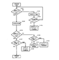
- FIG. 2 is a flowchart showing an example of the operation method of the fuel cell system according to the first embodiment.
- FIG. 2A shows a case where a determination operation is performed as an abnormal processing operation
- FIG. 2 (c) shows a case where the operation is stopped as an abnormality processing operation.
- FIG. 3 is a block diagram showing an example of a schematic configuration of the fuel cell system according to the first example of the first embodiment.
- FIG. 4 is a table showing an outline of determination in the fuel cell system in the first example of the first embodiment.
- FIG. 5 is a block diagram illustrating an example of a schematic configuration of the fuel cell system according to the second example of the first embodiment.
- FIG. 6 is a table showing an outline of determination in the fuel cell system in the second example of the first embodiment.
- FIG. 7 is a flowchart showing an example of an operation method of the fuel cell system in the first modification of the first embodiment.
- FIG. 8 is a block diagram illustrating an example of a schematic configuration of a fuel cell system according to a second modification of the first embodiment.
- FIG. 9 is a block diagram illustrating an example of a schematic configuration of a fuel cell system according to a third modification of the first embodiment.
- FIG. 10 is a block diagram illustrating an example of a schematic configuration of a fuel cell system according to a fourth modification of the first embodiment.
- FIG. 11 is a block diagram illustrating an example of a schematic configuration of a fuel cell system according to the second embodiment.
- FIG. 12 is a flowchart illustrating an example of an operation method of the initial operation process 1 in the second embodiment.
- FIG. 13 is a flowchart illustrating an example of the operation method of the initial operation step 2 in the second embodiment.
- FIG. 14 is a flowchart illustrating an example of an operation method of the initial operation process 3 in the second embodiment.
- FIG. 15 is a flowchart illustrating an example of the operation method of the initial operation step 4 in the second embodiment.
- FIG. 16 is a flowchart illustrating an example of the operation method of the cooling water / AD water draining step in the second embodiment.
- FIG. 17 is a flowchart showing an example of an operation method of a cooling water tank float sensor reforming water pump discrimination step in the second embodiment.
- FIG. 18 is a flowchart illustrating an example of an operation method of the AD tank float sensor AD closing valve determination step according to the second embodiment.
- FIG. 19 is a flowchart illustrating an example of an operation method of the periodic inspection step 1 in the second embodiment.
- FIG. 20 is a flowchart illustrating an example of an operation method of the periodic inspection step 2 in the second embodiment.
- FIG. 21 is a flowchart illustrating an example of an operation method of the periodic inspection step 3 in the second embodiment.
- a fuel cell system cools a fuel cell unit that generates power using fuel gas and oxidant gas, condensed water in which moisture in the gas discharged from the fuel cell unit is condensed, and the fuel cell unit.
- a first water tank for storing at least one of cooling water for cooling and hot water for recovering heat from the fuel cell unit, and at least one of condensed water, cooling water and hot water for storage
- a second water tank ; a first water sensor that detects the amount of water in the first water tank; a second water sensor that detects the amount of water in the second water tank; and the water in the first water tank is moved to the second water tank.
- a fuel cell system comprising a first water movement mechanism and a control unit that controls the first water movement mechanism, wherein the control unit is configured to move the water from the first water tank to the second water tank.
- Control the water transfer mechanism After that, when the amount of water detected by the first water amount sensor has not decreased compared to before the start of the control of the first water control mechanism, and compared to before the start of the control of the first water control mechanism.
- an abnormality determination operation that is at least one of a determination operation for determining abnormality, transmission of an abnormality signal, and operation stop is performed.
- the fuel cell system according to the second aspect of the present invention is the fuel cell system according to the first aspect, wherein the controller detects the amount of water detected by the first water amount sensor. The operation is continued when it decreases and the amount of water detected by the second water amount sensor increases.
- the fuel cell system according to a third aspect is the fuel cell system according to the first or second aspect, wherein the abnormal processing operation is operation stop, and the controller prohibits or restarts after the operation is stopped. I do.
- the fuel cell system according to a fourth aspect is the fuel cell system according to the first or second aspect, wherein the abnormality processing operation is a determination operation, and the control unit detects the first water amount sensor during the determination operation.
- the abnormality processing operation is a determination operation
- the control unit detects the first water amount sensor during the determination operation.
- a fuel cell system is the fuel cell system according to any one of the first to fourth aspects, wherein the first water tank is disposed above the second water tank in the direction of gravity, and the first water movement mechanism Has a first connection path for connecting the first water tank and the second water tank, and a first valve provided on the first connection path.
- a fuel cell system is the fuel cell system according to any one of the first to fourth aspects, wherein the first water movement mechanism includes a second connection path connecting the first water tank and the second water tank; A first pump provided on the second connection path for moving water from the first water tank to the second water tank.
- a fuel cell system is the fuel cell system according to the fifth aspect, further comprising a second water movement mechanism that moves the water in the second water tank to the first water tank.
- a third connection path connecting the 1 water tank and the second water tank; and a second pump provided on the third connection path for moving water from the second water tank to the first water tank.
- the controller uses the second water movement mechanism to move water from the second water tank to the first water tank before moving the water from the first water tank to the second water tank using the first water movement mechanism. Control to move.
- a valve when a valve is used as the first water moving mechanism, as a preparatory operation before performing at least one of an abnormality determination determination operation, an abnormal signal transmission, and an operation stop when a valve is used.
- the water can be moved from the second water tank to the first water tank.
- a fuel cell system is the fuel cell system according to the sixth aspect, further comprising a second water movement mechanism for moving the water in the second water tank to the first water tank, wherein the second water tank is the first water tank.
- the second water movement mechanism is disposed above the water tank in the direction of gravity, and includes a fourth connection path connecting the first water tank and the second water tank, and a second valve provided on the fourth connection path. Before the controller moves water from the first water tank to the second water tank using the first water transfer mechanism. Control to move water to the water tank.
- a pump when used as the first water transfer mechanism, as a preparatory operation before performing at least one of the determination operation for determining an abnormality, the transmission of an abnormality signal, and the shutdown of the abnormality.
- the water can be moved from the second water tank to the first water tank.
- a fuel cell system is the fuel cell system according to any one of the first to eighth aspects, further comprising a water discharge mechanism that discharges water from the second water tank, and the control unit includes the first water transfer mechanism. Before the water is transferred from the first water tank to the second water tank using the water, the water discharge mechanism is used to control the discharge of the water in the second water tank.
- the water in the second water tank can be discharged as a preparatory operation before performing at least one of an abnormality determination operation, an abnormal signal transmission, and an operation stop.
- the water discharge mechanism can use a valve or a pump.
- a fuel cell system is the fuel cell system according to any one of the first to ninth aspects, wherein the fuel cell unit generates a fuel gas containing hydrogen using a raw material and water, and a fuel A fuel cell that generates power using a gas and an oxidant gas; and a combustor that heats a hydrogen generator by burning at least one of a raw material, a fuel gas, and an anode exhaust gas discharged from the fuel cell.
- the condensed water is water obtained by condensing moisture in at least one of the anode exhaust gas, the cathode exhaust gas discharged from the fuel cell, and the combustion exhaust gas discharged from the combustor.
- the fuel cell system according to an eleventh aspect of the present invention is the fuel cell system according to the first aspect, wherein the abnormality processing operation is the transmission of an abnormal signal, and when the abnormal signal is transmitted, the abnormality notification device that notifies the abnormality.
- the operating method of the fuel cell system of the twelfth aspect of the invention recovers condensed water in which moisture in the gas discharged from the fuel cell unit is condensed, cooling water for cooling the fuel cell, and heat from the fuel cell. Detecting the amount of water in a first water tank that stores at least one of hot water for storage with a first water sensor, and second water tank storing at least one of condensed water, cooling water, and hot water.
- the case abnormal determination operation, transmission of the abnormality signal, and comprises a step of performing at least one of the abnormality processing operation of the shutdown, the.
- the operating method of the fuel cell system of the thirteenth aspect of the invention is the operating method of the fuel cell system of the twelfth aspect of the invention, which is detected by the first water amount sensor.
- the operation method of the fuel cell system of the fourteenth invention is the operation method of the fuel cell system of the twelfth invention, wherein the abnormal processing operation is operation stop, and the step of operation stop is prohibited after the operation stop. Or it restarts.
- the operating method of the fuel cell system of the fifteenth aspect of the invention is the operating method of the fuel cell system of the twelfth aspect of the invention, wherein the abnormality processing operation is a determining operation, When the amount of water to be detected does not decrease and the amount of water detected by the second water amount sensor increases, the step of determining that the first water amount sensor is abnormal, the amount of water detected by the first water amount sensor decreases, and 2 When the amount of water detected by the water amount sensor does not increase, the step of determining that the second water amount sensor is abnormal, the amount of water detected by the first water amount sensor does not decrease, and the amount of water detected by the second water amount sensor Determining that there is an abnormality in the first water movement mechanism when the increase has not increased.
- the abnormality processing operation is a determining operation
- a fuel cell system operating method is the fuel cell system operating method according to any of the twelfth to fifteenth aspects of the invention, wherein water is transferred from the first water tank to the second water tank using the first water movement mechanism.
- the step of moving the water from the second water tank to the first water tank using the second water movement mechanism for moving the water in the second water tank to the first water tank is provided before the step of moving the water.
- a pump when used as the first water transfer mechanism, as a preparatory operation before performing at least one of the determination operation for determining an abnormality, the transmission of an abnormality signal, and the shutdown of the abnormality.
- the water can be moved from the second water tank to the first water tank.
- a fuel cell system operating method is the fuel cell system operating method according to any one of the twelfth to sixteenth aspects, wherein water is transferred from the first water tank to the second water tank using the first water movement mechanism.
- the step of discharging the water of the second water tank using the water discharge mechanism for discharging the water of the second water tank is provided before the step of moving the water.
- the water in the second water tank can be discharged as a preparatory operation before performing at least one of an abnormality determination operation, an abnormal signal transmission, and an operation stop.
- the water discharge mechanism can use a valve or a pump.
- the operating method of the fuel cell system of the eighteenth invention is the operating method of the fuel cell system of the fourteenth invention, wherein the abnormality processing operation is the transmission of an abnormal signal, and when the abnormal signal is transmitted, an abnormality is indicated.
- reports is provided.
- FIG. 1 is a block diagram showing an example of a schematic configuration of the fuel cell system according to the first embodiment.
- the fuel cell system 100 of the present embodiment includes a fuel cell unit 50, a first water tank 41, a second water tank 43, a first water amount sensor 42, and a second water amount sensor 44. And a first water movement mechanism 60 and a control unit 40.
- the fuel cell unit 50 includes a fuel cell (not shown) that generates power using fuel gas and oxidant gas.
- a fuel cell for example, a polymer electrolyte fuel cell (PEFC) or a solid polymer fuel cell (SOFC) can be used.
- PEFC polymer electrolyte fuel cell
- SOFC solid polymer fuel cell
- the fuel cell unit 50 includes a hydrogen generator (not shown) that generates a fuel gas containing hydrogen using a raw material and water, and a fuel cell (not shown) that generates power using the fuel gas and an oxidant gas. And a combustor (not shown) that heats the hydrogen generator by burning at least one of the raw material, the fuel gas, and the anode exhaust gas discharged from the fuel cell.
- the condensed water described later may be water obtained by condensing moisture in at least one of the anode exhaust gas, the cathode exhaust gas discharged from the fuel cell, and the combustion exhaust gas discharged from the combustor. Good.
- the first water tank 41 collects condensed water in which moisture in the gas discharged from the fuel cell unit 50 is condensed, cooling water for cooling the fuel cell unit 50, and heat from the fuel cell unit 50. This tank stores at least one of the hot water stored in the tank.
- the second water tank 43 is a tank that accumulates at least one of condensed water, cooling water, and hot water storage.
- the 2nd water tank 43 is a tank which stores the fluid different from the fluid which the 1st water tank 41 stores among condensed water, cooling water, and hot water storage.
- the first water amount sensor 42 is a sensor that detects the amount of water in the first water tank 41.
- a float sensor, an electric conductivity meter, or the like can be used.
- the second water amount sensor 44 is a sensor that detects the amount of water in the second water tank 43.
- a float sensor, an electric conductivity meter, or the like can be used.
- the first water moving mechanism 60 moves the water in the first water tank 41 to the second water tank 43, and for example, a pump, a valve, or the like can be used.
- the control unit 40 is a control device that controls the first water movement mechanism 60.
- the control unit 40 can be configured by, for example, a microcontroller, an MPU, a PLC (Programmable Logic Controller), a logic circuit, or the like, or a storage device such as a RAM or a ROM may be added to these devices.
- the control unit 40 may be configured by a single controller that performs centralized control, or may be configured by a plurality of controllers that perform distributed control in cooperation with each other.
- the function of controlling the first water movement mechanism 60 and the function of executing an abnormality processing operation to be described later may be configured by a single controller as a whole, and correspond to individual functions.
- One controller may be provided one by one, or a single controller or a plurality of controllers may be provided for any combination of functions.
- the control unit 40 is communicably connected to the first water tank 41, the first water amount sensor 42, the second water tank 43, the second water amount sensor 44, and the first water moving mechanism 60.
- the control unit 40 controls the first water movement mechanism 60 so that the water moves from the first water tank 41 to the second water tank 43, and then the first water movement mechanism 60 compared to before the control of the first water movement mechanism 60 is started. At least when the amount of water detected by the first water amount sensor 42 does not decrease, and when the amount of water detected by the second amount-of-water sensor 44 does not increase compared to before the control of the first water movement mechanism 60 is started. In one case, an abnormality processing operation that is at least one of a determination operation for determining an abnormality, transmission of an abnormality signal, and operation stop is performed.
- the abnormality processing operation may be performed by any one of the determination operation, the transmission of the abnormality signal, and the operation stop, or may be performed simultaneously or sequentially by any two of the three operations. Alternatively, all three operations may be performed simultaneously or sequentially.
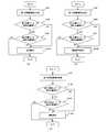
- FIG. 2 is a flowchart showing an example of the operation method of the fuel cell system according to the first embodiment.
- FIG. 2A shows a case where a determination operation is performed as an abnormal processing operation
- FIG. 2 (c) shows a case where the operation is stopped as an abnormality processing operation.
- the control unit 40 controls the first water movement mechanism 60 so that the water moves from the first water tank 41 to the second water tank 43 (step S101). .
- control unit 40 determines whether or not the detected water amount (for example, the water level) received from the first water amount sensor 42 is smaller than the detected water amount before step S101 (step S102). In order to enable such determination, the control unit 40 preferably detects and stores the amount of water in the first water tank 41 with the first water amount sensor 42 before step S101.
- the detected water amount for example, the water level
- step S ⁇ b> 102 If the determination result in step S ⁇ b> 102 is NO, the first water tank 41 has a malfunction due to a malfunction of the first water movement mechanism 60, despite the fact that water is being moved from the first water tank 41 to the second water tank 43. Although the amount of water has not decreased or the amount of water in the first water tank 41 has increased due to the movement of water from the first water tank 41 to the second water tank 43, The amount of water detected by the first water amount sensor 42 has not decreased. Therefore, it can be determined that at least one of the first water movement mechanism 60 and the first water amount sensor 42 is abnormal. Therefore, the control unit 40 executes a determination operation for determining that there is an abnormality (step S104A), and ends the operation (end). Specifically, for example, the determination operation may be to turn on an abnormality flag in a storage unit included in the control unit 40.
- step S102 determines whether or not the detected water amount (for example, the water level) received from the second water amount sensor 44 is greater than the detected water amount before step S101. (Step S103). In order to enable such determination, the control unit 40 preferably detects and stores the amount of water in the second water tank 43 with the second water amount sensor 44 before step S101.
- the detected water amount for example, the water level
- step S103 If the determination result in step S103 is YES, it is determined that there is no abnormality and the operation is ended (END). At this time, the amount of water detected by the first water amount sensor 42 has decreased, and the amount of water detected by the second water amount sensor 44 has increased, and the operation may be continued.
- step S104 determines whether the water has moved from the first water tank 41 to the second water tank 43 from the determination result in step S102. Therefore, the detected water amount of the second water amount sensor 44 is not increased. Therefore, it can be determined that the second water amount sensor 44 is abnormal. Therefore, the control unit 40 executes a determination operation for determining that there is an abnormality (step S104A), and ends the operation (end).
- the operation is ended, for example, when the operation of FIG. 2A is executed as an abnormality detection routine, the routine is ended, and the operation of the fuel cell system 100 is not necessarily stopped. Does not mean to be.
- step S102 and step S103 may be reversed (the same applies when an abnormal signal is transmitted or operation is stopped as an abnormal processing operation).
- the amount of water detected by the second water amount sensor 44 has increased, it is determined whether or not the amount of water detected by the first water amount sensor 42 has decreased.
- the determination operation step S104A is performed.
- the control unit 40 controls the first water movement mechanism 60 so that the water moves from the first water tank 41 to the second water tank 43, and then controls the first water movement mechanism 60.
- the amount of water detected by the first water amount sensor 42 does not decrease compared to before the start, and when the amount of water detected by the second water amount sensor 44 is smaller than before the control of the first water movement mechanism 60 is started.
- a determination operation for determining an abnormality is performed.
- step S104A in FIG. 2A is replaced with step S104B, and operations other than step S104B are the same as those in FIG. Therefore, description of steps common to FIG. 2A and FIG. 2B is omitted.
- step S104B the control unit 40 transmits an abnormality signal (step S104B) and ends the operation (end).
- the abnormal signal is not necessarily a signal that can be detected by the user.
- an abnormal signal may be transmitted to a monitoring facility in a remote place, or an abnormal signal may be transmitted to another device that performs an abnormal process.
- an abnormality may be notified. In this case, for example, when an abnormal signal is transmitted that is connected to the control unit 40 so as to be communicable, the abnormality is notified. An abnormality alarm may be provided.
- step S104A in FIG. 2A is replaced with step S104C, and operations other than step S104C are the same as those in FIG. Therefore, description of steps common to FIG. 2A and FIG. 2C is omitted.
- step S102 If the determination result of step S102 is NO, it can be determined that at least one of the first water movement mechanism 60 and the first water amount sensor 42 is abnormal, and the determination result of step S103 is NO, the second If it can be determined that there is an abnormality in the water amount sensor 44, the control unit 40 stops the operation of the fuel cell system 100 (step S104C) and ends the operation (END).
- the control unit 40 may perform start prohibition or restart after stopping the operation.
- the activation prohibition includes, for example, turning on the trajectory prohibition flag in the storage unit of the control unit 40, and thereafter preventing the activation even when the user presses the activation switch.
- FIG. 3 is a block diagram illustrating an example of a schematic configuration of a main part of the fuel cell system according to the first example of the first embodiment. Although omitted in FIG. 3, the fuel cell system of the first embodiment also includes a fuel cell unit 50 and a control unit 40. The elements described in FIG. 1 are denoted by the same reference numerals and names, and description thereof is omitted.
- the first water tank 41 is disposed above the first water amount sensor 42 in the gravity direction, and the first water moving mechanism 60 includes the first water tank 41 and the first water amount sensor. And a first valve 62 provided on the first connection path 61.
- the first connection path 61 is preferably provided so as to connect the drain port provided at the bottom of the first water tank 41 and the water supply port provided at the top of the second water tank 43.
- the first valve 62 may be, for example, an open / close valve or a flow rate adjustment valve that is communicably connected to the control unit 40 and is opened / closed by the control of the control unit 40.
- the first valve 62 when the first valve 62 is opened, the water in the first water tank 41 moves to the second water tank 43 by gravity.
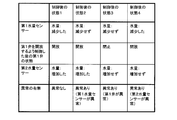
- FIG. 4 is a table showing an outline of determination in the fuel cell system in the first example of the first embodiment.
- the state of the first valve 62 is opened, and the water moves from the first water tank 41 to the second water tank 43. Then, the amount of water detected by the first water amount sensor 42 decreases as planned, and the amount of water detected by the second water amount sensor 44 increases as planned. Therefore, it can be determined that there is no abnormality from the detection results of the first water amount sensor 42 and the second water amount sensor 44.
- state 2 after the control by controlling to open the first valve 62, the state of the first valve 62 is opened, and water is moving from the first water tank 41 to the second water tank 43.
- the amount of water detected by the first water amount sensor 42 does not decrease as planned, and the amount of water detected by the second water amount sensor 44 increases as planned. In this case, it can be determined from the detection results of the first water amount sensor 42 and the second water amount sensor 44 that the first water amount sensor 42 is abnormal.
- the state of the first valve 62 remains closed, and the water has moved from the first water tank 41 to the second water tank 43. Absent. Then, the amount of water detected by the first water amount sensor 42 does not decrease as planned, and the amount of water detected by the second water amount sensor 44 does not increase as planned. In this case, it can be determined from the detection results of the first water amount sensor 42 and the second water amount sensor 44 that the first valve 62 is abnormal.
- state 4 after the control by controlling to open the first valve 62, the state of the first valve 62 is opened, and water is moving from the first water tank 41 to the second water tank 43.
- the amount of water detected by the first water amount sensor 42 has decreased as planned, but the amount of water detected by the second water amount sensor 44 has not increased as planned. In this case, it can be determined from the detection results of the first water amount sensor 42 and the second water amount sensor 44 that the second water amount sensor 44 is abnormal.
- an abnormal signal transmission or operation stop in addition to the determination operation, an abnormal signal transmission or operation stop, or any combination of these three may be executed simultaneously or sequentially.
- a valve when used as the first water movement mechanism, it is possible to perform at least one abnormality response operation of determination operation for determining abnormality, transmission of an abnormality signal, and operation stop.
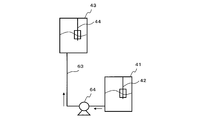
- FIG. 5 is a block diagram showing an example of a schematic configuration of a main part of the fuel cell system in the second example of the first embodiment. Although omitted in FIG. 5, the fuel cell system of the second embodiment also includes a fuel cell unit 50 and a control unit 40.
- the elements described in FIG. 1 are denoted by the same reference numerals and names, and description thereof is omitted.
- the first water movement mechanism 60 is provided on the second connection path 63 and the second connection path 63 that connect the first water tank 41 and the first water amount sensor 42, And a first pump 64 for moving water from the first water tank 41 to the second water tank 43.
- the second connection path 63 is provided so as to connect a drain port provided at the bottom of the first water tank 41 and a water supply port provided at the top of the second water tank 43.
- the first pump 64 may be, for example, a pump that is communicably connected to the control unit 40 and operates under the control of the control unit 40.
- the first pump 64 when the first pump 64 is driven, the water in the first water tank 41 moves to the second water tank 43. In such a configuration, even when the first water tank 41 is disposed below the second water tank 43 in the direction of gravity, the water is moved from the first water tank 41 to the second water tank 43 against the gravity. Can be made.
- FIG. 6 is a table showing an outline of determination in the fuel cell system in the second example of the first embodiment.
- the first pump 64 is actually operated by driving the first pump 64, and the water is moving from the first water tank 41 to the second water tank 43. Then, the amount of water detected by the first water amount sensor 42 decreases as planned, and the amount of water detected by the second water amount sensor 44 increases as planned. Therefore, it can be determined that there is no abnormality from the detection results of the first water amount sensor 42 and the second water amount sensor 44.
- the first pump 64 is actually operated by driving the first pump 64, and the water is moving from the first water tank 41 to the second water tank 43.
- the amount of water detected by the first water amount sensor 42 does not decrease as planned, and the amount of water detected by the second water amount sensor 44 increases as planned. In this case, it can be determined from the detection results of the first water amount sensor 42 and the second water amount sensor 44 that the first water amount sensor 42 is abnormal.
- the first pump 64 does not actually operate, and the water moves from the first water tank 41 to the second water tank 43. Absent. Then, the amount of water detected by the first water amount sensor 42 does not decrease as planned, and the amount of water detected by the second water amount sensor 44 does not increase as planned. In this case, it can be determined from the detection results of the first water amount sensor 42 and the second water amount sensor 44 that the first valve 62 is abnormal.
- the first pump 64 is actually operated by driving the first pump 64, and the water is moving from the first water tank 41 to the second water tank 43.
- the amount of water detected by the first water amount sensor 42 has decreased as planned, but the amount of water detected by the second water amount sensor 44 has not increased as planned. In this case, it can be determined from the detection results of the first water amount sensor 42 and the second water amount sensor 44 that the second water amount sensor 44 is abnormal.
- an abnormality signal transmission or operation stop in addition to the determination operation, an abnormality signal transmission or operation stop, or any combination of the three may be executed simultaneously or sequentially.
- FIG. 7 is a flowchart showing an example of an operation method of the fuel cell system in the first modification of the first embodiment.
- the abnormality processing operation is a determination operation, and the control unit 40 does not decrease the amount of water detected by the first water amount sensor 42 during the determination operation, and the second
- the control unit 40 does not decrease the amount of water detected by the first water amount sensor 42 during the determination operation, and the second
- the amount of water detected by the water amount sensor 44 increases, it is determined that the first water amount sensor 42 is abnormal, the amount of water detected by the first water amount sensor 42 decreases, and the amount of water detected by the second water amount sensor 44 increases. If not, it is determined that the second water amount sensor 44 is abnormal, the water amount detected by the first water amount sensor 42 has not decreased, and the water amount detected by the second water amount sensor 44 has not increased. It is determined that the first water movement mechanism 60 is abnormal.
- the abnormality processing operation is a determination operation
- the step of performing the determining operation is a step of determining that the first water amount sensor 42 is abnormal when the amount of water detected by the first water amount sensor 42 does not decrease and the amount of water detected by the second water amount sensor 44 increases.
- a step of determining that the first water movement mechanism 60 is abnormal when the amount of water detected by 42 does not decrease and the amount of water detected by the second water amount sensor 44 does not increase.
- the hardware configuration of the first modified example can be the same as that of the first embodiment and the examples and modified examples thereof, and detailed description thereof is omitted.
- the control unit 40 controls the first water movement mechanism 60 so that the water moves from the first water tank 41 to the second water tank 43 (step S201). .
- control unit 40 determines whether or not the detected water amount (for example, the water level) received from the first water amount sensor 42 is smaller than the detected water amount before step S201 (step S202). In order to enable such determination, it is preferable that the control unit 40 stores the detected water amount received from the first water amount sensor 42 before step S201.
- the detected water amount for example, the water level
- step S202 determines whether or not the detected water amount (for example, the water level) received from the second water amount sensor 44 is greater than the detected water amount before step S201. (Step S203).
- the detected water amount for example, the water level
- step S203 determines that there is no abnormality and ends the operation (end), for example, as shown in state 1 after control in FIG. 4 or FIG.
- step S203 determines that there is an abnormality in the second water amount sensor 44, for example, as shown in FIG. 4 or 6 as the state 4 after control (step S204). A flag to that effect is set and the operation ends (END).
- step S202 determines whether or not the detected water amount (for example, the water level) received from the second water amount sensor 44 is greater than the detected water amount before step S201. (Step S205).
- the detected water amount for example, the water level
- step S205 determines that there is an abnormality in the first water amount sensor 42, for example, as shown in FIG. 4 or FIG. 6 as the state 2 after control (step S206). A flag to that effect is set and the operation ends (END).
- step S206 determines that there is an abnormality in the first water moving mechanism 60, for example, as shown in FIG. 4 or 6 as the state 3 after control (step S206). A flag to that effect is set and the operation ends (END).
- the determination operation is performed.
- transmission of an abnormal signal and / or operation stop may be performed simultaneously or sequentially.
- FIG. 8 is a block diagram illustrating an example of a schematic configuration of a fuel cell system according to a second modification of the first embodiment.
- the fuel cell system of the second modification is the fuel cell system of the first embodiment, and includes a second water movement mechanism that moves the water in the second water tank 43 to the first water tank 41, and the second water movement mechanism is A third connection path 65 for connecting the first water tank 41 and the second water tank 43, and a third connection path 65 provided on the third connection path 65 for moving water from the second water tank 43 to the first water tank 41.
- the control unit 40 supplies water from the first water tank 41 to the second water tank 43 using the first water movement mechanism 60 (the first connection path 61 and the first valve 62). Before moving, control is performed to move water from the second water tank 43 to the first water tank 41 using the second water movement mechanism (the third connection path 65, the second pump 66).
- the operation method of the fuel cell system according to the second modification is the same as the operation method of the fuel cell system according to the first embodiment, in which water is transferred from the first water tank 41 to the second water tank 43 using the first water movement mechanism 60.
- the second water tank 43 is moved from the second water tank 43 using the second water movement mechanism (the third connection path 65, the second pump 66) that moves the water in the second water tank 43 to the first water tank 41.
- the step of moving water to the 1 water tank 41 is provided.
- the third connection path 65 is preferably provided so as to connect the drain port provided at the bottom of the second water tank 43 and the water supply port provided at the top of the first water tank 41.
- the second pump 66 may be, for example, a pump that is communicably connected to the control unit 40 and operates under the control of the control unit 40.
- the water in the second water tank 43 moves to the first water tank 41 by driving the second pump 66.
- the water is moved from the second water tank 43 to the first water tank 41 against the gravity. Can be made.
- a valve when used as the first water movement mechanism, a preparatory operation before performing at least one of an abnormality determination operation, an abnormal signal transmission, and an operation stop in response to an abnormality is determined.
- water can be moved from the second water tank to the first water tank.
- FIG. 9 is a block diagram illustrating an example of a schematic configuration of a fuel cell system according to a third modification of the first embodiment.
- the fuel cell system of the third modification is the fuel cell system of the second embodiment, and includes a second water movement mechanism that moves the water of the second water tank 43 to the first water tank 41.
- the second water tank 43 The second water movement mechanism is disposed above the first water tank 41 in the gravitational direction, and the second water movement mechanism is connected to the fourth connection path 67 connecting the first water tank 41 and the second water tank 43, and on the fourth connection path 67.
- the control unit 40 uses the first water movement mechanism 60 (the second connection path 63 and the first pump 64) to move from the first water tank 41 to the second water tank.
- the second water moving mechanism (the fourth connection path 67, the second valve 68) is used to control the water to move from the second water tank 43 to the first water tank 41.
- the operation method of the fuel cell system according to the third modification is the same as the operation method of the fuel cell system according to the second embodiment, in which water is transferred from the first water tank 41 to the second water tank 43 using the first water movement mechanism 60.
- the second water tank 43 is moved from the second water tank 43 using the second water movement mechanism (the fourth connection path 67, the second valve 68) that moves the water in the second water tank 43 to the first water tank 41.
- the step of moving water to the 1 water tank 41 is provided.
- connection path 67 is provided so as to connect a drain port provided at the bottom of the second water tank 43 and a water supply port provided at the top of the first water tank 41.
- the second valve 68 may be, for example, an on-off valve or a flow rate adjustment valve that is communicably connected to the control unit 40 and is opened and closed by the control of the control unit 40.
- the second valve 68 when the second valve 68 is opened, the water inside the second water tank 43 moves to the first water tank 41 due to gravity.
- a pump when used as the first water transfer mechanism, a preparatory operation before performing at least one of an abnormality determination operation, an abnormality signal transmission, and an operation stop in response to an abnormality is determined.
- water can be moved from the second water tank to the first water tank.
- FIG. 10 is a block diagram illustrating an example of a schematic configuration of a fuel cell system according to a fourth modification of the first embodiment.
- the fuel cell system 100A of the fourth modified example has a water discharge mechanism 69 for discharging water from the second water tank in the fuel cell system of the first embodiment, and the control unit 40 uses the water discharge mechanism to Before moving the water from the first water tank 41 to the second water tank 43, the water discharge mechanism 69 is used to control the discharge of the water in the second water tank 43.
- the operation method of the fuel cell system according to the fourth modification is the same as the operation method of the fuel cell system according to any of the above-described embodiments or modifications, in which water is transferred from the first water tank 41 to the second water tank 43 using the first water movement mechanism 60.
- the step of discharging the water of the second water tank 43 using the water discharge mechanism 69 for discharging the water of the second water tank 43 is provided before the step of moving the water.
- the fuel cell system 100A may include water storage means other than the first water tank 41 and the second water tank 43, and the water discharge mechanism 69 may discharge water to the water storage means. However, it is preferable that the water discharge mechanism 69 discharges the water in the second water tank 43 to the outside of the fuel cell system 100A.
- the water discharge mechanism 69 starts with, for example, a drain opening provided at the lower portion of the second water tank 43 and opens to the outside of the fuel cell system 100A, and a valve (open / close valve) provided in the flow path. , A flow regulating valve, etc.) or a pump.
- the water discharge mechanism 69 is connected to the control unit 40 so as to be communicable, for example, and discharges the water in the second water tank 43 to the outside of the second water tank 43 based on the control of the control unit 40.
- This modification may be combined with the first and second embodiments and the first to third modifications.
- the water in the second water tank is used as the second water tank. , More preferably outside the fuel cell system.
- FIG. 11 is a block diagram illustrating an example of a schematic configuration of a fuel cell system according to the second embodiment.
- the fuel cell power generation device 1 (fuel cell system) includes hydrogen from a cell stack 2 (fuel cell) that generates power using an oxidant gas containing fuel gas and at least oxygen, and raw material and water.
- a hydrogen generator 3 that generates fuel gas
- a condensed water tank 4 that accumulates water that has condensed through the air that has passed through the cell stack and the air discharged from the fuel generator, and the amount of water in the condensed water tank 4 is detected.
- a cooling water supply pump 10 as condensed water discharge means for discharging water from the condensed water tank 4
- the control unit 36 is provided.
- the cell stack 2 is supplied with air as an oxidant gas containing at least oxygen from the outside of the fuel cell power generator 1 through the cathode air pipe 14.
- the cathode air consumes part or all of the oxygen in the cathode air during power generation in the cell stack 2, and the remaining exhaust cathode air is guided to the exhaust cathode air heat exchanger 17 through the exhaust cathode air pipe 16. Since the exhaust cathode air contains a large amount of moisture, when the exhaust cathode air heat exchanger 17 removes heat and the temperature is lowered, the moisture is condensed and water is generated.
- the condensed water and the exhaust cathode air are guided to the condensed water tank 4 (cathode condensed water tank).
- the condensed water accumulates in the condensed water tank 4, and the gas component passes through the gas-liquid contact portion 21 provided in the condensed water tank 4 and is then discharged to the outside of the fuel cell power generator 1 through the cathode exhaust pipe 22.
- a substance having water in the molecule such as hydrocarbon is introduced from the outside of the fuel cell power generator 1 to the reforming section 3a of the hydrogen generator 3 through the raw material pipe 12 as a raw material.
- Raw materials include methane, ethane, In addition to propane and other gaseous hydrocarbons, kerosene and petroleum liquid hydrocarbons such as kerosene and petroleum can be used.
- city gas 13A is used as a raw material.
- a fuel gas containing hydrogen is generated by a reaction from the supplied raw material and water.
- the fuel produced by the hydrogen generator 3 is carried to the cell stack 2 by the fuel gas pipe 15.
- the cell stack 2 electric energy, thermal energy, and water are generated by hydrogen in the fuel and oxygen in the oxidant gas.
- the off gas after a part of hydrogen in the fuel gas is used in the cell stack 2 is guided to the AD heat exchanger 25 through the off gas pipe 23. Since the AD heat exchanger 25 takes heat from the off gas, the temperature of the off gas decreases, and the moisture contained in the off gas is condensed into water.
- the off gas containing condensed water is guided to the AD tank 6 (anode condensed water tank).
- Condensed water is stored in the AD tank 6, and off-gas is led to the burner unit 3 b in the hydrogen generator 3 through the AD pipe 24.
- the air taken into the fuel cell power generator 1 directly from the outside of the fuel cell power generator 1 or the air taken from the inside of the fuel cell power generator 1 and the off-gas are mixed by the combustion air pipe 13.
- Burn. Part of the heat generated during combustion is used as reaction heat for generating hydrogen from the raw material and water.
- Combustion exhaust gas containing heat not used as reaction heat is guided to the combustion exhaust gas heat exchanger 27 through the combustion exhaust gas pipe 26. In the combustion exhaust gas heat exchanger 27, heat is taken from the combustion exhaust gas, the temperature is lowered, and moisture is condensed.
- the combustion exhaust gas after the moisture is condensed is guided to the outside of the fuel cell power generator 1 by the combustion exhaust gas exhaust pipe 37.
- the water condensed from the combustion exhaust gas is guided to the gas-liquid contact portion 21 provided in the condensed water tank 4.
- Condensed water from the combustion exhaust gas has an acidic pH because carbon dioxide generated during combustion is contained in the combustion exhaust gas.
- the gas-liquid contact part 21 comes into contact with the exhaust cathode air in a facing manner.
- the carbon dioxide contained in the combustion exhaust gas moves to the exhaust cathode air having a low carbon dioxide concentration, so that the concentration of carbon dioxide in the condensed water from the combustion exhaust gas is lowered, the pH is raised, and it goes to neutrality. .
- the condensed water tank 4 is provided with a condensed water tank float sensor 5 as a condensed water amount sensor.
- a cooling water supply pump 10 is connected as a condensed water discharge means.
- the cooling water supply pump 10 carries water out of the condensed water tank 4 by a signal from the control unit 36.
- the water carried out from the condensed water tank 4 passes through a water purification unit that removes particles, ions, or bacilli contained in the water, and then is supplied to the cooling water tank 28 through a cooling water supply pipe 38.
- the cooling water supply means may be provided separately from the condensed water discharge means, in this embodiment, the cooling water supply pump 10 is used not only as the condensed water discharge means but also as the cooling water supply means.
- the cooling water tank 28 is provided with a cooling water tank float sensor 29 as a cooling water quantity sensor.
- the cooling water pumped out from the cooling water tank 28 by the cooling water circulation pump 30 is sent to the cooling water heat exchanger 31 from the cooling water tank 28. Since heat is taken away in the cooling water heat exchanger, the temperature of the cooling water becomes an appropriate temperature.
- the temperature of the cooling water is appropriately controlled by controlling the amount of hot water stored in the cooling water heat exchanger so that the heat moves so that the temperature becomes appropriate. Cooling water having an appropriate temperature is caused to flow into the cell stack 2. Since the cell stack 2 also generates heat during power generation, the temperature of the cell stack is appropriately controlled by flowing cooling water having an appropriate water temperature with an appropriate amount of water.
- a path for guiding water to the reforming water pump 32 is formed from a path through which the cooling water circulates between the cooling water tank 28 and the cell stack 2.
- the reforming water pump 32 guides the cooling water to the hydrogen generator 3 through the reforming water valve 33.
- the path connected to the AD tank 6 via the AD valve 34 is also configured in the discharge path of the reformed water pump 32.
- the cooling water discharge means and the AD tank water supply means may be provided independently, but in the present embodiment, the reforming water pump 32 is also used as the cooling water discharge means and the AD water supply means. Thereby, since a different role can be performed with a small number of parts, a highly reliable fuel cell power generator can be realized.
- the AD tank 6 is disposed above the condensed water tank 4, and water in the AD tank 6 is guided to the condensed water tank 4 by an AD pipe 9 provided with an AD closing valve 8.
- the AD stop valve is not only a condensed water supply means but also an AD water discharge means.
- the AD tank 6 stores condensed water from off-gas, but the fuel gas made from the raw material contains carbon dioxide in addition to hydrogen, so the condensed water from off-gas is generated by carbon dioxide.
- the water has a low pH. While being guided from the AD tank 6 to the condensed water tank 4, it passes through the gas-liquid contact portion 21. At this time, carbon dioxide in the condensed water moves and is removed by contact with the exhaust cathode air, so that the concentration of carbon dioxide in the condensed water is reduced and the pH becomes near neutral and is stored in the condensed water tank 4. It is. When the amount of supplied water is larger than the amount of water discharged from the condensed water tank 4, it is discharged from the condensed water drain pipe 39 to the outside of the fuel cell power generator 1.
- the direct current power generated in the cell stack 2 is sent to the power circuit unit 35 and converted into alternating current or direct current having a desired voltage to be used. It is sent to the outside of the power generator 1 and used.
- water is supplied from the outside of the fuel cell power generator 1 from the pipe 18 containing hot water, passes through the AD heat exchanger 25, and then the exhaust cathode air heat exchanger. 17 or the combustion exhaust gas heat exchanger 27, and the temperature rises every time it passes through the cooling water heat exchanger 31, and becomes hot hot water and is led to the outside of the fuel cell power generator 1 by the hot water storage discharge pipe. Used for hot water supply.
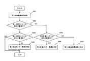
- FIG. 12 is a flowchart illustrating an example of an operation method of the initial operation process 1 in the second embodiment.
- the condensed water tank float sensor 5 should indicate a small amount of water (step S301).
- the control unit 36 can determine that the condensed water tank float sensor 5 has failed, and determines the failure (step S302).
- the water supply valve 20 is opened by the control part 36, and water is supplied to the condensed water tank 4 from the outside (step S303).
- the control unit 36 determines that both the water supply valve 20 and the condensed water tank float sensor 5 are normal. (Step S305), the process moves to the initial operation step 2.
- step S304 If the condensate tank float sensor 5 does not indicate a large amount of water even after the time (G2 / KYV) has elapsed (NO in step S304), either the water supply valve 20 or the condensate tank float sensor 5 is Judge that it is broken. In this case, the cooling water supply pump 10 is operated (step S306). Since the cooling water tank 28 does not contain water in the initial stage, the cooling water tank float sensor 29 indicates a small amount of water.
- step S307 When the cooling water supply pump 10 is operated and the cooling water tank float sensor 29 indicates a large amount of water (YES in step S307), the water supply valve 20 is normal because there is water in the condensed water tank 4, and the condensed water It can be determined that the tank float sensor 5 has failed (step S308). Even if the cooling water supply pump 10 is operated, if the cooling water tank float sensor 29 does not indicate a large amount of water (after a predetermined time has elapsed), it can be determined that the water supply valve 20 has failed (step S309). As a result, by stopping operation such as power generation or notifying a failure, it is possible to prompt a quick failure response without damaging other components, and a highly reliable fuel cell power generator can be realized. is there.
- FIG. 13 is a flowchart illustrating an example of the operation method of the initial operation step 2 in the second embodiment.
- the cooling water supply pump 10 is operated to put water into the cooling water tank 28 (step S401).
- the design water amount stored until the coolant tank float sensor 29 provided in the coolant tank 28 indicates a large amount of water is R2 liters
- the design flow rate of the water supplied from the coolant supply pump 10 is RKV liters per minute.
- the coolant tank float sensor 29 should indicate a large amount of water in (R2 / RKV) minutes.
- step S402 If the cooling water float sensor 29 indicates a large amount of water in (R2 / RKV) (YES in step S402), the cooling water tank can safely supply water if the cooling water tank float sensor 29 indicates a large amount of water. Since it can be determined that both the float sensor 29 and the cooling water supply pump 10 are normal (step S403), the process moves to the initial operation step 3. If the cooling water tank float sensor 29 does not indicate a large amount of water even if the time has passed (R2 / RKV) minutes (NO in step S402), either the cooling water tank float sensor 29 or the cooling water supply pump 10 is used. It is determined that one of them has failed.
- step S404 if the condensate tank float sensor 5 indicates that the amount of water is small (YES in step S404), it indicates that the water has been carried out from the condensate tank 4, and therefore it can be determined that the cooling water supply pump 10 is normal. Then, it is determined that the cooling water tank float sensor 29 is out of order (step S405). Conversely, if the condensed water tank float sensor 5 does not indicate a small amount of water (NO in step S404), it indicates that no water is being carried out from the condensed water tank 4, so that the cooling water supply pump 10 has failed. Confirm (step S406). By stopping the operation such as power generation or notifying a failure, it is possible to prompt a quick failure response without damaging other components, and to realize a highly reliable fuel cell power generator.
- FIG. 14 is a flowchart illustrating an example of an operation method of the initial operation process 3 in the second embodiment.
- step S503 When the AD tank float sensor 7 indicates a large amount of water for (AD2 / KPV) (YES in step S503), it can be determined that both the AD tank float sensor 7 and the reforming water pump 32 are normal (step S504). Therefore, it moves to the initial operation process 4. If the AD tank float sensor 7 does not indicate a large amount of water even after the time (AD2 / KPV) has elapsed (NO in step S503), the AD valve 34 is a valve at the discharge pressure of the reforming water pump 32.
- step S506 Since the spring pressure and direction of the valve are adjusted so that the valve opens, if the reforming water pump 32 is normal even if it fails, water will flow, so either the AD tank float sensor 7 or the reforming water pump 32 It is determined that one of them is out of order. In this case, if the cooling water tank float sensor 29 indicates a small amount of water (YES in step S505), it indicates that the water has been carried out from the cooling water tank 28. Therefore, it can be determined that the reforming water pump 32 is normal. It is determined that the AD tank float sensor 7 has failed (step S506).
- step S507 if the cooling water tank float sensor 29 does not indicate a small amount of water, it indicates that the water is not carried out from the cooling water tank 28, so that it is determined that the reforming water pump 32 has failed. .
- the cooling water tank float sensor 29 By stopping the operation such as power generation or notifying a failure, it is possible to prompt a quick failure response without damaging other components, and to realize a highly reliable fuel cell power generator.
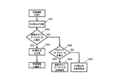
- FIG. 15 is a flowchart illustrating an example of the operation method of the initial operation step 4 in the second embodiment.
- the AD stop valve 8 is opened (step S601), and water is poured into the condensed water tank 4 from the AD pipe 9. If the design flow rate of the water supplied from the AD pipe 9 is AHV liters per minute before the condensed water tank float sensor 5 indicates a large amount of water, the condensed water tank float sensor 5 is within (AD2 / AHV) minutes. Should show a large amount of water.
- step S602 If the condensed water tank float sensor 5 indicates a large amount of water for (AD2 / AHV) (YES in step S602), it can be determined that the AD stop valve is normal (step S603), and the initial operation process is terminated. If the condensed water tank float sensor 5 does not show a large amount of water even after the time (AD2 / AHV) has elapsed (NO in step S602), either the condensed water tank float sensor 5 or the AD shutoff valve 8 is used. Is determined to be malfunctioning.
- step S604 if the AD tank float sensor 7 indicates that the amount of water is small (YES in step S604), it indicates that the water has been carried out from the AD tank 6, so it can be determined that the AD stop valve 8 is normal. It is determined that the tank float sensor 5 is out of order (step S605). Conversely, if the AD tank float sensor 7 does not indicate a small amount of water (NO in step S604), it indicates that no water has been carried out from the AD tank 6, so it is determined that the AD shutoff valve 8 has failed ( Step S606).
- the condensed water tank float sensor 5 since it is confirmed that there is no failure in the condensed water tank float sensor 5 in the initial operation step 1, the condensed water tank float sensor 5 does not indicate a large amount of water even if the time has elapsed after (AD2 / AHV) minutes. In this case, it may be immediately determined that the AD shutoff valve 8 has failed. Thus, by stopping the operation of power generation or notifying a failure, it is possible to prompt a quick failure response without damaging other components, and to realize a highly reliable fuel cell power generator. .
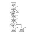
- FIG. 16 is a flowchart illustrating an example of the operation method of the cooling water / AD water draining step in the second embodiment.
- the AD valve 34 is opened (step S701), the reforming water pump 32 is operated (step S702), and the AD closing valve 8 is opened (step S703).
- the water in the cooling water tank 28 flows into the AD tank 6, and the water in the AD tank flows into the condensed water tank 4.
- the cooling water tank float sensor 29 should indicate a small amount of water.
- step S704 If the cooling water tank float sensor 29 indicates a small amount of water within a certain time (YES in step S704), the reforming water pump 32 is stopped (step S705), and the AD valve 34 is closed (step S706). If the cooling water tank float sensor 29 does not indicate a small amount of water within a certain time (NO in step S704 and YES in step S707), the control unit 36 sets the water drain failure flag 1 (step S708), and the reforming water pump 32 is stopped (step S705), and the AD valve 34 is closed (step S706). If the AD tank float sensor 7 indicates a small amount of water within a certain time (step S705), the AD stop valve 8 is closed.
- step S711 If the AD tank float sensor 7 does not indicate a small amount of water within a certain time (NO in step S709 and YES in step S710), the control unit 36 sets the water drain failure flag 2 (step S711), and sets the AD close valve 8 Close (step S712). If there is no failure flag ("None" in step S713), it is determined that the cooling water / AD water draining process has been completed normally, and the routine proceeds to the periodic inspection process 1. In the case of the drainage failure flag 1 (“1” in step S713), the process proceeds to the cooling water tank float sensor reforming water pump discrimination process. In the case of the drainage failure flag 2 (“2” in step S713), the AD tank float It moves to the sensor AD closing valve discrimination process.
- FIG. 17 is a flowchart showing an example of an operation method of a cooling water tank float sensor reforming water pump discrimination step in the second embodiment.
- the AD valve 34 is opened (step S801), and the reforming water pump 32 is operated (step S802).
- the AD tank float sensor 7 indicates a large amount of water within a certain time (YES in step S803), water is being sent out from the cooling water tank 28, so the cooling water tank float sensor 29 has failed. Is determined (step S804).
- step S803 If the AD tank float sensor 7 does not indicate a large amount of water within a certain time (NO in step S803), it is because water has not been sent, so it is determined that the reforming water pump 32 has failed (step S805). ). Thus, by stopping the operation of power generation or notifying a failure, it is possible to prompt a quick failure response without damaging other components, and to realize a highly reliable fuel cell power generator. .
- FIG. 18 is a flowchart illustrating an example of an operation method of the AD tank float sensor AD closing valve determination step according to the second embodiment.
- the cooling water supply pump 10 is operated until the condensed water tank float sensor 5 indicates a small amount of water (steps S901 to S902).
- the cooling water supply pump 10 is stopped (step S903).
- the AD valve 34 is opened (step S904).
- step S905 If the condensed water tank float sensor 5 indicates a large amount of water within a certain time (YES in step S905), water is being sent out from the AD tank 6, so that the AD tank It is determined that the float sensor 7 is out of order (step S906). If the condensate tank float sensor 5 does not indicate a large amount of water within a certain time (NO in step S905), it is because water has not been sent, so it is determined that the AD shutoff valve 8 has failed (step S907). ). Thus, by stopping the operation of power generation or notifying a failure, it is possible to prompt a quick failure response without damaging other components, and to realize a highly reliable fuel cell power generator. .
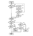
- FIG. 19 is a flowchart illustrating an example of an operation method of the periodic inspection step 1 in the second embodiment.
- the cooling water supply pump 10 is operated (step S1002).
- the water supply valve 20 is opened and closed (steps S1003 to S1004), and water is supplied to the condensed water tank 4. If the condensed water tank float sensor 5 indicates a large amount of water within a certain time, the cooling water supply pump 10 is operated to move to the step (step S1002).
- step S1005 If the condensate tank float sensor 5 does not indicate a large amount of water within a certain time (YES in step S1005), the controller 36 records the failure flag 3 (step S1006), and operates the cooling water supply pump 10 (step ( Move to step S1002). If the cooling water tank float sensor 29 indicates a large amount of water within a certain time (YES in step S1007), and there is no failure flag 3 ("NO" in step S1008), it is determined that there is no problem in the periodic inspection process 1, and Move to inspection process 2. If there is a failure flag 3 (“Yes” in step S1008), the condensed water tank float sensor 5 has failed, so it is determined that there is a failure (step S1009).
- step S1007 If the cooling water tank float sensor 29 does not indicate a large amount of water within a certain time (NO in step S1007) and there is no failure flag 3 ("NO" in step S1010), the failure flag 4 is set by the control unit 36. It records (step S1011) and moves to the periodic inspection process 2. If there is a failure flag 3 (“Yes” in step S1010), it is determined that the water supply valve 20 is in failure (step S1012). Thus, by stopping the operation of power generation or notifying a failure, it is possible to prompt a quick failure response without damaging other components, and to realize a highly reliable fuel cell power generator. .
- FIG. 20 is a flowchart illustrating an example of an operation method of the periodic inspection step 2 in the second embodiment.
- the AD valve 34 is opened (step S1101), and the reforming water pump 32 is operated (step S1102).
- the AD tank float sensor 7 indicates a large amount of water (YES in step S1103).
- the failure flag 4 is not present (“NO” in step S1104), it is determined that there is no problem in the periodic inspection process 2, and the periodic inspection process 3 Move to. If there is a failure flag 4 ("Yes" in step S1104), the cooling water tank float sensor 29 has failed, so it is determined that there is a failure (step S1105).
- Step S1107 If the AD tank float sensor 7 does not indicate a large amount of water within a certain time (NO in step S1103) and there is no failure flag 4 ("NO" in step S1106), the failure flag 5 is recorded by the control unit 36. (Step S1107), the process moves to the periodic inspection process 3. If there is the failure flag 4 (“Yes” in step S1106), it is determined that the reforming water pump 32 has failed (step S1108). Thus, by stopping the operation of power generation or notifying a failure, it is possible to prompt a quick failure response without damaging other components, and to realize a highly reliable fuel cell power generator. .
- FIG. 21 is a flowchart illustrating an example of an operation method of the periodic inspection step 3 in the second embodiment.
- the cooling water supply pump 10 is operated (step S1202) so that the condensed water tank float sensor 5 indicates a low water amount. If the condensed water tank float sensor 5 does not indicate a large amount of water even after a certain time (“Yes” in step S1203), it is determined that the condensed water tank float sensor 5 has failed (step S1204).
- step S1205 After the condensed water tank float sensor 5 indicates that the amount of water is low, the AD stop valve 8 is opened (step S1205), the condensed water tank float sensor 5 indicates that the amount of water is large (YES in step S1206), and there is no failure flag 5 (No in step S1207), it is determined that everything is normal, and the periodic inspection is terminated. If there is a failure flag 5 ("Yes" in step S1207), it is determined that the AD tank float sensor 7 has failed, so the AD tank float sensor 7 is determined to have failed (step S1208).
- step S1206 If the condensed water tank float sensor 5 does not indicate a large amount of water (NO in step S1206), if there is a failure flag 5 ("Yes" in step S1209), it is determined that the reforming water pump has failed (step S1210). If the failure flag 5 is not present, it is determined that the AD stop valve has failed (step S1211).
- the fuel cell system according to the present invention is useful because it can grasp an abnormality more reliably with a simpler configuration.
Abstract
燃料電池ユニット50と、凝縮水、冷却水、及び、貯湯水のうちの少なくとも1つを溜める第1水タンク41と、凝縮水、冷却水及び貯湯水のうちの少なくとも1つを溜める第2水タンク43と、第1水タンクの水量を検知する第1水量センサー42と、第2水タンクの水量を検知する第2水量センサー44と、第1水タンクの水を第2水タンクに移動させる第1水移動機構60と、第1水移動機構を制御する制御部40と、を備え、制御部が、第1水移動機構を制御し、その後、第1水制御機構の制御を開始する前と比べて第1水量センサーの検知する水量が減少しなかった場合、及び、第1水制御機構の上記制御を開始する前と比べて第2水量センサーの検知する水量が増加しなかった場合の少なくとも一方の場合に、異常と判定する判定動作、異常信号の発信、及び、運転停止のうちの少なくとも1つである異常処理動作を行う燃料電池システム。
Description
本発明は、燃料電池システムおよびその運転方法に関するものである。より詳細には,本発明は,水タンクと水量センサーとを備えた燃料電池システムおよびその運転方法に関するものである。
定置用コージェネレーションシステムに使用される燃料電池発電装置は、分散型の発電装置および熱供給源として期待されている。
従来の燃料電池発電装置は、水素生成器で原料から燃料を作り出し、セルスタックで発電を行う。発電時に発生する熱は給湯などに利用できる。同時に発生する水は、燃料を作り出す際の反応などで利用される。このため、燃料電池発電装置では、発電の際に発生する水を有効に利用し、かつ高い信頼性を実現することが重要となる。
特許文献1に開示された燃料電池システムは、燃料電池と、燃料電池を冷却する水を貯える水タンクと、制御器とを備え、制御器は、水タンクへ水を供給する水供給ポンプによる水の供給が停止してからの累積水排出量が、第1の閾値以上になっても第1水位センサで検知される水位が第1の水位より大きい場合、水供給ポンプによる水の供給を開始してからの累積水供給量が、第2の閾値以上になっても第1水位センサで検知される水位が第2の水位未満である場合、または水供給ポンプによる水の供給を停止してからの累積水排出量が、第3の閾値未満で、第1水位センサで検知される水位が第3の水位以下である場合、異常信号を発信する。
しかしながら、特許文献1に開示された構成では、累積水排出量又は累積水供給量を得るために、流量計を用いる、又は、算定器で計算をする必要がある。流量計を用いる場合は、排出経路又は供給経路に流量計を配置する必要があり、部品点数が増加し、コストが高くなるという課題があった。算定器で計算をする場合は、ポンプの操作量の指令値から推定される水流量及びポンプの動作時間のうちの少なくとも一方を用いて計算する場合と、弁の開放時間を用いて計算する場合とがある。しかし、ポンプ自体又は弁自体に異常がある場合には、累積水排出量又は累積水供給量を精確に計算ができず、異常を検知する精度が高められないという課題があった。
本発明は、上記従来の課題を解決するものであり、より簡便な構成で、より確実に異常を把握できる燃料電池システムおよびその運転方法を提供することを目的とする。
前記従来の課題を解決する為に、本発明の燃料電池システムは、燃料ガス及び酸化剤ガスを用いて発電を行なう燃料電池ユニットと、前記燃料電池ユニットから排出されるガス中の水分が凝縮した凝縮水、前記燃料電池ユニットを冷却するための冷却水、及び、前記燃料電池ユニットからの熱を回収するための貯湯水のうちの少なくとも1つを溜める第1水タンクと、前記凝縮水、前記冷却水及び前記貯湯水のうちの少なくとも1つを溜める第2水タンクと、前記第1水タンクの水量を検知する第1水量センサーと、前記第2水タンクの水量を検知する第2水量センサーと、前記第1水タンクの水を前記第2水タンクに移動させる第1水移動機構と、前記第1水移動機構を制御する制御部と、を備えた燃料電池システムであって、前記制御部は、前記第1水タンクから前記第2水タンクへ水が移動するよう前記第1水移動機構を制御し、その後、前記第1水制御機構の前記制御を開始する前と比べて前記第1水量センサーの検知する水量が減少しなかった場合、及び、前記第1水制御機構の前記制御を開始する前と比べて前記第2水量センサーの検知する水量が増加しなかった場合の少なくとも一方の場合に、異常と判定する判定動作、異常信号の発信、及び、運転停止のうちの少なくとも1つを行う。
また、本発明の燃料電池システムの運転方法は、燃料電池ユニットから排出されるガス中の水分が凝縮した凝縮水、燃料電池を冷却するための冷却水、及び、前記燃料電池からの熱を回収するための貯湯水のうちの少なくとも1つを溜める第1水タンクの水量を第1水量センサーで検知するステップと、前記凝縮水、前記冷却水及び前記貯湯水のうちの少なくとも1つを溜める第2水タンクの水量を第2水量センサーで検知するステップと、前記第1水タンクから前記第2水タンクへ水が移動するよう第1水移動機構を制御するステップと、その後、前記第1水移動機構を制御する前と比べて前記第1水量センサーの検知する水量が減少しなかった場合、及び、前記第1水移動機構を制御する前と比べて前記第2水量センサーの検知する水量が増加しなかった場合の少なくとも一方の場合に、異常と判定する判定動作、異常信号の発信、及び、運転停止のうちの少なくとも1つを行うステップと、を備えている。
本発明の燃料電池システムおよびその運転方法は、上記構成を採用することにより、より簡便な構成で、より確実に異常を把握できるという効果を奏する。
第1の発明の燃料電池システムは、燃料ガス及び酸化剤ガスを用いて発電を行なう燃料電池ユニットと、燃料電池ユニットから排出されるガス中の水分が凝縮した凝縮水、燃料電池ユニットを冷却するための冷却水、及び、燃料電池ユニットからの熱を回収するための貯湯水のうちの少なくとも1つを溜める第1水タンクと、凝縮水、冷却水及び貯湯水のうちの少なくとも1つを溜める第2水タンクと、第1水タンクの水量を検知する第1水量センサーと、第2水タンクの水量を検知する第2水量センサーと、第1水タンクの水を第2水タンクに移動させる第1水移動機構と、第1水移動機構を制御する制御部と、を備えた燃料電池システムであって、制御部は、第1水タンクから第2水タンクへ水が移動するよう第1水移動機構を制御し、その後、第1水制御機構の制御を開始する前と比べて第1水量センサーの検知する水量が減少しなかった場合、及び、第1水制御機構の上記制御を開始する前と比べて第2水量センサーの検知する水量が増加しなかった場合の少なくとも一方の場合に、異常と判定する判定動作、異常信号の発信、及び、運転停止のうちの少なくとも1つである異常処理動作を行う。
かかる構成では、より簡便な構成で、より確実に異常を把握できる
第2の発明の燃料電池システムは、第1の発明の燃料電池システムにおいて、制御部が、第1水量センサーの検知する水量が減少し、かつ、第2水量センサーの検知する水量が増加した場合に、運転を継続する。
第2の発明の燃料電池システムは、第1の発明の燃料電池システムにおいて、制御部が、第1水量センサーの検知する水量が減少し、かつ、第2水量センサーの検知する水量が増加した場合に、運転を継続する。
第3の発明の燃料電池システムは、第1または第2の発明の燃料電池システムにおいて、異常処理動作が、運転停止であって、制御部が、運転停止を行った後に、起動禁止又は再起動を行う。
第4の発明の燃料電池システムは、第1または第2の発明の燃料電池システムにおいて、異常処理動作が、判定動作であって、制御部が、判定動作の際に、第1水量センサーの検知する水量が減少せず、かつ、第2水量センサーの検知する水量が増加した場合に、第1水量センサーの異常と判定し、第1水量センサーの検知する水量が減少し、かつ、第2水量センサーの検知する水量が増加しなかった場合に、第2水量センサーの異常と判定し、第1水量センサーの検知する水量が減少せず、かつ、第2水量センサーの検知する水量が増加しなかった場合に、第1水移動機構の異常と判定する。
かかる構成では、第1水量センサー、第2水量センサ及び第1水移動機構のうちのどの機器が異常であるかを判定することができる。そのため、例えば、修理などのメンテナンスを行う際に、異常が起こった部品を作業者が容易に把握でき、部品交換をスムーズに行うことができる。
第5の発明の燃料電池システムは、第1~4のいずれかの発明の燃料電池システムにおいて、第1水タンクが、第2水タンクよりも重力方向の上側に配置され、第1水移動機構が、第1水タンク及び第2水タンクを接続する第1接続経路と、第1接続経路上に設けられた第1弁と、を有する。
かかる構成では、第1水移動機構として、弁を用いた場合に、異常と判定する判定動作、異常信号の発信、及び、運転停止のうちの少なくとも1つの異常時対応を行うことができる。
第6の発明の燃料電池システムは、第1~4のいずれかの発明の燃料電池システムにおいて、第1水移動機構が、第1水タンク及び第2水タンクを接続する第2接続経路と、第2接続経路上に設けられ、第1水タンクから第2水タンクに水を移動するための第1ポンプと、を有する。
かかる構成では、第1水移動機構として、ポンプを用いた場合に、異常と判定する判定動作、異常信号の発信、及び、運転停止のうちの少なくとも1つの異常時対応を行うことができる。
第7の発明の燃料電池システムは、第5の発明の燃料電池システムにおいて、第2水タンクの水を第1水タンクに移動する第2水移動機構を備え、第2水移動機構は、第1水タンク及び第2水タンクを接続する第3接続経路と、第3接続経路上に設けられ、第2水タンクから第1水タンクに水を移動するための第2ポンプと、を有し、制御部が、第1水移動機構を用いて第1水タンクから第2水タンクへ水を移動する前に、第2水移動機構を用いて、第2水タンクから第1水タンクに水を移動するよう制御する。
かかる構成では、第1水移動機構として、弁を用いた場合に、異常と判定する判定動作、異常信号の発信、及び、運転停止のうちの少なくとも1つの異常時対応を行う前の準備動作として、第2水タンクから第1水タンクに水を移動することができる。
第8の発明の燃料電池システムは、第6の発明の燃料電池システムにおいて、第2水タンクの水を第1水タンクに移動する第2水移動機構を備え、第2水タンクは、第1水タンクよりも重力方向の上側に配置され、第2水移動機構は、第1水タンク及び第2水タンクを接続する第4接続経路と、第4接続経路上に設けられた第2弁と、を有し、制御部が、第1水移動機構を用いて第1水タンクから第2水タンクへ水を移動する前に、第2水移動機構を用いて、第2水タンクから第1水タンクに水を移動するよう制御する。
かかる構成では、第1水移動機構として、ポンプを用いた場合に、異常と判定する判定動作、異常信号の発信、及び、運転停止のうちの少なくとも1つの異常時対応を行う前の準備動作として、第2水タンクから第1水タンクに水を移動することができる。
第9の発明の燃料電池システムは、第1~8のいずれかの発明の燃料電池システムにおいて、第2水タンクの水を排出する水排出機構を有し、制御部が、第1水移動機構を用いて第1水タンクから第2水タンクへ水を移動する前に、水排出機構を用いて第2水タンクの水を排出するよう制御する。
かかる構成では、異常と判定する判定動作、異常信号の発信、及び、運転停止のうちの少なくとも1つの異常時対応を行う前の準備動作として、第2水タンクの水を排出することができる。なお、水排出機構は、弁又はポンプを用いることができる。
第10の発明の燃料電池システムは、第1~9のいずれかの発明の燃料電池システムにおいて、燃料電池ユニットが、原料及び水を用いて水素を含む燃料ガスを生成する水素生成器と、燃料ガス及び酸化剤ガスを用いて発電を行なう燃料電池と、原料、燃料ガス及び燃料電池から排出されるアノード排ガスのうちの少なくともいずれかを燃焼して水素生成器を加熱する燃焼器と、を有し、凝縮水が、アノード排ガス、燃料電池から排出されるカソード排ガス、及び、燃焼器から排出される燃焼排ガスのうちの少なくともいずれかのガス中の水分を凝縮した水である。
第11の発明の燃料電池システムは、第1の発明の燃料電池システムにおいて、異常処理動作が、異常信号の発信であって、異常信号が発信された場合に異常の旨を報知する異常報知器を有する。
第12の発明の燃料電池システムの運転方法は、燃料電池ユニットから排出されるガス中の水分が凝縮した凝縮水、燃料電池を冷却するための冷却水、及び、燃料電池からの熱を回収するための貯湯水のうちの少なくとも1つを溜める第1水タンクの水量を第1水量センサーで検知するステップと、凝縮水、冷却水及び貯湯水のうちの少なくとも1つを溜める第2水タンクの水量を第2水量センサーで検知するステップと、第1水タンクから第2水タンクへ水が移動するよう第1水移動機構を制御するステップと、その後、第1水移動機構を制御する前と比べて第1水量センサーの検知する水量が減少しなかった場合、及び、第1水移動機構を制御する前と比べて第2水量センサーの検知する水量が増加しなかった場合の少なくとも一方の場合に、異常と判定する判定動作、異常信号の発信、及び、運転停止のうちの少なくとも1つである異常処理動作を行うステップと、を備える。
かかる構成では、より簡便な構成で、より確実に異常を把握できる
第13の発明の燃料電池システムの運転方法は、第12の発明の燃料電池システムの運転方法において、第1水量センサーの検知する水量が減少し、かつ、第2水量センサーの検知する水量が増加した場合に、運転を継続するステップを備える。
第13の発明の燃料電池システムの運転方法は、第12の発明の燃料電池システムの運転方法において、第1水量センサーの検知する水量が減少し、かつ、第2水量センサーの検知する水量が増加した場合に、運転を継続するステップを備える。
第14の発明の燃料電池システムの運転方法は、第12の発明の燃料電池システムの運転方法において、異常処理動作が、運転停止であって、運転停止を行うステップが、運転停止後に、起動禁止又は再起動を行うものである。
第15の発明の燃料電池システムの運転方法は、第12の発明の燃料電池システムの運転方法において、異常処理動作が、判定動作であって、判定動作を行うステップが、第1水量センサーの検知する水量が減少せず、かつ、第2水量センサーの検知する水量が増加した場合に、第1水量センサーの異常と判定するステップと、第1水量センサーの検知する水量が減少し、かつ、第2水量センサーの検知する水量が増加しなかった場合に、第2水量センサーの異常と判定するステップと、第1水量センサーの検知する水量が減少せず、かつ、第2水量センサーの検知する水量が増加しなかった場合に、第1水移動機構の異常と判定するステップと、を備える。
かかる構成では、第1水量センサー、第2水量センサ及び第1水移動機構のうちのどの機器が異常であるかを判定することができる。そのため、例えば、修理などのメンテナンスを行う際に、異常が起こった部品を作業者が容易に把握でき、部品交換をスムーズに行うことができる。
第16の発明の燃料電池システムの運転方法は、第12~15のいずれかの発明の燃料電池システムの運転方法において、第1水移動機構を用いて第1水タンクから第2水タンクへ水を移動するステップの前に、第2水タンクの水を第1水タンクに移動する第2水移動機構を用いて、第2水タンクから第1水タンクに水を移動するステップを備える。
かかる構成では、第1水移動機構として、ポンプを用いた場合に、異常と判定する判定動作、異常信号の発信、及び、運転停止のうちの少なくとも1つの異常時対応を行う前の準備動作として、第2水タンクから第1水タンクに水を移動することができる。
第17の発明の燃料電池システムの運転方法は、第12~16のいずれかの発明の燃料電池システムの運転方法において、第1水移動機構を用いて第1水タンクから第2水タンクへ水を移動するステップの前に、第2水タンクの水を排出する水排出機構を用いて第2水タンクの水を排出するステップを備える。
かかる構成では、異常と判定する判定動作、異常信号の発信、及び、運転停止のうちの少なくとも1つの異常時対応を行う前の準備動作として、第2水タンクの水を排出することができる。なお、水排出機構は、弁又はポンプを用いることができる。
第18の発明の燃料電池システムの運転方法は、第14の発明の燃料電池システムの運転方法において、異常処理動作が、異常信号の発信であって、異常信号が発信された場合に異常の旨を報知するステップを備える。
以下、本発明の実施の形態について、図面を参照しながら説明する。なお、この実施の形態によって本発明が限定されるものではない。符号は実施形態および実施例と発明との対応関係を例示するために付されており、発明の構成が実施形態およびその図面に限定されるものではない。
(第1実施形態)
図1は、図1は、第1実施形態における燃料電池システムの概略構成の一例を示すブロック図である。
図1は、図1は、第1実施形態における燃料電池システムの概略構成の一例を示すブロック図である。
図1に例示するように、本実施形態の燃料電池システム100は、燃料電池ユニット50と、第1水タンク41と、第2水タンク43と、第1水量センサー42と、第2水量センサー44と、第1水移動機構60と、制御部40とを備える。
燃料電池ユニット50は、燃料ガス及び酸化剤ガスを用いて発電を行なう燃料電池(図示せず)を備える。燃料電池としては、例えば、高分子電解質形燃料電池(PEFC)あるいは固体高分子形燃料電池(SOFC)などが用いられうる。
燃料電池ユニット50は、原料及び水を用いて水素を含む燃料ガスを生成する水素生成器(図示せず)と、燃料ガス及び酸化剤ガスを用いて発電を行なう燃料電池(図示せず)と、原料、燃料ガス及び燃料電池から排出されるアノード排ガスのうちの少なくともいずれかを燃焼して水素生成器を加熱する燃焼器(図示せず)と、を有していてもよい。この場合、後述する凝縮水は、アノード排ガス、燃料電池から排出されるカソード排ガス、及び、燃焼器から排出される燃焼排ガスのうちの少なくともいずれかのガス中の水分を凝縮した水であってもよい。
第1水タンク41は、燃料電池ユニット50から排出されるガス中の水分が凝縮した凝縮水、燃料電池ユニット50を冷却するための冷却水、及び、燃料電池ユニット50からの熱を回収するための貯湯水のうちの少なくとも1つを溜めるタンクである。
第2水タンク43も、第1水タンク41と同様、凝縮水、冷却水及び貯湯水のうちの少なくとも1つを溜めるタンクである。なお、第2水タンク43は、凝縮水、冷却水及び貯湯水のうち、第1水タンク41が溜める流体と異なる流体を溜めるタンクであることが好ましい。
第1水量センサー42は、第1水タンク41の水量を検知するセンサーであって、例えば、フロートセンサ、電気伝導度計などが用いられうる。
第2水量センサー44は、第2水タンク43の水量を検知するセンサーであって、例えば、フロートセンサ、電気伝導度計などが用いられうる。
第1水移動機構60は、第1水タンク41の水を第2水タンク43に移動させるもので、例えば、ポンプ、弁などが用いられうる。
制御部40は、第1水移動機構60を制御する制御装置である。制御部40は、例えば、マイクロコントローラ、MPU、PLC(ProgrammableLogic Controller)、論理回路等で構成することができ、あるいはこれらの装置に、RAMやROMなどの記憶装置が付加されてもよい。制御部40は、集中制御する単独の制御器によって構成されていてもよく、互いに協働して分散制御する複数の制御器によって構成されていてもよい。例えば、第1水移動機構60を制御する機能と、後述する異常処理動作を実行する機能とが、全体として1個の制御器によって構成されていてもよいし、個々の機能に対応するように1個ずつ制御器が設けられていてもよいし、各機能の任意の組合せについて単独のまたは複数の制御器が設けられていてもよい。
制御部40は、第1水タンク41と第1水量センサー42と第2水タンク43と第2水量センサー44と第1水移動機構60と、通信可能に接続されている。
制御部40は、第1水タンク41から第2水タンク43へ水が移動するよう第1水移動機構60を制御し、その後、第1水移動機構60の制御を開始する前と比べて第1水量センサー42の検知する水量が減少しなかった場合、及び、第1水移動機構60の上記制御を開始する前と比べて第2水量センサー44の検知する水量が増加しなかった場合の少なくとも一方の場合に、異常と判定する判定動作、異常信号の発信、及び、運転停止のうちの少なくとも1つである異常処理動作を行う。
異常処理動作は、上記判定動作、異常信号の発信、及び、運転停止のいずれか1つのみ行われてもよいし、3つの動作のうち任意の組合せの2つが同時または順次に行われてもよく、3つの動作全てが同時または順次に行われてもよい。
図2は、第1実施形態における燃料電池システムの運転方法の一例を示すフローチャートであって、図2(a)は異常処理動作として判定動作が行われる場合、図2(b)は異常処理動作として異常信号が発信される場合、図2(c)は異常処理動作として運転が停止される場合を示す。
まず、図2(a)を参照しつつ、異常処理動作として判定動作が行われる場合について説明する。動作が開示されると(スタート)、まず、制御部40により、第1水タンク41から第2水タンク43へ水が移動するように、第1水移動機構60が制御される(ステップS101)。
次に、制御部40は、第1水量センサー42から受け取った検知水量(例えば、水位)が、ステップS101より前の検知水量よりも減少しているか否かを判定する(ステップS102)。かかる判定を可能とするために、制御部40は、ステップS101よりも前に、第1水量センサー42で第1水タンク41の水量を検知して記憶しておくのが好ましい。
ステップS102の判定結果がNOであれば、第1水タンク41から第2水タンク43へ水を移動させようとしているにも関わらず、第1水移動機構60の不具合により第1水タンク41の水量が減少していないか、第1水タンク41から第2水タンク43へ水が移動して第1水タンク41の水量が増加しているにも関わらず、第1水量センサー42の不具合により第1水量センサー42の検知水量が減少していないことになる。よって、少なくとも第1水移動機構60および第1水量センサー42のいずれか一方に異常があると判断できる。そこで、制御部40は、異常と判定する判定動作を実行し(ステップS104A)、動作を終了する(エンド)。判定動作は、具体的には例えば、制御部40が有する記憶部にある、異常フラグをONとすることとしうる。
ステップS102の判定結果がYESであれば、制御部40は、第2水量センサー44から受け取った検知水量(例えば、水位)が、ステップS101より前の検知水量よりも増加しているか否かを判定する(ステップS103)。かかる判定を可能とするために、制御部40は、ステップS101よりも前に、第2水量センサー44で第2水タンク43の水量を検知して記憶しておくのが好ましい。
ステップS103の判定結果がYESであれば、異常なしと判定して動作を終了する(エンド)。このときは、第1水量センサー42の検知する水量が減少し、かつ、第2水量センサー44の検知する水量が増加しており、運転を継続してもよい。
ステップS104の判定結果がNOであれば、ステップS102の判定結果から第1水タンク41から第2水タンク43へと水が移動していることは確実であるから、第2水量センサー44の不具合により第2水量センサー44の検知水量が増加していないことになる。よって、第2水量センサー44に異常があると判断できる。そこで、制御部40は、異常と判定する判定動作を実行し(ステップS104A)、動作を終了する(エンド)。
なおここで、動作を終了する、とは、例えば、図2(a)の動作が異常検出ルーチンとして実行される場合に、該ルーチンが終了することをいい、必ずしも燃料電池システム100の運転が停止されることを意味しない。
なお、ステップS102とステップS103の順序は逆であってもよい(異常処理動作として異常信号の発信あるいは運転停止が行われる場合も同様である)。この場合、第2水量センサー44の検知水量が増加していた場合に、第1水量センサー42の検知水量が減少しているか否かの判定が行われる。第2水量センサー44の検知水量が増加していなかった場合、あるいは、第1水量センサー42の検知水量が減少していなかった場合には判定動作(ステップS104A)が行われる。
以上の動作によれば、制御部40により、第1水タンク41から第2水タンク43へ水が移動するよう第1水移動機構60を制御し、その後、第1水移動機構60の制御を開始する前と比べて第1水量センサー42の検知する水量が減少しなかった場合、及び、第1水移動機構60の上記制御を開始する前と比べて第2水量センサー44の検知する水量が増加しなかった場合の少なくとも一方の場合に、異常と判定する判定動作が実行されることになる。
次に、図2(b)を参照しつつ、異常処理動作として異常信号が発信される場合について説明する。なお、この場合の動作は、図2(a)のステップS104AをステップS104Bに置換したものであり、ステップS104B以外の動作は図2(a)と同様である。よって、図2(a)と図2(b)とで共通するステップについては説明を省略する。
ステップS102の判定結果がNOであり、少なくとも第1水移動機構60および第1水量センサー42のいずれか一方に異常があると判断できる場合、および、ステップS103の判定結果がNOであり、第2水量センサー44に異常があると判断できる場合には、制御部40は、異常信号を発信し(ステップS104B)、動作を終了する(エンド)。異常信号は、必ずしもユーザにより検知可能な信号でなくてもよい。例えば、遠隔地にある監視施設に異常信号が送信されてもよいし、異常処理を行う他の装置に異常信号が送信されてもよい。異常信号が発信された場合に異常の旨を報知してもよく、この場合には、例えば、制御部40と通信可能に接続された、異常信号が発信された場合に異常の旨を報知する異常報知器を備えていてもよい。
次に、図2(c)を参照しつつ、異常処理動作として運転が停止される場合について説明する。なお、この場合の動作は、図2(a)のステップS104AをステップS104Cに置換したものであり、ステップS104C以外の動作は図2(a)と同様である。よって、図2(a)と図2(c)とで共通するステップについては説明を省略する。
ステップS102の判定結果がNOであり、少なくとも第1水移動機構60および第1水量センサー42のいずれか一方に異常があると判断できる場合、および、ステップS103の判定結果がNOであり、第2水量センサー44に異常があると判断できる場合には、制御部40は、燃料電池システム100の運転を停止し(ステップS104C)、動作を終了する(エンド)。制御部40は、運転停止を行った後に、起動禁止又は再起動を行ってもよい。起動禁止とは、例えば、制御部40の記憶部にある軌道禁止フラグをONとし、その後はユーザが起動スイッチを押しても起動しないようにすることなどが挙げられる。
[第1実施例]
図3は、第1実施形態の第1実施例における燃料電池システムの主要部の概略構成の一例を示すブロック図である。図3においては省略されているが、第1実施例の燃料電池システムも、燃料電池ユニット50と制御部40とを備えている。図1において説明した要素については、同一の符号および名称を付して説明を省略する。
図3は、第1実施形態の第1実施例における燃料電池システムの主要部の概略構成の一例を示すブロック図である。図3においては省略されているが、第1実施例の燃料電池システムも、燃料電池ユニット50と制御部40とを備えている。図1において説明した要素については、同一の符号および名称を付して説明を省略する。
第1実施例の燃料電池システムでは、第1水タンク41が、第1水量センサー42よりも重力方向の上側に配置され、第1水移動機構60が、第1水タンク41及び第1水量センサー42を接続する第1接続経路61と、第1接続経路61上に設けられた第1弁62と、を有する。
第1接続経路61は、第1水タンク41の底部に設けられた排水口と、第2水タンク43の上部に設けられた給水口とを接続するように設けられているのが好ましい。
第1弁62は、例えば、制御部40と通信可能に接続され、制御部40の制御によって開閉される開閉弁あるいは流量調整弁としうる。第1実施例では、第1弁62が開放されることにより、第1水タンク41の内部にある水は、重力により、第2水タンク43へと移動する。
図4は、第1実施形態の第1実施例における燃料電池システムにおける判定の概要を示す表である。
制御後の状態1では、第1弁62を開放するよう制御することで、第1弁62の状態は開放となり、水は第1水タンク41から第2水タンク43へと移動している。そして、第1水量センサー42の検知水量は予定通り減少し、第2水量センサー44の検知水量は予定通り増加している。よって、第1水量センサー42と第2水量センサー44の検知結果から、異常なしと判定することができる。
制御後の状態2では、第1弁62を開放するよう制御することで、第1弁62の状態は開放となり、水は第1水タンク41から第2水タンク43へと移動している。しかしながら、第1水量センサー42の検知水量は予定通りには減少せず、第2水量センサー44の検知水量は予定通り増加している。この場合には、第1水量センサー42と第2水量センサー44の検知結果から、第1水量センサー42に異常があると判定することができる。
制御後の状態3では、第1弁62を開放するよう制御しても、第1弁62の状態は閉止のままで、水は第1水タンク41から第2水タンク43へと移動していない。そして、第1水量センサー42の検知水量は予定通りには減少せず、第2水量センサー44の検知水量も予定通りには増加しない。この場合には、第1水量センサー42と第2水量センサー44の検知結果から、第1弁62に異常があると判定することができる。
制御後の状態4では、第1弁62を開放するよう制御することで、第1弁62の状態は開放となり、水は第1水タンク41から第2水タンク43へと移動している。第1水量センサー42の検知水量は予定通り減少しているが、第2水量センサー44の検知水量は予定通りには増加していない。この場合には、第1水量センサー42と第2水量センサー44の検知結果から、第2水量センサー44に異常があると判定することができる。
なお、第1実施例においても、異常処理動作として、判定動作以外に、異常信号の発信あるいは運転停止、あるいはそれらの3つの任意の組合せが、同時にあるいは順次に実行されてもよい。
本実施例では、第1水移動機構として、弁を用いた場合に、異常と判定する判定動作、異常信号の発信、及び、運転停止のうちの少なくとも1つの異常時対応を行うことができる。
[第2実施例]
図5は、第1実施形態の第2実施例における燃料電池システムの主要部の概略構成の一例を示すブロック図である。図5においては省略されているが、第2実施例の燃料電池システムも、燃料電池ユニット50と制御部40とを備えている。図1において説明した要素については、同一の符号および名称を付して説明を省略する。
図5は、第1実施形態の第2実施例における燃料電池システムの主要部の概略構成の一例を示すブロック図である。図5においては省略されているが、第2実施例の燃料電池システムも、燃料電池ユニット50と制御部40とを備えている。図1において説明した要素については、同一の符号および名称を付して説明を省略する。
第2実施例の燃料電池システムでは、第1水移動機構60が、第1水タンク41及び第1水量センサー42を接続する第2接続経路63と、第2接続経路63上に設けられ、第1水タンク41から第2水タンク43に水を移動するための第1ポンプ64と、を有する。
第2接続経路63は、第1水タンク41の底部に設けられた排水口と、第2水タンク43の上部に設けられた給水口とを接続するように設けられているのが好ましい。
第1ポンプ64は、例えば、制御部40と通信可能に接続され、制御部40の制御によって動作するポンプとしうる。第2実施例では、第1ポンプ64が駆動されることにより、第1水タンク41の内部にある水は、第2水タンク43へと移動する。かかる構成では、第1水タンク41が第2水タンク43よりも重力方向の下側に配置されている場合でも、重力に反して水を第1水タンク41から第2水タンク43へと移動させることができる。
図6は、第1実施形態の第2実施例における燃料電池システムにおける判定の概要を示す表である。
制御後の状態1では、第1ポンプ64を駆動させることで、第1ポンプ64が実際に動作し、水は第1水タンク41から第2水タンク43へと移動している。そして、第1水量センサー42の検知水量は予定通り減少し、第2水量センサー44の検知水量は予定通り増加している。よって、第1水量センサー42と第2水量センサー44の検知結果から、異常なしと判定することができる。
制御後の状態2では、第1ポンプ64を駆動させることで、第1ポンプ64が実際に動作し、水は第1水タンク41から第2水タンク43へと移動している。しかしながら、第1水量センサー42の検知水量は予定通りには減少せず、第2水量センサー44の検知水量は予定通り増加している。この場合には、第1水量センサー42と第2水量センサー44の検知結果から、第1水量センサー42に異常があると判定することができる。
制御後の状態3では、第1ポンプ64を駆動するよう制御しても、第1ポンプ64は実際には動作せず、水は第1水タンク41から第2水タンク43へと移動していない。そして、第1水量センサー42の検知水量は予定通りには減少せず、第2水量センサー44の検知水量も予定通りには増加しない。この場合には、第1水量センサー42と第2水量センサー44の検知結果から、第1弁62に異常があると判定することができる。
制御後の状態4では、第1ポンプ64を駆動させることで、第1ポンプ64が実際に動作し、水は第1水タンク41から第2水タンク43へと移動している。第1水量センサー42の検知水量は予定通り減少しているが、第2水量センサー44の検知水量は予定通りには増加していない。この場合には、第1水量センサー42と第2水量センサー44の検知結果から、第2水量センサー44に異常があると判定することができる。
なお、第2実施例においても、異常処理動作として、判定動作以外に、異常信号の発信あるいは運転停止、あるいはそれらの3つの任意の組合せが、同時にあるいは順次に実行されてもよい。
本実施例では、第1水移動機構として、ポンプを用いた場合に、異常と判定する判定動作、異常信号の発信、及び、運転停止のうちの少なくとも1つの異常時対応を行うことができる。
[第1変形例]
図7は、第1実施形態の第1変形例における燃料電池システムの運転方法の一例を示すフローチャートである。
図7は、第1実施形態の第1変形例における燃料電池システムの運転方法の一例を示すフローチャートである。
第1変形例の燃料電池システムは、異常処理動作が、判定動作であって、制御部40は、判定動作の際に、第1水量センサー42の検知する水量が減少せず、かつ、第2水量センサー44の検知する水量が増加した場合に、第1水量センサー42の異常と判定し、第1水量センサー42の検知する水量が減少し、かつ、第2水量センサー44の検知する水量が増加しなかった場合に、第2水量センサー44の異常と判定し、第1水量センサー42の検知する水量が減少せず、かつ、第2水量センサー44の検知する水量が増加しなかった場合に、第1水移動機構60の異常と判定する。
第1変形例の燃料電池システムの運転方法は、異常処理動作が、判定動作であって、
判定動作を行うステップは、第1水量センサー42の検知する水量が減少せず、かつ、第2水量センサー44の検知する水量が増加した場合に、第1水量センサー42の異常と判定するステップと、第1水量センサー42の検知する水量が減少し、かつ、第2水量センサー44の検知する水量が増加しなかった場合に、第2水量センサー44の異常と判定するステップと、第1水量センサー42の検知する水量が減少せず、かつ、第2水量センサー44の検知する水量が増加しなかった場合に、第1水移動機構60の異常と判定するステップと、を備える。
判定動作を行うステップは、第1水量センサー42の検知する水量が減少せず、かつ、第2水量センサー44の検知する水量が増加した場合に、第1水量センサー42の異常と判定するステップと、第1水量センサー42の検知する水量が減少し、かつ、第2水量センサー44の検知する水量が増加しなかった場合に、第2水量センサー44の異常と判定するステップと、第1水量センサー42の検知する水量が減少せず、かつ、第2水量センサー44の検知する水量が増加しなかった場合に、第1水移動機構60の異常と判定するステップと、を備える。
かかる判定は、第1実施例の図4および第2実施例の図6を用いても行うことができる。
なお、第1変形例のハードウェア構成は、第1実施形態およびその実施例や変形例と同様とすることができるので、詳細な説明を省略する。
以下、図7を参照しつつ、第1変形例の燃料電池システムの動作について説明する。
動作が開示されると(スタート)、まず、制御部40により、第1水タンク41から第2水タンク43へ水が移動するように、第1水移動機構60が制御される(ステップS201)。
次に、制御部40は、第1水量センサー42から受け取った検知水量(例えば、水位)が、ステップS201より前の検知水量よりも減少しているか否かを判定する(ステップS202)。かかる判定を可能とするために、制御部40は、ステップS201よりも前に、第1水量センサー42から受け取った検知水量を記憶しておくのが好ましい。
ステップS202の判定結果がYESであれば、制御部40は、第2水量センサー44から受け取った検知水量(例えば、水位)が、ステップS201より前の検知水量よりも増加しているか否かを判定する(ステップS203)。
ステップS203の判定結果がYESであれば、例えば図4や図6に制御後の状態1として示すように、制御部40は異常なしと判定し、動作を終了する(エンド)。
ステップS203の判定結果がNOであれば、例えば図4や図6に制御後の状態4として示すように、制御部40は第2水量センサー44に異常があると判定し(ステップS204)、その旨のフラグを立てて、動作を終了する(エンド)。
ステップS202の判定結果がNOであれば、制御部40は、第2水量センサー44から受け取った検知水量(例えば、水位)が、ステップS201より前の検知水量よりも増加しているか否かを判定する(ステップS205)。
ステップS205の判定結果がYESであれば、例えば図4や図6に制御後の状態2として示すように、制御部40は第1水量センサー42に異常があると判定し(ステップS206)、その旨のフラグを立てて、動作を終了する(エンド)。
ステップS206の判定結果がYESであれば、例えば図4や図6に制御後の状態3として示すように、制御部40は第1水移動機構60に異常があると判定し(ステップS206)、その旨のフラグを立てて、動作を終了する(エンド)。
本変形例では、第1水量センサー、第2水量センサ及び第1水移動機構のうちのどの機器が異常であるかを判定することができる。そのため、例えば、修理などのメンテナンスを行う際に、異常が起こった部品を作業者が容易に把握でき、部品交換をスムーズに行うことができる。
上記の例では判定動作が行われたが、判定動作に加えて異常信号の発信や運転停止、あるいはその両方が同時に、あるいは順次に、実行されてもよい。
なお、第1水量センサー42の検知水量が減少したかの判定と、第2水量センサー44の検知水量が増加したかの判定とは、順序が逆であってもよい。
[第2変形例]
図8は、第1実施形態の第2変形例における燃料電池システムの概略構成の一例を示すブロック図である。
図8は、第1実施形態の第2変形例における燃料電池システムの概略構成の一例を示すブロック図である。
第2変形例の燃料電池システムは、第1実施例の燃料電池システムにおいて、第2水タンク43の水を第1水タンク41に移動する第2水移動機構を備え、第2水移動機構は、第1水タンク41及び第2水タンク43を接続する第3接続経路65と、第3接続経路65上に設けられ、第2水タンク43から第1水タンク41に水を移動するための第2ポンプ66と、を有し、制御部40が、第1水移動機構60(第1接続経路61および第1弁62)を用いて第1水タンク41から第2水タンク43へ水を移動する前に、第2水移動機構(第3接続経路65、第2ポンプ66)を用いて、第2水タンク43から第1水タンク41に水を移動するよう制御する。
第2変形例の燃料電池システムの運転方法は、第1実施例の燃料電池システムの運転方法において、第1水移動機構60を用いて第1水タンク41から第2水タンク43へ水を移動するステップの前に、第2水タンク43の水を第1水タンク41に移動する第2水移動機構(第3接続経路65、第2ポンプ66)を用いて、第2水タンク43から第1水タンク41に水を移動するステップを備える。
第3接続経路65は、第2水タンク43の底部に設けられた排水口と、第1水タンク41の上部に設けられた給水口とを接続するように設けられているのが好ましい。
第2ポンプ66は、例えば、制御部40と通信可能に接続され、制御部40の制御によって動作するポンプとしうる。第2変形例では、第2ポンプ66が駆動されることにより、第2水タンク43の内部にある水は、第1水タンク41へと移動する。かかる構成では、第2水タンク43が第1水タンク41よりも重力方向の下側に配置されている場合でも、重力に反して水を第2水タンク43から第1水タンク41へと移動させることができる。
本変形例では、第1水移動機構として、弁を用いた場合に、異常と判定する判定動作、異常信号の発信、及び、運転停止のうちの少なくとも1つの異常時対応を行う前の準備動作として、第2水タンクから第1水タンクに水を移動することができる。
[第3変形例]
図9は、第1実施形態の第3変形例における燃料電池システムの概略構成の一例を示すブロック図である。
図9は、第1実施形態の第3変形例における燃料電池システムの概略構成の一例を示すブロック図である。
第3変形例の燃料電池システムは、第2実施例の燃料電池システムにおいて、第2水タンク43の水を第1水タンク41に移動する第2水移動機構を備え、第2水タンク43は、第1水タンク41よりも重力方向の上側に配置され、第2水移動機構は、第1水タンク41及び第2水タンク43を接続する第4接続経路67と、第4接続経路67上に設けられた第2弁68と、を有し、制御部40が、第1水移動機構60(第2接続経路63および第1ポンプ64)を用いて第1水タンク41から第2水タンク43へ水を移動する前に、第2水移動機構(第4接続経路67、第2弁68)を用いて、第2水タンク43から第1水タンク41に水を移動するよう制御する。
第3変形例の燃料電池システムの運転方法は、第2実施例の燃料電池システムの運転方法において、第1水移動機構60を用いて第1水タンク41から第2水タンク43へ水を移動するステップの前に、第2水タンク43の水を第1水タンク41に移動する第2水移動機構(第4接続経路67、第2弁68)を用いて、第2水タンク43から第1水タンク41に水を移動するステップを備える。
第4接続経路67は、第2水タンク43の底部に設けられた排水口と、第1水タンク41の上部に設けられた給水口とを接続するように設けられているのが好ましい。
第2弁68は、例えば、制御部40と通信可能に接続され、制御部40の制御によって開閉される開閉弁あるいは流量調整弁としうる。第3変形例では、第2弁68が開放されることにより、第2水タンク43の内部にある水は、重力により、第1水タンク41へと移動する。
本変形例では、第1水移動機構として、ポンプを用いた場合に、異常と判定する判定動作、異常信号の発信、及び、運転停止のうちの少なくとも1つの異常時対応を行う前の準備動作として、第2水タンクから第1水タンクに水を移動することができる。
[第4変形例]
図10は、第1実施形態の第4変形例における燃料電池システムの概略構成の一例を示すブロック図である。
図10は、第1実施形態の第4変形例における燃料電池システムの概略構成の一例を示すブロック図である。
第4変形例の燃料電池システム100Aは、第1実施形態の燃料電池システムにおいて、第2水タンクの水を排出する水排出機構69を有し、制御部40は、水排出機構を用いて第1水タンク41から第2水タンク43へ水を移動する前に、水排出機構69を用いて第2水タンク43の水を排出するよう制御する。
第4変形例の燃料電池システムの運転方法は、上記実施例ないし変形例の燃料電池システムの運転方法において、第1水移動機構60を用いて第1水タンク41から第2水タンク43へ水を移動するステップの前に、第2水タンク43の水を排出する水排出機構69を用いて第2水タンク43の水を排出するステップを備える。
燃料電池システム100Aが、第1水タンク41および第2水タンク43以外の水貯留手段を備え、水排出機構69は、該水貯留手段に水を排出する構成であってもよい。ただし、水排出機構69は、第2水タンク43の水を燃料電池システム100Aの外部に排出するものであるのが好ましい。
水排出機構69は、例えば、第2水タンク43の下部に設けられた排水口から始まり、燃料電池システム100Aの外部に開放されている流路と、該流路に設けられた弁(開閉弁、流量調整弁など)あるいはポンプとで構成されうる。水排出機構69は、例えば、制御部40と通信可能に接続され、制御部40の制御に基づいて、第2水タンク43の水を第2水タンク43の外部へと排出させる。
本変形例は、第1~2実施例、第1~3変形例と組み合わせてもよい。
本変形例では、異常と判定する判定動作、異常信号の発信、及び、運転停止のうちの少なくとも1つの異常時対応を行う前の準備動作として、第2水タンクの水を、第2水タンクの外部に、より好ましくは燃料電池システムの外部に、排出することができる。
(第2実施形態)
図11は、第2実施形態における燃料電池システムの概略構成の一例を示すブロック図である。図11において、燃料電池発電装置1(燃料電池システム)には、燃料ガスと少なくとも酸素を含む酸化剤ガスを用いて発電を行なうセルスタック2(燃料電池)と、原料と水とから水素を含む燃料ガスを生成する水素生成器3と、セルスタックを通過した空気と燃料生成器より排出された空気の中の水分が凝縮した水をためる凝縮水タンク4と、凝縮水タンク4の水量を検知する凝縮水水量センサーとして、凝縮水タンクフロートセンサー5と、凝縮水タンク4に水を供給する凝縮水供給手段として、AD配管9中に配置されたAD閉止弁と、もう一つの凝縮水タンクに水を供給する凝縮水供給手段として燃料電池発電装置1の外部の水を導く給水弁20と、凝縮水タンク4の水を排出する凝縮水排出手段として冷却水供給ポンプ10と、制御部36とが設けられている。
図11は、第2実施形態における燃料電池システムの概略構成の一例を示すブロック図である。図11において、燃料電池発電装置1(燃料電池システム)には、燃料ガスと少なくとも酸素を含む酸化剤ガスを用いて発電を行なうセルスタック2(燃料電池)と、原料と水とから水素を含む燃料ガスを生成する水素生成器3と、セルスタックを通過した空気と燃料生成器より排出された空気の中の水分が凝縮した水をためる凝縮水タンク4と、凝縮水タンク4の水量を検知する凝縮水水量センサーとして、凝縮水タンクフロートセンサー5と、凝縮水タンク4に水を供給する凝縮水供給手段として、AD配管9中に配置されたAD閉止弁と、もう一つの凝縮水タンクに水を供給する凝縮水供給手段として燃料電池発電装置1の外部の水を導く給水弁20と、凝縮水タンク4の水を排出する凝縮水排出手段として冷却水供給ポンプ10と、制御部36とが設けられている。
セルスタック2には、カソード空気配管14を通じて燃料電池発電装置1の外部から少なくとも酸素を含む酸化剤ガスとして空気が供給される。カソード空気はセルスタック2で発電の際にカソード空気中の酸素の一部または全部が消費され、残った排カソード空気は排カソード空気配管16より排カソード空気熱交換器17に導かれる。排カソード空気には多くの水分が含まれているので、排カソード空気熱交換器17で熱が奪われ温度が低くなると、水分が凝縮し水が発生する。凝縮した水と排カソード空気は凝縮水タンク4(カソード凝縮水タンク)に導かれる。凝縮した水は凝縮水タンク4にたまり、気体成分は凝縮水タンク4に設けられた気液接触部21を通過した後、カソード排気配管22により、燃料電池発電装置1の外部に排出される。
炭化水素等の分子中に水を有する物質は原料として原料配管12により燃料電池発電装置1の外部から水素生成器3の改質部3aに導かれる。原料としては、メタン、エタン、
プロパンなどの常温で気体の炭化水素のほか、灯油や石油などの常温で液体の炭化水素が利用できるが、本実施の形態では原料として都市ガスの13Aを使用した。水素生成器3中の改質部3aでは、供給された原料と水から反応により、水素を含む燃料ガスが生成される。水素生成器3で生成された燃料は燃料ガス配管15によりセルスタック2に運ばれる。セルスタック2では、燃料中の水素と酸化剤ガス中の酸素により、電気エネルギーと熱エネルギーおよび水が生成される。セルスタック2で燃料ガス中の水素の一部が使用された後のオフガスは、オフガス配管23によりAD熱交換器25に導かれる。AD熱交換器25ではオフガスから熱を奪うため、オフガスの温度は低下し、オフガス中に含まれる水分は凝縮し水となる。凝縮した水を含むオフガスはADタンク6(アノード凝縮水タンク)に導かれる。
プロパンなどの常温で気体の炭化水素のほか、灯油や石油などの常温で液体の炭化水素が利用できるが、本実施の形態では原料として都市ガスの13Aを使用した。水素生成器3中の改質部3aでは、供給された原料と水から反応により、水素を含む燃料ガスが生成される。水素生成器3で生成された燃料は燃料ガス配管15によりセルスタック2に運ばれる。セルスタック2では、燃料中の水素と酸化剤ガス中の酸素により、電気エネルギーと熱エネルギーおよび水が生成される。セルスタック2で燃料ガス中の水素の一部が使用された後のオフガスは、オフガス配管23によりAD熱交換器25に導かれる。AD熱交換器25ではオフガスから熱を奪うため、オフガスの温度は低下し、オフガス中に含まれる水分は凝縮し水となる。凝縮した水を含むオフガスはADタンク6(アノード凝縮水タンク)に導かれる。
凝縮した水分はADタンク6に蓄えられオフガスはAD配管24により、水素生成器3中のバーナー部3bに導かれる。バーナー部3bでは、燃焼空気配管13により、燃料電池発電装置1の外部から直接または外部から燃料電池発電装置1の内部に入り込んだ空気を燃料電池発電装置1の内部から取り込んだ空気とオフガスが混ざり燃焼する。燃焼の際に発生する熱は原料と水から水素を生成する反応熱として一部が利用される。反応熱として利用されなかった熱を含む燃焼排ガスは、燃焼排ガス配管26により、燃焼排ガス熱交換器27に導かれる。燃焼排ガス熱交換器27では燃焼排ガスから熱が奪われ、温度が低下し、水分が凝縮する。水分が凝縮した後の燃焼排ガスは、燃焼排ガス排気配管37により、燃料電池発電装置1の外部に導かれる。燃焼排ガスから凝縮した水は凝縮水タンク4に設けられた気液接触部21に導かれる。燃焼排ガスからの凝縮水は、燃焼排ガスには多く含まれている燃焼時に発生する二酸化炭素がため、pHは酸性となっている。
気液接触部21では、排カソード空気と対向で接触することになる。燃焼排ガス中に含まれる二酸化炭素は、二酸化炭素濃度が低い排カソード空気に移動することにより、燃焼排ガスからの凝縮水中の他炭酸ガス濃度が低下し、pHが上昇し、中性に向かうのである。
凝縮水タンク4には、凝縮水水量センサーとして、凝縮水タンクフロートセンサー5が設けられている。凝縮水排出手段として冷却水供給ポンプ10が接続されている。制御部36の信号などにより、冷却水供給ポンプ10は凝縮水タンク4から水を運び出す。凝縮水タンク4から運び出された水は、水中に含まれる粒子やイオン、あるいは黴菌を除去する浄水部を通過した後、冷却水供給配管38により冷却水タンク28に水が供給される。冷却水供給手段を凝縮水排出手段と別に設けても良いが、本実施の形態では冷却水供給ポンプ10を凝縮水排出手段だけでなく、冷却水供給手段としても使用した。冷却水タンク28には、冷却水水量センサーとして冷却水タンクフロートセンサー29を設けている。
冷却水タンク28の水は、冷却水循環ポンプ30により、冷却水タンク28からくみ出された冷却水は、冷却水熱交換器31に流される。冷却水熱交換器では熱が奪われるために、冷却水の温度は適切な温度となる。なお、適切な温度となるように冷却水熱交換器で熱が移動する貯湯水の流れる量を制御することにより、冷却水の温度は適切に制御されるのである。適切な温度となった冷却水はセルスタック2に流される。セルスタック2は発電の際には発熱もするので、適切な水温の冷却水を適切な水量で流し込むことにより、セルスタックの温度は適切に制御される。
なお、セルスタック2で発生する熱は、発電量などに影響により様々に変化する。そこでセルスタック2から奪う熱量も様々に変化させる必要がある。これは冷却水循環ポンプ30の操作量を制御することにより行う。冷却水が冷却水タンク28とセルスタック2との間で循環する経路から、改質水ポンプ32に水を導く経路が形成されている。改質水ポンプ32は冷却水を改質水弁33を介して、水素生成器3に導く。一方、改質水ポンプ32の吐出経路には、改質水弁33を介して水素生成器3につながる経路のほかに、AD弁34を介してADタンク6につながる経路も構成されている。改質水ポンプ32を動作させ、AD弁34を開とすると冷却水タンク28の水はADタンク6へと運ばれることとなる。
冷却水排出手段およびADタンク水供給手段はそれぞれ独立に設けても良いが、本実施の形態では、改質水ポンプ32を冷却水排出手段およびAD水供給手段としても使用している。これにより、少ない部品点数で、異なった役割を行うことができるため、信頼性の高い燃料電池発電装置が実現できるのである。ADタンク6は凝縮水タンク4より上方に配置され、AD閉止弁8を設けたAD配管9によりADタンク6の水は凝縮水タンク4に導かれるのである。AD閉止弁は凝縮水供給手段であるとともに、AD水排出手段でもある。ADタンク6には、オフガスからの凝縮水が貯まっているが、原料から作られた燃料ガス中には水素の他にも二酸化炭素が含まれているので、オフガスからの凝縮水は炭酸ガスによりpHが低い水となっている。ADタンク6から凝縮水タンク4に導かれる間に、気液接触部21を通過する。このとき、排カソード空気と接触することにより、凝縮水中の二酸化炭素が移動し、除去されるため、凝縮水中の炭酸ガス濃度が減少し、pHは中性付近となり、凝縮水タンク4に貯められるのである。凝縮水タンク4から排出される水の量より、供給される水の量が多いときは、凝縮水ドレン配管39から燃料電池発電装置1の外部に排出される。燃料電池発電装置1で発生する電力を利用する場合は、セルスタック2で発生した直流の電力は、電力回路部35に送られ交流や利用する目的の電圧の直流に変換された後、燃料電池発電装置1外部への送られ利用される。燃料電池発電装置1で発生する熱を利用する場合は、燃料電池発電装置1の外部より貯湯水入り配管18から水が供給され、AD熱交換器25を通過した後、排カソード空気熱交換器17または燃焼排ガス熱交換器27を通過し、冷却水熱交換器31を通過する毎に温度が上昇し、高温のお湯となって貯湯水出配管により、燃料電池発電装置1の外部に導かれ、給湯などで利用される。
次に、本実施形態における燃料電池システムの動作について説明する。なお、同時に二つの部品が故障する場合も有るが、各部品の故障確立の積となるため、その確立は非常に小さいため、同時故障は無いとして進める。燃料電池発電装置1を初めて運転するときは、初期運転工程1を行う。
まず、本実施の形態における初期運転工程1について、図12に基づいて説明する。図12は、第2実施形態における初期運転工程1の運転方法の一例を示すフローチャートである。最初は凝縮水タンク4に水が無い。凝縮水タンクフロートセンサー5は水量小を示しているはずである(ステップS301)。ここで、水量大を示していれば制御部36は凝縮水タンクフロートセンサー5は故障していると判断でき、故障を確定する(ステップS302)。次に、制御部36により、給水弁20が開かれ、凝縮水タンク4に外部から水が供給される(ステップS303)。凝縮水タンク4で凝縮水タンクフロートセンサー5が水量大を示すまでに貯まる設計水量をG2リットルとした場合、給水弁20から供給される水の設計流量がKBVリットル毎分である場合は、(G2/KBV)分で凝縮水タンクフロートセンサー5が水量大を示すはずである。(G2/KBV)分で凝縮水タンクフロートセンサー5が水量大を示した場合(ステップS304でYES)は、給水弁20と凝縮水タンクフロートセンサー5はいずれも正常であると制御部36は判断し(ステップS305)、初期運転工程2に移動する。(G2/KYV)分よりも時間が経過しても凝縮水タンクフロートセンサー5が水量大を示さない場合(ステップS304でNO)は、給水弁20と凝縮水タンクフロートセンサー5のいずれか一方が故障していると判断する。この場合、冷却水供給ポンプ10を動作させる(ステップS306)。初期では冷却水タンク28にも水が入っていないため、冷却水タンクフロートセンサー29は水量小を示している。冷却水供給ポンプ10を動作させ、冷却水タンクフロートセンサー29が水量大を示すと(ステップS307でYES)、凝縮水タンク4には水があったので、給水弁20は正常であり、凝縮水タンクフロートセンサー5が故障していると確定できる(ステップS308)。冷却水供給ポンプ10を動作させても、(所定時間経過後に)冷却水タンクフロートセンサー29が水量大を示さなければ、給水弁20が故障していると確定できる(ステップS309)。これにより、発電などの動作を停止または故障を通知することにより、他の部品を損傷させることがなく、素早い故障対応を促すことができ、高い信頼性をもった燃料電池発電装置が実現できるのである。
次に、初期運転工程2について、図13に基づいて説明する。図13は、第2実施形態における初期運転工程2の運転方法の一例を示すフローチャートである。最初は冷却水供給ポンプ10を動作させることにより、冷却水タンク28に水を入れる(ステップS401)。冷却水タンク28に設けている冷却水タンクフロートセンサー29が水量大を示すまでに貯まる設計水量をR2リットルとした場合、冷却水供給ポンプ10から供給される水の設計流量がRKVリットル毎分である場合は、(R2/RKV)分で冷却水タンクフロートセンサー29が水量大を示すはずである。(R2/RKV)分で冷却水フロートセンサー29が水量大を示した場合(ステップS402でYES)は冷却水タンクフロートセンサー29が水量大を示すと無事水が供給できているので、冷却水タンクフロートセンサー29と冷却水供給ポンプ10はいずれも正常であると判断できる(ステップS403)ので、初期運転工程3に移動する。(R2/RKV)分よりも時間が経過しても冷却水タンクフロートセンサー29が水量大を示さない場合(ステップS402でNO)は、冷却水タンクフロートセンサー29と冷却水供給ポンプ10のいずれか一方が故障していると判断する。この場合、凝縮水タンクフロートセンサー5が水量小を示す(ステップS404でYES)と、凝縮水タンク4から水が運び出されたことを示すので、冷却水供給ポンプ10は正常であると判断できるため、冷却水タンクフロートセンサー29が故障していると確定する(ステップS405)。逆に、凝縮水タンクフロートセンサー5が水量小を示さない(ステップS404でNO)と、凝縮水タンク4から水が運び出されていないことを示すので、冷却水供給ポンプ10が故障していると確定する(ステップS406)。発電などの動作を停止または故障を通知することにより、他の部品を損傷させることがなく、素早い故障対応を促すことができ、高い信頼性をもった燃料電池発電装置が実現できるのである。
次に、初期運転工程3について、図14に基づいて説明する。図14は、第2実施形態における初期運転工程3の運転方法の一例を示すフローチャートである。AD弁34を開き(ステップS501)、改質水ポンプ32を動作させる(ステップS502)ことにより、ADタンク6に水を入れる。ADタンク6に設けているADタンクフロートセンサー7が水量大を示すまでに貯まる設計水量をAD2リットルとした場合、改質水ポンプ32から供給される水の設計流量がKPVリットル毎分である場合は、(AD2/KPV)分でADタンクフロートセンサー7が水量大を示すはずである。(AD2/KPV)分でADタンクフロートセンサー7が水量大を示した場合(ステップS503でYES)はADタンクフロートセンサー7と改質水ポンプ32はいずれも正常であると判断できる(ステップS504)ので、初期運転工程4に移動する。(AD2/KPV)分よりも時間が経過してもADタンクフロートセンサー7が水量大を示さない場合(ステップS503でNO)は、なお、AD弁34は改質水ポンプ32の吐出圧では弁が開くように、弁のバネ圧と向きが調整されているので、故障しても改質水ポンプ32が正常であれば水が流れるため、ADタンクフロートセンサー7と改質水ポンプ32のいずれか一方が故障していると判断する。この場合、冷却水タンクフロートセンサー29水量小を示すと(ステップS505でYES)、冷却水タンク28から水が運び出されたことを示すので、改質水ポンプ32は正常であると判断できるため、ADタンクフロートセンサー7が故障していると確定する(ステップS506)。逆に、冷却水タンクフロートセンサー29が水量小を示さないと、冷却水タンク28から水が運び出されていないことを示すので、改質水ポンプ32が故障していると確定する(ステップS507)。発電などの動作を停止または故障を通知することにより、他の部品を損傷させることがなく、素早い故障対応を促すことができ、高い信頼性をもった燃料電池発電装置が実現できるのである。
次に、初期運転工程4について、図15に基づいて説明する。図15は、第2実施形態における初期運転工程4の運転方法の一例を示すフローチャートである。AD閉止弁8を開き(ステップS601)、AD配管9より、凝縮水タンク4に水を入れる。凝縮水タンクフロートセンサー5が水量大を示すまでに、AD配管9から供給される水の設計流量がAHVリットル毎分である場合は、(AD2/AHV)分以内で凝縮水タンクフロートセンサー5が水量大を示すはずである。(AD2/AHV)分で凝縮水タンクフロートセンサー5が水量大を示した場合(ステップS602でYES)はAD閉止弁は正常であると判断できる(ステップS603)ので、初期運転工程を終了する。(AD2/AHV)分よりも時間が経過しても凝縮水タンクフロートセンサー5が水量大を示さない場合(ステップS602でNO)は、凝縮水タンクフロートセンサー5とAD閉止弁8のいずれか一方が故障していると判断する。この場合、ADタンクフロートセンサー7が水量小を示すと(ステップS604でYES)、ADタンク6から水が運び出されたことを示すので、AD閉止弁8は正常であると判断できるため、凝縮水タンクフロートセンサー5が故障していると確定する(ステップS605)。逆に、ADタンクフロートセンサー7が水量小を示さないと(ステップS604でNO)、ADタンク6から水が運び出されていないことを示すので、AD閉止弁8が故障していると確定する(ステップS606)。なお、初期運転工程1で凝縮水タンクフロートセンサー5に故障がないことを確かめているので、(AD2/AHV)分よりも時間が経過しても凝縮水タンクフロートセンサー5が水量大を示さない場合は、直ちにAD閉止弁8が故障していると確定してもよい。これにより発電などの動作を停止または故障を通知することにより、他の部品を損傷させることがなく、素早い故障対応を促すことができ、高い信頼性をもった燃料電池発電装置が実現できるのである。
次に、燃料電池発電装置1をはじめて運転させる場合ではなく、一定の運転をさせた後に、定期的に故障検知を行う場合を説明する。なお、この定期的とは、毎回の起動の前や運転終了後のほかに、一定期間ごとに行ってもよい。
まず、冷却水・AD水抜き工程について図16に基づいて説明する。図16は、第2実施形態における冷却水・AD水抜き工程の運転方法の一例を示すフローチャートである。AD弁34を開き(ステップS701)、改質水ポンプ32を動作させ(ステップS702)、AD閉止弁8を開く(ステップS703)。これにより、冷却水タンク28の水はADタンク6へ流れ込み、ADタンクの水は凝縮水タンク4に流れ込む。これにより冷却水タンクフロートセンサー29は水量小を示すはずである。一定時間以内に冷却水タンクフロートセンサー29が水量小を示すと(ステップS704でYES)、改質水ポンプ32を停止させ(ステップS705)、AD弁34を閉じる(ステップS706)。一定時間以内に冷却水タンクフロートセンサー29が水量小を示さないと(ステップS704でNOかつステップS707でYES)、制御部36は水抜き故障フラグ1をたて(ステップS708)、改質水ポンプ32を停止させ(ステップS705)、AD弁34を閉じる(ステップS706)。一定時間以内にADタンクフロートセンサー7が水量小を示すと(ステップS705)、AD閉止弁8を閉じる。一定時間以内にADタンクフロートセンサー7が水量小を示さないと(ステップS709でNOかつステップS710でYES)、制御部36は水抜き故障フラグ2をたて(ステップS711)、AD閉止弁8を閉じる(ステップS712)。故障フラグがない場合(ステップS713で「なし」)は、正常に冷却水・AD水抜き工程が終了したと判断し、定期点検工程1に移動する。水抜き故障フラグ1の場合(ステップS713で「1」)は、冷却水タンクフロートセンサー改質水ポンプ判別工程へ、水抜き故障フラグ2の場合(ステップS713で「2」)は、ADタンクフロートセンサーAD閉止弁判別工程へ移動する。
次に、冷却水タンクフロートセンサー改質水ポンプ判別工程について、図17に基づいて説明する。図17は、第2実施形態における冷却水タンクフロートセンサー改質水ポンプ判別工程の運転方法の一例を示すフローチャートである。AD弁34を開き(ステップS801)、改質水ポンプ32を動作させる(ステップS802)。これにより、一定時間以内に、ADタンクフロートセンサー7が水量大を示すと(ステップS803でYES)、冷却水タンク28から水が送り出されているので、冷却水タンクフロートセンサー29が故障していると判定する(ステップS804)。一定時間以内に、ADタンクフロートセンサー7が水量大を示さないと(ステップS803でNO)、水が送られていないためであるので、改質水ポンプ32の故障であると判定する(ステップS805)。これにより発電などの動作を停止または故障を通知することにより、他の部品を損傷させることがなく、素早い故障対応を促すことができ、高い信頼性をもった燃料電池発電装置が実現できるのである。
次に、ADタンクフロートセンサーAD閉止弁判別工程について、図18に基づいて説明をする。図18は、第2実施形態におけるADタンクフロートセンサーAD閉止弁判別工程の運転方法の一例を示すフローチャートである。凝縮水タンクフロートセンサー5が水量小を示すまで、冷却水供給ポンプ10を動作させる(ステップS901~S902)。凝縮水タンクフロートセンサー5が水量小を示す(ステップS902でYES)と、冷却水供給ポンプ10を停止させる(ステップS903)。次にAD弁34を開き(ステップS904)、一定時間以内に、凝縮水タンクフロートセンサー5が水量大を示すと(ステップS905でYES)、ADタンク6から水が送り出されているので、ADタンクフロートセンサー7が故障していると判定する(ステップS906)。一定時間以内に、凝縮水タンクフロートセンサー5が水量大を示さないと(ステップS905でNO)、水が送られていないためであるので、AD閉止弁8の故障であると判定する(ステップS907)。これにより発電などの動作を停止または故障を通知することにより、他の部品を損傷させることがなく、素早い故障対応を促すことができ、高い信頼性をもった燃料電池発電装置が実現できるのである。
次に、定期点検工程1について図19に基づいて説明する。図19は、第2実施形態における定期点検工程1の運転方法の一例を示すフローチャートである。凝縮水タンクフロートセンサー5が水量大を示している場合(ステップS1001でYES)は、冷却水供給ポンプ10を動作させる(ステップS1002)。凝縮水タンクフロートセンサー5が水量大を示していない場合(ステップS1001でNO)は、給水弁20の開と閉をおこない(ステップS1003~S1004)、凝縮水タンク4に水を供給する。一定時間以内に凝縮水タンクフロートセンサー5が水量大を示している場合は、冷却水供給ポンプ10を動作させ工程(ステップS1002)に移動する。一定時間以内に凝縮水タンクフロートセンサー5が水量大を示さない場合(ステップS1005でYES)は、制御部36は故障フラグ3を記録し(ステップS1006)、冷却水供給ポンプ10を動作させ工程(ステップS1002)に移動する。一定時間以内に冷却水タンクフロートセンサー29が水量大を示し(ステップS1007でYES)、故障フラグ3がない場合(ステップS1008で「ない」)は、定期点検工程1では問題ないと判断し、定期点検工程2に移動する。故障フラグ3がある場合(ステップS1008で「ある」)は凝縮水タンクフロートセンサー5が故障しているので、故障と判定する(ステップS1009)。一定時間以内に、冷却水タンクフロートセンサー29が水量大を示さない場合(ステップS1007でNO)で、故障フラグ3がない場合(ステップS1010で「ない」)は、故障フラグ4を制御部36で記録し(ステップS1011)、定期点検工程2に移動する。故障フラグ3がある場合(ステップS1010で「ある」)は、給水弁20が故障していると判定する(ステップS1012)。これにより発電などの動作を停止または故障を通知することにより、他の部品を損傷させることがなく、素早い故障対応を促すことができ、高い信頼性をもった燃料電池発電装置が実現できるのである。
次に、定期点検工程2について図20に基づいて説明する。図20は、第2実施形態における定期点検工程2の運転方法の一例を示すフローチャートである。AD弁34を開き(ステップS1101)、改質水ポンプ32を動作させる(ステップS1102)。これによりADタンクフロートセンサー7が水量大を示し(ステップS1103でYES)、故障フラグ4がない場合(ステップS1104で「ない」)は、定期点検工程2では問題ないと判断し、定期点検工程3に移動する。故障フラグ4がある場合(ステップS1104で「ある」)は冷却水タンクフロートセンサー29が故障しているので、故障と判定する(ステップS1105)。一定時間以内に、ADタンクフロートセンサー7が水量大を示さない場合(ステップS1103でNO)で、故障フラグ4がない場合(ステップS1106で「ない」)は、故障フラグ5を制御部36で記録し(ステップS1107)、定期点検工程3に移動する。故障フラグ4がある場合(ステップS1106で「ある」)は、改質水ポンプ32が故障していると判定する(ステップS1108)。これにより発電などの動作を停止または故障を通知することにより、他の部品を損傷させることがなく、素早い故障対応を促すことができ、高い信頼性をもった燃料電池発電装置が実現できるのである。
次に、定期点検工程3について図21に基づいて説明する。図21は、第2実施形態における定期点検工程3の運転方法の一例を示すフローチャートである。凝縮水タンクフロートセンサー5が水量小を示していない場合(ステップS1201でNO)は、冷却水供給ポンプ10を動作させ(ステップS1202)、凝縮水タンクフロートセンサー5が水量小を示すようにする。一定時間後でも、凝縮水タンクフロートセンサー5が水量大を示していない場合(ステップS1203で「はい」)は、凝縮水タンクフロートセンサー5が故障していると判定する(ステップS1204)。凝縮水タンクフロートセンサー5が水量小を示した後は、AD閉止弁8を開き(ステップS1205)、凝縮水タンクフロートセンサー5が水量大を示し(ステップS1206でYES)、故障フラグ5がない場合(ステップS1207で「ない」)には、すべてが正常であると判断し、定期点検を終了する。故障フラグ5がある場合(ステップS1207で「ある」)には、ADタンクフロートセンサー7が故障していたことが分かるので、ADタンクフロートセンサー7が故障と判定する(ステップS1208)。凝縮水タンクフロートセンサー5が水量大を示さない場合(ステップS1206でNO)は、故障フラグ5がある場合(ステップS1209で「ある」)は、改質水ポンプの故障と判定され(ステップS1210)、故障フラグ5がない場合は、AD閉止弁の故障と判定される(ステップS1211)。
これらにより、基本的な動作にかかわる部品の故障チェックができるので、発電の際に発生する水を有効に利用するとともに高い信頼性をもった燃料電池発電装置が実現できるのである。
以上のように、本発明にかかる燃料電池システムは、より簡便な構成で、より確実に異常を把握できるので有用である。
1 燃料電池発電装置
2 セルスタック
3 水素生成器
3a 改質部
3b バーナー部
4 凝縮水タンク
5 凝縮水タンクフロートセンサー
6 ADタンク
7 ADタンクフロートセンサー
8 AD閉止弁
9 AD配管
10 冷却水供給ポンプ
11 浄水部
12 原料配管
13 燃焼空気配管
14 カソード空気配管
15 燃料ガス配管
16 排カソード空気配管
17 排カソード空気熱交換器
18 貯湯水入り配管
19 貯湯水出配管
20 給水弁
21 気液接触部
22 カソード排気配管
23 オフガス配管
24 AD配管
25 AD熱交換器
26 燃焼排ガス配管
27 燃焼排ガス熱交換器
28 冷却水タンク
29 冷却水タンクフロートセンサー
30 冷却水循環ポンプ
31 冷却水熱交換器
32 改質水ポンプ
33 改質水弁
34 AD弁
35 電力回路部
36 制御部
37 燃焼排ガス排気配管
38 冷却水供給配管
39 凝縮水ドレン配管
40 制御部
41 第1水タンク
42 第1水量センサー
43 第2水タンク
44 第2水量センサー
50 燃料電池ユニット
60 第1水移動機構
61 第1接続経路
62 第1弁
63 第2接続経路
64 第1ポンプ
65 第3接続経路
66 第2ポンプ
67 第4接続経路
68 第2弁
69 水排出機構
100 燃料電池システム
Claims (18)
- 燃料ガス及び酸化剤ガスを用いて発電を行なう燃料電池ユニットと、
前記燃料電池ユニットから排出されるガス中の水分が凝縮した凝縮水、前記燃料電池ユニットを冷却するための冷却水、及び、前記燃料電池ユニットからの熱を回収するための貯湯水のうちの少なくとも1つを溜める第1水タンクと、
前記凝縮水、前記冷却水及び前記貯湯水のうちの少なくとも1つを溜める第2水タンクと、
前記第1水タンクの水量を検知する第1水量センサーと、
前記第2水タンクの水量を検知する第2水量センサーと、
前記第1水タンクの水を前記第2水タンクに移動させる第1水移動機構と、
前記第1水移動機構を制御する制御部と、
を備えた燃料電池システムであって、
前記制御部は、
前記第1水タンクから前記第2水タンクへ水が移動するよう前記第1水移動機構を制御し、
その後、
前記第1水制御機構の前記制御を開始する前と比べて前記第1水量センサーの検知する水量が減少しなかった場合、及び、前記第1水制御機構の前記制御を開始する前と比べて前記第2水量センサーの検知する水量が増加しなかった場合の少なくとも一方の場合に、異常と判定する判定動作、異常信号の発信、及び、運転停止のうちの少なくとも1つである異常処理動作を行う、燃料電池システム。 - 前記制御部は、前記第1水量センサーの検知する水量が減少し、かつ、前記第2水量センサーの検知する水量が増加した場合に、運転を継続する、請求項1に記載の燃料電池システム。
- 前記異常処理動作が、前記運転停止であって、
前記制御部は、前記運転停止を行った後に、起動禁止又は再起動を行う、請求項1又は2に記載の燃料電池システム。 - 前記異常処理動作が、前記判定動作であって、
前記制御部は、前記判定動作の際に、
前記第1水量センサーの検知する水量が減少せず、かつ、前記第2水量センサーの検知する水量が増加した場合に、前記第1水量センサーの異常と判定し、
前記第1水量センサーの検知する水量が減少し、かつ、前記第2水量センサーの検知する水量が増加しなかった場合に、前記第2水量センサーの異常と判定し、
前記第1水量センサーの検知する水量が減少せず、かつ、前記第2水量センサーの検知する水量が増加しなかった場合に、前記第1水移動機構の異常と判定する、
請求項1又は2に記載の燃料電池システム。 - 前記第1水タンクは、前記第2水タンクよりも重力方向の上側に配置され、
前記第1水移動機構は、前記第1水タンク及び前記第2水タンクを接続する第1接続経路と、前記第1接続経路上に設けられた第1弁と、を有する、請求項1~4のいずれかに記載の燃料電池システム。 - 前記第1水移動機構は、前記第1水タンク及び前記第2水タンクを接続する第2接続経路と、前記第2接続経路上に設けられ、前記第1水タンクから前記第2水タンクに水を移動するための第1ポンプと、を有する、請求項1~4のいずれかに記載の燃料電池システム。
- 前記第2水タンクの水を前記第1水タンクに移動する第2水移動機構を備え、
前記第2水移動機構は、前記第1水タンク及び前記第2水タンクを接続する第3接続経路と、前記第3接続経路上に設けられ、前記第2水タンクから前記第1水タンクに水を移動するための第2ポンプと、を有し、
前記制御部は、前記第1水移動機構を用いて前記第1水タンクから前記第2水タンクへ水を移動する前に、前記第2水移動機構を用いて、前記第2水タンクから前記第1水タンクに水を移動するよう制御する、請求項5に記載の燃料電池システム。 - 前記第2水タンクの水を前記第1水タンクに移動する第2水移動機構を備え、
前記第2水タンクは、前記第1水タンクよりも重力方向の上側に配置され、
前記第2水移動機構は、前記第1水タンク及び前記第2水タンクを接続する第4接続経路と、前記第4接続経路上に設けられた第2弁と、を有し、
前記制御部は、前記第1水移動機構を用いて前記第1水タンクから前記第2水タンクへ水を移動する前に、前記第2水移動機構を用いて、前記第2水タンクから前記第1水タンクに水を移動するよう制御する、請求項6に記載の燃料電池システム。 - 前記第2水タンクの水を排出する水排出機構を有し、
前記制御部は、前記水排出機構を用いて前記第1水タンクから前記第2水タンクへ水を移動する前に、前記水排出機構を用いて前記第2水タンクの水を排出するよう制御する、請求項1~8のいずれかに記載の燃料電池システム。 - 前記燃料電池ユニットは、原料及び水を用いて水素を含む燃料ガスを生成する水素生成器と、前記燃料ガス及び酸化剤ガスを用いて発電を行なう燃料電池と、前記原料、前記燃料ガス及び前記燃料電池から排出されるアノード排ガスのうちの少なくともいずれかを燃焼して前記水素生成器を加熱する燃焼器と、を有し、
前記凝縮水は、前記アノード排ガス、前記燃料電池から排出されるカソード排ガス、及び、前記燃焼器から排出される燃焼排ガスのうちの少なくともいずれかのガス中の水分を凝縮した水である、請求項1~9のいずれかに記載の燃料電池システム。 - 前記異常処理動作が、前記異常信号の発信であって、
前記異常信号が発信された場合に異常の旨を報知する異常報知器を有する、請求項1に記載の燃料電池システム。 - 燃料電池システムの運転方法であって、
燃料電池ユニットから排出されるガス中の水分が凝縮した凝縮水、燃料電池を冷却するための冷却水、及び、前記燃料電池からの熱を回収するための貯湯水のうちの少なくとも1つを溜める第1水タンクの水量を第1水量センサーで検知するステップと、
前記凝縮水、前記冷却水及び前記貯湯水のうちの少なくとも1つを溜める第2水タンクの水量を第2水量センサーで検知するステップと、
前記第1水タンクから前記第2水タンクへ水が移動するよう第1水移動機構を制御するステップと、
その後、前記第1水移動機構を制御する前と比べて前記第1水量センサーの検知する水量が減少しなかった場合、及び、前記第1水移動機構を制御する前と比べて前記第2水量センサーの検知する水量が増加しなかった場合の少なくとも一方の場合に、異常と判定する判定動作、異常信号の発信、及び、運転停止のうちの少なくとも1つである異常処理動作を行うステップと、
を備えた、燃料電池システムの運転方法。 - 前記第1水量センサーの検知する水量が減少し、かつ、前記第2水量センサーの検知する水量が増加した場合に、運転を継続するステップを備えた、請求項12に記載の燃料電池システムの運転方法。
- 前記異常処理動作が、前記運転停止であって、
前記運転停止を行うステップは、運転停止後に、起動禁止又は再起動を行う、請求項12に記載の燃料電池システムの運転方法。 - 前記異常処理動作が、前記判定動作であって、
前記判定動作を行うステップは、
前記第1水量センサーの検知する水量が減少せず、かつ、前記第2水量センサーの検知する水量が増加した場合に、前記第1水量センサーの異常と判定するステップと、
前記第1水量センサーの検知する水量が減少し、かつ、前記第2水量センサーの検知する水量が増加しなかった場合に、前記第2水量センサーの異常と判定するステップと、
前記第1水量センサーの検知する水量が減少せず、かつ、前記第2水量センサーの検知する水量が増加しなかった場合に、前記第1水移動機構の異常と判定するステップと、
を備えた、請求項12に記載の燃料電池システムの運転方法。 - 前記第1水移動機構を用いて前記第1水タンクから前記第2水タンクへ水を移動するステップの前に、前記第2水タンクの水を前記第1水タンクに移動する第2水移動機構を用いて、前記第2水タンクから前記第1水タンクに水を移動するステップを備えた、請求項12~15に記載の燃料電池システムの運転方法。
- 前記第1水移動機構を用いて前記第1水タンクから前記第2水タンクへ水を移動するステップの前に、前記第2水タンクの水を排出する水排出機構を用いて前記第2水タンクの水を排出するステップを備えた、請求項12~16のいずれかに記載の燃料電池システムの運転方法。
- 前記異常処理動作が、前記異常信号の発信であって、
前記異常信号が発信された場合に異常の旨を報知するステップを備えた、請求項14に記載の燃料電池システムの運転方法。
Priority Applications (3)
| Application Number | Priority Date | Filing Date | Title |
|---|---|---|---|
| EP11750379.7A EP2544286B1 (en) | 2010-03-04 | 2011-03-02 | Fuel cell system and method of operating the same |
| US13/582,668 US20120328964A1 (en) | 2010-03-04 | 2011-03-02 | Fuel cell system and method of operating thereof |
| JP2012503017A JP5323981B2 (ja) | 2010-03-04 | 2011-03-02 | 燃料電池システムおよびその運転方法 |
Applications Claiming Priority (2)
| Application Number | Priority Date | Filing Date | Title |
|---|---|---|---|
| JP2010-047450 | 2010-03-04 | ||
| JP2010047450 | 2010-03-04 |
Publications (1)
| Publication Number | Publication Date |
|---|---|
| WO2011108266A1 true WO2011108266A1 (ja) | 2011-09-09 |
Family
ID=44541936
Family Applications (1)
| Application Number | Title | Priority Date | Filing Date |
|---|---|---|---|
| PCT/JP2011/001224 WO2011108266A1 (ja) | 2010-03-04 | 2011-03-02 | 燃料電池システムおよびその運転方法 |
Country Status (4)
| Country | Link |
|---|---|
| US (1) | US20120328964A1 (ja) |
| EP (1) | EP2544286B1 (ja) |
| JP (1) | JP5323981B2 (ja) |
| WO (1) | WO2011108266A1 (ja) |
Cited By (4)
| Publication number | Priority date | Publication date | Assignee | Title |
|---|---|---|---|---|
| JP2019160561A (ja) * | 2018-03-13 | 2019-09-19 | 大阪瓦斯株式会社 | 燃料電池システム |
| JP2020017507A (ja) * | 2018-07-27 | 2020-01-30 | 京セラ株式会社 | 燃料電池装置、制御装置および制御プログラム |
| JP2020194666A (ja) * | 2019-05-27 | 2020-12-03 | ダイニチ工業株式会社 | 燃料電池装置 |
| JP2020202009A (ja) * | 2019-06-05 | 2020-12-17 | ダイニチ工業株式会社 | 燃料電池装置 |
Families Citing this family (1)
| Publication number | Priority date | Publication date | Assignee | Title |
|---|---|---|---|---|
| EP4279385A1 (en) | 2022-05-20 | 2023-11-22 | Airbus Operations GmbH | Expansion tank system |
Citations (8)
| Publication number | Priority date | Publication date | Assignee | Title |
|---|---|---|---|---|
| JPH02176327A (ja) * | 1988-12-27 | 1990-07-09 | Taisei Corp | 空調機の凝縮水の処理方法 |
| JPH02259290A (ja) * | 1989-03-30 | 1990-10-22 | Kubota Ltd | ポンプの故障判別方法 |
| JP2005050554A (ja) * | 2003-07-29 | 2005-02-24 | Toyota Motor Corp | 燃料電池システム |
| JP2008159462A (ja) * | 2006-12-25 | 2008-07-10 | Kyocera Corp | 燃料電池装置 |
| JP2008273822A (ja) * | 2007-04-06 | 2008-11-13 | Panasonic Corp | 水素生成装置、燃料電池システム、及び水素生成装置の制御方法 |
| JP2009152092A (ja) | 2007-12-21 | 2009-07-09 | Panasonic Corp | 燃料電池システム |
| JP2009191448A (ja) * | 2008-02-12 | 2009-08-27 | Panasonic Corp | 貯留装置 |
| JP2009266611A (ja) * | 2008-04-25 | 2009-11-12 | Aisin Seiki Co Ltd | 燃料電池システム |
-
2011
- 2011-03-02 WO PCT/JP2011/001224 patent/WO2011108266A1/ja active Application Filing
- 2011-03-02 EP EP11750379.7A patent/EP2544286B1/en not_active Not-in-force
- 2011-03-02 JP JP2012503017A patent/JP5323981B2/ja not_active Expired - Fee Related
- 2011-03-02 US US13/582,668 patent/US20120328964A1/en not_active Abandoned
Patent Citations (8)
| Publication number | Priority date | Publication date | Assignee | Title |
|---|---|---|---|---|
| JPH02176327A (ja) * | 1988-12-27 | 1990-07-09 | Taisei Corp | 空調機の凝縮水の処理方法 |
| JPH02259290A (ja) * | 1989-03-30 | 1990-10-22 | Kubota Ltd | ポンプの故障判別方法 |
| JP2005050554A (ja) * | 2003-07-29 | 2005-02-24 | Toyota Motor Corp | 燃料電池システム |
| JP2008159462A (ja) * | 2006-12-25 | 2008-07-10 | Kyocera Corp | 燃料電池装置 |
| JP2008273822A (ja) * | 2007-04-06 | 2008-11-13 | Panasonic Corp | 水素生成装置、燃料電池システム、及び水素生成装置の制御方法 |
| JP2009152092A (ja) | 2007-12-21 | 2009-07-09 | Panasonic Corp | 燃料電池システム |
| JP2009191448A (ja) * | 2008-02-12 | 2009-08-27 | Panasonic Corp | 貯留装置 |
| JP2009266611A (ja) * | 2008-04-25 | 2009-11-12 | Aisin Seiki Co Ltd | 燃料電池システム |
Non-Patent Citations (1)
| Title |
|---|
| See also references of EP2544286A4 * |
Cited By (7)
| Publication number | Priority date | Publication date | Assignee | Title |
|---|---|---|---|---|
| JP2019160561A (ja) * | 2018-03-13 | 2019-09-19 | 大阪瓦斯株式会社 | 燃料電池システム |
| JP7033964B2 (ja) | 2018-03-13 | 2022-03-11 | 大阪瓦斯株式会社 | 燃料電池システム |
| JP2020017507A (ja) * | 2018-07-27 | 2020-01-30 | 京セラ株式会社 | 燃料電池装置、制御装置および制御プログラム |
| JP2020194666A (ja) * | 2019-05-27 | 2020-12-03 | ダイニチ工業株式会社 | 燃料電池装置 |
| JP7325222B2 (ja) | 2019-05-27 | 2023-08-14 | ダイニチ工業株式会社 | 燃料電池装置 |
| JP2020202009A (ja) * | 2019-06-05 | 2020-12-17 | ダイニチ工業株式会社 | 燃料電池装置 |
| JP7341734B2 (ja) | 2019-06-05 | 2023-09-11 | ダイニチ工業株式会社 | 燃料電池装置 |
Also Published As
| Publication number | Publication date |
|---|---|
| JPWO2011108266A1 (ja) | 2013-06-20 |
| EP2544286A1 (en) | 2013-01-09 |
| JP5323981B2 (ja) | 2013-10-23 |
| US20120328964A1 (en) | 2012-12-27 |
| EP2544286A4 (en) | 2015-05-06 |
| EP2544286B1 (en) | 2016-06-01 |
Similar Documents
| Publication | Publication Date | Title |
|---|---|---|
| JP4836971B2 (ja) | 燃料電池のためのガス・水供給システム及び固体酸化物形燃料電池システム | |
| JP5106702B1 (ja) | 燃料電池システム | |
| JP5178919B2 (ja) | 発電システム | |
| JP5323981B2 (ja) | 燃料電池システムおよびその運転方法 | |
| JP5132142B2 (ja) | 燃料電池装置 | |
| JP4921619B2 (ja) | 燃料電池システム及び燃料電池システムの制御方法 | |
| WO2012132410A1 (ja) | 燃料電池システム及びその運転方法 | |
| JP5830667B2 (ja) | 燃料電池システム及びその運転方法 | |
| JP2011003483A (ja) | 燃料電池システムの運転方法及び燃料電池システム | |
| JP2016192269A (ja) | 燃料電池システム及びその運転方法 | |
| JP5064785B2 (ja) | 燃料電池システム | |
| JP4896901B2 (ja) | 固体酸化物形燃料電池システム | |
| JP2014191965A (ja) | 燃料電池システム | |
| KR101424191B1 (ko) | 연료전지 시스템의 제어장치 및 제어방법 | |
| JP4836970B2 (ja) | 燃料電池のためのガス・水供給システム及び固体酸化物形燃料電池システム | |
| JP4836968B2 (ja) | 燃料電池のためのガス・水供給システム | |
| JP2012119244A (ja) | 燃料電池システム | |
| JP5834419B2 (ja) | 燃料電池システム | |
| JP2011090864A (ja) | 燃料電池システム |
Legal Events
| Date | Code | Title | Description |
|---|---|---|---|
| 121 | Ep: the epo has been informed by wipo that ep was designated in this application |
Ref document number: 11750379 Country of ref document: EP Kind code of ref document: A1 |
|
| DPE1 | Request for preliminary examination filed after expiration of 19th month from priority date (pct application filed from 20040101) | ||
| WWE | Wipo information: entry into national phase |
Ref document number: 2012503017 Country of ref document: JP |
|
| NENP | Non-entry into the national phase |
Ref country code: DE |
|
| WWE | Wipo information: entry into national phase |
Ref document number: 13582668 Country of ref document: US |
|
| WWE | Wipo information: entry into national phase |
Ref document number: 2011750379 Country of ref document: EP |