WO2011108210A1 - 三次元測距装置及び移動ロボット - Google Patents
三次元測距装置及び移動ロボット Download PDFInfo
- Publication number
- WO2011108210A1 WO2011108210A1 PCT/JP2011/000914 JP2011000914W WO2011108210A1 WO 2011108210 A1 WO2011108210 A1 WO 2011108210A1 JP 2011000914 W JP2011000914 W JP 2011000914W WO 2011108210 A1 WO2011108210 A1 WO 2011108210A1
- Authority
- WO
- WIPO (PCT)
- Prior art keywords
- unit
- laser light
- polygon mirror
- optical unit
- optical
- Prior art date
- Legal status (The legal status is an assumption and is not a legal conclusion. Google has not performed a legal analysis and makes no representation as to the accuracy of the status listed.)
- Ceased
Links
Images









Classifications
-
- G—PHYSICS
- G01—MEASURING; TESTING
- G01S—RADIO DIRECTION-FINDING; RADIO NAVIGATION; DETERMINING DISTANCE OR VELOCITY BY USE OF RADIO WAVES; LOCATING OR PRESENCE-DETECTING BY USE OF THE REFLECTION OR RERADIATION OF RADIO WAVES; ANALOGOUS ARRANGEMENTS USING OTHER WAVES
- G01S7/00—Details of systems according to groups G01S13/00, G01S15/00, G01S17/00
- G01S7/48—Details of systems according to groups G01S13/00, G01S15/00, G01S17/00 of systems according to group G01S17/00
- G01S7/481—Constructional features, e.g. arrangements of optical elements
-
- G—PHYSICS
- G01—MEASURING; TESTING
- G01S—RADIO DIRECTION-FINDING; RADIO NAVIGATION; DETERMINING DISTANCE OR VELOCITY BY USE OF RADIO WAVES; LOCATING OR PRESENCE-DETECTING BY USE OF THE REFLECTION OR RERADIATION OF RADIO WAVES; ANALOGOUS ARRANGEMENTS USING OTHER WAVES
- G01S17/00—Systems using the reflection or reradiation of electromagnetic waves other than radio waves, e.g. lidar systems
- G01S17/88—Lidar systems specially adapted for specific applications
-
- G—PHYSICS
- G01—MEASURING; TESTING
- G01S—RADIO DIRECTION-FINDING; RADIO NAVIGATION; DETERMINING DISTANCE OR VELOCITY BY USE OF RADIO WAVES; LOCATING OR PRESENCE-DETECTING BY USE OF THE REFLECTION OR RERADIATION OF RADIO WAVES; ANALOGOUS ARRANGEMENTS USING OTHER WAVES
- G01S17/00—Systems using the reflection or reradiation of electromagnetic waves other than radio waves, e.g. lidar systems
- G01S17/88—Lidar systems specially adapted for specific applications
- G01S17/93—Lidar systems specially adapted for specific applications for anti-collision purposes
- G01S17/931—Lidar systems specially adapted for specific applications for anti-collision purposes of land vehicles
-
- G—PHYSICS
- G01—MEASURING; TESTING
- G01S—RADIO DIRECTION-FINDING; RADIO NAVIGATION; DETERMINING DISTANCE OR VELOCITY BY USE OF RADIO WAVES; LOCATING OR PRESENCE-DETECTING BY USE OF THE REFLECTION OR RERADIATION OF RADIO WAVES; ANALOGOUS ARRANGEMENTS USING OTHER WAVES
- G01S7/00—Details of systems according to groups G01S13/00, G01S15/00, G01S17/00
- G01S7/48—Details of systems according to groups G01S13/00, G01S15/00, G01S17/00 of systems according to group G01S17/00
- G01S7/481—Constructional features, e.g. arrangements of optical elements
- G01S7/4817—Constructional features, e.g. arrangements of optical elements relating to scanning
Definitions
- the present invention relates to, for example, a three-dimensional distance measuring device and a mobile robot that acquire distance information to an object in the outside world.
- a laser range sensor As a sensor used for three-dimensional measurement, a laser range sensor, a stereo camera, a depth imager, and the like are known.
- Patent Document 1 discloses a technique for measuring a three-dimensional space using a laser range sensor.
- a laser range sensor that scans a laser beam in the left-right direction is mounted on a mobile robot, and the mounted sensor is swung in a vertical direction (pitch direction), so that the environment in front of the mobile robot is 3D measurement is possible.
- Patent Documents 2 to 5 disclose that a horizontal direction is scanned using a polygon mirror, and the entire polygon mirror and other mirrors are rotationally driven and controlled by a motor. A laser distance measuring device for scanning is disclosed.
- JP 2009-175066 A Japanese Patent Laying-Open No. 2005-069975 JP 2008-298520 A Japanese Patent Laid-Open No. 10-73434 JP 2006-323765 A
- the method using the laser range sensor has the advantage of being resistant to distance accuracy and disturbance light as compared with the method using other types of sensors, the outer shape of the sensor itself is large. There's a problem.
- Patent Document 1 since the method disclosed in Patent Document 1 is configured to swing the laser range sensor itself having a large outer shape, a mechanism required for three-dimensional measurement becomes large.
- Patent Documents 2 to 5 According to the laser distance measuring devices described in Patent Documents 2 to 5, a vertical mirror that uses a polygon mirror for horizontal scanning that requires a relatively high scanning speed and may use a relatively slow scanning speed.
- the three-dimensional distance image signal can be acquired by controlling the rotation of the entire polygon mirror and other mirrors with a motor.
- the techniques described in Patent Documents 2 to 5 have the problems described below.
- a laser light emitting part and a light receiving part are arranged so as to face each other on the optical axis, and the polygon mirror that is driven to rotate is irradiated with the laser light, and the laser light is emitted from one of the mirror surfaces of the polygon mirror.
- a laser distance measuring device that reflects and irradiates an object and reflects the reflection of laser light by the object on different mirror surfaces and guides it to a light receiving unit.
- the laser distance measuring device disclosed in Patent Document 2 uses different mirror surfaces to enter and reflect laser light incident from the light emitting portion and laser light reflected and guided to the light receiving portion. There is a restriction on downsizing due to the arrangement of the light receiving part and the light emitting part. Further, in the laser distance measuring device disclosed in Patent Document 2, the gripper itself having only the polygon mirror is only reciprocally swung within a predetermined angle range, and the entire configuration including the light emitting unit is swung. It is not disclosed. For this reason, the configuration of the three-dimensional distance measuring device is reduced in size and cannot be easily mounted in a limited space for mounting a mobile robot.
- Patent Documents 4 and 5 require another mirror in addition to the polygon mirror, and the mirror reflection is required four times in the light projecting / receiving optical system.
- Laser distance meters generally use invisible infrared light in the wavelength range of 800 to 1000 nm in order not to make the user uncomfortable. If an inexpensive mirror is used, only a reflectivity of about 95% can be realized, and the efficiency is reduced to 80% by four reflections. On the other hand, if a gold mirror with a reflectivity of 99% is used, it becomes expensive.
- the structure for scanning the laser beam and the shape of the mirror are not optimal, and the optical part and the signal processing part are integrally formed. For this reason, it is difficult to mount all the mechanisms required for three-dimensional measurement inside the mobile robot. There is also a strong demand for a three-dimensional distance measuring device that can be housed inside the outer cover of a mobile robot.
- a three-dimensional distance measuring device is a three-dimensional distance measuring device that acquires distance information to an object in the outside world, and includes an optical unit, a signal processing unit connected to the optical unit via a wiring,
- the optical unit includes a laser light receiving and emitting unit that receives and emits laser light, and a plurality of mirror surfaces, and an axis orthogonal to the optical axis of the laser light emitted from the laser light receiving and emitting unit is a rotation axis
- the laser light emitted from the laser light receiving and emitting unit is reflected by the mirror surface and applied to the object, and the laser light reflected from the object is reflected and guided to the laser receiving and emitting unit.
- a polygon mirror, and the signal processing unit controls the rotation of the polygon mirror and the irradiation timing of the laser beam from the laser receiving and emitting unit, and the distance from the laser beam receiving timing to the object Play information And, wherein the optical unit, as a rotation axis an axis perpendicular to the rotation axis of the polygon mirror, characterized in that it is oscillating or rotary motion with an external driving device.
- the three-dimensional distance measuring device is configured to be separated into an optical unit and a signal processing unit connected to the optical unit via wiring, and the signal processing unit controls the optical unit and calculates distance information.
- the optical unit includes a laser light receiving / emitting unit that receives and emits laser light, and the polygon mirror is rotationally driven about an axis orthogonal to the optical axis of the laser light emitted from the laser light receiving / emitting unit.
- the configuration of the three-dimensional distance measuring device is configured such that the optical unit itself is oscillated or rotated about an axis orthogonal to the rotation axis of the polygon mirror by using an external drive device. It is possible to reduce the size and easily mount it in a limited mobile robot mounting space.
- the laser light receiving / emitting unit and the polygon mirror may be arranged on the rotation axis of the optical unit. Thereby, when the optical part is swung or rotated, the rotation diameter of the optical part can be further reduced.
- the optical unit is an axis orthogonal to the rotation axis of the polygon mirror, and the axis that passes through the approximate center of gravity of the optical unit is used as a rotation axis to swing or rotate using the external drive device. You may be made to do. As a result, when the optical unit is swung or rotated, it can be swung or rotated with less driving force.
- the polygon mirror may have three or four mirror surfaces. Thereby, while reducing the external shape of an optical part, a measurement range and a measurement period can be maximized.
- the optical unit is a support unit that is rotatably supported by the external driving device, and includes a support unit formed in a hollow shape on a side surface, and wiring from the optical unit is provided in the support unit. You may make it connect to the said signal processing part through. Thereby, infinite rotation is realizable, without worrying about the wiring from an optical part.
- the optical unit is a support unit that is rotatably supported by the external driving device, and includes a support unit provided on a side surface with a slip ring provided on an end thereof, and the wiring from the optical unit is configured as described above. You may make it electrically connect to the said signal processing part via a slip ring. Thereby, infinite rotation is realizable, without worrying about the wiring from an optical part.
- the signal processing unit may include an AD converter that converts an analog signal detected by the laser light emitting / receiving unit into a digital signal.
- AD converter converts an analog signal detected by the laser light emitting / receiving unit into a digital signal.
- the optical unit may include an AD converter that converts an analog signal detected by the laser light emitting / receiving unit into a digital signal.
- the polygon mirror may include a drive unit that rotates the polygon mirror. Thereby, size reduction can be achieved.
- a mobile robot is a mobile robot that acquires distance information to an object in the outside world, and includes an optical unit, a signal processing unit connected to the optical unit via wiring, and the optical unit.
- a driving unit that moves or rotates, and the optical unit receives and emits laser light, and has a plurality of mirror surfaces, and the light of the laser light emitted from the laser receiving and emitting unit. It is driven to rotate about an axis orthogonal to the axis, and the laser beam emitted from the laser light receiving and emitting unit is reflected on the mirror surface to irradiate the object, and the laser beam reflected from the object is reflected.
- a three-dimensional distance measuring device that can be miniaturized and can be easily mounted in a limited space for mounting a mobile robot, and a mobile robot equipped with the configuration.
- FIG. 4 is a perspective view showing an optical unit of the three-dimensional distance measuring device according to Embodiment 1.
- FIG. 3 is a top view illustrating a configuration of an optical unit according to Embodiment 1.
- FIG. 2 is a cross-sectional view showing a configuration of an optical unit according to Embodiment 1.
- FIG. 3 is a top configuration diagram of a polygon mirror of the optical unit according to the first embodiment.
- 3 is a cross-sectional configuration diagram of a polygon mirror of the optical unit according to Embodiment 1.
- FIG. 6 is a side view for explaining the rotation operation of the optical unit according to Embodiment 1.
- FIG. 1 is an external configuration diagram of a three-dimensional distance measuring device according to Embodiment 1.
- FIG. 2 is a functional configuration diagram of the three-dimensional distance measuring apparatus according to Embodiment 1.
- FIG. 5 is a diagram for explaining a cable configuration for connecting the optical unit and the signal processing unit according to Embodiment 1.
- FIG. 6 is a diagram for explaining another cable configuration according to Embodiment 1.
- FIG. It is a figure for demonstrating the measurement condition at the time of using the trihedral polygon mirror which concerns on Embodiment 1.
- FIG. It is a figure for demonstrating the measurement condition at the time of using the trihedral polygon mirror which concerns on Embodiment 1.
- FIG. It is a figure for demonstrating the measurement condition at the time of using the double-sided polygon mirror which concerns on Embodiment 1.
- FIG. 6 is a diagram for explaining the arrangement and measurement status of the optical unit according to the first embodiment.
- FIG. 6 is a diagram for explaining the arrangement and measurement status of the optical unit according to the first embodiment.
- FIG. 6 is a diagram for explaining the arrangement and measurement status of the optical unit according to the first embodiment.
- FIG. 6 is a diagram for explaining the arrangement and measurement status of the optical unit according to the first embodiment.
- FIG. 6 is a diagram for explaining the arrangement and measurement status of the optical unit according to the first embodiment.
- FIG. 1 is a perspective view showing an optical unit of the three-dimensional distance measuring device according to the present embodiment.
- the three-dimensional distance measuring device 1 includes an optical unit 20 and a signal processing unit 30, and each function of the optical unit 20 is realized by each element provided in the housing 10.
- Support portions 11 are provided on the left and right side portions of the housing 10.
- the housing 10 is rotatably attached to an external drive device (not shown) such as a motor via the support portion 11.
- the casing 10 swings or rotates within a predetermined range with C2 as a rotation axis by driving of an external driving device.
- a window for entering and exiting the optical unit 20 is formed on the front surface of the housing 10.
- a laser transmitting member using an optical element such as flat glass is fixed to the window portion.
- the housing 10 includes a laser receiving / emitting unit 2 and a polygon mirror 3 inside.
- the laser light emitting / receiving unit 2 and the polygon mirror 3 are arranged so that the optical axis of the laser light receiving / emitting unit 2 and the rotation axis of the polygon mirror 3 are orthogonal to each other.
- the laser light receiving and emitting unit 2 irradiates the polygon mirror 3 with laser light and receives the laser light reflected from the polygon mirror 3. Details of the laser light receiving and emitting unit 2 will be described later.
- Polygon mirror 3 is a rotating polygon mirror with a built-in motor (not shown).
- the polygon mirror 3 rotates about C1 as a rotation axis.
- the polygon mirror 3 has a plurality of mirror surfaces positioned at a predetermined angle with respect to the rotation axis C1.
- the polygon mirror 3 is described as a four-sided mirror. However, as will be described later, a polygon mirror other than the four-sided mirror may be used. In FIG. explain.
- the laser light emitted from the laser light emitting / receiving unit 2 is reflected by the polygon mirror 3, passes through the window on the front surface of the housing 10, and is emitted to the outside.
- the laser light reflected by the external measurement object passes through the window on the front surface of the housing 10 and enters the polygon mirror 3, and the laser light reflected by the polygon mirror 3 enters the laser receiving / emitting unit 2.
- the mirror surface of the polygon mirror 3 on which the laser light from the laser light receiving and emitting unit 2 is incident and the mirror surface of the polygon mirror 3 on which the laser light reflected from the external object is incident are the same mirror surface. .
- the polygon mirror 3 is rotated about C1 as a rotation axis, so that the laser beam from the laser light receiving and emitting unit 2 is scanned in the left and right direction of the front surface of the housing 10. Further, the housing 10 swings or rotates about C2 as a rotation axis, whereby the laser light from the laser light receiving and emitting unit 2 is scanned in the vertical direction (pitch direction) of the front surface of the housing 10.
- the polygon mirror 3 is arranged in the optical unit 20, and the optical unit 20 is swung or rotated in the pitch direction, so that the laser receiving / emitting unit 2 covers the predetermined three-dimensional area on the front surface of the housing 10.
- the laser beam can be scanned.
- the three-dimensional distance measuring device 1 can be realized using the optical unit 20 that is small and has a small turning radius.
- FIG. 2 is a top view showing the configuration of the optical unit.
- the polygon mirror 3 and the laser light emitting / receiving unit 2 are arranged along the direction of the rotation axis C2.
- the rotation axis C ⁇ b> 1 of the polygon mirror 3 and the case including the laser light emitting / receiving unit 2 are arranged on the rotation axis C ⁇ b> 2 of the housing 10.
- an optical system around the rotation axis C2 is used.
- the turning radius of the portion 20 can be reduced.
- the laser beam emitted from the laser light emitting / receiving unit 2 and emitted to the outside of the optical unit 20 is indicated by a broken line. Further, since the laser light incident from the outside to the inside of the optical unit 20 has a spread, the laser light is indicated by hatching.
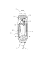
- FIG. 3 is a cross-sectional view showing the configuration of the optical unit.
- the cable 4 for transmitting the signal from the optical unit to the outside is pulled out via the support portion 11 provided on the left side surface portion of the housing 10. It is good also as arrangement
- Each surface of the polygon mirror 3 is divided into two regions by a light projecting / receiving optical partition plate 5 provided on the mirror surface.
- the light receiving optical path through which the laser light reflected by the external measurement object reaches the light receiving lens 51 and the light receiving element 52 is the upper side of the divided mirror surface area. Located in the area.
- the light projecting optical path through which the laser light emitted from the laser 53 is incident on the polygon mirror 3 is located in the lower region of the divided mirror surface regions.
- the laser light receiving / emitting unit 2 includes a light receiving lens 51, a light receiving element 52, a laser 53, and a light projecting lens 54.
- the laser 53 and the light projecting lens 54 constituting the light projecting optical system are arranged above the light receiving lens 51 and the light receiving element 52 constituting the light receiving optical system.
- the laser beam projected from the laser 53 is irradiated to the polygon mirror 3 through the projection lens 54.
- Laser light reflected from the polygon mirror 3 enters the light receiving lens 51.
- the light receiving lens 51 condenses laser light incident from the outside.
- the light receiving element 52 receives the condensed laser light.
- the light receiving element 52 for example, an avalanche photodiode (APD) can be used.
- the laser 53 for example, a laser diode (LD) can be used.
- FIGS. 4A and 4B An encoder 22 is provided above the polygon mirror 3.
- the encoder 22 measures the rotation angle (angular velocity) of the polygon mirror 3.
- the polygon mirror includes a motor 6 therein.
- FIG. 4A is a top view of the polygon mirror 3.
- FIG. 4B is a cross-sectional view of the polygon mirror 3.
- FIG. 5 is a side view for explaining the rotation operation of the optical unit.
- the housing 10 the optical unit 20 swings or rotates about C2 as a rotation axis.
- the measurement range is shown when rotating 45 degrees upward and downward (that is, rotating 90 degrees up and down).
- the rotation axis C2 when the casing 10 swings or rotates may be disposed so as to pass near the position of the center of gravity of the casing 10 (the optical unit 20). Further, for example, when viewed from the side view of FIG. Thereby, when the housing 10 is driven by the external driving device, the swinging or rotating operation can be realized with a smaller driving force.
- FIG. 6 is an external configuration diagram of the three-dimensional distance measuring device.
- the three-dimensional distance measuring device 1 includes an optical unit 20 that swings or rotates about C2 as a rotation axis, and a signal processing unit 30 that is connected to the optical unit 20 via a cable. ing.
- the optical unit 20 and the signal processing unit 30 are configured as separate types, so the optical unit 20 that is a rotating body only needs to be equipped with necessary elements, so the outer shape of the optical unit 20 of the three-dimensional distance measuring device 1 can be reduced. It can be made smaller.
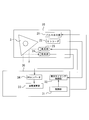
- FIG. 7 is a functional configuration diagram of the three-dimensional distance measuring device.
- the optical unit 20 includes a pulse output unit 21, an encoder 22, a light emitting unit 23, and a light receiving unit 24.
- the signal processing unit 30 includes a control unit 31, a light emission timing control unit 32, a distance calculation unit 33, and an AD converter 34. The elements of the optical unit 20 and the signal processing unit 30 are connected to each other by signal lines included in the cable.
- the pulse output unit 21 outputs a motor pulse corresponding to the motor command value transmitted from the control unit 31 to a motor built in the polygon mirror 3.
- the encoder 22 measures the rotation angle (angular velocity) of the polygon mirror 3.
- the control unit 31 is configured using a CPU.
- the control unit 31 controls the rotation operation of the polygon mirror 3 and controls the light emission of the laser light from the light emitting unit 23.
- the light emission timing control unit 32 determines the rotation angle (angular velocity) of the motor of the polygon mirror 3 from the output of the encoder 22 and controls the light emission timing of the laser light according to the rotation angle (angular velocity) of the motor.
- the distance calculation unit 33 determines the distance to the target object from the timing at which the laser beam is emitted from the light emitting unit 23 and the timing at which the laser beam is received by the light receiving unit 24 based on the principle of time of flight (TOF) of the laser beam. Compute information. Thereby, the three-dimensional distance measuring device 1 acquires the distance image data regarding the measurement object.
- the distance image data is a set of distance data of a plurality of points obtained by two-dimensional scanning in the laser light irradiation direction.
- the AD converter 34 converts the analog signal detected by the light receiving unit 24 into a digital signal.
- the cable configuration between the optical unit 20 and the signal processing unit 30 can be further simplified.
- the configuration in which the AD converter 34 is disposed on the signal processing unit 30 side is illustrated, but the AD converter 34 may be disposed on the optical unit 20 side.
- the AD converter 34 is arranged on the optical unit 20 side, it is possible to reduce the influence of noise generated when passing through the cable.
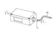
- FIG. 8 is a diagram for explaining a cable configuration for connecting the optical unit and the signal processing unit.
- Various configurations can be adopted as the configuration of the cable taken out from the optical unit 20 that is a rotating body.
- the inside of the support portion 11 may be formed in a hollow structure, and the cable 40 may be taken out along the rotation axis C ⁇ b> 2 of the housing 10.
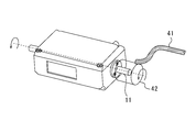
- an electrical connection is made between the signal line of the cable 41 from the signal processing unit 30 and each element of the optical unit 20 using a slip ring mechanism 42 provided at the end of the support unit 11. It is good also as a structure to connect. Thereby, infinite rotation can be realized without worrying about the wiring from the optical unit 20.
- the relationship of the shape of a polygon mirror, a measurement range, etc. is demonstrated.
- the polygon mirror 3 when it has a four-sided mirror shape, it can have a relatively small outer shape, and each has a measurement range of 30 degrees in the left and right directions in front of the polygon mirror 3 ( That is, the measurement range is 60 degrees to the left and right), and scanning from the right direction to the left direction is one scan, and four scans are possible for each rotation of the polygon mirror 3.
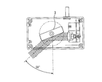
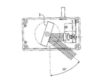
- FIGS. 10A and 10B are diagrams for explaining a measurement situation when a three-sided polygon mirror is used.
- the polygon mirror 3 when the polygon mirror 3 has a three-surface mirror shape, it can have a relatively small outer shape, and each has a measurement range of 45 degrees in the left and right directions in front of the polygon mirror 3. Thus, three scans are possible for each rotation of the polygon mirror 3. Further, as the polygon mirror 3 rotates counterclockwise, the scanning direction of the laser light changes from the state shown in FIG. 10A to the state shown in FIG. 10B.
- FIGS. 11A and 11B are diagrams for explaining a measurement situation when a two-sided polygon mirror is used.
- the polygon mirror 3 when the polygon mirror 3 has a two-sided mirror shape, the polygon mirror 3 can have a relatively small outer shape, and can measure 50 degrees in the left and right directions in front of the polygon mirror 3 respectively. This is a range and can be scanned twice for each rotation of the polygon mirror 3. Further, when the polygon mirror 3 rotates counterclockwise, the scanning direction of the laser light changes from the state shown in FIG. 11A to the state shown in FIG. 11B.
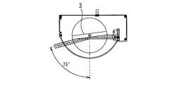
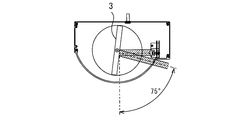
- FIGS. 12A and 12B are diagrams for explaining a measurement situation when a large two-sided polygon mirror is used.
- the measurement range is 75 degrees in the left direction and right direction in front of the mirror 3, and two scans are possible for each rotation of the polygon mirror 3. Further, as the polygon mirror 3 rotates counterclockwise, the scanning direction of the laser light changes from the state shown in FIG. 12A to the state shown in FIG. 12B.
- a double-sided polygon mirror has a small measurement cycle and a large external shape.
- a trihedral polygon mirror has a balanced measurement range and measurement cycle, and a tetrahedral polygon mirror may be used according to the application.
- the shape of the polygon mirror 3 is not limited. However, for example, when a three-surface or four-surface polygon mirror is employed, the outer shape of the optical unit 20 can be reduced, and the measurement range and the measurement cycle can be maximized.
- the optimal scanning angle is 60 degrees for a four-sided shape and 90 degrees for a three-sided shape. there were.
- the relationship between the polygon mirror and the scanning angle is theoretically up to 120 degrees for the six-face shape, 180 degrees for the four-face shape, and 240 degrees for the three-face shape. However, if a compact design is taken into account, only about 1/3 of the theoretical value can be scanned. A larger scanning angle can be secured by enlarging the polygon mirror and expanding the space of the optical system, but it is too large to be mounted on a small robot.
- the size can be further reduced.
- a motor that rotates at a higher speed is required.
- the scanning speed is 10 ms, it is 2000 rpm for the three-surface shape and 3000 rpm for the two-surface shape.
- the life becomes longer if the rotation speed is low. Therefore, it is preferable to use a trihedral polygon from the necessary scanning angle, the number of rotations of the motor, and the space factor.
- an optical unit 20 of the three-dimensional distance measuring device 1 is mounted on the trunk or waist of a legged humanoid robot 100 (hereinafter simply referred to as the robot 100) as an example of a mobile robot.
- the robot 100 is a leg-walking type mobile robot, and has a leg link and an actuator (not shown) for driving the leg link as a moving mechanism.
- the optical unit 20 of the three-dimensional distance measuring device 1 is attached to the waist of the robot 100.
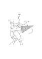
- the front of the robot 100 can be scanned by the optical unit 20 swinging or rotating in the vertical direction with C2 as the rotation axis.
- the optical unit 20 is shown on the outside of the outer cover of the robot 100 for explanation.
- the optical unit 20 can be housed inside the outer cover of the robot 100.
- the optical unit 20 of the three-dimensional distance measuring device 1 is rotatably supported by the trunk of the robot 100 via the support unit 11.
- a motor (not shown) as a drive unit that rotates the optical unit 20 is fixed to the robot 100 such that the rotation axis C2 is in the horizontal direction.
- the optical unit 20 is arranged from the waist to the trunk along the vertical direction, and the optical unit 20 is swung or rotated in the left-right direction with C3 as a rotation axis. You may make it scan ahead.
- the three-dimensional distance measuring device 1 can be used for road surface recognition for the robot 100 to move autonomously.
- the optical unit 20 in a state where the optical unit 20 is not oscillated or rotated, the optical unit 20 has a predetermined inclination angle so that the laser beam is emitted toward the road surface below the front of the robot 100. Located on the waist.
- the distance information of the road surface (each detection point) is acquired for the detection points on the line segment L.
- the three-dimensional distance measuring device 1 when the optical unit 20 is swung or rotated, the three-dimensional distance measuring device 1 is 45 in the vertical direction with the front diagonally downward direction as the reference direction. Oscillate or rotate at a certain degree. Thereby, in the example shown in the figure, a 90-degree measurement range can be realized from the lower direction of the robot 100 in the vertical direction to the horizontal direction.
- FIG. 17 is a diagram illustrating detection points acquired by the three-dimensional distance measuring device 1.
- the distance information to the detection points on the object is acquired for the detection points on the road surface ahead of the robot 100 and the detection points on the obstacle existing on the road surface.
- the three-dimensional distance measuring device 1 is configured to be separated into the optical unit 20 and the signal processing unit 30 connected to the optical unit 20 via wiring.
- the signal processing unit 30 controls the optical unit 20 and calculates distance information.
- the optical unit 20 includes a laser receiving / emitting unit 2 that receives and emits laser light, and the polygon mirror 3 is rotationally driven with an axis orthogonal to the optical axis of the laser light emitted from the laser receiving / emitting unit 2 as a rotation axis.
- the optical unit 20 itself is oscillated or rotated about an axis orthogonal to the rotation axis of the polygon mirror 3 by using an external drive device.
- the configuration of the three-dimensional distance measuring device 1 can be reduced in size, and can be easily mounted in a limited mobile robot mounting space.
- a necessary signal processing circuit is arranged outside the optical unit 20 (sensor), and only the laser light receiving / emitting unit 2 and the polygon mirror 3 are accommodated in the optical unit 20. Further, the projector and the light receiver of the laser light receiving and emitting unit 2 are arranged in the vertical direction with respect to the rotation direction C ⁇ b> 1 of the polygon mirror 3. With such a configuration, it is possible to reduce the number of components to be mounted in the optical unit 20, and it is possible to realize a lightweight and compact three-dimensional distance measuring device 1.
- the three-dimensional distance measuring device 1 can be rotated by a small and inexpensive motor having a low rotational torque. Further, the optical unit 20 can be configured to be thick in the vertical direction, and there is no useless space as a configuration for rotating the optical unit 20, and the three-dimensional distance measuring device 1 having high performance versus space factor can be realized.
- the configuration is such that the polygon mirror 3 in the housing 10, the light receiving element 52 and the laser 53 in the laser light receiving and emitting unit 2 are arranged, and thus the wiring
- the laser receiving / emitting unit 2 and the polygon mirror 3 can be arranged on the same member without complicating the handling of the laser beam.
- a legged mobile robot has been described as an example of the robot.
- the configuration of the mobile robot is not particularly limited as long as a three-dimensional distance measuring device can be mounted. Absent.
- a robot having a configuration that moves by driving wheels may be used.
- the present invention can be used for, for example, a three-dimensional distance measuring device and a mobile robot that acquire distance information to an object in the outside world.
- 1 3D ranging device 2 Laser receiving and emitting unit, 3 Polygon mirror, 4 cables, 5 Transmitter / receiver optical divider, 6 motor, 11 Support part, C1, C2, C3 rotation axis, 20 Optics, 21 Pulse output section, 22 Encoder, 23 Light emitting part, 24 light receiving unit, 30 signal processor, 31 control unit, 32 light emission timing controller, 33 Distance calculator, 34 AD converter, 40, 41 cable, 42 slip ring mechanism, 51 light receiving lens, 52 light receiving element, 53 laser, 54 Projection lens 100 robot
Landscapes
- Engineering & Computer Science (AREA)
- Physics & Mathematics (AREA)
- Computer Networks & Wireless Communication (AREA)
- General Physics & Mathematics (AREA)
- Radar, Positioning & Navigation (AREA)
- Remote Sensing (AREA)
- Electromagnetism (AREA)
- Optical Radar Systems And Details Thereof (AREA)
- Measurement Of Optical Distance (AREA)
Abstract
小型化及び移動ロボットに容易に搭載可能な三次元測距装置を提供する。三次元測距装置1は、光学部20と信号処理部30を備える。光学部20は、レーザ光を受光及び発光するレーザ受発光部2と、複数のミラー面を有し、レーザ受発光部2から発光するレーザ光の光軸と直交する軸C1を回転軸として回転駆動され、レーザ受発光部2から照射されたレーザ光をミラー面で反射して対象物に照射すると共に、対象物から反射されたレーザ光を反射してレーザ受発光部2に導くポリゴンミラー3と、を有する。信号処理部30は、ポリゴンミラー3の回転制御とレーザ受発光部2からのレーザ光の照射タイミングの制御を行うと共に、レーザ光の受光タイミングから対象物までの距離情報を演算する。光学部20は、回転軸C1に直交する軸を回転軸C2として、外部駆動装置を用いて揺動又は回転動作される。
Description
本発明は、例えば外界の対象物までの距離情報を取得する三次元測距装置及び移動ロボットに関する。
環境内を自律的に移動する移動ロボットは、外界情報を認識するため、三次元空間を計測することが重要となる。三次元計測に用いるセンサとしては、レーザレンジセンサや、ステレオカメラや、デプスイメージャーなどが知られている。
特許文献1には、レーザレンジセンサを用いて、三次元空間を測定する手法が開示されている。特許文献1に開示される手法では、左右方向にレーザ光を走査するレーザレンジセンサを移動ロボットに搭載し、搭載したセンサを上下方向(ピッチ方向)に揺動することで、移動ロボット前方の環境の三次元計測を可能とする。
また、本発明に関連する他の技術として、特許文献2乃至5には、ポリゴンミラーを用いて水平方向を走査させると共に、ポリゴンミラー全体や他のミラーをモータにより回転駆動制御することで垂直方向を走査させるレーザ距離測定装置が開示されている。
しかしながら、レーザレンジセンサを用いた手法は、他の種類のセンサを用いた手法と比較して距離精度や外乱光に強いという利点を有しているものの、センサ自体の外形が大きなものであるという問題がある。
また、特許文献1に開示される手法では、外形の大きなレーザレンジセンサ自体を揺動させる構成であるため、三次元計測に必要とする機構が大きなものとなってしまう。
特許文献2乃至5に記載のレーザ距離測定装置によれば、比較的速い走査速度を必要とする水平方向の走査にはポリゴンミラーを使用し、比較的遅い走査速度でも構わない垂直軸方向の走査にはポリゴンミラー全体や他のミラーをモータにより回転制御することで、3次元の距離画像信号を取得することができる。しかし、特許文献2乃至5に記載の技術には、以下に説明する問題がある。
特許文献2には、レーザ光の発光部と受光部とを光軸上に対峙するように配置し、回転駆動するポリゴンミラーにレーザ光が照射され、ポリゴンミラーのミラー面のひとつでレーザ光を反射して対象物に照射すると共に、対象物によるレーザ光の反射を異なるミラー面で反射して受光部に導くレーザ距離測定装置が開示されている。
しかし、特許文献2に開示されるレーザ距離測定装置では、それぞれ異なるミラー面を用いて、発光部から入射するレーザ光と受光部へと反射して導かれるレーザ光とを入反射するものであり、受光部及び発光部の配置構成から、小型化に制約がある。また、特許文献2に開示されるレーザ距離測定装置では、ポリゴンミラーのみを搭載した把持具自体を所定の角度範囲で往復揺動させるのみであり、発光部を含む構成全体を揺動させることは開示していないものである。このため、三次元測距装置の構成として小型化を図ると共に、限られた移動ロボットの搭載スペースに対しても容易に搭載可能とするものではない。
特許文献3及び5に開示された技術では、ポリゴンミラーや他のミラーを回転駆動させるモータが方持ち構成であるため、水平方向のアクチュエータの回転バランスをとるのが難しい。特に、装置に対して振動が加わると、共振により回転バランスが変化してしまうため、安定した3次元データを取得することができない。従って、例えば振動が大きなロボットなどに対しては、このままでは搭載させることができない。
また、特許文献4及び5に開示された技術では、ミラー・スキャナ光学系と投受光部とを分けた構成とするため、水平方向の回転に対して大きなスペースを確保する必要があり、コンパクトな設計が難しい。さらに、距離計の場合には、感度を上げるためにはできるだけ受光レンズを大きくする必要があるため、光学系を小さくすることができない。
また、特許文献4及び5に開示された技術では、ポリゴンミラーに加えて他のミラーを必要とし、投受光光学系において4回のミラー反射が必要である。レーザ距離計では、使用者に不快感を与えないため、一般的に800~1000nmの波長域の目に見えない赤外光を使用する。安価なミラーを使えば95%程度の反射率しか実現できず、4回の反射により効率が80%にまで低下する。一方で、反射率99%の金のミラーを使用すれば、高価となってしまう。
このように従来技術では、レーザ光を走査するための構造やミラーの形状が最適でなく、また、光学部と信号処理部とが一体的に形成されているものであった。このため、三次元計測に必要とする機構全てを移動ロボットの内部に搭載することが困難である。また、移動ロボットの外形カバーの内側に収めることが可能な三次元測距装置が強く求められている。
従って、本発明の目的は、小型化を図ると共に、限られた移動ロボットの搭載スペースに対しても容易に搭載可能な三次元測距装置及びその構成を搭載した移動ロボットを提供することにある。
本発明に係る三次元測距装置は、外界の対象物までの距離情報を取得する三次元測距装置であって、光学部と、前記光学部と配線を介して接続される信号処理部と、を備え、前記光学部は、レーザ光を受光及び発光するレーザ受発光部と、複数のミラー面を有し、前記レーザ受発光部から発光するレーザ光の光軸と直交する軸を回転軸として回転駆動され、前記レーザ受発光部から照射されたレーザ光を前記ミラー面で反射して対象物に照射すると共に、対象物から反射されたレーザ光を反射して前記レーザ受発光部に導くポリゴンミラーと、を有し、前記信号処理部は、前記ポリゴンミラーの回転制御と前記レーザ受発光部からのレーザ光の照射タイミングの制御を行うと共に、レーザ光の受光タイミングから対象物までの距離情報を演算し、前記光学部は、前記ポリゴンミラーの回転軸に直交する軸を回転軸として、外部駆動装置を用いて揺動又は回転動作されることを特徴とする。
このように、三次元測距装置を、光学部と、光学部と配線を介して接続される信号処理部とに分離して構成し、信号処理部では光学部の制御及び距離情報の演算を行うものとして、光学部では、レーザ光を受光及び発光するレーザ受発光部を含むと共に、ポリゴンミラーの配置をレーザ受発光部から発光するレーザ光の光軸と直交する軸を回転軸として回転駆動される配置とし、外部駆動装置を用いて、ポリゴンミラーの回転軸に直交する軸を回転軸として光学部自体を揺動又は回転動作される構成としたことで、三次元測距装置の構成の小型化を図ると共に、限られた移動ロボットの搭載スペースに対しても容易に搭載することができる。
また、前記レーザ受発光部及び前記ポリゴンミラーを前記光学部の回転軸上に配置するようにしてもよい。これにより、光学部を揺動又は回転動作させる際に、光学部の回転径をより小さくすることができる。
さらにまた、前記光学部は、前記ポリゴンミラーの回転軸に直交する軸であって、前記光学部の略重心位置を通過する軸を回転軸として、前記外部駆動装置を用いて揺動又は回転動作されるようにしてもよい。これにより、光学部を揺動又は回転動作させる際には、より少ない駆動力により、揺動又は回転動作を実現することができる。
また、前記ポリゴンミラーは、三面又は四面のミラー面を有するようにしてもよい。これにより、光学部の外形を小さくすると共に、計測範囲及び計測周期を最大化することができる。
さらにまた、前記光学部は、前記外部駆動装置に回転自在に支持される支持部であって、中空状に形成された支持部を側面に備え、前記光学部からの配線は、前記支持部内を通って前記信号処理部に接続されるようにしてもよい。これにより、光学部からの配線を気にせずに、無限回転を実現することができる。
さらにまた、前記光学部は、前記外部駆動装置に回転自在に支持される支持部であって、スリップリングが端部に設けられた支持部を側面に備え、前記光学部からの配線は、前記スリップリングを介して前記信号処理部に電気的に接続されるようにしてもよい。これにより、光学部からの配線を気にせずに、無限回転を実現することができる。
また、前記信号処理部は、前記レーザ受発光部で検出したアナログ信号をデジタル信号に変換するADコンバータを有するようにしてもよい。ADコンバータを信号処理部側に配置することで、信号処理部と光学部間のケーブル構成をより簡素化することができる。
また、前記光学部は、前記レーザ受発光部で検出したアナログ信号をデジタル信号に変換するADコンバータを有するようにしてもよい。ADコンバータを光学部側に配置することで、配線で発生するノイズの影響を低減することができる。
さらにまた、前記ポリゴンミラーは、当該ポリゴンミラーを回転動作させる駆動部を内蔵するようにしてもよい。これにより、より小型化を図ることができる。
本発明に係る移動ロボットは、外界の対象物までの距離情報を取得する移動ロボットであって、光学部と、前記光学部と配線を介して接続される信号処理部と、前記光学部を揺動又は回転動作させる駆動部と、を備え、前記光学部は、レーザ光を受光及び発光するレーザ受発光部と、複数のミラー面を有し、前記レーザ受発光部から発光するレーザ光の光軸と直交する軸を回転軸として回転駆動され、前記レーザ受発光部から照射されたレーザ光を前記ミラー面で反射して対象物に照射すると共に、対象物から反射されたレーザ光を反射して前記レーザ受発光部に導くポリゴンミラーと、を有し、前記信号処理部は、前記ポリゴンミラーの回転制御と前記レーザ受発光部からのレーザ光の照射タイミングの制御を行うと共に、レーザ光の受光タイミングから対象物までの距離情報を演算し、前記駆動部は、前記ポリゴンミラーの回転軸に直交する軸を回転軸として、前記光学部を揺動又は回転動作させることを特徴とするものである。
これにより、小型化かつ少ない搭載スペースに対しても容易に搭載可能な三次元測距装置の構成を備えた移動ロボットを実現することができる。
本発明によれば、小型化を図ると共に、限られた移動ロボットの搭載スペースに対しても容易に搭載可能な三次元測距装置及びその構成を搭載した移動ロボットを提供することができる。
実施の形態1.
以下、図面を参照して本発明の実施の形態について説明する。図1は、本実施の形態に係る三次元測距装置の光学部を示す斜視図である。後述するように、三次元測距装置1は、光学部20と信号処理部30とから構成され、光学部20の各機能は、筐体10に備えられた各要素により実現される。
以下、図面を参照して本発明の実施の形態について説明する。図1は、本実施の形態に係る三次元測距装置の光学部を示す斜視図である。後述するように、三次元測距装置1は、光学部20と信号処理部30とから構成され、光学部20の各機能は、筐体10に備えられた各要素により実現される。
筐体10の左右の側面部には、支持部11が設けられている。筐体10は、支持部11を介して、モータなどの外部駆動装置(不図示)に回転自在に取り付けられている。筐体10は、外部駆動装置の駆動により、C2を回転軸として所定の範囲内で揺動又は回転動作する。また、筐体10の前面には光学部20へのレーザ光入出射用の窓部が形成されている。窓部には平板ガラスなどの光学素子を用いたレーザ透過部材が固定されている。
筐体10は、レーザ受発光部2と、ポリゴンミラー3と、を内部に備えている。レーザ受発光部2とポリゴンミラー3は、レーザ受発光部2の光軸とポリゴンミラー3の回転軸とが互いに直交するように配置されている。
レーザ受発光部2は、ポリゴンミラー3に向けてレーザ光を照射すると共に、ポリゴンミラー3から反射したレーザ光を受光する。レーザ受発光部2の詳細については後述する。
ポリゴンミラー3は、モータ(不図示)を内蔵した回転ポリゴンミラーである。ポリゴンミラー3は、C1を回転軸として回転動作する。ポリゴンミラー3は、回転軸C1に対して所定の角度に位置づけられた複数のミラー面を有している。なお、図に示す例では、ポリゴンミラー3は四面ミラーとして説明しているが、後述するように、四面以外のポリゴンミラーとしてもよく、次の図2などでは、三面ミラーである場合を例に説明する。
レーザ受発光部2から照射されたレーザ光は、ポリゴンミラー3により反射され、筐体10前面の窓部を通過して外部へと照射される。外部の測定対象物により反射されたレーザ光は、筐体10前面の窓部を通過してポリゴンミラー3へと入射し、ポリゴンミラー3により反射されたレーザ光がレーザ受発光部2へと入射する。ここで、レーザ受発光部2からのレーザ光が入射するポリゴンミラー3のミラー面と、外部の対象物から反射したレーザ光が入射するポリゴンミラー3のミラー面とは、同一のミラー面となる。
ポリゴンミラー3がC1を回転軸として回転動作することで、筐体10前面の左右方向にわたって、レーザ受発光部2からのレーザ光が走査される。さらに、筐体10がC2を回転軸として揺動又は回転動作することで、筐体10前面の上下方向(ピッチ方向)にわたって、レーザ受発光部2からのレーザ光が走査される。このようにポリゴンミラー3を光学部20内に配置し、光学部20をピッチ方向に揺動又は回転動作することで、筐体10の前面の所定の三次元領域にわたって、レーザ受発光部2からのレーザ光を走査させることができる。これにより、小型、かつ、回転半径の小さな光学部20を用いて三次元測距装置1を実現することができる。
図2は、光学部の構成を示す上面図である。
ポリゴンミラー3及びレーザ受発光部2は、回転軸C2方向に沿って配置される。図2に示す例では、ポリゴンミラー3の回転軸C1と、レーザ受発光部2を含むケースとが、筐体10の回転軸C2上に位置するように配置されている。このように、回転軸C2に対して、ポリゴンミラー3及びレーザ受発光部2の配置を規定することで、筐体10を揺動又は回転動作させる際には、回転軸C2を中心とする光学部20の回転半径を小さくすることができる。
ポリゴンミラー3及びレーザ受発光部2は、回転軸C2方向に沿って配置される。図2に示す例では、ポリゴンミラー3の回転軸C1と、レーザ受発光部2を含むケースとが、筐体10の回転軸C2上に位置するように配置されている。このように、回転軸C2に対して、ポリゴンミラー3及びレーザ受発光部2の配置を規定することで、筐体10を揺動又は回転動作させる際には、回転軸C2を中心とする光学部20の回転半径を小さくすることができる。
なお、図に示す例では、レーザ受発光部2から照射されて光学部20の外部に出射するレーザ光を破線により示している。また、光学部20の外部から内部に入射されるレーザ光は広がりを持つため、そのレーザ光はハッチングにより示している。
図3は、光学部の構成を示す断面図である。尚、図に示した例では、光学部からの信号を外部へと伝達するためのケーブル4が、筐体10の左側の側面部に設けられた支持部11を介して引き出されているが、右側の側面部に設けられた支持部11から引き出される配置としてもよい。
ポリゴンミラー3は、ミラー面に設けられた投受光光学仕切り板5により、各面が2つの領域に分割されている。図に示す例では、外部の測定対象物により反射されたレーザ光が、受光レンズ51及び受光素子52へと至る際に通過する受光光学経路は、分割されたミラー面の領域のうち、上側の領域に位置する。レーザ53から照射されたレーザ光が、ポリゴンミラー3に入射する際に通過する投光光学経路は、分割されたミラー面の領域のうち、下側の領域に位置する。
レーザ受発光部2は、受光レンズ51と、受光素子52と、レーザ53と、投光レンズ54と、を備えている。図に示す例では、投光光学系を構成するレーザ53及び投光レンズ54は、受光光学系を構成する受光レンズ51及び受光素子52の上方に配置されている。レーザ53から投光されたレーザ光が、投光レンズ54を介してポリゴンミラー3に照射される。ポリゴンミラー3から反射されたレーザ光が、受光レンズ51へと入射される。受光レンズ51は、外部から入射されたレーザ光を集光する。受光素子52は、集光されたレーザ光を受光する。受光素子52としては、例えば、アバランシェ・フォトダイオード(APD)を用いることができる。レーザ53としては、例えば、レーザダイオード(LD)を用いることができる。
ポリゴンミラー3の上方には、エンコーダ22が設けられている。エンコーダ22は、ポリゴンミラー3の回転角度(角速度)を計測する。また、ポリゴンミラーは、図4A、4Bに示すように、内部にモータ6を内蔵している。図4Aは、ポリゴンミラー3の上面図である。また、図4Bは、ポリゴンミラー3の断面図である。ポリゴンミラー3の内部に駆動部としてのモータを備える構成とすることで、より小型化を図ることができる。
図5は、光学部の回転動作を説明するための側面図である。
上述したように、筐体10(光学部20)は、C2を回転軸として揺動又は回転動作する。図5に示す例では、上方向及び下方向にそれぞれ45度回転させる場合(すなわち上下に90度回転させる場合)の計測範囲を示している。なお、筐体10が揺動又は回転動作する際の回転軸C2は、筐体10(光学部20)の重心位置付近を通過するように配置してもよい。また、例えば図5の側面図で見た場合に、筐体10の側面の中心部を通るように配置してもよい。これにより、外部駆動装置により筐体10を駆動する際には、より少ない駆動力により、揺動又は回転動作を実現することができる。
上述したように、筐体10(光学部20)は、C2を回転軸として揺動又は回転動作する。図5に示す例では、上方向及び下方向にそれぞれ45度回転させる場合(すなわち上下に90度回転させる場合)の計測範囲を示している。なお、筐体10が揺動又は回転動作する際の回転軸C2は、筐体10(光学部20)の重心位置付近を通過するように配置してもよい。また、例えば図5の側面図で見た場合に、筐体10の側面の中心部を通るように配置してもよい。これにより、外部駆動装置により筐体10を駆動する際には、より少ない駆動力により、揺動又は回転動作を実現することができる。
図6は、三次元測距装置の外観構成図である。
図6に示すように、三次元測距装置1は、C2を回転軸として揺動又は回転動作する光学部20と、光学部20とケーブルを介して接続される信号処理部30と、を備えている。光学部20と信号処理部30とを分離型として構成することで、回転体である光学部20は必要な要素のみを搭載すれば済むため、三次元測距装置1の光学部20の外形をより小型化することができる。
図6に示すように、三次元測距装置1は、C2を回転軸として揺動又は回転動作する光学部20と、光学部20とケーブルを介して接続される信号処理部30と、を備えている。光学部20と信号処理部30とを分離型として構成することで、回転体である光学部20は必要な要素のみを搭載すれば済むため、三次元測距装置1の光学部20の外形をより小型化することができる。
図7は、三次元測距装置の機能構成図である。
光学部20は、パルス出力部21と、エンコーダ22と、発光部23と、受光部24とを備えている。信号処理部30は、制御部31と、発光タイミング制御部32と、距離演算部33と、ADコンバータ34と、を備えている。光学部20と信号処理部30の各要素は、ケーブルに含まれる信号線により互いに接続されている。
光学部20は、パルス出力部21と、エンコーダ22と、発光部23と、受光部24とを備えている。信号処理部30は、制御部31と、発光タイミング制御部32と、距離演算部33と、ADコンバータ34と、を備えている。光学部20と信号処理部30の各要素は、ケーブルに含まれる信号線により互いに接続されている。
パルス出力部21は、制御部31から送信されるモータ指令値に応じたモータパルスを、ポリゴンミラー3に内蔵されたモータに出力する。エンコーダ22は、ポリゴンミラー3の回転角度(角速度)を計測する。
制御部31は、CPUを用いて構成される。制御部31は、ポリゴンミラー3の回転動作を制御すると共に、発光部23からのレーザ光の発光を制御する。発光タイミング制御部32は、エンコーダ22の出力からポリゴンミラー3のモータの回転角度(角速度)を判定し、モータの回転角度(角速度)に応じて、レーザ光の発光タイミングを制御する。
距離演算部33は、発光部23からレーザ光を発光したタイミングと、受光部24でレーザ光を受光したタイミングとから、レーザ光の飛行時間の原理(TOF)に基づいて、対象物体までの距離情報を演算する。これにより、三次元測距装置1は、測定対象物に関する距離画像データを取得する。ここで距離画像データとは、レーザ光の照射方向を2次元走査することによって得られる複数点の距離データの集合である。
ADコンバータ34は、受光部24で検出したアナログ信号をデジタル信号に変換する。ADコンバータ34を信号処理部30側に配置することで、光学部20と信号処理部30との間のケーブル構成をより簡素化することができる。尚、本実施の形態では、ADコンバータ34を信号処理部30側に配置した構成を例示するが、ADコンバータ34を光学部20側に配置する構成としてもよい。ADコンバータ34を光学部20側に配置した場合には、ケーブルを通過する際に発生するノイズの影響を低減することができる。
図8は、光学部と信号処理部とを接続するケーブル構成を説明するための図である。回転体である光学部20から取り出されるケーブルの構成としては、さまざまな構成を採用することができる。例えば、図8に示すように、支持部11の内部を中空構造に形成し、筐体10の回転軸C2に沿ってケーブル40を取り出す構成としてもよい。また、図9に示すように、信号処理部30からのケーブル41の信号線と、光学部20の各要素との間を、支持部11の端部に設けたスリップリング機構42を用いて電気的に接続する構成としてもよい。これにより、光学部20からの配線を気にせずに、無限回転を実現することができる。
ここで、図1、及び図10A、B乃至12A、Bを参照して、ポリゴンミラーの形状や計測範囲などの関係を説明する。
図1に示したように、ポリゴンミラー3を四面のミラー形状とした場合には、比較的小さな外形とすることができ、ポリゴンミラー3前方の左方向及び右方向にそれぞれ30度の計測範囲(すなわち、左右に60度の計測範囲)であり、右方向から左方向にわたっての走査を1回のスキャンとして、ポリゴンミラー3の一回転ごとに4回のスキャンが可能である。
図1に示したように、ポリゴンミラー3を四面のミラー形状とした場合には、比較的小さな外形とすることができ、ポリゴンミラー3前方の左方向及び右方向にそれぞれ30度の計測範囲(すなわち、左右に60度の計測範囲)であり、右方向から左方向にわたっての走査を1回のスキャンとして、ポリゴンミラー3の一回転ごとに4回のスキャンが可能である。
図10A、10Bは、三面ポリゴンミラーを用いた場合の計測状況を説明するための図である。
図10A、10Bに示すように、ポリゴンミラー3を三面のミラー形状とした場合には、比較的小さな外形とすることができ、ポリゴンミラー3前方の左方向及び右方向にそれぞれ45度の計測範囲であり、ポリゴンミラー3の一回転ごとに3回のスキャンが可能である。また、ポリゴンミラー3が反時計回りに回転することで、図10Aに示した状態から図10Bに示した状態へとレーザ光の走査方向が変化する。
図10A、10Bに示すように、ポリゴンミラー3を三面のミラー形状とした場合には、比較的小さな外形とすることができ、ポリゴンミラー3前方の左方向及び右方向にそれぞれ45度の計測範囲であり、ポリゴンミラー3の一回転ごとに3回のスキャンが可能である。また、ポリゴンミラー3が反時計回りに回転することで、図10Aに示した状態から図10Bに示した状態へとレーザ光の走査方向が変化する。
図11A、11Bは、二面ポリゴンミラーを用いた場合の計測状況を説明するための図である。
図11A、11Bに示すように、ポリゴンミラー3を二面のミラー形状とした場合には、比較的小さな外形とすることができ、ポリゴンミラー3前方の左方向及び右方向にそれぞれ50度の計測範囲であり、ポリゴンミラー3の一回転ごとに2回のスキャンが可能である。また、ポリゴンミラー3が反時計回りに回転することで、図11Aに示した状態から図11Bに示した状態へとレーザ光の走査方向が変化する。
図11A、11Bに示すように、ポリゴンミラー3を二面のミラー形状とした場合には、比較的小さな外形とすることができ、ポリゴンミラー3前方の左方向及び右方向にそれぞれ50度の計測範囲であり、ポリゴンミラー3の一回転ごとに2回のスキャンが可能である。また、ポリゴンミラー3が反時計回りに回転することで、図11Aに示した状態から図11Bに示した状態へとレーザ光の走査方向が変化する。
図12A、12Bは、大型の二面ポリゴンミラーを用いた場合の計測状況を説明するための図である。
図12A、12Bに示すように、ポリゴンミラー3を図11A、11Bに示した二面のポリゴンミラーと比較してより大型の二面ポリゴンミラー形状とした場合には、外形は大きくなるものの、ポリゴンミラー3前方の左方向及び右方向にそれぞれ75度の計測範囲となり、ポリゴンミラー3の一回転ごとに2回のスキャンが可能である。また、ポリゴンミラー3が反時計回りに回転することで、図12Aに示した状態から図12Bに示した状態へとレーザ光の走査方向が変化する。
図12A、12Bに示すように、ポリゴンミラー3を図11A、11Bに示した二面のポリゴンミラーと比較してより大型の二面ポリゴンミラー形状とした場合には、外形は大きくなるものの、ポリゴンミラー3前方の左方向及び右方向にそれぞれ75度の計測範囲となり、ポリゴンミラー3の一回転ごとに2回のスキャンが可能である。また、ポリゴンミラー3が反時計回りに回転することで、図12Aに示した状態から図12Bに示した状態へとレーザ光の走査方向が変化する。
このように、二面形状のポリゴンミラーでは計測周期が小さく、また、外形が大きなものとなることがある。これに対して、三面形状のポリゴンミラーでは、計測範囲や計測周期のバランスがとれており、また、四面形状のポリゴンミラーでは、用途に応じて使用すればよい。従って、ポリゴンミラー3の形状は限定されないが、例えば三面又は四面形状のポリゴンミラーを採用した場合には、光学部20の外形を小さくすると共に、計測範囲及び計測周期を最大化することができる。
コンパクト設計で広い走査角を実現するためには、三面又は四面形状のポリゴンミラーを採用すると好適である。コンパクトなポリゴンミラー光学系を実現しようとすれば、投受光器が影となって光路をふさぐため、走査角度は、四面形状の場合には60度、三面形状の場合には90度が最適であった。
ポリゴンミラーと走査角度の関係は、理論値では、六面形状では最大120度、四面形状では180度、三面形状では240度まで取ることができる。しかし、コンパクト設計を考慮すれば理論値の1/3程度しか走査はできない。ポリゴンミラーを大きくし、光学系のスペースを広げればもう少し大きな走査角度を確保できるが、小型ロボットに搭載するには大きすぎるものとなる。
一方で、ポリゴンミラーを二面形状とすればより小型化が可能であるが、同一の走査速度を維持するためには、さらに高速回転のモータが必要である。例えば、走査速度が10msの場合、三面形状では2000rpm、二面形状では3000rpmとなる。長期間安定して連続使用するロボットの場合には、回転数が低ければ寿命が長くなる。従って、必要な走査角度と、モータの回転数と、スペースファクタとから、三面形状のポリゴンとすると好適である。
図13乃至16を参照して、三次元測距装置1を移動ロボットに搭載した場合の、計測のようすを説明する。図では、移動ロボットの一例としての脚式ヒューマノイドロボット100(以下、単にロボット100と称する。)に対して、その胴体部又は腰部に三次元測距装置1の光学部20を搭載している。なお、ロボット100は、脚歩行型の移動ロボットであり、移動機構として脚リンク及びこれを駆動するアクチュエータ(不図示)を有している。
例えば図13に示すように、ロボット100の腰部に対して三次元測距装置1の光学部20が取り付けられる。光学部20がC2を回転軸として上下方向に揺動又は回転動作することで、ロボット100の前方を走査することができる。なお、図では、説明のため光学部20をロボット100の外形カバーの外側に示しているが、本実施の形態に係る三次元測距装置1の光学部20は小型かつ薄型であるために、ロボット100の外形カバーの内側に光学部20を収納することが可能である。さらに、三次元測距装置1の光学部20は、支持部11を介して、ロボット100の体幹部に回転自在に支持される。光学部20を回転駆動させる駆動部としてのモータ(不図示)は、回転軸C2が水平方向となるようにロボット100に固定されている。
また、例えば図14に示すように、光学部20を鉛直方向に沿って腰部から胴部にかけて配置し、C3を回転軸として光学部20を左右方向に揺動又は回転動作することで、ロボット100の前方を走査するようにしてもよい。
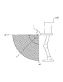
三次元測距装置1は、ロボット100が自律移動するための路面認識に用いることができる。例えば、図15に示すように、光学部20を揺動又は回転動作させない状態において、ロボット100の前方下方の路面に向けてレーザ光が照射されるように、所定の傾斜角度で光学部20が腰部に配置されている。図に示す状態では、線分L上の検出点について、路面(各検出点)の距離情報を取得する。
また、例えば、図16の側面視に示すように、光学部20を揺動又は回転動作させる場合には、三次元測距装置1は、前方斜め下方向を基準方向として、上下方向にそれぞれ45度の揺動又は回転動作を行う。これにより、図に示す例では、ロボット100の鉛直方向下方向から水平方向へとわたって、90度の計測範囲を実現することができる。
図17は、三次元測距装置1により取得される検出点を例示する図である。図に示す例では、ロボット100の前方の路面上の検出点と、路面上に存在する障害物上の検出点について、それら対象物上の検出点までの距離情報が取得される。
以上説明したように、本発明によれば、三次元測距装置1を、光学部20と、光学部20と配線を介して接続される信号処理部30とに分離して構成する。信号処理部30では、光学部20の制御及び距離情報の演算を行う。光学部20では、レーザ光を受光及び発光するレーザ受発光部2を含むと共に、ポリゴンミラー3の配置をレーザ受発光部2から発光するレーザ光の光軸と直交する軸を回転軸として回転駆動される配置とし、外部駆動装置を用いて、ポリゴンミラー3の回転軸に直交する軸を回転軸として光学部20自体を揺動又は回転動作される構成としている。これにより、三次元測距装置1の構成の小型化を図ると共に、限られた移動ロボットの搭載スペースに対しても容易に搭載することができる。
また、本発明によれば、必要な信号処理回路を光学部20(センサ)の外部に配置し、レーザ受発光部2とポリゴンミラー3のみを光学部20内に収容している。また、レーザ受発光部2の投光器及び受光器を、ポリゴンミラー3の回転方向C1に対して上下方向に配置している。このような構成により、光学部20内に搭載する部品を少なくすることができ、軽量かつコンパクトな三次元測距装置1を実現することができる。
さらに、三次元測距装置1は、光学部20の回転中心と重心とが一致しているため、回転トルクの低い小さくて安価なモータにより回転させることができる。また、光学部20を縦方向に厚く構成することができ、光学部20を回転させる構成として無駄なスペースがなくなり、性能対スペースファクタの高い三次元測距装置1を実現できる。
また、従来技術では、ポリゴンミラーと光源とを同一の部材上に配置して回転させる構成とした場合には、配線の取り回しが複雑になるものであった。これに対して、本発明によれば、上述したようにして、筐体10内部のポリゴンミラー3やレーザ受発光部2内の受光素子52及びレーザ53などを配置する構成としたことで、配線の取り回しを複雑化させずに、レーザ受発光部2とポリゴンミラー3とを同一の部材上に配置することができる。
なお、本発明は上述した実施の形態に限られたものではなく、趣旨を逸脱しない範囲で適宜変更することが可能である。
例えば、上述した実施の形態においては、ロボットとして脚式の移動ロボットを例に説明したが、移動ロボットの構成としては、三次元測距装置を搭載可能なものであれば特に限定されるものではない。例えば、車輪を駆動することで移動する構成を備えるロボットでもよい。
例えば、上述した実施の形態においては、ロボットとして脚式の移動ロボットを例に説明したが、移動ロボットの構成としては、三次元測距装置を搭載可能なものであれば特に限定されるものではない。例えば、車輪を駆動することで移動する構成を備えるロボットでもよい。
本発明は、例えば外界の対象物までの距離情報を取得する三次元測距装置及び移動ロボットに利用できる。
1 三次元測距装置、
2 レーザ受発光部、
3 ポリゴンミラー、
4 ケーブル、
5 投受光光学仕切り板、
6 モータ、
11 支持部、
C1、C2、C3 回転軸、
20 光学部、
21 パルス出力部、
22 エンコーダ、
23 発光部、
24 受光部、
30 信号処理部、
31 制御部、
32 発光タイミング制御部、
33 距離演算部、
34 ADコンバータ、
40、41 ケーブル、
42 スリップリング機構、
51 受光レンズ、
52 受光素子、
53 レーザ、
54 投光レンズ
100 ロボット
2 レーザ受発光部、
3 ポリゴンミラー、
4 ケーブル、
5 投受光光学仕切り板、
6 モータ、
11 支持部、
C1、C2、C3 回転軸、
20 光学部、
21 パルス出力部、
22 エンコーダ、
23 発光部、
24 受光部、
30 信号処理部、
31 制御部、
32 発光タイミング制御部、
33 距離演算部、
34 ADコンバータ、
40、41 ケーブル、
42 スリップリング機構、
51 受光レンズ、
52 受光素子、
53 レーザ、
54 投光レンズ
100 ロボット
Claims (18)
- 外界の対象物までの距離情報を取得する三次元測距装置であって、
光学部と、前記光学部と配線を介して接続される信号処理部と、を備え、
前記光学部は、
レーザ光を受光及び発光するレーザ受発光部と、
複数のミラー面を有し、前記レーザ受発光部から発光するレーザ光の光軸と直交する軸を回転軸として回転駆動され、前記レーザ受発光部から照射されたレーザ光を前記ミラー面で反射して対象物に照射すると共に、対象物から反射されたレーザ光を反射して前記レーザ受発光部に導くポリゴンミラーと、を有し、
前記信号処理部は、
前記ポリゴンミラーの回転制御と前記レーザ受発光部からのレーザ光の照射タイミングの制御を行うと共に、レーザ光の受光タイミングから対象物までの距離情報を演算し、
前記光学部は、前記ポリゴンミラーの回転軸に直交する軸を回転軸として、外部駆動装置を用いて揺動又は回転動作される
ことを特徴とする三次元測距装置。 - 前記レーザ受発光部及び前記ポリゴンミラーを前記光学部の回転軸上に配置する
ことを特徴とする請求項1に記載の三次元測距装置。 - 前記光学部は、前記ポリゴンミラーの回転軸に直交する軸であって、前記光学部の略重心位置を通過する軸を回転軸として、前記外部駆動装置を用いて揺動又は回転動作される
ことを特徴とする請求項1又は2に記載の三次元測距装置。 - 前記ポリゴンミラーは、三面又は四面のミラー面を有する
ことを特徴とする請求項1乃至3いずれか1項に記載の三次元測距装置。 - 前記光学部は、前記外部駆動装置に回転自在に支持される支持部であって、中空状に形成された支持部を側面に備え、
前記光学部からの配線は、前記支持部内を通って前記信号処理部に接続される
ことを特徴とする請求項1乃至4いずれか1項に記載の三次元測距装置。 - 前記光学部は、前記外部駆動装置に回転自在に支持される支持部であって、スリップリングが端部に設けられた支持部を側面に備え、
前記光学部からの配線は、前記スリップリングを介して前記信号処理部に電気的に接続される
ことを特徴とする請求項1乃至4いずれか1項に記載の三次元測距装置。 - 前記信号処理部は、前記レーザ受発光部で検出したアナログ信号をデジタル信号に変換するADコンバータを有する
ことを特徴とする請求項1乃至6いずれか1項に記載の三次元測距装置。 - 前記光学部は、前記レーザ受発光部で検出したアナログ信号をデジタル信号に変換するADコンバータを有する
ことを特徴とする請求項1乃至6いずれか1項に記載の三次元測距装置。 - 前記ポリゴンミラーは、当該ポリゴンミラーを回転動作させる駆動部を内蔵する
ことを特徴とする請求項1乃至8いずれか1項に記載の三次元測距装置。 - 外界の対象物までの距離情報を取得する移動ロボットであって、
光学部と、前記光学部と配線を介して接続される信号処理部と、前記光学部を揺動又は回転動作させる駆動部と、を備え、
前記光学部は、
レーザ光を受光及び発光するレーザ受発光部と、
複数のミラー面を有し、前記レーザ受発光部から発光するレーザ光の光軸と直交する軸を回転軸として回転駆動され、前記レーザ受発光部から照射されたレーザ光を前記ミラー面で反射して対象物に照射すると共に、対象物から反射されたレーザ光を反射して前記レーザ受発光部に導くポリゴンミラーと、を有し、
前記信号処理部は、
前記ポリゴンミラーの回転制御と前記レーザ受発光部からのレーザ光の照射タイミングの制御を行うと共に、レーザ光の受光タイミングから対象物までの距離情報を演算し、
前記駆動部は、
前記ポリゴンミラーの回転軸に直交する軸を回転軸として、前記光学部を揺動又は回転動作させる
ことを特徴とする移動ロボット。 - 前記レーザ受発光部及び前記ポリゴンミラーを前記光学部の回転軸上に配置する
ことを特徴とする請求項10に記載の移動ロボット。 - 前記駆動部は、前記ポリゴンミラーの回転軸に直交する軸であって、前記光学部の略重心位置を通過する軸を回転軸として、前記光学部を揺動又は回転動作させる
ことを特徴とする請求項10又は11に記載の移動ロボット。 - 前記ポリゴンミラーは、三面又は四面のミラー面を有する
ことを特徴とする請求項10乃至12いずれか1項に記載の移動ロボット。 - 前記光学部は、前記駆動部に回転自在に支持される支持部であって、中空状に形成された支持部を側面に備え、
前記光学部からの配線は、前記支持部内を通って前記信号処理部に接続される
ことを特徴とする請求項10乃至13いずれか1項に記載の移動ロボット。 - 前記光学部は、前記駆動部に回転自在に支持される支持部であって、スリップリングが端部に設けられた支持部を側面に備え、
前記光学部からの配線は、前記スリップリングを介して前記信号処理部に電気的に接続される
ことを特徴とする請求項10乃至13いずれか1項に記載の移動ロボット。 - 前記信号処理部は、前記レーザ受発光部で検出したアナログ信号をデジタル信号に変換するADコンバータを有する
ことを特徴とする請求項10乃至15いずれか1項に記載の移動ロボット。 - 前記光学部は、前記レーザ受発光部で検出したアナログ信号をデジタル信号に変換するADコンバータを有する
ことを特徴とする請求項10乃至15いずれか1項に記載の移動ロボット。 - 前記ポリゴンミラーは、当該ポリゴンミラーを回転動作させる駆動部を内蔵する
ことを特徴とする請求項10乃至17いずれか1項に記載の移動ロボット。
Applications Claiming Priority (2)
| Application Number | Priority Date | Filing Date | Title |
|---|---|---|---|
| JP2010-047473 | 2010-03-04 | ||
| JP2010047473A JP2011180103A (ja) | 2010-03-04 | 2010-03-04 | 三次元測距装置及び移動ロボット |
Publications (1)
| Publication Number | Publication Date |
|---|---|
| WO2011108210A1 true WO2011108210A1 (ja) | 2011-09-09 |
Family
ID=44541880
Family Applications (1)
| Application Number | Title | Priority Date | Filing Date |
|---|---|---|---|
| PCT/JP2011/000914 Ceased WO2011108210A1 (ja) | 2010-03-04 | 2011-02-18 | 三次元測距装置及び移動ロボット |
Country Status (2)
| Country | Link |
|---|---|
| JP (1) | JP2011180103A (ja) |
| WO (1) | WO2011108210A1 (ja) |
Cited By (3)
| Publication number | Priority date | Publication date | Assignee | Title |
|---|---|---|---|---|
| JP2011257221A (ja) * | 2010-06-08 | 2011-12-22 | Ihi Aerospace Co Ltd | レーザ距離測定装置 |
| EP3063585A4 (en) * | 2013-11-01 | 2017-09-20 | iRobot Corporation | Scanning range finder |
| WO2019181300A1 (ja) * | 2018-03-20 | 2019-09-26 | 日本電産コパル電子株式会社 | 走査光学装置 |
Families Citing this family (7)
| Publication number | Priority date | Publication date | Assignee | Title |
|---|---|---|---|---|
| KR101374802B1 (ko) * | 2013-03-29 | 2014-03-13 | 이철희 | 농업용 로봇시스템 |
| US9625582B2 (en) * | 2015-03-25 | 2017-04-18 | Google Inc. | Vehicle with multiple light detection and ranging devices (LIDARs) |
| JP2017138301A (ja) | 2016-01-28 | 2017-08-10 | 株式会社デンソー | レーザレーダ装置 |
| EP3861366B1 (en) | 2018-10-02 | 2022-09-28 | Blackmore Sensors & Analytics, LLC | Method and system for optimizing scanning of coherent lidar |
| JP7176364B2 (ja) * | 2018-11-13 | 2022-11-22 | 株式会社リコー | 距離情報取得装置および距離情報取得方法 |
| JP2022021617A (ja) * | 2020-07-22 | 2022-02-03 | セイコーエプソン株式会社 | 距離計測装置およびロボット |
| JP7620181B2 (ja) | 2020-12-28 | 2025-01-23 | ミツミ電機株式会社 | 光走査装置及び測距装置 |
Citations (6)
| Publication number | Priority date | Publication date | Assignee | Title |
|---|---|---|---|---|
| JP2002311597A (ja) * | 2001-04-13 | 2002-10-23 | Mitsubishi Heavy Ind Ltd | 製版装置 |
| JP2002314846A (ja) * | 2001-04-09 | 2002-10-25 | Toshiba Corp | 撮像装置および駆動装置 |
| JP2005069975A (ja) * | 2003-08-27 | 2005-03-17 | Ishikawajima Harima Heavy Ind Co Ltd | レーザ距離測定装置 |
| JP2005214718A (ja) * | 2004-01-28 | 2005-08-11 | East Japan Railway Co | 検知装置及び検知方法 |
| JP2008298520A (ja) * | 2007-05-30 | 2008-12-11 | Nec Corp | 走査型距離計測装置 |
| JP2009175066A (ja) * | 2008-01-28 | 2009-08-06 | Toyota Motor Corp | 移動ロボット及びレーザレンジセンサの走査速度制御方法 |
-
2010
- 2010-03-04 JP JP2010047473A patent/JP2011180103A/ja not_active Withdrawn
-
2011
- 2011-02-18 WO PCT/JP2011/000914 patent/WO2011108210A1/ja not_active Ceased
Patent Citations (6)
| Publication number | Priority date | Publication date | Assignee | Title |
|---|---|---|---|---|
| JP2002314846A (ja) * | 2001-04-09 | 2002-10-25 | Toshiba Corp | 撮像装置および駆動装置 |
| JP2002311597A (ja) * | 2001-04-13 | 2002-10-23 | Mitsubishi Heavy Ind Ltd | 製版装置 |
| JP2005069975A (ja) * | 2003-08-27 | 2005-03-17 | Ishikawajima Harima Heavy Ind Co Ltd | レーザ距離測定装置 |
| JP2005214718A (ja) * | 2004-01-28 | 2005-08-11 | East Japan Railway Co | 検知装置及び検知方法 |
| JP2008298520A (ja) * | 2007-05-30 | 2008-12-11 | Nec Corp | 走査型距離計測装置 |
| JP2009175066A (ja) * | 2008-01-28 | 2009-08-06 | Toyota Motor Corp | 移動ロボット及びレーザレンジセンサの走査速度制御方法 |
Cited By (5)
| Publication number | Priority date | Publication date | Assignee | Title |
|---|---|---|---|---|
| JP2011257221A (ja) * | 2010-06-08 | 2011-12-22 | Ihi Aerospace Co Ltd | レーザ距離測定装置 |
| EP3063585A4 (en) * | 2013-11-01 | 2017-09-20 | iRobot Corporation | Scanning range finder |
| US10024964B2 (en) | 2013-11-01 | 2018-07-17 | Irobot Corporation | Scanning range finder |
| US10845481B2 (en) | 2013-11-01 | 2020-11-24 | Irobot Corporation | Scanning range finder |
| WO2019181300A1 (ja) * | 2018-03-20 | 2019-09-26 | 日本電産コパル電子株式会社 | 走査光学装置 |
Also Published As
| Publication number | Publication date |
|---|---|
| JP2011180103A (ja) | 2011-09-15 |
Similar Documents
| Publication | Publication Date | Title |
|---|---|---|
| WO2011108210A1 (ja) | 三次元測距装置及び移動ロボット | |
| US11802762B2 (en) | Laser-based measurement device and movable platform | |
| US11548160B2 (en) | Three-dimensional measuring device, controller, and robot system | |
| US20220082667A1 (en) | Lidar systems and methods that use a multi-facet mirror | |
| JP5626770B2 (ja) | レーザ距離測定装置 | |
| US9739874B2 (en) | Apparatus for detecting distances in two directions | |
| KR102263182B1 (ko) | 라이다 장치 및 라이다 장치에 이용되는 회전 미러 | |
| KR101840116B1 (ko) | 고속 감지 회전형 라이더 센서 시스템 | |
| KR20160096454A (ko) | 라이다 시스템 | |
| JP4059911B1 (ja) | 三次元測距装置 | |
| JP6907947B2 (ja) | 光走査型の対象物検出装置 | |
| CN117890930B (zh) | 一种转镜激光雷达、转动角度检测方法及电子设备 | |
| KR102511118B1 (ko) | 라이다 광학 장치 | |
| KR101556866B1 (ko) | 거리 측정 장치 | |
| CN108627846A (zh) | 距离测量装置 | |
| JP7620181B2 (ja) | 光走査装置及び測距装置 | |
| EP3364229B1 (en) | Optical-scanning-type object detection device | |
| US20210364605A1 (en) | Polygon scanning mirror for lidar beam scanning | |
| US10605917B2 (en) | Optical-scanning-type object detection device having a mirror surface to be inclined in a direction crossing a rotation axis | |
| WO2023048691A1 (en) | Fast and high-resolution lidar with multiaxis and multi- surface polygon scanner | |
| CN217425670U (zh) | 激光雷达装置 | |
| CN220105293U (zh) | 一种避障传感器及移动机器人 | |
| US20240353533A1 (en) | Distance measurement device | |
| US11726183B2 (en) | Micromachined mirror assembly with piezoelectric actuator | |
| WO2024209227A2 (en) | Rotating lidar systems and methods |
Legal Events
| Date | Code | Title | Description |
|---|---|---|---|
| 121 | Ep: the epo has been informed by wipo that ep was designated in this application |
Ref document number: 11750324 Country of ref document: EP Kind code of ref document: A1 |
|
| DPE1 | Request for preliminary examination filed after expiration of 19th month from priority date (pct application filed from 20040101) | ||
| NENP | Non-entry into the national phase |
Ref country code: DE |
|
| 122 | Ep: pct application non-entry in european phase |
Ref document number: 11750324 Country of ref document: EP Kind code of ref document: A1 |