WO2011105609A1 - Metallic material which is solid solution of body-centered cubic (bcc) structure having controlled crystal axis <001> orientation, and process for producing same - Google Patents
Metallic material which is solid solution of body-centered cubic (bcc) structure having controlled crystal axis <001> orientation, and process for producing same Download PDFInfo
- Publication number
- WO2011105609A1 WO2011105609A1 PCT/JP2011/054548 JP2011054548W WO2011105609A1 WO 2011105609 A1 WO2011105609 A1 WO 2011105609A1 JP 2011054548 W JP2011054548 W JP 2011054548W WO 2011105609 A1 WO2011105609 A1 WO 2011105609A1
- Authority
- WO
- WIPO (PCT)
- Prior art keywords
- bcc
- solid solution
- metal material
- centered cubic
- crystal
- Prior art date
Links
- 239000013078 crystal Substances 0.000 title claims abstract description 76
- 239000007769 metal material Substances 0.000 title claims abstract description 51
- 239000006104 solid solution Substances 0.000 title claims abstract description 51
- 238000000034 method Methods 0.000 title abstract description 10
- 230000008569 process Effects 0.000 title abstract description 5
- 238000007906 compression Methods 0.000 claims abstract description 65
- 230000006835 compression Effects 0.000 claims abstract description 55
- 229910045601 alloy Inorganic materials 0.000 claims abstract description 28
- 239000000956 alloy Substances 0.000 claims abstract description 28
- 229910017082 Fe-Si Inorganic materials 0.000 claims abstract description 24
- 229910017133 Fe—Si Inorganic materials 0.000 claims abstract description 24
- 238000009826 distribution Methods 0.000 claims abstract description 15
- 229910052751 metal Inorganic materials 0.000 claims abstract description 10
- 239000002184 metal Substances 0.000 claims abstract description 10
- 238000012545 processing Methods 0.000 claims description 47
- 238000004519 manufacturing process Methods 0.000 claims description 26
- 238000005315 distribution function Methods 0.000 claims description 8
- 229910000831 Steel Inorganic materials 0.000 abstract description 40
- 239000010959 steel Substances 0.000 abstract description 40
- 239000000463 material Substances 0.000 abstract description 24
- 230000033001 locomotion Effects 0.000 abstract description 19
- 238000010438 heat treatment Methods 0.000 abstract description 11
- 229910000976 Electrical steel Inorganic materials 0.000 description 23
- 229910000565 Non-oriented electrical steel Inorganic materials 0.000 description 23
- XEEYBQQBJWHFJM-UHFFFAOYSA-N Iron Chemical compound [Fe] XEEYBQQBJWHFJM-UHFFFAOYSA-N 0.000 description 20
- 230000005415 magnetization Effects 0.000 description 11
- 238000005096 rolling process Methods 0.000 description 10
- 230000007246 mechanism Effects 0.000 description 8
- 239000000835 fiber Substances 0.000 description 7
- 230000004907 flux Effects 0.000 description 7
- 229910052742 iron Inorganic materials 0.000 description 7
- 239000011162 core material Substances 0.000 description 5
- 239000012535 impurity Substances 0.000 description 5
- 229910052748 manganese Inorganic materials 0.000 description 4
- 229910052698 phosphorus Inorganic materials 0.000 description 4
- 229910052717 sulfur Inorganic materials 0.000 description 4
- 229910052782 aluminium Inorganic materials 0.000 description 3
- 230000007547 defect Effects 0.000 description 3
- 230000000694 effects Effects 0.000 description 3
- 230000002093 peripheral effect Effects 0.000 description 3
- 229910018134 Al-Mg Inorganic materials 0.000 description 2
- 229910018467 Al—Mg Inorganic materials 0.000 description 2
- 229910001224 Grain-oriented electrical steel Inorganic materials 0.000 description 2
- 229910052799 carbon Inorganic materials 0.000 description 2
- 230000008859 change Effects 0.000 description 2
- 239000011777 magnesium Substances 0.000 description 2
- 238000005259 measurement Methods 0.000 description 2
- 238000002844 melting Methods 0.000 description 2
- 230000008018 melting Effects 0.000 description 2
- 239000000203 mixture Substances 0.000 description 2
- 229910052757 nitrogen Inorganic materials 0.000 description 2
- 238000003672 processing method Methods 0.000 description 2
- 238000004080 punching Methods 0.000 description 2
- 238000001028 reflection method Methods 0.000 description 2
- 238000011160 research Methods 0.000 description 2
- FYYHWMGAXLPEAU-UHFFFAOYSA-N Magnesium Chemical compound [Mg] FYYHWMGAXLPEAU-UHFFFAOYSA-N 0.000 description 1
- 229910000676 Si alloy Inorganic materials 0.000 description 1
- UCKMPCXJQFINFW-UHFFFAOYSA-N Sulphide Chemical compound [S-2] UCKMPCXJQFINFW-UHFFFAOYSA-N 0.000 description 1
- 238000002441 X-ray diffraction Methods 0.000 description 1
- 238000009825 accumulation Methods 0.000 description 1
- XAGFODPZIPBFFR-UHFFFAOYSA-N aluminium Chemical compound [Al] XAGFODPZIPBFFR-UHFFFAOYSA-N 0.000 description 1
- 238000000137 annealing Methods 0.000 description 1
- 229910002056 binary alloy Inorganic materials 0.000 description 1
- 230000015572 biosynthetic process Effects 0.000 description 1
- 238000004364 calculation method Methods 0.000 description 1
- 238000012790 confirmation Methods 0.000 description 1
- 238000007796 conventional method Methods 0.000 description 1
- 230000007423 decrease Effects 0.000 description 1
- 230000001419 dependent effect Effects 0.000 description 1
- 230000006866 deterioration Effects 0.000 description 1
- 238000011161 development Methods 0.000 description 1
- 238000010586 diagram Methods 0.000 description 1
- 238000005516 engineering process Methods 0.000 description 1
- 230000007613 environmental effect Effects 0.000 description 1
- 238000005098 hot rolling Methods 0.000 description 1
- XWHPIFXRKKHEKR-UHFFFAOYSA-N iron silicon Chemical compound [Si].[Fe] XWHPIFXRKKHEKR-UHFFFAOYSA-N 0.000 description 1
- 238000003754 machining Methods 0.000 description 1
- 229910052749 magnesium Inorganic materials 0.000 description 1
- 238000013508 migration Methods 0.000 description 1
- 230000005012 migration Effects 0.000 description 1
- 238000005498 polishing Methods 0.000 description 1
- 238000012805 post-processing Methods 0.000 description 1
- 239000002244 precipitate Substances 0.000 description 1
- 239000000047 product Substances 0.000 description 1
- 238000005482 strain hardening Methods 0.000 description 1
- 238000009827 uniform distribution Methods 0.000 description 1
- 238000004804 winding Methods 0.000 description 1
Images


Classifications
-
- C—CHEMISTRY; METALLURGY
- C21—METALLURGY OF IRON
- C21D—MODIFYING THE PHYSICAL STRUCTURE OF FERROUS METALS; GENERAL DEVICES FOR HEAT TREATMENT OF FERROUS OR NON-FERROUS METALS OR ALLOYS; MAKING METAL MALLEABLE, e.g. BY DECARBURISATION OR TEMPERING
- C21D8/00—Modifying the physical properties by deformation combined with, or followed by, heat treatment
- C21D8/12—Modifying the physical properties by deformation combined with, or followed by, heat treatment during manufacturing of articles with special electromagnetic properties
-
- C—CHEMISTRY; METALLURGY
- C21—METALLURGY OF IRON
- C21D—MODIFYING THE PHYSICAL STRUCTURE OF FERROUS METALS; GENERAL DEVICES FOR HEAT TREATMENT OF FERROUS OR NON-FERROUS METALS OR ALLOYS; MAKING METAL MALLEABLE, e.g. BY DECARBURISATION OR TEMPERING
- C21D7/00—Modifying the physical properties of iron or steel by deformation
- C21D7/13—Modifying the physical properties of iron or steel by deformation by hot working
-
- C—CHEMISTRY; METALLURGY
- C21—METALLURGY OF IRON
- C21D—MODIFYING THE PHYSICAL STRUCTURE OF FERROUS METALS; GENERAL DEVICES FOR HEAT TREATMENT OF FERROUS OR NON-FERROUS METALS OR ALLOYS; MAKING METAL MALLEABLE, e.g. BY DECARBURISATION OR TEMPERING
- C21D8/00—Modifying the physical properties by deformation combined with, or followed by, heat treatment
- C21D8/12—Modifying the physical properties by deformation combined with, or followed by, heat treatment during manufacturing of articles with special electromagnetic properties
- C21D8/1205—Modifying the physical properties by deformation combined with, or followed by, heat treatment during manufacturing of articles with special electromagnetic properties involving a particular fabrication or treatment of ingot or slab
-
- C—CHEMISTRY; METALLURGY
- C21—METALLURGY OF IRON
- C21D—MODIFYING THE PHYSICAL STRUCTURE OF FERROUS METALS; GENERAL DEVICES FOR HEAT TREATMENT OF FERROUS OR NON-FERROUS METALS OR ALLOYS; MAKING METAL MALLEABLE, e.g. BY DECARBURISATION OR TEMPERING
- C21D8/00—Modifying the physical properties by deformation combined with, or followed by, heat treatment
- C21D8/12—Modifying the physical properties by deformation combined with, or followed by, heat treatment during manufacturing of articles with special electromagnetic properties
- C21D8/1216—Modifying the physical properties by deformation combined with, or followed by, heat treatment during manufacturing of articles with special electromagnetic properties the working step(s) being of interest
- C21D8/1222—Hot rolling
-
- C—CHEMISTRY; METALLURGY
- C22—METALLURGY; FERROUS OR NON-FERROUS ALLOYS; TREATMENT OF ALLOYS OR NON-FERROUS METALS
- C22C—ALLOYS
- C22C38/00—Ferrous alloys, e.g. steel alloys
- C22C38/004—Very low carbon steels, i.e. having a carbon content of less than 0,01%
-
- C—CHEMISTRY; METALLURGY
- C22—METALLURGY; FERROUS OR NON-FERROUS ALLOYS; TREATMENT OF ALLOYS OR NON-FERROUS METALS
- C22C—ALLOYS
- C22C38/00—Ferrous alloys, e.g. steel alloys
- C22C38/02—Ferrous alloys, e.g. steel alloys containing silicon
-
- C—CHEMISTRY; METALLURGY
- C22—METALLURGY; FERROUS OR NON-FERROUS ALLOYS; TREATMENT OF ALLOYS OR NON-FERROUS METALS
- C22C—ALLOYS
- C22C38/00—Ferrous alloys, e.g. steel alloys
- C22C38/06—Ferrous alloys, e.g. steel alloys containing aluminium
-
- H—ELECTRICITY
- H01—ELECTRIC ELEMENTS
- H01F—MAGNETS; INDUCTANCES; TRANSFORMERS; SELECTION OF MATERIALS FOR THEIR MAGNETIC PROPERTIES
- H01F1/00—Magnets or magnetic bodies characterised by the magnetic materials therefor; Selection of materials for their magnetic properties
- H01F1/01—Magnets or magnetic bodies characterised by the magnetic materials therefor; Selection of materials for their magnetic properties of inorganic materials
- H01F1/03—Magnets or magnetic bodies characterised by the magnetic materials therefor; Selection of materials for their magnetic properties of inorganic materials characterised by their coercivity
- H01F1/12—Magnets or magnetic bodies characterised by the magnetic materials therefor; Selection of materials for their magnetic properties of inorganic materials characterised by their coercivity of soft-magnetic materials
- H01F1/14—Magnets or magnetic bodies characterised by the magnetic materials therefor; Selection of materials for their magnetic properties of inorganic materials characterised by their coercivity of soft-magnetic materials metals or alloys
- H01F1/16—Magnets or magnetic bodies characterised by the magnetic materials therefor; Selection of materials for their magnetic properties of inorganic materials characterised by their coercivity of soft-magnetic materials metals or alloys in the form of sheets
-
- B—PERFORMING OPERATIONS; TRANSPORTING
- B21—MECHANICAL METAL-WORKING WITHOUT ESSENTIALLY REMOVING MATERIAL; PUNCHING METAL
- B21B—ROLLING OF METAL
- B21B3/00—Rolling materials of special alloys so far as the composition of the alloy requires or permits special rolling methods or sequences ; Rolling of aluminium, copper, zinc or other non-ferrous metals
- B21B3/02—Rolling special iron alloys, e.g. stainless steel
-
- C—CHEMISTRY; METALLURGY
- C21—METALLURGY OF IRON
- C21D—MODIFYING THE PHYSICAL STRUCTURE OF FERROUS METALS; GENERAL DEVICES FOR HEAT TREATMENT OF FERROUS OR NON-FERROUS METALS OR ALLOYS; MAKING METAL MALLEABLE, e.g. BY DECARBURISATION OR TEMPERING
- C21D2201/00—Treatment for obtaining particular effects
- C21D2201/05—Grain orientation
Definitions
- the present invention relates to a metal material that is a solid solution having a body-centered cubic (BCC) structure in which the orientation of the crystal axis ⁇ 001> is controlled in the plane of the plate, and a method for manufacturing the metal material. And a manufacturing method thereof.
- BCC body-centered cubic
- An example of a large technical effect obtained by aligning metal crystal axes is a magnetic steel sheet widely used in electrical equipment.
- a grain-oriented electrical steel sheet with a controlled crystal axis is used.
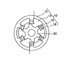
- the dotted line 33 indicates the flow of magnetic lines of force, and it is desirable that the easy magnetization direction of the core material 31 is in the plane of the stacked plate material.
- a single-phase SRM Switchched reluctance motor
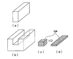
- FIG. 4 has a stator 10 wound with a coil connected to an external power source, and is rotatably installed inside the stator 10.
- the stator 10 and the rotor 20 that rotates by the electromagnetic force acting on each other are constituted.
- the stator 10 includes a plurality of yokes 12 having a ring-type structure, and a plurality of ribs protruding in a radial direction from the yoke 12 toward the rotor 20 and spaced apart from each other via predetermined slots 14 along the circumferential direction. It consists of poles 16 and a coil 18 wound around these poles 16 and connected to an external power source.
- the stator 10 of the motor is obtained by punching out a stator sheet having a planar shape of a yoke 12 and a pole 16 from an extremely thin electromagnetic steel sheet, and stacking the prepared stator sheets at a certain height to form an iron core. It is manufactured by winding a coil 18 around the wire.
- the magnetization of steel has anisotropy due to the crystal axis.
- ⁇ 001> is the most easy to magnetize and has little hysteresis loss
- ⁇ 011> is easy to magnetize and has little hysteresis loss
- ⁇ 111> has a large value. Therefore, it is desirable to preferentially orient ⁇ 001> in the radial direction in the stator or rotor of the motor to facilitate magnetization and reduce iron loss due to hysteresis loss. That is, an iron core material in which ⁇ 001> is oriented rotationally symmetrically about the motor axis is desired.
- the crystal plane ⁇ 100 ⁇ is parallel to the steel plate surface, and ⁇ 001>, which is the crystal easy axis of crystal, is in the plane of the steel plate along the steel plate surface. Therefore, it is desired to develop a non-oriented electrical steel sheet having a high magnetic flux density along the surface of the electrical steel sheet (see, for example, Non-Patent Document 1). .
- a face-centered cubic (FCC) structure metal such as Al
- uniaxial compression processing is effective in realizing a rotationally symmetric crystal orientation around the compression axis.
- Compression surface known for the development of fiber texture.
- a body-centered cubic (BCC) structure metal such as Fe
- ⁇ 111 ⁇ + ⁇ 100 ⁇ double fiber texture that is, ⁇ 111 ⁇ by uniaxial compression processing (cold compression) at room temperature.
- a rotationally symmetric orientation in which ⁇ 100 ⁇ and ⁇ 100 ⁇ are parallel to the compression surface is formed as a crystal orientation that is stable against deformation.
- the conventional uniaxial compression processing for Fe not only allows ⁇ 100 ⁇ to be oriented parallel to the ⁇ 001> steel plate surface having excellent magnetic properties, but also ⁇ 001> cannot be oriented in the plate surface ⁇ 111 ⁇ coexist. Further, in the conventional uniaxial compression process, a state where ⁇ 111 ⁇ is more developed in the plate surface occurs, and therefore, the uniaxial compression process is used as a manufacturing technique of the electrical steel sheet in which ⁇ 001> is oriented in the plate surface. There is no current situation.
- the present invention has an object to control the metal crystal axis in view of the above-described present situation. For example, it is an object to control the easy axis ⁇ 001> of the iron material along the processed surface. And, by controlling the easy magnetization axis ⁇ 001> along the machining surface, a metal material that can be easily magnetized along the plate surface, has a high magnetic flux density and has low magnetic loss, and a manufacturing method thereof are provided. The challenge is to do.
- this change in orientation is due to the fact that when the amount of dislocation increases due to deformation, the ⁇ 100 ⁇ -oriented crystal grains move from the ⁇ 110 ⁇ -oriented crystal grains to other crystal orientations by grain boundary movement. It has been experimentally found that it grows preferentially by consumption and occurs.
- ⁇ 100 ⁇ is a crystal orientation with a small Taylor factor, which is an indicator of the total amount of shear strain in the crystal, which is considered to have a small amount of dislocations introduced along with deformation, and ⁇ 100 ⁇ We focused on being stable and stable.
- This concept is estimated to be applicable to metal materials with a body-centered cubic (BCC) structure in general. Therefore, as a result of a study on an iron-silicon alloy having a body-centered cubic (BCC) structure, that is, silicon steel, as a metal material that makes use of this idea, the coarsening of the crystal grain size and the plate required to increase the magnetic flux density It was discovered that the ⁇ 001> orientation in the plane can be controlled by processing conditions.
- BCC body-centered cubic
- the conventional manufacturing method for non-oriented electrical steel sheets combines the two processes of cold working and heat treatment, or hot working and heat treatment, while hot uniaxial compression or hot working.
- the present invention has been completed by clarifying that an electrical steel sheet in which the easy axis ⁇ 001> is controlled to be along the machined surface can be produced by only one process of plane strain compression.
- the present invention relates to a method for producing a metal material that is a solid solution having a body-centered cubic (BCC) structure, and is crystallized along a processed surface of the metal material by hot compression in a temperature range in which the metal material becomes a BCC single-phase solid solution.
- a method for producing a metal material characterized in that the axis ⁇ 001> is distributed.
- the present invention can distribute the metal crystallographic axis ⁇ 001> along the processing surface without the need for post-processing heat treatment, and the principle is applied to a metal material that is a solid solution of a body-centered cubic (BCC) structure. Therefore, its application range is wide.
- BCC body-centered cubic
- the metal material is an Fe—Si alloy, which is heated to a temperature range where it becomes a BCC single-phase solid solution, the solute atom atmosphere appearing in the BCC single-phase solid solution governs the movement of dislocations, and the crystal grains ⁇ 100 ⁇ is distributed in parallel to the processing surface by compressing the BCC solid solution at a strain rate capable of maintaining a processing state in which the grain boundaries can move using the strain energy accumulated in the driving force as a driving force. It is a manufacturing method of the metal material to perform, for example, an electromagnetic steel plate.
- the solute atomic atmosphere appearing in the BCC single-phase solid solution controls the dislocation movement, and the strain rate that can maintain the processing state in which the grain boundary can move using the strain energy accumulated in the crystal grains as the driving force.
- the solid solution having the body-centered cubic (BCC) structure is an Fe—Si alloy, and the Fe—Si alloy is heated to a temperature range in which it becomes a BCC single-phase solid solution, and the strain rate is 1 ⁇ 10 ⁇ 5. 3.
- the method for producing a metal material for example, a magnetic steel sheet according to claim 1, wherein the metal material is compressed in a range of s ⁇ 1 to 1 ⁇ 10 ⁇ 1 s ⁇ 1 .
- the solute atomic atmosphere appearing in the BCC single-phase solid solution governs the movement of dislocations, and maintains a working state in which the grain boundaries can move using the strain energy accumulated in the grains as the driving force.
- the strain rate that can be produced is in the range of 1 ⁇ 10 ⁇ 5 s ⁇ 1 to 1 ⁇ 10 ⁇ 1 s ⁇ 1.
- ⁇ 100 ⁇ can be distributed parallel to the processing surface.
- an electrical steel sheet made of an Fe—Si alloy having good characteristics can be obtained.
- the Fe—Si alloy is preferably an Fe—Si alloy containing 1 to 7% by weight of Si, with the balance being Fe and inevitable impurities.
- the invention according to claim 4 is characterized in that, in the method for producing the metal material according to claim 3, specifically, the electrical steel sheet, the temperature range is a temperature within a range of 800 to 1300 ° C. .
- the invention according to claim 5 is the method for producing the metal material according to claim 4, specifically, the electrical steel sheet, wherein at least a total amount of the single-phase solid solution having the body-centered cubic (BCC) structure is obtained by the compression processing. Strain amount-It is characterized by giving a strain of 0.5.
- a high-quality electrical steel sheet in which ⁇ 001> is reliably controlled within the plate surface can be obtained by applying at least a total strain of -0.5 by uniaxial compression.
- the crystal orientation with low strain energy is ⁇ 100 ⁇ (compressed surface) in uniaxial compression deformation, and in addition, because this orientation is stable against deformation, grain boundaries move during deformation so that the crystal grains become large. Therefore, if the strain amount is increased, a ⁇ 100 ⁇ fiber texture develops. The larger the strain, the better the result. By increasing the total strain amount, ⁇ 100 ⁇ growth parallel to the machined surface becomes remarkable.
- the present invention is a metal material which is a solid solution having a body-centered cubic (BCC) structure, and is characterized in that the crystal axis ⁇ 001> is distributed along the processed surface by hot compression processing.
- BCC body-centered cubic
- ODF crystal orientation distribution function
- the present invention has realized a high concentration of orientation density in a specific direction that has not been obtained in the past.
- the crystal orientation distribution function (ODF) for examining the distribution of ⁇ 001>
- ODF crystal orientation distribution function
- the electrical steel sheet made of an Fe—Si alloy in which the distribution of ⁇ 001 ⁇ is controlled so as to be parallel to the machined surface is superior in characteristics to conventional non-oriented electrical steel sheets.
- a metal material having a controlled crystal axis is obtained, and particularly for an electromagnetic steel sheet, the easy axis of iron ⁇ 001> is controlled so as to follow the processed surface, and the magnetic flux An electrical steel sheet having high density and low iron loss and excellent magnetic properties is provided.
- One of the phenomena governing the dislocation motion is the drag motion of the solute atomic atmosphere that appears in the solid solution alloy with a combination of temperature and strain rate within a certain range.
- This refers to a state in which dislocations move by being surrounded by solute atoms.
- Si which is a solute atom
- the dislocation is a solute atom atmosphere. Unable to escape from the field, exercise while dragging dislocations. Then, since dislocations drag the solute atomic atmosphere, the movement speed decreases.
- dislocations are distributed uniformly in the crystal, unlike deformation near normal temperature. That is, dislocations that are in a drag motion of the solute atom atmosphere tend to be uniformly distributed in the crystal.
- dislocations are lattice defects and have strain energy. Since the amount of dislocations contributing to deformation differs depending on the crystal orientation, even if the same amount of deformation is given, the amount of dislocation differs for each crystal grain, and as a result, the amount of strain energy accumulated for each crystal grain differs. However, since the dislocations are distributed so as to cancel out the strain field with each other under normal processing conditions, the difference in dislocation density for each crystal grain does not reflect the difference in accumulated strain energy.
- the dislocations are uniformly distributed, so the effect of the dislocations canceling each other's strain is small.
- the difference in the amount of dislocation is directly reflected in the difference in accumulated strain energy.
- the crystal orientation with a low strain energy is ⁇ 100 ⁇ (plate surface) in uniaxial compression deformation of a solid solution having a body-centered cubic (BCC) structure, and ⁇ 100 ⁇ (plate surface) in plane strain compression deformation such as rolling, ⁇ 001 > (Extension direction). Therefore, crystal grains having these crystal orientations grow by consuming crystal grains having other crystal orientations.
- BCC body-centered cubic
- ⁇ 100 ⁇ represents the processed surface and ⁇ 001> represents the stretching direction.
- ⁇ 100 ⁇ is oriented parallel to the plate surface in both uniaxial compression deformation and plane strain compression deformation.
- the crystal plane ⁇ 100 ⁇ is oriented parallel to the plate surface.
- ⁇ 100> which is the normal line of the crystal surface ⁇ 100 ⁇ , is used as the rotation axis with respect to the compression direction in the plate surface.
- the crystal direction ⁇ 001> is uniformly distributed densely in the direction perpendicular to 360 degrees.
- plane strain deformation such as rolling, when the thickness of the plate material is reduced by compression processing, the plate material extends in one direction. In this case, ⁇ 001> is densely distributed in the extending direction.
- the Fe—Si alloy contains an alloy containing at least Si and the balance of Fe and inevitable impurities as a body-centered cubic ( BCC) Heated to a temperature range where a solid solution of the structure is formed, and in this state, the movement of dislocations that causes the solute atom atmosphere generated in the BCC solid solution becomes the dominant deformation mechanism and drives the strain energy accumulated in the crystal grains.
- a plane strain compression process such as uniaxial compression or rolling is performed on the solid solution of the body-centered cubic (BCC) structure at a strain rate capable of maintaining a processing state in which the grain boundary can move as a force. 100 ⁇ is distributed with high density.
- the temperature and strain rate that define the processing conditions are as follows: the temperature range is 800 to 1300 ° C., and the strain rate is 1 ⁇ 10 ⁇ 5 s ⁇ 1 to 1 ⁇ 10 ⁇ 1 s ⁇ 1 . Strain rate.
- the total amount of strain applied to a solid solution having a body-centered cubic (BCC) structure by compression processing is -0.5 or more in terms of true strain.
- the target state develops monotonically as the amount of strain increases, and if the amount of strain is small, it becomes an insufficiently developed state.
- the strain may be applied in multiple steps.
- Si in the solid solution having a body-centered cubic (BCC) structure is added to increase the specific resistance of the steel sheet, reduce the eddy current, and improve the iron loss value due to the eddy current.
- the solid solution having a body-centered cubic (BCC) structure may not be a binary alloy as long as it is a BCC single phase, or may be a ternary or higher system containing components other than Si.
- the Si content is in the composition range of about 1 to 7% by weight. If the Si content is less than 1% by weight, the specific resistance necessary for low iron loss cannot be obtained sufficiently. If the Si content exceeds 7% by weight, cracks increase significantly during compression, and compression processing Therefore, the Si content is desirably 1% by weight at the lower limit and 7% by weight at the upper limit.
- Inevitable impurities in Fe-Si alloys include C, Mn, P, S, Al, N, etc.
- fine sulfide MnS reacts with S and precipitates, resulting in marked deterioration of magnetic properties. It is desirable that Mn to be added and P which inhibits workability be less than 0.01% by weight, and S which inhibits crystal grain growth is less than 0.0001% by weight.
- the temperature for heating it is a temperature in the range of 800 to 1300 ° C. as the temperature range of the BCC single phase.
- the Fe—Si alloy which is always BCC from the low temperature to the melting point when the Si content is in the range of 2 to 5% by weight, also has a high temperature depending on the content when the Si content is less than 2% by weight.
- heating is performed on the lower temperature side in the temperature range of 800 to 1300 ° C. as the temperature range in which the Si content is less than 2% by weight and the temperature range becomes the BCC single phase.
- the strain rate at the time of compression processing of a BCC single-phase solid solution is a so-called processing speed indicating how much strain is given per unit time.
- the mechanism governing the movement of dislocations contributing to deformation changes depending on whether the processing speed is fast or slow. Therefore, the processing speed can maintain the processing conditions in which the solute atomic atmosphere appearing in the BCC solid solution governs the movement of dislocations in the state where the solid solution of the body-centered cubic (BCC) structure is heated to a temperature in the temperature range that becomes the BCC single phase. Limited to the speed you can.
- the strain rate is 1 ⁇ 10 ⁇ 5 s ⁇ 1 to 1 ⁇ 10 ⁇ in combination with a temperature in the temperature range of 800 to 1300 ° C. Set within the range of 1 s -1 .
- This range of strain rate is the range of strain rate from 1 ⁇ 10 ⁇ 5 s ⁇ 1 to 5 ⁇ 10 ⁇ 2 s ⁇ 1 at a temperature of 900 ° C. for an Fe—Si alloy with a Si content of 3% by weight.
- the temperature changes to the low temperature side
- the processing speed for obtaining the same orientation will increase, the single content used in combination with the Si content and temperature within the above range will be used. It is determined as the strain rate applied to the Fe—Si alloy by axial compression.
- Example> The solid solution of the body-centered cubic (BCC) structure that is the material is hot rolled (heating temperature 1100 ° C x 60 minutes, finishing temperature 850 ° C or higher) on a 40 kg ingot produced by vacuum melting. After being cut into a length of 320 mm, a hot rolled product with a finishing thickness of 20 mm (heating temperature 1100 ° C. ⁇ 60 minutes, finishing temperature 850 ° C. or more) was cut to produce a thickness 20 mm, width 140 mm, length It is a columnar steel piece with a circular cross section having a diameter of 12 mm and a height of 18 mm produced from a 290 mm thick plate by an electric discharge machine.
- BCC body-centered cubic
- the ingot was prepared by designating Si as 1.5, 3, 4, 5 wt%, inevitable impurities Mn and P as less than 0.01 wt%, and S as less than 0.001 wt%.
- the four materials A, B, C, and D include, in addition to Mn, P, and S, inevitable impurities other than Mn, P, and S, in terms of weight% C shown in the table. Al, N and the like were contained.
- an electromagnetic steel sheet manufactured from material B having a Si content of 3% by weight processed at a temperature of 900 ° C. and a strain rate of 5.0 ⁇ 10 ⁇ 5 s ⁇ 1 is divided into two so that the height is halved.
- a disk-shaped measurement sample having a diameter of 20 mm ⁇ 3.3 mm was prepared, and the orientation distribution of the crystal was measured by an X-ray diffraction method called a Schulz reflection method after polishing the surface of the cut surface.
- ODF crystal orientation distribution function
- the ⁇ 100 ⁇ pole figure, ⁇ 110 ⁇ pole figure, ⁇ 211 ⁇ pole figure can be drawn with data obtained by different measurements, and the three pole figures can be explained without contradiction by the Schulz reflection method.
- a crystal orientation distribution function (ODF) representing a three-dimensional crystal orientation distribution was calculated by a computer.
- ⁇ 1 , ⁇ , and ⁇ 2 are Euler angles, and the contour lines along the upper and lower sides of the quadrangle represent the distribution of the crystal orientation density in the steel plate surface.
- the numerical values of the contour lines indicate the azimuth density expressed as a multiple of the average value 1, and in the same figure, the contour lines of the numerical values 18, 16, 14, 12, 10, 8, 6, 4 between the numerical values 20 and 1 are shown. Are drawn in this order.
- the crystal orientation distribution of the material before processing is not mentioned, but this means that if the strain amount is increased whatever the state before processing, the processed surface is subjected to hot compression processing. This is because a ⁇ 100 ⁇ fiber texture in which ⁇ 100 ⁇ is oriented parallel to the surface is formed. Of course, you may prepare what has the crystal orientation distribution similar to the existing non-oriented electrical steel sheet.
- the material has a circular cross section, but may be a plate or column having a square shape or a polygonal shape other than a circle.
- the surface to which the uniaxial compression process is applied may be any shape other than the flat surface for the same reason.
- the disk-shaped stator material is used by punching the center portion and the slit. Therefore, the characteristics of the pole 16 part of FIG. 4 are important as the stator material.
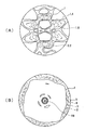
- Fig. 12 shows a model of the BCC structure. Since the BCC structure is symmetrical in the vertical and horizontal directions, [100], [010], and [001] displayed in this figure are equivalent, and the three crystal axes are collectively represented as ⁇ 001>. Further, since all the faces of the cube are equivalent, ⁇ 001 ⁇ , ⁇ 100 ⁇ , and ⁇ 010 ⁇ collectively refer to the same contents.
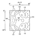
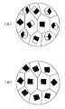
- FIG. 13A shows the state of the easy magnetization direction of a conventional non-oriented electrical steel sheet for a motor stator.
- the easy magnetization direction is three-dimensionally directed in various directions.
- FIG. 13B shows an easy magnetization direction in a substantially ideal electromagnetic steel sheet.
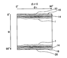
- FIG. 14 shows the distribution of ⁇ 001> in the easy magnetization direction according to the ⁇ 100 ⁇ pole figure.
- FIG. 14A shows a conventional non-oriented electrical steel sheet
- FIG. 14B shows the ⁇ 001> distribution of the electrical steel sheet according to the present invention.
- the numbers in the figure indicate the degree of density concentration of ⁇ 001> with respect to the average value of 1.
- the minimum value of the outer peripheral portion that greatly affects the characteristics is 0.8 times the average value or less.
- the minimum value of the outer peripheral portion is 1.6 times or more of the average value, and the central portion exceeds 19 times of the average value. From this, it can be seen that the ⁇ 001> density of the important outer peripheral portion is significantly higher than the existing material according to the prior art.
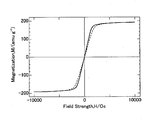
- FIG. 15 shows the magnetic properties of the electrical steel sheet according to the present invention.
- the dotted line in the figure represents the magnetic characteristics of the conventional non-oriented electrical steel sheet, and the solid line represents the magnetic characteristics of the electrical steel sheet according to the present invention.
- a large magnetic flux density is obtained with respect to the applied magnetic field, which can be expected to improve the characteristics of electromagnetic devices such as motors.
- the rolling process shown in FIG. 9 is also possible.
- ⁇ 100 ⁇ develops parallel to the rolling surface, and ⁇ 001> is distributed in the rolling direction in a large amount.
- a plate material can be obtained.
- ⁇ 001> can be distributed in multiple directions in the plane, and the same effect as the uniaxial compression process can be obtained.
- the strain amount can be increased to obtain a thinner magnetic steel sheet, and the magnetic properties of the magnetic steel sheet thus obtained will be more excellent. Since this processing is performed at a high temperature, the amount of lattice defects remaining after processing is small, but by performing annealing for a short time after processing, it is possible to obtain a non-oriented electrical steel sheet in which the amount of lattice defects is further reduced. .
- Fe—Si which is an electromagnetic material
- BCC body-centered cubic
- a manufacturing method of a metal material for example, an electromagnetic material, whose crystal axis orientation is controlled is clarified, and electromagnetic loss is reduced by providing a good electromagnetic material, thereby reducing the cost of society as a whole. In addition to contributing to environmental problems.
Abstract
Description
材料となる体心立方(BCC)構造の固溶体は、真空溶解して作製した40kgのインゴットに仕上げ厚40mmの熱間圧延(加熱温度1100℃×60分、仕上げ温度850℃以上)を行い、これを長さ320mmに切断した後、さらに仕上げ厚20mmの熱間圧延(加熱温度1100℃×60分、仕上げ温度850℃以上)を行ったものを切断して作製した厚さ20mm、幅140mm、長さ290mmの板から放電加工機により作製した直径12mm、高さ18mmの大きさの断面円形の柱状の鋼片である。 <Example>
The solid solution of the body-centered cubic (BCC) structure that is the material is hot rolled (heating temperature 1100 ° C x 60 minutes, finishing temperature 850 ° C or higher) on a 40 kg ingot produced by vacuum melting. After being cut into a length of 320 mm, a hot rolled product with a finishing thickness of 20 mm (heating temperature 1100 ° C. × 60 minutes, finishing temperature 850 ° C. or more) was cut to produce a

12 ヨーク
14 スロット
16 ポール
18 コイル
20 モータのロータ
31 コア
32 コイル
33 磁力線 10
Claims (8)
- 体心立方(BCC)構造の固溶体である金属材料の製造方法であって単相固溶体となる温度域での熱間圧縮加工により前記金属材料の加工面に沿って前記金属材料の結晶軸<001>を分布させたことを特徴とする金属材料の製造方法。 A manufacturing method of a metal material which is a solid solution having a body-centered cubic (BCC) structure, and a crystal axis <001 of the metal material along a processing surface of the metal material by hot compression processing in a temperature range where a single-phase solid solution is formed > Is distributed. The manufacturing method of the metal material characterized by the above-mentioned.
- 前記金属材料がFe-Si合金でありこれを体心立方(BCC)構造の単相固溶体となる温度域に加熱し、体心立方(BCC)構造の単相固溶体に現れる溶質原子雰囲気が転位の運動を支配し、かつ結晶粒に蓄積されているひずみエネルギーを駆動力として結晶粒界が移動できる加工状態を維持できるひずみ速度で前記体心立方(BCC)構造の固溶体に熱間圧縮加工を行うことで加工面と平行に{100}を分布させたことを特徴とする金属材料の製造方法。 The metal material is an Fe—Si alloy, which is heated to a temperature range that becomes a single-phase solid solution having a body-centered cubic (BCC) structure, and a solute atomic atmosphere appearing in the single-phase solid solution having a body-centered cubic (BCC) structure Hot compression processing is performed on the solid solution of the body-centered cubic (BCC) structure at a strain rate capable of maintaining the processing state in which the grain boundary can move using the strain energy accumulated in the crystal grains as a driving force. Thus, {100} is distributed in parallel to the processed surface.
- 前記体心立方(BCC)構造の固溶体がFe-Si合金であり、前記Fe-Si合金が単相固溶体となる温度域に加熱され、ひずみ速度が1×10⁻⁵s-1から1×10⁻¹s-1の範囲内で熱間圧縮加工されたことを特徴とする請求項1または2に記載の金属材料の製造方法。 The solid solution having the body-centered cubic (BCC) structure is an Fe—Si alloy, heated to a temperature range in which the Fe—Si alloy becomes a single-phase solid solution, and a strain rate of 1 × 10 −5 s −1 to 1 × 10 The method for producing a metal material according to claim 1, wherein the metal material is hot-compressed within a range of −1 s −1 .
- 前記温度域が800~1300°Cの範囲内の温度であることを特徴とする請求項3に記載の金属材料の製造方法。 The method for producing a metal material according to claim 3, wherein the temperature range is a temperature within a range of 800 to 1300 ° C.
- 前記熱間圧縮加工により前記の体心立方(BCC)構造の単相固溶体に、少なくとも総ひずみ量―0.5のひずみを与えることを特徴とする請求項4に記載の金属材料の製造方法。 5. The method for producing a metal material according to claim 4, wherein a strain of at least a total strain amount of -0.5 is applied to the single-phase solid solution having the body-centered cubic (BCC) structure by the hot compression processing.
- 体心立方(BCC)構造の固溶体である金属材料であって熱間圧縮加工により加工面に沿って結晶軸<001>が分布したことを特徴とする金属材料。 A metal material, which is a solid solution having a body-centered cubic (BCC) structure, wherein the crystal axis <001> is distributed along the processed surface by hot compression processing.
- 前記金属材料の加工面に沿う金属の結晶軸<001>の分布を表す結晶方位分布関数(ODF)のφ2=0°断面のΦ=0°線上の方位密度が平均値1に対して14倍以上であることを特徴とする請求項6に記載の金属材料。 The orientation density on the Φ = 0 ° line of the φ 2 = 0 ° section of the crystal orientation distribution function (ODF) representing the distribution of the crystal axis <001> of the metal along the processed surface of the metal material is 14 with respect to the average value 1 The metal material according to claim 6, wherein the metal material is twice or more.
- 前記体心立方(BCC)構造の固溶体がFe-Si合金であることを特徴とする請求項6または請求項7に記載の金属材料。 The metal material according to claim 6 or 7, wherein the solid solution having a body-centered cubic (BCC) structure is an Fe-Si alloy.
Priority Applications (5)
| Application Number | Priority Date | Filing Date | Title |
|---|---|---|---|
| EP11747563.2A EP2540845A4 (en) | 2010-02-26 | 2011-02-28 | Metallic material which is solid solution of body-centered cubic (bcc) structure having controlled crystal axis<001>orientation, and process for producing same |
| US13/580,722 US20120312432A1 (en) | 2010-02-26 | 2011-02-28 | Metallic material as a solid solution having a body-centered cubic (bcc) structure, an orientation of crystal axis <001> of which is controlled, and method of manufacturing the same |
| CN201180016355.4A CN102869795B (en) | 2010-02-26 | 2011-02-28 | Metallic material which is solid solution of body-centered cubic (bcc) structure having controlled crystal axis <001> orientation, and process for producing same |
| JP2012501909A JP5492975B2 (en) | 2010-02-26 | 2011-02-28 | Metal material which is a solid solution having a body-centered cubic (BCC) structure in which the orientation of crystal axis <001> is controlled, and a method for producing the same |
| KR1020127024629A KR101433493B1 (en) | 2010-02-26 | 2011-02-28 | Metallic material which is solid solution of body-centered cubic(bcc) structure having controlled crystal axis 〈001〉 orientation, and process for producing same |
Applications Claiming Priority (2)
| Application Number | Priority Date | Filing Date | Title |
|---|---|---|---|
| JP2010-042132 | 2010-02-26 | ||
| JP2010042132 | 2010-02-26 |
Publications (1)
| Publication Number | Publication Date |
|---|---|
| WO2011105609A1 true WO2011105609A1 (en) | 2011-09-01 |
Family
ID=44507002
Family Applications (1)
| Application Number | Title | Priority Date | Filing Date |
|---|---|---|---|
| PCT/JP2011/054548 WO2011105609A1 (en) | 2010-02-26 | 2011-02-28 | Metallic material which is solid solution of body-centered cubic (bcc) structure having controlled crystal axis <001> orientation, and process for producing same |
Country Status (6)
| Country | Link |
|---|---|
| US (1) | US20120312432A1 (en) |
| EP (1) | EP2540845A4 (en) |
| JP (1) | JP5492975B2 (en) |
| KR (1) | KR101433493B1 (en) |
| CN (1) | CN102869795B (en) |
| WO (1) | WO2011105609A1 (en) |
Cited By (4)
| Publication number | Priority date | Publication date | Assignee | Title |
|---|---|---|---|---|
| JP2016153521A (en) * | 2015-02-20 | 2016-08-25 | 公立大学法人兵庫県立大学 | Iron plate and manufacturing method therefor |
| JP2018092979A (en) * | 2016-11-30 | 2018-06-14 | 新日鐵住金株式会社 | Transformer, plate-shaped iron core for transformer, and method for manufacturing plate-shaped iron core for transformer |
| WO2023112891A1 (en) * | 2021-12-16 | 2023-06-22 | Jfeスチール株式会社 | Non-oriented electromagnetic steel sheet and method for manufacturing same |
| WO2023112892A1 (en) * | 2021-12-16 | 2023-06-22 | Jfeスチール株式会社 | Non-oriented electromagnetic steel sheet and method for manufacturing same |
Families Citing this family (3)
| Publication number | Priority date | Publication date | Assignee | Title |
|---|---|---|---|---|
| US10594172B2 (en) * | 2015-11-12 | 2020-03-17 | Hamilton Sundstrand Corporation | Electric component including custom metal grain orientation |
| KR101940968B1 (en) * | 2015-12-11 | 2019-01-21 | 신닛테츠스미킨 카부시키카이샤 | METHOD FOR MANUFACTURING MOLDED PRODUCTS |
| KR102407998B1 (en) * | 2018-02-16 | 2022-06-14 | 닛폰세이테츠 가부시키가이샤 | Non-oriented electrical steel sheet and manufacturing method of non-oriented electrical steel sheet |
Citations (3)
| Publication number | Priority date | Publication date | Assignee | Title |
|---|---|---|---|---|
| JPH10226854A (en) * | 1997-02-19 | 1998-08-25 | Kawasaki Steel Corp | Silicon steel hot rolled sheet excellent in magnetic property and its production |
| JP2000104144A (en) * | 1998-07-29 | 2000-04-11 | Kawasaki Steel Corp | Silicon steel sheet excellent in magnetic property in l orientation and c orientation and its production |
| JP2006087289A (en) | 2004-09-15 | 2006-03-30 | Lg Electronics Inc | Stator of motor and manufacturing method therefor |
Family Cites Families (7)
| Publication number | Priority date | Publication date | Assignee | Title |
|---|---|---|---|---|
| JP2708682B2 (en) * | 1991-12-27 | 1998-02-04 | 新日本製鐵株式会社 | Non-oriented electrical steel sheet having extremely excellent magnetic properties and method for producing the same |
| TW476790B (en) * | 1998-05-18 | 2002-02-21 | Kawasaki Steel Co | Electrical sheet of excellent magnetic characteristics and its manufacturing method |
| JP4123629B2 (en) * | 1999-04-23 | 2008-07-23 | Jfeスチール株式会社 | Electrical steel sheet and manufacturing method thereof |
| JP4972767B2 (en) * | 2006-08-25 | 2012-07-11 | Jfeスチール株式会社 | Method for producing high silicon steel sheet |
| KR100797895B1 (en) * | 2006-12-22 | 2008-01-24 | 성진경 | Method of forming cube-on-face texture on surface, method of manufacturing non-oriented electrical steel sheets using the same and non-oriented electrical steel sheets manufactured by using the same |
| CN101417292B (en) * | 2008-12-16 | 2011-05-11 | 攀钢集团钢铁钒钛股份有限公司 | Method for controlling middle, low grade electric steel rolling using conventional rolling model |
| KR101110253B1 (en) * | 2008-12-26 | 2012-03-13 | 주식회사 포스코 | Non-oriented magnetic steel sheet with superior workability and manufacturing method thereof |
-
2011
- 2011-02-28 CN CN201180016355.4A patent/CN102869795B/en not_active Expired - Fee Related
- 2011-02-28 JP JP2012501909A patent/JP5492975B2/en active Active
- 2011-02-28 US US13/580,722 patent/US20120312432A1/en not_active Abandoned
- 2011-02-28 WO PCT/JP2011/054548 patent/WO2011105609A1/en active Application Filing
- 2011-02-28 KR KR1020127024629A patent/KR101433493B1/en not_active IP Right Cessation
- 2011-02-28 EP EP11747563.2A patent/EP2540845A4/en not_active Withdrawn
Patent Citations (3)
| Publication number | Priority date | Publication date | Assignee | Title |
|---|---|---|---|---|
| JPH10226854A (en) * | 1997-02-19 | 1998-08-25 | Kawasaki Steel Corp | Silicon steel hot rolled sheet excellent in magnetic property and its production |
| JP2000104144A (en) * | 1998-07-29 | 2000-04-11 | Kawasaki Steel Corp | Silicon steel sheet excellent in magnetic property in l orientation and c orientation and its production |
| JP2006087289A (en) | 2004-09-15 | 2006-03-30 | Lg Electronics Inc | Stator of motor and manufacturing method therefor |
Non-Patent Citations (2)
| Title |
|---|
| NIPPON STEEL MONTHLY, April 2005 (2005-04-01), pages 11 - 14 |
| See also references of EP2540845A4 * |
Cited By (6)
| Publication number | Priority date | Publication date | Assignee | Title |
|---|---|---|---|---|
| JP2016153521A (en) * | 2015-02-20 | 2016-08-25 | 公立大学法人兵庫県立大学 | Iron plate and manufacturing method therefor |
| JP2018092979A (en) * | 2016-11-30 | 2018-06-14 | 新日鐵住金株式会社 | Transformer, plate-shaped iron core for transformer, and method for manufacturing plate-shaped iron core for transformer |
| WO2023112891A1 (en) * | 2021-12-16 | 2023-06-22 | Jfeスチール株式会社 | Non-oriented electromagnetic steel sheet and method for manufacturing same |
| WO2023112892A1 (en) * | 2021-12-16 | 2023-06-22 | Jfeスチール株式会社 | Non-oriented electromagnetic steel sheet and method for manufacturing same |
| JP7371815B1 (en) | 2021-12-16 | 2023-10-31 | Jfeスチール株式会社 | Non-oriented electrical steel sheet and its manufacturing method |
| JP7439993B2 (en) | 2021-12-16 | 2024-02-28 | Jfeスチール株式会社 | Non-oriented electrical steel sheet and its manufacturing method |
Also Published As
| Publication number | Publication date |
|---|---|
| CN102869795B (en) | 2015-07-08 |
| EP2540845A1 (en) | 2013-01-02 |
| KR20120127652A (en) | 2012-11-22 |
| EP2540845A4 (en) | 2016-03-09 |
| US20120312432A1 (en) | 2012-12-13 |
| KR101433493B1 (en) | 2014-08-22 |
| JP5492975B2 (en) | 2014-05-14 |
| JPWO2011105609A1 (en) | 2013-06-20 |
| CN102869795A (en) | 2013-01-09 |
Similar Documents
| Publication | Publication Date | Title |
|---|---|---|
| JP5492975B2 (en) | Metal material which is a solid solution having a body-centered cubic (BCC) structure in which the orientation of crystal axis <001> is controlled, and a method for producing the same | |
| JP4855222B2 (en) | Non-oriented electrical steel sheet for split core | |
| JP5375559B2 (en) | Non-oriented electrical steel sheet shearing method and electromagnetic component manufactured using the method | |
| CA2928605C (en) | Ultra-low cobalt iron-cobalt magnetic alloys | |
| JP2017040002A (en) | Nonoriented electrical steel sheet for high frequency and method for producing the same | |
| JP6828815B2 (en) | Non-oriented electrical steel sheet | |
| JP6604120B2 (en) | Non-oriented electrical steel sheet and manufacturing method thereof | |
| JP2535963B2 (en) | Silicon steel sheet having excellent magnetic properties and method for producing the same | |
| JP6828816B2 (en) | Non-oriented electrical steel sheet | |
| JP6623533B2 (en) | Fe-based metal plate | |
| JPH0674460B2 (en) | Magnetic steel sheet manufacturing method | |
| JP4790537B2 (en) | Method for producing non-oriented electrical steel sheet with all-around characteristics and good workability | |
| JP2008260996A (en) | Non-oriented electromagnetic steel sheet superior in magnetic properties in rolling direction, and manufacturing method therefor | |
| JP4855221B2 (en) | Non-oriented electrical steel sheet for split core | |
| KR20210083203A (en) | Soft magnetic alloy, soft magnetic alloy ribbon, method of manufacturing soft magnetic alloy ribbon, magnetic core, and component | |
| JP2011184787A (en) | High tensile strength non-oriented electromagnetic steel sheet having excellent high frequency iron loss | |
| TWI750894B (en) | Rotor core, rotor and rotating electric machine | |
| JP6221406B2 (en) | Fe-based metal plate and manufacturing method thereof | |
| JP7415137B2 (en) | Laminated core and rotating electrical machinery | |
| JP7343770B2 (en) | Laminated core and rotating electrical machinery | |
| Kustas | Shear-based deformation processing and characterization of electrical steel sheet | |
| JP6537131B2 (en) | Iron plate and method of manufacturing the same | |
| WO2021095861A1 (en) | Stator core, rotary electric machine, and design method for stator core | |
| JP2014237879A (en) | Method of producing solid-solution alloy, solid-solution alloy, electrical steel sheet and electrical bar steel | |
| JP6685491B2 (en) | Non-oriented electrical steel sheet for motor and manufacturing method thereof |
Legal Events
| Date | Code | Title | Description |
|---|---|---|---|
| WWE | Wipo information: entry into national phase |
Ref document number: 201180016355.4 Country of ref document: CN |
|
| 121 | Ep: the epo has been informed by wipo that ep was designated in this application |
Ref document number: 11747563 Country of ref document: EP Kind code of ref document: A1 |
|
| WWE | Wipo information: entry into national phase |
Ref document number: 13580722 Country of ref document: US Ref document number: 2347/KOLNP/2012 Country of ref document: IN |
|
| WWE | Wipo information: entry into national phase |
Ref document number: 2012501909 Country of ref document: JP |
|
| NENP | Non-entry into the national phase |
Ref country code: DE |
|
| ENP | Entry into the national phase |
Ref document number: 20127024629 Country of ref document: KR Kind code of ref document: A |
|
| REEP | Request for entry into the european phase |
Ref document number: 2011747563 Country of ref document: EP |
|
| WWE | Wipo information: entry into national phase |
Ref document number: 2011747563 Country of ref document: EP |