WO2011105214A1 - レンズ駆動装置 - Google Patents
レンズ駆動装置 Download PDFInfo
- Publication number
- WO2011105214A1 WO2011105214A1 PCT/JP2011/052733 JP2011052733W WO2011105214A1 WO 2011105214 A1 WO2011105214 A1 WO 2011105214A1 JP 2011052733 W JP2011052733 W JP 2011052733W WO 2011105214 A1 WO2011105214 A1 WO 2011105214A1
- Authority
- WO
- WIPO (PCT)
- Prior art keywords
- lens
- shape memory
- memory alloy
- lens holder
- optical axis
- Prior art date
- Legal status (The legal status is an assumption and is not a legal conclusion. Google has not performed a legal analysis and makes no representation as to the accuracy of the status listed.)
- Ceased
Links
Images









Classifications
-
- G—PHYSICS
- G02—OPTICS
- G02B—OPTICAL ELEMENTS, SYSTEMS OR APPARATUS
- G02B7/00—Mountings, adjusting means, or light-tight connections, for optical elements
- G02B7/02—Mountings, adjusting means, or light-tight connections, for optical elements for lenses
- G02B7/04—Mountings, adjusting means, or light-tight connections, for optical elements for lenses with mechanism for focusing or varying magnification
- G02B7/10—Mountings, adjusting means, or light-tight connections, for optical elements for lenses with mechanism for focusing or varying magnification by relative axial movement of several lenses, e.g. of varifocal objective lens
- G02B7/102—Mountings, adjusting means, or light-tight connections, for optical elements for lenses with mechanism for focusing or varying magnification by relative axial movement of several lenses, e.g. of varifocal objective lens controlled by a microcomputer
-
- F—MECHANICAL ENGINEERING; LIGHTING; HEATING; WEAPONS; BLASTING
- F03—MACHINES OR ENGINES FOR LIQUIDS; WIND, SPRING, OR WEIGHT MOTORS; PRODUCING MECHANICAL POWER OR A REACTIVE PROPULSIVE THRUST, NOT OTHERWISE PROVIDED FOR
- F03G—SPRING, WEIGHT, INERTIA OR LIKE MOTORS; MECHANICAL-POWER PRODUCING DEVICES OR MECHANISMS, NOT OTHERWISE PROVIDED FOR OR USING ENERGY SOURCES NOT OTHERWISE PROVIDED FOR
- F03G7/00—Mechanical-power-producing mechanisms, not otherwise provided for or using energy sources not otherwise provided for
- F03G7/06—Mechanical-power-producing mechanisms, not otherwise provided for or using energy sources not otherwise provided for using expansion or contraction of bodies due to heating, cooling, moistening, drying or the like
- F03G7/061—Mechanical-power-producing mechanisms, not otherwise provided for or using energy sources not otherwise provided for using expansion or contraction of bodies due to heating, cooling, moistening, drying or the like characterised by the actuating element
- F03G7/0614—Mechanical-power-producing mechanisms, not otherwise provided for or using energy sources not otherwise provided for using expansion or contraction of bodies due to heating, cooling, moistening, drying or the like characterised by the actuating element using shape memory elements
- F03G7/06143—Wires
Definitions
- the present invention relates to a lens driving device, and more particularly to a lens driving device using a shape memory alloy as an actuator.
- a drive device linear actuator using a shape memory alloy (SMA) is known.
- SMA shape memory alloy
- Patent Document 1 discloses a “camera lens driving device” that drives the movement of one camera lens supported by one support structure (housing) by one suspension system.
- the camera lens driving device disclosed in Patent Document 1 incorporates a subassembly having an SMA wire connected to at least one attachment member attached to a support structure. At least two SMA wires are held with tension between the camera lens element and the support structure (housing), each at an acute angle with respect to the optical axis to which tension is applied having a component along the optical axis. The two SMA wires are held at an angle when viewed along the optical axis.
- the subassembly has a mounting member in which SMA wires are connected by caulking.
- the attachment member is electrically connected to the SMA wire. Therefore, the attachment member serves as an electrode.
- the attachment member (electrode) is attached to a recess formed in the support structure (annular wall).
- Patent Document 2 discloses a “lens driving device” that improves transmission efficiency and is compact.
- the lens driving device disclosed in Patent Document 2 includes a fixed barrel (housing), a lens frame (lens holder) that holds a part or all of a lens group (lens barrel) constituting an optical system, and a fixed mirror.
- the lens driving device moves the lens frame toward the other side against the bias of the biasing means with respect to the fixed barrel.
- the lens driving device disclosed in Patent Document 2 includes a shape memory alloy (SMA) wire and a wire bearing member. Both ends of the SMA wire are fixed to the fixed lens barrel, and when heated by energization, the SMA wire is contracted from a predetermined length of a relaxed state.
- SMA shape memory alloy
- both ends of the SMA wire are fixed to a pair of wire support members, and the pair of wire support members are fixed to a fixed lens barrel (housing).
- the energization control unit energizes both ends of the SMA wire via the pair of wire support members. Therefore, the wire support member acts as an electrode.
- Patent Document 3 discloses a “drive module” that can reduce the variation in assembly accuracy while improving the manufacturing efficiency.
- the drive module disclosed in Patent Document 3 is a shape memory alloy (SMA) wire in which a driven body (lens holder) movably provided on a chassis (housing; support body) expands and contracts in accordance with the amount of energization. It is locked to the middle part.
- the drive module includes a pair of holding terminals, and the chassis (housing; support) includes a positioning portion and a locking portion.
- Patent Document 4 discloses a “driving module” that reduces the possibility of breakage or failure due to impact force due to dropping or the like and can be downsized. Yes.
- the drive module disclosed in Patent Document 4 includes a lens frame, a module frame housed inside the lens frame, an upper leaf spring, and the lens frame against a biasing force of the upper leaf spring in a certain direction. And an SMA wire that is driven along.
- a guide protrusion is provided on the outer side in the radial direction of the lens frame so as to protrude outward in the radial direction.
- a notch is formed at the bottom of one corner of the module frame.
- the groove width in plan view of the notch has such a size as to be fitted to the guide projection of the lens frame so as to be movable in the axial direction.
- a pair of locking grooves are provided at two corners adjacent to the cutout of the module frame.
- the pair of locking grooves are for attaching a pair of wire holding members for holding the SMA wire on the side surface on the same direction side as the corner where the notch is provided.
- the SMA wire whose both ends are held by the pair of wire holding members is locked from below to the tip key portion of the guide protrusion of the lens frame protruding from the notch of the module frame.
- Patent Document 5 discloses a “lens driving device” that can move a lens smoothly and quickly and is miniaturized so that it can be incorporated into a portable information terminal. ing.
- the lens driving device disclosed in Patent Document 5 includes a front coil spring and a rear coil spring that are arranged in contact with each other to urge the lens frame from the front side and the rear side in the optical axis direction. At least one of the front coil spring and the rear coil spring is made of a shape memory alloy.
- both the front coil spring and the rear coil spring may be made of a shape memory alloy.
- both the front side coil spring and the rear side coil spring are made of shape memory alloy, when one is energized and heated, the other is energized and overheated, and it should be configured to contract. Yes. That is, both the front coil spring and the rear coil spring act as drive springs.
- Patent Documents 1 to 4 have problems as described below.
- one SMA wire is disposed only on one side of the fixed barrel. Therefore, the length of the SMA wire cannot be increased, and it is difficult to ensure a sufficient amount of lens displacement.
- one shape memory alloy (SMA) wire is disposed only on one side of the driven body (lens holder). Therefore, the length of the SMA wire cannot be increased, and it is difficult to ensure a sufficient amount of lens displacement.
- one SMA wire is disposed on two side surfaces of the module frame. Therefore, the length of the SMA wire cannot be increased, and it is difficult to ensure a sufficient amount of lens displacement.
- Patent Documents 1 to 4 use a shape memory alloy wire formed in a linear shape as a shape memory alloy member. As a result, there is a limit to the amount of lens displacement of the lens driving device. In other words, the lens displacement amount of the lens driving device depends on the displacement amount of the shape memory alloy wire.
- Patent Document 5 merely discloses that both the front coil spring and the rear coil spring may be used as drive springs.
- an object of the present invention is to provide a lens driving device capable of ensuring a sufficient amount of lens displacement.
- a lens driving device includes a lens holder including a cylindrical portion that holds a lens barrel, a housing that supports the lens holder so as to be movable only in the optical axis direction, A moving means for moving the lens holder in the optical axis direction; and a guiding means for guiding the lens holder so as to be movable only in the optical axis direction.
- the moving means is one shape memory alloy that extends substantially around the outer periphery of the lens holder and is stretched between the lens holder and the housing. Includes members.
- the lens holder is arranged to protrude radially outward from the cylindrical portion at an equal angular interval of (360 ° / N) (N is an integer of 2 or more) with the optical axis as the center, and one shape memory alloy member is attached to the lens holder. Includes N holder hooks to be hooked.
- one shape memory alloy member which is a moving means extends so as to substantially make one round of the outer periphery of the lens holder, the length of the shape memory alloy wire can be increased, A sufficient amount of lens displacement can be ensured.
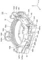
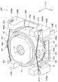
- FIG. 9 is a cross-sectional view taken along line IX-IX in FIG. 8. It is the disassembled perspective view which looked at the external appearance of the lens drive device by the 3rd Embodiment of this invention from diagonally forward upper direction. It is the perspective view which looked at the external appearance of the lens drive device by the 4th Embodiment of this invention from diagonally forward upper direction. It is the perspective view which looked at the lens drive device shown in FIG. 11 from diagonally forward upper direction in the state which excluded the outer side upper cover.
- FIG. 11 It is the disassembled perspective view which looked at the lens drive device shown in FIG. 11 from diagonally forward upper direction. It is the perspective view which looked at the state where the SMA assembly used for the lens drive device shown in FIG. It is the perspective view which looked at the state shown in FIG. 14 from the left rear upper direction. It is the perspective view which looked at the external appearance of the lens drive device by the 5th Embodiment of this invention from diagonally forward upper direction. It is the disassembled perspective view which looked at the lens drive device shown in FIG. 16 from diagonally forward upper direction. It is the perspective view which looked at the lens drive device shown in FIG. 16 from diagonally forward upper direction, omitting an outer upper cover and an upper leaf spring.
- FIG. 19 is a perspective view of the lens driving device shown in FIG. 18 as viewed from diagonally forward above, omitting the actuator base and the lower leaf spring.
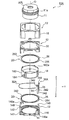
- FIG. 1 is an exploded perspective view of the lens driving device 10 as viewed obliquely from above and front.
- an orthogonal coordinate system (X, Y, Z) is used.
- the X-axis direction is the front-rear direction (depth direction)
- the Y-axis direction is the left-right direction (width direction)
- the Z-axis direction is The vertical direction (height direction).
- the vertical direction Z is the direction of the optical axis O of the lens.
- the optical axis O direction that is, the Z-axis direction is the front-rear direction.
- the upward direction of the Z axis is the forward direction
- the downward direction of the Z axis is the backward direction.
- the illustrated lens driving device 10 passes on a plane that passes perpendicularly to the optical axis O and that is defined by (extends to) the first diagonal direction passing through the up-down direction Z and the front right and back left. On the other hand, it has a substantially plane-symmetric structure.
- the illustrated lens driving device 10 is provided in, for example, a camera-equipped mobile phone capable of autofocusing.
- the lens driving device 10 includes a lens barrel (lens assembly) 11 that incorporates an autofocus lens AFL that is a movable lens.
- the lens driving device 10 is for moving the lens barrel 11 only in the optical axis O direction.
- the lens driving device 10 includes a substantially rectangular parallelepiped housing (housing) 12 that covers the lens barrel 11.
- the lens barrel 11 is arranged in the housing (housing) 12.
- the housing (housing) 12 includes an actuator base 14 and an outer upper cover 16.
- the housing 12 has four corners. Here, of these four corners, the right front corner is called a first corner, and the left rear corner is called a second corner.
- an image sensor arranged on the substrate is mounted in the center of the actuator base 14.
- This imaging device captures a subject image formed by the movable lens AFL and converts it into an electrical signal.
- the image pickup device is configured by, for example, a charge coupled device (CCD) image sensor, a complementary metal oxide (CMOS) image sensor, or the like.
- the lens driving device 10 includes a lens holder 18 that holds the lens barrel 11.
- the lens barrel 11 is held and fixed in the lens holder 18.
- the lens holder 18 includes a cylindrical portion 182 having a substantially cylindrical shape.
- a female screw 182 a is cut on the inner peripheral wall of the cylindrical portion 182 of the lens holder 18.
- a male screw 11 a that is screwed into the female screw is cut on the outer peripheral wall of the lens barrel 11. Therefore, in order to attach the lens barrel 11 to the lens holder 18, the lens barrel 11 is rotated around the optical axis O with respect to the lens holder 18 and screwed along the optical axis O direction. It is accommodated in the lens holder 18 and joined together by an adhesive or the like.
- the lens holder 18 is supported in the housing 12 so as to be movable only in the direction of the optical axis O, as will be described later.
- the lens movable portion (11, 18) is configured by a combination of the lens barrel 11 and the lens holder 18.
- the cylindrical wall 182 of the lens holder 18 passes through the outer peripheral wall orthogonal to the optical axis O and intersects (orthogonal) with the first diagonal direction (that is, passes through the left front and the right rear). ) It has two holder hook portions 184 (in FIG. 1, only one holder hook portion on the left front is shown) protruding radially outward in the second diagonal direction. These two holder hook portions 184 are for hooking one shape memory alloy wire 32 formed in a linear shape to be described later.
- the pair of projecting portions (holder / hook portions) 184 are arranged in a radial direction from the cylindrical portion 182 at equal angular intervals of 180 ° about the optical axis O (facing in the second diagonal direction). It is arranged to protrude outward.
- the actuator base 14 includes a ring-shaped base portion 142 and first to fourth base protruding portions 146, 147, 148, and 149 that protrude upward in the vertical direction Z at the four corners of the base portion 142.
- the first base protrusion 146 is provided at the right front corner
- the second base protrusion 147 is provided at the left front corner
- the third base protrusion 148 is provided at the left rear corner
- the fourth base is provided at the right rear corner. Accordingly, the first base protruding portion 146 and the third base protruding portion 148 are arranged on the opposite side (opposite) on the first diagonal line with the optical axis O in between.
- the first base protruding portion 146 includes an electrode holding portion 146a for holding a pair of electrodes 34 to be described later.
- the third base protrusion 148 includes a housing hook 148a for hooking the one shape memory alloy wire 32.
- the electrode holding portion 146 a is formed at the first corner of the housing 12, and the housing hook portion 148 a is formed at the second corner of the housing 12.
- the lens driving device 10 includes an upper leaf spring 26 and a lower leaf spring 28 provided on the upper and lower sides of the cylindrical portion 182 of the lens holder 18 in the optical axis O direction.
- the upper leaf spring 26 and the lower leaf spring 28 are disposed between the lens holder 18 and the housing 12 and support the elastic member 20 so as to be displaceable in the optical axis O direction with the lens holder 18 positioned in the radial direction. Work as.
- the upward direction in the Z-axis direction (optical axis O direction) is the forward direction
- the downward direction in the Z-axis direction (optical axis O direction) is the backward direction. Therefore, the upper leaf spring 26 is also referred to as a front spring
- the lower leaf spring 28 is also referred to as a rear spring.
- the upper leaf spring 26 is disposed on the upper side of the lens holder 18 in the optical axis O direction
- the lower leaf spring 28 is disposed on the lower side of the lens holder 18 in the optical axis O direction.
- the upper leaf spring 26 and the lower leaf spring 28 have substantially the same configuration.
- the upper leaf spring 26 has an inner peripheral end 262 attached to the lens holder 18 and an outer peripheral end 264 attached to the housing 12 as will be described later.
- a plurality of arm portions (not shown) provided along the circumferential direction are provided between the inner peripheral side end portion 262 and the outer peripheral side portion 264 in order to connect them.
- the inner peripheral end 262 has an annular shape.
- the outer peripheral end 264 is provided apart from the inner peripheral end 262 and has an octagonal ring shape larger than the inner peripheral end 262. Each arm portion extends along the circumferential direction.
- the inner peripheral side end 262 of the upper leaf spring 26 is fixed to the upper end of the cylindrical portion 182 of the lens holder 18.
- the outer peripheral side end 264 of the upper leaf spring 26 is fixed to the housing 12 as described later.
- the housing 12 further includes a resin inner upper cover 30 provided inside the outer upper cover 16. The inner upper cover 30 fixes the outer peripheral end 264 of the upper leaf spring 26.
- the housing 12 includes the actuator base 14, the outer upper cover 16, and the inner upper cover 30.
- the lower leaf spring 28 has an inner peripheral end 282 attached to the lens holder 18 and an outer peripheral end 284 attached to the housing 12 as will be described later.
- a plurality of arm portions (not shown) provided along the circumferential direction are provided between the inner peripheral side end portion 282 and the outer peripheral side portion 284 in order to connect them.
- the inner peripheral side end 282 has an annular shape.
- the outer peripheral end 284 is provided apart from the inner peripheral end 282 and has an octagonal ring shape larger than the inner peripheral end 282. Each arm portion extends along the circumferential direction.
- the inner peripheral side end 282 of the lower leaf spring 28 is fixed to the lower end side of the cylindrical portion 182 of the lens holder 18 by the adhesive force of the resin.
- the outer peripheral side end portion 284 of the lower leaf spring 28 is fixed to the base portion 142 of the actuator base 14 of the housing 12.
- inner peripheral side end portions 262 and 282 are also called inner rings
- outer peripheral side end portions 264 and 284 are also called outer rings.
- the elastic member 20 composed of the upper leaf spring 26 and the lower leaf spring 28 serves as a guide means for guiding the lens holder 18 so as to be movable only in the direction of the optical axis O.
- Each of the upper leaf spring 26 and the lower leaf spring 28 is made of metal such as beryllium copper, phosphor bronze, and stainless steel.
- the plate springs 26 and 28 are manufactured by pressing a predetermined thin plate or etching using a photolithography technique. Note that the etching process is more preferable than the press process. This is because no residual stress remains in the leaf spring in the etching process.
- the lens movable portion (11, 18) can move only in the direction of the optical axis O with respect to the housing (housing) 12.
- the lens driving device 10 includes a single shape memory alloy wire 32 formed in a linear shape extending so as to substantially go around the outer periphery of the cylindrical portion 182 of the lens holder 18, and the shape memory alloy wire 32. And a pair of electrodes 34 respectively electrically connected to both ends.
- One shape memory alloy wire 32 is stretched between the lens holder 18 and the housing 12. In the illustrated example, the diameter (thickness) of one shape memory alloy wire 32 is 36 ⁇ m.
- the combination of a shape memory alloy (SMA) wire 32 and a pair of electrodes 34 is referred to as a shape memory alloy (SMA) assembly 36.
- the pair of electrodes 34 is held by an electrode holding portion 146 a formed on the first base protruding portion 146.
- the pair of electrodes 34 have substantially the same shape. Each electrode 34 extends substantially in the vertical direction Z. Each electrode 34 has a strip-shaped terminal portion 342 extending in the vertical direction Z, and a connection portion 344 bent in a U-shaped cross section at the upper end portion of the terminal portion 342. Each electrode 34 is electrically connected to the end of the shape memory alloy wire 32 by caulking the connection portion 344.
- the terminal portion 342 is for receiving a drive current from a drive circuit (not shown).
- the electrode holding portion 146a formed on the first base protruding portion 146 includes a groove for slidingly holding the terminal portion 342 of each electrode 34 and a through hole through which the terminal portion 342 passes.
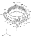
- FIG. 2 is a perspective view of the state in which the SMA assembly 36 is attached to the lens holder 18 as viewed from the upper right front.
- FIG. 3 is a perspective view of the state in which the SMA assembly 36 is stretched and attached to the lens holder 18 as viewed from the upper left rear.
- each electrode 34 is held by an electrode holding portion 146 a formed on the first base protruding portion 146.
- One shape memory alloy wire 32 is hooked by two holder / hook portions 184 formed on the second diagonal of the lens holder 18.
- one shape memory alloy wire 32 is hooked on a housing hook portion 148 a formed on the third base protruding portion 148.
- the shape memory alloy wire 32 is stretched between the lens holder 18 and the housing 12.
- a “shape memory alloy” is a metal having a property that a given deformation strain becomes zero and recovers to its original shape in a specific temperature region.
- the shape memory alloy is made of, for example, a TiNi alloy.
- the illustrated shape memory alloy wire 32 contracts to a pre-stored contraction length when self-heating is caused by energization, and to an original length (length in a relaxed state) predetermined by natural cooling when the energization is stopped. It is a return type wire.
- the elastic member 20 acts to urge the lens holder 18 downward along the optical axis O direction.
- the shape memory alloy wire 32 contracts when energized through a pair of electrodes 34 from a drive circuit (not shown). As a result, the lens holder 18 moves upward along the optical axis O direction against the downward biasing force of the elastic member 20.
- the shape memory alloy wire 32 is naturally cooled. As a result, the shape memory alloy wire 32 expands due to the downward biasing force of the elastic member 20. As a result, the lens holder 18 moves downward along the optical axis O direction.
- the shape memory alloy wire 32 expands and contracts in the direction of the optical axis O due to a temperature change caused by energization / non-energization, and functions as a moving means for moving the lens holder 18 in the direction of the optical axis O.
- the combination of the elastic member 20 and the SMA assembly 36 is a lens driving unit (20, 20) that drives the lens moving unit (11, 18) while supporting the lens moving unit (11, 18) so as to be movable in the optical axis O direction. 36).
- the lens driving unit (20, 36) and the lens movable unit (11, 18) are juxtaposed with respect to the optical axis O as shown in FIGS. Therefore, the lens driving device 10 can be reduced in height.
- the lens driving device 10 according to the first embodiment described above has the following effects.
- the first effect is that a sufficient amount of lens displacement can be secured.
- the reason is that one shape memory alloy wire 32 is extended so as to substantially circulate the outer periphery of the lens holder 18, so that the entire length of the shape memory alloy wire 32 can be increased. .
- the second effect is that the lens tilt can be reduced.
- one shape memory alloy wire 32 is hooked by two holder hook portions 184 formed on the second diagonal passing through the lens holder 18 perpendicular to the optical axis O. This is because the driving force of the lens holder 18 can be uniformly applied in the optical axis O direction (focus direction).
- one shape memory alloy wire 32 is used as one shape memory alloy member, but it is needless to say that the present invention is not limited to this.
- a plurality of shape memory alloy wires as shown in the second embodiment described later may be used, or shown in the third embodiment described later.
- a single shape memory alloy member formed in a coil shape may be used.
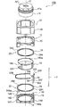
- FIG. 4 is an exploded perspective view of the lens driving device 10A as viewed obliquely from above and front.
- the illustrated lens driving device 10A is the same as the lens driving device 10 shown in FIGS. 1 to 3 except that the configuration of one shape memory alloy member (SMA assembly) is different as will be described later. It has a structure and operates. Accordingly, reference numerals 32A and 36A are assigned to the shape memory alloy member and the SMA assembly, respectively. The same components as those of the lens driving device 10 are denoted by the same reference numerals, description thereof will be omitted, and only differences will be described below.
- FIG. 5 is a perspective view of the state in which the SMA assembly 36A is stretched and attached to the lens holder 18 as viewed from the upper right front.
- FIG. 6 is an enlarged view showing an A portion of FIG.
- FIG. 7 is an enlarged cross-sectional view showing a portion B of FIG.
- the illustrated shape memory alloy member 32A is composed of three shape memory alloy wires 32-1, 32-2, and 32-3, each formed in a linear shape.
- the three shape memory alloy wires 32-1, 32-2, and 32-3 are bundled and used as a driving source. , Durability during lens driving can be improved.
- Durability during lens driving can be improved.
- the stress relating to the shape memory alloy member 32A is dispersed, and each shape is The memory alloy wires 32-1, 32-1, or 32-3 can have a stress dispersion effect of A / 3 [N].
- the lens driving device 10A having such a configuration operates in the same manner as the lens driving device 10 according to the first embodiment described above, the description of the operation is omitted.
- one shape memory alloy member 32A expands and contracts in the direction of the optical axis O due to a temperature change caused by energization / non-energization, and acts as a moving means for moving the lens holder 18 in the direction of the optical axis O.
- the combination of the elastic member 20 and the SMA assembly 36A is a lens driving unit (20, 20) that drives the lens moving unit (11, 18) while supporting the lens moving unit (11, 18) movably in the optical axis O direction. 36A).
- the lens driving unit (20, 36A) and the lens movable unit (11, 18) are juxtaposed with respect to the optical axis O as shown in FIG. Therefore, the lens driving device 10A can be reduced in height.
- the lens driving device 10A according to the second embodiment described above has the following effects.
- the first effect is that a sufficient amount of lens displacement can be secured.
- the reason is that since one shape memory alloy member 32A is extended so as to substantially make one round of the outer periphery of the lens holder 18, the entire length of the shape memory alloy member 32A can be increased. .
- the second effect is that the lens tilt can be reduced.
- one shape memory alloy member 32A is hooked by two holder hook portions 184 formed on a second diagonal passing through the lens holder 18 perpendicular to the optical axis O. This is because the driving force of the lens holder 18 can be uniformly applied in the optical axis O direction (focus direction).
- the third effect is that the durability when driving the lens can be improved.
- the reason is that one shape memory alloy member 32A is composed of three shape memory alloy wires 32-1, 32-2, and 32-3, so that stress can be dispersed.
- one shape memory alloy member 32A may be constituted by three shape memory alloy wires 32-1, 32-2, and 32-3.
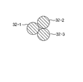
- FIG. 8 is a plan view showing a state in which the three shape memory alloy wires 32-1, 32-2, and 32-3 are held.
- FIG. 9 is a cross-sectional view taken along line IX-IX in FIG.
- one shape memory alloy member 32A is composed of three shape memory alloy wires 32-1, 32-2, and 32-3.
- N may be an integer of 2 or more) shape memory alloy wires 32-1 to 32-N.
- FIG. 10 is an exploded perspective view of the lens driving device 10B as viewed obliquely from above and front.
- the illustrated lens driving device 10B is the same as the lens driving device 10 shown in FIGS. 1 to 3 except that the configuration of one shape memory alloy member (SMA assembly) is different as will be described later. It has a structure and operates. Accordingly, the reference numerals 32B and 36B are assigned to the shape memory alloy member and the SMA assembly, respectively. The same components as those of the lens driving device 10 are denoted by the same reference numerals, description thereof will be omitted, and only differences will be described below.
- the illustrated shape memory alloy member 32B is composed of one shape memory alloy member formed in a coil shape.
- the illustrated shape memory alloy member 32B has a length of, for example, 10 mm when not stretched (natural state).
- the length of the shape memory alloy member 32B is, for example, 30 mm.
- the thickness (diameter) of the wire rod of the shape memory alloy member 32B is 36 ⁇ m.
- one shape memory alloy wire 32 formed in a linear shape contracts, for example, only about 4%, whereas in one shape memory alloy member 32B formed in a coil shape, for example, 200 % Or more can shrink. Therefore, compared with the lens driving device 10 according to the first embodiment, in the lens driving device 10B according to the third embodiment, the movable range (stroke) of the lens movable portion (11, 18) is increased. Can do.
- the lens driving device 10B having such a configuration operates in the same manner as the lens driving device 10 according to the first embodiment described above, description of the operation is omitted.
- the single shape memory alloy member 32B expands and contracts in the direction of the optical axis O due to a temperature change caused by energization / non-energization, and acts as a moving means for moving the lens holder 18 in the direction of the optical axis O.
- the combination of the elastic member 20 and the SMA assembly 36B is a lens driving unit (20, 20) that drives the lens moving unit (11, 18) while supporting the lens moving unit (11, 18) movably in the optical axis O direction. 36B).
- the lens driving unit (20, 36B) and the lens movable unit (11, 18) are juxtaposed with respect to the optical axis O. Accordingly, the lens driving device 10B can be reduced in height.
- the lens driving device 10B according to the third embodiment described above has the following effects.
- the first effect is that a sufficient amount of lens displacement can be secured.
- the reason is that since one shape memory alloy member 32B is extended so as to substantially make one round of the outer periphery of the lens holder 18, the entire length of the shape memory alloy member 32B can be increased. .
- the second effect is that the lens tilt can be reduced.
- one shape memory alloy member 32B is hooked by two holder hook portions 184 formed on the second diagonal passing through the lens holder 18 perpendicular to the optical axis O. This is because the driving force of the lens holder 18 can be uniformly applied in the optical axis O direction (focus direction).
- the third effect is that the lens displacement amount (the stroke of the lens movable portion) of the lens driving device 10B can be greatly increased.
- the reason is that since the single shape memory alloy member 32B is formed in a coil shape, the total length of the wire of the shape memory alloy member 32B can be made longer than that of the linear shape memory alloy wire 32. This is because the elastic force of the shape memory alloy member 32B can be improved.
- FIG. 11 is a perspective view of the external appearance of the lens driving device 10C as viewed obliquely from above and front.
- FIG. 12 is a perspective view of the lens driving device 10C as viewed obliquely from above and in the state where the outer upper cover 16A is omitted.
- FIG. 13 is an exploded perspective view of the lens driving device 10C as viewed obliquely from above and front.
- an orthogonal coordinate system (X, Y, Z) is used.
- the X-axis direction is the front-rear direction (depth direction)
- the Y-axis direction is the left-right direction (width direction)
- Z The axial direction is the vertical direction (height direction).
- the vertical direction Z is the direction of the optical axis O of the lens.
- the optical axis O direction that is, the Z-axis direction is the front-rear direction.
- the upward direction of the Z axis is the forward direction
- the downward direction of the Z axis is the backward direction.
- the illustrated lens driving device 10C has a structure that is plane-symmetric with respect to a plane that passes through the optical axis O and is defined by (extends) in the left-right direction Y and the up-down direction Z.
- the illustrated lens driving device 10C is provided, for example, in a camera-equipped mobile phone capable of autofocusing.
- the lens driving device 10C includes a lens barrel (lens assembly) 11 that incorporates an autofocus lens AFL that is a movable lens.
- the lens driving device 10C is for moving the lens barrel 11 only in the optical axis O direction.
- the lens driving device 10 ⁇ / b> C includes a substantially rectangular parallelepiped housing (housing) 12 ⁇ / b> A that covers the lens barrel 11.
- the lens barrel 11 is disposed in the housing (housing) 12A.
- the housing (housing) 12A includes an actuator base 14A and an outer upper cover 16A.
- the outer upper cover 16A has a substantially rectangular tube shape. That is, the outer upper cover 16A has a right wall surface 161, a left wall surface 162, a front wall surface 163, and a rear wall surface 164.
- the outer upper cover 16A has an upper wall surface 165 having a circular opening 165a at the upper end thereof.
- the right wall surface 161 is also referred to as a first side surface.
- an image sensor arranged on the substrate is mounted at the center of the actuator base 14A.
- This imaging device captures a subject image formed by the movable lens AFL and converts it into an electrical signal.
- the image pickup device is configured by, for example, a charge coupled device (CCD) image sensor, a complementary metal oxide (CMOS) image sensor, or the like.
- the lens driving device 10 ⁇ / b> C includes a lens holder 18 ⁇ / b> A that holds the lens barrel 11.
- the lens barrel 11 is held and fixed in the lens holder 18A.
- the lens holder 18A includes a cylindrical portion 182 having a substantially cylindrical shape.
- a female screw 182a is cut on the inner peripheral wall of the cylindrical portion 182 of the lens holder 18A.
- a male screw 11 a that is screwed into the female screw is cut on the outer peripheral wall of the lens barrel 11. Therefore, in order to attach the lens barrel 11 to the lens holder 18A, the lens barrel 11 is rotated around the optical axis O and screwed along the optical axis O direction with respect to the lens holder 18A. It is accommodated in the lens holder 18A and joined together by an adhesive or the like.
- the lens holder 18A is supported in the housing 12A so as to be movable only in the optical axis O direction, as will be described later.
- the lens movable portion (11, 18A) is configured by a combination of the lens barrel 11 and the lens holder 18A.
- each protrusion 184A is also called a latching protrusion or a holder hook part.
- the pair of projecting portions (holder / hook portions) 184A are radially outward from the tubular portion 182 at equal angular intervals of 180 ° about the optical axis O (opposite in the front-rear direction X). Protrusively arranged. That is, the two holder hook portions 184A are formed on the lens holder 18A on a straight line that passes through the first side surface 161 of the housing 12A and is orthogonal to the optical axis O.
- the actuator base 14A includes a ring-shaped base portion 142 and first to fourth base protruding portions 146A, 147A, 148A, and 149A that protrude upward in the vertical direction Z at the four corners of the base portion 142.
- the first base protrusion 146A is provided at the right front corner
- the second base protrusion 147A is provided at the left front corner
- the third base protrusion 148A is provided at the left rear corner
- the fourth base The protruding portion 149A is provided at the right rear corner.
- first to fourth base protrusions 146A to 149A have first to fourth sliding contact portions 146Aa to 149Aa that are in sliding contact with one shape memory alloy wire 32. Accordingly, the first to fourth base protrusions 146A to 149A are also referred to as first to fourth sliding contact protrusions, respectively.
- the first base protrusion (sliding protrusion) 146A is a first electrode holding portion 146Ab for holding one of a pair of electrodes 34 to be described later on the first side surface (right wall surface 161) side of the housing 12A.
- the fourth base protrusion (sliding protrusion) 149A is a second electrode holding portion 149Ab for holding the other of the pair of electrodes 34 on the first side surface (right wall surface 161) side of the housing 12A. including.
- the electrode holding portions 146Ab and 149Ab are formed on a pair of sliding contact protrusions 146A and 149A adjacent to each other on the first side surface 161 side of the housing 12A among the four sliding contact protrusions 146A to 149A. .
- the lens driving device 10C includes an upper leaf spring 26A and a lower leaf spring 28A provided on the upper and lower sides of the cylindrical portion 182 of the lens holder 18A in the optical axis O direction, respectively.
- the upper leaf spring 26A and the lower leaf spring 28A are arranged between the lens holder 18A and the housing 12A, and support the elastic member 20A so as to be displaceable in the optical axis O direction with the lens holder 18A positioned in the radial direction. Work as.
- the upward direction in the Z-axis direction (optical axis O direction) is the forward direction
- the downward direction in the Z-axis direction (optical axis O direction) is the backward direction. Therefore, the upper leaf spring 26A is also referred to as a front spring, and the lower leaf spring 28A is also referred to as a rear spring.
- the upper leaf spring 26A is disposed on the upper side in the optical axis O direction of the lens holder 18A, and the lower leaf spring 28A is disposed on the lower side in the optical axis O direction of the lens holder 18A.
- the upper leaf spring 26A has an upper ring portion 262A attached to the lens holder 18A and four upper end portions 264A attached to the four corners of the housing 12A as will be described later.
- Four upper arm portions 266 are provided between the upper ring portion 262A and the four upper end portions 264A. That is, the four upper arm portions 266 connect the upper ring portion 262A and the four upper end portions 264A.
- the upper ring portion 262A of the upper leaf spring 26A is fixed to the cylindrical portion 182 of the lens holder 18A.
- the lens holder 18 ⁇ / b> A has four upper holder protrusions 182 b that protrude upward from the upper end of the cylindrical part 182.
- the upper ring portion 262A of the upper leaf spring 26A has four upper spring holes 262Aa into which the four upper holder protrusions 182b are respectively inserted.
- each of the first to fourth base protrusions 146A to 149A includes four support protrusions (two support protrusions 146Ac formed on the first and third base protrusions 146A and 148A). Only 148Ac is shown in FIG. 14 and FIG.
- the four upper ends 264A of the upper leaf spring 26A have four upper end holes 264Aa into which the four support protrusions formed on the first to fourth base protrusions 146A to 149A are inserted, respectively.
- the housing 12A further includes a resin inner upper cover 30A provided inside the outer upper cover 16A.
- a bias spring 38 is disposed between the inner upper cover 30A and the upper leaf spring 26A.
- the bias spring 38 is for urging the lens holder 18A downward in the vertical direction Z.
- the bias spring 38 is for applying a downward back tension to the lens holder 18A.
- the bias spring 38 includes a ring portion 382 having the same diameter as the upper ring portion 262A of the upper leaf spring 26, and four biasing spring portions 384 extending obliquely upward from the ring portion 382.
- the four upper end portions 264A of the upper leaf spring 26A are fixed by the inner upper cover 30A and the bias spring 38.
- the housing 12A includes the actuator base 14A, the outer upper cover 16A, and the inner upper cover 30A.
- the lower leaf spring 28A has a lower ring portion 282A attached to the lens holder 18A and four lower end portions 284A attached to the housing 12A as will be described later.
- Four lower arm portions 286 are provided between the lower ring portion 282A and the four lower end portions 284A. That is, the four lower arm portions 286 connect the lower ring portion 282A and the four lower end portions 284A.
- the lower ring portion 282A of the lower leaf spring 28A is fixed to the cylindrical portion 182 of the lens holder 18A.
- the lens holder 18 ⁇ / b> A has four lower holder protrusions (not shown) that protrude downward from the lower end of the cylindrical portion 182.
- the lower ring portion 282A of the lower leaf spring 28A has four lower spring holes 282Aa into which the four lower holder protrusions are respectively inserted.
- the four lower end portions 284A of the lower leaf spring 28A are fixed to the base portion 142 of the actuator base 14A. More specifically, the base portion 142 has four support protrusions 142a (only two support protrusions are shown) protruding upward. Each of the four lower end portions 284A of the lower leaf spring 28A has four lower end hole 284Aa into which the four support protrusions 142 formed in the base portion 142 are fitted.
- the elastic member 20A composed of the upper leaf spring 26A and the lower leaf spring 28A serves as a guide means for guiding the lens holder 18A so as to be movable only in the direction of the optical axis O.
- Each of the upper leaf spring 26A and the lower leaf spring 28A is made of metal such as beryllium copper, phosphor bronze, and stainless steel.
- the plate springs 26A and 28A are manufactured by pressing a predetermined thin plate or etching using a photolithography technique. Note that the etching process is more preferable than the press process. This is because etching does not leave residual stress in the leaf spring.
- the lens movable portion (11, 18A) can move only in the optical axis O direction with respect to the housing (housing) 12A.
- the lens driving device 10 ⁇ / b> C includes a single shape memory alloy wire 32 formed in a linear shape and extending so as to substantially go around the outer periphery of the cylindrical portion 182 of the lens holder 18 ⁇ / b> A, and the shape memory alloy wire 32. And a pair of electrodes 34A electrically connected to both ends.
- the combination of the shape memory alloy (SMA) wire 32 and the pair of electrodes 34A is referred to as a shape memory alloy (SMA) assembly 36C.
- the pair of electrodes 34A is held by first and second electrode holding portions 146Ab and 149Ab formed on the first base protruding portion 146A and the fourth base protruding portion 149A, respectively.
- the pair of electrodes 34A has a symmetrical shape when viewed from the Y-axis direction.
- the pair of electrodes 34A extends substantially in the up-down direction Z.
- Each electrode 34A has a strip-shaped terminal portion 342A extending in the vertical direction Z, and a connection portion 344 bent in a U-shaped cross section at the upper end portion of the terminal portion 342A.
- Each electrode 34 ⁇ / b> A is electrically connected to the end of the shape memory alloy wire 32 by caulking the connection portion 344.
- the terminal portion 342A is for receiving a drive current from a drive circuit (not shown).
- the terminal portion 342A has a widened portion 342Aa.
- each of the first and second electrode holding portions 146Ab and 149Ab formed on the first and fourth base protruding portions 146A and 149A holds the widened portion 342Aa of the terminal portion 342A of the electrode 34A in sliding contact. It consists of a groove.
- FIG. 14 is a perspective view of the state in which the SMA assembly 36C is stretched and attached to the lens holder 18A, as viewed from the upper right front.
- FIG. 15 is a perspective view of the state in which the SMA assembly 36C is stretched and attached to the lens holder 18A, as viewed from the upper left rear.
- the pair of electrodes 34A are held by the first and second electrode holding portions 146Ab and 149Ab (see FIG. 13) formed on the first and fourth base protrusions 146A and 149A.
- one shape memory alloy wire 32 is hooked by two holder / hook portions 184A disposed opposite to each other in the front-rear direction X through the optical axis O of the lens holder 18A.
- one shape memory alloy wire 32 is slid onto the first to fourth slidable contact portions 146Aa to 149Aa of the first to fourth base protruding portions 146A to 149A. Touching.
- the shape memory alloy wire 32 is stretched between the lens holder 18A and the housing 12A.
- a “shape memory alloy” is a metal having a property that a given deformation strain becomes zero and recovers to its original shape in a specific temperature region.
- the shape memory alloy is made of, for example, a TiNi alloy.
- the illustrated shape memory alloy wire 32 contracts to a pre-stored contraction length when self-heating is caused by energization, and to an original length (length in a relaxed state) predetermined by natural cooling when the energization is stopped. It is a return type wire.
- the elastic member 20A supports the lens holder 18A so as to be displaceable in the optical axis O direction in a state where the lens holder 18A is positioned in the radial direction.
- the bias spring 38 acts to urge the lens holder 18A downward along the optical axis O direction.
- the shape memory alloy wire 32 contracts when energized via a pair of electrodes 34A from a drive circuit (not shown). As a result, the lens holder 18A moves upward along the direction of the optical axis O against the downward biasing force of the bias spring 38.
- the shape memory alloy wire 32 is naturally cooled. As a result, the shape memory alloy wire 32 expands due to the downward biasing force of the bias spring 38. As a result, the lens holder 18A moves downward along the optical axis O direction.
- the shape memory alloy wire 32 expands and contracts in the direction of the optical axis O due to a temperature change caused by energization / non-energization, and functions as a moving means for moving the lens holder 18A in the direction of the optical axis O.
- the combination of the elastic member 20A, the bias spring 38, and the SMA assembly 36C is a lens drive that drives the lens movable portion (11, 18A) while supporting the lens movable portion (11, 18A) movably in the optical axis O direction. Part (20A, 38, 36C).
- the lens driving unit (20A, 38, 36C) and the lens movable unit (11, 18A) are juxtaposed with respect to the optical axis O as shown in FIG. Therefore, the height of the lens driving device 10C can be reduced.
- the lens driving device 10C according to the fourth embodiment described above has the following effects.
- the first effect is that a sufficient amount of lens displacement can be secured.
- the reason is that one shape memory alloy wire 32 is extended so as to substantially make one round of the outer periphery of the lens holder 18A, so that the entire length of the shape memory alloy wire 32 can be increased. .
- the second effect is that the lens tilt can be reduced.
- one shape memory alloy wire 32 is hooked by two holder hook portions 184A formed on opposite sides through the optical axis O of the lens holder 18A. This is because the driving force can be uniformly applied in the optical axis O direction (focus direction).
- one shape memory alloy wire 32 is used as one shape memory alloy member.
- one shape memory alloy member is composed of a plurality of shape memory alloy wires 32-1 to 32-3 as shown in the second embodiment described with reference to FIGS.
- One shape memory alloy member 32A may be used, or one shape memory alloy member formed in a coil shape as shown in the third embodiment described with reference to FIG. 32B may be used.
- one shape memory alloy member 32A composed of a plurality of shape memory alloy wires 32-1 to 32-3, durability during lens driving can be improved. Further, by using one shape memory alloy member 32B formed in a coil shape, the lens displacement amount (the stroke of the lens movable portion) of the lens driving device 10C can be greatly increased.
- FIG. 16 is a perspective view of the external appearance of the lens driving device 10D as viewed obliquely from above and front.
- FIG. 17 is an exploded perspective view of the lens driving device 10D as viewed obliquely from above and front.
- FIG. 18 is a perspective view of the lens driving device 10D as viewed obliquely from above and from the upper front cover and the upper leaf spring.
- FIG. 19 is a perspective view of the lens driving device shown in FIG. 18 as viewed obliquely from above, omitting the actuator base and the lower leaf spring.
- an orthogonal coordinate system (X, Y, Z) is used.
- the X-axis direction is the front-rear direction (depth direction)
- the Y-axis direction is the left-right direction (width direction)
- Z The axial direction is the vertical direction (height direction).
- the vertical direction Z is the direction of the optical axis O of the lens.
- the optical axis O direction that is, the Z-axis direction is the front-rear direction.
- the upward direction of the Z axis is the forward direction
- the downward direction of the Z axis is the backward direction.
- the illustrated lens driving device 10D has a structure that is substantially plane-symmetric with respect to a plane that passes through the optical axis O and is defined by (extends) in the left-right direction Y and the vertical direction Z.
- the illustrated lens driving device 10D is provided, for example, in a camera-equipped mobile phone capable of autofocusing.
- the lens driving device 10D includes a lens barrel (lens assembly) 11 that incorporates an autofocus lens AFL that is a movable lens.
- the lens driving device 10D is for moving the lens barrel 11 only in the optical axis O direction.
- the lens driving device 10 ⁇ / b> D includes a substantially rectangular parallelepiped housing (housing) 12 ⁇ / b> B that covers the lens barrel 11.
- the lens barrel 11 is disposed in the housing (housing) 12B.
- the housing (housing) 12B includes an actuator base 14B and an upper cover 16B.
- the upper cover 16B has a substantially rectangular tube shape. That is, the upper cover 16B has a right wall surface 161A, a left wall surface 162A, a front wall surface 163A, and a rear wall surface 164A.
- the upper cover 16B has an upper wall surface 165A having a circular opening 165Aa at the upper end.
- the right wall surface 161A is also referred to as a first side surface.
- an image pickup device arranged on the substrate is mounted at the center of the actuator base 14B.
- This imaging device captures a subject image formed by the movable lens AFL and converts it into an electrical signal.
- the image pickup device is configured by, for example, a charge coupled device (CCD) image sensor, a complementary metal oxide (CMOS) image sensor, or the like.
- the lens driving device 10D includes a lens holder 18B that holds the lens barrel 11.
- the lens barrel 11 is held and fixed in the lens holder 18B.
- the lens holder 18B includes a cylindrical portion 182 having a substantially cylindrical shape.
- a female screw (not shown) is cut on the inner peripheral wall of the cylindrical portion 182 of the lens holder 18B.
- a male screw 11 a that is screwed into the female screw is cut on the outer peripheral wall of the lens barrel 11. Therefore, in order to attach the lens barrel 11 to the lens holder 18B, the lens barrel 11 is rotated around the optical axis O with respect to the lens holder 18B and screwed along the optical axis O direction. It is accommodated in the lens holder 18B and joined together by an adhesive or the like.
- the lens holder 18B is supported in the housing 12B so as to be movable only in the direction of the optical axis O, as will be described later.
- the lens movable portion (11, 18B) is configured by a combination of the lens barrel 11 and the lens holder 18B.
- each protrusion 184B is also called a latching protrusion or a holder hook part.
- the pair of projecting portions (holder / hook portions) 184B are radially outward from the cylindrical portion 182 at equal angular intervals of 180 ° centered on the optical axis O (opposite in the front-rear direction X). Protrusively arranged.
- the actuator base 14B includes a ring-shaped base portion 142 and first to fourth base protruding portions 146B, 147B, 148B, and 149B that protrude upward in the vertical direction Z at the four corners of the base portion 142.
- the first base protrusion 146B is provided at the right front corner
- the second base protrusion 147B is provided at the left front corner
- the third base protrusion 148B is provided at the left rear corner
- the fourth base The protruding portion 149B is provided at the right rear corner.
- the first base protruding portion 146B includes a first electrode holding portion 146Ba for holding one of a pair of electrodes 34B described later on the front surface of the housing 12B on the first side surface (right wall surface 161A) side.
- the fourth base protrusion 149B includes a second electrode holding portion 149Ba for holding the other of the pair of electrodes 34B on the rear surface of the housing 12B on the first side surface (right wall surface 161A) side.
- the lens driving device 10D includes an upper leaf spring 26B and a lower leaf spring 28B provided on the upper and lower sides of the cylindrical portion 182 of the lens holder 18B in the optical axis O direction, respectively.
- the upper plate spring 26B and the lower plate spring 28B are disposed between the lens holder 18B and the housing 12B, and support the elastic member 20B so as to be displaceable in the optical axis O direction with the lens holder 18B positioned in the radial direction. Work as.
- the upward direction in the Z-axis direction (optical axis O direction) is the forward direction
- the downward direction in the Z-axis direction (optical axis O direction) is the backward direction. Therefore, the upper leaf spring 26B is also referred to as a front spring, and the lower leaf spring 28B is also referred to as a rear spring.
- the upper leaf spring 26B is disposed on the upper side in the optical axis O direction of the lens holder 18B, and the lower leaf spring 28B is disposed on the lower side in the optical axis O direction of the lens holder 18B.
- the upper leaf spring 26B has an inner peripheral end 262 attached to the lens holder 18B and an outer peripheral end 264B attached to the inner wall of the upper wall 165A of the upper cover 16B.
- a plurality of arm portions (not shown) provided along the circumferential direction are provided between the inner peripheral side end portion 262 and the outer peripheral side portion 264B in order to connect them.
- the inner peripheral end 262 has an annular shape.
- the outer peripheral side end 264 ⁇ / b> B is provided to be spaced radially outward from the inner peripheral side end 262.
- the inner peripheral end of the outer peripheral end 264B is substantially circular, and the outer peripheral end is rectangular.
- Each arm portion extends along the circumferential direction.
- the inner peripheral side end 262 of the upper leaf spring 26B is fixed to the upper end of the cylindrical portion 182 of the lens holder 18B.
- the outer peripheral side end 264B of the upper leaf spring 26B is attached to the inner wall of the upper wall surface 165A of the upper cover 16B.
- the lower leaf spring 28B has an inner peripheral end 282 attached to the lens holder 18B and an outer peripheral end 284B attached to the actuator base 14B.
- a plurality of arm portions (not shown) provided along the circumferential direction are provided between the inner peripheral side end portion 282 and the outer peripheral side portion 284 ⁇ / b> B in order to connect them.
- the inner peripheral side end 282 has an annular shape.
- the outer peripheral side end portion 284B includes a ring portion 284Ba provided to be spaced radially outward from the inner peripheral side end portion 282, and four extensions extending from the ring portion 284Ba outward in the front, rear, left, and right directions in the radial direction. And an exit portion 284Bb.
- the inner peripheral side end 282 of the lower leaf spring 28B is fixed to the lower end side of the cylindrical portion 182 of the lens holder 18B by the adhesive force of the resin.
- the outer peripheral side end 284B of the lower leaf spring 28B is fixed on the base portion 142 of the actuator base 14B of the housing 12B.
- the elastic member 20B composed of the upper leaf spring 26B and the lower leaf spring 28B serves as a guide means for guiding the lens holder 18B so as to be movable only in the direction of the optical axis O.
- Each of the upper leaf spring 26B and the lower leaf spring 28B is made of metal such as beryllium copper, phosphor bronze, and stainless steel.
- These plate springs 26B and 28B are manufactured by pressing a predetermined thin plate or etching using a photolithography technique. Note that the etching process is more preferable than the press process. This is because no residual stress remains in the leaf spring in the etching process.
- the lens movable portion (11, 18B) can move only in the direction of the optical axis O with respect to the housing (housing) 12B.
- the lens driving device 10D includes a single shape memory alloy wire 32 formed in a linear shape and extending so as to substantially go around the outer periphery of the cylindrical portion 182 of the lens holder 18B, and the shape memory alloy wire 32. And a pair of electrodes 34B electrically connected to both ends.
- the combination of a shape memory alloy (SMA) wire 32 and a pair of electrodes 34B is referred to as a shape memory alloy (SMA) assembly 36D.
- the pair of electrodes 34B is held by first and second electrode holding portions 146Ba and 149Ba formed on the first base protruding portion 146B and the fourth base protruding portion 149B, respectively.
- the pair of electrodes 34B have a symmetrical shape when viewed from the Y-axis direction.
- the pair of electrodes 34B extends substantially in the up-down direction Z.
- Each electrode 34B has a strip-shaped terminal portion 342B extending in the up-down direction Z, and a connection portion 344A bent in a U-shaped cross section at the upper end portion of the terminal portion 342B.
- Each electrode 34B is electrically connected to the end of the shape memory alloy wire 32 by caulking the connecting portion 344A.
- the terminal portion 342B is for receiving a drive current from a drive circuit (not shown).
- each of the first and second electrode holding portions 146Ba and 149Ba formed on the first and fourth base protruding portions 146B and 149B is constituted by a groove for slidingly holding the terminal portion 342B of each electrode 34B.
- the lens holder 18B includes a first pair of urging latching protrusions 186 for latching a first urging shape memory alloy member 41, which will be described later, and a second urging shape memory alloy member 42, which will be described later.
- a second pair of biasing latching projections 187 for latching is further provided.
- the first pair of biasing projections 186 for urging project radially outward in front of the front-rear direction X on the outer peripheral wall of the cylindrical portion 182 of the lens holder 18B.
- the first pair of biasing protrusions 186 for urging are positioned above the front holder / hook portion 184 ⁇ / b> B in a state where two urging latching projections 186 are arranged in the left-right direction Y. More specifically, the first pair of biasing projections 186 for biasing are positioned on a line extending upward along the vertical direction Z through the holder / hook portion 184B on the front side.
- a pair of urging latching protrusions 186 are arranged.
- Each of the first pair of urging latching projections 186 protrudes in a hook shape along the vertical direction Z from the lower end side to the upper end side of the cylindrical portion 182.
- the first pair of urging latching protrusions 186 is for latching the intermediate portion 41a of the first urging shape memory alloy member 41 formed in a coil shape to be described later.
- the second pair of urging latching projections 187 protrudes outward in the radial direction behind the front-rear direction X on the outer peripheral wall of the cylindrical portion 182 of the lens holder 18B.
- the second pair of urging latching projections 187 are arranged above the rear holder / hook portion 184B in a state where two urging latching projections 187 are arranged in the left-right direction Y. More specifically, the second pair of biasing projections 187 for biasing is positioned on a line extending upward along the vertical direction Z through the rear holder / hook portion 184B.
- a pair of urging latching protrusions 187 are arranged.
- Each of the second pair of urging latching protrusions 187 protrudes in a hook shape along the vertical direction Z from the lower end side to the upper end side of the cylindrical portion 182.
- the second pair of urging latching protrusions 187 is for latching an intermediate portion 42a of a second urging shape memory alloy member 42 formed in a coil shape to be described later.
- the first urging shape memory alloy member 41 is disposed on the front upper side of the lens holder 18B, and the second urging shape memory alloy member 42 is disposed on the rear upper side of the lens holder 18B.
- the first energizing shape memory alloy member 41 has a first pair of alloy holding portions 412 attached to both ends thereof.
- the first pair of alloy holding portions 412 are fitted and held in alloy holding grooves 146Bb and 147Bb respectively formed in the first and second base protrusions 146B and 147B located on the front side.
- the first urging shape memory alloy member 41 has its intermediate portion 41a latched by the first pair of urging latching projections 186.
- the first urging shape memory alloy member 41 is not connected to the electrode and is not energized.
- the second energizing shape memory alloy member 42 has a second pair of alloy holding portions 422 attached to both ends thereof.
- the second pair of alloy holding portions 422 are fitted and held in alloy holding grooves 148Bb and 149Bb respectively formed in the third and fourth base protrusions 148B and 149B located on the rear side.
- the second urging shape memory alloy member 42 has its intermediate portion 42a latched by the second pair of urging latch projections 187. The second urging shape memory alloy member 42 is not connected to the electrode and is not energized.
- Each of the first and second urging shape memory alloys 41 and 42 is formed in a coil shape.
- Each of the illustrated first and second urging shape memory alloys 41 and 42 has a length of, for example, 3 mm when not stretched (natural state).
- the first and second urging shape memory alloys 41 and 42 are hooked on the urging latching protrusions (projections) 186 and 187 of the lens holder 18B, respectively.
- the lengths of the first and second urging shape memory alloys 41 and 42 are each 7 mm, for example.
- the thickness (diameter) of the wire of the first and second urging shape memory alloys 41 and 42 is 0.05 mm.
- the first and second urging shape memory alloys 41 and 42 when formed in a linear shape, the first and second urging shape memory alloys 41 and 42, for example, contract only about 4%, whereas in the case of being formed in a coil shape, The first and second urging shape memory alloys 41 and 42 can shrink, for example, by 200% or more.
- the one shape memory alloy wire 32 for driving and the first and second urging shape memory alloys 41 and 42 increase in temperature and contract in a high temperature environment. In, the temperature decreases and expands.
- the “high temperature environment” mentioned here means an environment where the external temperature is about 70 ° C. or higher when, for example, a TiNi alloy is adopted as the shape memory alloy.
- the “normal temperature environment” means an environment where the external temperature is about 70 ° C. or less when, for example, a TiNi alloy is used as the shape memory alloy.
- a “shape memory alloy” is a metal having a property that a given deformation strain becomes zero and recovers to its original shape in a specific temperature region.
- the shape memory alloy is made of, for example, a TiNi alloy.
- the single shape memory alloy wire 32 shown in the drawing contracts to a pre-stored contraction length when self-heating is caused by energization, and when the energization is stopped, the original length predetermined by natural cooling (the length of the relaxed state). This is the type of wire that goes back to (a).
- the elastic member 20B supports the lens holder 18B so as to be displaceable in the optical axis O direction in a state where the lens holder 18B is positioned in the radial direction.
- the elastic member 20B and the first and second urging shape memory alloys 41 and 42 act to urge the lens holder 18B downward along the optical axis O direction.
- the shape memory alloy wire 32 contracts when energized through a pair of electrodes 34B from a drive circuit (not shown). As a result, the lens holder 18B moves upward along the optical axis O direction against the downward biasing force of the elastic member 20B and the first and second biasing shape memory alloys 41, 42.
- the shape memory alloy wire 32 is naturally cooled.
- the shape memory alloy wire 32 is stretched by the downward biasing force of the elastic member 20B and the first and second biasing shape memory alloys 41,.
- the lens holder 18B moves downward along the optical axis O direction.
- the shape memory alloy wire 32 expands and contracts in the direction of the optical axis O due to a temperature change caused by energization / non-energization, and functions as a moving means for moving the lens holder 18B in the direction of the optical axis O.
- the combination of the elastic member 20B, the first and second urging shape memory alloys 41, 42, and the SMA assembly 36D allows the lens movable portion (11, 18B) to be supported while being movable in the optical axis O direction. It works as a lens driving part (20B, 41, 42, 36D) for driving the movable part (11, 18B).
- the lens driving unit (20B, 41, 42, 36D) and the lens movable unit (11, 18B) are juxtaposed with respect to the optical axis O as shown in FIG. Accordingly, the lens driving device 10D can be reduced in height.
- the lens movable portion (11, 18B) is moved in the direction of the optical axis O.
- the biasing spring that biases the lens movable portion (11, 18B) downward along the optical axis O direction can be adjusted.
- the shape memory alloy wire 32 contracts as its temperature rises as described above.
- the first and second urging shape memory alloys 41 and 42 similarly increase in temperature and contract. Accordingly, the thrust of the shape memory alloy wire 32 acting on the lens movable portion (11, 18B) toward the upper side in the optical axis O direction acts on the lens movable portion (11, 18B) toward the lower side in the optical axis O direction. Since the thrusts of the first and second urging shape memory alloys 41 and 42 increase (or become equal), the displacement of the lens movable portion (11, 18B) in the upward direction in the optical axis O direction can be prevented.
- the first and second urging shape memory alloys 41 and 42 are thrust adjusting means (thrust compensating means) for adjusting (compensating) the thrust acting on the lens movable portion (11, 18B) in a high temperature environment. ).
- the first and second biasing shape memory alloys 41 and 42 function as temperature compensation means.
- the temperature of the shape memory alloy wire 32 increases and contracts, and a lens holder is interposed via a pair of latching protrusions (holder / hook portions) 184B. 18B is moved upward in the direction of the optical axis O.
- the first and second urging shape memory alloys 41 and 42 are not energized as described above, they act only as urging springs that urge downward.
- the lens holder 18B moves upward along the optical axis O direction against the downward biasing force of the elastic member 20B and the first and second biasing shape memory alloys 41, 42.
- the shape memory alloy wire 32 is naturally cooled.
- the shape memory alloy wire 32 expands, and the lens holder 18B moves in the direction of the optical axis O by the downward biasing force of the elastic member 20B and the first and second biasing shape memory alloys 41 and 42. Move down along.
- the lens driving device 10D according to the fifth embodiment described above has the following effects.
- the first effect is that a sufficient amount of lens displacement can be secured.
- the reason is that one shape memory alloy wire 32 is extended so as to substantially circulate around the outer periphery of the lens holder 18B, so that the entire length of the shape memory alloy wire 32 can be increased. .
- the second effect is that the lens tilt can be reduced.
- one shape memory alloy wire 32 is hooked by two holder hook portions 184B formed on the opposite sides through the optical axis O of the lens holder 18B. This is because the driving force can be uniformly applied in the optical axis O direction (focus direction).
- the third effect is that the displacement of the lens movable portion (11, 18B) in the optical axis O direction can be prevented (compensated) in a high temperature environment.
- the reason is that the first and second urging shape memory alloy members 41 and 42 functioning as temperature compensating means are installed as the lens driving unit.
- the fourth effect is that the displacement of the lens movable portion (11, 18B) in the direction of the optical axis O in a high temperature environment can be reliably prevented.
- the reason is that the first and second urging shape memory alloy members 41 and 42 acting as temperature compensating means are formed in a coil shape, so that the shape memory alloy wire 32 for driving contracts in a high temperature environment. This is because the contraction of the first and second urging shape memory alloy members 41 and 42 becomes larger, and the downward driving force along the optical axis O direction becomes larger.
- one shape memory alloy wire 32 is used as one shape memory alloy member.
- one shape memory alloy member is composed of a plurality of shape memory alloy wires 32-1 to 32-3 as shown in the second embodiment described with reference to FIGS.
- One shape memory alloy member 32A may be used, or one shape memory alloy member formed in a coil shape as shown in the third embodiment described with reference to FIG. 32B may be used.
- one shape memory alloy member 32A composed of a plurality of shape memory alloy wires 32-1 to 32-3, durability during lens driving can be improved. Further, by using one shape memory alloy member 32B formed in a coil shape, the lens displacement amount (stroke of the lens movable portion) of the lens driving device 10D can be greatly increased.
- the elastic member 20B (the upper leaf spring 26B, the upper plate spring 26B) is used to hold the lens movable portion (11, 18B) and apply a back tension to the lens movable portion (11, 18B).
- the lower leaf spring 28B and the first and second urging shape memory alloy members 41 and 42 are provided, it is of course not limited thereto.
- the elastic member 20B (the upper leaf spring 26B, the lower leaf spring 28B) is omitted, and the lens movable portion (11, 18B) is held only by the first and second urging shape memory alloy members 41, 42, You may make it provide a back tension with respect to a lens movable part (11, 18B).
- the moving means is attached to both ends of one shape memory alloy member, and has a pair of electrodes for energizing one shape memory alloy member. You may also have.
- the housing may include an actuator base disposed on the lower side of the lens holder, and the actuator base may include an electrode holding portion that holds a pair of electrodes.
- N is equal to 2
- the housing has a substantially bottomed rectangular tube shape
- the electrode holding portions are the first corners of the housing. May be formed as a protrusion protruding upward from the actuator base.
- the housing has one shape memory alloy member at the second corner of the four corners of the housing opposite to the first corner on the first diagonal passing through the optical axis at right angles.
- the two holder hook portions are formed in the lens holder on a second diagonal line that passes perpendicularly to the optical axis and intersects the first diagonal line. It is preferable.
- N is equal to 2
- the housing has a substantially bottomed rectangular tube shape
- the actuator base is located at the four corners of the housing.
- You may have four sliding contact protrusions which protrude to and come into sliding contact with one shape memory alloy member.
- the electrode holding portion is formed in a pair of sliding contact protrusions adjacent to each other on the first side surface side of the housing among the four sliding contact protrusions, and the two holder hook portions are It is preferable that the lens holder is formed on a straight line passing through the first side surface of the housing and parallel to the optical axis.
- one shape memory alloy member may be composed of one shape memory alloy wire formed in a linear shape.
- one shape memory alloy member may be composed of a plurality of shape memory alloy wires each formed in a linear shape.
- the plurality of shape memory alloy wires are preferably wound.
- one shape memory alloy member may be composed of one shape memory alloy member formed in a coil shape.
- the guide means may include, for example, an elastic member disposed between the lens holder and the housing.
- the elastic member supports the lens holder so as to be displaceable only in the optical axis direction with the lens holder positioned in the radial direction.
- the elastic member is preferably composed of an upper leaf spring and a lower leaf spring provided respectively on the upper and lower sides of the cylindrical portion of the lens holder in the optical axis direction.
- the guide means (elastic member; leaf spring) is not limited to the above-described embodiment, and various types may be used.
- the lens holder includes two holder hook portions arranged so as to protrude in the radial direction from the cylindrical portion 182 at equal angular intervals of 180 ° with the optical axis O as the center.
- the number of holder / hook portions is not limited to two, and may generally be N (N is an integer of 2 or more).
- the N holder hook portions are arranged so as to protrude in the radial direction from the cylindrical portion 182 at an equal angular interval of (360 ° / N) with the optical axis O as the center.
Landscapes
- Engineering & Computer Science (AREA)
- General Engineering & Computer Science (AREA)
- Physics & Mathematics (AREA)
- Chemical & Material Sciences (AREA)
- Combustion & Propulsion (AREA)
- General Physics & Mathematics (AREA)
- Optics & Photonics (AREA)
- Mechanical Engineering (AREA)
- Lens Barrels (AREA)
Abstract
十分なレンズ変位量を確保することが可能なレンズ駆動装置を提供する。レンズ駆動装置は、レンズバレルを保持する筒状部を含むレンズホルダと、このレンズホルダを光軸方向にのみ移動可能に支持するハウジングと、レンズホルダを光軸方向に移動させる移動手段と、レンズホルダを光軸方向にのみ移動可能に案内する案内手段と、を備える。移動手段は、レンズホルダの外周を実質的に一周するように延在し、かつレンズホルダとハウジングとの間に張架された1本の形状記憶合金部材を含む。レンズホルダは、光軸を中心とした(360°/N)(Nは2以上の整数)の等角度間隔で筒状部から半径方向外側へ突出して配置され、1本の形状記憶合金部材を掛止するN個のホルダ・フック部を含む。
Description
本発明はレンズ駆動装置に関し、特に、アクチュエータに形状記憶合金を用いたレンズ駆動装置に関する。
カメラのオートフォーカス用アクチュエータやズーム用アクチュエータとして、形状記憶合金(Shape Memory Alloy:SMA)を使用した駆動装置(リニアアクチュエータ)が知られている。
例えば、WO2007/113478A1(特許文献1)は、1つのサスペンションシステムによって1つの支持構造体(ハウジング)によって支持された1つのカメラレンズの運動を駆動する「カメラレンズ駆動装置」を開示している。特許文献1に開示されたカメラレンズ駆動装置は、支持構造体に取り付けられた少なくとも1つの取付部材に接続されたSMAワイヤを有するサブアセンブリを組み込んでいる。少なくも2本のSMAワイヤは、光軸に沿った成分を持つ張力を加える光軸に対してそれぞれ鋭角で、カメラレンズ要素と支持構造体(ハウジング)との間にテンションをもって保持されている。2本のSMAワイヤは、光軸に沿って見たとき、角度をもって保持されている。サブアセンブリは、SMAワイヤをカシメによって接続された取付部材を有する。取付部材はSMAワイヤに電気的に接続されている。したがって、取付部材は電極として働く。取付部材(電極)は、支持構造体(環状壁)に形成されたくぼみに取り付けられている。
また、特開2007-292864号公報(特許文献2)は、伝達効率を向上し、コンパクト化を図った「レンズ駆動装置」を開示している。この特許文献2に開示されたレンズ駆動装置は、固定鏡筒(ハウジング)と、光学系を構成する一部又は全部のレンズ群(レンズバレル)を保持するレンズ枠(レンズホルダ)と、固定鏡筒に対してレンズ枠(レンズホルダ)を光軸方向に移動自在に支持するガイド手段と、レンズ枠を光軸方向のうち一方に向けて付勢する付勢手段とを備える。レンズ駆動装置は、固定鏡筒に対してレンズ枠を付勢手段の付勢に抗して他方に向けて移動させる。
この特許文献2に開示されたレンズ駆動装置は、形状記憶合金(SMA)ワイヤと、ワイヤ軸受け部材とを備える。SMAワイヤは、両端が固定鏡筒に固定されており、通電により加熱されることで予め決められた弛緩状態の長さよりも縮まる。
特許文献2に開示されたレンズ駆動装置の実施形態では、SMAワイヤは、一対のワイヤ支持部材に両端が固定されて、一対のワイヤ支持部材は、固定鏡筒(ハウジング)に固定されている。通電制御部は、一対のワイヤ支持部材を介してSMAワイヤの両端に通電を行う。従って、ワイヤ支持部材は電極として働く。
特開2009-19507号公報(特許文献3)は、製造効率を向上しつつ、組立精度のバラツキを低減することができるようにした、「駆動モジュール」を開示している。
この特許文献3に開示された駆動モジュールは、シャーシ(ハウジング;支持体)上に移動可能に設けられた被駆動体(レンズホルダ)が、通電量に応じて伸縮する形状記憶合金(SMA)ワイヤの中間部に係止されてなる。駆動モジュールは一対の保持端子を備え、シャーシ(ハウジング;支持体)は、位置決め部と係止部とを備える。
特開2009-128736号公報(特許文献4)は、落下などによる衝撃力による破損や故障の可能性を低減するとともに、小型化を図ることができるようにした、「駆動モジュール」を開示している。
この特許文献4に開示された駆動モジュールは、レンズ枠と、このレンズ枠の内側に収容するモジュール枠と、上板ばねと、レンズ枠を上板ばねの付勢力に抗して、一定方向に沿って駆動するSMAワイヤとを備える。レンズ枠の径方向外側には、径方向外方に突出するようにガイド突起が設けられている。モジュール枠の一隅の下部には切欠きが形成されている。この切欠きの平面視の溝幅は、レンズ枠のガイド突起に軸方向に移動可能に嵌合する大きさを有する。モジュール枠の切欠きに隣接する2つの隅部には、一対の係止溝が設けられている。これら一対の係止溝は、切欠きが設けられた隅部と同方向側の側面において、SMAワイヤを保持する一対のワイヤ保持部材を取り付けるためのものである。一対のワイヤ保持部材によって両端が保持されたSMAワイヤは、モジュール枠の切欠きから突出されたレンズ枠のガイド突起の先端鍵部に下方から係止されている。
また、特開2006-98829号公報(特許文献5)は、レンズを円滑にかつ速やかに移動することができると共に、携帯情報端末機に組み込み可能に小型化された「レンズ駆動装置」を開示している。
この特許文献5に開示されたレンズ駆動装置は、レンズ枠を光軸方向の前側及び後側から付勢するべく当接して配置された前側コイルバネおよび後側コイルバネを含む。前側コイルバネおよび後側コイルバネの少なくとも一方は、形状記憶合金から成る。尚、特許文献5では、前側コイルバネ及び後側コイルバネの双方を形状記憶合金製としてもよいことが記載されている。そして、前側コイルバネ及び後側コイルバネの双方を形状記憶合金製とする場合には、一方が通電加熱されて伸長するときに、他方は通電過熱されて収縮する構成とすればよい、と記載している。すなわち、前側コイルバネ及び後側コイルバネの双方が、駆動用のバネとして作用している。
前述した特許文献1~4には、それぞれ、以下に説明するような問題点がある。
特許文献1に開示されたカメラレンズ駆動装置では、2本のSMAワイヤが取付部材で保持されている。したがって、各SMAワイヤの長さを長くすることができず、十分なレンズ変位量を確保することが困難となる。
特許文献2に開示されたレンズ駆動装置では、1本のSMAワイヤが、固定鏡筒の一側面側にのみ配置されている。そのため、SMAワイヤの長さを長くすることができず、十分なレンズ変位量を確保することが困難となる。
特許文献3に開示された駆動モジュールでも、1本の形状記憶合金(SMA)ワイヤが被駆動体(レンズホルダ)の一側面側にのみ配置されている。そのため、SMAワイヤの長さを長くすることができず、十分なレンズ変位量を確保することが困難となる。
特許文献4に開示された駆動モジュールでは、1本のSMAワイヤがモジュール枠の2側面に配置されている。そのため、SMAワイヤの長さを長くすることができず、十分なレンズ変位量を確保することが困難となる。
また、特許文献1~4のいずれも、形状記憶合金部材として線状に形成された形状記憶合金ワイヤを使用している。その結果、レンズ駆動装置のレンズ変位量に限界がある。換言すれば、レンズ駆動装置のレンズ変位量が形状記憶合金ワイヤの変位量に左右されてしまう。
尚、特許文献5は、前側コイルバネ及び後側コイルバネの双方を駆動用のバネとして使用してもよいことを開示しているに過ぎない。
したがって、本発明の目的は、十分なレンズ変位量を確保することができる、レンズ駆動装置を提供することにある。
本発明の他の目的は、説明が進むにつれて明らかになるだろう。
本発明の典型的な態様の要点にいて述べると、レンズ駆動装置は、レンズバレルを保持する筒状部を含むレンズホルダと、このレンズホルダを光軸方向にのみ移動可能に支持するハウジングと、レンズホルダを光軸方向に移動させる移動手段と、レンズホルダを光軸方向にのみ移動可能に案内する案内手段と、を備える。本発明の典型的な態様によれば、移動手段は、レンズホルダの外周を実質的に一周するように延在し、かつレンズホルダとハウジングとの間に張架された1本の形状記憶合金部材を含む。レンズホルダは、光軸を中心とした(360°/N)(Nは2以上の整数)の等角度間隔で筒状部から半径方向外側へ突出して配置され、1本の形状記憶合金部材を掛止するN個のホルダ・フック部を含む。
本発明では、移動手段である1本の形状記憶合金部材が、レンズホルダの外周を実質的に一周するように延在しているので、形状記憶合金ワイヤの長さを長くすることができ、十分なレンズ変位量を確保することができる。
以下、図面を参照して、本発明の実施の形態について説明する。
図1を参照して、本発明の第1の実施の形態によるレンズ駆動装置10について説明する。図1はレンズ駆動装置10を斜め前方上方から観た分解斜視図である。
ここでは、図1に示されるように、直交座標系(X,Y,Z)を使用している。図1に図示した状態では、直交座標系(X,Y,Z)において、X軸方向は前後方向(奥行方向)であり、Y軸方向は左右方向(幅方向)であり、Z軸方向は上下方向(高さ方向)である。図1に示す例においては、上下方向Zがレンズの光軸O方向である。
但し、実際の使用状況においては、光軸O方向、すなわち、Z軸方向が前後方向となる。換言すれば、Z軸の上方向が前方向となり、Z軸の下方向が後方向となる。
図示のレンズ駆動装置10は、光軸Oに対して直交して通過し、かつ上下方向Zおよび右前と左後とを通過する第1の対角線方向によって規定される(に延在する)平面に対して実質的に面対称の構造を有する。
図示のレンズ駆動装置10は、例えば、オートフォーカス可能なカメラ付き携帯電話機に備えられる。レンズ駆動装置10は、可動レンズであるオートフォーカスレンズAFLを内蔵するレンズバレル(レンズアセンブリ)11を含む。レンズ駆動装置10は、レンズバレル11を光軸O方向にのみ移動させるためのものである。
図1に示されるように、レンズ駆動装置10は、レンズバレル11を覆う略直方体形状の筐体(ハウジング)12を備える。換言すれば、筐体(ハウジング)12内に、レンズバレル11が配置される。筐体(ハウジング)12は、アクチュエータ・ベース14と、外上側カバー16とを含む。
ハウジング12は四隅を持つ。ここでは、これら四隅の内、右前の隅を第1の隅と呼び、左後の隅を第2の隅と呼ぶことにする。
一方、図示はしないが、アクチュエータ・ベース14の中央部には、基板に配置された撮像素子が搭載される。この撮像素子は、可動レンズAFLにより結像された被写体像を撮像して電気信号に変換する。撮像素子は、例えば、CCD(charge coupled device)型イメージセンサ、CMOS(complementary metal oxide semiconductor)型イメージセンサ等により構成される。
レンズ駆動装置10は、上記レンズバレル11を保持するレンズホルダ18を含む。換言すれば、レンズバレル11はレンズホルダ18内に保持・固定される。詳述すると、レンズホルダ18は略円筒状をした筒状部182を含む。レンズホルダ18の筒状部182の内周壁には雌ネジ182aが切られている。一方、レンズバレル11の外周壁には、上記雌ネジに螺合される雄ネジ11aが切られている。従って、レンズバレル11をレンズホルダ18に装着するには、レンズバレル11をレンズホルダ18に対して光軸O周りに回転して光軸O方向に沿って螺合することにより、レンズバレル11をレンズホルダ18内に収容し、接着剤などによって互いに接合する。
レンズホルダ18は、ハウジング12内で、後述するように、光軸O方向にのみ移動可能に支持される。レンズバレル11とレンズホルダ18との組み合わせによってレンズ可動部(11,18)が構成される。
レンズホルダ18の筒状部182の外周壁には、光軸Oに対して直交して通過し、かつ上記第1の対角線方向と交差(直交)する(すなわち、左前と右後とを通過する)第2の対角線方向で、半径方向外側に突出する2個のホルダ・フック部184(図1では、左前にある1個のホルダ・フック部のみ図示している)を有する。これら2個のホルダ・フック部184は、後述する線状に形成された1本の形状記憶合金ワイヤ32を掛止するためのものである。
換言すれば、一対の突出部(ホルダ・フック部)184は、光軸Oを中心とした180°の等角度間隔で(第2の対角線方向で対向して)、筒状部182から半径方向外側へ突出して配置されている。
アクチュエータ・ベース14は、リング状のベース部142と、ベース部142の四隅で上下方向Zの上方へ突出する第1乃至第4のベース突出部146、147、148、および149とを有する。第1のベース突出部146は右前角部に設けられ、第2のベース突出部147は左前角部に設けられ、第3のベース突出部148は左後角部に設けられ、第4のベース突出部149は右後角部に設けられている。したがって、第1のベース突出部146と第3のベース突出部148とは、光軸Oを間に挟んで、第1の対角線上で互いに反対側に(対向して)配置されている。
第1のベース突出部146は、後述する一対の電極34を保持するための電極保持部146aを含む。一方、第3のベース突出部148は、上記1本の形状記憶合金ワイヤ32を引っ掛けるためのハウジング・フック部148aを含む。
従って、電極保持部146aは、ハウジング12の第1の隅に形成され、ハウジング・フック部148aは、ハウジング12の第2の隅に形成されている。
レンズ駆動装置10は、レンズホルダ18の筒状部182の光軸O方向の上側および下側にそれぞれ設けられた上側板バネ26と下側板バネ28とを備える。上側板バネ26と下側板バネ28とは、レンズホルダ18とハウジング12との間に配置されて、レンズホルダ18を径方向に位置決めした状態で光軸O方向に変位可能に支持する弾性部材20として働く。
また、前述したように、実際の使用状況においては、Z軸方向(光軸O方向)の上方向が前方向、Z軸方向(光軸O方向)の下方向が後方向となる。したがって、上側板バネ26は前側スプリングとも呼ばれ、下側板バネ28は後側スプリングとも呼ばれる。
上側板バネ26はレンズホルダ18における光軸O方向上側に配置され、下側板バネ28はレンズホルダ18における光軸O方向下側に配置される。上側板バネ26と下側板バネ28とは、実質的に同一構成をしている。
上側板バネ26は、レンズホルダ18に取り付けられる内周側端部262と、後述するようにハウジング12に取り付けられる外周側端部264とを有する。内周側端部262と外周側部264との間には、それらの間を連結するために周方向に沿って設けられた複数のアーム部(図示せず)が設けられている。内周側端部262は円環状をしている。外周側端部264は、内周側端部262から離間して設けられ、内周側端部262よりも大きい八角環状をしている。各アーム部は周方向に沿って延出している。
上側板バネ26の内周側端部262は、レンズホルダ18の筒状部182の上端に固定される。
一方、上側板バネ26の外周側端部264は、後述するように、ハウジング12に固定される。詳述すると、ハウジング12は、外上側カバー16の内部に設けられた樹脂製の内上側カバー30を更に有する。この内上側カバー30によって、上側板バネ26の外周側端部264が固定される。
従って、ハウジング12は、アクチュエータ・ベース14、外上側カバー16、および内上側カバー30から構成される。
同様に、下側板バネ28は、レンズホルダ18に取り付けられる内周側端部282と、後述するようにハウジング12に取り付けられる外周側端部284とを有する。内周側端部282と外周側部284との間には、それらの間を連結するために周方向に沿って設けられた複数のアーム部(図示せず)が設けられている。内周側端部282は円環状をしている。外周側端部284は、内周側端部282から離間して設けられ、内周側端部282よりも大きい八角環状をしている。各アーム部は周方向に沿って延出している。
下側板バネ28の内周側端部282は、レンズホルダ18の筒状部182の下端側に樹脂の接着力で固定されている。一方、下側板バネ28の外周側端部284は、ハウジング12のアクチュエータ・ベース14のベース部142に固定される。
尚、内周側端部262、282は内輪とも呼ばれ、外周側端部264、284は外輪とも呼ばれる。
上側板バネ26と下側板バネ28とから成る弾性部材20は、レンズホルダ18を光軸O方向にのみ移動可能に案内する案内手段として働く。上側板バネ26および下側板バネ28の各々は、ベリリウム銅、リン青銅、ステンレス鋼等の金属製である。これら板バネ26、28は、所定の薄板に対するプレス加工、あるいはフォトリソグラフィ技術を用いたエッチング加工により製造される。尚、プレス加工よりもエッチング加工の方が好ましい。何故なら、エッチング加工では板バネに残留応力が残らないからである。
このような構成により、レンズ可動部(11,18)は、筐体(ハウジング)12に対して光軸O方向にのみ移動可能である。
レンズ駆動装置10は、レンズホルダ18の筒状部182の外周を実質的に一周するように延在する、線状に形成された1本の形状記憶合金ワイヤ32と、この形状記憶合金ワイヤ32の両端部にそれぞれ電気的に接続された一対の電極34とを備えている。1本の形状記憶合金ワイヤ32は、レンズホルダ18とハウジング12との間に張架されている。図示の例では、1本の形状記憶合金ワイヤ32の線径(太さ)は36μmである。形状記憶合金(SMA)ワイヤ32と一対の電極34との組み合わせは、形状記憶合金(SMA)アセンブリ36と呼ばれる。一対の電極34は、第1のベース突出部146に形成された電極保持部146aによって保持される。
一対の電極34は、実質的に同一の形状をしている。各電極34は、実質的に上下方向Zに延在している。各電極34は、上下方向Zに延在する帯状の端子部342と、この端子部342の上端部で断面コ字状に曲げられた接続部344とを有する。各電極34は、接続部344をかしめて、形状記憶合金ワイヤ32の端部と電気的に接続される。端子部342は、図示しない駆動回路からの駆動電流の供給を受けるためのものである。
一方、第1のベース突出部146に形成された電極保持部146aは、各電極34の端子部342を摺接して保持する溝と、端子部342が貫通する貫通孔とから構成されている。
次に、図2及び図3を参照して、SMAアセンブリ36をレンズホルダ18に対して張架して取付けた状態について説明する。図2は、SMAアセンブリ36をレンズホルダ18に対して張架して取り付けた状態を、右前方上方から観た斜視図である。図3は、SMAアセンブリ36をレンズホルダ18に対して張架して取り付けた状態を、左後方上方から観た斜視図である。
図2に示されるように、各電極34は、第1のベース突出部146に形成された電極保持部146aに保持されている。また、1本の形状記憶合金ワイヤ32は、レンズホルダ18の第2の対角線上に形成された2個のホルダ・フック部184で掛止されている。
一方、図3に示されるように、1本の形状記憶合金ワイヤ32は、第3のベース突出部148に形成されたハウジング・フック部148aに引っ掛けられている。
このようにして、形状記憶合金ワイヤ32は、レンズホルダ18とハウジング12との間に張架されている。
次に、レンズ駆動装置10の概略の動作について説明する。
周知のように、「形状記憶合金」とは、予め与えられた変形歪が、特定の温度領域において、ゼロとなって元の形状に回復する性質を持つ金属である。形状記憶合金は、例えば、TiNi合金からなる。
尚、図示の形状記憶合金ワイヤ32は、通電により自己発熱すると予め記憶された収縮長さに収縮し、通電を止めると自然冷却により予め決められた元の長さ(弛緩状態の長さ)に戻るタイプのワイヤである。
上記弾性部材20は、レンズホルダ18を光軸O方向に沿って下方向に付勢するように作用する。一方、形状記憶合金ワイヤ32は、駆動回路(図示せず)から一対の電極34を介して通電されると、収縮する。その結果、レンズホルダ18は、弾性部材20の下方向の付勢力に抗して、光軸O方向に沿って上方へ移動する。
一方、形状記憶合金ワイヤ32への通電を停止すると、形状記憶合金ワイヤ32は自然に冷却される。その結果、弾性部材20の下方向の付勢力により、形状記憶合金ワイヤ32は、伸張する。その結果、レンズホルダ18は、光軸O方向に沿って下方へ移動する。
すなわち、形状記憶合金ワイヤ32は、その通電/非通電による温度変化により光軸O方向に伸縮し、レンズホルダ18を光軸O方向に移動させる移動手段として働く。
弾性部材20とSMAアセンブリ36との組み合わせは、レンズ可動部(11,18)を光軸O方向に移動可能に支持しながら、レンズ可動部(11,18)を駆動するレンズ駆動部(20,36)として働く。
レンズ駆動部(20,36)とレンズ可動部(11,18)とは、図2、図3に示されるように、光軸Oに対して並置されている。したがって、レンズ駆動装置10を低背化することができる。
上述した第1の実施の形態に係るレンズ駆動装置10は、次に述べるような効果を奏する。
第1の効果は、十分なレンズ変位量を確保することができることである。その理由は、1本の形状記憶合金ワイヤ32を、レンズホルダ18の外周を実質的に一周するように延在させているので、形状記憶合金ワイヤ32の全長を長くとることができるからである。
第2の効果は、レンズ傾きを小さくすることができることである。その理由は、1本の形状記憶合金ワイヤ32を、レンズホルダ18の光軸Oと直交して通過する第2の対角線上に形成した2個のホルダ・フック部184で掛止しているので、レンズホルダ18の推進力を均一に光軸O方向(フォーカス方向)に与えることができるからである。
尚、上記第1の実施の形態では、1本の形状記憶合金部材として1本の形状記憶合金ワイヤ32を使用しているが、これに限定されないのは勿論である。例えば、1本の形状記憶合金部材として、後述する第2の実施の形態に示されるような、複数本の形状記憶合金ワイヤを使用しても良いし、後述する第3の実施の形態に示されるような、コイル状に形成された1本の形状記憶合金部材を使用してもよい。
図4を参照して、本発明の第2の実施の形態によるレンズ駆動装置10Aについて説明する。図4はレンズ駆動装置10Aを斜め前方上方から観た分解斜視図である。
図示のレンズ駆動装置10Aは、1本の形状記憶合金部材(SMAアセンブリ)の構成が後述するように相違している点を除いて、図1乃至図3に示したレンズ駆動装置10と同様の構成を有し、動作をする。したがって、形状記憶合金部材およびSMAアセンブリに、それぞれ、32Aおよび36Aの参照符号を付している。レンズ駆動装置10の構成要素と同一の構成要素には、同一の参照符号を付し、それらの説明は省略し、以下では相違点についてのみ説明する。
図5は、SMAアセンブリ36Aをレンズホルダ18に対して張架して取り付けた状態を、右前方上方から観た斜視図である。図6は、図5のA部を拡大して示す拡大図である。図7は、図5のB部を拡大して示す拡大断面図である。
図6に示されるように、図示の形状記憶合金部材32Aは、各々が線状に形成された3本の形状記憶合金ワイヤ32-1、32-2、および32-3から構成されている。
このように、第2の実施の形態に係るレンズ駆動装置10Aでは、3本の形状記憶合金ワイヤ32-1、32-2、および32-3を束状にして駆動源として使用しているので、レンズ駆動時の耐久性を向上させることができる。例えば、図1に示した1本の形状記憶合金ワイヤ32を使用したレンズ駆動装置10において、レンズ駆動時に、形状記憶合金ワイヤ32にA[N]の応力が加わったとする。この場合、図4に示した3本の形状記憶合金ワイヤ32-1、32-2、および32-3を使用したレンズ駆動装置10Aでは、形状記憶合金部材32Aに係るストレスが分散され、各形状記憶合金ワイヤ32-1、32-1、または32-3にA/3[N]の応力分散効果を望むことができる。
このような構成のレンズ駆動装置10Aは、前述した第1の実施の形態に係るレンズ駆動装置10と同様の動作をするので、その動作説明は省略する。
とにかく、1本の形状記憶合金部材32Aは、その通電/非通電による温度変化により光軸O方向に伸縮し、レンズホルダ18を光軸O方向に移動させる移動手段として働く。
弾性部材20とSMAアセンブリ36Aとの組み合わせは、レンズ可動部(11,18)を光軸O方向に移動可能に支持しながら、レンズ可動部(11,18)を駆動するレンズ駆動部(20,36A)として働く。
レンズ駆動部(20,36A)とレンズ可動部(11,18)とは、図5に示されるように、光軸Oに対して並置されている。したがって、レンズ駆動装置10Aを低背化することができる。
上述した第2の実施の形態に係るレンズ駆動装置10Aは、次に述べるような効果を奏する。
第1の効果は、十分なレンズ変位量を確保することができることである。その理由は、1本の形状記憶合金部材32Aを、レンズホルダ18の外周を実質的に一周するように延在させているので、形状記憶合金部材32Aの全長を長くとることができるからである。
第2の効果は、レンズ傾きを小さくすることができることである。その理由は、1本の形状記憶合金部材32Aを、レンズホルダ18の光軸Oと直交して通過する第2の対角線上に形成した2個のホルダ・フック部184で掛止しているので、レンズホルダ18の推進力を均一に光軸O方向(フォーカス方向)に与えることができるからである。
第3の効果は、レンズ駆動時の耐久性を向上させることができることである。その理由は、1本の形状記憶合金部材32Aが3本の形状記憶合金ワイヤ32-1、32-2、および32-3から構成されているので、応力を分散させることができるからである。
尚、図8に示されるように、1本の形状記憶合金部材32Aは、3本の形状記憶合金ワイヤ32-1、32-2、および32-3を縒って構成しても良い。図8は、3本の形状記憶合金ワイヤ32-1、32-2、および32-3を縒った状態を示す平面図である。図9は、図8の線IX-IXについての断面図である。
また、上記第2の実施の形態では、1本の形状記憶合金部材32Aは、3本の形状記憶合金ワイヤ32-1、32-2、および32-3から構成されているが、N本(Nは2以上の整数)の形状記憶合金ワイヤ32-1~32-Nから構成されてよい。
図10を参照して、本発明の第3の実施の形態によるレンズ駆動装置10Bについて説明する。図10はレンズ駆動装置10Bを斜め前方上方から観た分解斜視図である。
図示のレンズ駆動装置10Bは、1本の形状記憶合金部材(SMAアセンブリ)の構成が後述するように相違している点を除いて、図1乃至図3に示したレンズ駆動装置10と同様の構成を有し、動作をする。したがって、形状記憶合金部材およびSMAアセンブリに、それぞれ、32Bおよび36Bの参照符号を付している。レンズ駆動装置10の構成要素と同一の構成要素には、同一の参照符号を付し、それらの説明は省略し、以下では相違点についてのみ説明する。
図示の形状記憶合金部材32Bは、コイル状に形成された1本の形状記憶合金部材から構成されている。図示の形状記憶合金部材32Bは、張架されていない状態(自然の状態)では、例えば、10mmの長さを有する。これに対して、形状記憶合金部材32Bを、2個のホルダ・フック部184に引っ掛けて、張架すると、形状記憶合金部材32Bの長さは、たとえば、30mmとなる。尚、形状記憶合金部材32Bの線材の太さ(直径)は、36μmである。
そのため、線状に形成された1本の形状記憶合金ワイヤ32では、たとえば、4%程度しか収縮しないのに対して、コイル状に形状された1本の形状記憶合金部材32Bでは、たとえば、200%以上も収縮することが可能である。従って、第1の実施の形態に係るレンズ駆動装置10と比較して、第3の実施形態に係るレンズ駆動装置10Bでは、レンズ可動部(11,18)の可動範囲(ストローク)を長くすることができる。
このような構成のレンズ駆動装置10Bは、前述した第1の実施の形態に係るレンズ駆動装置10と同様の動作をするので、その動作説明は省略する。
とにかく、1本の形状記憶合金部材32Bは、その通電/非通電による温度変化により光軸O方向に伸縮し、レンズホルダ18を光軸O方向に移動させる移動手段として働く。
弾性部材20とSMAアセンブリ36Bとの組み合わせは、レンズ可動部(11,18)を光軸O方向に移動可能に支持しながら、レンズ可動部(11,18)を駆動するレンズ駆動部(20,36B)として働く。
レンズ駆動部(20,36B)とレンズ可動部(11,18)とは、光軸Oに対して並置される。したがって、レンズ駆動装置10Bを低背化することができる。
上述した第3の実施の形態に係るレンズ駆動装置10Bは、次に述べるような効果を奏する。
第1の効果は、十分なレンズ変位量を確保することができることである。その理由は、1本の形状記憶合金部材32Bを、レンズホルダ18の外周を実質的に一周するように延在させているので、形状記憶合金部材32Bの全長を長くとることができるからである。
第2の効果は、レンズ傾きを小さくすることができることである。その理由は、1本の形状記憶合金部材32Bを、レンズホルダ18の光軸Oと直交して通過する第2の対角線上に形成した2個のホルダ・フック部184で掛止しているので、レンズホルダ18の推進力を均一に光軸O方向(フォーカス方向)に与えることができるからである。
第3の効果は、レンズ駆動装置10Bのレンズ変位量(レンズ可動部のストローク)を大幅に増やすことが可能になることである。その理由は、1本の形状記憶合金部材32Bがコイル状に形成されているので、線状の形状記憶合金ワイヤ32と比較して、形状記憶合金部材32Bの線材の全長を長くすることができ、その為、形状記憶合金部材32Bの弾性力を向上させることができるからである。
図11乃至図13を参照して、本発明の第4の実施の形態によるレンズ駆動装置10Cについて説明する。図11はレンズ駆動装置10Cの外観を斜め前方上方から観た斜視図である。図12はレンズ駆動装置10Cを、外上側カバー16Aを省いた状態で、斜め前方上方から観た斜視図である。図13はレンズ駆動装置10Cを斜め前方上方から観た分解斜視図である。
ここでは、図11乃至図13に示されるように、直交座標系(X,Y,Z)を使用している。図11乃至図13に図示した状態では、直交座標系(X,Y,Z)において、X軸方向は前後方向(奥行方向)であり、Y軸方向は左右方向(幅方向)であり、Z軸方向は上下方向(高さ方向)である。図11乃至図13に示す例においては、上下方向Zがレンズの光軸O方向である。
但し、実際の使用状況においては、光軸O方向、すなわち、Z軸方向が前後方向となる。換言すれば、Z軸の上方向が前方向となり、Z軸の下方向が後方向となる。
図示のレンズ駆動装置10Cは、光軸Oを通り、かつ左右方向Yおよび上下方向Zによって規定される(に延在する)平面に対して面対称の構造を有する。
図示のレンズ駆動装置10Cは、例えば、オートフォーカス可能なカメラ付き携帯電話機に備えられる。レンズ駆動装置10Cは、可動レンズであるオートフォーカスレンズAFLを内蔵するレンズバレル(レンズアセンブリ)11を含む。レンズ駆動装置10Cは、レンズバレル11を光軸O方向にのみ移動させるためのものである。
図11に示されるように、レンズ駆動装置10Cは、レンズバレル11を覆う略直方体形状の筐体(ハウジング)12Aを備える。換言すれば、筐体(ハウジング)12A内に、レンズバレル11が配置される。筐体(ハウジング)12Aは、アクチュエータ・ベース14Aと、外上側カバー16Aとを含む。
外上側カバー16Aは、実質的に四角筒形状をしている。すなわち、外上側カバー16Aは、右壁面161と、左壁面162と、前壁面163と、後壁面164とを有する。また、外上側カバー16Aは、その上端に、円形開口165aを持つ上壁面165を有する。本明細書中では、右壁面161は第1の側面とも呼ばれる。
一方、図示はしないが、アクチュエータ・ベース14Aの中央部には、基板に配置された撮像素子が搭載される。この撮像素子は、可動レンズAFLにより結像された被写体像を撮像して電気信号に変換する。撮像素子は、例えば、CCD(charge coupled device)型イメージセンサ、CMOS(complementary metal oxide semiconductor)型イメージセンサ等により構成される。
レンズ駆動装置10Cは、上記レンズバレル11を保持するレンズホルダ18Aを含む。換言すれば、レンズバレル11はレンズホルダ18A内に保持・固定される。詳述すると、レンズホルダ18Aは略円筒状をした筒状部182を含む。レンズホルダ18Aの筒状部182の内周壁には雌ネジ182aが切られている。一方、レンズバレル11の外周壁には、上記雌ネジに螺合される雄ネジ11aが切られている。従って、レンズバレル11をレンズホルダ18Aに装着するには、レンズバレル11をレンズホルダ18Aに対して光軸O周りに回転して光軸O方向に沿って螺合することにより、レンズバレル11をレンズホルダ18A内に収容し、接着剤などによって互いに接合する。
レンズホルダ18Aは、ハウジング12A内で、後述するように、光軸O方向にのみ移動可能に支持される。レンズバレル11とレンズホルダ18Aとの組み合わせによってレンズ可動部(11,18A)が構成される。
レンズホルダ18Aの筒状部182の外周壁には、前後方向Xの前方および後方で半径方向外側に突出する一対の突出部184A(但し、図1では、前方の突出部184Aのみ図示する)を有する。一対の突出部184Aは、筒状部182の上端から下端へ向けて上下方向Zに沿って突出している。一対の突出部184Aは、後述する線状に形成された1本の形状記憶合金ワイヤ32を掛止するためのものである。したがって、各突出部184Aは掛止突起またはホルダ・フック部とも呼ばれる。
換言すれば、一対の突出部(ホルダ・フック部)184Aは、光軸Oを中心とした180°の等角度間隔で(前後方向Xで対向して)、筒状部182から半径方向外側へ突出して配置されている。すなわち、2個のホルダ・フック部184Aは、ハウジング12Aの第1の側面161と平行で、かつ光軸Oに対して直交して通過する直線上で、レンズホルダ18Aに形成されている。
アクチュエータ・ベース14Aは、リング状のベース部142と、ベース部142の四隅で上下方向Zの上方へ突出する第1乃至第4のベース突出部146A、147A、148A、および149Aとを有する。第1のベース突出部146Aは右前角部に設けられ、第2のベース突出部147Aは左前角部に設けられ、第3のベース突出部148Aは左後角部に設けられ、第4のベース突出部149Aは右後角部に設けられている。
後述するように、第1乃至第4のベース突出部146A~149Aは、1本の形状記憶合金ワイヤ32と摺接する第1乃至第4の摺接部146Aa~149Aaを持つ。したがって、第1乃至第4のベース突出部146A~149Aは、それぞれ、第1乃至第4の摺接突出部とも呼ばれる。
第1のベース突出部(摺接突出部)146Aは、ハウジング12Aの第1の側面(右壁面161)側で、後述する一対の電極34の一方を保持するための第1の電極保持部146Abを含む。また、第4のベース突出部(摺接突出部)149Aは、ハウジング12Aの第1の側面(右壁面161)側で、一対の電極34の他方を保持するための第2の電極保持部149Abを含む。
すなわち、電極保持部146Ab、149Abは、4つの摺接突出部146A~149Aの内、ハウジング12Aの第1の側面161側で、互いに隣接する一対の摺接突出部146A、149Aに形成されている。
レンズ駆動装置10Cは、レンズホルダ18Aの筒状部182の光軸O方向の上側および下側にそれぞれ設けられた上側板バネ26Aと下側板バネ28Aとを備える。上側板バネ26Aと下側板バネ28Aとは、レンズホルダ18Aとハウジング12Aとの間に配置されて、レンズホルダ18Aを径方向に位置決めした状態で光軸O方向に変位可能に支持する弾性部材20Aとして働く。
また、前述したように、実際の使用状況においては、Z軸方向(光軸O方向)の上方向が前方向、Z軸方向(光軸O方向)の下方向が後方向となる。したがって、上側板バネ26Aは前側スプリングとも呼ばれ、下側板バネ28Aは後側スプリングとも呼ばれる。
上側板バネ26Aはレンズホルダ18Aにおける光軸O方向上側に配置され、下側板バネ28Aはレンズホルダ18Aにおける光軸O方向下側に配置される。
上側板バネ26Aは、レンズホルダ18Aに取り付けられる上側リング部262Aと、後述するようにハウジング12Aの四隅に取り付けられる4つの上側端部264Aとを有する。上側リング部262Aと4つの上側端部264Aとに間には、4つの上側腕部266が設けられている。すなわち、4つの上側腕部266は、上側リング部262Aと4つの上側端部264Aとを繋いでいる。
上側板バネ26Aの上側リング部262Aは、レンズホルダ18Aの筒状部182に固定される。詳述すると、レンズホルダ18Aは、筒状部182の上端から上方へ突出する4つの上側ホルダ突起部182bを持つ。上側板バネ26Aの上側リング部262Aは、これら4つの上側ホルダ突起部182bがそれぞれ挿入される4つの上側バネ穴262Aaを持つ。
一方、上側板バネ26Aの4つの上側端部264Aは、第1乃至第4のベース突出部146A~149Aに固定される。詳述すると、第1乃至第4のベース突出部146A~149Aは、それぞれ、上方へ突出する4つの支持突起(第1および第3のベース突出部146Aおよび148Aに形成された2つの支持突起146Ac、148Acのみを後述する図14および図15に図示する)を持つ。上側板バネ26Aの4つの上側端部264Aは、それぞれ、第1乃至第4のベース突出部146A~149Aに形成された4つの支持突起が嵌入される4つの上側端部穴264Aaを持つ。
ハウジング12Aは、外上側カバー16Aの内部に設けられた樹脂製の内上側カバー30Aを更に有する。この内上側カバー30Aと上側板バネ26Aとの間に、バイアスバネ38が配置されている。このバイアスバネ38は、レンズホルダ18Aを上下方向Zの下方へ付勢するためのものである。換言すれば、バイアスバネ38は、レンズホルダ18Aに対して下向きのバックテンションを付与するためのものである。バイアスバネ38は、上側板バネ26の上側リング部262Aと同径のリング部382と、このリング部382から斜め上方へ延在する4つの付勢バネ部384とを有する。
したがって、内上側カバー30Aとバイアスバネ38とによって、上側板バネ26Aの4つの上側端部264Aが固定される。
従って、ハウジング12Aは、アクチュエータ・ベース14A、外上側カバー16A、および内上側カバー30Aから構成される。
下側板バネ28Aは、レンズホルダ18Aに取り付けられる下側リング部282Aと、後述するようにハウジング12Aに取り付けられる4つの下側端部284Aとを有する。下側リング部282Aと4つの下側端部284Aとに間には、4つの下側腕部286が設けられている。すなわち、4つの下側腕部286は、下側リング部282Aと4つの下側端部284Aとを繋いでいる。
下側板バネ28Aの下側リング部282Aは、レンズホルダ18Aの筒状部182に固定される。詳述すると、レンズホルダ18Aは、筒状部182の下端から下方へ突出する4つの下側ホルダ突起部(図示せず)を持つ。下側板バネ28Aの下側リング部282Aは、これら4つの下側ホルダ突起部がそれぞれ挿入される4つの下側バネ穴282Aaを持つ。
一方、下側板バネ28Aの4つの下側端部284Aは、アクチュエータ・ベース14Aのベース部142に固定される。詳述すると、ベース部142は、上方へ突出する4つの支持突起142a(2つの支持突起のみ図示する)を持つ。下側板バネ28Aの4つの下側端部284Aは、それぞれ、ベース部142に形成された4つの支持突起142が嵌入される4つの下側端部穴284Aaを持つ。
上側板バネ26Aと下側板バネ28Aとから成る弾性部材20Aは、レンズホルダ18Aを光軸O方向にのみ移動可能に案内する案内手段として働く。上側板バネ26Aおよび下側板バネ28Aの各々は、ベリリウム銅、リン青銅、ステンレス鋼等の金属製である。これら板バネ26A、28Aは、所定の薄板に対するプレス加工、あるいはフォトリソグラフィ技術を用いたエッチング加工により製造される。尚、プレス加工よりもエッチング加工の方が好ましい。何故なら、エッチング加工では、板バネに残留応力が残らないからである。
このような構成により、レンズ可動部(11,18A)は、筐体(ハウジング)12Aに対して光軸O方向にのみ移動可能である。
レンズ駆動装置10Cは、レンズホルダ18Aの筒状部182の外周を実質的に一周するように延在する、線状に形成された1本の形状記憶合金ワイヤ32と、この形状記憶合金ワイヤ32の両端部にそれぞれ電気的に接続された一対の電極34Aとを備えている。形状記憶合金(SMA)ワイヤ32と一対の電極34Aとの組み合わせは、形状記憶合金(SMA)アセンブリ36Cと呼ばれる。一対の電極34Aは、第1のベース突出部146Aおよび第4のベース突出部149Aそれぞれに形成された第1および第2の電極保持部146Ab、149Abによって保持される。
一対の電極34Aは、Y軸方向から見たとき、左右対称の形状をしている。一対の電極34Aは、実質的に上下方向Zに延在している。各電極34Aは、上下方向Zに延在する帯状の端子部342Aと、この端子部342Aの上端部で断面コ字状に曲げられた接続部344とを有する。各電極34Aは、接続部344をかしめて、形状記憶合金ワイヤ32の端部と電気的に接続される。端子部342Aは、図示しない駆動回路からの駆動電流の供給を受けるためのものである。端子部342Aは、拡幅部342Aaを持つ。
一方、第1および第4のベース突出部146A、149Aに形成された第1および第2の電極保持部146Ab、149Abの各々は、電極34Aの端子部342Aの拡幅部342Aaを摺接して保持する溝から構成されている。
次に、図14及び図15を参照して、SMAアセンブリ36Cをレンズホルダ18Aに対して張架して取付けた状態について説明する。図14は、SMAアセンブリ36Cをレンズホルダ18Aに対して張架して取り付けた状態を、右前方上方から観た斜視図である。図15は、SMAアセンブリ36Cをレンズホルダ18Aに対して張架して取り付けた状態を、左後方上方から観た斜視図である。
図14に示されるように、一対の電極34Aは、第1および第4のベース突出部146Aおよび149Aに形成された、第1および第2の電極保持部146Abおよび149Ab(図13参照)に保持されている。また、1本の形状記憶合金ワイヤ32は、レンズホルダ18Aの光軸Oを通って前後方向Xで対向して配置された、2個のホルダ・フック部184Aで掛止されている。
一方、図14及び図15に示されるように、1本の形状記憶合金ワイヤ32は、第1乃至第4のベース突出部146A~149Aの第1乃至第4の摺接部146Aa~149Aaに摺接している。
このようにして、形状記憶合金ワイヤ32は、レンズホルダ18Aとハウジング12Aとの間に張架されている。
次に、レンズ駆動装置10Cの概略の動作について説明する。
周知のように、「形状記憶合金」とは、予め与えられた変形歪が、特定の温度領域において、ゼロとなって元の形状に回復する性質を持つ金属である。形状記憶合金は、例えば、TiNi合金からなる。
尚、図示の形状記憶合金ワイヤ32は、通電により自己発熱すると予め記憶された収縮長さに収縮し、通電を止めると自然冷却により予め決められた元の長さ(弛緩状態の長さ)に戻るタイプのワイヤである。
上記弾性部材20Aは、レンズホルダ18Aを径方向に位置決めした状態で光軸O方向に変位可能に支持している。上記バイアスバネ38は、レンズホルダ18Aを光軸O方向に沿って下方向に付勢するように作用する。一方、形状記憶合金ワイヤ32は、駆動回路(図示せず)から一対の電極34Aを介して通電されると、収縮する。その結果、レンズホルダ18Aは、バイアスバネ38の下方向の付勢力に抗して、光軸O方向に沿って上方へ移動する。
一方、形状記憶合金ワイヤ32への通電を停止すると、形状記憶合金ワイヤ32は自然に冷却される。その結果、バイアスバネ38の下方向の付勢力により、形状記憶合金ワイヤ32は、伸張する。その結果、レンズホルダ18Aは、光軸O方向に沿って下方へ移動する。
すなわち、形状記憶合金ワイヤ32は、その通電/非通電による温度変化により光軸O方向に伸縮し、レンズホルダ18Aを光軸O方向に移動させる移動手段として働く。
弾性部材20Aとバイアスバネ38とSMAアセンブリ36Cとの組み合わせは、レンズ可動部(11,18A)を光軸O方向に移動可能に支持しながら、レンズ可動部(11,18A)を駆動するレンズ駆動部(20A,38,36C)として働く。
レンズ駆動部(20A,38、36C)とレンズ可動部(11,18A)とは、図12に示されるように、光軸Oに対して並置されている。したがって、レンズ駆動装置10Cを低背化することができる。
上述した第4の実施の形態に係るレンズ駆動装置10Cは、次に述べるような効果を奏する。
第1の効果は、十分なレンズ変位量を確保することができることである。その理由は、1本の形状記憶合金ワイヤ32を、レンズホルダ18Aの外周を実質的に一周するように延在させているので、形状記憶合金ワイヤ32の全長を長くとることができるからである。
第2の効果は、レンズ傾きを小さくすることができることである。その理由は、1本の形状記憶合金ワイヤ32を、レンズホルダ18Aの光軸Oを通って互いに反対側に形成した2個のホルダ・フック部184Aで掛止しているので、レンズホルダ18Aの推進力を均一に光軸O方向(フォーカス方向)に与えることができるからである。
尚、上記第4の実施の形態では、1本の形状記憶合金部材として1本の形状記憶合金ワイヤ32を使用しているが、これに限定されないのは勿論である。例えば、1本の形状記憶合金部材として、図4乃至図9を参照して説明した第2の実施の形態に示されるような、複数本の形状記憶合金ワイヤ32-1~32-3から成る1本の形状記憶合金部材32Aを使用しても良いし、或いは図10を参照して説明した第3の実施の形態に示されるような、コイル状に形成された1本の形状記憶合金部材32Bを使用してもよい。
複数本の形状記憶合金ワイヤ32-1~32-3から成る1本の形状記憶合金部材32Aを使用することにより、レンズ駆動時の耐久性を向上させることができる。また、コイル状に形成された1本の形状記憶合金部材32Bを使用することにより、レンズ駆動装置10Cのレンズ変位量(レンズ可動部のストローク)を大幅に増やすことが可能になる。
図16乃至図19を参照して、本発明の第5の実施の形態に係るレンズ駆動装置10Dについて説明する。図16はレンズ駆動装置10Dの外観を斜め前方上方から観た斜視図である。図17はレンズ駆動装置10Dを斜め前方上方から観た分解斜視図である。図18は、レンズ駆動装置10Dから外上側カバーと上側板バネとを省いて、斜め前方上方から観た斜視図である。図19は、図18に示したレンズ駆動装置からアクチュエータ・ベースと下側板バネとを省いて、斜め前方上方から観た斜視図である。
ここでは、図16乃至図19に示されるように、直交座標系(X,Y,Z)を使用している。図16乃至図19に図示した状態では、直交座標系(X,Y,Z)において、X軸方向は前後方向(奥行方向)であり、Y軸方向は左右方向(幅方向)であり、Z軸方向は上下方向(高さ方向)である。図16乃至図19に示す例においては、上下方向Zがレンズの光軸O方向である。
但し、実際の使用状況においては、光軸O方向、すなわち、Z軸方向が前後方向となる。換言すれば、Z軸の上方向が前方向となり、Z軸の下方向が後方向となる。
図示のレンズ駆動装置10Dは、光軸Oを通り、かつ左右方向Yおよび上下方向Zによって規定される(に延在する)平面に対して実質的に面対称の構造を有する。
図示のレンズ駆動装置10Dは、例えば、オートフォーカス可能なカメラ付き携帯電話機に備えられる。レンズ駆動装置10Dは、可動レンズであるオートフォーカスレンズAFLを内蔵するレンズバレル(レンズアセンブリ)11を含む。レンズ駆動装置10Dは、レンズバレル11を光軸O方向にのみ移動させるためのものである。
図17に示されるように、レンズ駆動装置10Dは、レンズバレル11を覆う略直方体形状の筐体(ハウジング)12Bを備える。換言すれば、筐体(ハウジング)12B内に、レンズバレル11が配置される。筐体(ハウジング)12Bは、アクチュエータ・ベース14Bと、上側カバー16Bとを含む。
上側カバー16Bは、実質的に四角筒形状をしている。すなわち、上側カバー16Bは、右壁面161Aと、左壁面162Aと、前壁面163Aと、後壁面164Aとを有する。また、上側カバー16Bは、その上端に、円形開口165Aaを持つ上壁面165Aを有する。本明細書中では、右壁面161Aは第1の側面とも呼ばれる。
一方、図示はしないが、アクチュエータ・ベース14Bの中央部には、基板に配置された撮像素子が搭載される。この撮像素子は、可動レンズAFLにより結像された被写体像を撮像して電気信号に変換する。撮像素子は、例えば、CCD(charge coupled device)型イメージセンサ、CMOS(complementary metal oxide semiconductor)型イメージセンサ等により構成される。
レンズ駆動装置10Dは、上記レンズバレル11を保持するレンズホルダ18Bを含む。換言すれば、レンズバレル11はレンズホルダ18B内に保持・固定される。詳述すると、レンズホルダ18Bは略円筒状をした筒状部182を含む。レンズホルダ18Bの筒状部182の内周壁には雌ネジ(図示せず)が切られている。一方、レンズバレル11の外周壁には、上記雌ネジに螺合される雄ネジ11aが切られている。従って、レンズバレル11をレンズホルダ18Bに装着するには、レンズバレル11をレンズホルダ18Bに対して光軸O周りに回転して光軸O方向に沿って螺合することにより、レンズバレル11をレンズホルダ18B内に収容し、接着剤などによって互いに接合する。
レンズホルダ18Bは、ハウジング12B内で、後述するように、光軸O方向にのみ移動可能に支持される。レンズバレル11とレンズホルダ18Bとの組み合わせによってレンズ可動部(11,18B)が構成される。
レンズホルダ18Bの筒状部182の外周壁には、前後方向Xの前方および後方で半径方向外側に突出する一対の突出部184B(但し、図17では、前方の突出部184Bのみ図示する)を有する。一対の突出部184Bは、筒状部182の上端から下端へ向けて上下方向Zに沿って突出している。一対の突出部184Bは、後述する線状に形成された1本の形状記憶合金ワイヤ32を掛止するためのものである。したがって、各突出部184Bは掛止突起またはホルダ・フック部とも呼ばれる。
換言すれば、一対の突出部(ホルダ・フック部)184Bは、光軸Oを中心とした180°の等角度間隔で(前後方向Xで対向して)、筒状部182から半径方向外側へ突出して配置されている。
アクチュエータ・ベース14Bは、リング状のベース部142と、ベース部142の四隅で上下方向Zの上方へ突出する第1乃至第4のベース突出部146B、147B、148B、および149Bとを有する。第1のベース突出部146Bは右前角部に設けられ、第2のベース突出部147Bは左前角部に設けられ、第3のベース突出部148Bは左後角部に設けられ、第4のベース突出部149Bは右後角部に設けられている。
第1のベース突出部146Bは、ハウジング12Bの第1の側面(右壁面161A)側の前面で、後述する一対の電極34Bの一方を保持するための第1の電極保持部146Baを含む。また、第4のベース突出部149Bは、ハウジング12Bの第1の側面(右壁面161A)側の後面で、一対の電極34Bの他方を保持するための第2の電極保持部149Baを含む。
レンズ駆動装置10Dは、レンズホルダ18Bの筒状部182の光軸O方向の上側および下側にそれぞれ設けられた上側板バネ26Bと下側板バネ28Bとを備える。上側板バネ26Bと下側板バネ28Bとは、レンズホルダ18Bとハウジング12Bとの間に配置されて、レンズホルダ18Bを径方向に位置決めした状態で光軸O方向に変位可能に支持する弾性部材20Bとして働く。
また、前述したように、実際の使用状況においては、Z軸方向(光軸O方向)の上方向が前方向、Z軸方向(光軸O方向)の下方向が後方向となる。したがって、上側板バネ26Bは前側スプリングとも呼ばれ、下側板バネ28Bは後側スプリングとも呼ばれる。
上側板バネ26Bはレンズホルダ18Bにおける光軸O方向上側に配置され、下側板バネ28Bはレンズホルダ18Bにおける光軸O方向下側に配置される。
上側板バネ26Bは、レンズホルダ18Bに取り付けられる内周側端部262と、上側カバー16Bの上壁面165Aの内壁に取り付けられる外周側端部264Bとを有する。内周側端部262と外周側部264Bとの間には、それらの間を連結するために周方向に沿って設けられた複数のアーム部(図示せず)が設けられている。内周側端部262は円環状をしている。外周側端部264Bは、内周側端部262から半径方向外側に離間して設けられている。外周側端部264Bの内周端は実質的に円形をしており、外周端は矩形をしている。各アーム部は周方向に沿って延出している。
上側板バネ26Bの内周側端部262は、レンズホルダ18Bの筒状部182の上端に固定される。一方、上述したように、上側板バネ26Bの外周側端部264Bは、上側カバー16Bの上壁面165Aの内壁に取り付けられる。
同様に、下側板バネ28Bは、レンズホルダ18Bに取り付けられる内周側端部282と、アクチュエータ・ベース14Bに取り付けられる外周側端部284Bとを有する。内周側端部282と外周側部284Bとの間には、それらの間を連結するために周方向に沿って設けられた複数のアーム部(図示せず)が設けられている。内周側端部282は円環状をしている。外周側端部284Bは、内周側端部282から半径方向外側に離間して設けられたリング部284Baと、このリング部284Baから前後左右の四方の半径方向外側へ延出する4枚の延出部284Bbとから構成される。
下側板バネ28Bの内周側端部282は、レンズホルダ18Bの筒状部182の下端側に樹脂の接着力で固定されている。一方、下側板バネ28Bの外周側端部284Bは、ハウジング12Bのアクチュエータ・ベース14Bのベース部142上に固定される。
上側板バネ26Bと下側板バネ28Bとから成る弾性部材20Bは、レンズホルダ18Bを光軸O方向にのみ移動可能に案内する案内手段として働く。上側板バネ26Bおよび下側板バネ28Bの各々は、ベリリウム銅、リン青銅、ステンレス鋼等の金属製である。これら板バネ26B、28Bは、所定の薄板に対するプレス加工、あるいはフォトリソグラフィ技術を用いたエッチング加工により製造される。尚、プレス加工よりもエッチング加工の方が好ましい。何故なら、エッチング加工では板バネに残留応力が残らないからである。
このような構成により、レンズ可動部(11,18B)は、筐体(ハウジング)12Bに対して光軸O方向にのみ移動可能である。
レンズ駆動装置10Dは、レンズホルダ18Bの筒状部182の外周を実質的に一周するように延在する、線状に形成された1本の形状記憶合金ワイヤ32と、この形状記憶合金ワイヤ32の両端部にそれぞれ電気的に接続された一対の電極34Bとを備えている。形状記憶合金(SMA)ワイヤ32と一対の電極34Bとの組み合わせは、形状記憶合金(SMA)アセンブリ36Dと呼ばれる。一対の電極34Bは、第1のベース突出部146Bおよび第4のベース突出部149Bそれぞれに形成された第1および第2の電極保持部146Ba、149Baによって保持される。
一対の電極34Bは、Y軸方向から見たとき、左右対称の形状をしている。一対の電極34Bは、実質的に上下方向Zに延在している。各電極34Bは、上下方向Zに延在する帯状の端子部342Bと、この端子部342Bの上端部で断面コ字状に曲げられた接続部344Aとを有する。各電極34Bは、接続部344Aをかしめて、形状記憶合金ワイヤ32の端部と電気的に接続される。端子部342Bは、図示しない駆動回路からの駆動電流の供給を受けるためのものである。
一方、第1および第4のベース突出部146B、149Bに形成された第1および第2の電極保持部146Ba、149Baの各々は、各電極34Bの端子部342Bを摺接して保持する溝から構成されている。
レンズホルダ18Bは、後述する第1の付勢用形状記憶合金部材41を掛止させる第1の一対の付勢用掛止突起186と、後述する第2の付勢用形状記憶合金部材42を掛止させる第2の一対の付勢用掛止突起187とを更に有する。
第1の一対の付勢用掛止突起186は、レンズホルダ18Bの筒状部182の外周壁に、前後方向Xの前方で半径方向外側に突出している。第1の一対の付勢用掛止突起186は、左右方向Yに2つ並んだ状態で、前方のホルダ・フック部184Bの上方に位置している。詳しく説明すると、前方のホルダ・フック部184Bを通って上下方向Zに沿って上方に伸ばした線上に第1の一対の付勢用掛止突起186の中間点が位置するように、第1の一対の付勢用掛止突起186は配置されている。第1の一対の付勢用掛止突起186の各々は、筒状部182の下端側から上端側へ向けて上下方向Zに沿ってフック状に突出している。第1の一対の付勢用掛止突起186は、後述するコイル状に形成された第1の付勢用形状記憶合金部材41の中間部41aを掛止させるためのものである。
一方、第2の一対の付勢用掛止突起187は、レンズホルダ18Bの筒状部182の外周壁に、前後方向Xの後方で半径方向外側に突出している。第2の一対の付勢用掛止突起187は、左右方向Yに2つ並んだ状態で、後方のホルダ・フック部184Bの上方に位置している。詳しく説明すると、後方のホルダ・フック部184Bを通って上下方向Zに沿って上方に伸ばした線上に第2の一対の付勢用掛止突起187の中間点が位置するように、第2の一対の付勢用掛止突起187は配置されている。第2の一対の付勢用掛止突起187の各々は、筒状部182の下端側から上端側へ向けて上下方向Zに沿ってフック状に突出している。第2の一対の付勢用掛止突起187は、後述するコイル状に形成された第2の付勢用形状記憶合金部材42の中間部42aを掛止させるためのものである。
第1の付勢用形状記憶合金部材41は、レンズホルダ18Bの前方上方に配置され、第2の付勢用形状記憶合金部材42は、レンズホルダ18Bの後方上方に配置されている。
第1の付勢用形状記憶合金部材41は、その両端に第1の一対の合金保持部412が取り付けられている。第1の一対の合金保持部412は、前方側に位置する第1及び第2のベース突出部146B、147Bにそれぞれ形成された合金保持溝146Bb、147Bbにそれぞれ嵌合して保持されている。上述したように、第1の付勢用形状記憶合金部材41は、その中間部41aを第1の一対の付勢用掛止突起186により掛止されている。第1の付勢用形状記憶合金部材41は、電極に接続されておらず、通電されることはない。
同様に、第2の付勢用形状記憶合金部材42は、その両端に第2の一対の合金保持部422が取り付けられている。第2の一対の合金保持部422は、後方側に位置する第3及び第4のベース突出部148B、149Bにそれぞれ形成された合金保持溝148Bb、149Bbにそれぞれ嵌合して保持されている。上述したように、第2の付勢用形状記憶合金部材42は、その中間部42aを第2の一対の付勢用掛止突起187により掛止されている。第2の付勢用形状記憶合金部材42は、電極に接続されておらず、通電されることはない。
第1および第2の付勢用形状記憶合金41、42の各々は、コイル状に形成されている。図示の第1および第2の付勢用形状記憶合金41、42の各々は、張架されていない状態(自然の状態)では、例えば、3mmの長さを有する。これに対して、第1および第2の付勢用形状記憶合金41、42を、その中間部41a、42aをレンズホルダ18Bの付勢用掛止突起(突出部)186、187にそれぞれ引っ掛けて、張架すると、第1および第2の付勢用形状記憶合金41、42の長さは、各々、たとえば、7mmとなる。尚、第1および第2の付勢用形状記憶合金41、42の線材の太さ(直径)は、0.05mmである。
そのため、線状に形成された場合では、第1および第2の付勢用形状記憶合金41、42は、たとえば、4%程度しか収縮しないのに対して、コイル状に形状された場合では、第1および第2の付勢用形状記憶合金41、42は、たとえば、200%以上も収縮することが可能である。
これら駆動用の1本の形状記憶合金ワイヤ32と第1および第2の付勢用形状記憶合金41、42は、高温環境下においては、その温度が上昇して収縮し、一方、常温環境下においては、その温度が下降して伸張する。ここで言う「高温環境」とは、例えば形状記憶合金としてTiNi合金を採用した場合、外部温度が約70℃以上の環境のことを意味している。また、「常温環境」とは、例えば形状記憶合金としてTiNi合金を採用した場合、外部温度が約70℃以下の環境のことを意味している。
次に、常温環境下におけるレンズ駆動装置10Dの概略の動作について説明する。
周知のように、「形状記憶合金」とは、予め与えられた変形歪が、特定の温度領域において、ゼロとなって元の形状に回復する性質を持つ金属である。形状記憶合金は、例えば、TiNi合金からなる。
尚、図示の1本の形状記憶合金ワイヤ32は、通電により自己発熱すると予め記憶された収縮長さに収縮し、通電を止めると自然冷却により予め決められた元の長さ(弛緩状態の長さ)に戻るタイプのワイヤである。
上記弾性部材20Bは、レンズホルダ18Bを径方向に位置決めした状態で光軸O方向に変位可能に支持している。また、この弾性部材20Bおよび第1および第2の付勢用形状記憶合金41、42は、レンズホルダ18Bを光軸O方向に沿って下方向に付勢するように作用する。一方、形状記憶合金ワイヤ32は、駆動回路(図示せず)から一対の電極34Bを介して通電されると、収縮する。その結果、レンズホルダ18Bは、弾性部材20Bおよび第1および第2の付勢用形状記憶合金41、42の下方向の付勢力に抗して、光軸O方向に沿って上方へ移動する。
一方、形状記憶合金ワイヤ32への通電を停止すると、形状記憶合金ワイヤ32は自然に冷却される。その結果、弾性部材20Bおよび第1および第2の付勢用形状記憶合金41、42の下方向の付勢力により、形状記憶合金ワイヤ32は、伸張する。その結果、レンズホルダ18Bは、光軸O方向に沿って下方へ移動する。
すなわち、形状記憶合金ワイヤ32は、その通電/非通電による温度変化により光軸O方向に伸縮し、レンズホルダ18Bを光軸O方向に移動させる移動手段として働く。
弾性部材20Bと第1および第2の付勢用形状記憶合金41、42とSMAアセンブリ36Dとの組み合わせは、レンズ可動部(11,18B)を光軸O方向に移動可能に支持しながら、レンズ可動部(11,18B)を駆動するレンズ駆動部(20B,41,42,36D)として働く。
レンズ駆動部(20B,41,42、36D)とレンズ可動部(11,18B)とは、図18に示されるように、光軸Oに対して並置されている。したがって、レンズ駆動装置10Dを低背化することができる。
次に、常温環境下、高温環境下、および、駆動用の形状記憶合金ワイヤ32の通電時におけるレンズ駆動部の作用について、説明する。
まず、常温環境下においては、第1および第2の付勢用形状記憶合金42、42は、前述したように収縮することがないため、レンズ可動部(11,18B)を光軸O方向に沿って下方向に付勢する付勢バネとして働き、その結果、レンズ可動部(11,18B)を光軸O方向に沿って下方向に付勢する付勢力を調整することができる。
次に、高温環境下においては、形状記憶合金ワイヤ32は、前述したように、その温度が上昇して収縮する。この際、第1および第2の付勢用形状記憶合金41、42も、同様に、その温度が上昇して収縮する。したがって、光軸O方向上側に向けてレンズ可動部(11,18B)に作用する形状記憶合金ワイヤ32の推力より、光軸O方向下側に向けてレンズ可動部(11,18B)に作用する第1および第2の付勢用形状記憶合金41、42の推力が大きくなる(または、等しくなる)ため、光軸O方向の上方へのレンズ可動部(11,18B)の変位を防止できる。このように第1および第2の付勢用形状記憶合金41、42は、高温環境下において、レンズ可動部(11,18B)に作用する推力を調整(補償)する推力調整手段(推力補償手段)として機能する。換言すれば、第1および第2の付勢用形状記憶合金41、42は、温度補償手段として働く。
次に、1本の形状記憶合金ワイヤ32の通電時においては、形状記憶合金ワイヤ32は、その温度が上昇して収縮し、一対の掛止突起(ホルダ・フック部)184Bを介してレンズホルダ18Bを光軸O方向の上方に向けて移動させる。この際、第1および第2の付勢用形状記憶合金41、42は、前述したように、通電されることがないため、下方向に付勢する付勢バネとしてのみ働く。その結果、レンズホルダ18Bは、弾性部材20B、第1および第2の付勢用形状記憶合金41、42の下方向の付勢力に抗して、光軸O方向に沿って上方へ移動する。一方、形状記憶合金ワイヤ32への通電を停止すると、形状記憶合金ワイヤ32は自然に冷却される。その結果、形状記憶合金ワイヤ32は、伸張し、弾性部材20B、第1および第2の付勢用形状記憶合金41、42の下方向の付勢力より、レンズホルダ18Bは、光軸O方向に沿って下方へ移動する。
上述した第5の実施の形態に係るレンズ駆動装置10Dは、次に述べるような効果を奏する。
第1の効果は、十分なレンズ変位量を確保することができることである。その理由は、1本の形状記憶合金ワイヤ32を、レンズホルダ18Bの外周を実質的に一周するように延在させているので、形状記憶合金ワイヤ32の全長を長くとることができるからである。
第2の効果は、レンズ傾きを小さくすることができることである。その理由は、1本の形状記憶合金ワイヤ32を、レンズホルダ18Bの光軸Oを通って互いに反対側に形成した2個のホルダ・フック部184Bで掛止しているので、レンズホルダ18Bの推進力を均一に光軸O方向(フォーカス方向)に与えることができるからである。
第3の効果は、高温環境下において、光軸O方向におけるレンズ可動部(11,18B)の変位を防止(補償)できることである。その理由は、レンズ駆動部として、温度補償手段として働く第1および第2の付勢用形状記憶合金部材41、42を設置したからである。
第4の効果は、高温環境下における、光軸O方向におけるレンズ可動部(11,18B)の変位を確実に防止できることである。その理由は、温度補償手段として働く第1および第2の付勢用形状記憶合金部材41、42がコイル状に形成されていることにより、高温環境下における駆動用の形状記憶合金ワイヤ32の収縮より、第1および第2の付勢用形状記憶合金部材41、42の収縮が大きくなり、光軸O方向に沿った下方向への推進力の方が大きくなるためである。
尚、上記第5の実施の形態では、1本の形状記憶合金部材として1本の形状記憶合金ワイヤ32を使用しているが、これに限定されないのは勿論である。例えば、1本の形状記憶合金部材として、図4乃至図9を参照して説明した第2の実施の形態に示されるような、複数本の形状記憶合金ワイヤ32-1~32-3から成る1本の形状記憶合金部材32Aを使用しても良いし、或いは図10を参照して説明した第3の実施の形態に示されるような、コイル状に形成された1本の形状記憶合金部材32Bを使用してもよい。
複数本の形状記憶合金ワイヤ32-1~32-3から成る1本の形状記憶合金部材32Aを使用することにより、レンズ駆動時の耐久性を向上させることができる。また、コイル状に形成された1本の形状記憶合金部材32Bを使用することにより、レンズ駆動装置10Dのレンズ変位量(レンズ可動部のストローク)を大幅に増やすことが可能になる。
また、第5の実施の形態では、レンズ可動部(11,18B)を保持し、レンズ可動部(11,18B)に対してバックテンションを付与するために、弾性部材20B(上側板バネ26B、下側板バネ28B)と第1および第2の付勢用形状記憶合金部材41、42とを設けているが、これに限定しないのは勿論である。例えば、弾性部材20B(上側板バネ26B、下側板バネ28B)を省き、第1および第2の付勢用形状記憶合金部材41、42のみで、レンズ可動部(11,18B)を保持し、レンズ可動部(11,18B)に対してバックテンションを付与するようにしてもよい。
以下、本発明の典型的な態様について説明する。
上記本発明の典型的な態様によるレンズ駆動装置において、移動手段は、1本の形状記憶合金部材の両端部にそれぞれ取り付けられて、1本の形状記憶合金部材に通電するための一対の電極をさらに有してよい。ハウジングは、レンズホルダの下部側に配置されたアクチュエータ・ベースを含み、このアクチュエータ・ベースは、一対の電極を保持する電極保持部を含むものであってよい。
上記本発明の第1の態様によるレンズ駆動装置によれば、Nは2に等しく、ハウジングは、実質的に有底の四角筒形状をしており、電極保持部は、ハウジングの四隅の第1の隅で、アクチュエータ・ベースから上方へ突出した突出部に形成されてよい。この場合、ハウジングは、光軸に対して直交して通過する第1の対角線上で、第1の隅とは反対側のハウジングの四隅の第2の隅で、1本の形状記憶合金部材を引っ掛けるためのハウジング・フック部を含み、2個のホルダ・フック部は、光軸に対して直交して通過し、かつ第1の対角線と交差する第2の対角線上で、レンズホルダに形成されていることが好ましい。
上記本発明の第2の態様によるレンズ駆動装置によれば、Nは2に等しく、ハウジングは、実質的に有底の四角筒形状をしており、アクチュエータ・ベースは、ハウジングの四隅で、上方へ突出して、1本の形状記憶合金部材と摺接する4つの摺接突出部を有してよい。この場合、電極保持部は、4つの摺接突出部の内、ハウジングの第1の側面側で、互いに隣接する一対の摺接突出部に形成されており、2個のホルダ・フック部は、ハウジングの第1の側面と平行で、かつ光軸に対して直交して通過する直線上で、レンズホルダに形成されていることが好ましい。
上記本発明のレンズ駆動装置において、1本の形状記憶合金部材は、線状に形成された1本の形状記憶合金ワイヤから構成されてよい。
上記本発明のレンズ駆動装置において、1本の形状記憶合金部材は、各々が線状に形成された複数本の形状記憶合金ワイヤから構成されてよい。また、複数本の形状記憶合金ワイヤは、縒られていることが好ましい。
上記本発明のレンズ駆動装置において、1本の形状記憶合金部材は、コイル状に形成された1本の形状記憶合金部材から構成されてよい。
上記本発明によるレンズ駆動装置において、案内手段は、例えば、レンズホルダとハウジングとの間に配置された弾性部材を含んでよい。この場合、この弾性部材は、レンズホルダを径方向に位置決めした状態で光軸方向にのみ変位可能に支持する。弾性部材は、レンズホルダの筒状部の光軸方向の上側および下側にそれぞれ設けられた上側板バネおよび下側板バネから構成されることが望ましい。
以上、本発明を、その実施の形態を参照して特に示し説明してきたが、本発明はこれら実施の形態に限定されない。請求の範囲に規定された発明の精神と範囲を逸脱せずに、形式や詳細において種々の変形が当業者によってなされると理解される。例えば、案内手段(弾性部材;板バネ)は、上述した実施の形態のものに限定されず、種々の型のものを使用して良い。また、上述した実施の形態では、レンズホルダは、光軸Oを中心とした180°の等角度間隔で筒状部182から半径方向に突出して配置された2個のホルダ・フック部を含んでいるが、ホルダ・フック部の個数は2に限定されず、一般的にN(Nは2以上の整数)個であって良い。この場合、N個のホルダ・フック部は、光軸Oを中心とした(360°/N)の等角度間隔で筒状部182から半径方向に突出して配置される。
本発明は、2010年2月25日に出願した日本国の特許出願第2010-40078号に基づき、優先権の利益を主張するものであり、それらの開示は、参考文献として全体としてここに組み入れられる。
Claims (11)
- レンズバレル(11)を保持する筒状部(182)を含むレンズホルダ(18;18A)と、前記レンズホルダ(18;18A)を光軸(O)方向にのみ移動可能に支持するハウジング(12;12A)と、前記レンズホルダ(18;18A)を前記光軸(O)方向に移動させる移動手段と、前記レンズホルダ(18;18A)を前記光軸(O)方向にのみ移動可能に案内する案内手段と、を備えたレンズ駆動装置(10;10A;10B;10C)であって、
前記移動手段は、前記レンズホルダ(18;18A)の外周を実質的に一周するように延在し、かつ前記レンズホルダ(18;18A)と前記ハウジング(12;12A)との間に張架された1本の形状記憶合金部材(32;32A;32B)を含み、
前記レンズホルダ(18;18A)は、前記光軸(O)を中心とした(360°/N)(Nは2以上の整数)の等角度間隔で前記筒状部(182)から半径方向外側へ突出して配置され、前記1本の形状記憶合金部材(32;32A;32B)を掛止するN個のホルダ・フック部(184;184A)を含む、
ことを特徴とするレンズ駆動装置。 - 前記移動手段は、前記1本の形状記憶合金部材(32;32A;32B)の両端部にそれぞれ取り付けられて、前記1本の形状記憶合金部材(32;32A;32B)に通電するための一対の電極(34;34A)をさらに有する、請求項1に記載のレンズ駆動装置(10;10A;10B;10C)。
- 前記ハウジング(12;12A)は、前記レンズホルダ(18;18A)の下部側に配置されたアクチュエータ・ベース(14;14A)を含み、
該アクチュエータ・ベース(14;14A)は、前記一対の電極(32;32A;32B)を保持する電極保持部(146a;146Ab;149Ab)を含む、
請求項2に記載のレンズ駆動装置(10;10A;10B;10C)。 - 前記Nは2に等しく、
前記ハウジング(12)は、実質的に有底の四角筒形状をしており、
前記電極保持部(146a)は、前記ハウジング(12)の四隅の第1の隅で、前記アクチュエータ・ベース(14)から上方へ突出した突出部(146)に形成されており、
前記ハウジング(12)は、前記光軸(O)に対して直交して通過する第1の対角線上で、前記第1の隅とは反対側の前記ハウジング(12)の四隅の第2の隅で、前記1本の形状記憶合金部材(32;32A;32B)を引っ掛けるためのハウジング・フック部(148a)を含み、
2個のホルダ・フック部(184)は、前記光軸(O)に対して直交して通過し、かつ前記第1の対角線と交差する第2の対角線上で、前記レンズホルダ(18)に形成されている、
請求項3に記載のレンズ駆動装置(10;10A;10B)。 - 前記Nは2に等しく、
前記ハウジング(12A)は、実質的に有底の四角筒形状をしており、
前記アクチュエータ・ベース(14A)は、前記ハウジング(12A)の四隅で、上方へ突出して、前記1本の形状記憶合金部材(32;32A;32B)と摺接する4つの摺接突出部(146A;147A;148A;149A)を有し、
前記電極保持部(146Ab;149Ab)は、前記4つの摺接突出部の内、前記ハウジング(12A)の第1の側面側で、互いに隣接する一対の摺接突出部(146A;149A)に形成されており、
2個のホルダ・フック部(184A)は、前記ハウジング(12A)の前記第1の側面と平行で、かつ前記光軸(O)に対して直交して通過する直線上で、前記レンズホルダ(18A)に形成されている、
請求項3に記載のレンズ駆動装置(10C)。 - 前記1本の形状記憶合金部材は、線状に形成された1本の形状記憶合金ワイヤ(32)から構成される、請求項1乃至5のいずれか1つに記載のレンズ駆動装置(10;10C)。
- 前記1本の形状記憶合金部材(32A)は、各々が線状に形成された複数本の形状記憶合金ワイヤ(32-1;32-2;32-3)から構成される、請求項1乃至5のいずれか1つに記載のレンズ駆動装置(10A)。
- 前記複数本の形状記憶合金ワイヤ(32-1;32-2;32-3)は、縒られている、請求項7に記載のレンズ駆動装置(10A)。
- 前記1本の形状記憶合金部材は、コイル状に形成された1本の形状記憶合金部材(32B)から構成される、請求項1乃至5のいずれか1つに記載のレンズ駆動装置(10B)。
- 前記案内手段は、前記レンズホルダ(18;18A)と前記ハウジング(12;12A)との間に配置された弾性部材(26,28;26A,28A)を含み、該弾性部材(26,28;26A,28A)は、前記レンズホルダ(18;18A)を径方向に位置決めした状態で前記光軸(O)方向にのみ変位可能に支持する、請求項1乃至9のいずれか1つに記載のレンズ駆動装置(10;10A;10B;10C)。
- 前記弾性部材は、前記レンズホルダ(18;18A)の筒状部(182)の光軸(O)方向の上側および下側にそれぞれ設けられた上側板バネ(26;26A)および下側板バネ(28;28A)から構成される、請求項10に記載のレンズ駆動装置(10;10A;10B;10C)。
Applications Claiming Priority (2)
| Application Number | Priority Date | Filing Date | Title |
|---|---|---|---|
| JP2010040078A JP2011175160A (ja) | 2010-02-25 | 2010-02-25 | レンズ駆動装置 |
| JP2010-040078 | 2010-02-25 |
Publications (1)
| Publication Number | Publication Date |
|---|---|
| WO2011105214A1 true WO2011105214A1 (ja) | 2011-09-01 |
Family
ID=44506629
Family Applications (1)
| Application Number | Title | Priority Date | Filing Date |
|---|---|---|---|
| PCT/JP2011/052733 Ceased WO2011105214A1 (ja) | 2010-02-25 | 2011-02-09 | レンズ駆動装置 |
Country Status (2)
| Country | Link |
|---|---|
| JP (1) | JP2011175160A (ja) |
| WO (1) | WO2011105214A1 (ja) |
Cited By (4)
| Publication number | Priority date | Publication date | Assignee | Title |
|---|---|---|---|---|
| KR101875545B1 (ko) * | 2011-09-06 | 2018-07-06 | 엘지이노텍 주식회사 | 자동 초점기 |
| CN111123467A (zh) * | 2019-12-27 | 2020-05-08 | 瑞声通讯科技(常州)有限公司 | 透镜驱动装置、相机及便携式电子设备 |
| WO2022089649A1 (zh) * | 2020-11-02 | 2022-05-05 | 阿尔卑斯阿尔派株式会社 | 透镜驱动装置以及相机模块 |
| CN115004072A (zh) * | 2020-01-06 | 2022-09-02 | 华为技术有限公司 | 包括形状记忆合金线的光学稳像系统及其制作方法 |
Families Citing this family (10)
| Publication number | Priority date | Publication date | Assignee | Title |
|---|---|---|---|---|
| WO2011104518A1 (en) * | 2010-02-26 | 2011-09-01 | Cambridge Mechatronics Limited | Sma actuation apparatus |
| KR101676654B1 (ko) * | 2014-09-29 | 2016-11-16 | 크루셜텍 (주) | 카메라용 자동 초점 장치 |
| US9366879B1 (en) | 2014-12-02 | 2016-06-14 | Hutchinson Technology Incorporated | Camera lens suspension with polymer bearings |
| US9454016B1 (en) | 2015-03-06 | 2016-09-27 | Hutchinson Technology Incorporated | Camera lens suspension with integrated electrical leads |
| US10670878B2 (en) * | 2016-05-19 | 2020-06-02 | Hutchinson Technology Incorporated | Camera lens suspensions |
| KR20190015528A (ko) | 2016-06-09 | 2019-02-13 | 허친슨 테크놀로지 인코포레이티드 | 현가 조립체를 위한 접착제를 갖는 형상기억합금 와이어 부착 구조물 |
| JP6678071B2 (ja) * | 2016-06-21 | 2020-04-08 | アルプスアルパイン株式会社 | レンズ駆動装置 |
| WO2020109605A2 (en) | 2018-11-29 | 2020-06-04 | Optotune Ag | Compact liquid lens having an adjustable focal length |
| CN112130399B (zh) * | 2019-06-25 | 2025-04-08 | 新思考电机有限公司 | 驱动装置、相机模组及电子设备 |
| EP4639251A1 (en) * | 2022-12-22 | 2025-10-29 | Cambridge Mechatronics Limited | Sma actuator assembly |
Citations (8)
| Publication number | Priority date | Publication date | Assignee | Title |
|---|---|---|---|---|
| JP2003154010A (ja) * | 2001-11-22 | 2003-05-27 | Masaki Esashi | 能動ガイドワイヤ及びその製造方法 |
| JP2008191042A (ja) * | 2007-02-06 | 2008-08-21 | Toki Corporation Kk | 気体検知装置 |
| JP2008280879A (ja) * | 2007-05-09 | 2008-11-20 | Konica Minolta Opto Inc | 駆動ユニットおよび可動モジュール |
| JP2009025694A (ja) * | 2007-07-23 | 2009-02-05 | Konica Minolta Opto Inc | 駆動機構、駆動装置およびレンズ駆動装置 |
| JP2009037059A (ja) * | 2007-08-02 | 2009-02-19 | Konica Minolta Opto Inc | 駆動機構、駆動装置およびレンズ駆動装置 |
| JP2009128708A (ja) * | 2007-11-26 | 2009-06-11 | Seiko Instruments Inc | 駆動モジュールおよびそれを備える電子機器 |
| JP2009531729A (ja) * | 2006-03-30 | 2009-09-03 | 1...リミテッド | カメラレンズ駆動装置 |
| JP2009229781A (ja) * | 2008-03-24 | 2009-10-08 | Konica Minolta Opto Inc | 駆動機構および駆動装置 |
-
2010
- 2010-02-25 JP JP2010040078A patent/JP2011175160A/ja not_active Withdrawn
-
2011
- 2011-02-09 WO PCT/JP2011/052733 patent/WO2011105214A1/ja not_active Ceased
Patent Citations (8)
| Publication number | Priority date | Publication date | Assignee | Title |
|---|---|---|---|---|
| JP2003154010A (ja) * | 2001-11-22 | 2003-05-27 | Masaki Esashi | 能動ガイドワイヤ及びその製造方法 |
| JP2009531729A (ja) * | 2006-03-30 | 2009-09-03 | 1...リミテッド | カメラレンズ駆動装置 |
| JP2008191042A (ja) * | 2007-02-06 | 2008-08-21 | Toki Corporation Kk | 気体検知装置 |
| JP2008280879A (ja) * | 2007-05-09 | 2008-11-20 | Konica Minolta Opto Inc | 駆動ユニットおよび可動モジュール |
| JP2009025694A (ja) * | 2007-07-23 | 2009-02-05 | Konica Minolta Opto Inc | 駆動機構、駆動装置およびレンズ駆動装置 |
| JP2009037059A (ja) * | 2007-08-02 | 2009-02-19 | Konica Minolta Opto Inc | 駆動機構、駆動装置およびレンズ駆動装置 |
| JP2009128708A (ja) * | 2007-11-26 | 2009-06-11 | Seiko Instruments Inc | 駆動モジュールおよびそれを備える電子機器 |
| JP2009229781A (ja) * | 2008-03-24 | 2009-10-08 | Konica Minolta Opto Inc | 駆動機構および駆動装置 |
Cited By (5)
| Publication number | Priority date | Publication date | Assignee | Title |
|---|---|---|---|---|
| KR101875545B1 (ko) * | 2011-09-06 | 2018-07-06 | 엘지이노텍 주식회사 | 자동 초점기 |
| CN111123467A (zh) * | 2019-12-27 | 2020-05-08 | 瑞声通讯科技(常州)有限公司 | 透镜驱动装置、相机及便携式电子设备 |
| CN115004072A (zh) * | 2020-01-06 | 2022-09-02 | 华为技术有限公司 | 包括形状记忆合金线的光学稳像系统及其制作方法 |
| CN115004072B (zh) * | 2020-01-06 | 2023-09-29 | 华为技术有限公司 | 包括形状记忆合金线的光学稳像系统及其制作方法 |
| WO2022089649A1 (zh) * | 2020-11-02 | 2022-05-05 | 阿尔卑斯阿尔派株式会社 | 透镜驱动装置以及相机模块 |
Also Published As
| Publication number | Publication date |
|---|---|
| JP2011175160A (ja) | 2011-09-08 |
Similar Documents
| Publication | Publication Date | Title |
|---|---|---|
| WO2011105214A1 (ja) | レンズ駆動装置 | |
| JP5574091B2 (ja) | レンズ駆動装置およびその組立方法 | |
| CN101887158B (zh) | 透镜驱动装置及其组装方法 | |
| KR101834251B1 (ko) | 렌즈 구동 장치 및 그 조립 방법 | |
| JP2011002811A (ja) | レンズ駆動装置、装入方法、およびsmaアセンブリ | |
| JP2010262178A (ja) | レンズ駆動装置 | |
| JP6459504B2 (ja) | レンズ駆動装置、カメラモジュール、及びカメラ搭載装置 | |
| US8503119B2 (en) | Leaf spring with high vickers hardness | |
| US8531789B2 (en) | Leaf spring with high thrust | |
| JP4433303B2 (ja) | レンズユニット及び撮像装置 | |
| JP5327478B2 (ja) | レンズ駆動装置 | |
| CN102478698B (zh) | 透镜驱动装置 | |
| JP4415268B2 (ja) | レンズユニット及び撮像装置 | |
| JP2009210897A (ja) | 板バネ、レンズ駆動装置および板バネの製造方法 | |
| CN101876742A (zh) | 透镜驱动装置 | |
| CN104884988B (zh) | 透镜驱动装置 | |
| CN101893748A (zh) | 透镜驱动装置、装入方法以及sma组件 | |
| JP5105080B2 (ja) | レンズ駆動装置 | |
| US8228618B2 (en) | Drive mechanism, drive device, and lens drive device | |
| EP2099029A1 (en) | Plate spring and lens driving apparatus | |
| JPWO2017138041A1 (ja) | レンズ駆動装置、カメラモジュール、及びカメラ搭載装置 | |
| US10101594B2 (en) | Optical image stabilization structure and camera module having the same | |
| US20190079263A1 (en) | Camera module | |
| JP2006251216A (ja) | レンズユニット及び撮像装置 | |
| KR20110097555A (ko) | 렌즈 구동 장치, 장입 방법, 및 sma 어셈블리 |
Legal Events
| Date | Code | Title | Description |
|---|---|---|---|
| 121 | Ep: the epo has been informed by wipo that ep was designated in this application |
Ref document number: 11747178 Country of ref document: EP Kind code of ref document: A1 |
|
| NENP | Non-entry into the national phase |
Ref country code: DE |
|
| 122 | Ep: pct application non-entry in european phase |
Ref document number: 11747178 Country of ref document: EP Kind code of ref document: A1 |