WO2011102405A1 - 縦型真空装置及び処理方法 - Google Patents
縦型真空装置及び処理方法 Download PDFInfo
- Publication number
- WO2011102405A1 WO2011102405A1 PCT/JP2011/053340 JP2011053340W WO2011102405A1 WO 2011102405 A1 WO2011102405 A1 WO 2011102405A1 JP 2011053340 W JP2011053340 W JP 2011053340W WO 2011102405 A1 WO2011102405 A1 WO 2011102405A1
- Authority
- WO
- WIPO (PCT)
- Prior art keywords
- gas
- vacuum chamber
- vacuum
- vent gas
- introduction
- Prior art date
- Legal status (The legal status is an assumption and is not a legal conclusion. Google has not performed a legal analysis and makes no representation as to the accuracy of the status listed.)
- Ceased
Links
Images


Classifications
-
- C—CHEMISTRY; METALLURGY
- C23—COATING METALLIC MATERIAL; COATING MATERIAL WITH METALLIC MATERIAL; CHEMICAL SURFACE TREATMENT; DIFFUSION TREATMENT OF METALLIC MATERIAL; COATING BY VACUUM EVAPORATION, BY SPUTTERING, BY ION IMPLANTATION OR BY CHEMICAL VAPOUR DEPOSITION, IN GENERAL; INHIBITING CORROSION OF METALLIC MATERIAL OR INCRUSTATION IN GENERAL
- C23C—COATING METALLIC MATERIAL; COATING MATERIAL WITH METALLIC MATERIAL; SURFACE TREATMENT OF METALLIC MATERIAL BY DIFFUSION INTO THE SURFACE, BY CHEMICAL CONVERSION OR SUBSTITUTION; COATING BY VACUUM EVAPORATION, BY SPUTTERING, BY ION IMPLANTATION OR BY CHEMICAL VAPOUR DEPOSITION, IN GENERAL
- C23C16/00—Chemical coating by decomposition of gaseous compounds, without leaving reaction products of surface material in the coating, i.e. chemical vapour deposition [CVD] processes
- C23C16/44—Chemical coating by decomposition of gaseous compounds, without leaving reaction products of surface material in the coating, i.e. chemical vapour deposition [CVD] processes characterised by the method of coating
- C23C16/455—Chemical coating by decomposition of gaseous compounds, without leaving reaction products of surface material in the coating, i.e. chemical vapour deposition [CVD] processes characterised by the method of coating characterised by the method used for introducing gases into reaction chamber or for modifying gas flows in reaction chamber
- C23C16/45502—Flow conditions in reaction chamber
-
- C—CHEMISTRY; METALLURGY
- C23—COATING METALLIC MATERIAL; COATING MATERIAL WITH METALLIC MATERIAL; CHEMICAL SURFACE TREATMENT; DIFFUSION TREATMENT OF METALLIC MATERIAL; COATING BY VACUUM EVAPORATION, BY SPUTTERING, BY ION IMPLANTATION OR BY CHEMICAL VAPOUR DEPOSITION, IN GENERAL; INHIBITING CORROSION OF METALLIC MATERIAL OR INCRUSTATION IN GENERAL
- C23C—COATING METALLIC MATERIAL; COATING MATERIAL WITH METALLIC MATERIAL; SURFACE TREATMENT OF METALLIC MATERIAL BY DIFFUSION INTO THE SURFACE, BY CHEMICAL CONVERSION OR SUBSTITUTION; COATING BY VACUUM EVAPORATION, BY SPUTTERING, BY ION IMPLANTATION OR BY CHEMICAL VAPOUR DEPOSITION, IN GENERAL
- C23C16/00—Chemical coating by decomposition of gaseous compounds, without leaving reaction products of surface material in the coating, i.e. chemical vapour deposition [CVD] processes
- C23C16/44—Chemical coating by decomposition of gaseous compounds, without leaving reaction products of surface material in the coating, i.e. chemical vapour deposition [CVD] processes characterised by the method of coating
- C23C16/455—Chemical coating by decomposition of gaseous compounds, without leaving reaction products of surface material in the coating, i.e. chemical vapour deposition [CVD] processes characterised by the method of coating characterised by the method used for introducing gases into reaction chamber or for modifying gas flows in reaction chamber
- C23C16/45587—Mechanical means for changing the gas flow
-
- C—CHEMISTRY; METALLURGY
- C23—COATING METALLIC MATERIAL; COATING MATERIAL WITH METALLIC MATERIAL; CHEMICAL SURFACE TREATMENT; DIFFUSION TREATMENT OF METALLIC MATERIAL; COATING BY VACUUM EVAPORATION, BY SPUTTERING, BY ION IMPLANTATION OR BY CHEMICAL VAPOUR DEPOSITION, IN GENERAL; INHIBITING CORROSION OF METALLIC MATERIAL OR INCRUSTATION IN GENERAL
- C23C—COATING METALLIC MATERIAL; COATING MATERIAL WITH METALLIC MATERIAL; SURFACE TREATMENT OF METALLIC MATERIAL BY DIFFUSION INTO THE SURFACE, BY CHEMICAL CONVERSION OR SUBSTITUTION; COATING BY VACUUM EVAPORATION, BY SPUTTERING, BY ION IMPLANTATION OR BY CHEMICAL VAPOUR DEPOSITION, IN GENERAL
- C23C16/00—Chemical coating by decomposition of gaseous compounds, without leaving reaction products of surface material in the coating, i.e. chemical vapour deposition [CVD] processes
- C23C16/44—Chemical coating by decomposition of gaseous compounds, without leaving reaction products of surface material in the coating, i.e. chemical vapour deposition [CVD] processes characterised by the method of coating
- C23C16/458—Chemical coating by decomposition of gaseous compounds, without leaving reaction products of surface material in the coating, i.e. chemical vapour deposition [CVD] processes characterised by the method of coating characterised by the method used for supporting substrates in the reaction chamber
- C23C16/4582—Rigid and flat substrates, e.g. plates or discs
- C23C16/4587—Rigid and flat substrates, e.g. plates or discs the substrate being supported substantially vertically
-
- C—CHEMISTRY; METALLURGY
- C23—COATING METALLIC MATERIAL; COATING MATERIAL WITH METALLIC MATERIAL; CHEMICAL SURFACE TREATMENT; DIFFUSION TREATMENT OF METALLIC MATERIAL; COATING BY VACUUM EVAPORATION, BY SPUTTERING, BY ION IMPLANTATION OR BY CHEMICAL VAPOUR DEPOSITION, IN GENERAL; INHIBITING CORROSION OF METALLIC MATERIAL OR INCRUSTATION IN GENERAL
- C23C—COATING METALLIC MATERIAL; COATING MATERIAL WITH METALLIC MATERIAL; SURFACE TREATMENT OF METALLIC MATERIAL BY DIFFUSION INTO THE SURFACE, BY CHEMICAL CONVERSION OR SUBSTITUTION; COATING BY VACUUM EVAPORATION, BY SPUTTERING, BY ION IMPLANTATION OR BY CHEMICAL VAPOUR DEPOSITION, IN GENERAL
- C23C16/00—Chemical coating by decomposition of gaseous compounds, without leaving reaction products of surface material in the coating, i.e. chemical vapour deposition [CVD] processes
- C23C16/44—Chemical coating by decomposition of gaseous compounds, without leaving reaction products of surface material in the coating, i.e. chemical vapour deposition [CVD] processes characterised by the method of coating
- C23C16/52—Controlling or regulating the coating process
Definitions
- the present invention relates to a vertical vacuum apparatus and a processing method.
- the film forming apparatus includes a load lock chamber in addition to a film forming chamber for forming a film by a sputtering method, a vapor deposition method, or the like.
- the load lock chamber is installed in order to carry in the substrate before the film forming process or carry out the substrate after the film forming process in order to keep the film forming chamber in a vacuum and not open to the atmosphere.
- the load lock chamber has vacuum exhaust means for forming a vacuum and vent gas for breaking the vacuum in the load lock chamber in a vacuum state in order to repeat the vacuum and the atmosphere in the load lock chamber.
- Gas introduction means for introducing gas.
- a gas introducing means for example, a slow vent valve for supplying gas into a vacuum sealed container to bring it to atmospheric pressure is known (for example, see Patent Document 1).
- the slow vent valve described in Patent Document 1 includes a gas on / off valve attached to a pipe between a leak valve and a gas supply source, and includes gas on / off valve control means for controlling the gas on / off valve. It suppresses the generation of particles.
- the substrate may vibrate and crack due to the gas flow of the supplied gas. Such a problem is particularly prominent because the substrate is easily broken by vibration as the substrate becomes larger.
- an object of the present invention is to solve the above-mentioned problems of the prior art, and an object of the present invention is to provide a vertical vacuum apparatus and a processing method in which cracking of the substrate is suppressed.
- a vertical vacuum apparatus of the present invention includes a vacuum chamber, a gas source filled with a vent gas, a gas pipe connected to the gas source and the vacuum chamber, and a flow rate control valve provided in the gas pipe for controlling the flow rate of the gas.
- a vertical vacuum device that introduces the vent gas from the gas source in a state where the substrate is held substantially vertically in the vacuum chamber, and controls the valve opening degree of the flow rate control valve
- the control means is configured such that the pressure Y (kPa) in the vacuum chamber with respect to time X (seconds) is Y while the inside of the vacuum chamber is changed from the molecular flow state to the viscous flow state by the start of the introduction of the vent gas.
- the valve opening degree is controlled to be ⁇ 0.3X + Z (Z is an initial pressure in the vacuum chamber).
- the crack of the substrate is due to the introduction of the vent gas while the inside of the vacuum chamber is changed from the molecular flow state to the viscous flow state due to the start of the vent gas introduction from the start of the vent gas introduction.
- the control means for controlling the valve opening degree of the valve changes from the molecular flow state to the viscous flow state due to the start of the introduction of the vent gas
- the pressure Y (kPa) in the vacuum chamber with respect to time X is Y
- the flow rate control valve also functions as a vacuum valve. By configuring in this way, it is possible to further suppress the cracking of the substrate at the initial stage of vent gas introduction.
- the volume of the vacuum chamber is 1500 to 5000 L.
- the processing method of the present invention comprises a vacuum chamber, a gas source filled with a vent gas, a gas pipe connected to the gas source and the vacuum chamber, and a flow rate control valve provided in the gas pipe for controlling the flow rate of the gas.
- a processing method in which a vent gas is introduced and a vacuum break is caused in a state where the substrate is held substantially vertically in the vacuum chamber by using the vertical vacuum apparatus provided, and the inside of the vacuum chamber is subjected to the introduction of the vent gas.
- the valve is set so that the pressure Y (kPa) in the vacuum chamber with respect to time X (seconds) becomes Y ⁇ 0.3X + Z (Z is the initial pressure in the vacuum chamber).
- the opening degree is controlled.
- the cracking of the substrate is caused by the introduction of the vent gas from the start of the introduction of the vent gas, whereby the control means for controlling the valve opening degree of the valve During the change from the flow state to the viscous flow state, the valve opening is controlled so that the pressure Y in the vacuum chamber with respect to time X satisfies Y ⁇ 0.3X + Z. Cracking can be suppressed.
- another processing method of the present invention is provided in a vacuum chamber, a gas source filled with a vent gas, a gas introduction pipe connected to the gas source and the vacuum chamber, and a gas introduction pipe to control a gas flow rate.
- a processing method for breaking a vacuum by introducing a vent gas into the vacuum chamber using a vertical vacuum apparatus having a flow rate control valve for performing the vacuum break after the vent gas is introduced into the vacuum chamber Until the inside becomes a molecular flow state, the vent gas is introduced by controlling the flow rate control valve so that the introduction speed of the vent gas becomes the first speed, and the inside of the vacuum chamber becomes the molecular flow state.
- the vent gas is introduced by controlling the flow rate control valve so that the introduction speed of the vent gas becomes a second speed higher than the first speed.
- the crack of the substrate is due to the introduction of the vent gas from the beginning of the introduction of the vent gas, and from this time until the inside of the vacuum chamber is in a molecular flow state after the introduction of the vent gas.
- the vent gas is introduced by controlling the flow rate control valve so that the introduction speed of the vent gas becomes the first speed, and after the inside of the vacuum chamber is in the molecular flow state until the viscous flow state is reached.
- Can suppress cracking of the substrate by introducing the vent gas by controlling the flow rate control valve such that the introduction speed of the vent gas is a second speed higher than the first speed.
- the vertical vacuum apparatus and the processing method of the present invention it is possible to achieve an excellent effect that the cracking of the substrate at the initial stage of the introduction of the vent gas can be suppressed.
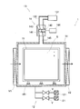
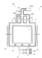
- FIG. 1 It is a schematic diagram which shows the film-forming apparatus. It is a typical sectional view showing the load lock room of this embodiment. It is typical sectional drawing which shows the conventional load lock chamber.
- the film forming apparatus I includes a plurality of vacuum chambers that perform predetermined processing on the substrate S.
- a load lock chamber 1 a heating chamber 2, and a film forming chamber 3 that are vertical vacuum apparatuses of the present invention are provided.
- a gate valve V ⁇ b> 1 is interposed on the upstream side of the load lock chamber 1.
- gate valves V2 and V3 are interposed between the load lock chamber 1, the heating chamber 2, and the film forming chamber 3, respectively, and the chambers are connected.
- the load lock chamber 1 is provided with a vacuum pump, and the load lock chamber 1 can be evacuated to a predetermined vacuum level to maintain the vacuum level. It is provided and configured to be able to break the vacuum in the load lock chamber 1.
- the heating chamber 2 is provided with a vacuum pump (not shown), and the inside of the heating chamber 2 can be evacuated to a predetermined degree of vacuum, and the degree of vacuum can be maintained.
- the heating chamber 2 is provided with a heating means (not shown) in the center thereof so that the temperature of the substrate S installed in the heating chamber 2 can be raised to a predetermined temperature.
- the film forming chamber 3 is provided with a vacuum pump (not shown), and the inside of the film forming chamber 3 can be evacuated to a predetermined vacuum level to maintain the vacuum level.
- the film forming chamber 3 is provided with a film forming means (not shown), and can form a film on the substrate S installed in the film forming chamber 3.
- the load lock chamber 1 includes a vacuum chamber 11.
- the volume of the vacuum chamber 11 in this embodiment is 1500 to 5000 L, which is suitable for processing a large substrate (for example, a substrate of 1.5 m ⁇ 1.5 m or more).
- the volume of the vacuum chamber 11 is 4000L.
- a gate valve V1 is provided on one side of the vacuum chamber 11, and a substrate is carried in from the gate valve V1.
- a gate valve V2 is also provided on the other side opposite to one side, and is connected to the heating chamber 2 (see FIG. 1) adjacent to the load lock chamber 1 by this gate valve V2.
- ribs are provided on the outer peripheral wall of the vacuum chamber 11 so as to suppress deformation of the vacuum chamber 11 in a vacuum state.
- the vacuum chamber 11 is provided with vacuum evacuation means 12 so that the inside of the vacuum chamber 11 can be evacuated.
- a vacuum exhaust pump 121 such as a turbo pump is provided in the vacuum chamber 11 via a valve V.
- the vacuum chamber 11 is provided with gas introduction means 13 for breaking the vacuum.
- the gas introduction means 13 includes a gas source 131 in which a low-reactivity vent gas such as nitrogen gas is sealed, and a gas pipe 132 connected to the gas source 131 at one end thereof. The other end of the gas pipe 132 is connected to the flow control valve 14.
- This flow control valve 14 also functions as a vacuum valve.
- the flow rate control valve 14 is provided with a valve portion 143 including a flow path 141 communicating with the gas pipe 132 and a valve body 142 that moves in the flow path 141 in parallel by driving a motor.
- the opening degree of the flow control valve 14 becomes 100%, and the opening degree of the flow control valve 14 gradually increases by projecting into the flow path 141 by driving the motor. Becomes narrower. And if the valve body 142 moves in the flow path 141 to such an extent that it contacts the surface facing the rest position, the opening degree of the flow control valve 14 becomes 0%.
- the flow rate control valve 14 includes a control unit 144 for controlling movement of the valve body 142 and a valve pipe 145 communicating with the flow path 141 outside the valve unit 143.
- the gas introduction pipe in the present invention includes the gas pipe 132 and the valve pipe 145 described above.
- the degree of opening and closing of the flow rate control valve can be freely controlled. That is, in the flow rate control valve 14, the vent gas from the gas source 131 is introduced into the vacuum chamber 11 through the gas pipe 132 and the flow rate control valve 14, and in this case, the vent gas flow rate is controlled by the control unit 144. It is introduced into the chamber 11.
- the flow rate control valve 14 also functions as a vacuum valve, the flow rate control valve 14 is provided close to the vacuum chamber 11 via only the valve pipe 145. Thereby, since it is not necessary to connect between the flow control valve 14 and the vacuum chamber 11 via another pipe, the air in the pipe or the vent gas remaining in the pipe at the start of the introduction of the vent gas is contained in the vacuum chamber 11. It can suppress that it introduce
- the operation of the film forming apparatus I and the load lock chamber 1 will be described below.
- the substrate S is carried into the film forming apparatus I while being held vertically or substantially perpendicular to the floor surface by the substrate holder 15.
- the substrate S is moved on the rail (not shown) provided across the load lock chamber 1, the heating chamber 2, and the film forming chamber 3 by the moving means 151 provided on the lower surface side of the substrate holder 15. After moving and loading from the load lock chamber 1 and moving to form a film in the film forming chamber 3, the film is transferred from the load lock chamber 1 to the outside again.
- the gate valve V1 is opened, and the substrate S is carried into the load lock chamber 1. Then, the load lock chamber 1 is evacuated by the evacuation means 12. When the load lock chamber 1 reaches a desired degree of vacuum, the gate valve V2 is opened to transfer the substrate S to the heating chamber 2. When the substrate S is heated to a desired temperature in the heating chamber 2, the gate valve V ⁇ b> 3 is then opened to transfer the substrate S to the film formation chamber 3. When the substrate S is deposited in the deposition chamber 3, the gate valve V ⁇ b> 3 is opened and the substrate S is carried out of the deposition chamber 3 to the heating chamber 2. Thereafter, the substrate S is carried into the load lock chamber 1 from the heating chamber 2.
- the load lock chamber 1A differs from the load lock chamber 1 shown in FIG. That is, the gas introduction means 13A provided in the load lock chamber 1A includes a gas source 131A and a common gas pipe 135 connected to the gas source 131A on one end side thereof. The other end of the common gas pipe 135 is divided into three gas pipes 136A, 136B, and 136C, which are connected to the vacuum chamber 11, respectively. That is, the vent gas introduced from the gas source 131A is introduced into the vacuum chamber 11 from the common gas pipe 135 through the individual gas pipes 136A, 136B, and 136C.
- the individual gas pipes 136A, 136B, and 136C are provided with openable and closable valves VA to VC to open and close the gas flow paths of the individual gas pipes 136A, 136B, and 136C.
- the vent gas when the vent gas is introduced, at the initial stage of introduction, only the narrowest individual gas pipe 136A among the individual gas pipes 136A, 136B, and 136C is opened to introduce the vent gas into the vacuum chamber 11. Thereafter, the valves VB and VC of the individual gas pipes 136B and 136C are opened, and the vent gas is introduced into the vacuum chamber 11.
- the vent gas is introduced only from the individual gas pipe 136A, the gas flow at the initial introduction of the vent gas is reduced, the pressure rise at the initial introduction is suppressed, and then the valves VB, VC of the individual gas pipes 136B and 136C are suppressed. Is opened and gas is introduced from all the individual gas pipes 136A, 136B, and 136C to increase the gas flow, thereby shortening the tact time.
- the substrate becomes larger and the thickness of the substrate becomes thinner, if the vacuum is broken in the load lock chamber 1A using such a gas introduction means 13A, the substrate is likely to crack as described above. Further, the particles may be wound up by the gas flow and adhere to the film formation surface.
- the opening degree of the flow control valve 14 is controlled by the control unit 144 so that the gas flow rate when the vent gas is introduced becomes a predetermined flow rate. Is introduced into the vacuum chamber 11 while controlling the flow rate. That is, the inventors of the present invention found that the cause of the adhesion of particles due to the cracking of the substrate and the rolling up of the particles is the pressure difference generated when switching the individual gas pipes for introducing the gas from the individual gas pipes 136A to all the individual gas pipes. Instead, it was clarified that this was due to the pressure difference when the vent gas was initially introduced, that is, when the vent gas was introduced only from the individual gas pipe 136A. And in order to control the pressure rise at the time of the initial introduction of the vent gas, the gas flow rate at the time of the initial introduction of the vent gas is controlled, so that the substrate is not cracked.
- the time of initial introduction means the time during which the inside of the vacuum chamber 11 changes from the molecular flow state to the viscous flow state due to the start of the introduction of the vent gas, and in this embodiment means within 1.5 seconds from the start of the introduction of the vent gas.
- the molecular flow state is a state where the atmospheric pressure is about 1 Pa or less and the gas is not yet viscous.
- the viscous flow state is a state where the pressure is 100 Pa or more and the gas molecules collide with the wall surface and the like. The state where the viscosity of is formed. During the transition from the molecular flow state to the viscous flow state, gas molecules collide with the wall surface and the like, and the viscosity of the gas is formed.
- the flow rate of the vent gas is controlled to suppress the substrate shaking and the generation of particles.
- the flow rate of the vent gas introduced into the load lock chamber 1 is controlled by controlling the flow rate of the vent gas.
- the controller 144 opens the valve so that the pressure Y (kPa) in the vacuum chamber 11 with respect to time X (seconds) satisfies Y ⁇ 0.3X + Z.
- Z is an initial pressure before the introduction of the vent gas in the vacuum chamber 11 and is determined by the specifications of the load lock chamber 1 and the performance of the vacuum pump used, and is 10 Pa (0.01 kPa) in this embodiment. If it is this range, the crack of a board
- the vent gas is introduced so that the pressure Y (kPa) in the vacuum chamber 11 with respect to time X (seconds) satisfies Y ⁇ 0.06X + 0.01. It is to be. If it is this range, the crack of a board
- the introduction of the vent gas only needs to be able to gradually increase the vent gas so that the pressure Y satisfies Y ⁇ 0.3X + Z at the initial introduction.
- the opening degree of the flow rate control valve 14 is adjusted so that the vent gas is continuously increased gradually to a maximum of 450 L / second after the initial introduction has elapsed. . That is, in this embodiment, as shown by a solid line in FIG.
- the flow rate control valve 14 is set so that the introduction speed of the vent gas becomes the first speed during the period from the introduction of the vent gas into the vacuum chamber 11 until the inside of the vacuum chamber 11 enters the molecular flow state.
- the vent gas is introduced by controlling the inside of the vacuum chamber 11 until the viscous flow state is reached after the inside of the vacuum chamber 11 is in a molecular flow state so that the introduction speed of the vent gas is a second speed higher than the first speed.
- a vent gas is introduced by controlling the flow control valve 14.
- the flow control valve 14 is provided in the vicinity of the vacuum chamber 11 via the valve pipe 145, so that the air in the pipe or the vent gas remaining in the pipe at the start of the introduction of the vent gas can be removed. Introducing into the vacuum chamber 11 can be suppressed. Thereby, while being able to control the flow volume of vent gas appropriately, it can suppress more that the board
- the point X of the substrate S shown in FIG. 2 is the laser displacement.
- a laser displacement meter was installed so as to be an observation point of a meter (manufactured by Keyence Corporation, product name LK500), and the vibration of the substrate S when vent gas was introduced as shown by the solid line in FIG. 4 was examined.
- a pressure measuring device (627 manufactured by MKS, 627D capacitance manometer) for measuring the pressure in the load lock chamber 1 was provided at the center of the chamber wall in the load lock chamber 1, and the change in pressure when the vent gas was introduced was examined. The results are shown in FIG.
- the pressure in the load lock chamber 1 is represented by a solid line
- the vibration of the substrate S is represented by a broken line.
- the vent gas when the vent gas is introduced as shown by the solid line in FIG. 4 in the film forming apparatus of this embodiment, that is, the pressure Y (kPa) in the vacuum chamber 11 with respect to time X (seconds) is the vent gas.
- the substrate S When introduced so that Y ⁇ 0.053X + 0.01 within 1.5 seconds from the introduction, the substrate S will not be greatly displaced at the time of initial introduction, thereby suppressing the cracking of the substrate S. It was.
- the results are shown in FIG. As shown in FIG. 6, the substrate did not crack between the introduction of the vent gas and the initial introduction time, but the substrate was vibrated, and thereafter there was no significant change even if the flow rate was changed greatly.
- a large vibration that may cause a crack of the substrate occurs between the introduction of the vent gas and the lapse of the initial introduction time.
- such a large vibration is generated. Vibration did not occur.
- the embodiment of the present invention is not limited to the above-described embodiment.
- the flow control valve 14 of the present embodiment is a motor-driven flow control valve.
- the flow control valve 14 is not limited to this.
- an electromagnetically driven valve that moves the valve electromagnetically by applying voltage control may be used. .
- the substrate holder 15 is shown as the substrate transfer means, but the substrate holder 15 is not limited to this as long as the substrate can be held substantially perpendicular to the floor surface.
- the vertical vacuum apparatus and processing method of the present invention can be used, for example, in the semiconductor manufacturing equipment industry.
Landscapes
- Chemical & Material Sciences (AREA)
- General Chemical & Material Sciences (AREA)
- Chemical Kinetics & Catalysis (AREA)
- Engineering & Computer Science (AREA)
- Materials Engineering (AREA)
- Mechanical Engineering (AREA)
- Metallurgy (AREA)
- Organic Chemistry (AREA)
- Physical Vapour Deposition (AREA)
- Chemical Vapour Deposition (AREA)
Abstract
縦型真空装置は、真空チャンバ11と、ベントガスを封入したガス源131と、ガス源及び真空チャンバに接続するガス導入管と、ガス導入管に設けられ、ガスの流量を制御するバルブとを備え、真空チャンバ内において基板が略垂直に保持された状態で、ガス源からベントガスを導入する縦型真空装置であって、バルブのバルブ開度を制御する制御手段144を有し、制御手段は、前記真空チャンバ内がベントガス導入開始により分子流状態から粘性流状態へと変化する間は、時間X(秒)に対する真空チャンバ11内の圧力Y(kPa)が、Y<0.3X+Z(Zは真空チャンバ内の初期圧力)となるようにバルブ開度を制御する。
Description
本発明は縦型真空装置及び処理方法に関する。
従来、半導体製造工程では、真空チャンバを複数備えた成膜装置を用いている。成膜装置は、スパッタリング法や蒸着法等により膜を形成するための成膜室の他に、ロードロック室を備える。ロードロック室は、成膜室内を真空に保持し大気に開放しないために、成膜処理前の基板を搬入し、または、成膜処理後の基板を外部へ搬出するために設置される。このため、ロードロック室は、ロードロック室内の状態を真空と大気とを繰り返させるべく、真空を形成するための真空排気手段と、真空状態にあるロードロック室内に真空を破壊するためのベントガスを導入するためのガス導入手段とを備えている。
このようなガス導入手段としては、例えば、真空状態の密閉容器内にガスを供給して大気圧にするスローベントバルブが知られている(例えば、特許文献1参照)。
特許文献1に記載したスローベントバルブは、リークバルブとガス供給源との間の配管にガス開閉弁が付設されており、このガス開閉弁を制御するガス開閉弁制御手段を備え、ガス供給によるパーティクルの発生を抑えているものである。しかしながら、スローベントバルブによりガスを供給する際に、供給されたガスのガス流により基板が振動して割れてしまうことがあるという問題がある。このような問題は、特に基板が大型化するにつれて基板が振動により割れやすくなるため、顕著になる問題である。
そこで、本発明の課題は、上記従来技術の問題点を解決することにあり、基板の割れを抑制した縦型真空装置及び処理方法を提供しようとするものである。
本発明の縦型真空装置は、真空チャンバと、ベントガスを封入したガス源と、該ガス源及び前記真空チャンバに接続するガス管と、ガス管に設けられ、ガスの流量を制御する流量制御バルブとを備え、前記真空チャンバ内において基板が略垂直に保持された状態で、前記ガス源から前記ベントガスを導入する縦型真空装置であって、前記流量制御バルブのバルブ開度を制御する制御手段を有し、該制御手段は、前記真空チャンバ内がベントガス導入開始により分子流状態から粘性流状態へと変化する間は、時間X(秒)に対する真空チャンバ内の圧力Y(kPa)が、Y<0.3X+Z(Zは真空チャンバ内の初期圧力)となるようにバルブ開度を制御することを特徴とする。
本発明においては、基板の割れが、ベントガス導入開始時から前記真空チャンバ内がベントガス導入開始により分子流状態から粘性流状態へと変化する間のベントガス導入によるものであることを見出し、これにより、バルブのバルブ開度を制御する制御手段が、前記真空チャンバ内がベントガス導入開始により分子流状態から粘性流状態へと変化する間は、時間Xに対する真空チャンバ内の圧力Y(kPa)が、Y<0.3X+Zとなるようにバルブ開度を制御することで、ベントガス導入初期時における基板の割れを抑制することができる。
ここで、前記流量制御バルブが、真空バルブとしても機能することが好ましい。このように構成することで、ベントガス導入初期時における基板の割れをより抑制することが可能である。
本発明の好ましい実施形態としては、前記真空チャンバの容積が、1500~5000Lであることが挙げられる。
本発明の処理方法は、真空チャンバと、ベントガスを封入したガス源と、該ガス源及び前記真空チャンバに接続するガス管と、ガス管に設けられ、ガスの流量を制御する流量制御バルブとを備えた縦型真空装置を用いて、前記真空チャンバ内において基板が略垂直に保持された状態でベントガスを導入して真空破壊を行う処理方法であって、前記真空チャンバ内がベントガス導入開始により分子流状態から粘性流状態へと変化する間は、時間X(秒)に対する真空チャンバ内の圧力Y(kPa)が、Y<0.3X+Z(Zは真空チャンバ内の初期圧力)となるようにバルブ開度を制御することを特徴とする。本発明においては、基板の割れがベントガス導入開始時からのベントガス導入によるものであることを見出し、これにより、バルブのバルブ開度を制御する制御手段が、前記真空チャンバ内がベントガス導入開始により分子流状態から粘性流状態へと変化する間は、時間Xに対する前記真空チャンバ内の圧力Yが、Y<0.3X+Zとなるようにバルブ開度を制御することで、ベントガス導入初期時における基板の割れを抑制することができる。
また、本発明の別の処理方法は、真空チャンバと、ベントガスを封入したガス源と、該ガス源及び前記真空チャンバに接続するガス導入管と、ガス導入管に設けられ、ガスの流量を制御する流量制御バルブとを備えた縦型真空装置を用いて、前記真空チャンバ内にベントガスを導入して真空破壊を行う処理方法であって、該真空チャンバ内に前記ベントガスを導入してから真空チャンバ内が分子流状態となるまでの間は、該ベントガスの導入速度が第1速度となるように前記流量制御バルブを制御してベントガスを導入し、真空チャンバ内が分子流状態となってから、粘性流状態となるまでの間は、ベントガスの導入速度を第1速度よりも早い第2速度となるように前記流量制御バルブを制御してベントガスを導入することを特徴とする。本発明においては、基板の割れがベントガス導入開始時からのベントガス導入によるものであることを見出し、これにより、該真空チャンバ内に前記ベントガスを導入してから真空チャンバ内が分子流状態となるまでの間は、該ベントガスの導入速度が第1速度となるように前記流量制御バルブを制御してベントガスを導入し、真空チャンバ内が分子流状態となってから、粘性流状態となるまでの間は、ベントガスの導入速度を第1速度よりも早い第2速度となるように前記流量制御バルブを制御してベントガスを導入することで、基板の割れを抑制することができる。
本発明の縦型真空装置及び処理方法によれば、ベントガス導入初期時における基板の割れを抑制することができるという優れた効果を奏し得る。
初めに、本発明の縦型真空装置を用いた成膜装置について図1を用いて説明する。
成膜装置Iは、基板Sに対して所定の処理を行う複数の真空チャンバを備える。本実施形態では、本発明の縦型真空装置であるロードロック室1と、加熱室2と、成膜室3とを備える。ロードロック室1の上流側には、ゲートバルブV1が介設されている。また、ロードロック室1と、加熱室2と、成膜室3との間にはそれぞれゲートバルブV2、V3が介設されて、各室は接続されている。
ロードロック室1は、詳しくは後述するが、真空ポンプが設けられ、ロードロック室1内を所定の真空度になるまで真空排気し、その真空度を保持することができると共に、ガス導入手段が設けられ、ロードロック室1内の真空を破壊することができるように構成されている。
加熱室2は、図示しない真空ポンプが設けられ、加熱室2内を所定の真空度になるまで真空排気し、その真空度を保持することができる。そして、加熱室2には、図示しない加熱手段がその中央部に設けられ、加熱室2内に設置された基板Sを所定の温度まで昇温できるように構成されている。
成膜室3は、図示しない真空ポンプが設けられ、成膜室3内を所定の真空度になるまで真空排気し、その真空度を保持することができる。そして、成膜室3には、図示しない成膜手段が設けられ、成膜室3内に設置された基板Sに対して成膜を行うことが可能である。
以下、本発明の縦型真空装置であるロードロック室1について図2を用いて詳細に説明する。
ロードロック室1は、真空チャンバ11を備える。本実施形態における真空チャンバ11の容積は、1500~5000Lであり、大型の基板(例えば、1.5m×1.5m以上の基板)の処理に適している。本実施形態では、真空チャンバ11の容積は、4000Lである。真空チャンバ11の一方側にはゲートバルブV1が設けられており、ゲートバルブV1から基板が搬入される。また、一方側に対向する他方側にもゲートバルブV2が設けられており、このゲートバルブV2により、ロードロック室1に隣接する加熱室2(図1参照)と接続されている。なお、図示しないが真空チャンバ11の外周壁にはリブを設けて真空状態時における真空チャンバ11の変形を抑制するように構成されている。真空チャンバ11には、真空排気手段12が設けられて、真空チャンバ11内を真空排気することができる。真空排気手段12としては、例えばターボポンプなどの真空排気ポンプ121がバルブVを介して真空チャンバ11に設けられている。
また、真空チャンバ11には、真空を破壊するためのガス導入手段13が設けられている。ガス導入手段13は、例えば窒素ガスなどの反応性の低いベントガスが封入されたガス源131と、ガス源131にその一端側で接続するガス管132とを有する。ガス管132は、その他端側が流量制御バルブ14に接続している。この流量制御バルブ14は、真空バルブとしても機能するものである。流量制御バルブ14には、ガス管132に連通する流路141と流路141内をモーター駆動により平行移動する弁体142とからなるバルブ部143が設けられている。弁体142が、流路141に臨む静止位置にあれば流量制御バルブ14の開度は100%となり、モーター駆動により流路141内に徐々に突出することで流量制御バルブ14の開度は徐々に狭くなる。そして、流路141内において、弁体142が、静止位置と対向する面に当接する程度まで移動すると、流量制御バルブ14の開度が0%となる。
また、流量制御バルブ14は、バルブ部143の外部に、弁体142を移動制御するための制御部144と、流路141と連通するバルブ管145を備える。なお、本発明におけるガス導入管とは、上述したガス管132と、このバルブ管145とからなる。弁体142の移動を制御部144により制御することで、流量制御バルブの開閉度を自在に制御することができる。即ち、流量制御バルブ14では、ガス源131からのベントガスは、ガス管132及び流量制御バルブ14を介して真空チャンバ11内に導入され、この場合に、制御部144によりベントガス流量が制御されて真空チャンバ11内に導入される。また、流量制御バルブ14は、真空バルブとしても機能するものであるので、バルブ管145のみを介して流量制御バルブ14が真空チャンバ11に近接して設けられている。これにより、流量制御バルブ14と真空チャンバ11との間を別の配管を介して接続しなくてよいので、ベントガス導入開始時に配管内の空気又は配管内に残ってしまったベントガスが真空チャンバ11内に導入されることを抑制できる。その結果、初期導入時における基板の振動やパーティクルの舞上がりを抑制することができる。なお、流量制御バルブ14と真空チャンバ11との間に開閉用の真空バルブを設ける場合には、制御バルブと開閉バルブとは0.5m以内となるように設けることが好ましい。
成膜装置I及びロードロック室1の作動について以下説明する。基板Sは、基板ホルダー15により床面に対して垂直又は略垂直に保持された状態で成膜装置I内に搬入される。基板Sは、基板ホルダー15の下面側に設けられた移動手段151により、成膜装置I内を、ロードロック室1、加熱室2、成膜室3に亘って設けられた図示しないレール上を移動し、ロードロック室1から搬入され、移動して成膜室3において成膜された後に、再度ロードロック室1から外部へ搬出される。
初めに、ゲートバルブV1が開き基板Sがロードロック室1に搬入される。そして、ロードロック室1が真空排気手段12により真空排気される。ロードロック室1が所望の真空度となると、ゲートバルブV2を開けて基板Sを加熱室2に搬送する。加熱室2において基板Sが所望の温度まで加熱されると、次いでゲートバルブV3を開けて基板Sを成膜室3に搬送する。そして、基板Sは成膜室3において成膜されると、ゲートバルブV3を開けて基板Sを成膜室3から加熱室2へ搬出する。その後、基板Sは、加熱室2からロードロック室1に搬入される。そして、加熱室2からロードロック室1に基板が搬入されると、ガス導入手段13からベントガスが導入されてロードロック室1の真空を破壊する。そして、ロードロック室1の圧力が大気と同一になった後にゲートバルブV1を開けて基板Sを搬出する。
ところで、従来は、このような基板を略垂直に保持した状態で真空チャンバ11内にベントガスを導入する真空破壊処理を行う場合、ガス導入時のガス流により基板が振動し、これにより基板に割れが発生してしまうことがあった。例えば、図3に示すような従来のロードロック室1Aにおいて真空を破壊する場合について説明する。
ロードロック室1Aは、図2に示すロードロック室1とは、ガス導入手段13の構成が異なる。即ち、ロードロック室1Aに設けられたガス導入手段13Aは、ガス源131Aと、ガス源131Aにその一端側で接続する共通ガス管135とを有する。共通ガス管135は、その他端側が個別ガス管136A、136B、136Cの3つに別れて、それぞれ真空チャンバ11に接続している。即ち、ガス源131Aから導入されたベントガスは、共通ガス管135から個別ガス管136A、136B、136Cを介して真空チャンバ11内に導入される。個別ガス管136A、136B、136Cには、開閉自在なバルブVA~VCが介設されていて、個別ガス管136A、136B、136Cのガス流路の開閉を行っている。
このロードロック室1Aにおいては、ベントガス導入時においては、導入初期時には、個別ガス管136A、136B、136Cのうち、最も細い個別ガス管136AのみバルブVAを開放してベントガスを真空チャンバ11内に導入し、その後、個別ガス管136B及び136CのバルブVB、VCを開放しベントガスを真空チャンバ11内に導入するように構成している。このように、初めは個別ガス管136Aのみからベントガスを導入しベントガスの初期導入時のガス流を小さくし、初期導入時の圧力上昇を抑えると共に、その後個別ガス管136B及び136CのバルブVB、VCを開放し全ての個別ガス管136A、136B、136Cからガスを導入してガス流を大きくすることで、タクトタイムの短縮化を図っていた。
しかしながら、基板が大型化、かつ、基板の厚さが薄くなるにつれて、このようなガス導入手段13Aを用いてロードロック室1Aにおいて真空を破壊すると、上述のように基板の割れが発生しやすく、また、ガス流によりパーティクルが巻き上げられて成膜面に付着してしまうことがあった。
そこで、本実施形態においては、基板Sの振動を抑制すると共に、パーティクルの巻き上げを抑制すべく、ベントガス導入時のガス流量を所定の流量となるように制御部144により流量制御バルブ14の開度を調整し流量を制御しながら真空チャンバ11内に導入している。即ち、本発明の発明者らは、基板の割れ及びパーティクルの巻き上げによるパーティクルの付着の原因は、ガスを導入する個別ガス管を個別ガス管136Aから全ての個別ガス管に切換える時に発生する圧力差ではなく、ベントガスの初期導入時、即ち個別ガス管136Aのみからのベントガスを導入する時における圧力差によるものであることを明らかにした。そして、ベントガス初期導入時の圧力上昇を制御すべく、このベントガスの初期導入時のガス流量を制御し、これにより、基板の割れが発生しないように構成しているのである。
ここで、初期導入時とは、真空チャンバ11内がベントガス導入開始により分子流状態から粘性流状態へと変化する間をいい、本実施形態では、ベントガス導入開始から1.5秒以内を意味する。分子流状態とは、気圧が約1Pa以下で、気体がまだ粘性を有していない状態をいい、粘性流状態とは、圧力が100Pa以上の状態で、気体分子が壁面に衝突などして気体の粘性が形成された状態をいう。分子流状態から粘性流状態になる間に、気体分子が壁面等に衝突して気体の粘性が形成されるが、この時には圧力差が生じやすく、この圧力差が、基板の揺れや、パーティクルの発生の原因となる。従って、本実施形態では、この分子流状態から粘性流状態となるまでの中間状態において、ベントガスの流量を制御して基板の揺れやパーティクルの発生を抑制している。
具体的には、本実施形態のロードロック室1においては、ベントガスの流量を制御してロードロック室1に導入されるベントガスの流量を制御する。制御部144は、初期導入時(本実施形態では1.5秒)は、時間X(秒)に対する真空チャンバ11内の圧力Y(kPa)が、Y<0.3X+Zを満たすように、バルブ開度を制御する。Zは、真空チャンバ11内のベントガス導入前における初期圧力であり、ロードロック室1の仕様や用いている真空ポンプの性能で決まるが、本実施形態では、10Pa(0.01kPa)である。この範囲であれば、基板の割れを防止でき、かつ、パーティクルの巻き上げも抑制できる。好ましくは、初期導入時(本実施形態では1.5秒)は、時間X(秒)に対する真空チャンバ11内の圧力Y(kPa)が、Y≦0.06X+0.01を満たすようにベントガスを導入することである。この範囲であれば、より確実に基板の割れを防止でき、かつ、パーティクルの巻き上げもより抑制できる。
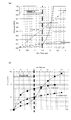
ここで、ベントガスの導入は、圧力Yが、初期導入時にはY<0.3X+Zを満たすように、ベントガスを連続的に漸増させることができればよい。例えば、図4に示す本実施形態では、実線で示すように、ベントガス導入開始から初期導入時(1.5秒)経過までは、1秒後までは17L/秒、1.5秒までは51L/秒となるようにベントガスを連続的に漸増させ、初期導入時経過後は、最大450L/秒となるようにベントガスを連続的に漸増させるように流量制御バルブ14の開度を調整している。即ち、本実施形態では、図4において実線で示すように、初期導入時には、時間X(秒)に対する真空チャンバ11内の圧力Y(kPa)が、Y≦0.053X+0.01を満たすように導入している。このように本実施形態においては、ベントガス導入開始から初期導入時間経過までの流量を制御することで、基板の割れやパーティクルの舞い上がりを抑制している。
即ち、本実施形態においては、真空チャンバ11内にベントガスを導入してから真空チャンバ11内が分子流状態となるまでの間は、ベントガスの導入速度が第1速度となるように流量制御バルブ14を制御してベントガスを導入し、真空チャンバ11内が分子流状態となってから、粘性流状態となるまでの間は、ベントガスの導入速度を第1速度よりも早い第2速度となるように流量制御バルブ14を制御してベントガスを導入している。これにより、ベントガス導入開始から初期導入時間経過までのガス流量を第1速度、第2速度として制御することで、基板の割れやパーティクルの舞い上がりを抑制している。
また、上述のように流量制御バルブ14は、バルブ管145を介して真空チャンバ11に近接して設けられていることで、ベントガス導入開始時に配管内の空気又は配管内に残ってしまったベントガスが真空チャンバ11内に導入されることを抑制できる。これにより、ベントガスの流量を適切に制御できると共に、ベントガス導入時に配管内の空気又はベントガスが導入されて基板が割れることをより抑制できる。
参考例として、以下、本実施形態のロードロック室1において、図2に示す基板Sの点X(ロードロック室床面からの距離が約4m、側面からの距離が約1m)が、レーザー変位計(キーエンス社製、商品名LK500)の観測点となるようにレーザー変位計を設置して、図4に実線で示すようにベントガスを導入した時の基板Sの振動を調べた。また、ロードロック室1内のチャンバ壁の中央にロードロック室1内の圧力を測定する圧力測定装置(MKS社製、627Dキャパシタンスマノメーター)を設け、このベントガス導入時の圧力変化を調べた。結果を図5に示す。図5中、ロードロック室1内の圧力は、実線で表し、基板Sの振動は破線で表している。図5によれば、本実施形態の成膜装置で、図4に実線で示すようにベントガスを導入した場合、即ち、時間X(秒)に対する真空チャンバ11内の圧力Y(kPa)が、ベントガス導入から1.5秒以内でY≦0.053X+0.01となるように導入した場合、初期導入時において基板Sが大きく変位することはなく、これにより、基板Sの割れを抑制することができた。
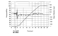
これに対し、図3に示すロードロック室1Aにおいて、本実施形態の点Xと同一の位置に位置する点Yが観測点になるように同一の条件でレーザー変位計を設置して即ち、時間X(秒)に対する真空チャンバ11内の圧力Y(kPa)が、ベントガス導入から1.5秒以内でY=0.3X+0.01となるようにベントガスを導入して基板の振動を調べた。結果を図6に示す。図6に示すように、ベントガス導入から初期導入時間経過までの間に、基板は割れなかったが振動が発生し、その後は流量を大きく変えても大きな変化はなかった。
このように、従来のロードロック室1Aにおいては、ベントガス導入から初期導入時間経過までの間に基板の割れの原因ともなりうる大きな振動が発生しているが、本実施形態では、このような大きな振動は発生しなかった。
(他の実施形態)
本発明の実施形態は、上述した実施形態に限定されない。例えば、本実施形態の流量制御バルブ14は、モーター駆動の流量制御バルブであったが、これに限定されず、例えば印加電圧制御により電磁的にバルブを移動させる電磁駆動のバルブを用いてもよい。
本発明の実施形態は、上述した実施形態に限定されない。例えば、本実施形態の流量制御バルブ14は、モーター駆動の流量制御バルブであったが、これに限定されず、例えば印加電圧制御により電磁的にバルブを移動させる電磁駆動のバルブを用いてもよい。
また、本実施形態では、基板の搬送手段として基板ホルダー15を示したが、基板を床面に対して略垂直に保持することができれば、これに限定されない。
本発明の縦型真空装置及び処理方法は、例えば半導体製造装置産業において利用可能である。
1 ロードロック室
11 真空チャンバ
12 真空排気手段
13 ガス導入手段
14 流量制御バルブ
15 基板ホルダー
121 真空排気ポンプ
131 ガス源
132 ガス管
141 流路
142 弁体
143 バルブ部
144 制御部
145 バルブ管
151 移動手段
S 基板
11 真空チャンバ
12 真空排気手段
13 ガス導入手段
14 流量制御バルブ
15 基板ホルダー
121 真空排気ポンプ
131 ガス源
132 ガス管
141 流路
142 弁体
143 バルブ部
144 制御部
145 バルブ管
151 移動手段
S 基板
Claims (5)
- 真空チャンバと、ベントガスを封入したガス源と、該ガス源及び前記真空チャンバに接続するガス導入管と、ガス導入管に設けられ、ガスの流量を制御する流量制御バルブとを備え、
前記真空チャンバ内において基板が略垂直に保持された状態で、前記ガス源から前記ベントガスを導入する縦型真空装置であって、
前記流量制御バルブのバルブ開度を制御する制御手段を有し、
該制御手段は、前記真空チャンバ内がベントガス導入開始により分子流状態から粘性流状態へと変化する間は、時間X(秒)に対する真空チャンバ内の圧力Y(kPa)が、Y<0.3X+Z(Zは真空チャンバ内の初期圧力)となるようにバルブ開度を制御することを特徴とする縦型真空装置。 - 前記流量制御バルブが、真空バルブとしても機能することを特徴とする請求項1記載の縦型真空装置。
- 前記真空チャンバの容積が、1500~5000Lであることを特徴とする請求項1又は2記載の縦型真空装置。
- 真空チャンバと、ベントガスを封入したガス源と、該ガス源及び前記真空チャンバに接続するガス導入管と、ガス導入管に設けられ、ガスの流量を制御する流量制御バルブとを備えた縦型真空装置を用いて、前記真空チャンバ内において基板が略垂直に保持された状態でベントガスを導入して真空破壊を行う処理方法であって、
前記真空チャンバ内がベントガス導入開始により分子流状態から粘性流状態へと変化する間は、時間X(秒)に対する真空チャンバ内の圧力Y(kPa)が、Y<0.3X+Z(Zは真空チャンバ内の初期圧力)となるようにバルブ開度を制御することを特徴とする処理方法。 - 真空チャンバと、ベントガスを封入したガス源と、該ガス源及び前記真空チャンバに接続するガス導入管と、ガス導入管に設けられ、ガスの流量を制御する流量制御バルブとを備えた真空装置を用いて、前記真空チャンバ内にベントガスを導入して真空破壊を行う処理方法であって、
該真空チャンバ内に前記ベントガスを導入してから真空チャンバ内が分子流状態となるまでの間は、該ベントガスの導入速度が第1速度となるように前記流量制御バルブを制御してベントガスを導入し、
真空チャンバ内が分子流状態となってから、粘性流状態となるまでの間は、ベントガスの導入速度を第1速度よりも早い第2速度となるように前記流量制御バルブを制御してベントガスを導入することを特徴とする処理方法。
Applications Claiming Priority (2)
| Application Number | Priority Date | Filing Date | Title |
|---|---|---|---|
| JP2010034099 | 2010-02-18 | ||
| JP2010-034099 | 2010-02-18 |
Publications (1)
| Publication Number | Publication Date |
|---|---|
| WO2011102405A1 true WO2011102405A1 (ja) | 2011-08-25 |
Family
ID=44482991
Family Applications (1)
| Application Number | Title | Priority Date | Filing Date |
|---|---|---|---|
| PCT/JP2011/053340 Ceased WO2011102405A1 (ja) | 2010-02-18 | 2011-02-17 | 縦型真空装置及び処理方法 |
Country Status (2)
| Country | Link |
|---|---|
| TW (1) | TW201202462A (ja) |
| WO (1) | WO2011102405A1 (ja) |
Cited By (2)
| Publication number | Priority date | Publication date | Assignee | Title |
|---|---|---|---|---|
| JPWO2013099178A1 (ja) * | 2011-12-27 | 2015-04-30 | シャープ株式会社 | ロードロック装置及びそれを備えた真空処理装置 |
| WO2019037235A1 (zh) * | 2017-08-22 | 2019-02-28 | 武汉华星光电半导体显示技术有限公司 | 一种蒸发源装置 |
Citations (4)
| Publication number | Priority date | Publication date | Assignee | Title |
|---|---|---|---|---|
| JPS59133365A (ja) * | 1983-11-28 | 1984-07-31 | Hitachi Ltd | 真空装置 |
| JPH06101782A (ja) * | 1992-09-17 | 1994-04-12 | Ckd Corp | バイパス弁付真空排気用開閉弁 |
| JPH06158360A (ja) * | 1992-11-20 | 1994-06-07 | Tokyo Electron Ltd | 真空処理装置 |
| JP2009030720A (ja) * | 2007-07-26 | 2009-02-12 | Tadashi Kamimura | ベントバルブ |
-
2011
- 2011-02-17 WO PCT/JP2011/053340 patent/WO2011102405A1/ja not_active Ceased
- 2011-02-18 TW TW100105417A patent/TW201202462A/zh unknown
Patent Citations (4)
| Publication number | Priority date | Publication date | Assignee | Title |
|---|---|---|---|---|
| JPS59133365A (ja) * | 1983-11-28 | 1984-07-31 | Hitachi Ltd | 真空装置 |
| JPH06101782A (ja) * | 1992-09-17 | 1994-04-12 | Ckd Corp | バイパス弁付真空排気用開閉弁 |
| JPH06158360A (ja) * | 1992-11-20 | 1994-06-07 | Tokyo Electron Ltd | 真空処理装置 |
| JP2009030720A (ja) * | 2007-07-26 | 2009-02-12 | Tadashi Kamimura | ベントバルブ |
Cited By (2)
| Publication number | Priority date | Publication date | Assignee | Title |
|---|---|---|---|---|
| JPWO2013099178A1 (ja) * | 2011-12-27 | 2015-04-30 | シャープ株式会社 | ロードロック装置及びそれを備えた真空処理装置 |
| WO2019037235A1 (zh) * | 2017-08-22 | 2019-02-28 | 武汉华星光电半导体显示技术有限公司 | 一种蒸发源装置 |
Also Published As
| Publication number | Publication date |
|---|---|
| TW201202462A (en) | 2012-01-16 |
Similar Documents
| Publication | Publication Date | Title |
|---|---|---|
| US9447926B2 (en) | Plasma process method | |
| JP5371238B2 (ja) | プラズマ処理装置およびプラズマ処理方法 | |
| CN105304526B (zh) | 基板处理装置和基板处理方法 | |
| TWI438822B (zh) | 常溫接合裝置及常溫接合方法 | |
| KR101572091B1 (ko) | 기판 처리 장치 및 반도체 장치의 제조 방법 | |
| CN105374705B (zh) | 衬底处理装置、半导体器件的制造方法及记录介质 | |
| KR101669752B1 (ko) | 기판 처리 장치, 반도체 장치의 제조 방법 및 기록 매체 | |
| RU2727634C1 (ru) | Устройство для осаждения или очистки с подвижной конструкцией и способ его эксплуатации | |
| KR102186773B1 (ko) | 플라스마 처리 장치 및 플라스마 처리 방법 | |
| KR20150111812A (ko) | 기판 처리 장치, 반도체 장치의 제조 방법 및 기록 매체 | |
| CN103311149B (zh) | 用于半导体制造工具的阀净化组件 | |
| JP2016046450A (ja) | プラズマ処理装置 | |
| KR20100031460A (ko) | Ti계 막의 성막 방법 및 기억 매체 | |
| KR102070313B1 (ko) | 반도체 장치의 제조 방법, 기판 처리 장치 및 기록 매체 | |
| US20220068637A1 (en) | Film-forming method, film-forming apparatus, and oxidation method | |
| CN104112636B (zh) | 真空装置和阀控制方法 | |
| TWI608119B (zh) | 原子層沉積設備及其抽氣速率控制方法 | |
| TW201202462A (en) | Vertical vacuum device and processing method | |
| CN108573861A (zh) | 半导体器件的制造方法、衬底处理装置及记录介质 | |
| JP4490008B2 (ja) | 真空処理装置及び真空処理方法 | |
| US7972961B2 (en) | Purge step-controlled sequence of processing semiconductor wafers | |
| WO2024069763A1 (ja) | 基板処理方法、半導体装置の製造方法、基板処理装置、及びプログラム | |
| JP2010202912A (ja) | 原子層成長装置および方法 | |
| JP2010272551A (ja) | 基板処理装置及び基板処理方法 | |
| JP2018085399A (ja) | 成膜装置および成膜方法 |
Legal Events
| Date | Code | Title | Description |
|---|---|---|---|
| 121 | Ep: the epo has been informed by wipo that ep was designated in this application |
Ref document number: 11744691 Country of ref document: EP Kind code of ref document: A1 |
|
| NENP | Non-entry into the national phase |
Ref country code: DE |
|
| 122 | Ep: pct application non-entry in european phase |
Ref document number: 11744691 Country of ref document: EP Kind code of ref document: A1 |
|
| NENP | Non-entry into the national phase |
Ref country code: JP |