WO2011096396A1 - 脱気装置 - Google Patents
脱気装置 Download PDFInfo
- Publication number
- WO2011096396A1 WO2011096396A1 PCT/JP2011/052039 JP2011052039W WO2011096396A1 WO 2011096396 A1 WO2011096396 A1 WO 2011096396A1 JP 2011052039 W JP2011052039 W JP 2011052039W WO 2011096396 A1 WO2011096396 A1 WO 2011096396A1
- Authority
- WO
- WIPO (PCT)
- Prior art keywords
- deaeration
- chamber
- rotor
- outlet
- space
- Prior art date
- Legal status (The legal status is an assumption and is not a legal conclusion. Google has not performed a legal analysis and makes no representation as to the accuracy of the status listed.)
- Ceased
Links
Images





Classifications
-
- B—PERFORMING OPERATIONS; TRANSPORTING
- B29—WORKING OF PLASTICS; WORKING OF SUBSTANCES IN A PLASTIC STATE IN GENERAL
- B29B—PREPARATION OR PRETREATMENT OF THE MATERIAL TO BE SHAPED; MAKING GRANULES OR PREFORMS; RECOVERY OF PLASTICS OR OTHER CONSTITUENTS OF WASTE MATERIAL CONTAINING PLASTICS
- B29B7/00—Mixing; Kneading
- B29B7/80—Component parts, details or accessories; Auxiliary operations
- B29B7/84—Venting or degassing ; Removing liquids, e.g. by evaporating components
-
- B—PERFORMING OPERATIONS; TRANSPORTING
- B29—WORKING OF PLASTICS; WORKING OF SUBSTANCES IN A PLASTIC STATE IN GENERAL
- B29B—PREPARATION OR PRETREATMENT OF THE MATERIAL TO BE SHAPED; MAKING GRANULES OR PREFORMS; RECOVERY OF PLASTICS OR OTHER CONSTITUENTS OF WASTE MATERIAL CONTAINING PLASTICS
- B29B7/00—Mixing; Kneading
- B29B7/80—Component parts, details or accessories; Auxiliary operations
- B29B7/84—Venting or degassing ; Removing liquids, e.g. by evaporating components
- B29B7/845—Venting, degassing or removing evaporated components in devices with rotary stirrers
- B29B7/847—Removing of gaseous components before or after mixing
-
- B—PERFORMING OPERATIONS; TRANSPORTING
- B01—PHYSICAL OR CHEMICAL PROCESSES OR APPARATUS IN GENERAL
- B01D—SEPARATION
- B01D19/00—Degasification of liquids
- B01D19/0036—Flash degasification
-
- B—PERFORMING OPERATIONS; TRANSPORTING
- B29—WORKING OF PLASTICS; WORKING OF SUBSTANCES IN A PLASTIC STATE IN GENERAL
- B29C—SHAPING OR JOINING OF PLASTICS; SHAPING OF MATERIAL IN A PLASTIC STATE, NOT OTHERWISE PROVIDED FOR; AFTER-TREATMENT OF THE SHAPED PRODUCTS, e.g. REPAIRING
- B29C48/00—Extrusion moulding, i.e. expressing the moulding material through a die or nozzle which imparts the desired form; Apparatus therefor
- B29C48/25—Component parts, details or accessories; Auxiliary operations
- B29C48/36—Means for plasticising or homogenising the moulding material or forcing it through the nozzle or die
- B29C48/395—Means for plasticising or homogenising the moulding material or forcing it through the nozzle or die using screws surrounded by a cooperating barrel, e.g. single screw extruders
-
- B—PERFORMING OPERATIONS; TRANSPORTING
- B29—WORKING OF PLASTICS; WORKING OF SUBSTANCES IN A PLASTIC STATE IN GENERAL
- B29C—SHAPING OR JOINING OF PLASTICS; SHAPING OF MATERIAL IN A PLASTIC STATE, NOT OTHERWISE PROVIDED FOR; AFTER-TREATMENT OF THE SHAPED PRODUCTS, e.g. REPAIRING
- B29C48/00—Extrusion moulding, i.e. expressing the moulding material through a die or nozzle which imparts the desired form; Apparatus therefor
- B29C48/25—Component parts, details or accessories; Auxiliary operations
- B29C48/36—Means for plasticising or homogenising the moulding material or forcing it through the nozzle or die
- B29C48/50—Details of extruders
- B29C48/505—Screws
- B29C48/57—Screws provided with kneading disc-like elements, e.g. with oval-shaped elements
-
- B—PERFORMING OPERATIONS; TRANSPORTING
- B29—WORKING OF PLASTICS; WORKING OF SUBSTANCES IN A PLASTIC STATE IN GENERAL
- B29C—SHAPING OR JOINING OF PLASTICS; SHAPING OF MATERIAL IN A PLASTIC STATE, NOT OTHERWISE PROVIDED FOR; AFTER-TREATMENT OF THE SHAPED PRODUCTS, e.g. REPAIRING
- B29C48/00—Extrusion moulding, i.e. expressing the moulding material through a die or nozzle which imparts the desired form; Apparatus therefor
- B29C48/25—Component parts, details or accessories; Auxiliary operations
- B29C48/36—Means for plasticising or homogenising the moulding material or forcing it through the nozzle or die
- B29C48/50—Details of extruders
- B29C48/76—Venting, drying means; Degassing means
-
- B—PERFORMING OPERATIONS; TRANSPORTING
- B29—WORKING OF PLASTICS; WORKING OF SUBSTANCES IN A PLASTIC STATE IN GENERAL
- B29C—SHAPING OR JOINING OF PLASTICS; SHAPING OF MATERIAL IN A PLASTIC STATE, NOT OTHERWISE PROVIDED FOR; AFTER-TREATMENT OF THE SHAPED PRODUCTS, e.g. REPAIRING
- B29C48/00—Extrusion moulding, i.e. expressing the moulding material through a die or nozzle which imparts the desired form; Apparatus therefor
- B29C48/25—Component parts, details or accessories; Auxiliary operations
- B29C48/36—Means for plasticising or homogenising the moulding material or forcing it through the nozzle or die
- B29C48/50—Details of extruders
- B29C48/76—Venting, drying means; Degassing means
- B29C48/765—Venting, drying means; Degassing means in the extruder apparatus
-
- B—PERFORMING OPERATIONS; TRANSPORTING
- B29—WORKING OF PLASTICS; WORKING OF SUBSTANCES IN A PLASTIC STATE IN GENERAL
- B29C—SHAPING OR JOINING OF PLASTICS; SHAPING OF MATERIAL IN A PLASTIC STATE, NOT OTHERWISE PROVIDED FOR; AFTER-TREATMENT OF THE SHAPED PRODUCTS, e.g. REPAIRING
- B29C48/00—Extrusion moulding, i.e. expressing the moulding material through a die or nozzle which imparts the desired form; Apparatus therefor
- B29C48/03—Extrusion moulding, i.e. expressing the moulding material through a die or nozzle which imparts the desired form; Apparatus therefor characterised by the shape of the extruded material at extrusion
Definitions
- the present invention relates to a deaeration device.
- a semiconductor package in which a semiconductor chip (semiconductor element) is covered (sealed) with a resin sealing material is known.
- the sealing material of this semiconductor package is a resin composition formed by, for example, transfer molding or the like, and if the resin composition is insufficiently degassed, voids are generated in the sealing material. There is.
- Patent Document 1 provides a decompression vent port (a deaeration chamber) communicating with the interior of a twin-screw kneading extruder. Is depressurized to deaerate the resin composition.
- a method of providing a deaeration chamber in the middle of two kneading extruders has been proposed.
- the inlet of the degassing chamber is connected to the outlet of the first kneading extruder, and the inlet of the second kneading extruder is connected to the outlet of the degassing chamber.
- the material kneaded by the first kneading extruder is deaerated in the deaeration chamber and then kneaded by the second kneading extruder.
- the degassing chamber can be decompressed by sealing the inlet side of the degassing chamber with the material in the first kneading extruder and sealing the outlet side of the degassing chamber with the material in the second kneading extruder. It has become.
- An object of the present invention is to provide a deaeration device that can easily and reliably deaerate the kneaded material.
- the present invention includes an inlet for introducing a kneaded material, a deaeration chamber for degassing the material, and an outlet for discharging the degassed material.
- a housing having Decompression means for decompressing the deaeration chamber; Sealing means for sealing between the outlet and the deaeration chamber; In a sealed state where the outlet and the deaeration chamber are sealed by the sealing unit, the deaeration chamber is depressurized by the depressurization unit to a depressurized state, and the material in the deaeration chamber is reduced.
- a degassing apparatus configured to perform degassing.
- the housing has a cylindrical portion that is provided between the inlet and the outlet, and forms a cylindrical shape.
- the sealing means includes a rotor that is rotatably installed in the cylindrical portion and has a plurality of partition plates that partition the cylindrical portion into a plurality of spaces; It is preferable that the material is conveyed to the outlet by the partition plate when the rotor rotates.
- the deaeration chamber is provided between the inlet and the cylindrical part.
- the decompression means has a conduit communicating with the deaeration chamber,
- the deaeration chamber has the plurality of spaces, It is preferable that each space is rotated by the rotation of the rotor, and the space communicating with the pipeline among the spaces is decompressed via the pipeline.
- the space has a non-communication state in which the space does not communicate with the inlet and the outlet, and the deaeration is performed in the non-communication state.
- a gap having a gap distance of 0.2 mm or less is formed between the inner peripheral surface of the cylindrical portion and the tip of the partition plate.
- At least the surface of the rotor is made of a non-metal.
- At least the inner peripheral surface of the cylindrical portion is made of a non-metal.
- the residence time of the material in the degassing apparatus is preferably 1 minute or less.
- the pressure in the deaeration chamber during the deaeration is set to 60 kPa or less.
- the inlet is preferably connected to the outlet of the kneading apparatus.
- FIG. 1 is a diagram illustrating a production process of a resin composition.
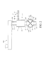
- FIG. 2 is a cross-sectional view showing a first embodiment of the deaeration device of the present invention.
- FIG. 3 is a cross-sectional view showing a second embodiment of the deaeration device of the present invention.
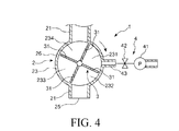
- 4 is a cross-sectional view of the deaeration device shown in FIG.
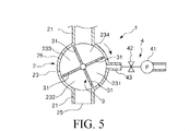
- FIG. 5 is a cross-sectional view of the deaeration device shown in FIG.
- FIG. 6 is a cross-sectional view showing a third embodiment of the deaeration device of the present invention.
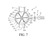
- FIG. 7 is a cross-sectional view of the deaeration device shown in FIG.
- FIG. 8 is a cross-sectional view of the deaeration device shown in FIG. FIG.
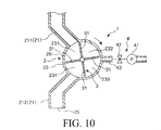
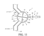
- FIG. 9 is a cross-sectional view showing a fourth embodiment of the deaeration device of the present invention. 10 is a cross-sectional view of the deaeration device shown in FIG. FIG. 11 is a cross-sectional view of the deaeration device shown in FIG.
- FIG. 1 is a view showing a manufacturing process of a resin composition
- FIG. 2 is a cross-sectional view showing a first embodiment of a deaeration device of the present invention.
- the upper side in FIG. 2 is “upper (upstream)”, the lower side is “lower (downstream)”, the left side is “left”, and the right side is “right”.
- a deaeration apparatus 1 shown in FIG. 2 is an apparatus used in a deaeration process when a resin composition that is a molded body (a green compact) is manufactured. Prior to the description of the deaeration device 1, first, the entire manufacturing process until the resin composition is manufactured from the raw materials will be described.
- each material which is a raw material of a resin composition is prepared.
- the raw material includes a resin, a curing agent, and a filler (fine particles), and further includes a curing accelerator and a coupling agent as necessary.
- the resin an epoxy resin is preferable.
- epoxy resin examples include a cresol novolac type, a biphenyl type, a dicyclopentadiene type, a triphenolmethane type, and a polyaromatic ring type.
- Examples of the curing agent include a phenol novolac type, a phenol aralkyl type, a triphenolmethane type, and a polyaromatic ring type.
- Examples of the filler include fused silica (crushed and spherical), crystalline silica, alumina, and the like.
- Examples of the curing accelerator include phosphorus compounds and amine compounds.
- Examples of the coupling agent include silane compounds.
- the predetermined material may be abbreviate
- examples of other materials include a colorant, a release agent, a low stress agent, and a flame retardant.
- Examples of the flame retardant include brominated epoxy resin, antimony oxide, and non-halo / non-antimony type.
- Examples of the non-halo / non-antimony flame retardant include organic phosphorus, metal hydrate, nitrogen-containing resin, and the like.
- a predetermined material of raw materials is first pulverized (finely pulverized) with a pulverizer so as to have a predetermined particle size distribution.
- the raw material to be crushed is, for example, a raw material other than a filler such as a resin, a curing agent, and a curing accelerator, but a part of the filler can also be added.
- a crusher a continuous rotation ball mill etc. can be used, for example.
- a predetermined material of the raw materials, for example, all or a part (remainder) of the filler can be subjected to a surface treatment.
- a surface treatment for example, a coupling agent or the like is attached to the surface of the filler.
- the fine pulverization and the surface treatment may be performed at the same time, or one of them may be performed first.
- mixing device Next, the respective materials are thoroughly mixed by a mixing device.
- a mixing apparatus for example, a high-speed mixer having rotating blades can be used.
- the mixed material is kneaded by the kneading apparatus 100.
- this kneading apparatus 100 for example, an extrusion kneader such as a single-screw kneading extruder, a biaxial kneading extruder, or a roll kneader such as a mixing roll can be used.
- the degassing apparatus 1 performs degassing on the kneaded material.
- the deaeration device 1 will be described in detail later.
- the degassed bulk material is formed into a sheet shape by a sheet forming apparatus to obtain a sheet-like material.
- a sheeting roll or the like can be used as the sheet forming apparatus.
- the sheet material is pulverized by a pulverizer so as to have a predetermined particle size distribution, thereby obtaining a powder material.
- a pulverizer for example, a hammer mill or the like can be used.
- a die having a small diameter is installed at the outlet of the kneader and discharged from the die without going through the sheeting, cooling, and pulverization steps described above.
- a hot cut method of obtaining a granular resin composition by cutting the molten resin composition to a predetermined length with a cutter or the like can also be used. In this case, after obtaining the granular resin composition by the hot cut method, it is preferable to perform deaeration before the temperature of the resin composition is lowered so much.
- the powdered material can be compression-molded by a molded body manufacturing apparatus (tablet apparatus) to obtain a resin composition that is a molded body.
- This fat composition is used for covering (sealing) a semiconductor chip (semiconductor element), for example. That is, the resin composition is molded, for example, by transfer molding, and a semiconductor chip is covered as a sealing material to manufacture a semiconductor package.
- the tableting step may be omitted and a powdered material may be used as the resin composition.
- the sealing material can be formed by compression molding, injection molding, or the like.
- the deaeration device 1 As shown in FIG. 2, the deaeration device 1 is used by being connected to the discharge port 101 of the kneading device 100.
- the deaeration device 1 includes a housing 2, a rotor (sealing means) 3 rotatably installed in the housing 2, and a decompression mechanism (decompression means) 4 that decompresses a later-described deaeration chamber 22 of the housing 2.
- the housing 2 includes a pipe 21, a degassing chamber 22 provided in the middle of the pipe 21, for degassing the material kneaded by the kneading apparatus 100, and a cylindrical portion (cylindrical). 23.
- the cylindrical portion 23 is located below the deaeration chamber 22.
- the upper end of the pipe 21 constitutes an inlet 24 into which the material kneaded by the kneading apparatus 100 is introduced, and the lower end constitutes an outlet 25 from which the degassed material is discharged. To do.
- the deaeration chamber 22 is provided between the inlet 24 and the cylindrical portion 23, and in the configuration shown in the figure, the cross section has a cylindrical shape that forms a quadrangle. Moreover, the area in the cross section in the deaeration chamber 22 is set larger than the area in the cross section in the pipe 21. Needless to say, the area in the cross section in the deaeration chamber 22 and the area in the cross section in the duct 21 may be set equal.
- the cylindrical part 23 is provided between the deaeration chamber 22 (inlet 24) and the outlet 25, and in the configuration shown in the figure, it is cylindrical and has a shape in which both ends thereof are closed.
- the rotor 3 is installed so that it can rotate clockwise in FIG.
- the rotor 3 seals between the outlet 25 and the deaeration chamber 22.
- the deaeration chamber 22 can be decompressed easily and reliably.
- the inlet 24 side of the housing 2 is sealed with the kneaded material in the kneading apparatus 100 located near the inlet 24.
- the rotor 3 has a plurality of (four in the illustrated configuration) partition plates 31 that partition the inside of the cylindrical portion 23 into a plurality of spaces (four spaces 231, 232, 233, and 234 in the illustrated configuration).
- the partition plates 31 are arranged at equal intervals (equal angular intervals), that is, at 90 ° intervals in the illustrated configuration.
- the rotor 3 is rotated by the operation of a motor (drive source) (not shown). Then, when the rotor 3 rotates, the material is conveyed to the outlet 25 by the partition plate 31.
- a gap is formed between the inner peripheral surface of the cylindrical portion 23 and the tip of the partition plate 31.
- the tip of the partition plate 31 may be rounded (R-treated (chamfered)).
- the radius of curvature (R) of the tip of the partition plate 31 is preferably 0.2 mm or more and 2 mm or less, more preferably 0.2 mm or more and 1 mm or less. If the radius of curvature is too large, the material adheres to the tip of the partition plate 31 and the inner peripheral surface of the cylindrical portion 23, which is not preferable for work.
- the size of the gap that is, the gap distance between the inner peripheral surface of the cylindrical portion 23 and the tip of the partition plate 31 is preferably 0.2 mm or less, and is about 0.01 to 0.1 mm. It is more preferable. Thereby, it can prevent that the partition plate 31 rubs the cylindrical part 23, preventing a leak.
- the partition plate 31 and the cylindrical part 23 can be cooled. By cooling, adhesion of material can be suppressed and deaeration work can be carried out with lubrication.
- the constituent material of the housing 2 is not particularly limited, but at least the inner peripheral surface of the cylindrical portion 23 is preferably made of a non-metal, and at least the inner peripheral surface of the housing 2 is made of a non-metal. It is more preferable. In this case, you may comprise the whole cylindrical part 23 with a nonmetal. Moreover, you may comprise the whole housing 2 with a nonmetal.
- the constituent material of the rotor 3 is not particularly limited, but at least the surface of the rotor 3 is preferably made of a non-metal. In this case, you may comprise the whole rotor 3 with a nonmetal.
- the metal content increase amount in the material after deaeration by the deaerator 1 can be 1.0 wtppm or less, particularly 0.1 wtppm or less.
- the non-metallic material is not particularly limited, and examples thereof include ceramic materials and resin materials such as alumina and zirconia. Among these, ceramic materials are preferable.
- the decompression mechanism 4 includes a pipe line 43 connected to the deaeration chamber 22 (communicating with the deaeration room 22), a pump 41 for decompressing the inside of the deaeration room 22 via the pipe line 43, and the deaeration room 22. And a valve 42 installed between the pump 41 and the pump 41.
- the valve 42 When degassing the material, the valve 42 is opened, the pump 41 is operated, and the inside of the degassing chamber 22 is depressurized.
- the degree of vacuum (degree of vacuum) at the time of deaeration that is, the pressure (atmospheric pressure) in the deaeration chamber 22 is not particularly limited, but is preferably set to 60 kPa or less, and set to 50 kPa or less. Is more preferable, and it is more preferable to set the pressure to about 30 to 50 kPa. Thereby, deaeration can be performed more reliably.
- action of the deaeration apparatus 1 in a deaeration process is demonstrated.
- the housing 2 of the deaeration device 1 is in a sealed state in which the space between the outlet 25 and the deaeration chamber 22 is sealed by the partition plate 31 of the rotor 3 in the cylindrical portion 23.
- the valve 42 of the deaeration apparatus 1 When the material kneaded by the kneading apparatus 100 is deaerated, the valve 42 of the deaeration apparatus 1 is opened, the pump 41 is operated, the inside of the deaeration chamber 22 is decompressed to a decompressed state, The motor which is not operated is operated to rotate the rotor 3.
- the inside of the deaeration chamber 22 is depressurized, not only the inside of the deaeration chamber 22 but also the inside of the duct 21 above the deaeration chamber 22 is depressurized to be in a depressurized state.
- the space 231 partitioned by the partition plate 31 in the pipe line 21 and in the cylindrical portion 23 communicating with the pipe line 21 is also decompressed to be in a decompressed state.
- the material kneaded by the kneading apparatus 100 is discharged from the discharge port 101 of the kneading apparatus 100 and introduced (supplied) to the degassing apparatus 1 from the inlet 24 of the degassing apparatus 1.
- the material moves downward due to its own weight (gravity), passes through the conduit 21, the deaeration chamber 22, and the conduit 21, and communicates with the conduit 21 (deaeration chamber 22). 23, and is deaerated while the space 231 communicates with the conduit 21.
- gas for example, air etc.
- the material in the space 231 is conveyed to the outlet 25 by the partition plate 31 by the rotation of the rotor 3, and is discharged from the outlet 25.
- the residence time of the material in the deaerator 1 is preferably 1 minute or less, more preferably about 3 to 30 seconds, and further preferably about 5 to 15 seconds.
- the residence time By setting the residence time to be equal to or less than the above upper limit value, it is possible to prevent the deterioration of the material characteristics due to the thermal history, and it is possible to suppress the cooling of the discharged material and to prevent the sheet formation in the next process. Moreover, deaeration can be more reliably performed by making residence time more than the said lower limit.
- the residence time is the time from when the material is supplied from the inlet 24 of the degassing device 1 to when the material is discharged from the outlet 25 of the degassing device 1.
- This residence time can be freely adjusted by controlling the drive of the rotor 3.
- the dwell time can be set to the target value by setting the rotation speed (rotation speed) of the rotor 3 to a predetermined value.
- the residence time can also be set to the target value by stopping the rotor 3 in the middle for a predetermined time. Specific examples include the following method 1 and method 2.
- the rotor 3 is continuously rotated, and the rotational speed of the rotor 3 is set to a predetermined value.
- the rotational speed of the rotor 3 is preferably set to a value in the range of about 1 to 10 rpm, and more preferably set to a value in the range of about 2 to 6 rpm.
- the rotor 3 is intermittently rotated by a predetermined angle, and the stop time of the rotor 3 per rotation operation is set to a predetermined value.
- the stop time of the rotor 3 is appropriately set according to various conditions such as the rotation speed of the rotor 3, the rotation angle of the rotor 3 per one rotation operation, the number of partition plates 31, and the like. It is preferably set to a value in the range of about seconds, and more preferably set to a value in the range of about 1 to 15 seconds.
- the rotation speed of the rotor 3 is appropriately set according to various conditions such as the stop time of the rotor 3, the rotation angle of the rotor 3 per one rotation operation, the number of the partition plates 31, and the like, but about 1 to 13 rpm. Is preferably set to a value within a range of about 2 to 8 rpm.
- the rotation angle of the rotor 3 per one rotation operation is appropriately set according to various conditions such as the number of the partition plates 31 and is preferably set to about 45 to 120 °, for example, 90 More preferably, the angle is set to about 120 °.
- the rotation angle of the rotor 3 per one rotation operation is set to 360 / N (°). In this case, in the illustrated configuration, since the number of the partition plates 31 is four, the rotation angle of the rotor 3 per one rotation operation is set to 90 °.
- the kneaded material can be reliably deaerated. Thereby, when a semiconductor chip is sealed using the manufactured resin composition, generation of voids can be prevented and the reliability of the semiconductor package can be improved.
- FIG. 3 is a cross-sectional view showing a second embodiment of the deaerator of the present invention
- FIGS. 4 and 5 are cross-sectional views of the deaerator shown in FIG. 3, respectively.
- the upper side in FIGS. 3 to 5 is described as “upper (upstream)”, the lower side is “lower (downstream)”, the left side is “left”, and the right side is “right”.
- a deaeration chamber 26 is configured by the cylindrical portion 23 and the rotor 3. That is, the four spaces 231 to 234 in the cylindrical portion 23 constitute the space of the deaeration chamber 26, respectively.
- conduit 43 of the decompression mechanism 4 is connected to the cylindrical portion 23, that is, the right side of the deaeration chamber 26 (communicated in the deaeration chamber 26).
- the rotation of the rotor 3 causes the spaces 231 to 234 to rotate, and the space (the space 232 in FIG. 3) communicating with the pipeline 43 among the spaces 231 to 234 is decompressed via the pipeline 43. It is comprised so that it may be in a pressure reduction state.
- the kneaded material introduced into the deaeration device 1 from the inlet 24 of the deaeration device 1 moves downward due to its own weight, and passes through the pipeline 21. It passes through and is accommodated in a space 231 in the cylindrical portion 23 that communicates with the pipeline 21.
- the state shown in FIG. 4 to the state shown in FIG. 5 is a non-communication state in which the space 231 is not communicated with the inlet 24 and the outlet 25.
- the material stored in the space 231 Is degassed. According to this deaeration device 1, the same effect as the first embodiment described above can be obtained.
- FIG. 6 is a cross-sectional view showing a third embodiment of the deaeration device of the present invention
- FIGS. 7 and 8 are cross-sectional views of the deaeration device shown in FIG. 6, respectively.
- the upper side in FIGS. 6 to 8 is described as “upper (upstream)”, the lower side is “lower (downstream)”, the left side is “left”, and the right side is “right”.
- the number of partition plates 31 of the rotor 3 is set to be larger than that of the second embodiment. That is, the rotor 3 has six partition plates 31 that partition the inside of the cylindrical portion 23 into six spaces 231, 232, 233, 234, 235, and 236, and each of the six spaces 231 to 236 is deaerated. A space of the chamber 26 is configured.
- the space 232 in FIG. 6 communicates with the pipe line 43, the space 232 does not communicate with the inlet 24 and the outlet 25. That is, when the space 232 communicates with the inlet 24 and when it communicates with the outlet 25, the space 232 does not communicate with the conduit 43.
- FIG. 9 is a sectional view showing a fourth embodiment of the deaeration device of the present invention
- FIGS. 10 and 11 are sectional views of the deaeration device shown in FIG. 9, respectively.
- the upper side in FIGS. 9 to 11 is described as “upper (upstream)”, the lower side is “lower (downstream)”, the left side is “left”, and the right side is “right”.
- the pipe line 21 is bent or curved, and the upper pipe line 211 is shifted to the left side from right above the cylindrical part 23. It is connected to the position (communication), and the lower pipe line 212 is connected to a position shifted to the left side from directly below the cylindrical portion 23.
- the pipeline 211, the pipeline 212, and the pipeline 43 are arranged at equal intervals (equal angular intervals), that is, at intervals of 120 ° in the illustrated configuration.
- the space 232 when the space (the space 232 in FIG. 9) communicates with the pipe line 43, the space 232 does not communicate with the inlet 24 and the outlet 25. That is, when the space 232 communicates with the inlet 24 and when it communicates with the outlet 25, the space 232 does not communicate with the conduit 43.
- the present invention may be a combination of any two or more configurations (features) of the above embodiments.
- the sealing means since the sealing means is provided, the kneaded material can be easily and reliably deaerated without adversely affecting the processing of the kneading apparatus. Therefore, it has industrial applicability.
Landscapes
- Engineering & Computer Science (AREA)
- Mechanical Engineering (AREA)
- Chemical & Material Sciences (AREA)
- Chemical Kinetics & Catalysis (AREA)
- Processing And Handling Of Plastics And Other Materials For Molding In General (AREA)
- Degasification And Air Bubble Elimination (AREA)
- Extrusion Moulding Of Plastics Or The Like (AREA)
- Centrifugal Separators (AREA)
Abstract
Description
前記脱気室を減圧する減圧手段と、
前記出口と前記脱気室との間を封止する封止手段とを備え、
前記封止手段により前記出口と前記脱気室との間を封止した封止状態で、前記減圧手段により前記脱気室を減圧して減圧状態とし、前記脱気室内の前記材料に対して脱気を行うよう構成されていることを特徴とする脱気装置である。
前記封止手段は、前記筒状部内に回転自在に設置され、前記筒状部内を複数の空間に仕切る複数の仕切板を有するロータを備え、
前記ロータが回転することにより、前記仕切板により前記材料が前記出口へ搬送されるよう構成されているのが好ましい。
前記脱気室は、前記複数の空間を有しており、
前記ロータの回転により、前記各空間が回転し、前記各空間のうち、前記管路に連通した前記空間が前記管路を介して減圧されるよう構成されているのが好ましい。
<第1実施形態>
図1は、樹脂組成物の製造工程を示す図、図2は、本発明の脱気装置の第1実施形態を示す断面図である。
原材料は、樹脂と、硬化剤と、充填材(微粒子)とを有し、さらに必要を応じて、硬化促進剤と、カップリング剤等を有している。樹脂としては、エポキシ樹脂が好ましい。
カップリング剤としては、例えば、シラン化合物等が挙げられる。
図1に示すように、原材料のうちの所定の材料については、まず、粉砕装置により、所定の粒度分布となるように粉砕(微粉砕)する。この粉砕する原材料としては、例えば、樹脂、硬化剤、硬化促進剤等の充填材以外の原材料であるが、充填材の一部を加えることもできる。また、粉砕装置としては、例えば、連続式回転ボールミル等を用いることができる。
原材料のうちの所定の材料、例えば、充填材の全部または一部(残部)については、表面処理を施すことができる。この表面処理としては、例えば、充填材の表面にカップリング剤等を付着させる。なお、前記微粉砕と表面処理とは、同時に行ってもよく、また、いずれか一方を先に行ってもよい。
次に、混合装置により、前記各材料を完全に混合する。この混合装置としては、例えば、回転羽根を有する高速混合機等を用いることができる。
次に、混練装置100により、前記混合された材料を混練する。この混練装置100としては、例えば、1軸型混練押出機、2軸型混練押出機等の押出混練機やミキシングロール等のロール式混練機を用いることができる。
次に、脱気装置1により、前記混練された材料に対し脱気を行う。なお、脱気装置1については、後に詳述する。
次に、シート化装置により、前記脱気した塊状の材料をシート状に成形し、シート状の材料を得る。このシート化装置としては、例えば、シーティングロール等を用いることができる。
次に、冷却装置により、前記シート状の材料を冷却する。これにより、材料の粉砕を容易かつ確実に行うことができる。
次に、粉砕装置により、シート状の材料を所定の粒度分布となるように粉砕し、粉末状の材料を得る。この粉砕装置としては、例えば、ハンマーミル等を用いることができる。
次に、成形体製造装置(打錠装置)により、前記粉末状の材料を圧縮成形し、成形体である樹脂組成物を得ることができる。
図2に示すように、脱気装置1は、混練装置100の排出口101に接続されて用いられる。
これにより、より確実に脱気を行うことができる。
前述したように、脱気装置1のハウジング2は、筒状部23においてロータ3の仕切板31により出口25と脱気室22との間が封止された封止状態となっている。
ロータ3を連続的に回転させ、そのロータ3の回転速度を所定値に設定する。この場合、ロータ3の回転速度は、1~10rpm程度の範囲内の値に設定されることが好ましく、2~6rpm程度の範囲内の値に設定されることがより好ましい。
ロータ3を所定角度ずつ間欠的に回転させ、1回の回転動作当たりそのロータ3の停止時間を所定値に設定する。この場合、ロータ3の停止時間は、ロータ3の回転速度、1回の回転動作当たりのロータ3の回転角度、仕切板31の数等の諸条件に応じて適宜設定されるが、1~60秒程度の範囲内の値に設定されることが好ましく、1~15秒程度の範囲内の値に設定されることがより好ましい。
図3は、本発明の脱気装置の第2実施形態を示す断面図、図4および図5は、それぞれ、図3に示す脱気装置の断面図である。なお、以下では、図3~図5中の上側を「上(上流)」、下側を「下(下流)」、左側を「左」、右側を「右」として説明を行う。
この脱気装置1によれば、前述した第1実施形態と同様の効果が得られる。
図6は、本発明の脱気装置の第3実施形態を示す断面図、図7および図8は、それぞれ、図6に示す脱気装置の断面図である。なお、以下では、図6~図8中の上側を「上(上流)」、下側を「下(下流)」、左側を「左」、右側を「右」として説明を行う。
この脱気装置1によれば、前述した第2実施形態と同様の効果が得られる。
図9は、本発明の脱気装置の第4実施形態を示す断面図、図10および図11は、それぞれ、図9に示す脱気装置の断面図である。なお、以下では、図9~図11中の上側を「上(上流)」、下側を「下(下流)」、左側を「左」、右側を「右」として説明を行う。
この脱気装置1によれば、前述した第2実施形態と同様の効果が得られる。
Claims (12)
- 混練された材料が導入される入口と、前記材料に対して脱気を行う脱気室と、脱気された前記材料が排出される出口とを有するハウジングと、
前記脱気室を減圧する減圧手段と、
前記出口と前記脱気室との間を封止する封止手段とを備え、
前記封止手段により前記出口と前記脱気室との間を封止した封止状態で、前記減圧手段により前記脱気室を減圧して減圧状態とし、前記脱気室内の前記材料に対して脱気を行うよう構成されていることを特徴とする脱気装置。 - 前記ハウジングは、前記入口と前記出口との間に設けられた筒状をなす筒状部を有し、
前記封止手段は、前記筒状部内に回転自在に設置され、前記筒状部内を複数の空間に仕切る複数の仕切板を有するロータを備え、
前記ロータが回転することにより、前記仕切板により前記材料が前記出口へ搬送されるよう構成されている請求項1に記載の脱気装置。 - 前記脱気室は、前記入口と前記筒状部との間に設けられている請求項2に記載の脱気装置。
- 前記減圧手段は、前記脱気室に連通する管路を有し、
前記脱気室は、前記複数の空間を有しており、
前記ロータの回転により、前記各空間が回転し、前記各空間のうち、前記管路に連通した前記空間が前記管路を介して減圧されるよう構成されている請求項2に記載の脱気装置。 - 前記空間が前記入口および前記出口に連通していない非連通状態があり、該非連通状態のとき、前記脱気を行うよう構成されている請求項4に記載の脱気装置。
- 前記筒状部の内周面と前記仕切板の先端との間に、間隙距離が0.2mm以下の隙間が形成されている請求項2ないし5のいずれかに記載の脱気装置。
- 前記ロータの少なくとも表面は、非金属で構成されている請求項2ないし6のいずれかに記載の脱気装置。
- 前記筒状部の少なくとも内周面は、非金属で構成されている請求項2ないし7のいずれかに記載の脱気装置。
- 当該脱気装置における前記材料の滞留時間は、1分以下である請求項1ないし8のいずれかに記載の脱気装置。
- 前記脱気の際の前記脱気室内の圧力は、60kPa以下に設定される請求項1ないし9のいずれかに記載の脱気装置。
- 前記入口は、混練装置の排出口に接続される請求項1ないし10のいずれかに記載の脱気装置。
- 前記材料は、樹脂と微粒子とを含む請求項1ないし11のいずれかに記載の脱気装置。
Priority Applications (4)
| Application Number | Priority Date | Filing Date | Title |
|---|---|---|---|
| KR1020127018621A KR101809763B1 (ko) | 2010-02-05 | 2011-02-01 | 탈기장치 |
| SG2012055620A SG182755A1 (en) | 2010-02-05 | 2011-02-01 | Degassing apparatus |
| CN201180006221.4A CN102712106B (zh) | 2010-02-05 | 2011-02-01 | 脱气装置 |
| US13/574,841 US8906147B2 (en) | 2010-02-05 | 2011-02-01 | Degassing apparatus |
Applications Claiming Priority (2)
| Application Number | Priority Date | Filing Date | Title |
|---|---|---|---|
| JP2010-023944 | 2010-02-05 | ||
| JP2010023944A JP5671807B2 (ja) | 2010-02-05 | 2010-02-05 | 脱気装置 |
Publications (1)
| Publication Number | Publication Date |
|---|---|
| WO2011096396A1 true WO2011096396A1 (ja) | 2011-08-11 |
Family
ID=44355394
Family Applications (1)
| Application Number | Title | Priority Date | Filing Date |
|---|---|---|---|
| PCT/JP2011/052039 Ceased WO2011096396A1 (ja) | 2010-02-05 | 2011-02-01 | 脱気装置 |
Country Status (8)
| Country | Link |
|---|---|
| US (1) | US8906147B2 (ja) |
| JP (1) | JP5671807B2 (ja) |
| KR (1) | KR101809763B1 (ja) |
| CN (1) | CN102712106B (ja) |
| MY (1) | MY162990A (ja) |
| SG (1) | SG182755A1 (ja) |
| TW (1) | TWI540034B (ja) |
| WO (1) | WO2011096396A1 (ja) |
Cited By (1)
| Publication number | Priority date | Publication date | Assignee | Title |
|---|---|---|---|---|
| CN110355947A (zh) * | 2019-07-26 | 2019-10-22 | 长沙秋点兵信息科技有限公司 | 一种注塑模具 |
Citations (8)
| Publication number | Priority date | Publication date | Assignee | Title |
|---|---|---|---|---|
| JPH06190891A (ja) * | 1992-08-31 | 1994-07-12 | Hiroshi Morohashi | 可塑化装置及びこの装置を用いた可塑化方法 |
| JPH06226816A (ja) * | 1993-02-05 | 1994-08-16 | Japan Steel Works Ltd:The | 溶融脱気押出成形方法及び装置 |
| JPH09290421A (ja) * | 1996-04-26 | 1997-11-11 | Sumitomo Bakelite Co Ltd | 半導体封止用エポキシ樹脂組成物の製造方法 |
| JPH10180839A (ja) * | 1996-12-26 | 1998-07-07 | Sumitomo Bakelite Co Ltd | 押出ダイ及びそれを用いた半導体封止用エポキシ樹脂組成物の製造方法 |
| JP2006123449A (ja) * | 2004-11-01 | 2006-05-18 | Yashima Kensetsu Kk | 廃複合樹脂ペレット製造装置及びその製造方法 |
| JP2007031768A (ja) * | 2005-07-26 | 2007-02-08 | Nippon Steel Corp | 含鉄粉体の押出成形方法 |
| JP2007190905A (ja) * | 2005-12-19 | 2007-08-02 | Hitachi Chem Co Ltd | 混合装置、混合物および半導体装置 |
| JP2009528930A (ja) * | 2006-03-07 | 2009-08-13 | トータル・ペトロケミカルズ・リサーチ・フエリユイ | ポリマー粉末の脱気装置および方法 |
Family Cites Families (10)
| Publication number | Priority date | Publication date | Assignee | Title |
|---|---|---|---|---|
| US1614526A (en) * | 1924-12-30 | 1927-01-18 | James M Lambie | Method of and apparatus for forming articles of plastic material |
| US2306265A (en) * | 1941-04-17 | 1942-12-22 | Colgate Palmolive Peet Co | Degasifying viscous compositions |
| US2774105A (en) * | 1954-04-27 | 1956-12-18 | Du Pont | Extraction-extrusion apparatus |
| BE564132A (ja) * | 1957-01-22 | 1900-01-01 | ||
| US3371379A (en) * | 1965-01-02 | 1968-03-05 | Reifenhauser K G | Apparatus for degassing thermoplastic material in screw presses |
| JPH0815732B2 (ja) * | 1986-09-10 | 1996-02-21 | 電気化学工業株式会社 | 混練物の連続脱泡注型装置 |
| KR100280928B1 (ko) * | 1992-08-31 | 2001-04-02 | 히로시 모로하시 | 가소화 장치 및 이 장치를 이용한 가소화 방법 |
| ATE166950T1 (de) * | 1992-10-28 | 1998-06-15 | Maag Pump Systems Ag | Verfahren und stufe zur behandlung einer thermoplastschmelze mit einer zahnradpumpe |
| JPH08332616A (ja) * | 1995-06-08 | 1996-12-17 | Ikuyo Tekkosho:Goushi | 窯業製品素地の押出成形装置および窯業製品素地表面への不定形模様形成用の押出成形装置 |
| JP4295869B2 (ja) | 1999-09-14 | 2009-07-15 | 日東電工株式会社 | 半導体封止用エポキシ樹脂組成物の製法 |
-
2010
- 2010-02-05 JP JP2010023944A patent/JP5671807B2/ja active Active
-
2011
- 2011-02-01 SG SG2012055620A patent/SG182755A1/en unknown
- 2011-02-01 US US13/574,841 patent/US8906147B2/en active Active
- 2011-02-01 KR KR1020127018621A patent/KR101809763B1/ko active Active
- 2011-02-01 CN CN201180006221.4A patent/CN102712106B/zh active Active
- 2011-02-01 MY MYPI2012003348A patent/MY162990A/en unknown
- 2011-02-01 WO PCT/JP2011/052039 patent/WO2011096396A1/ja not_active Ceased
- 2011-02-08 TW TW100104099A patent/TWI540034B/zh active
Patent Citations (8)
| Publication number | Priority date | Publication date | Assignee | Title |
|---|---|---|---|---|
| JPH06190891A (ja) * | 1992-08-31 | 1994-07-12 | Hiroshi Morohashi | 可塑化装置及びこの装置を用いた可塑化方法 |
| JPH06226816A (ja) * | 1993-02-05 | 1994-08-16 | Japan Steel Works Ltd:The | 溶融脱気押出成形方法及び装置 |
| JPH09290421A (ja) * | 1996-04-26 | 1997-11-11 | Sumitomo Bakelite Co Ltd | 半導体封止用エポキシ樹脂組成物の製造方法 |
| JPH10180839A (ja) * | 1996-12-26 | 1998-07-07 | Sumitomo Bakelite Co Ltd | 押出ダイ及びそれを用いた半導体封止用エポキシ樹脂組成物の製造方法 |
| JP2006123449A (ja) * | 2004-11-01 | 2006-05-18 | Yashima Kensetsu Kk | 廃複合樹脂ペレット製造装置及びその製造方法 |
| JP2007031768A (ja) * | 2005-07-26 | 2007-02-08 | Nippon Steel Corp | 含鉄粉体の押出成形方法 |
| JP2007190905A (ja) * | 2005-12-19 | 2007-08-02 | Hitachi Chem Co Ltd | 混合装置、混合物および半導体装置 |
| JP2009528930A (ja) * | 2006-03-07 | 2009-08-13 | トータル・ペトロケミカルズ・リサーチ・フエリユイ | ポリマー粉末の脱気装置および方法 |
Cited By (2)
| Publication number | Priority date | Publication date | Assignee | Title |
|---|---|---|---|---|
| CN110355947A (zh) * | 2019-07-26 | 2019-10-22 | 长沙秋点兵信息科技有限公司 | 一种注塑模具 |
| CN110355947B (zh) * | 2019-07-26 | 2021-09-07 | 衢州市东晟日用品有限公司 | 一种用于注塑模具的挤出装置 |
Also Published As
| Publication number | Publication date |
|---|---|
| JP5671807B2 (ja) | 2015-02-18 |
| MY162990A (en) | 2017-07-31 |
| TW201200323A (en) | 2012-01-01 |
| JP2011161318A (ja) | 2011-08-25 |
| CN102712106B (zh) | 2015-04-08 |
| US8906147B2 (en) | 2014-12-09 |
| CN102712106A (zh) | 2012-10-03 |
| KR20120112581A (ko) | 2012-10-11 |
| KR101809763B1 (ko) | 2017-12-15 |
| US20120291631A1 (en) | 2012-11-22 |
| SG182755A1 (en) | 2012-08-30 |
| TWI540034B (zh) | 2016-07-01 |
Similar Documents
| Publication | Publication Date | Title |
|---|---|---|
| CN102762347B (zh) | 粉碎装置及粉碎方法 | |
| JP5593741B2 (ja) | 冷却装置および冷却方法 | |
| JP5636719B2 (ja) | 成形体製造装置および成形体の製造方法 | |
| CN102753260A (zh) | 粒子制造装置、粒子制造方法及半导体封装用树脂组合物的制造方法 | |
| TWI503165B (zh) | 混練裝置及半導體密封用樹脂組成物之製造方法 | |
| KR101832514B1 (ko) | 성형장치 및 성형방법 | |
| JP5671807B2 (ja) | 脱気装置 | |
| EP2537890A1 (en) | Manufacturing method for resin composition containing fine paper powder |
Legal Events
| Date | Code | Title | Description |
|---|---|---|---|
| WWE | Wipo information: entry into national phase |
Ref document number: 201180006221.4 Country of ref document: CN |
|
| 121 | Ep: the epo has been informed by wipo that ep was designated in this application |
Ref document number: 11739744 Country of ref document: EP Kind code of ref document: A1 |
|
| ENP | Entry into the national phase |
Ref document number: 20127018621 Country of ref document: KR Kind code of ref document: A |
|
| WWE | Wipo information: entry into national phase |
Ref document number: 13574841 Country of ref document: US |
|
| WWE | Wipo information: entry into national phase |
Ref document number: 1201003555 Country of ref document: TH |
|
| NENP | Non-entry into the national phase |
Ref country code: DE |
|
| 122 | Ep: pct application non-entry in european phase |
Ref document number: 11739744 Country of ref document: EP Kind code of ref document: A1 |