WO2011090107A1 - 画像処理装置、撮像装置、プログラム及び画像処理方法 - Google Patents
画像処理装置、撮像装置、プログラム及び画像処理方法 Download PDFInfo
- Publication number
- WO2011090107A1 WO2011090107A1 PCT/JP2011/050948 JP2011050948W WO2011090107A1 WO 2011090107 A1 WO2011090107 A1 WO 2011090107A1 JP 2011050948 W JP2011050948 W JP 2011050948W WO 2011090107 A1 WO2011090107 A1 WO 2011090107A1
- Authority
- WO
- WIPO (PCT)
- Prior art keywords
- light receiving
- value
- unit
- pixel value
- light
- Prior art date
Links
- 238000003384 imaging method Methods 0.000 title claims abstract description 34
- 238000003672 processing method Methods 0.000 title claims abstract description 6
- 238000000034 method Methods 0.000 claims description 163
- 238000004364 calculation method Methods 0.000 claims description 62
- 230000006870 function Effects 0.000 claims description 45
- 238000011156 evaluation Methods 0.000 claims description 42
- 230000008569 process Effects 0.000 claims description 27
- 238000013528 artificial neural network Methods 0.000 claims description 16
- 238000003860 storage Methods 0.000 claims description 14
- 230000035945 sensitivity Effects 0.000 claims description 3
- 238000010586 diagram Methods 0.000 description 41
- 238000005070 sampling Methods 0.000 description 17
- 230000004927 fusion Effects 0.000 description 9
- 230000008859 change Effects 0.000 description 8
- 230000003287 optical effect Effects 0.000 description 8
- 238000001514 detection method Methods 0.000 description 6
- 238000009826 distribution Methods 0.000 description 6
- 230000000052 comparative effect Effects 0.000 description 4
- 238000012986 modification Methods 0.000 description 4
- 230000004048 modification Effects 0.000 description 4
- 238000007476 Maximum Likelihood Methods 0.000 description 2
- 230000003044 adaptive effect Effects 0.000 description 2
- 230000006866 deterioration Effects 0.000 description 2
- 230000000694 effects Effects 0.000 description 2
- 230000002093 peripheral effect Effects 0.000 description 2
- 230000009467 reduction Effects 0.000 description 2
- 230000002194 synthesizing effect Effects 0.000 description 2
- NAWXUBYGYWOOIX-SFHVURJKSA-N (2s)-2-[[4-[2-(2,4-diaminoquinazolin-6-yl)ethyl]benzoyl]amino]-4-methylidenepentanedioic acid Chemical compound C1=CC2=NC(N)=NC(N)=C2C=C1CCC1=CC=C(C(=O)N[C@@H](CC(=C)C(O)=O)C(O)=O)C=C1 NAWXUBYGYWOOIX-SFHVURJKSA-N 0.000 description 1
- 238000013144 data compression Methods 0.000 description 1
- 238000009795 derivation Methods 0.000 description 1
- 230000002542 deteriorative effect Effects 0.000 description 1
- 238000001914 filtration Methods 0.000 description 1
- 230000017525 heat dissipation Effects 0.000 description 1
- 230000007246 mechanism Effects 0.000 description 1
- 238000004091 panning Methods 0.000 description 1
- 238000012887 quadratic function Methods 0.000 description 1
- 238000011946 reduction process Methods 0.000 description 1
- 230000003252 repetitive effect Effects 0.000 description 1
- 239000007787 solid Substances 0.000 description 1
- 230000002123 temporal effect Effects 0.000 description 1
Images


Classifications
-
- G—PHYSICS
- G06—COMPUTING; CALCULATING OR COUNTING
- G06T—IMAGE DATA PROCESSING OR GENERATION, IN GENERAL
- G06T3/00—Geometric image transformations in the plane of the image
- G06T3/40—Scaling of whole images or parts thereof, e.g. expanding or contracting
- G06T3/4053—Scaling of whole images or parts thereof, e.g. expanding or contracting based on super-resolution, i.e. the output image resolution being higher than the sensor resolution
- G06T3/4069—Scaling of whole images or parts thereof, e.g. expanding or contracting based on super-resolution, i.e. the output image resolution being higher than the sensor resolution by subpixel displacements
-
- H—ELECTRICITY
- H04—ELECTRIC COMMUNICATION TECHNIQUE
- H04N—PICTORIAL COMMUNICATION, e.g. TELEVISION
- H04N25/00—Circuitry of solid-state image sensors [SSIS]; Control thereof
- H04N25/40—Extracting pixel data from image sensors by controlling scanning circuits, e.g. by modifying the number of pixels sampled or to be sampled
- H04N25/46—Extracting pixel data from image sensors by controlling scanning circuits, e.g. by modifying the number of pixels sampled or to be sampled by combining or binning pixels
-
- H—ELECTRICITY
- H04—ELECTRIC COMMUNICATION TECHNIQUE
- H04N—PICTORIAL COMMUNICATION, e.g. TELEVISION
- H04N23/00—Cameras or camera modules comprising electronic image sensors; Control thereof
- H04N23/60—Control of cameras or camera modules
- H04N23/667—Camera operation mode switching, e.g. between still and video, sport and normal or high- and low-resolution modes
-
- H—ELECTRICITY
- H04—ELECTRIC COMMUNICATION TECHNIQUE
- H04N—PICTORIAL COMMUNICATION, e.g. TELEVISION
- H04N23/00—Cameras or camera modules comprising electronic image sensors; Control thereof
- H04N23/95—Computational photography systems, e.g. light-field imaging systems
- H04N23/951—Computational photography systems, e.g. light-field imaging systems by using two or more images to influence resolution, frame rate or aspect ratio
-
- H—ELECTRICITY
- H04—ELECTRIC COMMUNICATION TECHNIQUE
- H04N—PICTORIAL COMMUNICATION, e.g. TELEVISION
- H04N25/00—Circuitry of solid-state image sensors [SSIS]; Control thereof
- H04N25/48—Increasing resolution by shifting the sensor relative to the scene
-
- H—ELECTRICITY
- H04—ELECTRIC COMMUNICATION TECHNIQUE
- H04N—PICTORIAL COMMUNICATION, e.g. TELEVISION
- H04N25/00—Circuitry of solid-state image sensors [SSIS]; Control thereof
- H04N25/60—Noise processing, e.g. detecting, correcting, reducing or removing noise
-
- H—ELECTRICITY
- H04—ELECTRIC COMMUNICATION TECHNIQUE
- H04N—PICTORIAL COMMUNICATION, e.g. TELEVISION
- H04N7/00—Television systems
- H04N7/015—High-definition television systems
- H04N7/0152—High-definition television systems using spatial or temporal subsampling
- H04N7/0155—High-definition television systems using spatial or temporal subsampling using pixel blocks
Definitions
- the present invention relates to an image processing device, an imaging device, a program, an image processing method, and the like.
- Some modern digital cameras and video cameras can be used by switching between still image shooting mode and movie shooting mode. For example, there is a camera that can shoot a still image with a resolution higher than that of a moving image by a user operating a button during moving image shooting.
- the method of switching between the still image shooting mode and the moving image shooting mode has a problem that when the user notices a photo opportunity, a decisive moment is often missed already.
- Patent Documents 1 and 2 disclose a method of synthesizing a high resolution image from a low resolution image acquired by pixel shift.
- the methods of Patent Documents 1 and 2 have problems that the processing load increases and pixel value estimation may be difficult.
- an image processing device an imaging device, a program, an image processing method, and the like that can acquire a high resolution image from a low resolution moving image with simple processing.
- a light reception unit which is a unit for obtaining a light reception value, is set for each of a plurality of pixels of an image sensor, and pixel values of a plurality of pixels included in the light reception unit are added to receive light of the light reception unit.
- a storage unit that stores the acquired low-resolution frame image and a plurality of low-resolution frame images stored in the storage unit
- An estimation calculation unit that estimates a pixel value of each pixel included in the light-receiving unit, and a high-resolution frame having a higher resolution than the low-resolution frame image based on the pixel value estimated by the estimation calculation unit
- An image output unit that outputs an image, wherein the light reception values of the light reception units are read while sequentially shifting pixels while superimposing the light reception units, and the low-resolution frame image is acquired, and the estimation calculation unit Is said Units based on a plurality of received-light value obtained by sequentially pixel shift, related to the image processing apparatus for estimating a pixel value of each pixel included in the light receiving unit.
- pixel values of a plurality of pixels included in a light reception unit are added to read a light reception value, and a low resolution frame image is acquired.
- the received light value is read while sequentially shifting the pixels while superimposing the received light units.
- the pixel value of each pixel included in the light reception unit is estimated, and a high-resolution frame image is output based on the estimated pixel value Is done.
- the light receiving unit is sequentially set to a first position and a second position next to the first position by the pixel shift, and the light receiving unit of the first position is set. And the light receiving unit of the second position overlap, the estimation calculation unit obtains a difference value of the light receiving values of the light receiving units of the first and second positions, and calculates from the light receiving unit of the first position.
- a first intermediate pixel value that is a light receiving value of the first light receiving region excluding the overlapping region, and a second light receiving value of the second light receiving region that excludes the overlapping region from the light receiving unit of the second position. Is expressed using the difference value, the first and second intermediate pixel values are estimated using the relational expression, and the estimated first intermediate pixel value is used.
- the pixel value of each pixel of the light receiving unit may be obtained. .
- the estimation calculation unit may use an intermediate pixel of the intermediate pixel value pattern when a continuous intermediate pixel value including the first and second intermediate pixel values is an intermediate pixel value pattern.
- the relational expression between the values is expressed using the received light value of the light receiving unit, and the similarity is evaluated by comparing the intermediate pixel value pattern expressed by the relational expression between the intermediate pixel values with the received light value of the light receiving unit.
- the intermediate pixel value of the intermediate pixel value pattern may be determined based on the similarity evaluation result so that the similarity is the highest.
- an intermediate pixel value can be estimated based on a plurality of light reception values acquired by pixel shifting while superimposing light reception units.
- the estimation calculation unit obtains an evaluation function representing an error between the intermediate pixel value pattern represented by a relational expression between intermediate pixel values and the received light value of the light receiving unit, and the evaluation
- the intermediate pixel value of the intermediate pixel value pattern may be determined so that the function value is minimized.
- the intermediate pixel value is determined so that the similarity between the intermediate pixel value pattern and the received light value is the highest. it can.
- the correspondence relationship of the intermediate pixel value pattern with respect to the light reception value of the light reception unit is based on a known high-resolution frame image between the light reception value of the light reception unit and the intermediate pixel value pattern.
- the estimation calculation unit based on the foresight information, the intermediate pixel value pattern represented by a relational expression between intermediate pixel values and the received light reception value of the light receiving unit You may evaluate the similarity with.
- the estimation calculation unit includes a neural network that uses a coefficient obtained as the look-ahead information by learning based on the known high-resolution frame image as a node weighting coefficient,
- the neural network receives the intermediate pixel value pattern and the light reception value of the light receiving unit and outputs the similarity evaluation result, and the estimation calculation unit is configured to output the similarity based on the similarity evaluation result from the neural network.
- the value of the intermediate pixel value of the intermediate pixel value pattern may be determined.
- the similarity evaluation based on the foresight information can be realized by using the neural network that uses the node weighting coefficient as the foreseeing information.
- each pixel value of the light reception unit is weighted and added and read as a light reception value of the light reception unit, and the estimation calculation unit receives the light reception value of the light reception unit obtained by weighted addition. Based on the above, the pixel value of each pixel of the light receiving unit may be estimated.
- each pixel value of the light receiving unit is weighted and added to obtain a low-resolution frame image, and the pixel value of the high-resolution frame image can be estimated from the obtained low-resolution frame image.
- the pixel shift is performed in each frame, the light reception unit is sequentially set to a plurality of positions by the pixel shift, the light reception unit is set to the same position for each of a plurality of frames,
- the low-resolution frame image is a continuous low-resolution frame image acquired corresponding to each position in time series, a process of interpolating the light-receiving values of the light-receiving units at the plurality of positions in each frame
- the interpolation processing unit includes a light receiving value of a light receiving unit at a missing position in the continuous low-resolution frame image of the interpolation target frame, and the received light value of the frame before and after the interpolation target frame.
- time axis interpolation is performed using the received light value of the received light unit at the same position as the missing position, and the estimation calculation unit Based on the continuous low-resolution frame image interpolated by axis interpolation, the pixel value of each pixel of the light receiving unit in each frame may be estimated.
- the light reception value is acquired by the pixel shift, the light reception value of the missing position is interpolated using the acquired light reception value, and the pixel value of each pixel of the light reception unit is obtained from the light reception value after the interpolation. Can do.
- the image output unit outputs the high-resolution frame image in each frame based on the pixel value of each pixel of the light receiving unit in each frame estimated by the estimation calculation unit. Alternatively, it may be output as a still image or a moving image.
- a high-resolution frame image in each frame can be output as a still image or a moving image.
- the interpolation processing unit may perform the time axis interpolation using a time axis interpolation filter.
- time axis interpolation can be performed by the time axis interpolation filter.
- the interpolation processing unit may detect the missing position in the interpolation target frame when a difference value of light reception values of light reception units in the preceding and following frames is smaller than a predetermined threshold.
- the received light value of the received light unit is interpolated using the received light value of the received light unit in the same position as the missing position in the preceding and succeeding frames, and the difference value of the received light value of the received light unit in the preceding and succeeding frames is predetermined. If the received light value is larger than the threshold value, the light reception value of the light reception unit at the missing position in the interpolation target frame may be interpolated using the light reception value acquired in the interpolation target frame.
- the first light receiving unit and the second light receiving unit are adjacent light receiving units, and the first and second light receiving units are shifted from each other by the pixel shift to the first position and the first light receiving unit.
- Sequentially set to the second position next to the first position the first light receiving units of the first and second positions overlap in a first overlapping region, and the first and second positions of the first and second positions overlap.
- the estimation calculation unit is a first light receiving region obtained by removing the first overlapping region from the first light receiving unit at the first position.
- the third intermediate pixel value which is the light receiving value of the third light receiving area excluding the second overlapping area, is set as an unknown number, and the second overlapping area is excluded from the second light receiving unit at the second position.
- a fourth intermediate pixel value that is a light reception value of the fourth light reception region is expressed by a relational expression using the unknown and is obtained as an intermediate pixel value of the second light reception region that is the same region as the third light reception region.
- the unknown search range may be set based on the second intermediate pixel value, and the third intermediate pixel value may be estimated by exploring the unknown in the set search range.
- an unknown search range to be estimated next can be set.
- the first light receiving unit and the second light receiving unit are adjacent light receiving units, and the first and second light receiving units are shifted from each other by the pixel shift to the first position and the first light receiving unit.
- Sequentially set to the second position next to the first position the first light receiving units of the first and second positions overlap in a first overlapping region, and the first and second positions of the first and second positions overlap.
- the estimation calculation unit is a first light receiving region obtained by removing the first overlapping region from the first light receiving unit at the first position.
- a fifth intermediate pixel value that is a light reception value of a fifth light receiving region that is an overlapping region of the first light receiving unit at the second position and the second light receiving unit at the first position.
- Including a first intermediate pixel value that is a continuous intermediate pixel value that does not include the first and fourth intermediate pixel values, and the third and fifth light receiving regions are In the case of the same light receiving area, the intermediate pixel value of the same light receiving area is Through third intermediate pixel value and the second obtained by the estimation of the pattern, the third may be finally determined based on the intermediate pixel value of the fifth.
- the final intermediate pixel value of the light receiving area can be determined based on the three estimated values obtained by estimating the intermediate pixel value of the same light receiving area three times.
- the estimation calculation unit may perform a filter process with different filter coefficients on the pixel value obtained by the estimation according to the pixel position in the light receiving unit.
- the number of pixels included in the light receiving unit is set to a larger number of pixels as the brightness of the subject is darker, and the image output unit is more sensitive as the brightness of the subject is darker.
- the high-resolution frame image may be output.
- the number of pixels included in the light receiving unit is set according to the brightness of the subject, and a high-resolution frame image with sensitivity according to the brightness of the subject can be output.
- the image sensor is a color image sensor, and a plurality of adjacent pixels are set in the light receiving unit regardless of the color of the pixel, and the adjacent plurality of pixels set in the light receiving unit.
- the pixel values of the pixels are added and read out, the low-resolution frame image is acquired, and the estimation calculation unit estimates the pixel value of each pixel of the light receiving unit based on the acquired low-resolution frame image
- the image output unit may output the color high-resolution frame image based on the pixel value estimated by the estimation calculation unit.
- the image sensor is a color image sensor
- a plurality of pixels of the same color are set as the light reception unit
- pixel values of the pixels of the same color set as the light reception unit Are added and read out
- the low resolution frame image is acquired
- the estimation calculation unit estimates a pixel value of each pixel of the light receiving unit based on the acquired low resolution frame image, and outputs the image
- the unit may output the color high-resolution frame image based on the pixel value estimated by the estimation calculation unit.
- a low-resolution frame image is acquired, and pixel values are estimated from the low-resolution frame image to obtain a high-resolution color image.
- a frame image can be acquired.
- a light receiving unit is set for each of the imaging element and the plurality of pixels of the imaging element, and pixel values of the plurality of pixels of the light receiving unit are added to obtain a light receiving value of the light receiving unit.
- a readout control unit that reads out and acquires a low resolution frame image, a storage unit that stores the low resolution frame image acquired by the readout control unit, and a plurality of low resolution frame images stored in the storage unit Based on an estimation calculation unit that estimates a pixel value of each pixel of the light receiving unit, and a high-resolution frame image having a higher resolution than the low-resolution frame image based on the pixel value estimated by the estimation calculation unit
- An image output unit that outputs the received light value of the light receiving unit while sequentially shifting the pixels while superimposing the light receiving unit to obtain the low-resolution frame image, and the estimation Performance Parts, the light receiving unit based on a plurality of received-light value obtained by sequentially pixel shift, related to the image pickup apparatus for estimating a
- a light receiving unit which is a unit for obtaining a light receiving value, is set for each of a plurality of pixels of an image sensor, and pixel values of a plurality of pixels included in the light receiving unit are added to the light receiving unit.
- a storage unit that stores the acquired low-resolution frame image when a low-resolution frame image is acquired and is read as a light reception value in units, and a plurality of low-resolution frame images stored in the storage unit Based on the estimation calculation unit for estimating the pixel value of each pixel included in the light receiving unit, and on the basis of the pixel value estimated by the estimation calculation unit, a higher resolution than the low-resolution frame image.
- the computer functions as an image output unit that outputs an image frame image, and the light reception value of the light reception unit is read while sequentially shifting the pixels while superimposing the light reception units, and the low resolution frame image is obtained.
- the estimation calculation section the light receiving unit based on a plurality of received-light value obtained by sequentially pixel shifting, there is provided a program for estimating the pixel value of each pixel included in the light receiving unit.
- a light receiving unit is set for each of a plurality of pixels of an image sensor, and pixel values of the plurality of pixels of the light receiving unit are added while sequentially shifting the pixels while superimposing the light receiving units.
- the received light value is read as the received light unit and a low resolution frame image is acquired, the acquired low resolution frame image is stored, and the received light that constitutes the plurality of stored low resolution frame images
- the pixel value of each pixel of the light receiving unit is estimated based on a plurality of light receiving values obtained by sequentially shifting the light receiving unit, which is a value, and the low value is calculated based on the estimated pixel value.
- the present invention relates to an image processing method for outputting a high resolution frame image having a higher resolution than the resolution frame image.
- FIG. 1A is an explanatory diagram of an estimation processing block
- FIG. 1B is an explanatory diagram of a light receiving unit.
- FIG. 2A is an explanatory diagram of estimated pixel values
- FIG. 2B is an explanatory diagram of intermediate pixel values.
- FIG. 3 is an explanatory diagram of an intermediate pixel value estimation method in the first estimation method.
- FIG. 4 is an explanatory diagram of an intermediate pixel value estimation method in the first estimation method.
- FIG. 5 is an explanatory diagram of an intermediate pixel value estimation method in the first estimation method.
- FIG. 6A and FIG. 6B are explanatory diagrams of an estimation method of an estimated pixel value in the first estimation method.
- FIG. 7 is an explanatory diagram of an estimation method of an estimated pixel value in the first estimation method.
- FIG. 8 is an explanatory diagram of an estimation method of an estimated pixel value in the first estimation method.
- FIG. 9 is an explanatory diagram of an estimation method of an estimated pixel value in the first estimation method.
- FIG. 10 is an explanatory diagram of the second estimation method.
- FIG. 11 is an explanatory diagram of the second estimation method.
- FIG. 12 is an explanatory diagram of the second estimation method.
- FIG. 13 is an explanatory diagram of the second estimation method.
- FIG. 14 is an explanatory diagram of search range setting in the second estimation method.
- FIG. 15 is a schematic explanatory diagram of the second estimation method.
- FIG. 16 is an explanatory diagram of a third estimation method.
- FIG. 17 is a schematic explanatory diagram of a third estimation method.
- FIG. 16 is an explanatory diagram of a third estimation method.
- FIG. 18 is an explanatory diagram of a fourth estimation process.
- FIG. 19 shows a configuration example of a noise filter.
- FIG. 20 is an explanatory diagram of weighting factors in the fifth estimation process.
- FIGS. 21A and 21B are explanatory diagrams of an intermediate pixel value estimation method in the fifth estimation process.
- FIG. 22 is an explanatory diagram of an intermediate pixel value estimation method in the fifth estimation process.
- FIG. 23 is an explanatory diagram of an intermediate pixel value estimation method in the fifth estimation process.
- FIG. 24 is an explanatory diagram of an intermediate pixel value estimation method in the fifth estimation process.
- FIG. 25A and FIG. 25B are explanatory diagrams of an estimation method of an estimated pixel value in the fifth estimation process.
- FIG. 26 is an explanatory diagram of an estimation method of an estimated pixel value in the fifth estimation process.
- FIG. 27 is an explanatory diagram of an estimation method of an estimated pixel value in the fifth estimation process.
- FIG. 28 is an explanatory diagram of an estimation method of an estimated pixel value in the fifth estimation process.
- FIG. 29 is an explanatory diagram of a first interpolation method of received light values.
- FIG. 30 is a timing chart example of interpolation processing.
- FIG. 31 is a first detailed configuration example of an imaging apparatus and an image processing apparatus.
- FIG. 32 is an explanatory diagram of motion compensation for a fusion frame.
- FIG. 33 is an explanatory diagram of a second interpolation method of received light values.
- FIG. 34 is an explanatory diagram of a second interpolation method of received light values.
- FIG. 35 is an explanatory diagram of a first estimation method of a color image.
- FIG. 36 is an explanatory diagram of a second estimation method of a color image.
- FIG. 37 is an explanatory diagram of a second color image estimation method.
- FIG. 38 is an explanatory diagram of a second estimation method of a color image.
- FIG. 39 is an explanatory diagram of a second color image estimation method.
- FIG. 40 shows a method for setting the number of added pixels adapted to the brightness.
- FIG. 41 is a second detailed configuration example of the imaging device and the image processing device.
- Comparative Example First a comparative example of this embodiment will be described.
- digital camera and video camera products there are those in which a digital camera mainly for still image shooting has a moving image shooting function, and in which a video camera mainly for moving image shooting has a still image shooting function.
- Many of these cameras are used by switching between a still image shooting mode and a moving image shooting mode. Some of them enable high-definition still images to be shot at a high-speed frame rate comparable to that of moving image shooting, and high-speed continuous shooting in a short time is possible. If such a device is used, there is the convenience that a still image and a moving image can be shot with a single device.
- a high-pixel image sensor capable of shooting a high-definition image with multiple pixels is used, and a low-resolution image is obtained by thinning-out readout of pixels or addition readout of adjacent pixels.
- a method realized by reducing data is conceivable.
- a high-definition image cannot be taken at a high frame rate.
- a technique for obtaining a high-resolution image from a low-resolution image for example, a technique for generating a high-resolution image by performing so-called super-resolution processing on a low-resolution image captured by pixel shifting is conceivable.
- a method using addition reading can be considered. That is, after the low-resolution image is read out while sequentially shifting the position, a high-definition image is temporarily assumed based on the plurality of position-shifted images. Then, the assumed image is degraded to generate a low resolution image, which is compared with the original low resolution image, the high definition image is deformed so that the difference is minimized, and the high definition image is estimated.
- ML Maximum-Likelihood
- MAP Maximum A Posterior
- a POCS Projection Onto Convex Set
- IBP Iterative Back Projection
- Patent Document 1 As a technique using super-resolution processing, there is a technique disclosed in Patent Document 1 described above. In this method, low-resolution images that have been pixel-shifted during moving image shooting are sequentially shot in time series, and a plurality of low-resolution images are combined to assume a high-resolution image. Then, the super-resolution processing is performed on the assumed high-resolution image, and a high-resolution image with high likelihood is estimated.
- Patent Document 2 discloses a technique for generating a high-resolution image using a plurality of pixel-shifted low-resolution images.
- a temporary pixel constituting a high-resolution image to be obtained is set as a sub-pixel, and the pixel value of the sub-pixel is set so that the average value of the sub-pixel matches the pixel value of the captured low-resolution image.
- initial values of a plurality of subpixels are set, pixel values of subpixels excluding the subpixels to be calculated are subtracted from pixel values of the low resolution image, and pixel values are obtained sequentially. Applies to pixels.
- a low-resolution moving image with a high frame rate is captured by shifting pixels, and a high-resolution image is generated from the low-resolution moving image by a simple pixel estimation method. Then, using the generated high-resolution image, a high-resolution still image at an arbitrary timing in the moving image is acquired, or a high-resolution moving image with a high frame rate is acquired.
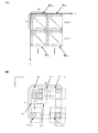
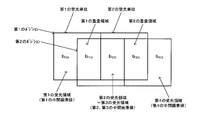
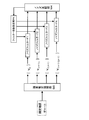
- 1A and 1B are schematic explanatory diagrams of an estimation processing block and a light receiving unit used for pixel estimation.
- pixels on the image sensor are indicated by solid-line squares
- pixel positions in the horizontal direction (horizontal scanning direction) are indicated by i
- pixel positions in the vertical direction are indicated by j ( i and j are natural numbers).
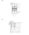
- estimation processing blocks Bk 00 , Bk 10 ,... With m ⁇ n pixels as one block are set.
- pixel value estimation processing for a high resolution image is performed for each estimation processing block.
- FIG. 1B schematically shows one of the above estimation processing blocks.
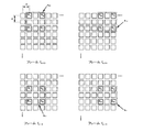
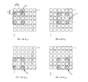
- four pixels (a plurality of pixels in a broad sense) are set as one light receiving unit, and pixel values of four pixels in the light receiving unit are added and read (mixed reading) to receive light.
- the unit light reception values a 00 to a (m ⁇ 1) (n ⁇ 1) are acquired.
- This light reception unit is set for every four pixels, and the light reception values a 00 to a (m ⁇ 1) (n ⁇ 1) are sequentially obtained by setting the light reception unit by shifting one pixel at a time for each frame. For example, a 00 , a 20 ,... Are acquired in the first frame, a 10 , a 30 ,... Are acquired in the second frame, and a 11 , a 31 ,. And a 01 , a 21 ,... Are acquired in the fourth frame.
- a pixel estimation method will be described with reference to FIGS.
- the light reception values a 00 to a 11 used for pixel estimation may be the light reception values themselves acquired by addition reading, or may be light reception values interpolated by time axis interpolation described later.
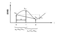
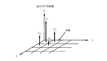
- FIG. 2A and 2B are explanatory diagrams of the estimated pixel value and the intermediate pixel value.
- the pixel values v 00 to v 22 are finally estimated using the received light values a 00 to a 11 . That is, assuming that the pixel pitch of the image sensor is p, a high resolution image having the same resolution (number of pixels) as that of the image sensor having the pixel pitch p is estimated from the low resolution image acquired by the light receiving unit having the pixel pitch 2p.
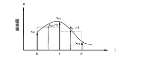
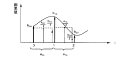
- an intermediate pixel value b 00 to b 21 (intermediate estimated pixel value, two-pixel added value) is estimated from the received light values a 00 to a 11 and the intermediate pixel value b 00 Pixel values v 00 to v 22 are estimated from .about.b 21 .
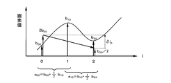
- This intermediate pixel value estimation method will be described using the intermediate pixel values b 00 to b 20 in the first horizontal row shown in FIG. 3 as an example.
- the intermediate pixel values b 10 and b 20 can be expressed as a function of b 00 as shown in the following equation (2).
- b 00 (unknown number)
- b 10 a 00 -b 00
- ⁇ i 0 is a difference value between the received light values one shift away, and corresponds to the difference value between the intermediate pixel values b 20 and b 00 .
- a pattern ⁇ a 00 , a 10 ⁇ based on pixel values detected by superposition shift sampling is compared with a pattern ⁇ b 00 , b 10 , b 20 ⁇ based on intermediate pixel values. Then, an unknown number b 00 that minimizes the error is derived, and the derived unknown number b 00 is set as the final intermediate pixel value b 00 .
- error evaluation is performed on the average value of the intermediate pixel values and the pattern ⁇ a 00 , a 10 ⁇ having a low frequency component.
- the pattern including many high frequency components as the estimated solution of the intermediate pixel values ⁇ b 00, b 10, b 20 ⁇ is derived. That is, even if the estimation of the unknown is inaccurate, an image including a large amount of low frequency components is generated. For this reason, it is possible to suppress generation of a pattern including an error in a high frequency component in which unnaturalness is more easily emphasized than in a low frequency component, and the natural appearance of the image is not lost. Thereby, rational pixel estimation is possible for a natural image having a small high frequency component compared to a low frequency component.
- the value of the intermediate pixel value b 00 is estimated, and the estimated value of b 00 is substituted into the above equation (2) to determine the values of the intermediate pixel values b 10 and b 20 .
- the intermediate pixel values b 01 to b 21 in the second row are estimated using b 01 as an unknown number.
- 6A and 6B schematically illustrate the intermediate pixel value and the estimated pixel value.
- estimation is performed using two columns of intermediate pixel values b 00 to b 11 out of the three columns of intermediate pixel values b 00 to b 21 estimated by the above-described method.
- pixel values v 00 to v 12 are estimated from the intermediate pixel values b 00 to b 11 .
- the pixel values v 00 to v 02 in the first column shown in FIG. 7 will be described as an example.
- the pixel values v 00 to v 02 are estimated by a method similar to the above-described intermediate pixel value estimation method.
- the intermediate pixel values b 00 and b 01 are equivalent to values obtained by superimposing and sampling the pixel values v 00 to v 02 while shifting the pixel values v 00 to v 02 one pixel at a time in the vertical direction. Therefore, the relationship of the following formula (5) is established between the intermediate pixel value and the estimated pixel value.
- b 00 v 00 + v 01
- b 01 v 01 + v 02 (5)
- the pixel values v 01 and v 02 can be expressed as a function of the unknown v 00 .
- v 00 (unknown number)
- v 01 b 00 ⁇ v 00
- ⁇ j 0 is a difference value between the intermediate pixel values separated by one shift, and corresponds to the difference value between the pixel values v 02 and v 00 .
- pixel values v 10 to v 12 in the second column are obtained by the same processing, and final estimated pixel values v 00 , v 01 , v 10 , and v 11 are determined.
- an appropriate noise reduction process may be performed on the image data composed of the final estimated pixel values to obtain a display image.
- the method of switching between the still image shooting mode and the moving image shooting mode has a problem that when the user notices a photo opportunity, a decisive moment is often already missed.
- the method of synthesizing a high-resolution still image from a low-resolution moving image by super-resolution processing since the super-resolution processing is a heavy load processing, there is a problem that the scale of the processing circuit increases. is there.
- a light reception unit which is a unit for acquiring a light reception value (addition pixel value, four pixel addition value), is set for each of a plurality of pixels of the image sensor. Pixel values of a plurality of pixels included in the unit are added and read as a light reception value of the light reception unit, and a low resolution frame image is acquired. Then, the acquired low-resolution frame image is stored, and the pixel value of each pixel included in the light receiving unit is estimated based on the plurality of stored low-resolution frame images. Based on the estimated pixel value, a high-resolution frame image having a higher resolution than the low-resolution frame image is output.
- the low-resolution frame image is acquired by reading the light reception value of the light reception unit while sequentially shifting the pixels while superimposing the light reception units. Then, the pixel value of each pixel included in the light reception unit is estimated based on a plurality of light reception values obtained by sequentially shifting the light reception unit.
- the light receiving unit is set every four pixels.
- the received light values a 00 , a 20 ,... Are added and read out in the first frame, and a low-resolution frame image composed of a 00 , a 20 ,.
- the constructed low resolution frame images are sequentially acquired.
- the light reception units for obtaining the light reception values a 00 , a 10 , a 11 , and a 01 are shifted in the horizontal direction or the vertical direction by one pixel, and are shifted while superposing two pixels.
- These low-resolution frame images are acquired by, for example, an imaging device described later with reference to FIG.
- the acquired low-resolution frame image is input to an image processing apparatus to be described later with reference to FIG. 31, for example, and stored in a storage unit such as a memory (not shown).
- a storage unit such as a memory (not shown).
- each pixel value in the estimation processing block is estimated.
- a high resolution image corresponding to the resolution of the image sensor is output from the estimated pixel value.
- the estimation process can be simplified using the above-described estimation of the intermediate pixel value.
- the high-resolution still image can be generated at any timing of the low-resolution moving image, the user can easily obtain the high-resolution still image at the decisive moment.
- a low-resolution video eg 3 megapixels
- a high frame rate eg 60 frames
- a high-resolution still image (12 megapixels) or a high-definition video is displayed as needed. it can.
- the light receiving unit is sequentially set to the first position and the second position next to the first position by pixel shift.
- the light receiving units at the first and second positions overlap.
- the difference value of the light reception value of the light reception unit of the 1st, 2nd position is calculated
- the first intermediate pixel value which is the light receiving value of the first light receiving area obtained by removing the overlapping area from the light receiving unit of the first position, and the second light receiving area obtained by removing the overlapping area from the light receiving unit of the second position.
- a relational expression with the second intermediate pixel value that is the light reception value is expressed using the difference value.
- the first and second intermediate pixel values are estimated using the relational expression, and the pixel value of each pixel of the light receiving unit is obtained using the estimated first intermediate pixel value.
- the in the first frame, the first position to the light receiving unit is configured to obtain the received-light value a 00, in the second frame, second to obtain the received-light value a 10
- the light reception unit is set at the position.
- These light receiving units are overlapped in a region including the estimated pixels v 10 and v 11 .
- the area including the estimated pixels v 00 and v 01 corresponds to the first light receiving area
- the intermediate pixel value b 00 of the area is the first intermediate area. Corresponds to the pixel value.
- a region including the estimated pixels v 20 and v 21 corresponds to the second light receiving region, and an intermediate pixel value b 20 in the region corresponds to the second intermediate pixel value.
- it is estimated unknown b 00, b 20 are estimated using the relational expression.
- estimated pixel values v 00 and v 01 are obtained using b 00 .
- the relationship between the intermediate pixel values of the intermediate pixel value pattern is expressed using the light reception value of the light reception unit. Then, the similarity is evaluated by comparing the intermediate pixel value pattern with the light reception value pattern (light reception value of the light reception unit), and based on the evaluation result, the intermediate pixel of the intermediate pixel value pattern so that the similarity is the highest. The value value is determined.
- successive intermediate pixel values ⁇ b 00 , b 10 , b 20 ⁇ correspond to the intermediate pixel value pattern
- ⁇ b 00 , b 10 , b 20 ⁇ is expressed using received light values a 00 and a 10 .
- the intermediate pixel value pattern ⁇ b 00 , b 10 , b 20 ⁇ is compared with the received light value pattern ⁇ a 00 , a 10 ⁇ , and ⁇ b 00 , so that the similarity represented by the evaluation function Ej is the highest.
- the values of b 10 , b 20 ⁇ are determined.
- the light reception value pattern ⁇ a 00 , a 10 ⁇ is a light reception value that is continuous in the horizontal direction (in a continuous order).
- an intermediate pixel value can be estimated based on a plurality of light reception values acquired by pixel shifting while superimposing light reception units.
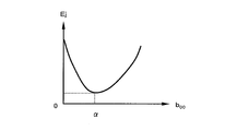
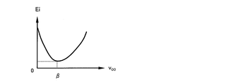
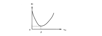
- an evaluation function representing an error between the intermediate pixel value pattern represented by the relational expression between the intermediate pixel values and the light reception value pattern (light reception value of the light reception unit) is obtained. Then, the value of the intermediate pixel value of the intermediate pixel value pattern is determined so that the value of the evaluation function is minimized.
- the intermediate pixel value pattern ⁇ b 00 , b 10 , b 20 ⁇ is expressed as a function of the unknown b 00 as described above in the above equation (4) or the like, and the intermediate pixel value pattern ⁇ b 00 , b 10 , b 20 ⁇ and the light-receiving value pattern ⁇ a 00, the error between a 10 ⁇ is expressed by the evaluation function Ej.
- the unknown b 00 ⁇ (initial value) that minimizes the value of the evaluation function Ej is obtained, and the values b 00 to b 20 are determined based on the obtained b 00 .
- the value of the intermediate pixel value can be estimated by expressing the error by the evaluation function and obtaining the intermediate pixel value corresponding to the minimum value of the evaluation function.
- the initial value of the intermediate pixel estimation can be set with a simple process by obtaining the unknown using the least square method. That is, as compared with the above-described comparative example (Patent Document 2), it is not necessary to search for an image part suitable for initial value setting.
- the intermediate pixel value b 20 is estimated.
- This b 20 corresponds to an unknown (initial variable) in the next estimation processing block set to the intermediate pixel values b 20 and b 30 .
- a second estimation method capable of speeding up the estimation of unknowns will be described with reference to FIGS.
- the estimation of the intermediate pixel value (b 20 etc.) will be described as an example, but the estimation pixel (v 02 etc.) can be similarly estimated.
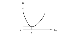
- equation (13) represents the evaluation function Ej of the error as a function of unknown b 00.
- ⁇ i 2 is the difference value of the received light value one shift away, and is expressed by the following equation (16).
- equation (17) represents the evaluation function Ej of the error as a function of unknown b 20.
- the value of b 20 has already been obtained by estimating the intermediate pixel values b 00 to b 20 .
- the first light receiving unit and the second light receiving unit are adjacent light receiving units. Then, the first and second light receiving units are sequentially set to the first position and the second position next to the first position by the pixel shift. The first light receiving units at the first and second positions overlap in the first overlapping region, and the second light receiving units at the first and second positions overlap in the second overlapping region.
- a region obtained by removing the first overlapping region from the first light receiving unit at the first position is the first light receiving region.
- a region obtained by removing the first overlapping region from the first light receiving unit at the second position is a second light receiving region.
- the scope of searching for unknown (b 20) it can be reduced search times.
- the unknown number (b 00 , b 20, etc.) is estimated only once.
- the unknown number is estimated a plurality of times, and the unknown number is estimated based on the plurality of estimated values.
- the value may be determined with high accuracy.
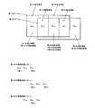
- a third estimation method for determining an unknown value from a plurality of estimated values will be described with reference to FIGS. 16 and 17.
- the intermediate pixel value (b 20 ) will be described as an example, but the estimated pixel value (v 02 and the like) can be similarly estimated.
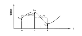
- a high-definition intermediate pixel value ⁇ 1 ⁇ b 10 , b 20 , b 30 ⁇ is obtained from ⁇ a 10 , a 20 ⁇ by the same method as the above equations (14) to (17).
- a high-definition intermediate pixel value ⁇ 2 ⁇ b 20 , b 30 , b 40 ⁇ is obtained from ⁇ a 20 , a 30 ⁇ by the same method as the above equations (14) to (17).
- the intermediate pixel value b 20 appears in each of the sets ⁇ 0 , ⁇ 1 , ⁇ 2 . Therefore, three estimated values of the intermediate pixel value b 20 are obtained by three estimations.
- the final intermediate pixel value b 20 is determined (determined) from these three estimated values. For example, it can be determined by the following first to fourth determination methods.
- an average value of the three b 20 candidate values is set as the final determination value of b 20 .
- the second determination method two values having the smallest difference among the three b 20 candidate values are specified, and an average value of the two specified values is set as a final determination value of b 20 .
- two estimated values that are close to each other are assumed to be probable estimated values, and the estimation accuracy of unknowns can be improved.
- pixel values of a large number of known high-resolution image samples are added to obtain a light reception value and an intermediate pixel value.
- An intermediate pixel value pattern having a high probability of occurrence with respect to the received light value pattern is specified in advance from the obtained received light value and intermediate pixel value.
- an intermediate pixel value pattern having a high occurrence probability with respect to the received light value pattern acquired by photographing is obtained with reference to the correspondence relationship specified in advance.
- the three intermediate pixel value patterns ⁇ 0 , ⁇ 1 , ⁇ 2 the one closest to the obtained intermediate pixel value pattern is determined, and b 20 that is an element of the determined intermediate pixel value pattern is most probable.
- b Final decision value of 20 According to this method, it is possible to perform pixel value estimation reflecting a known image such as a natural image.
- b 20 to be finally adopted is determined according to the degree of change in the difference values ⁇ i 0 , ⁇ i 1 , ⁇ i 2 of the neighboring observation pixel values a 00 to a 30 related to the derivation of the three b 20.
- An occurrence probability distribution of b 20 for the combination pattern ⁇ is obtained in advance from the obtained element pattern and combination pattern ⁇ .
- the occurrence probability distribution of b 20 with respect to the difference value pattern ⁇ obtained from the captured image is obtained with reference to the occurrence probability distribution obtained in advance.
- the most probable value of b 20 can be determined from According to this method, it is possible to perform pixel value estimation reflecting a known image such as a natural image. Further, it is possible to perform pixel value estimation according to the degree of change in the pixel value regardless of the size of the pixel value.
- the first light receiving unit and the second light receiving unit are adjacent light receiving units. Then, the first and second light receiving units are sequentially set to the first position and the second position next to the first position by the pixel shift. The first light receiving units at the first and second positions overlap in the first overlapping region, and the second light receiving units at the first and second positions overlap in the second overlapping region.
- a region obtained by removing the first overlapping region from the first light receiving unit at the first position is the first light receiving region.
- a region obtained by removing the first overlapping region from the first light receiving unit at the second position is a second light receiving region.
- the overlapping region of the first light receiving unit at the second position and the second light receiving unit at the first position is the fifth light receiving region. Then, successive intermediate pixel values that include the fifth intermediate pixel value (b 20 ) that is the light reception value of the fifth light receiving region and do not include the first and fourth intermediate pixel values (b 00 , b 40 ).
- a third intermediate pixel value pattern ( ⁇ 1 ⁇ b 10 , b 20 , b 30 ⁇ ) is estimated.
- the third and fifth light receiving areas are the same light receiving areas as the second light receiving areas.
- the second, third, and second intermediate pixel values (b 20 ) of the same light receiving region are obtained by estimating the first to third intermediate pixel value patterns ( ⁇ 0 , ⁇ 2 , ⁇ 1 ). Finally, it is determined based on the intermediate pixel value (b 20 ) of 5.
- the final pixel value can be determined based on the three (plural) estimated values obtained by estimating three (plural times). For example, by using a determination method using a known image as described above, it is possible to estimate a pixel value in accordance with a pixel value pattern of an actual image.
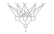
- the pixel value is estimated using the least square method, but in the present embodiment, the pixel value may be estimated using a neural network (nonlinear estimation method).
- the fourth estimation method will be described with reference to FIG. In the following, the estimation of the intermediate pixel value (b 00 etc.) will be described, but the estimated pixel value (v 00 etc.) can be similarly estimated.
- the weighting factor W is calculated in advance by learning calculation of the neural network shown in FIG. Specifically, the weighting factor W is calculated so that the error evaluation value E shown in the following formula (18) becomes zero (including substantially zero, which is a predetermined value in a broad sense).
- a learning method of the neural network a general neural network learning method may be used.
- the similarity is evaluated based on the foreseeing information acquired based on the known high-resolution frame image, so image information (for example, spatial frequency characteristics) included in the known image such as a natural image. Can be estimated.
- the image processing apparatus has a neural network.
- This neural network uses, as look-ahead information, a node weighting factor W obtained by learning based on a known high-resolution frame image.
- the sex evaluation result E is output.
- the similarity between the intermediate pixel value pattern and the light receiving value of the light receiving unit can be evaluated based on the foresight information by the neural network using the node weighting coefficient W obtained by learning.
- the pixel value can be estimated using the occurrence probability distribution of the pixel value as foresight information.
- a pixel value having a high probability of occurrence in a known image such as a natural image can be used as an estimated value.
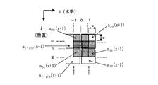
- noise filter processing (filter processing in a broad sense) corresponding to a pixel position (for example, a pixel position within a light receiving unit) is performed on the estimated pixel value v ij . Good.
- FIG. 19 shows a configuration example of the noise filter.
- the filter coefficients are set so that the noise appearance is the same (substantially the same) regardless of the positions of v ij to v (i + 1) (j + 1) .
- the pixel values v ij to v (i + 1) (j + 1) obtained by estimation are subjected to filter processing with different filter coefficients depending on the pixel position in the light receiving unit.
- the noise can be reduced by performing the noise filter processing according to the pixel position in the light receiving unit.
- the weighting coefficients for addition reading are c 1 , c 2 , c 3 , and c 4 .
- c 1 1
- the weighting coefficient takes the ratio relationship rule shown in the following equation (19) (r is a real number with r> 1).
- the weighted pixel addition values are set to a 00 , a 10 , and a 20 in the shift order.
- a 00 c 1 v 00 + c 2 v 01 + c 3 v 10 + c 4 v 11
- a 10 c 1 v 10 + c 2 v 11 + c 3 v 20 + c 4 v 21 ⁇
- b 00 , b 10 , and b 20 are defined as shown in the following formula (22), and the above formula (20) is substituted.
- b 00 (unknown number)
- b 10 2 (a 00 -b 00 )
- a pattern ⁇ a 00 , a 10 ⁇ based on sampling pixel values detected by weighted superposition shift sampling and a pattern based on intermediate pixel values ⁇ b 00 , b 10 , b 20 ⁇ are compared. Then, an unknown number b 00 that minimizes the error E is derived and set as the intermediate pixel value b 00 .
- the evaluation function Ej shown in the following equation (27) is obtained. Then, the similarity between the pattern ⁇ a 00 , a 10 ⁇ and the intermediate estimated pixel value ⁇ b 00 , b 10 , b 20 ⁇ is evaluated using this evaluation function Ej.
- v 00 (unknown number)
- v 01 2 (b 00 ⁇ v 00 )
- the estimated pixel value pattern ⁇ v 00 , v 01 , v 02 ⁇ of the above equation (30) is compared with the intermediate pixel value pattern ⁇ b 00 , b 01 ⁇ , and an unknown v 00 that minimizes the error Ei is derived. .
- b ij v ij + (1/2) v i (j + 1) (31)
- the patterns are compared in consideration of the weighting shown in the above equation (31). Specifically, the evaluation function Ei shown in the following equation (32) is obtained.
- each pixel value of the light receiving unit is weighted and added to obtain a low-resolution frame image, and the pixel value of the high-resolution frame image can be estimated from the obtained low-resolution frame image.
- the reproducibility of the high-frequency component of the subject can be improved. That is, when the pixel values of the light receiving units are simply added, a rectangular window function is convoluted for imaging.
- a window function containing more high frequency components than the rectangle is convoluted for imaging. Therefore, it is possible to acquire a low-resolution frame image that includes more high-frequency components of the subject, and improve the reproducibility of the high-frequency components in the estimated image.
- the light reception value (a 00 or the like) used for estimating the pixel value the light reception value read out by addition may be used as it is, or the light reception value generated by interpolation may be used. .
- the received light value interpolation method in this embodiment will be described with reference to FIGS.
- FIG. 29 is an explanatory diagram of the first interpolation method.
- the frame used in the following description refers to, for example, the timing at which one low-resolution frame image is captured by the image sensor or the timing at which one low-resolution frame image is processed in image processing.
- one low-resolution frame image or high-resolution frame image in image data is also referred to as a frame as appropriate.
- the received light value of the interpolation target frame is interpolated using the received light value acquired in another frame (time axis interpolation).
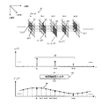
- received light values a ij , a (i + 1) j , a (i + 1) (j + 1) , and a i (j + 1) are sequentially acquired in frames fx to fx + 3.
- the light reception value a ij is acquired again.
- a low-resolution frame image composed of the received light value a ij is acquired in frames fx, fx + 4, and fx + 8.
- time-axis interpolation filter processing (filter processing) is performed on the time-series data of the light reception values aij .
- the light reception value a ′ ij is generated in all frames (each frame) by this time axis interpolation filter processing.
- each received light value is acquired every four frames, and time axis interpolation filter processing is performed, and the received light values a ′ ij , a ′ (i + 1) j , a ′ (i + 1) (j + 1) , a ′ i (j + 1) is generated.
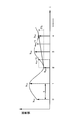
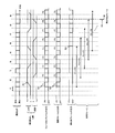
- FIG. 30 shows an example timing chart of the interpolation process.
- the light receiving unit setting position is shifted by one pixel.
- the fusion frames F1, F2,... Low resolution frame images
- a low-resolution moving image frame is generated, and live view display and recording are performed.
- time axis interpolation of the received light value is performed, pixel value estimation is performed using the received light value after interpolation, and a high-resolution still image frame is generated.
- a high-resolution still image or a high-resolution moving image is output from the ninth frame in which all received light values are interpolated.
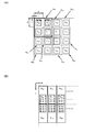
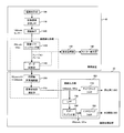
- FIG. 31 shows a first detailed configuration example of the imaging device and the image processing device.
- 31 includes an imaging optical system 100 (lens), an optical low-pass filter 110, an imaging element 120 (image sensor), a superposition shift sampling unit 130 (reading control unit), a data recording unit 140 (storage unit), A display processing unit 150 (display control unit) and a monitor display unit 160 (display device) are included.
- the image processing apparatus 20 includes a time axis pixel interpolation unit 200 (interpolation processing unit), a pixel value estimation calculation unit 210 (estimation processing unit), and an image output unit 300.
- FIG. 31 illustrates an example in which the image processing device 20 is provided outside the imaging device 10, but in the present embodiment, the image processing device 20 may be provided inside the imaging device 10.
- the imaging device 10 is, for example, a digital camera or a video camera.
- the imaging optical system 100 forms an image of a subject.
- the optical low-pass filter 110 passes a band corresponding to the resolution of the image sensor 120, for example.
- the image sensor 120 (for example, 12 megapixels) is configured by, for example, a CCD or CMOS sensor that can be added and read in an analog manner.
- the superposition shift sampling unit 130 controls, for example, setting of light reception units and addition reading, and acquires a fusion frame (for example, 3 megapixels).
- the data recording unit 140 is realized by, for example, a memory card or the like, and records a moving image by a fusion frame.
- the monitor display unit 160 displays a live view of a moving image and a reproduced moving image.
- the image processing apparatus 20 is realized by, for example, an image processing engine (IC) or a PC (computer).
- the time axis pixel interpolation unit 200 performs time axis interpolation of the received light value of the fusion frame.
- the pixel value estimation calculation unit 210 estimates a final estimated pixel value.
- the image output unit 300 includes anti-aliasing filters 220 and 250, a low-pass filter 230, and an undersampling unit 240, and outputs a still image or a moving image from the final estimated pixel value.
- the anti-aliasing filter 220 performs anti-aliasing processing on the final estimated pixel value and outputs a high-resolution still image (for example, 12 megapixels).
- the low pass filter 230 limits the final estimated pixel value to the high vision band.
- the undersampling unit 240 undersamples the band-limited final estimated pixel value to the number of high-definition pixels.
- the anti-aliasing filter 220 performs anti-aliasing processing on the undersampled image and outputs a high-definition moving image (for example, 2 megapixels). Note that a high-resolution moving image (for example, 12 megapixels) may be output without undersampling.
- the received light value is interpolated by the time axis filter process.
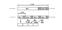
- the received light value may be interpolated by motion compensation. For example, as shown in FIG. 32, four continuous fusion frames photographed at a high frame rate (1/60 seconds) are used, and motion compensation is performed on each fusion frame to produce one still image (low frame). A high-definition image taken at a rate of 1/15 seconds) may be generated.
- the low-resolution frame images are sequentially acquired by shifting the pixels, four frames are required to acquire all the received light values used for pixel value estimation. Therefore, if the photographed received light value is used for pixel value estimation as it is, the received light value of a different frame is used for estimation, and the image quality may be deteriorated when the subject is moving.
- the pixel shift is performed in each frame fx, fx + 1,...,
- the light reception unit has a plurality of positions (4 positions; P1 to P4 shown in FIG. 29 described above). Are set sequentially. Then, the light receiving unit is set to the same position for each of a plurality of frames (every 4 frames). In this way, the received light values a ij to a (i + 1) (j + 1) corresponding to the respective positions in time series are acquired, and low resolution frame images are acquired in time series using the acquired received light values (continuous low Resolution frame image).
- a process of interpolating the light reception values a ′ ij to a ′ (i + 1) (j + 1) of the light reception units at a plurality of positions P1 to P4 is performed on the acquired continuous low-resolution frame image.
- the light-receiving value (a ′ ij ) of the light-receiving unit at the missing position (eg, P1) in the continuous low-resolution frame image of the frame to be interpolated (eg, fx + 1) is time-axis interpolated.
- the light reception value (a ′ ij ) is the light reception unit in the continuous low-resolution frame image of the frames (fx, fx + 4) before and after the interpolation target frame (fx + 1) at the same position (P1) as the missing position.
- Time axis interpolation is performed using the received light value (a ij ).
- the received light value is acquired by the pixel shift, and the received light value at the missing position is interpolated using the acquired received light value, and the final estimated pixel value can be obtained from the received light value after interpolation.
- the pixel value is estimated from the light reception values in the same frame, and image quality deterioration can be suppressed even when the subject is moving.
- the time axis interpolation is performed by the time axis interpolation filter.
- the received light value (a ij of fx, fx + 4) at each position (for example, P1) is time-axis interpolated to generate the received light value (a ′ ij ) of the missing position (P1 of fx + 1 to fx + 3).
- the image output unit 300 generates a high-resolution frame image in each frame based on the final estimated pixel value in each frame estimated by the pixel value estimation calculation unit 210, and generates The high-resolution frame image is output as a still image or a moving image.
- adaptive received light value interpolation may be performed according to the movement of the subject.
- a second interpolation method for adaptively interpolating received light values will be described with reference to FIGS. 33 and 34.
- the received light values of the frames before and after the neighborhood are applied to a portion where there is no motion or a small amount (light reception value), and the light reception value is superimposed on the adjacent light reception value in the same frame for a portion where the motion is large or large. Interpolate the shifted received light value.
- the motion compensation process may be performed in advance.
- FIG. 34 shows a part of the received light value acquired as the imaging data in the frame fx + 1 for the sake of simplicity.
- the acquired light reception values are indicated by a 10 (x + 1), a ( ⁇ 1) 0 (x + 1), a ( ⁇ 1) 2 (x + 1), and a 12 (x + 1).
- a 00 (x) and a 00 (x + 4) of the neighboring frames fx and fx + 4 acquired at the corresponding position of a 00 (x + 1) are compared.
- the difference is smaller than the predetermined threshold ⁇ , it is determined that the subject (a part of the moving subject) has not passed through the pixel position corresponding to a 00 (x + 1) between the frames fx and fx + 4.
- assign a 00 (x + 1) a as a value of 00 (x) or a 00 (x + 4).
- an interpolated value is obtained using received light values a 10 (x + 1) and a ( ⁇ 1) 0 (x + 1) close to a 00 (x + 1) in the same frame, and a 00 ( x + 1).
- an average value of a 10 (x + 1) and a ( ⁇ 1) 0 (x + 1) is set as a 00 (x + 1).
- interpolation may be performed using a larger number of peripheral light reception values instead of the average of two adjacent light reception values.
- a 11 (x + 1) is interpolated by the following equation (34).
- a 01 (x + 1) is interpolated by the following equation (35).
- a 01 (x + 1) ⁇ a 10 (x + 1) + a ( ⁇ 1) 2 (x + 1) ⁇ / 2 (35)
- the threshold value ⁇ may be set by evaluating the quality of the generated image and setting an allowable level threshold value ⁇ . For example, it may be set to a level at which it is not determined that there is movement due to noise in spite of a still image.
- the difference value (a 00 (x) ⁇ a 00 (x + 4)) of the received light value of the received light unit in the frames (for example, fx, fx + 4) before and after the frame to be interpolated (for example, fx + 1). ) Is required.
- the difference value is smaller than the predetermined threshold ⁇
- the light reception value (a 00 (x + 1)) of the light reception unit at the missing position (position) in the interpolation target frame (fx + 1) is the previous or next frame (fx).
- Fx + 4) is interpolated using the received light value (a 00 (x), a 00 (x + 4)) of the received light unit at the same position as the missing position.
- the light reception value (a 00 (x + 1)) of the light reception unit at the missing position in the interpolation target frame (fx + 1) is the interpolation target frame (fx + 1). Interpolation is performed using the received light reception values (a 10 (x + 1), a ( ⁇ 1) 0 (x + 1)).
- the received light value can be adaptively interpolated according to the movement of the subject.
- the received light value acquired at the same position is used, so that the positional error can be reduced.
- a temporal error can be reduced.
- the subject passes between the frames fx and fx + 4 cannot be known from the received light values a 00 (x) and a 00 (x + 4). Therefore, when interpolating from a 00 (x) and a 00 (x + 4), the influence of the movement of the subject appears even at the timing before the passage timing of the subject.
- interpolation is performed using the light reception value of the same frame, so that the passage timing of the subject can be accurately reflected.
- the second interpolation method it is possible to suppress image quality deterioration due to erroneous detection of motion. For example, if there is a mere change in brightness exceeding a predetermined threshold ⁇ within the four-frame imaging period, there is a possibility that a mere change in brightness is erroneously detected as the movement of the subject. In this regard, according to the second interpolation method, even if erroneous detection is performed, it is only possible to switch to intra-frame interpolation, so that it is possible to prevent the image quality from deteriorating significantly.
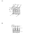
- RGB is read without being separated, and the final pixel value of RGB is estimated.
- the received light values a 00 , a 10 , a 01 , a 11 shown in the following formula (36) are sequentially acquired.
- a 00 R 10 + G1 00 + G2 11 + B 01
- a 10 R 10 + G1 20 + G2 11 + B 21
- a 01 R 12 + G1 02 + G2 11 + B 01
- a 11 R 12 + G1 22 + G2 11 + B 21 ⁇ (36)
- the image sensor is a color image sensor (RGB single-plate image sensor), and a plurality of adjacent pixels (for example, G1 00 , R 10 , B 01 , G2 11 ).
- the light receiving unit is set regardless of the pixel color.
- pixel values (G1 00 , R 10 , B 01 , G2 11 ) of each pixel of the light receiving unit are estimated based on the acquired low-resolution frame image, and color high resolution is based on the estimated pixel value.
- a frame image (still image or moving image) is output.
- a low-resolution frame image is captured at a high frame rate, and a pixel value is estimated from the low-resolution frame image to obtain a color high-resolution frame image at an arbitrary timing. it can.
- the received light value is obtained by adding the pixel values of the four adjacent pixels, random noise can be reduced.
- peripheral pixels with higher correlation can be used in intra-frame pixel interpolation in the second interpolation method described above.
- RGB final pixel values may be estimated by separating and adding RGB.
- a second color image estimation method will be described with reference to FIGS.
- the received light value represented by the following equation (37) is acquired by superposition sampling for the G1 pixel.
- the final estimated pixel G1 is estimated from these light reception values.
- a 00 G1 00 + G1 20 + G1 02 + G1 22
- a 10 G1 20 + G1 40 + G1 22 + G1 42
- a 01 G1 02 + G1 22 + G1 04 + G1 24
- a 11 G1 22 + G1 42 + G1 24 + G1 44 (37)
- the light reception value shown in the following equation (38) is acquired for the G2 pixel.
- the final estimated pixel G2 is estimated from these received light values.
- a 00 G2 11 + G2 31 + G2 13 + G2 33
- a 10 G2 31 + G2 51 + G2 33 + G2 53
- a 01 G2 13 + G2 33 + G2 15 + G2 35
- a 11 G2 33 + G2 53 + G2 35 + G2 55 (38)
- the received light value shown in the following equation (39) is acquired for the R pixel.
- the final estimated pixel R is estimated from these received light values.
- a 00 R 10 + R 30 + R 12 + R 32
- a 10 R 30 + R 50 + R 32 + R 52
- a 01 R 12 + R 32 + R 14 + R 34
- a 11 R 32 + R 52 + R 34 + R 54 (39)
- the light reception value shown in the following equation (40) is acquired for the B pixel.
- the final estimated pixel B is estimated from these received light values.
- a 00 B 01 + B 21 + B 03 + B 23
- a 10 B 21 + B 41 + B 23 + B 43
- a 01 B 03 + B 23 + B 05 + B 25
- a 11 B 23 + B 43 + B 25 + B 45 (40)
- a plurality of pixels of the same color for example, G1 00 , G1 20 , G1 02 , G1 22
- pixel values (G1, G2, R, B) of each pixel of the light receiving unit are estimated based on the acquired low resolution frame image, and a color high resolution frame image is output based on the estimated pixel value. Is done.
- a color high-resolution frame image can be obtained by photographing a low-resolution frame image at a high frame rate for each color and estimating a pixel value from the low-resolution frame image.
- the light reception unit is set for every four pixels.
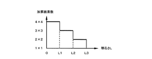
- the number of pixels set for the light reception unit is changed according to the brightness of the captured image. May be. A method for setting the number of added pixels adapted to this brightness will be described with reference to FIGS.
- pixel addition imaging of adjacent 2 ⁇ 2 pixels is basically performed, and pixel addition is performed when the average luminance value L (brightness in a broad sense) of the captured image is lower than a threshold value L2. Pixels are adjacent 3 ⁇ 3 pixels. When the average luminance value L falls below the threshold value L1 (L1 ⁇ L2), the number of pixels to be subjected to pixel addition is increased to 4 ⁇ 4 adjacent pixels. In this way, the number of pixels of the light receiving unit is set, and superposition shift sampling and pixel estimation are performed to obtain the pixel value of the high resolution image.
- FIG. 41 shows a second detailed configuration example of an imaging apparatus and an image processing apparatus that variably set the number of added pixels in accordance with brightness.
- 41 includes an imaging optical system 100, an optical low-pass filter 110, an imaging element 120, a superposition shift sampling unit 130, a data recording unit 140, a display processing unit 150, a monitor display unit 160, a brightness detection unit 170, An addition pixel number setting unit 180 is included.
- the image processing device 20 includes a time axis pixel interpolation unit 200, a pixel value estimation calculation unit 210, and an image output unit 300.
- the same components as those described above with reference to FIG. 31 and the like are denoted by the same reference numerals, and description thereof will be omitted as appropriate.
- the brightness detection unit 170 calculates the average luminance of an image captured by the image sensor 120 (for example, 16 megapixels).
- the superposition shift sampling unit 130 acquires a fusion frame (1 megapixel) with the set number of added pixels.
- the pixel value estimation calculation unit 210 estimates a final estimated pixel value (16 megapixels) from the fusion frame. Then, the image output unit 300 outputs a still image (16 megapixels) or a high-definition moving image (2 megapixels) from the final estimated pixel value.
- the number of pixels included in the light receiving unit is set to a larger number of pixels as the brightness (average luminance) of the subject is darker.
- the SN of random noise can be improved by increasing the number of added pixels as the subject is darker.
- the lower the resolution the higher the sensitivity of the estimated high-resolution frame image can be captured.
- imaging device 20 image processing device, 100 imaging optical system, 110 optical low-pass filter, 120 image sensor, 130 superposition shift sampling unit, 140 data recording unit, 150 display processing unit, 160 monitor display unit, 170 brightness detection unit, 180 additional pixel number setting unit, 200 time axis pixel interpolation unit, 210 pixel value estimation calculation unit, 220, 250 Anti-aliasing filter, 230 Low-pass filter, 240 undersampling unit, 300 image output unit, Bk 00 estimation processing block, a 00 received light unit, v 00 estimated pixel value, b 00 intermediate pixel value, p pixel pitch, i, j pixel position, difference value of ⁇ i 0 received light value, Ej, Ei evaluation function, c 1 to c 4 weighting factors, P1 to P4 positions, fx frame
Landscapes
- Engineering & Computer Science (AREA)
- Multimedia (AREA)
- Signal Processing (AREA)
- Theoretical Computer Science (AREA)
- Computing Systems (AREA)
- Physics & Mathematics (AREA)
- General Physics & Mathematics (AREA)
- Studio Devices (AREA)
- Image Processing (AREA)
- Color Television Image Signal Generators (AREA)
Abstract
簡素な処理で低解像動画から高解像画像を取得できる画像処理装置、撮像装置、プログラム及び画像処理方法等を提供すること。 【解決手段】受光単位が複数の画素毎に設定される。受光単位に含まれる複数の画素の画素値が加算されて受光値a00~a11として読み出され、低解像フレーム画像が取得される。画像処理装置は、複数の低解像フレーム画像に基づいて、受光単位に含まれる各画素の画素値v00~v11を推定する推定演算部と、推定された画素値に基づいて高解像フレーム画像を出力する画像出力部と、を含む。そして、受光単位を重畳しながら順次画素シフトさせつつ受光値a00~a11が読み出される。推定演算部は、画素シフトされることで得られた複数の受光値a00~a11に基づいて、受光単位に含まれる各画素の画素値v00~v11を推定する。
Description
本発明は、画像処理装置、撮像装置、プログラム及び画像処理方法等に関する。
昨今のデジタルカメラやビデオカメラには、静止画撮影モードと動画撮影モードを切り替えて使用できるものがある。例えば、動画撮影中にユーザがボタン操作をすることで、動画よりも高解像の静止画を撮影できるものがある。
しかしながら、静止画撮影モードと動画撮影モードを切り替える手法では、ユーザがシャッターチャンスに気付いたときには既に決定的瞬間を逃していることが多いという課題がある。
この決定的瞬間の撮影を実現するために、本発明者は、画素シフトの手法を利用して動画から任意タイミングの高解像静止画を生成することを考えている。画素シフトの手法として、例えば特許文献1、2には、画素シフトにより取得された低解像画像から高解像画像を合成する手法が開示されている。しかしながら、特許文献1、2の手法では、処理負荷の増大や、画素値の推定が困難な場合があるという課題がある。
本発明の幾つかの態様によれば、簡素な処理で低解像動画から高解像画像を取得できる画像処理装置、撮像装置、プログラム及び画像処理方法等を提供できる。
本発明の一態様は、受光値を取得する単位である受光単位が撮像素子の複数の画素毎に設定され、前記受光単位に含まれる複数の画素の画素値が加算されて前記受光単位の受光値として読み出され、低解像フレーム画像が取得される場合に、取得された前記低解像フレーム画像を記憶する記憶部と、前記記憶部に記憶された複数の低解像フレーム画像に基づいて、前記受光単位に含まれる各画素の画素値を推定する推定演算部と、前記推定演算部により推定された画素値に基づいて、前記低解像フレーム画像よりも高解像度の高解像フレーム画像を出力する画像出力部と、を含み、前記受光単位を重畳しながら順次画素シフトさせつつ前記受光単位の受光値が読み出されて、前記低解像フレーム画像が取得され、前記推定演算部は、前記受光単位が順次画素シフトされることで得られた複数の受光値に基づいて、前記受光単位に含まれる各画素の画素値を推定する画像処理装置に関係する。
本発明の一態様によれば、受光単位に含まれる複数の画素の画素値が加算されて受光値が読み出され、低解像フレーム画像が取得される。この受光値は、受光単位を重畳しながら順次画素シフトさせつつ読み出される。受光単位が順次画素シフトされることで得られた複数の受光値に基づいて、受光単位に含まれる各画素の画素値が推定され、推定された画素値に基づいて高解像フレーム画像が出力される。これにより、簡素な処理で低解像動画から高解像画像を取得すること等が可能になる。
また、本発明の一態様では、前記画素シフトにより、前記受光単位が、第1のポジションと、前記第1のポジションの次の第2のポジションに順次設定され、前記第1のポジションの受光単位と前記第2のポジションの受光単位が重畳する場合に、前記推定演算部は、前記第1、第2のポジションの受光単位の受光値の差分値を求め、前記第1のポジションの受光単位から重畳領域を除いた第1の受光領域の受光値である第1の中間画素値と、前記第2のポジションの受光単位から前記重畳領域を除いた第2の受光領域の受光値である第2の中間画素値との関係式を、前記差分値を用いて表し、前記関係式を用いて前記第1、第2の中間画素値を推定し、推定した前記第1の中間画素値を用いて前記受光単位の各画素の画素値を求めてもよい。
このようにすれば、受光単位が重畳しながら順次画素シフトさせつつ読み出された受光値から中間画素値を推定し、推定した中間画素値から最終的な推定画素値を求めることができる。これにより、高解像フレーム画像の画素値推定を簡素化できる。
また、本発明の一態様では、前記推定演算部は、前記第1、第2の中間画素値を含む連続する中間画素値を中間画素値パターンとする場合に、前記中間画素値パターンの中間画素値間の関係式を前記受光単位の受光値を用いて表し、中間画素値間の関係式で表された前記中間画素値パターンと前記受光単位の受光値とを比較して類似性を評価し、前記類似性の評価結果に基づいて、前記類似性が最も高くなるように前記中間画素値パターンの中間画素値の値を決定してもよい。
このようにすれば、受光単位が重畳されながら画素シフトされることで取得された複数の受光値に基づいて、中間画素値を推定できる。
また、本発明の一態様では、前記推定演算部は、中間画素値間の関係式で表された前記中間画素値パターンと前記受光単位の受光値との誤差を表す評価関数を求め、前記評価関数の値が最小となるように前記中間画素値パターンの中間画素値の値を決定してもよい。
このようにすれば、評価関数の値が最小となるように中間画素値の値を決定することで、中間画素値パターンと受光値の類似性が最も高くなるように中間画素値の値を決定できる。
また、本発明の一態様では、前記受光単位の受光値に対する前記中間画素値パターンの対応関係が、既知の高解像フレーム画像に基づいて、前記受光単位の受光値と前記中間画素値パターンの類似性をあらかじめ定める先見情報として取得され、前記推定演算部は、前記先見情報に基づいて、中間画素値間の関係式で表された前記中間画素値パターンと取得された前記受光単位の受光値との類似性を評価してもよい。
このようにすれば、既知の高解像フレーム画像に基づいて取得された先見情報に基づいて類似性を評価し、その評価結果に基づいて中間画素値を決定できる。
また、本発明の一態様では、前記推定演算部は、ノードの重み係数として、前記既知の高解像フレーム画像に基づく学習によって前記先見情報として得られた係数を用いるニューラルネットワークを有し、前記ニューラルネットワークは、中間画素値パターンと前記受光単位の受光値を受けて、前記類似性の評価結果を出力し、前記推定演算部は、前記ニューラルネットワークからの前記類似性の評価結果に基づいて前記中間画素値パターンの中間画素値の値を決定してもよい。
このようにすれば、ノードの重み係数を先見情報とするニューラルネットワークを用いることで、先見情報に基づく類似性評価を実現できる。
また、本発明の一態様では、前記受光単位の各画素値が重み付け加算されて前記受光単位の受光値として読み出され、前記推定演算部は、重み付け加算により得られた前記受光単位の受光値に基づいて、前記受光単位の各画素の画素値を推定してもよい。
このようにすれば、受光単位の各画素値を重み付け加算して低解像フレーム画像を取得し、取得した低解像フレーム画像から高解像フレーム画像の画素値を推定できる。
また、本発明の一態様では、前記画素シフトが各フレームで行われ、前記画素シフトにより前記受光単位が複数のポジションに順次設定され、複数のフレーム毎に前記受光単位が同じポジションに設定され、前記低解像フレーム画像は、時系列に各ポジションに対応して取得された連続低解像フレーム画像である場合に、前記各フレームでの前記複数のポジションの受光単位の受光値を補間する処理を行う補間処理部を含み、前記補間処理部は、補間対象のフレームの前記連続低解像フレーム画像での欠落したポジションの受光単位の受光値を、前記補間対象のフレームの前後のフレームの前記連続低解像フレーム画像での、前記欠落したポジションと同じポジションの受光単位の受光値を用いて時間軸補間し、前記推定演算部は、前記時間軸補間により補間された前記連続低解像フレーム画像に基づいて、前記各フレームでの前記受光単位の各画素の画素値を推定してもよい。
このようにすれば、画素シフトにより受光値が取得され、取得された受光値を用いて欠落したポジションの受光値を補間し、補間後の受光値から受光単位の各画素の画素値を求めることができる。
また、本発明の一態様では、前記画像出力部は、前記推定演算部により推定された前記各フレームでの前記受光単位の各画素の画素値に基づく各フレームでの前記高解像フレーム画像を、静止画または動画として出力してもよい。
このようにすれば、各フレームでの高解像フレーム画像を、静止画または動画として出力できる。
また、本発明の一態様では、前記補間処理部は、前記時間軸補間を時間軸補間フィルタにより行ってもよい。
このようにすれば、時間軸補間フィルタにより時間軸補間を行うことができる。
また、本発明の一態様では、前記補間処理部は、前記前後のフレームでの受光単位の受光値の差分値が所定の閾値より小さい場合には、前記補間対象のフレームでの前記欠落したポジションの受光単位の受光値を、前記前後のフレームでの、前記欠落したポジションと同じポジションの受光単位の受光値を用いて補間し、前記前後のフレームでの受光単位の受光値の差分値が所定の閾値より大きい場合には、前記補間対象のフレームでの前記欠落したポジションの受光単位の受光値を、前記補間対象のフレームで取得された受光値を用いて補間してもよい。
このようにすれば、補間対象のフレームの前後のフレームでの受光単位の受光値の差分値に応じて、補間対象のフレームでの受光値の時間軸補間を行うことができる。
また、本発明の一態様では、第1の受光単位と第2の受光単位が隣接する受光単位であり、画素シフトにより前記第1、第2の受光単位が、第1のポジションと、前記第1のポジションの次の第2のポジションに順次設定され、前記第1、第2のポジションの前記第1の受光単位が第1の重畳領域で重畳し、前記第1、第2のポジションの前記第2の受光単位が第2の重畳領域で重畳する場合に、前記推定演算部は、前記第1のポジションの前記第1の受光単位から前記第1の重畳領域を除いた第1の受光領域の受光値である第1の中間画素値と、前記第2のポジションの前記第1の受光単位から前記第1の重畳領域を除いた第2の受光領域の受光値である第2の中間画素値とを推定し、前記第1のポジションの前記第2の受光単位から前記第2の重畳領域を除いた第3の受光領域の受光値である第3の中間画素値を未知数とし、前記第2のポジションの前記第2の受光単位から前記第2の重畳領域を除いた第4の受光領域の受光値である第4の中間画素値を前記未知数を用いた関係式で表し、前記第3の受光領域と同じ領域である前記第2の受光領域の中間画素値として求めた前記第2の中間画素値に基づいて前記未知数の探索範囲を設定し、設定した前記探索範囲において前記未知数を探索的に求めて前記第3の中間画素値を推定してもよい。
このようにすれば、先に求めた第2の中間画素値に基づいて、次に推定する未知数の探索範囲を設定できる。
また、本発明の一態様では、第1の受光単位と第2の受光単位が隣接する受光単位であり、画素シフトにより前記第1、第2の受光単位が、第1のポジションと、前記第1のポジションの次の第2のポジションに順次設定され、前記第1、第2のポジションの前記第1の受光単位が第1の重畳領域で重畳し、前記第1、第2のポジションの前記第2の受光単位が第2の重畳領域で重畳する場合に、前記推定演算部は、前記第1のポジションの前記第1の受光単位から前記第1の重畳領域を除いた第1の受光領域の受光値である第1の中間画素値と、前記第2のポジションの前記第1の受光単位から前記第1の重畳領域を除いた第2の受光領域の受光値である第2の中間画素値とを含む連続する中間画素値である第1の中間画素値パターンを推定し、前記第1のポジションの前記第2の受光単位から前記第2の重畳領域を除いた第3の受光領域の受光値である第3の中間画素値と、前記第2のポジションの前記第2の受光単位から前記第2の重畳領域を除いた第4の受光領域の受光値である第4の中間画素値とを含む連続する中間画素値である第2の中間画素値パターンを推定し、前記第2のポジションの前記第1の受光単位と前記第1のポジションの前記第2の受光単位との重畳領域である第5の受光領域の受光値である第5の中間画素値を含み、前記第1、第4の中間画素値を含まない連続する中間画素値である第3の中間画素値パターンを推定し、前記第3、第5の受光領域が前記第2の受光領域と同一の受光領域である場合に、前記同一の受光領域の中間画素値を、前記第1~第3の中間画素値パターンの推定により得られた前記第2、第3、第5の中間画素値に基づいて最終的に決定してもよい。
このようにすれば、同一の受光領域の中間画素値を3回推定することで求めた3つの推定値に基づいて、その受光領域の最終的な中間画素値を決定できる。
また、本発明の一態様では、前記推定演算部は、推定により得られた画素値に対して、前記受光単位内での画素位置に応じて異なるフィルタ係数のフィルタ処理を行ってもよい。
このようにすれば、推定により得られた画素値に対して、受光単位内での画素位置に応じたフィルタ処理を行うことができる。
また、本発明の一態様では、前記受光単位に含まれる画素数が、被写体の明るさが暗いほど多い画素数に設定され、前記画像出力部は、前記被写体の明るさが暗いほど高感度の前記高解像フレーム画像を出力してもよい。
このようにすれば、被写体の明るさに応じて受光単位に含まれる画素数が設定され、被写体の明るさに応じた感度の高解像フレーム画像を出力できる。
また、本発明の一態様では、前記撮像素子がカラー撮像素子であり、隣接する複数の画素が、画素の色に依らず前記受光単位に設定され、前記受光単位に設定された前記隣接する複数の画素の画素値が加算されて読み出され、前記低解像度フレーム画像が取得され、前記推定演算部は、取得された前記低解像度フレーム画像に基づいて前記受光単位の各画素の画素値を推定し、前記画像出力部は、前記推定演算部により推定された画素値に基づいて、カラーの前記高解像フレーム画像を出力してもよい。
また、本発明の一態様では、前記撮像素子がカラー撮像素子であり、同じ色の複数の画素が前記受光単位に設定され、前記受光単位に設定された前記同じ色の複数の画素の画素値が加算されて読み出され、前記低解像度フレーム画像が取得され、前記推定演算部は、取得された前記低解像度フレーム画像に基づいて前記受光単位の各画素の画素値を推定し、前記画像出力部は、前記推定演算部により推定された画素値に基づいて、カラーの前記高解像フレーム画像を出力してもよい。
これらの本発明の一態様によれば、カラー撮像素子を用いた場合にも、低解像フレーム画像を取得し、その低解像フレーム画像から画素値の推定を行って、カラーの高解像フレーム画像を取得できる。
また、本発明の他の態様は、撮像素子と、前記撮像素子の複数の画素毎に受光単位を設定し、前記受光単位の複数の画素の画素値を加算して前記受光単位の受光値として読み出し、低解像度フレーム画像を取得する読出制御部と、前記読出制御部により取得された前記低解像フレーム画像を記憶する記憶部と、前記記憶部に記憶された複数の低解像フレーム画像に基づいて、前記受光単位の各画素の画素値を推定する推定演算部と、前記推定演算部により推定された画素値に基づいて、前記低解像フレーム画像よりも高解像度の高解像フレーム画像を出力する画像出力部と、を含み、前記読出制御部は、前記受光単位を重畳しながら順次画素シフトさせつつ前記受光単位の受光値を読み出して前記低解像フレーム画像を取得し、前記推定演算部は、前記受光単位が順次画素シフトされることで得られた複数の受光値に基づいて、前記受光単位の各画素の画素値を推定する撮像装置に関係する。
また、本発明の他の態様は、受光値を取得する単位である受光単位が撮像素子の複数の画素毎に設定され、前記受光単位に含まれる複数の画素の画素値が加算されて前記受光単位の受光値として読み出され、低解像度フレーム画像が取得される場合に、取得された前記低解像フレーム画像を記憶する記憶部と、前記記憶部に記憶された複数の低解像フレーム画像に基づいて、前記受光単位に含まれる各画素の画素値を推定する推定演算部と、前記推定演算部により推定された画素値に基づいて、前記低解像フレーム画像よりも高解像度の高解像フレーム画像を出力する画像出力部として、コンピュータを機能させ、前記受光単位を重畳しながら順次画素シフトさせつつ前記受光単位の受光値が読み出されて、前記低解像フレーム画像が取得され、前記推定演算部は、前記受光単位が順次画素シフトされることで得られた複数の受光値に基づいて、前記受光単位に含まれる各画素の画素値を推定するプログラムに関係する。
また、本発明の他の態様は、撮像素子の複数の画素毎に受光単位が設定され、前記受光単位を重畳しながら順次画素シフトされつつ前記受光単位の複数の画素の画素値が加算されて前記受光単位の受光値として読み出され、低解像フレーム画像が取得される場合に、取得された前記低解像フレーム画像を記憶し、記憶された複数の低解像フレーム画像を構成する受光値である、前記受光単位が順次画素シフトされることで得られた複数の受光値に基づいて、前記受光単位の各画素の画素値を推定し、推定された画素値に基づいて、前記低解像フレーム画像よりも高解像度の高解像フレーム画像を出力する画像処理方法に関係する。
以下、本発明の好適な実施の形態について詳細に説明する。なお以下に説明する本実施形態は特許請求の範囲に記載された本発明の内容を不当に限定するものではなく、本実施形態で説明される構成の全てが本発明の解決手段として必須であるとは限らない。
1.比較例
まず、本実施形態の比較例について説明する。デジタルカメラやビデオカメラの製品には、静止画撮影を主とするデジタルカメラに動画撮影機能をもたせたものや、動画撮影を主とするビデオカメラに静止画撮影機能をもたせたものがある。これらのカメラでは、静止画撮影モードと動画撮影モードを切り換えて使用するものが多い。中には、動画撮影並の高速フレームレートにより高精細静止画を撮影可能とするものがあり、短時間の高速連写が可能である。このような機器を使えば、静止画と動画の撮影を一つの機器でまかなえるという利便さがある。
まず、本実施形態の比較例について説明する。デジタルカメラやビデオカメラの製品には、静止画撮影を主とするデジタルカメラに動画撮影機能をもたせたものや、動画撮影を主とするビデオカメラに静止画撮影機能をもたせたものがある。これらのカメラでは、静止画撮影モードと動画撮影モードを切り換えて使用するものが多い。中には、動画撮影並の高速フレームレートにより高精細静止画を撮影可能とするものがあり、短時間の高速連写が可能である。このような機器を使えば、静止画と動画の撮影を一つの機器でまかなえるという利便さがある。
しかしながら、これらの手法では、多くの人が求めるシャッターチャンスを逃さず高品位な静止画を得ることが難しいという課題がある。例えば、動画撮影中に高品位静止画を撮影するモードに瞬時に切り替える方法では、動画が途切れてしまったり、ユーザが気づいたときには既に決定的瞬間を逃してしまっているという課題がある。
このシャッターチャンスを逃さないという課題を解決するには、動画撮影により全てのシーンをもれなく撮影しておいて、その中から自由に決定的瞬間を高品位な静止画として得る手法が考えられる。この手法を実現するためには、高精細画像を高速フレームレートにより撮影可能とすることが必要である。
しかしながら、この手法の実現は容易ではない。例えば、1200万画素の画像を60fps(fps:フレーム/秒)で連続して撮影するためには、超高速撮像可能な撮像素子、撮像データを超高速処理する処理回路、超高速データ圧縮処理機能、莫大なデータを記録する記録手段が必要になる。このためには、複数撮像素子の使用、並列処理、大規模メモリー、高能力放熱機構などが必要になるが、小型化や低コストが求められる民生用機器においては非現実的である。動画撮影のハイビジョン(200万画素)程度の解像度の高品位でない静止画であれば実現可能であるが、ハイビジョン程度の解像度では静止画としては不十分である。
また、高フレームレートの動画撮影を行う手法として、多画素で高精細画像が撮影できる高画素イメージセンサを用い、画素の間引き読み出しあるいは隣接画素の加算読出しによって低解像画像化し、1回の読み出しデータを低減することにより実現する手法が考えられる。しかしながら、この手法では、高精細画像を高フレームレートにより撮影することができない。
この課題を解決するためには、高フレームレートで撮影された低解像画像から高解像画像を得る必要がある。低解像画像から高解像画像を得る手法として、例えば、画素ずらしにより撮影した低解像画像に対して所謂超解像処理を行い、高解像画像を生成する手法が考えられる。
例えば、加算読み出しを用いた手法が考えられる。すなわち、低解像画像を順次位置ずらししながら読み出した後、それら複数の位置ずれ画像に基づいて高精細化画像を一旦仮定する。そして、仮定した画像を劣化させて低解像画像を生成し、元の低解像画像と比較し、その差異が最小になるように高精細画像を変形させ、高精細画像を推定する。この超解像処理として、ML(Maximum-Likelihood)法、MAP(Maximum A Posterior)法、
POCS(Projection Onto Convex Set)法、IBP(Iterative Back Projection)法などが知られている。
POCS(Projection Onto Convex Set)法、IBP(Iterative Back Projection)法などが知られている。
また、超解像処理を用いた手法として、上述の特許文献1に開示された手法がある。この手法では、動画撮影時に画素シフトさせた低解像画像を時系列的に順次撮影し、それらの複数低解像画像を合成することにより高解像画像を仮定する。そして、この仮定した高解像画像に対して上記の超解像処理を施し、尤度の高い高解像画像を推定する。
しかしながら、これらの手法では、2次元フィルタを多用する繰り返し演算により推定精度を上げていく一般的な超解像処理を用いている。そのため、非常に処理の規模が大きくなったり、処理時間が増大したりしてしまい、処理能力やコストの制限がある機器への適用は困難であるという課題がある。例えば、デジタルカメラのような小型携帯撮像装置に適用すると、処理回路の規模が大きくなり、消費電力の増大、大量の熱の発生、コストの大幅アップなどの課題が生じてしまう。
また、上述の特許文献2には、画素シフトさせた複数枚の低解像画像を使って高解像画像を生成する手法が開示されている。この手法では、求めたい高解像画像を構成する仮の画素を副画素とおき、その副画素の平均値が、撮影された低解像画像の画素値と一致するように副画素の画素値を推定する。この画素値の推定では、複数の副画素の初期値を設定し、算出したい副画素を除く副画素の画素値を低解像画像の画素値から差し引いて画素値を求め、それを順次隣接する画素に対して適用する。
しかしながら、この手法では、初期値の特定が上手くいかないと推定誤差が非常に大きくなるという課題がある。この手法では、初期値を設定するために、副画素の画素値変化が小さく、ほぼそれらの平均値とそれらをカバーする低解像画素値が等しくなる部分を画像から見つけ出している。そのため、初期値の設定に適当な部分が撮影画像から見つけられないと、初期値の推定が困難になってしまう。また、初期値の設定に適当な部分を探索する処理が必要になってしまう。
2.第1の推定手法
そこで、本実施形態では、画素ずらしにより高フレームレートの低解像動画を撮影し、その低解像動画から簡素な画素推定手法で高解像画像を生成する。そして、生成した高解像画像を用いて、動画の中の任意タイミングの高解像静止画を取得したり、高フレームレートの高解像動画を取得する。
そこで、本実施形態では、画素ずらしにより高フレームレートの低解像動画を撮影し、その低解像動画から簡素な画素推定手法で高解像画像を生成する。そして、生成した高解像画像を用いて、動画の中の任意タイミングの高解像静止画を取得したり、高フレームレートの高解像動画を取得する。
以下では図面を用いて、このような本実施形態の手法について詳細に説明する。図1(A)、図1(B)に、画素推定に用いられる推定処理ブロックと受光単位の模式的な説明図を示す。図1(A)、図1(B)では、撮像素子上の画素を実線の四角で示し、水平方向(水平走査方向)の画素位置をiで示し、垂直方向の画素位置をjで示す(i、jは自然数)。
図1(A)に示すように、m×n画素を1ブロックとする推定処理ブロックBk00、Bk10、・・・を設定する。本実施形態では、この推定処理ブロック毎に、高解像画像の画素値の推定処理を行う。
図1(B)には、上記の推定処理ブロックのうちの1つを模式的に示す。図1(B)に示すように、4画素(広義には複数の画素)を1つの受光単位に設定し、その受光単位内の4画素の画素値を加算読み出し(混合読み出し)して、受光単位の受光値a00~a(m-1)(n-1)(加算画素値、4画素加算値)を取得する。この受光単位は4画素毎に設定され、受光値a00~a(m-1)(n-1)は、フレーム毎に受光単位を1画素ずつずらして設定することで順次取得される。例えば、第1フレームでa00、a20、・・・が取得され、第2フレームでa10、a30、・・・が取得され、第3フレームでa11、a31、・・・が取得され、第4フレームでa01、a21、・・・が取得される。
図2(A)~図9を用いて、本実施形態の画素推定手法について説明する。以下では、説明を簡単にするために、2×2画素毎に推定処理ブロックが設定される場合を例に説明する。なお、画素推定に用いられる受光値a00~a11は、加算読み出しにより取得された受光値そのものであってもよく、後述する時間軸補間により補間された受光値であってもよい。
図2(A)、図2(B)に、推定画素値と中間画素値の説明図を示す。図2(A)に示すように、受光値a00~a11を用いて、最終的に画素値v00~v22(推定画素値)を推定する。すなわち、撮像素子の画素ピッチをpとすると、画素ピッチ2pの受光単位により取得された低解像画像から、画素ピッチpの撮像素子と同じ解像度(画素数)の高解像画像を推定する。
このとき、図2(B)に示すように、受光値a00~a11から中間画素値b00~b21(中間推定画素値、2画素加算値)を推定し、その中間画素値b00~b21から画素値v00~v22を推定する。この中間画素値の推定手法について、図3に示す水平方向の最初の行の中間画素値b00~b20を例に説明する。
受光値と中間画素値の間には、下式(1)の関係が成り立つ。
a00=b00+b10,
a10=b10+b20 ・・・ (1)
a00=b00+b10,
a10=b10+b20 ・・・ (1)
b00を未知数(初期変数、初期値)として上式(1)を変形すると、下式(2)に示すように、中間画素値b10、b20をb00の関数として表すことができる。
b00=(未知数),
b10=a00-b00,
b20=b00+δi0=b00+(a10-a00) ・・・ (2)
b00=(未知数),
b10=a00-b00,
b20=b00+δi0=b00+(a10-a00) ・・・ (2)
ここで、下式(3)に示すように、δi0は1シフト離れた受光値の差分値であり、中間画素値b20、b00の差分値に対応する。
δi0=a10-a00
=(b10+b20)-(b00+b10)
=b20-b00 ・・・ (3)
δi0=a10-a00
=(b10+b20)-(b00+b10)
=b20-b00 ・・・ (3)
このようにして、b00を未知数とする高精細な中間画素値{b00,b10,b20}の組合せパターンが求められる。このb00の関数として表わされた中間画素値の絶対値(値、数値)を決定するためには、未知数b00を求める必要がある。
図4に示すように、本実施形態では、重畳シフトサンプリングにより検出される画素値によるパターン{a00,a10}と中間画素値によるパターン{b00,b10,b20}を比較する。そして、その誤差が最小になる未知数b00を導出し、導出した未知数b00を最終的な中間画素値b00として設定する。
具体的には、下式(4)に示すように、誤差の評価関数Ejを未知数b00の関数で表す。そして、図5に示すように、評価関数Ejを最小(極小値)にする未知数b00=α(初期値)を探索的に求める(最小二乗法)。

上式(4)に示すように、本実施形態では、中間画素値の平均値と、低域周波数成分をもつパターン{a00,a10}の誤差評価を行う。これにより、中間画素値{b00,b10,b20}の推定解として高域周波数成分を多く含むパターンが導出されることを抑止できる。すなわち、仮に未知数の推定が不正確となったとしても、低域周波数成分を多く含む画像を生成することになる。そのため、低域周波数成分よりも不自然さが強調され易い高域周波数成分に誤りを含むパターンを生成することを抑止でき、画像としては見た目の自然さを失うことがない。これにより、低域周波数成分に比べて高域周波数成分が小さい自然画像に対して、合理的な画素推定が可能になる。
このようにして、中間画素値b00の値を推定し、推定したb00の値を上式(2)に代入して中間画素値b10、b20の値を決定する。そして、同様にb01を未知数として2行目の中間画素値b01~b21を推定する。
次に、推定した中間画素値bijを用いて最終的な推定画素値vijを求める手法について説明する。図6(A)、図6(B)に、中間画素値と推定画素値の説明図を模式的に示す。図6(A)に示すように、上述の手法で推定した3列の中間画素値b00~b21のうち、2列の中間画素値b00~b11を用いて推定を行う。図6(B)に示すように、中間画素値b00~b11から画素値v00~v12が推定される。以下では、説明を簡単にするために、図7に示す1列目の画素値v00~v02を例に説明する。
画素値v00~v02の推定は、上述の中間画素値の推定手法と同様の手法で行う。具体的には、中間画素値b00、b01は、画素値v00~v02を垂直方向に2画素単位で1画素ずつシフトさせながら重畳サンプリングした値と等価である。そのため、中間画素値と推定画素値の間には、下式(5)の関係が成り立つ。
b00=v00+v01,
b01=v01+v02 ・・・ (5)
b00=v00+v01,
b01=v01+v02 ・・・ (5)
下式(6)に示すように、画素値v01、v02を未知数v00の関数として表すことができる。
v00=(未知数),
v01=b00-v00,
v02=v00+δj0=v00+(b01-b00) ・・・ (6)
v00=(未知数),
v01=b00-v00,
v02=v00+δj0=v00+(b01-b00) ・・・ (6)
ここで、下式(7)に示すように、δj0は1シフト離れた中間画素値の差分値であり、画素値v02、v00の差分値に対応する。
δi0=b01-b00
=(v01+v02)-(v00+v01)
=v02-v00 ・・・ (7)
δi0=b01-b00
=(v01+v02)-(v00+v01)
=v02-v00 ・・・ (7)
図8に示すように、中間画素値によるパターン{b00,b10}と、推定画素値によるパターン{v00,v01、v02}の誤差が最小になる未知数v00を導出する。すなわち、下式(8)に示すように、誤差を評価関数Eiで表し、図9に示すように、その評価関数Eiを最小にする未知数v00=βを探索的に求める。

そして、同様の処理により2列目の画素値v10~v12を求め、最終的な推定画素値v00、v01、v10、v11を決定する。なお、本実施形態では、最終推定画素値により構成される画像データに適当なノイズ低減処理を施して表示画像としてもよい。
ここで、上述の実施形態では、未知数b00、v00を探索的に求める場合について説明したが、本実施形態では、未知数b00、v00を直接的に求めてもよい。すなわち、上式(4)に示す誤差Ejの式はb00の2次関数式であるので、下式(9)の形に式変形が可能である。そのため、Ejを最小にするb00の最小値αを直接的に求められる。v00の最小値βについても同様に求められる。
Ej=(b00-α)2+ξ ・・・ (9)
Ej=(b00-α)2+ξ ・・・ (9)
さて、上述のように、静止画撮影モードと動画撮影モードを切り替える手法では、ユーザがシャッターチャンスに気付いたときには既に決定的瞬間を逃していることが多いという課題がある。また、超解像処理により低解像動画から高解像静止画を合成する手法では、超解像処理が大負荷の処理であることから、処理回路の規模が増大してしまう等の課題がある。
この点、本実施形態によれば、受光値(加算画素値、4画素加算値)を取得する単位である受光単位(受光値取得単位)が撮像素子の複数の画素毎に設定され、その受光単位に含まれる複数の画素の画素値が加算されて受光単位の受光値として読み出され、低解像フレーム画像が取得される。そして、取得された低解像フレーム画像が記憶され、記憶された複数の低解像フレーム画像に基づいて、受光単位に含まれる各画素の画素値が推定される。推定された画素値に基づいて、低解像フレーム画像よりも高解像度の高解像フレーム画像が出力される。このとき、低解像フレーム画像は、受光単位を重畳しながら順次画素シフトさせつつ受光単位の受光値が読み出されて取得される。そして、受光単位が順次画素シフトされることで得られた複数の受光値に基づいて、受光単位に含まれる各画素の画素値が推定される。
例えば、図1(B)で上述のように、受光単位が4画素毎に設定される。第1フレームで受光値a00、a20、・・・が加算読み出しされ、a00、a20、・・・で構成される低解像フレーム画像が取得される。そして、a10、a30、・・・で構成される低解像フレーム画像、a11、a31、・・・で構成される低解像フレーム画像、a01、a21、・・・で構成される低解像フレーム画像が順次取得される。例えば、受光値a00、a10、a11、a01を取得する受光単位は、1画素分ずつ水平方向または垂直方向にシフトされ、2画素ずつ重畳しながら画素ずらしされている。これらの低解像フレーム画像は、例えば図31等で後述する撮像装置により取得される。取得された低解像フレーム画像は、例えば図31等で後述する画像処理装置に入力され、図示しないメモリー等の記憶部に記憶される。そして、画素値推定演算部(推定演算部)により、画素シフトで取得された複数の受光値a00~a(m-1)(n-1)に基づいて、受光単位に含まれる各画素値(推定処理ブロック内の各画素値)が推定される。推定された画素値から、撮像素子の解像度相当の高解像画像が出力される。
これにより、簡素な処理で動画から高解像画像を取得することが可能になる。例えば、上述の中間画素値の推定を用いて推定処理を簡素化できる。また、高解像静止画は、低解像動画の任意タイミングのものを生成できるため、ユーザは、決定的瞬間の高解像静止画を容易に得ることができる。また、撮影時には低解像動画(例えば3メガピクセル)を取得することで高フレームレート(例えば60フレーム)で撮影し、必要に応じて高解像静止画(12メガピクセル)やハイビジョン動画を表示できる。
より具体的には、本実施形態では、画素シフトにより受光単位が、第1のポジションと第1のポジションの次の第2のポジションに順次設定される。第1、第2のポジションの受光単位は重畳する。そして、第1、第2のポジションの受光単位の受光値の差分値が求められる。第1のポジションの受光単位から重畳領域を除いた第1の受光領域の受光値である第1の中間画素値と、第2のポジションの受光単位から重畳領域を除いた第2の受光領域の受光値である第2の中間画素値との関係式が、差分値を用いて表される。その関係式を用いて第1、第2の中間画素値が推定され、推定された第1の中間画素値を用いて受光単位の各画素の画素値が求められる。
例えば、図2(A)で上述のように、第1フレームでは、受光値a00を取得する第1のポジションに受光単位が設定され、第2フレームでは、受光値a10を取得する第2のポジションに受光単位が設定される。これらの受光単位は、推定画素v10、v11を含む領域において重畳する。図2(A)、図2(B)で上述のように、推定画素v00、v01を含む領域が第1の受光領域に対応し、その領域の中間画素値b00が第1の中間画素値に対応する。また、推定画素v20、v21を含む領域が第2の受光領域に対応し、その領域の中間画素値b20が第2の中間画素値に対応する。そして、図3で上述のように、受光値a00、a10の差分値δi0が求められ、関係式b20=b00+δi0が求められる。図4等で上述のように、未知数b00が推定され、関係式を用いてb20が推定される。図6(A)等で上述のように、b00を用いて、推定画素値v00、v01が求められる。
このようにすれば、重畳シフトされた受光値から中間画素値を一旦推定し、その重畳シフトされた中間画素値から推定画素値を求めることで、高解像画像の推定処理を簡素化できる。例えば、上述の比較例に比べて、2次元フィルタの繰り返し演算(特許文献1)や、初期値の設定に適当な部分を探索(特許文献2)する等の複雑な処理が不要となる。
また、本実施形態では、第1、第2の中間画素値を含む連続する(連続する順番の)中間画素値を中間画素値パターンとする場合に、中間画素値パターンの中間画素値間の関係式が受光単位の受光値を用いて表される。そして、中間画素値パターンと受光値パターン(受光単位の受光値)とを比較して類似性が評価され、その評価結果に基づいて、類似性が最も高くなるように中間画素値パターンの中間画素値の値が決定される。
例えば、図4で上述したように、連続する中間画素値{b00、b10、b20}が中間画素値パターンに対応し、上式(2)で上述のように、{b00、b10、b20}間の関係式が受光値a00、a10を用いて表される。そして、中間画素値パターン{b00、b10、b20}と受光値パターン{a00、a10}を比較し、評価関数Ejで表される類似性が最も高くなるように{b00、b10、b20}の値が決定される。ここで、受光値パターン{a00、a10}は、水平方向に連続する(連続する順番の)受光値である。
このようにすれば、受光単位が重畳されながら画素シフトされることで取得された複数の受光値に基づいて、中間画素値を推定できる。
より具体的には、本実施形態では、中間画素値間の関係式で表された中間画素値パターンと受光値パターン(受光単位の受光値)との誤差を表す評価関数が求められる。そして、その評価関数の値が最小となるように中間画素値パターンの中間画素値の値が決定される。
例えば、上式(4)等で上述のように、中間画素値パターン{b00、b10、b20}が未知数b00の関数として表され、中間画素値パターン{b00、b10、b20}と受光値パターン{a00、a10}との誤差が評価関数Ejで表される。図5で上述のように、評価関数Ejの値が最小となる未知数b00=α(初期値)が求められ、求められたb00によりb00~b20の値が決定される。
このようにすれば、誤差を評価関数で表し、その評価関数の極小値に対応する中間画素値を求めることで、中間画素値の値を推定できる。例えば、上述のように最小二乗法を用いて未知数を求めることで、簡素な処理で中間画素推定の初期値を設定できる。すなわち、上述の比較例(特許文献2)と比べて、初期値設定に適当な画像部分の探索が不要である。
3.第2の推定手法
図2(B)等で上述のように、中間画素値b00、b10に設定された推定処理ブロックでは、中間画素値b20まで推定される。このb20は、中間画素値b20、b30に設定された次の推定処理ブロックでの未知数(初期変数)に当たる。本実施形態では、既に推定された中間画素値b20を利用して、次に推定する未知数b20の推定を高速化することができる。
図2(B)等で上述のように、中間画素値b00、b10に設定された推定処理ブロックでは、中間画素値b20まで推定される。このb20は、中間画素値b20、b30に設定された次の推定処理ブロックでの未知数(初期変数)に当たる。本実施形態では、既に推定された中間画素値b20を利用して、次に推定する未知数b20の推定を高速化することができる。
図10~図15を用いて、未知数の推定を高速化できる第2の推定手法について説明する。以下では、中間画素値(b20等)の推定を例に説明するが、推定画素(v02等)についても同様に推定できる。
図10に示すように、重畳シフトサンプリングにより検出される水平方向の最初の行において、受光値a00、a10に注目すると下式(10)が成り立つ。
a00=b00+b10,
a10=b10+b20 ・・・ (10)
a00=b00+b10,
a10=b10+b20 ・・・ (10)
b00を未知数として下式(11)が成り立つ。
b00=(未知数),
b10=a00-b00,
b20=b00+δi0=b00+(a10-a00) ・・・ (11)
b00=(未知数),
b10=a00-b00,
b20=b00+δi0=b00+(a10-a00) ・・・ (11)
ここで、δi0は、下式(12)で表される。
δi0=a10-a00
=(b10+b20)-(b00+b10)
=b20-b00 ・・・ (12)
δi0=a10-a00
=(b10+b20)-(b00+b10)
=b20-b00 ・・・ (12)
図11に示すように、受光値パターン{a00,a10}と中間画素値パターンφ0={b00,b10,b20}を比較する。具体的には、下式(13)に示すように、誤差の評価関数Ejを未知数b00の関数で表す。そして、図12に示すように、評価関数Ejを最小にする未知数b00=α1を探索的に求め、上式(11)により中間画素値b10、b20の値を決定する。

同様に、水平方向における次の未知数b20(初期変数)を求め、中間画素値パターンφ2={b20,b30,b40}を求める。すなわち、図13に示すように、受光値a20、a30に注目すると下式(14)が成り立つ。
a20=b20+b30,
a30=b30+b40 ・・・ (14)
a20=b20+b30,
a30=b30+b40 ・・・ (14)
b20を未知数として下式(15)が成り立つ。
b20=(未知数),
b30=a20-b20,
b40=b20+δi2=b20+(a30-a20) ・・・ (15)
b20=(未知数),
b30=a20-b20,
b40=b20+δi2=b20+(a30-a20) ・・・ (15)
ここで、δi2は1シフト離れた受光値の差分値であり、下式(16)で表される。
δi2=a30-a20
=(b30+b40)-(b20+b30)
=b40-b20 ・・・ (16)
δi2=a30-a20
=(b30+b40)-(b20+b30)
=b40-b20 ・・・ (16)
図13に示すように、受光値パターン{a20,a30}と中間画素値パターンφ2={b20,b30,b40}を比較する。具体的には、下式(17)に示すように、誤差の評価関数Ejを未知数b20の関数で表す。

上述のように、中間画素値b00~b20の推定によりb20の値が既に求められている。図14に示すように、この既に求められたb20(=α1+δi0)の近傍値の範囲を探索範囲に設定する。そして、その探索範囲内で未知数b20を変化させ、評価関数Ejが最小となるb00=α2を求める。このようにすれば、上式(17)の演算回数を格段に低減し、推定処理の高速化を図ることができる。
上記の本実施形態によれば、図15に示すように、第1の受光単位と第2の受光単位が隣接する受光単位である。そして、画素シフトにより第1、第2の受光単位が、第1のポジションと、第1のポジションの次の第2のポジションに順次設定される。第1、第2のポジションの第1の受光単位が第1の重畳領域で重畳し、第1、第2のポジションの第2の受光単位が第2の重畳領域で重畳する。
このとき、第1のポジションの第1の受光単位から第1の重畳領域を除いた領域が、第1の受光領域である。また、第2のポジションの第1の受光単位から第1の重畳領域を除いた領域が、第2の受光領域である。そして、この第1、第2の受光領域の受光値である第1、第2の中間画素値(例えば、b00、b20)が推定される(b00=α1、b20=α1+δi0)。
また、第1のポジションの第2の受光単位から第2の重畳領域を除いた領域が、第3の受光領域である。また、第2のポジションの第2の受光単位から第2の重畳領域を除いた領域が、第4の受光領域である。そして、この第3の受光領域の受光値である第3の中間画素値(b20)が未知数とされ、第4の受光値である第4の中間画素値(b40)が未知数(b20)を用いた関係式(b40=b20+δi2)で表される。
そして、第3の受光領域と第2の受光領域は同じ領域であり、第2の受光領域の中間画素値として先に求めた第2の中間画素値(b20=α1+δi0)に基づいて、第3の中間画素値である未知数(b20)の探索範囲が設定される。設定された探索範囲において未知数(b20)が探索的に求められ、第3の中間画素値(b20=α2)が推定される。
このようにすれば、中間画素値の高速推定が可能になる。すなわち、先に求めた第2の中間画素値(b20=α1+δi0)に基づいて、次の推定処理ブロックで推定する未知数(b20)の探索範囲を設定できる。これにより、未知数(b20)を探索する範囲を限定し、探索回数を削減できる。
4.第3の推定手法
上述の実施形態では、未知数(b00、b20等)を1回だけ推定するが、本実施形態では、未知数を複数回推定し、その複数の推定値に基づいて未知数の値を高精度に決定してもよい。図16、図17を用いて、複数の推定値から未知数の値を決定する第3の推定手法について説明する。以下では、中間画素値(b20)を例に説明するが、推定画素値(v02等)も同様に推定できる。
上述の実施形態では、未知数(b00、b20等)を1回だけ推定するが、本実施形態では、未知数を複数回推定し、その複数の推定値に基づいて未知数の値を高精度に決定してもよい。図16、図17を用いて、複数の推定値から未知数の値を決定する第3の推定手法について説明する。以下では、中間画素値(b20)を例に説明するが、推定画素値(v02等)も同様に推定できる。
図16に示すように、重畳シフトサンプリングにより検出される水平方向の受光値において、まず{a00,a10}から高精細な中間画素値φ0={b00,b10,b20}を求める。この中間画素値φ0={b00,b10,b20}は、上式(10)~(13)の手法と同様の手法により求める。
上式(14)~(17)の手法と同様の手法により、{a10,a20}から高精細な中間画素値φ1={b10,b20,b30}を求める。上式(14)~(17)の手法と同様の手法により、{a20,a30}から高精細な中間画素値φ2={b20,b30,b40}を求める。
これら3回の推定において、中間画素値b20は、集合φ0,φ1,φ2のそれぞれに表れる。そのため、3回の推定により中間画素値b20の3つの推定値が得られることになる。本実施形態では、これら3つの推定値から最終的な中間画素値b20の値を決定(判定)する。例えば、以下の第1~第4の決定手法により決定できる。
第1の決定手法では、3つのb20の候補値の平均値をb20の最終決定値とする。
第2の決定手法では、3つのb20の候補値の内、差分が最も小さい2つの値を特定し、特定された2つの値の平均値をb20の最終決定値とする。この手法によれば、値の近い2つの推定値を確からしい推定値とし、未知数の推定精度を向上できる。
第3の決定手法では、既知の多数の高解像画像サンプルの画素値を加算し、受光値と中間画素値を求める。求めた受光値と中間画素値から、受光値パターンに対して発生確率が高い中間画素値パターンを予め特定しておく。そして、その予め特定した対応関係を参照して、撮影により取得された受光値パターンに対して発生確率が高い中間画素値パターンを求める。3つの中間画素値パターンφ0,φ1,φ2のうち、求めた中間画素値パターンに最も近いものを判定し、判定した中間画素値パターンの要素であるb20を最も確からしいものとして、b20の最終決定値とする。この手法によれば、自然画像等の既知の画像を反映した画素値推定を行うことができる。
第4の決定手法では、3つのb20の導出に関わる近傍観測画素値a00~a30の差分値δi0,δi1,δi2の変化の度合いによって、最終的に採用するb20を決定する。ここで、b20の判定に適用する変化の度合いの組合せパターンをξ={δi0,δi1,δi2}とする。既知の多数の高解像画像サンプルの画素値を加算し、φ0,φ1,φ2の要素パターンと組み合わせパターンξを求める。求めた要素パターンと組み合わせパターンξから、組合せパターンξに対するb20の発生確率分布を予め求めておく。最終判定では、予め求めた発生確率分布を参照して、撮像した画像から求めた差分値のパターンξに対するb20の発生確率分布を求める。そして、その発生確率分布を用いて、推定演算により得た3つのb20の候補値のどれが最も発生する確率が高いかを判定し、b20を特定する。すなわち、変化の度合いの組合せパターンξに対するb20の発生する値の確率が予め分っているため、推定処理における組合せパターンξを用いて、推定によって得られた3つのb20の候補値の中から最も確からしいb20の値を決定できる。この手法によれば、自然画像等の既知の画像を反映した画素値推定を行うことができる。また、画素値の大きさに依らず、画素値の変化の度合いに応じた画素値推定を行うことができる。
上記の本実施形態によれば、図17に示すように、第1の受光単位と第2の受光単位が隣接する受光単位である。そして、画素シフトにより第1、第2の受光単位が、第1のポジションと、第1のポジションの次の第2のポジションに順次設定される。第1、第2のポジションの第1の受光単位が第1の重畳領域で重畳し、第1、第2のポジションの第2の受光単位が第2の重畳領域で重畳する。
このとき、第1のポジションの第1の受光単位から第1の重畳領域を除いた領域が、第1の受光領域である。また、第2のポジションの第1の受光単位から第1の重畳領域を除いた領域が、第2の受光領域である。そして、この第1、第2の受光領域の受光値である第1、第2の中間画素値(例えば、b00、b20)を含む連続する中間画素値である第1の中間画素値パターン(φ0={b00、b10、b20})が推定される。
第1のポジションの第2の受光単位から第2の重畳領域を除いた領域が、第3の受光領域である。また、第2のポジションの第2の受光単位から第2の重畳領域を除いた領域が、第4の受光領域である。そして、この第3、第4の受光領域の受光値である第3、第4の中間画素値(b20、b40)を含む連続する中間画素値である第2の中間画素値パターン(φ2={b20、b30、b40})が推定される。
第2のポジションの第1の受光単位と第1のポジションの第2の受光単位との重畳領域が、第5の受光領域である。そして、この第5の受光領域の受光値である第5の中間画素値(b20)を含み、第1、第4の中間画素値(b00、b40)を含まない連続する中間画素値である第3の中間画素値パターン(φ1={b10、b20、b30})が推定される。
上記の第3、第5の受光領域は、第2の受光領域と同一の受光領域である。そして、この同一の受光領域の中間画素値(b20)が、第1~第3の中間画素値パターン(φ0、φ2、φ1)の推定により得られた第2、第3、第5の中間画素値(b20)に基づいて最終的に決定される。
このようにすれば、画素値の高精度推定が可能になる。すなわち、3回(複数回)推定することで求めた3つ(複数)の推定値に基づいて、最終的な画素値を決定できる。例えば、上述のように既知の画像を利用した決定手法を用いることで、より実際の画像の画素値パターンに即した画素値推定が可能になる。
5.第4の推定手法
上述の推定手法では、最小二乗法を用いて画素値を推定するが、本実施形態では、ニューラルネットワーク(非線形の推定手法)を用いて画素値を推定してもよい。図18を用いて、この第4の推定手法について説明する。以下では、中間画素値(b00等)の推定について説明するが、推定画素値(v00等)も同様に推定できる。
上述の推定手法では、最小二乗法を用いて画素値を推定するが、本実施形態では、ニューラルネットワーク(非線形の推定手法)を用いて画素値を推定してもよい。図18を用いて、この第4の推定手法について説明する。以下では、中間画素値(b00等)の推定について説明するが、推定画素値(v00等)も同様に推定できる。
この推定手法では、既知の高解像画像の画素値を加算して、受光値{am0,a(m+1)0}と、この受光値に対応する中間画素値φm={bm0,b(m+1)0,b(m+2)0}を求める(mはゼロ以上の整数)。これらを学習データとして、図18に示すニューラルネットワークの学習計算により重み係数Wを予め算出しておく。具体的には、下式(18)に示す誤差評価値Eがゼロ(略ゼロを含む。広義には所定値)になるように重み係数Wを算出しておく。このニューラルネットワークの学習手法は、一般的なニューラルネットワーク学習法を用いればよい。
そして、撮影画像から推定する際には、予め算出しておいた重み係数Wを用いて推定を行う。すなわち、上式(2)等で説明した手法により中間画素値の関係式を表し、未知数bm0を変化させ、下式(18)に示す誤差評価値Eが最小になるbm0(=α)を求める。

本実施形態によれば、受光単位の受光値{am0,a(m+1)0}に対する中間画素値パターンφm={bm0,b(m+1)0,b(m+2)0}の対応関係が、既知の高解像フレーム画像に基づいて、受光単位の受光値と中間画素値パターンの類似性をあらかじめ定める先見情報として取得される。そして、取得された先見情報に基づいて、中間画素値間の関係式で表された中間画素値パターンφm={bm0,b(m+1)0,b(m+2)0}と、取得された受光単位の受光値{am0,a(m+1)0}との類似性が評価される。
このようにすれば、既知の高解像フレーム画像に基づいて取得された先見情報に基づいて類似性が評価されるため、自然画像等の既知の画像に含まれる画像情報(例えば空間周波数特性)を反映した画素値推定を行うことができる。
例えば、上記第4の推定手法によれば、画像処理装置は、ニューラルネットワークを有する。このニューラルネットワークは、先見情報として、既知の高解像フレーム画像に基づく学習によって得られたノードの重み係数Wを用いる。そして、ニューラルネットワークは、中間画素値パターンφm={bm0,b(m+1)0,b(m+2)0}と受光単位の受光値{am0,a(m+1)0}を受けて、類似性の評価結果Eを出力する。このニューラルネットワークからの類似性の評価結果Eに基づいて、中間画素値パターンφm={bm0,b(m+1)0,b(m+2)0}の各中間画素値の値が決定される。
このようにすれば、学習によって得られたノードの重み係数Wを用いるニューラルネットワークにより、中間画素値パターンと受光単位の受光値との類似性を先見情報に基づいて評価できる。
また、上述の第3の推定手法によれば、受光値パターンに対して発生確率が高い中間画素値パターンを先見情報として求める(第3の決定手法)。また、変化の度合いの組合せパターンξ={δi0,δi1,δi2}に対するb20の発生確率分布を先見情報として求めてもよい(第4の決定手法)。
このようにすれば、画素値の発生確率分布を先見情報として画素値を推定できる。これにより、自然画像等の既知の画像で発生確率の高い画素値を推定値にできる。
6.適応ノイズ低減処理
本実施形態では、推定された画素値vijに対して、画素位置(例えば、受光単位内での画素位置)に応じたノイズフィルタ処理(広義にはフィルタ処理)を行ってもよい。図19に、ノイズフィルタの構成例を示す。
本実施形態では、推定された画素値vijに対して、画素位置(例えば、受光単位内での画素位置)に応じたノイズフィルタ処理(広義にはフィルタ処理)を行ってもよい。図19に、ノイズフィルタの構成例を示す。
例えば、隣接4画素の画素加算による重畳シフトサンプリングにより画素推定を行った場合、最終推定画素vij~v(i+1)(j+1)の位置によってノイズの出方が異なる。図19に示すように、固定階調のベタ画像(固定階調チャート)を撮像し、その撮像画像に対して推定処理を行い、推定した異なる位置の最終推定画素vij~v(i+1)(j+1)をノイズ比較部NHにより比較する。そして、比較した結果に基づいて、生成ノイズの大きい画素位置のノイズフィルタF1~F4のノイズ低減効果を強くするように、フィルタ係数設定部FKによりフィルタ係数を設定する。結果的に、vij~v(i+1)(j+1)の位置に依らずノイズの出方が同じ(ほぼ同様)になるように、フィルタ係数を設定する。このようにしてフィルタ係数を設定したフィルタ処理を行うことで、予測画素画像の画像品質を高めることができる。
上記のノイズフィルタ処理によれば、推定により得られた画素値vij~v(i+1)(j+1)に対して、受光単位内での画素位置に応じて異なるフィルタ係数のフィルタ処理が行われる。
このようにすれば、受光単位内での画素位置によって異なるノイズが発生する場合でも、受光単位内での画素位置に応じたノイズフィルタ処理を行うことで、そのノイズを低減することができる。
7.第5の推定手法(画素値の重み付け加算)
上述の推定手法では、受光単位内の画素値を単純加算して読み出しているが、本実施形態では、受光単位内の画素値を重み付け加算して読み出し、その受光値から推定画素値を求めてもよい。図20~図28を用いて、この第5の推定手法について説明する。
上述の推定手法では、受光単位内の画素値を単純加算して読み出しているが、本実施形態では、受光単位内の画素値を重み付け加算して読み出し、その受光値から推定画素値を求めてもよい。図20~図28を用いて、この第5の推定手法について説明する。
図20に示すように、加算読み出しの重み係数をc1、c2、c3、c4とする。c1=1とすると、重み係数は下式(19)に示す比率関係のルールをとる(rは、r>1の実数)。
c1=1,c2=1/r,c3=1/r,c4=1/r2 ・・・(19)
c1=1,c2=1/r,c3=1/r,c4=1/r2 ・・・(19)
以下では、説明を簡単にするために、r=2とおき、下式(20)とする。 c1=1、c2=1/2、c3=1/2、c4=1/4 ・・・(20)
図21(A)に示すように、重み付け画素加算重畳シフトサンプリングにより検出される水平方向の最初の行に注目し、シフト順に重み付け画素加算値をa00、a10、a20とする。このとき、下式(21)が成り立つ。
a00=c1v00+c2v01+c3v10+c4v11
a10=c1v10+c2v11+c3v20+c4v21 ・・・ (21)
a00=c1v00+c2v01+c3v10+c4v11
a10=c1v10+c2v11+c3v20+c4v21 ・・・ (21)
また、下式(22)に示すようにb00、b10、b20を定義し、上式(20)を代入する。
b00=c1v00+c2v01=v00+(1/2)v01
b10=c1v10+c2v11=v10+(1/2)v11
b20=c1v20+c2v21=v20+(1/2)v21 ・・・(22)
b00=c1v00+c2v01=v00+(1/2)v01
b10=c1v10+c2v11=v10+(1/2)v11
b20=c1v20+c2v21=v20+(1/2)v21 ・・・(22)
次に、上式(20)、(22)を用いて上式(21)を変形すると、下式(23)が成り立つ。
a00=v00+(1/2)v01+(1/2)v10+(1/4)v11
=b00+(1/2)b10
a10=v10+(1/2)v11+(1/2)v20+(1/4)v21
=b10+(1/2)b20 ・・・ (23)
a00=v00+(1/2)v01+(1/2)v10+(1/4)v11
=b00+(1/2)b10
a10=v10+(1/2)v11+(1/2)v20+(1/4)v21
=b10+(1/2)b20 ・・・ (23)
上式(23)において、a00、a10に所定の係数(所定の重み係数)を掛けて差分δi0を取り、上式(22)を使って変形すると、下式(24)が成り立つ。
δi0=a10-2a00
=(1/2)v20+(1/4)v21-(2v00+v01)
=(1/2)b20-2b00 ・・・ (24)
δi0=a10-2a00
=(1/2)v20+(1/4)v21-(2v00+v01)
=(1/2)b20-2b00 ・・・ (24)
b00を未知数とすると、下式(25)に示すように、中間画素値b10、b20をb00の関数として求めることができる。
b00=(未知数),
b10=2(a00-b00),
b20=4b00+2δi0=4b00+2(a10-2a00) ・・・(25)
b00=(未知数),
b10=2(a00-b00),
b20=4b00+2δi0=4b00+2(a10-2a00) ・・・(25)
このように、b00を未知数(初期変数)として高精細な中間画素値{b00,b10,b20}の組合せパターンが求められる。同様にして、2行目、3行目においてもb01、b02を未知数として中間画素値{b01,b11,b21}、{b02,b12,b22}の組合せパターンが求められる。
次に、未知数b00を求める手法について説明する。図22に示すように、重み付け重畳シフトサンプリングにより検出されるサンプリング画素値によるパターン{a00,a10}と中間画素値{b00,b10,b20}によるパターンを比較する。そして、その誤差Eが最小になる未知数b00を導出し、中間画素値b00として設定する。
このとき、上式(23)に示すように、サンプリング画素値{a00,a10}は、中間画素値{b00,b10,b20}の異なる重み付けによる隣接値の加算値となる。そのため、単純にこれらを比較しても正しい推定値が得られない。そこで、図23に示すように、中間画素値に重み付けをして比較を行う。具体的には、中間画素値{bij,b(i+1)j}の重み付けが、c3=c1/2、c4=c2/2であることを利用すると、下式(26)が成り立つことが分かる。
aij=bij+(1/2)b(i+1)j ・・・ (26)
aij=bij+(1/2)b(i+1)j ・・・ (26)
この上式(26)による重み付けを考慮すると、下式(27)に示す評価関数Ejが求められる。そして、この評価関数Ejにより、パターン{a00,a10}と中間推定画素値{b00,b10,b20}の類似性評価を行う。

上式(25)を用いると、評価関数Ejは、b00を初期変数とした関数で表される。したがって、図24に示すように、Ejを最小にする未知数b00(=α)を求め、b00の値を決定できる。そして、推定したb00の値を上式(25)に代入し、b10,b20が求められる。なお、b00が取り得る値の範囲は0≦b00≦a00であるので、この範囲にて評価関数Ejの最小値を求めればよい。同様に、2行目、3行目においても、中間画素値{b01,b11,b21}、{b02,b12,b22}の組合せパターンをb01,b02を未知数として求められる。
次に、求めた中間画素値bijを用いて最終推定画素値vijを求める手法について説明する。以下では、図25(A)、図25(B)に示す左端垂直列(i=0列)を例に説明する。図26に示すように、中間画素値{b01,b01,b02}と最終推定画素値{v00,v01,v02}の関係は、下式(28)で表される。
b00=c1v00+c2v01=v00+(1/2)v01,
b01=c1v01+c2v02=v01+(1/2)v02 ・・・ (28)
b00=c1v00+c2v01=v00+(1/2)v01,
b01=c1v01+c2v02=v01+(1/2)v02 ・・・ (28)
b00、b01に所定の係数を掛けて差分δj0を求めると、下式(29)が成り立つ。
δj0=b01-2b00
=(v01+(1/2)v02)-(2v00+v01)
=(1/2)v02-2v00 ・・・ (29)
δj0=b01-2b00
=(v01+(1/2)v02)-(2v00+v01)
=(1/2)v02-2v00 ・・・ (29)
v00を未知数(初期変数)とすると、上式(28)、(29)を用いて、最終推定画素値v01、v02がv00の関数として求められる。その関数を下式(30)に示す。
v00=(未知数),
v01=2(b00-v00),
v02=4v00+2δj0=4v00+2(b01-2b00) ・・・(30)
v00=(未知数),
v01=2(b00-v00),
v02=4v00+2δj0=4v00+2(b01-2b00) ・・・(30)
上式(30)の推定画素値パターン{v00,v01,v02}と、中間画素値パターン{b00,b01}を比較し、その誤差Eiが最小になる未知数v00を導出する。このとき、最終推定画素値{vij,v(i+1)j}の重み付けが、c2=c1/2であることを利用すると、下式(31)が成り立つ。
bij=vij+(1/2)vi(j+1) ・・・ (31)
bij=vij+(1/2)vi(j+1) ・・・ (31)
図27に示すように、上式(31)に示す重み付けを考慮して、パターンの比較を行う。具体的には、下式(32)に示す評価関数Eiを求める。

そして、図28に示すように、評価関数Eiを最小にする未知数v00(=β)を求め、求めたv00を上式(30)に代入して最終推定画素値v01、v02を求める。同様に、2列目においても、v10を未知数として最終推定画素値{v10,v11,v12}の組合せパターンを求める。
上記の本実施形態によれば、受光単位の各画素値(例えば、v00、v10、v01、v11)が重み付け加算されて受光単位の受光値(a00=v00+(1/2)v01+(1/2)v10+(1/4)v11)として読み出される。そして、重み付け加算により得られた受光単位の受光値(a00、a10)に基づいて、受光単位の各画素の画素値(v00、v10、v01、v11)が推定される。
このようにすれば、受光単位の各画素値を重み付け加算して低解像フレーム画像を取得し、取得した低解像フレーム画像から高解像フレーム画像の画素値を推定できる。これにより、推定処理において、被写体の持つ高周波成分の再現性を向上できる。すなわち、受光単位の画素値を単純加算した場合には、矩形の窓関数を結像にコンボリューションすることになる。一方、受光単位の画素値を重み付け加算した場合には、矩形よりも高周波成分を多く含む窓関数を結像にコンボリューションすることになる。そのため、被写体の持つ高周波成分をより多く含む低解像フレーム画像を取得でき、推定画像での高周波成分の再現性を向上できる。
8.第1の補間手法
本実施形態では、画素値の推定に用いる受光値(a00等)として、加算読み出しされた受光値をそのまま用いてもよく、補間により生成された受光値を用いてもよい。図29~図32を用いて、本実施形態における受光値の補間手法について説明する。図29には、第1の補間手法の説明図を示す。
本実施形態では、画素値の推定に用いる受光値(a00等)として、加算読み出しされた受光値をそのまま用いてもよく、補間により生成された受光値を用いてもよい。図29~図32を用いて、本実施形態における受光値の補間手法について説明する。図29には、第1の補間手法の説明図を示す。
なお、以下の説明で用いるフレームとは、例えば撮像素子により1つの低解像フレーム画像が撮影されるタイミングや、画像処理において1つの低解像フレーム画像が処理されるタイミングである。あるいは、画像データにおける1つの低解像フレーム画像や高解像フレーム画像も適宜フレームと呼ぶ。
本実施形態では、他のフレームで取得された受光値を用いて補間対象のフレームの受光値を補間する(時間軸補間)。
具体的には、図29のA1に示すように、フレームfx~fx+3において、受光値aij、a(i+1)j、a(i+1)(j+1)、ai(j+1)を順次取得する。フレームfx+4では、再び受光値aijを取得する。A2に示すように、例えば受光値aijで構成される低解像フレーム画像は、フレームfx、fx+4、fx+8で取得される。A3に示すように、受光値aijの時系列データに対して時間軸補間フィルタ処理(フィルタ処理)を行う。A4に示すように、この時間軸補間フィルタ処理により、全フレーム(各フレーム)において受光値a’ijが生成される。
このようにして、各受光値を4フレーム毎に取得し、時間軸補間フィルタ処理を行って、全フレームにおいて受光値a’ij、a’(i+1)j、a’(i+1)(j+1)、a’i(j+1)を生成する。
図30に、補間処理のタイミングチャート例を示す。図30のB1に示すように、各フレームにおいて、受光単位の設定位置を1画素ずつずらす。B2に示すように、各フレームでフュージョンフレームF1、F2、・・・(低解像フレーム画像)を撮影する。B3に示すように、低解像動画フレームを生成し、ライブビュー表示や録画を行う。B4に示すように、受光値の時間軸補間を行い、補間後の受光値を用いて画素値推定を行い、高解像静止画フレームを生成する。B5に示すように、全受光値が補間される9フレーム目から高解像静止画や、高解像動画を出力する。
図31に、撮像装置と画像処理装置の第1の詳細な構成例を示す。図31に示す撮像装置10は、撮像光学系100(レンズ)、光学ローパスフィルタ110、撮像素子120(イメージセンサ)、重畳シフトサンプリング部130(読み出し制御部)、データ記録部140(記憶部)、表示処理部150(表示制御部)、モニター表示部160(表示装置)を含む。画像処理装置20は、時間軸画素補間部200(補間処理部)、画素値推定演算部210(推定処理部)、画像出力部300を含む。
なお、本実施形態の撮像装置及び画像処理装置はこの構成に限定されず、その構成要素の一部を省略したり、他の構成要素を追加したりする等の種々の変形実施が可能である。また、図31では、画像処理装置20が撮像装置10の外部に設けられる例を図示するが、本実施形態では、画像処理装置20が撮像装置10の内部に設けられてもよい。
撮像装置10は、例えばデジタルカメラや、ビデオカメラである。撮像光学系100は、被写体を結像する。光学ローパスフィルタ110は、例えば撮像素子120の解像度に対応する帯域を通過させる。撮像素子120(例えば12メガピクセル)は、例えばアナログ的に加算読み出し可能なCCD、CMOSセンサにより構成される。重畳シフトサンプリング部130は、例えば受光単位の設定や加算読み出しを制御し、フュージョンフレーム(例えば3メガピクセル)を取得する。データ記録部140は、例えばメモリーカード等で実現され、フュージョンフレーム(fusion-frame)による動画を記録する。モニター表示部160は、動画のライブビュー表示や、再生された動画の表示を行う。
画像処理装置20は、例えば画像処理エンジン(IC)や、PC(コンピュータ)により実現される。時間軸画素補間部200は、フュージョンフレームの受光値の時間軸補間を行う。画素値推定演算部210は、最終推定画素値の推定を行う。画像出力部300は、アンチエリアシングフィルタ220、250、ローパスフィルタ230、アンダーサンプリング部240を含み、最終推定画素値から静止画や動画を出力する。アンチエリアシングフィルタ220は、最終推定画素値をアンチエリアシング処理し、高解像静止画(例えば12メガピクセル)を出力する。ローパスフィルタ230は、最終推定画素値をハイビジョンの帯域に制限する。アンダーサンプリング部240は、帯域制限された最終推定画素値を、ハイビジョンの画素数にアンダーサンプリングする。アンチエリアシングフィルタ220は、アンダーサンプリングされた画像をアンチエリアシング処理し、ハイビジョン動画(例えば2メガピクセル)を出力する。なお、アンダーサンプリングせずに、高解像動画(例えば12メガピクセル)を出力してもよい。
なお、上記第1の補間手法では、時間軸フィルタ処理による受光値の補間を行ったが、本実施形態では、動き補償による受光値の補間を行ってもよい。例えば、図32に示すように、高フレームレート(1/60秒)で撮影された連続するフュージョンフレームを4つ用い、各フュージョンフレームに対して動き補償を行って1枚の静止画(低フレームレート1/15秒で撮影した高精細画像相当)を生成してもよい。
さて、低解像フレーム画像は画素ずらしにより順次取得されるため、画素値推定に用いる受光値が全て取得されるためには4フレーム必要となる。そのため、撮影された受光値をそのまま画素値推定に用いると、異なるフレームの受光値を推定に用いることになり、被写体が動いている場合に画質が劣化する可能性がある。
この点、上記の実施形態によれば、画素シフトが各フレームfx、fx+1、・・・で行われ、画素シフトにより受光単位が複数のポジション(4ポジション。上述の図29に示すP1~P4)に順次設定される。そして、複数のフレーム毎(4フレーム毎)に受光単位が同じポジションに設定される。このようにして、時系列に各ポジションに対応した受光値aij~a(i+1)(j+1)が取得され、取得された受光値により低解像フレーム画像が時系列に取得される(連続低解像フレーム画像)。
取得された連続低解像フレーム画像に対して、複数のポジションP1~P4の受光単位の受光値a’ij~a’(i+1)(j+1)を補間する処理が行われる。具体的には、補間対象のフレーム(例えばfx+1)の連続低解像フレーム画像での欠落したポジション(例えばP1)の受光単位の受光値(a’ij)が時間軸補間される。すなわち、受光値(a’ij)は、欠落したポジションと同じポジション(P1)の、補間対象のフレーム(fx+1)の前後のフレーム(fx、fx+4)の連続低解像フレーム画像での受光単位の受光値(aij)を用いて時間軸補間される。
そして、時間軸補間により補間された連続低解像フレーム画像に基づいて、各フレームfx、fx+1、・・・での受光単位の各画素の画素値vijが推定される。
このようにすれば、画素シフトにより受光値が取得され、取得された受光値を用いて欠落したポジションの受光値を補間し、補間後の受光値から最終推定画素値を求めることができる。これにより、各フレームに全ポジションの受光値を補間できるため、同じフレームでの受光値から画素値推定を行い、被写体が動いている場合でも画質劣化を抑止できる。
例えば、上記の実施形態では、時間軸補間が時間軸補間フィルタにより行われる。
これにより、各ポジション(例えばP1)の受光値(fx、fx+4のaij)をそれぞれ時間軸補間し、欠落ポジション(fx+1~fx+3のP1)の受光値(a’ij)を生成できる。
これにより、各ポジション(例えばP1)の受光値(fx、fx+4のaij)をそれぞれ時間軸補間し、欠落ポジション(fx+1~fx+3のP1)の受光値(a’ij)を生成できる。
また、上記の実施形態では、画像出力部300は、画素値推定演算部210により推定された各フレームでの最終推定画素値に基づいて、各フレームでの高解像フレーム画像を生成し、生成した高解像フレーム画像を静止画または動画として出力する。
このようにすれば、撮影した動画から、任意のタイミングの高解像静止画を出力できる。これにより、シャッターチャンスを狙わなくても、事後的に決定的瞬間の高解像静止画を得ることができる。
9.第2の補間手法
本実施形態では、被写体の動きに応じた適応的な受光値の補間を行ってもよい。図33、図34を用いて、適応的な受光値の補間を行う第2の補間手法について説明する。
本実施形態では、被写体の動きに応じた適応的な受光値の補間を行ってもよい。図33、図34を用いて、適応的な受光値の補間を行う第2の補間手法について説明する。
第2の補間手法では、動きのない又は小さい部分(受光値)については、近隣前後のフレームの受光値を適用し、動きのある又は大きい部分については、同一フレーム内において近接受光値から重畳シフトした受光値を補間推定する。但し、パンニング(panning)
などを行うと全画素が動きがあると判定されるため、事前に動き補償処理を行ってもよい。
などを行うと全画素が動きがあると判定されるため、事前に動き補償処理を行ってもよい。
以下では、図33に示される低解像画像フレームfx~fx+4の中からフレームfx+1に着目し、このフレームの高解像静止画像を生成する場合を例に説明する。図34には、説明を簡単にするために、フレームfx+1において撮像データとして取得した受光値の一部を示す。図34では、取得した受光値を、a10(x+1)、a(-1)0(x+1)、a(-1)2(x+1)、a12(x+1)で示す。
図34に示すように、例えばa10(x+1)を構成する4つの高解像画素を求めるには、このa10(x+1)を基準として画素ピッチpだけシフトした3つの受光値a00(x+1)、a01(x+1)、a11(x+1)を補間により求める必要がある。以下では、これらの3つの受光値を求める手法について説明する。
まず、図33のD1に示すように、a00(x+1)の対応位置で取得された、前後近隣フレームfx、fx+4のa00(x)とa00(x+4)を比較する。そして、その差が所定閾値δよりも小さい場合には、フレームfx、fx+4の間で、a00(x+1)に対応する画素位置を被写体(動きのある被写体の一部)が通過しなかったと判断する。この場合は、D2に示すように、a00(x+1)の値としてa00(x)またはa00(x+4)を割当てる。
一方、a00(x)とa00(x+4)の差が所定閾値δよりも大きい場合には、フレームfx、fx+4の間で、a00(x+1)に対応する画素位置を被写体が通過したと判断する。この場合は、D3に示すように、同一フレーム内でa00(x+1)に近接する受光値a10(x+1)とa(-1)0(x+1)を用いて補間値を求め、a00(x+1)の値とする。例えば、a10(x+1)とa(-1)0(x+1)の平均値をa00(x+1)の値とする。但し、本実施形態では、近接した2つの受光値の平均でなく、より多くの周辺の受光値を用いて補間してもよい。
上記のa00(x+1)の補間手法をまとめると、下式(33)で表される。
|a00(x)-a00(x+4)|≦δのとき、
a00(x+1)=a00(x)=a00(x+4)
|a00(x)-a00(x+4)|>δのとき、
a00(x+1)={a10(x+1)+a(-1)0(x+1)}/2
・・・ (33)
|a00(x)-a00(x+4)|≦δのとき、
a00(x+1)=a00(x)=a00(x+4)
|a00(x)-a00(x+4)|>δのとき、
a00(x+1)={a10(x+1)+a(-1)0(x+1)}/2
・・・ (33)
同様に、D4、D5に示すように、a11(x+1)は下式(34)で補間される。
|a11(x-2)-a11(x+2)|≦δのとき、
a11(x+1)=a11(x-2)=a11(x+2)
|a11(x-2)-a11(x+2)|>δのとき、
a11(x+1)={a10(x+1)+a12(x+1)}/2
・・・ (34)
|a11(x-2)-a11(x+2)|≦δのとき、
a11(x+1)=a11(x-2)=a11(x+2)
|a11(x-2)-a11(x+2)|>δのとき、
a11(x+1)={a10(x+1)+a12(x+1)}/2
・・・ (34)
D6、D7に示すように、a01(x+1)は下式(35)で補間される。
|a01(x-1)-a01(x+3)|≦δのとき、
a01(x+1)=a01(x-1)=a01(x+3)
|a01(x-1)-a01(x+3)|>δのとき、
a01(x+1)={a10(x+1)+a(-1)2(x+1)}/2
・・・ (35)
|a01(x-1)-a01(x+3)|≦δのとき、
a01(x+1)=a01(x-1)=a01(x+3)
|a01(x-1)-a01(x+3)|>δのとき、
a01(x+1)={a10(x+1)+a(-1)2(x+1)}/2
・・・ (35)
なお、閾値δは、生成される画像品質を評価し、許容されるレベルの閾値δを設定すればよい。例えば、静止画にも関わらず、ノイズにより動きがあると判定されないレベルに設定すればよい。
上記第2の補間手法によれば、補間対象のフレーム(例えばfx+1)の前後のフレーム(例えばfx、fx+4)での受光単位の受光値の差分値(a00(x)-a00(x+4))が求められる。そして、差分値が所定の閾値δより小さい場合には、補間対象のフレーム(fx+1)での欠落したポジション(位置)の受光単位の受光値(a00(x+1))が、前後のフレーム(fx、fx+4)での、欠落したポジションと同じポジションの受光単位の受光値(a00(x)、a00(x+4))を用いて補間される。一方、差分値が所定の閾値δより大きい場合には、補間対象のフレーム(fx+1)での欠落したポジションの受光単位の受光値(a00(x+1))が、補間対象のフレーム(fx+1)で取得された受光値(a10(x+1)、a(-1)0(x+1))を用いて補間される。
このようにすれば、被写体の動きに応じて適応的に受光値を補間できる。具体的には、動きが小さい受光単位では、同一位置で取得された受光値を用いるため、位置的な誤差を低減できる。一方、動きが大きい受光単位では、同一フレームで取得された受光値を用いるため、時間的な誤差を低減できる。例えば、フレームfxとfx+4の間で、いつ被写体が通過したのかを、受光値a00(x)、a00(x+4)から知ることはできない。そのため、a00(x)、a00(x+4)から補間すると、被写体の通過タイミングより前のタイミングであっても被写体の動きの影響が出てしまう。本実施形態では、被写体が通過したと判断したときには、同一フレームの受光値で補間するため、被写体の通過タイミングを正確に反映できる。
また、第2の補間手法によれば、動きの誤検出による画質劣化を抑止できる。例えば、4フレーム撮像の期間内に所定閾値δを超える単なる明るさの変化があった場合、単なる明るさの変化を被写体の動きとして誤検出する可能性がある。この点、第2の補間手法によれば、誤検出された場合であっても、フレーム内補間に切り替わるだけなので著しく画質劣化してしまうことを抑止できる。
10.カラー画像の第1の推定手法
上記の実施形態では、モノクロ画像の画素値推定について説明したが、本実施形態は、カラー画像の画素値推定にも適用できる。図35を用いて、カラー画像の第1の推定手法について説明する。
上記の実施形態では、モノクロ画像の画素値推定について説明したが、本実施形態は、カラー画像の画素値推定にも適用できる。図35を用いて、カラー画像の第1の推定手法について説明する。
この手法では、RGBを分離せずに加算読み出しし、RGBの最終画素値を推定する。例えば、図35に示すように、フレームfk+0~fk+3において、下式(36)に示す受光値a00、a10、a01、a11を順次取得する。
a00=R10+G100+G211+B01,
a10=R10+G120+G211+B21,
a01=R12+G102+G211+B01,
a11=R12+G122+G211+B21 ・・・ (36)
a00=R10+G100+G211+B01,
a10=R10+G120+G211+B21,
a01=R12+G102+G211+B01,
a11=R12+G122+G211+B21 ・・・ (36)
そして、これらの受光値に基づいて、図2(A)等で上述の推定手法と同様に画素値v00、v10、v01、v11を推定する。推定画素値とRGBの対応関係は分かっているため、RGBの推定画素値G100=v00、R10=v10、B01=v01、G211=v11を求めることができる。
上記カラー画像の第1の推定手法によれば、撮像素子がカラー撮像素子(RGB単板イメージセンサ)であり、隣接する複数の画素(例えば、G100、R10、B01、G211)が、画素の色に依らず受光単位に設定される。受光単位に設定された隣接する複数の画素の画素値が加算されて読み出され(a00=G100+R10+B01+G211)、低解像度フレーム画像が取得される。そして、取得された低解像度フレーム画像に基づいて受光単位の各画素の画素値(G100、R10、B01、G211)が推定され、推定された画素値に基づいてカラーの高解像フレーム画像(静止画または動画)が出力される。
このようにすれば、カラー撮像においても、高フレームレートで低解像フレーム画像を撮影し、その低解像フレーム画像から画素値推定を行って、任意タイミングのカラーの高解像フレーム画像を取得できる。また、隣接4画素の画素値を加算して受光値を取得するため、ランダムノイズを低減できる。また、読出し画素の位置が近いため、上述の第2の補間手法におけるフレーム内画素補間において、より相関性が高い周辺画素を用いることができる。
11.カラー画像の第2の推定手法
本実施形態では、RGBを分離して加算読み出しし、RGBの最終画素値を推定してもよい。図36~図39を用いて、このカラー画像の第2の推定手法について説明する。
本実施形態では、RGBを分離して加算読み出しし、RGBの最終画素値を推定してもよい。図36~図39を用いて、このカラー画像の第2の推定手法について説明する。
図36に示すように、G1の画素について下式(37)に示す受光値を重畳サンプリングにより取得する。これらの受光値から、最終推定画素G1を推定する。
a00=G100+G120+G102+G122,
a10=G120+G140+G122+G142,
a01=G102+G122+G104+G124,
a11=G122+G142+G124+G144 ・・・ (37)
a00=G100+G120+G102+G122,
a10=G120+G140+G122+G142,
a01=G102+G122+G104+G124,
a11=G122+G142+G124+G144 ・・・ (37)
同様に、図37に示すように、G2の画素について下式(38)に示す受光値を取得する。これらの受光値から、最終推定画素G2を推定する。
a00=G211+G231+G213+G233,
a10=G231+G251+G233+G253,
a01=G213+G233+G215+G235,
a11=G233+G253+G235+G255 ・・・ (38)
a00=G211+G231+G213+G233,
a10=G231+G251+G233+G253,
a01=G213+G233+G215+G235,
a11=G233+G253+G235+G255 ・・・ (38)
図38に示すように、Rの画素について下式(39)に示す受光値を取得する。これらの受光値から、最終推定画素Rを推定する。
a00=R10+R30+R12+R32,
a10=R30+R50+R32+R52,
a01=R12+R32+R14+R34,
a11=R32+R52+R34+R54 ・・・ (39)
a00=R10+R30+R12+R32,
a10=R30+R50+R32+R52,
a01=R12+R32+R14+R34,
a11=R32+R52+R34+R54 ・・・ (39)
図39に示すように、Bの画素について下式(40)に示す受光値を取得する。これらの受光値から、最終推定画素Bを推定する。
a00=B01+B21+B03+B23,
a10=B21+B41+B23+B43,
a01=B03+B23+B05+B25,
a11=B23+B43+B25+B45 ・・・ (40)
a00=B01+B21+B03+B23,
a10=B21+B41+B23+B43,
a01=B03+B23+B05+B25,
a11=B23+B43+B25+B45 ・・・ (40)
上記カラー画像の第2の推定手法によれば、同じ色の複数の画素(例えばG100、G120、G102、G122)が受光単位に設定され、受光単位に設定された同じ色の複数の画素の画素値が加算されて読み出され(a00=G100+G120+G102+G122)、低解像度フレーム画像が取得される。そして、取得された低解像度フレーム画像に基づいて受光単位の各画素の画素値(G1、G2、R、B)が推定され、推定された画素値に基づいてカラーの高解像フレーム画像が出力される。
このようにすれば、色別に高フレームレートで低解像フレーム画像を撮影し、その低解像フレーム画像から画素値推定を行って、カラーの高解像フレーム画像を取得できる。
12.明るさに適応した加算画素数の設定手法
上述の実施形態では、受光単位を4画素毎に設定したが、本実施形態では、撮像画像の明るさに応じて受光単位の設定画素数を変化させてもよい。図40、図41を用いて、この明るさに適応した加算画素数の設定手法について説明する。
上述の実施形態では、受光単位を4画素毎に設定したが、本実施形態では、撮像画像の明るさに応じて受光単位の設定画素数を変化させてもよい。図40、図41を用いて、この明るさに適応した加算画素数の設定手法について説明する。
図40に示すように、例えば隣接2×2画素の画素加算撮像を基本とし、撮像画像の平均輝度値L(広義には、明るさ)が閾値L2を下回った場合には、画素加算を行う画素を隣接3×3画素にする。平均輝度値Lが閾値L1(L1<L2)を下回った場合には、画素加算を行う画素を隣接4×4画素に増やす。このようにして受光単位の画素数を設定し、重畳シフトサンプリングおよび画素推定を行い、高解像画像の画素値を求める。
図41に、明るさに適応して加算画素数を可変に設定する撮像装置と画像処理装置の第2の詳細な構成例を示す。図41に示す撮像装置10は、撮像光学系100、光学ローパスフィルタ110、撮像素子120、重畳シフトサンプリング部130、データ記録部140、表示処理部150、モニター表示部160、明るさ検出部170、加算画素数設定部180を含む。画像処理装置20は、時間軸画素補間部200、画素値推定演算部210、画像出力部300を含む。なお以下では、図31等で上述した構成要素と同じ要素には同一の符号を付し、適宜説明を省略する。
明るさ検出部170は、撮像素子120(例えば16メガピクセル)により撮影された画像の平均輝度を算出する。加算画素数設定部180は、明るさ検出部170により算出された平均輝度に応じて、受光単位の加算画素数(例えば4×4=16画素)を設定する。重畳シフトサンプリング部130は、設定された加算画素数でフュージョンフレーム(1メガピクセル)を取得する。画素値推定演算部210は、フュージョンフレームから最終推定画素値(16メガピクセル)を推定する。そして、画像出力部300は、最終推定画素値から静止画(16メガピクセル)やハイビジョン動画(2メガピクセル)を出力する。
上記実施形態によれば、受光単位に含まれる画素数が、被写体の明るさ(平均輝度)が暗いほど多い画素数に設定される。
このようにすれば、被写体の明るさが暗いほど加算画素数が増えることで、ランダムノイズのSN改善を図ることができる。また、暗いほど高感度に低解像フレーム画像を撮影し、推定される高解像フレーム画像の感度を向上できる。
なお、上記のように本実施形態について詳細に説明したが、本発明の新規事項および効果から実体的に逸脱しない多くの変形が可能であることは当業者には容易に理解できるであろう。従って、このような変形例はすべて本発明の範囲に含まれるものとする。例えば、明細書又は図面において、少なくとも一度、より広義又は同義な異なる用語(受光単位、中間画素値、画素ずらし等)と共に記載された用語(受光値取得単位、中間推定画素値、重畳シフトサンプリング等)は、明細書又は図面のいかなる箇所においても、その異なる用語に置き換えることができる。また読み出し制御部、補間処理部、推定処理部、画像出力部、撮像装置、画像処理装置等の構成、動作も本実施形態で説明したものに限定に限定されず、種々の変形実施が可能である。
10 撮像装置、20 画像処理装置、100 撮像光学系、
110 光学ローパスフィルタ、120 撮像素子、
130 重畳シフトサンプリング部、140 データ記録部、
150 表示処理部、
160 モニター表示部、170 明るさ検出部、180 加算画素数設定部、
200 時間軸画素補間部、210 画素値推定演算部、
220,250 アンチエリアシングフィルタ、230 ローパスフィルタ、
240 アンダーサンプリング部、300 画像出力部、
Bk00 推定処理ブロック、a00 受光単位、v00 推定画素値、
b00 中間画素値、p 画素ピッチ、i,j 画素位置、
δi0 受光値の差分値、
Ej,Ei 評価関数、c1~c4 重み係数、P1~P4 ポジション、
fx フレーム
Claims (20)
- 受光値を取得する単位である受光単位が撮像素子の複数の画素毎に設定され、前記受光単位に含まれる複数の画素の画素値が加算されて前記受光単位の受光値として読み出され、低解像フレーム画像が取得される場合に、取得された前記低解像フレーム画像を記憶する記憶部と、
前記記憶部に記憶された複数の低解像フレーム画像に基づいて、前記受光単位に含まれる各画素の画素値を推定する推定演算部と、
前記推定演算部により推定された画素値に基づいて、前記低解像フレーム画像よりも高解像度の高解像フレーム画像を出力する画像出力部と、
を含み、
前記受光単位を重畳しながら順次画素シフトさせつつ前記受光単位の受光値が読み出されて、前記低解像フレーム画像が取得され、
前記推定演算部は、
前記受光単位が順次画素シフトされることで得られた複数の受光値に基づいて、前記受光単位に含まれる各画素の画素値を推定することを特徴とする画像処理装置。 - 請求項1において、
前記画素シフトにより、前記受光単位が、第1のポジションと、前記第1のポジションの次の第2のポジションに順次設定され、前記第1のポジションの受光単位と前記第2のポジションの受光単位が重畳する場合に、
前記推定演算部は、
前記第1、第2のポジションの受光単位の受光値の差分値を求め、
前記第1のポジションの受光単位から重畳領域を除いた第1の受光領域の受光値である第1の中間画素値と、前記第2のポジションの受光単位から前記重畳領域を除いた第2の受光領域の受光値である第2の中間画素値との関係式を、前記差分値を用いて表し、
前記関係式を用いて前記第1、第2の中間画素値を推定し、推定した前記第1の中間画素値を用いて前記受光単位の各画素の画素値を求めることを特徴とする画像処理装置。 - 請求項2において、
前記推定演算部は、
前記第1、第2の中間画素値を含む連続する中間画素値を中間画素値パターンとする場合に、前記中間画素値パターンの中間画素値間の関係式を前記受光単位の受光値を用いて表し、
中間画素値間の関係式で表された前記中間画素値パターンと前記受光単位の受光値とを比較して類似性を評価し、
前記類似性の評価結果に基づいて、前記類似性が最も高くなるように前記中間画素値パターンの中間画素値の値を決定することを特徴とする画像処理装置。 - 請求項3において、
前記推定演算部は、
中間画素値間の関係式で表された前記中間画素値パターンと前記受光単位の受光値との誤差を表す評価関数を求め、前記評価関数の値が最小となるように前記中間画素値パターンの中間画素値の値を決定することを特徴とする画像処理装置。 - 請求項3において、
前記受光単位の受光値に対する前記中間画素値パターンの対応関係が、既知の高解像フレーム画像に基づいて、前記受光単位の受光値と前記中間画素値パターンの類似性をあらかじめ定める先見情報として取得され、
前記推定演算部は、
前記先見情報に基づいて、中間画素値間の関係式で表された前記中間画素値パターンと取得された前記受光単位の受光値との類似性を評価することを特徴とする画像処理装置。 - 請求項5において、
前記推定演算部は、
ノードの重み係数として、前記既知の高解像フレーム画像に基づく学習によって前記先見情報として得られた係数を用いるニューラルネットワークを有し、
前記ニューラルネットワークは、
中間画素値パターンと前記受光単位の受光値を受けて、前記類似性の評価結果を出力し、
前記推定演算部は、
前記ニューラルネットワークからの前記類似性の評価結果に基づいて前記中間画素値パターンの中間画素値の値を決定することを特徴とする画像処理装置。 - 請求項1において、
前記受光単位の各画素値が重み付け加算されて前記受光単位の受光値として読み出され、
前記推定演算部は、
重み付け加算により得られた前記受光単位の受光値に基づいて、前記受光単位の各画素の画素値を推定することを特徴とする画像処理装置。 - 請求項1において、
前記画素シフトが各フレームで行われ、前記画素シフトにより前記受光単位が複数のポジションに順次設定され、複数のフレーム毎に前記受光単位が同じポジションに設定され、前記低解像フレーム画像は、時系列に各ポジションに対応して取得された連続低解像フレーム画像である場合に、
前記各フレームでの前記複数のポジションの受光単位の受光値を補間する処理を行う補間処理部を含み、
前記補間処理部は、
補間対象のフレームの前記連続低解像フレーム画像での欠落したポジションの受光単位の受光値を、前記補間対象のフレームの前後のフレームの前記連続低解像フレーム画像での、前記欠落したポジションと同じポジションの受光単位の受光値を用いて時間軸補間し、
前記推定演算部は、
前記時間軸補間により補間された前記連続低解像フレーム画像に基づいて、前記各フレームでの前記受光単位の各画素の画素値を推定することを特徴とする画像処理装置。 - 請求項8において、
前記画像出力部は、
前記推定演算部により推定された前記各フレームでの前記受光単位の各画素の画素値に基づく各フレームでの前記高解像フレーム画像を、静止画または動画として出力することを特徴とする画像処理装置。 - 請求項8において、
前記補間処理部は、
前記時間軸補間を時間軸補間フィルタにより行うことを特徴とする画像処理装置。 - 請求項8において、
前記補間処理部は、
前記前後のフレームでの受光単位の受光値の差分値が所定の閾値より小さい場合には、前記補間対象のフレームでの前記欠落したポジションの受光単位の受光値を、前記前後のフレームでの、前記欠落したポジションと同じポジションの受光単位の受光値を用いて補間し、
前記前後のフレームでの受光単位の受光値の差分値が所定の閾値より大きい場合には、前記補間対象のフレームでの前記欠落したポジションの受光単位の受光値を、前記補間対象のフレームで取得された受光値を用いて補間することを特徴とする画像処理装置。 - 請求項1において、
第1の受光単位と第2の受光単位が隣接する受光単位であり、画素シフトにより前記第1、第2の受光単位が、第1のポジションと、前記第1のポジションの次の第2のポジションに順次設定され、前記第1、第2のポジションの前記第1の受光単位が第1の重畳領域で重畳し、前記第1、第2のポジションの前記第2の受光単位が第2の重畳領域で重畳する場合に、
前記推定演算部は、
前記第1のポジションの前記第1の受光単位から前記第1の重畳領域を除いた第1の受光領域の受光値である第1の中間画素値と、前記第2のポジションの前記第1の受光単位から前記第1の重畳領域を除いた第2の受光領域の受光値である第2の中間画素値とを推定し、
前記第1のポジションの前記第2の受光単位から前記第2の重畳領域を除いた第3の受光領域の受光値である第3の中間画素値を未知数とし、
前記第2のポジションの前記第2の受光単位から前記第2の重畳領域を除いた第4の受光領域の受光値である第4の中間画素値を前記未知数を用いた関係式で表し、
前記第3の受光領域と同じ領域である前記第2の受光領域の中間画素値として求めた前記第2の中間画素値に基づいて前記未知数の探索範囲を設定し、
設定した前記探索範囲において前記未知数を探索的に求めて前記第3の中間画素値を推定することを特徴とする画像処理装置。 - 請求項1において、
第1の受光単位と第2の受光単位が隣接する受光単位であり、画素シフトにより前記第1、第2の受光単位が、第1のポジションと、前記第1のポジションの次の第2のポジションに順次設定され、前記第1、第2のポジションの前記第1の受光単位が第1の重畳領域で重畳し、前記第1、第2のポジションの前記第2の受光単位が第2の重畳領域で重畳する場合に、
前記推定演算部は、
前記第1のポジションの前記第1の受光単位から前記第1の重畳領域を除いた第1の受光領域の受光値である第1の中間画素値と、前記第2のポジションの前記第1の受光単位から前記第1の重畳領域を除いた第2の受光領域の受光値である第2の中間画素値とを含む連続する中間画素値である第1の中間画素値パターンを推定し、
前記第1のポジションの前記第2の受光単位から前記第2の重畳領域を除いた第3の受光領域の受光値である第3の中間画素値と、前記第2のポジションの前記第2の受光単位から前記第2の重畳領域を除いた第4の受光領域の受光値である第4の中間画素値とを含む連続する中間画素値である第2の中間画素値パターンを推定し、
前記第2のポジションの前記第1の受光単位と前記第1のポジションの前記第2の受光単位との重畳領域である第5の受光領域の受光値である第5の中間画素値を含み、前記第1、第4の中間画素値を含まない連続する中間画素値である第3の中間画素値パターンを推定し、
前記第3、第5の受光領域が前記第2の受光領域と同一の受光領域である場合に、前記同一の受光領域の中間画素値を、前記第1~第3の中間画素値パターンの推定により得られた前記第2、第3、第5の中間画素値に基づいて最終的に決定することを特徴とする画像処理装置。 - 請求項1乃至13のいずれかにおいて、
前記推定演算部は、
推定により得られた画素値に対して、前記受光単位内での画素位置に応じて異なるフィルタ係数のフィルタ処理を行うことを特徴とする画像処理装置。 - 請求項1乃至13のいずれかにおいて、
前記受光単位に含まれる画素数が、被写体の明るさが暗いほど多い画素数に設定され、
前記画像出力部は、
前記被写体の明るさが暗いほど高感度の前記高解像フレーム画像を出力することを特徴とする画像処理装置。 - 請求項1乃至13のいずれかにおいて、
前記撮像素子がカラー撮像素子であり、隣接する複数の画素が、画素の色に依らず前記受光単位に設定され、前記受光単位に設定された前記隣接する複数の画素の画素値が加算されて読み出され、前記低解像度フレーム画像が取得され、
前記推定演算部は、
取得された前記低解像度フレーム画像に基づいて前記受光単位の各画素の画素値を推定し、
前記画像出力部は、
前記推定演算部により推定された画素値に基づいて、カラーの前記高解像フレーム画像を出力することを特徴とする画像処理装置。 - 請求項1乃至13のいずれかにおいて、
前記撮像素子がカラー撮像素子であり、同じ色の複数の画素が前記受光単位に設定され、前記受光単位に設定された前記同じ色の複数の画素の画素値が加算されて読み出され、前記低解像度フレーム画像が取得され、
前記推定演算部は、
取得された前記低解像度フレーム画像に基づいて前記受光単位の各画素の画素値を推定し、
前記画像出力部は、
前記推定演算部により推定された画素値に基づいて、カラーの前記高解像フレーム画像を出力することを特徴とする画像処理装置。 - 撮像素子と、
前記撮像素子の複数の画素毎に受光単位を設定し、前記受光単位の複数の画素の画素値を加算して前記受光単位の受光値として読み出し、低解像度フレーム画像を取得する読出制御部と、
前記読出制御部により取得された前記低解像フレーム画像を記憶する記憶部と、
前記記憶部に記憶された複数の低解像フレーム画像に基づいて、前記受光単位の各画素の画素値を推定する推定演算部と、
前記推定演算部により推定された画素値に基づいて、前記低解像フレーム画像よりも高解像度の高解像フレーム画像を出力する画像出力部と、
を含み、
前記読出制御部は、
前記受光単位を重畳しながら順次画素シフトさせつつ前記受光単位の受光値を読み出して前記低解像フレーム画像を取得し、
前記推定演算部は、
前記受光単位が順次画素シフトされることで得られた複数の受光値に基づいて、前記受光単位の各画素の画素値を推定することを特徴とする撮像装置。 - 受光値を取得する単位である受光単位が撮像素子の複数の画素毎に設定され、前記受光単位に含まれる複数の画素の画素値が加算されて前記受光単位の受光値として読み出され、低解像度フレーム画像が取得される場合に、取得された前記低解像フレーム画像を記憶する記憶部と、
前記記憶部に記憶された複数の低解像フレーム画像に基づいて、前記受光単位に含まれる各画素の画素値を推定する推定演算部と、
前記推定演算部により推定された画素値に基づいて、前記低解像フレーム画像よりも高解像度の高解像フレーム画像を出力する画像出力部として、
コンピュータを機能させ、
前記受光単位を重畳しながら順次画素シフトさせつつ前記受光単位の受光値が読み出されて、前記低解像フレーム画像が取得され、
前記推定演算部は、
前記受光単位が順次画素シフトされることで得られた複数の受光値に基づいて、前記受光単位に含まれる各画素の画素値を推定することを特徴とするプログラム。 - 撮像素子の複数の画素毎に受光単位が設定され、前記受光単位を重畳しながら順次画素シフトされつつ前記受光単位の複数の画素の画素値が加算されて前記受光単位の受光値として読み出され、低解像フレーム画像が取得される場合に、取得された前記低解像フレーム画像を記憶し、
記憶された複数の低解像フレーム画像を構成する受光値である、前記受光単位が順次画素シフトされることで得られた複数の受光値に基づいて、前記受光単位の各画素の画素値を推定し、
推定された画素値に基づいて、前記低解像フレーム画像よりも高解像度の高解像フレーム画像を出力することを特徴とする画像処理方法。
Priority Applications (3)
| Application Number | Priority Date | Filing Date | Title |
|---|---|---|---|
| CN201180005234.XA CN102726037B (zh) | 2010-01-21 | 2011-01-20 | 图像处理装置、摄像装置和图像处理方法 |
| EP11734713.8A EP2528320B1 (en) | 2010-01-21 | 2011-01-20 | Image processing device, imaging device, program, and image processing method |
| US13/532,071 US8698906B2 (en) | 2010-01-21 | 2012-06-25 | Image processing device, imaging device, information storage medium, and image processing method |
Applications Claiming Priority (2)
| Application Number | Priority Date | Filing Date | Title |
|---|---|---|---|
| JP2010010656A JP5220777B2 (ja) | 2010-01-21 | 2010-01-21 | 画像処理装置、撮像装置、プログラム及び画像処理方法 |
| JP2010-010656 | 2010-01-21 |
Related Child Applications (1)
| Application Number | Title | Priority Date | Filing Date |
|---|---|---|---|
| US13/532,071 Continuation US8698906B2 (en) | 2010-01-21 | 2012-06-25 | Image processing device, imaging device, information storage medium, and image processing method |
Publications (1)
| Publication Number | Publication Date |
|---|---|
| WO2011090107A1 true WO2011090107A1 (ja) | 2011-07-28 |
Family
ID=44306907
Family Applications (1)
| Application Number | Title | Priority Date | Filing Date |
|---|---|---|---|
| PCT/JP2011/050948 WO2011090107A1 (ja) | 2010-01-21 | 2011-01-20 | 画像処理装置、撮像装置、プログラム及び画像処理方法 |
Country Status (5)
| Country | Link |
|---|---|
| US (1) | US8698906B2 (ja) |
| EP (1) | EP2528320B1 (ja) |
| JP (1) | JP5220777B2 (ja) |
| CN (1) | CN102726037B (ja) |
| WO (1) | WO2011090107A1 (ja) |
Cited By (2)
| Publication number | Priority date | Publication date | Assignee | Title |
|---|---|---|---|---|
| WO2012147630A1 (ja) * | 2011-04-27 | 2012-11-01 | オリンパス株式会社 | 撮像装置及び画像生成方法 |
| CN115314627A (zh) * | 2021-05-08 | 2022-11-08 | 杭州海康威视数字技术股份有限公司 | 一种图像处理方法、系统及摄像机 |
Families Citing this family (17)
| Publication number | Priority date | Publication date | Assignee | Title |
|---|---|---|---|---|
| JP5341010B2 (ja) * | 2010-04-15 | 2013-11-13 | オリンパス株式会社 | 画像処理装置、撮像装置、プログラム及び画像処理方法 |
| JP2012231377A (ja) * | 2011-04-27 | 2012-11-22 | Olympus Corp | 撮像装置及び画像生成方法 |
| US8655109B2 (en) | 2011-08-05 | 2014-02-18 | Adobe Systems Incorporated | Regression-based learning model for image upscaling |
| US9984440B2 (en) | 2013-06-18 | 2018-05-29 | Adobe Systems Incorporated | Iterative patch-based image upscaling |
| US9123138B2 (en) | 2013-06-18 | 2015-09-01 | Adobe Systems Incorporated | Adaptive patch-based image upscaling |
| US9135683B2 (en) * | 2013-09-05 | 2015-09-15 | Arecont Vision, Llc. | System and method for temporal video image enhancement |
| US8917327B1 (en) * | 2013-10-04 | 2014-12-23 | icClarity, Inc. | Method to use array sensors to measure multiple types of data at full resolution of the sensor |
| WO2015165528A1 (en) * | 2014-04-30 | 2015-11-05 | Siemens Aktiengesellschaft | Method and a device for generating a high quality image using pixel shifted low resolution images |
| TW201624421A (zh) * | 2014-12-17 | 2016-07-01 | 由田新技股份有限公司 | 影像資料產生方法及裝置 |
| US9984494B2 (en) * | 2015-01-26 | 2018-05-29 | Uber Technologies, Inc. | Map-like summary visualization of street-level distance data and panorama data |
| US9760978B1 (en) * | 2016-05-09 | 2017-09-12 | Adobe Systems Incorporated | Missing region prediction |
| US9911201B2 (en) | 2016-06-23 | 2018-03-06 | Adobe Systems Incorporated | Imaging process initialization techniques |
| WO2018025116A1 (en) | 2016-08-03 | 2018-02-08 | Semiconductor Energy Laboratory Co., Ltd. | Imaging device, imaging module, electronic device, and imaging system |
| EP3296749B1 (en) * | 2017-01-27 | 2019-01-23 | Sick IVP AB | Motion encoder |
| JP6981760B2 (ja) * | 2017-03-10 | 2021-12-17 | 株式会社半導体エネルギー研究所 | 半導体装置 |
| KR102695519B1 (ko) | 2018-07-02 | 2024-08-14 | 삼성전자주식회사 | 영상 모델 구축 장치 및 방법 |
| CN112514370B (zh) * | 2018-07-27 | 2023-07-28 | 富士胶片株式会社 | 图像处理装置、摄像装置、图像处理方法及记录介质 |
Citations (6)
| Publication number | Priority date | Publication date | Assignee | Title |
|---|---|---|---|---|
| JP2005149266A (ja) * | 2003-11-18 | 2005-06-09 | Olympus Corp | 画像処理装置、画像処理方法及び画像処理プログラム |
| JP2007251343A (ja) * | 2006-03-14 | 2007-09-27 | Pentax Corp | 撮像素子駆動装置及びオートフォーカスユニット |
| JP2008199581A (ja) * | 2007-01-17 | 2008-08-28 | Sony Corp | 固体撮像装置、撮像装置 |
| JP2008243037A (ja) | 2007-03-28 | 2008-10-09 | National Univ Corp Shizuoka Univ | 画像処理装置、画像処理方法および画像処理プログラム |
| JP2009124621A (ja) | 2007-11-19 | 2009-06-04 | Sanyo Electric Co Ltd | 超解像処理装置及び方法並びに撮像装置 |
| JP2009181508A (ja) * | 2008-01-31 | 2009-08-13 | Sharp Corp | 画像処理装置、検査システム、画像処理方法、画像処理プログラム、及び該プログラムを記録したコンピュータ読み取り可能な記録媒体 |
Family Cites Families (4)
| Publication number | Priority date | Publication date | Assignee | Title |
|---|---|---|---|---|
| JP5011519B2 (ja) * | 2005-07-05 | 2012-08-29 | 国立大学法人東京工業大学 | 固体撮像素子の信号読み出し方法及び画像信号処理方法 |
| US8139123B2 (en) * | 2006-10-31 | 2012-03-20 | Sanyo Electric Co., Ltd. | Imaging device and video signal generating method employed in imaging device |
| US8237808B2 (en) | 2007-01-17 | 2012-08-07 | Sony Corporation | Solid state imaging device and imaging apparatus adjusting the spatial positions of pixels after addition by controlling the ratio of weight values during addition |
| JP2011248576A (ja) * | 2010-05-26 | 2011-12-08 | Olympus Corp | 画像処理装置、撮像装置、プログラム及び画像処理方法 |
-
2010
- 2010-01-21 JP JP2010010656A patent/JP5220777B2/ja active Active
-
2011
- 2011-01-20 WO PCT/JP2011/050948 patent/WO2011090107A1/ja active Application Filing
- 2011-01-20 EP EP11734713.8A patent/EP2528320B1/en active Active
- 2011-01-20 CN CN201180005234.XA patent/CN102726037B/zh active Active
-
2012
- 2012-06-25 US US13/532,071 patent/US8698906B2/en active Active
Patent Citations (6)
| Publication number | Priority date | Publication date | Assignee | Title |
|---|---|---|---|---|
| JP2005149266A (ja) * | 2003-11-18 | 2005-06-09 | Olympus Corp | 画像処理装置、画像処理方法及び画像処理プログラム |
| JP2007251343A (ja) * | 2006-03-14 | 2007-09-27 | Pentax Corp | 撮像素子駆動装置及びオートフォーカスユニット |
| JP2008199581A (ja) * | 2007-01-17 | 2008-08-28 | Sony Corp | 固体撮像装置、撮像装置 |
| JP2008243037A (ja) | 2007-03-28 | 2008-10-09 | National Univ Corp Shizuoka Univ | 画像処理装置、画像処理方法および画像処理プログラム |
| JP2009124621A (ja) | 2007-11-19 | 2009-06-04 | Sanyo Electric Co Ltd | 超解像処理装置及び方法並びに撮像装置 |
| JP2009181508A (ja) * | 2008-01-31 | 2009-08-13 | Sharp Corp | 画像処理装置、検査システム、画像処理方法、画像処理プログラム、及び該プログラムを記録したコンピュータ読み取り可能な記録媒体 |
Non-Patent Citations (1)
| Title |
|---|
| See also references of EP2528320A4 |
Cited By (3)
| Publication number | Priority date | Publication date | Assignee | Title |
|---|---|---|---|---|
| WO2012147630A1 (ja) * | 2011-04-27 | 2012-11-01 | オリンパス株式会社 | 撮像装置及び画像生成方法 |
| CN115314627A (zh) * | 2021-05-08 | 2022-11-08 | 杭州海康威视数字技术股份有限公司 | 一种图像处理方法、系统及摄像机 |
| CN115314627B (zh) * | 2021-05-08 | 2024-03-01 | 杭州海康威视数字技术股份有限公司 | 一种图像处理方法、系统及摄像机 |
Also Published As
| Publication number | Publication date |
|---|---|
| JP5220777B2 (ja) | 2013-06-26 |
| EP2528320B1 (en) | 2017-11-01 |
| CN102726037A (zh) | 2012-10-10 |
| JP2011151569A (ja) | 2011-08-04 |
| US20120320228A1 (en) | 2012-12-20 |
| US8698906B2 (en) | 2014-04-15 |
| EP2528320A4 (en) | 2016-07-27 |
| EP2528320A1 (en) | 2012-11-28 |
| CN102726037B (zh) | 2015-08-19 |
Similar Documents
| Publication | Publication Date | Title |
|---|---|---|
| JP5220777B2 (ja) | 画像処理装置、撮像装置、プログラム及び画像処理方法 | |
| JP5341010B2 (ja) | 画像処理装置、撮像装置、プログラム及び画像処理方法 | |
| TWI451754B (zh) | 改善缺陷色彩及全色彩色濾光器陣列影像 | |
| KR101612165B1 (ko) | 초고해상도 이미지 생성 방법 및 이를 구현하기 위한 비선형 디지털 필터 | |
| US9094648B2 (en) | Tone mapping for low-light video frame enhancement | |
| JP4703710B2 (ja) | オブジェクト追跡を用いたデジタル画像の手ぶれ補正装置及び方法 | |
| US8885067B2 (en) | Multocular image pickup apparatus and multocular image pickup method | |
| JP5133281B2 (ja) | 撮像処理装置 | |
| WO2011148760A1 (ja) | 画像処理装置、撮像装置、プログラム及び画像処理方法 | |
| US9307212B2 (en) | Tone mapping for low-light video frame enhancement | |
| JP5306563B2 (ja) | 撮像装置及び画像生成方法 | |
| JP4218022B2 (ja) | 合成画像を生成する方法 | |
| US8723969B2 (en) | Compensating for undesirable camera shakes during video capture | |
| JP2012142676A (ja) | 撮像装置及び画像生成方法 | |
| JP2013126123A (ja) | 画像処理装置、撮像装置及び画像処理方法 | |
| JP2011082614A (ja) | 画像処理装置及び撮像装置 | |
| KR20140117242A (ko) | 영상 처리 장치 및 방법 | |
| JP2013125999A (ja) | 画像処理装置、撮像装置及び画像処理方法 | |
| JP2012119852A (ja) | 撮像装置及び撮像方法 | |
| JP2009047733A (ja) | 撮像装置及び画像処理プログラム |
Legal Events
| Date | Code | Title | Description |
|---|---|---|---|
| WWE | Wipo information: entry into national phase |
Ref document number: 201180005234.X Country of ref document: CN |
|
| 121 | Ep: the epo has been informed by wipo that ep was designated in this application |
Ref document number: 11734713 Country of ref document: EP Kind code of ref document: A1 |
|
| NENP | Non-entry into the national phase |
Ref country code: DE |
|
| REEP | Request for entry into the european phase |
Ref document number: 2011734713 Country of ref document: EP |
|
| WWE | Wipo information: entry into national phase |
Ref document number: 2011734713 Country of ref document: EP |