WO2011089869A1 - 撮像装置、撮像装置の制御方法 - Google Patents
撮像装置、撮像装置の制御方法 Download PDFInfo
- Publication number
- WO2011089869A1 WO2011089869A1 PCT/JP2011/000128 JP2011000128W WO2011089869A1 WO 2011089869 A1 WO2011089869 A1 WO 2011089869A1 JP 2011000128 W JP2011000128 W JP 2011000128W WO 2011089869 A1 WO2011089869 A1 WO 2011089869A1
- Authority
- WO
- WIPO (PCT)
- Prior art keywords
- pixel
- solid
- component
- image sensor
- brightness
- Prior art date
- Legal status (The legal status is an assumption and is not a legal conclusion. Google has not performed a legal analysis and makes no representation as to the accuracy of the status listed.)
- Ceased
Links
Images


Classifications
-
- H—ELECTRICITY
- H04—ELECTRIC COMMUNICATION TECHNIQUE
- H04N—PICTORIAL COMMUNICATION, e.g. TELEVISION
- H04N23/00—Cameras or camera modules comprising electronic image sensors; Control thereof
- H04N23/80—Camera processing pipelines; Components thereof
- H04N23/84—Camera processing pipelines; Components thereof for processing colour signals
- H04N23/843—Demosaicing, e.g. interpolating colour pixel values
-
- H—ELECTRICITY
- H04—ELECTRIC COMMUNICATION TECHNIQUE
- H04N—PICTORIAL COMMUNICATION, e.g. TELEVISION
- H04N25/00—Circuitry of solid-state image sensors [SSIS]; Control thereof
- H04N25/10—Circuitry of solid-state image sensors [SSIS]; Control thereof for transforming different wavelengths into image signals
- H04N25/11—Arrangement of colour filter arrays [CFA]; Filter mosaics
- H04N25/13—Arrangement of colour filter arrays [CFA]; Filter mosaics characterised by the spectral characteristics of the filter elements
- H04N25/134—Arrangement of colour filter arrays [CFA]; Filter mosaics characterised by the spectral characteristics of the filter elements based on three different wavelength filter elements
Definitions
- the present invention relates to a single plate type HDR imaging technique.
- Patent Document 1 discloses a color filter array in which all bright RGBW dark rgbw colors are arranged in all rows and all columns.
- Patent Document 2 discloses a sensor in which RGB rows and W rows are alternately arranged.
- the sampling interval of G (green) is one in two pixels, and the resolution is half that of a normal bayer array. Become. Further, when G of the high-sensitivity pixel is saturated, the sampling interval of G is one for every four pixels, which is a quarter of that of the bayer array.
- the present invention has been made in view of the above problems, and it is an object of the present invention to provide a technique for suppressing a decrease in resolution of a captured image even when an image sensor provided with solid-state image sensors having different sensitivities is used. .
- the imaging apparatus of the present invention comprises the following arrangement. That is, a solid-state imaging device for imaging a color component with a first sensitivity and a solid-state imaging device for imaging a color component with a second sensitivity higher than the first sensitivity are alternately two-dimensional.
- the color image based on the image signal output from the image sensor the color component of the pixel imaged with the first sensitivity is obtained around the pixel.
- the first calculation means obtained by performing the interpolation calculation using the color component of the pixel imaged at the first sensitivity and the color image output from the image sensor are imaged at the second sensitivity.
- Second calculation means for obtaining the color component of the pixel obtained by performing interpolation calculation using the color component of the pixel imaged at the second sensitivity around the pixel, the first calculation means, All pixels by the second calculation means Characterized in that it comprises a means for outputting the color image in which the color components are determined.
- the configuration of the present invention it is possible to suppress a decrease in resolution of a captured image even when an image sensor provided with solid-state image sensors having different sensitivities is used.
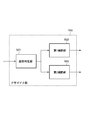
- FIG. 2 is a block diagram illustrating a functional configuration example of the imaging apparatus according to the first embodiment.
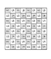
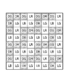
- FIG. 3 is a diagram illustrating an example of arrangement of a solid-state imaging element on an image sensor 103.
- requires DG value of each pixel.
- requires DG value of each pixel.
- requires DR value and RB value of each pixel.
- FIG. 3 is a diagram illustrating an example of arrangement of a solid-state imaging element on an image sensor 103.
- the A / D conversion unit 104 converts the analog image signal input from the image sensor 103 into a digital image signal, and outputs the converted digital image signal to the subsequent signal processing unit 105 and the media I / F 107.
- the signal processing unit 105 performs various image processing described later on the color image indicated by the digital image signal input from the A / D conversion unit 104. Then, the signal processing unit 105 outputs the image-processed color image to the display unit 106 and the media I / F 107 at the subsequent stage.
- the image sensor 103 includes a solid-state imaging element DR for imaging the R component with the first sensitivity, a solid-state imaging element DG for imaging the G component with the first sensitivity, and the first sensitivity.
- a solid-state image sensor DB for imaging the B component is two-dimensionally arranged.
- “DR” is dark red (first brightness red)
- “DG” is dark green (first brightness green)
- “DB” is dark blue (first brightness blue). Is shown.
- the image sensor 103 includes a solid-state imaging device LR for imaging the R component with a second sensitivity higher than the first sensitivity, a solid-state imaging device LG for imaging the G component with the second sensitivity,
- the solid-state imaging device LB for imaging the B component with the sensitivity of 2 is arranged two-dimensionally.
- “LR” is bright red (second brightness red that is brighter than the first brightness)
- “LG” is bright green (second brightness green)
- LB” is bright blue (second The brightness of blue).
- a 4 ⁇ 4 two-dimensional solid-state image sensor array composed of solid-state image sensors DR, DG, DB, LR, LG, and LB is repeatedly arranged in the image sensor 103 without overlapping. Furthermore, for each number of solid-state image sensors DR, DG, DB, LR, LG, and LB in one two-dimensional solid-state image sensor array, the ratio of the numbers of solid-state image sensors DR, DG, and DB is 1: 2: 1. The ratio of the numbers of the solid-state image sensors LR, LG, and LB is 1: 2: 1.
- a solid-state image sensor column (may be a solid-state image sensor row) including a solid-state image sensor DG and a solid-state image sensor LG is arranged on the image sensor 103 every other column (row).
- the arrangement positions of the solid-state imaging element LR and the solid-state imaging element LB can be interchanged.
- the arrangement positions of the solid-state imaging element DR and the solid-state imaging element DB can be interchanged.
- the imaging apparatus includes a solid-state imaging device for imaging a color component with a first sensitivity and an image for imaging a color component with a second sensitivity higher than the first sensitivity.
- An image sensor in which solid-state image sensors are alternately arranged two-dimensionally is mounted.
- the camera control unit 108 performs AE / AF / AWB control.
- the demosaic unit 109 performs interpolation processing on pixels imaged with the first sensitivity and interpolation processing on pixels imaged with the second sensitivity for the color image indicated by the digital image signal input from the A / D conversion unit 104. By doing so, an HDR image is generated.
- the color processing unit 111 performs various color processing such as color balance processing, ⁇ processing, sharpness processing, and noise reduction processing on the HDR image. Then, the color processing unit 111 outputs the HDR image subjected to the various color processings to the display unit 106 and the media I / F 107 at the subsequent stage.
- various color processing such as color balance processing, ⁇ processing, sharpness processing, and noise reduction processing on the HDR image. Then, the color processing unit 111 outputs the HDR image subjected to the various color processings to the display unit 106 and the media I / F 107 at the subsequent stage.
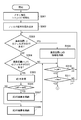
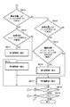
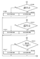
- FIGS. 3A and 3B showing a flowchart of the processing.
- the process performed by the demosaic unit 109 to obtain the DG value of each pixel constituting the color image is a process in which “DG” is replaced with “LG” in the flowcharts of FIGS. 3A and 3B.
- the demosaic unit 109 secures a memory area for performing processing described later in a memory that the demosaic unit 109 has or manages, and sets both the variables i and j indicating the pixel positions on the color image to 0. initialize.
- the variable i indicates the x coordinate value on the color image
- the variable j indicates the y coordinate value on the color image.
- the setting of the coordinate system on the color image is not limited to this.
- the demosaic unit 109 indicates which solid-state image sensor of DR, DG, DB, LR, LG, and LB is arranged at each position on the image sensor 103 as illustrated in FIG. Map information (filter array) is read from the memory.
- step S303 the demosaic unit 109 determines whether the solid-state image sensor at the position on the image sensor 103 corresponding to the pixel position (i, j) on the color image is the solid-state image sensor DG. To do. This means that it is determined whether or not the pixel at the pixel position (i, j) on the color image has been imaged by the solid-state imaging device DG. Such determination may be made by determining whether or not the solid-state imaging device at the position (i, j) on the image sensor 103 is the solid-state imaging device DG when the position of the upper left corner on the image sensor 103 is the origin.
- step S303 determines whether it is a solid-state image sensor DG. If the result of determination in step S303 is that it is a solid-state image sensor DG, the process proceeds to step S309, and if it is determined that it is not a solid-state image sensor DG, the process proceeds to step S304.
- step S304 the demosaic unit 109 maps whether or not the solid-state image sensor at the position on the image sensor 103 corresponding to the pixel position (i ⁇ 1, j ⁇ 1) on the color image is the solid-state image sensor DG. Judge using information. This determination is performed in the same manner as in step S303.
- step S304 determines whether it is a solid-state image sensor DG. If the result of determination in step S304 is that it is a solid-state image sensor DG, the process proceeds to step S305, and if it is determined that it is not a solid-state image sensor DG, the process proceeds to step S310.
- step S305 the demosaic unit 109 calculates the following Expression 1.
- the fluctuation evaluation value def2 for one pixel is obtained.
- P (i, j) indicates a pixel value at a pixel position (i, j) on the color image.
- step S306 the demosaic unit 109 compares def1 and diff2. As a result of the size comparison, if diff1 ⁇ diff2, the process proceeds to step S307, and if diff1 ⁇ defff2, the process proceeds to step S308.
- step S307 the demosaic unit 109 performs interpolation calculation using the pixel values of the peripheral pixels of the pixel at the pixel position (i, j), and thereby performs DG (i) indicating the DG value of the pixel at the pixel position (i, j). , J), the following equation 2 is calculated.
- This interpolation process is basically a one-dimensional low-pass filter process, and the coefficient value for each pixel value appearing in Equation 2 corresponds to a filter coefficient.
- the demosaic unit 109 performs interpolation calculation using the pixel values of the peripheral pixels of the pixel at the pixel position (i, j), thereby indicating the DG value of the pixel at the pixel position (i, j). In order to obtain (i, j), the following Equation 3 is calculated.
- step S309 the demosaic unit 109 substitutes the pixel value P (i, j) for DG (i, j).
- step S310 the demosaic unit 109 determines whether or not the value of the variable i is equal to pel (the total number of pixels in the x direction of the color image) -1. If it is determined that they are the same, the process proceeds to step S311. If it is determined that they are not the same, the value of the variable i is incremented by one, and the processes after step S303 are repeated.
- step S311 the demosaic unit 109 determines whether or not the value of the variable j is greater than line (total number of pixels in the y direction of the color image) -1. If j> line-1 is determined, the process proceeds to step S312, and if j ⁇ line-1 is determined, the value of variable i is initialized to 0 and the value of variable j is incremented by one. Then, the processing after step S303 is repeated.
- step S312 the demosaic unit 109 initializes variables i and j to 0.
- step S313 the demosaic unit 109 uses the solid-state image sensor DG as the solid-state image sensor DG at the position on the image sensor 103 corresponding to the pixel position (i ⁇ 1, j) or the pixel position (i, j ⁇ 1) on the color image. Whether or not there is is determined using the map information. This determination is performed in the same manner as in step S303.
- step S313 If the result of determination in step S313 is that it is a solid-state image sensor DG, the process proceeds to step S314, and if it is determined that it is not a solid-state image sensor DG, the process proceeds to step S318.
- step S314 the demosaic unit 109 calculates Equation 4 below, and the fluctuation evaluation value def3 for the upper and lower (y direction) pixels adjacent to the pixel Q at the pixel position (i, j), and the left and right (x direction) adjacent to the pixel Q. ) To obtain a variation evaluation value def4 for the pixel.
- step S315 the demosaic unit 109 compares def3 and diff4. As a result of this size comparison, if diff3 ⁇ diff4, the process proceeds to step S316. If diff3 ⁇ defff4, the process proceeds to step S317.
- step S316 the demosaic unit 109 performs interpolation calculation using the pixel values of the peripheral pixels of the pixel at the pixel position (i, j), and thereby performs DG (i) indicating the DG value of the pixel at the pixel position (i, j). , J), the following equation 5 is calculated.
- step S317 the demosaic unit 109 performs interpolation calculation using the pixel values of the peripheral pixels of the pixel at the pixel position (i, j), thereby indicating the DG value of the pixel at the pixel position (i, j).
- the following equation 6 is calculated.
- step S318 the demosaic unit 109 determines whether the value of the variable i is the same as pel-1. If it is determined that they are the same, the process proceeds to step S319. If it is determined that they are not the same, the value of the variable i is incremented by one, and the processes after step S313 are repeated.
- step S319 the demosaic unit 109 determines whether or not the value of the variable j is larger than line-1. If it is determined that j> line-1, the process is terminated, and the process proceeds to the process according to the flowcharts of FIGS. 4A and 4B. On the other hand, if it is determined that j ⁇ line ⁇ 1, the value of the variable i is initialized to 0, the value of the variable j is incremented by 1, and the processing from step S313 is repeated.
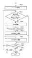
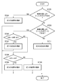
- FIGS. 4A and 4B showing a flowchart of the processing.
- the process performed by the demosaic unit 109 to obtain the LR value and the LB value of each pixel constituting the color image replaces “DR” with “LR” and “DB” with “LB” in the flowcharts of FIGS. 4A and 4B. "Is replaced with” ".
- the processing according to the flowcharts of FIGS. 4A and 4B is performed after the processing according to the flowcharts of FIGS. 3A and 3B (processing for DG and LG).
- step S401 the demosaic unit 109 secures a memory area for performing processing to be described later in a memory that the demosaic unit 109 has or manages, and sets both the variables i and j indicating the pixel position on the color image to 0. Initialize to.
- the demosaic unit 109 indicates which solid-state image sensor of DR, DG, DB, LR, LG, and LB is arranged at each position on the image sensor 103 as illustrated in FIG. Map information (filter array) is read from the memory.
- step S403 the demosaic unit 109 determines whether the solid-state image sensor at the position on the image sensor 103 corresponding to the pixel position (i, j) on the color image is the solid-state image sensor DG. To do. This determination is performed in the same manner as in the upper step S303.
- step S403 If the result of determination in step S403 is that it is a solid-state image sensor DG, the process proceeds to step S404, and if it is determined that it is not a solid-state image sensor DG, the process proceeds to step S407.
- step S404 the demosaic unit 109 determines whether or not the solid-state image sensor at the position on the image sensor 103 corresponding to the pixel position (i ⁇ 1, j) on the color image is the solid-state image sensor LB. Use to judge. This determination is performed in the same manner as in step S303.
- step S404 determines whether it is a solid-state image sensor LB. If the result of determination in step S404 is that it is a solid-state image sensor LB, the process proceeds to step S405, and if it is determined that it is not a solid-state image sensor LB, the process proceeds to step S406.
- step S405 the demosaic unit 109 performs the interpolation calculation shown in Expression 7. Thereby, DR (i, j) indicating the DR value of the pixel at the pixel position (i, j), DB (i, j) indicating the DB value, LR (i, j) indicating the LR value, and the LB value are indicated.
- LB (i, j) can be determined.
- step S406 the demosaic unit 109 performs the interpolation calculation shown in Expression 8. Thereby, DR (i, j), DB (i, j), LR (i, j), and LB (i, j) of the pixel at the pixel position (i, j) can be obtained.
- step S407 the demosaic unit 109 uses the map information to determine whether the solid-state image sensor at the position on the image sensor 103 corresponding to the pixel position (i, j) on the color image is the solid-state image sensor LR. to decide. This determination is performed in the same manner as in step S303.
- step S407 If the result of determination in step S407 is that it is a solid-state image sensor LR, the process proceeds to step S408, and if it is determined that it is not a solid-state image sensor LR, the process proceeds to step S409.
- step S408 the demosaic unit 109 performs the interpolation calculation shown in Equation 9. Thereby, DR (i, j), DB (i, j), LR (i, j), and LB (i, j) of the pixel at the pixel position (i, j) can be obtained.
- step S409 the demosaic unit 109 uses the map information to determine whether the solid-state image sensor at the position on the image sensor 103 corresponding to the pixel position (i, j) on the color image is the solid-state image sensor LB. to decide. This determination is performed in the same manner as in step S303.
- step S409 the process proceeds to step S410 if it is determined that it is a solid-state image sensor LB, and the process proceeds to step S411 if it is determined that it is not a solid-state image sensor LB.
- step S410 the demosaic unit 109 performs the interpolation calculation shown in Expression 10. Thereby, DR (i, j), DB (i, j), LR (i, j), and LB (i, j) of the pixel at the pixel position (i, j) can be obtained.
- step S411 the demosaic unit 109 uses the map information to determine whether the solid-state image sensor at the position on the image sensor 103 corresponding to the pixel position (i, j) on the color image is the solid-state image sensor LG. to decide. This determination is performed in the same manner as in step S303.
- step S411 if it is determined that the image sensor is a solid-state image sensor LG, the process proceeds to step S412. If it is determined that the image sensor is not a solid-state image sensor LG, the process proceeds to step S415.
- step S412 the demosaic unit 109 determines whether or not the solid-state image sensor at the position on the image sensor 103 corresponding to the pixel position (i ⁇ 1, j) on the color image is the solid-state image sensor DR. Use to judge. This determination is performed in the same manner as in step S303.
- step S412 determines whether it is a solid-state image sensor DR. If the result of determination in step S412 is that it is a solid-state image sensor DR, the process proceeds to step S413, and if it is determined that it is not a solid-state image sensor DR, the process proceeds to step S414.
- step S413 the demosaic unit 109 performs the interpolation calculation shown in Expression 11. Thereby, DR (i, j), DB (i, j), LR (i, j), and LB (i, j) of the pixel at the pixel position (i, j) can be obtained.
- step S414 the demosaic unit 109 performs the interpolation calculation shown in Expression 12. Thereby, DR (i, j), DB (i, j), LR (i, j), and LB (i, j) of the pixel at the pixel position (i, j) can be obtained.
- step S415 the demosaic unit 109 uses the map information to determine whether the solid-state image sensor at the position on the image sensor 103 corresponding to the pixel position (i, j) on the color image is the solid-state image sensor DR. to decide. This determination is performed in the same manner as in step S303.
- step S415 if it is determined that it is a solid-state image sensor DR, the process proceeds to step S416, and if it is determined that it is not a solid-state image sensor DR, that is, if it is determined that the solid-state image sensor DR The process proceeds to step S417.
- step S416 the demosaic unit 109 performs the interpolation calculation shown in Expression 13. Thereby, DR (i, j), DB (i, j), LR (i, j), and LB (i, j) of the pixel at the pixel position (i, j) can be obtained.
- step S417 the demosaic unit 109 performs the interpolation calculation shown in Expression 14. Thereby, DR (i, j), DB (i, j), LR (i, j), and LB (i, j) of the pixel at the pixel position (i, j) can be obtained.
- step S418 the demosaic unit 109 determines whether the value of the variable i is the same as pel-1. If it is determined that they are the same, the process proceeds to step S419. If it is determined that they are not the same, the value of the variable i is incremented by one and the processes in and after step S403 are repeated.
- step S419 the demosaic unit 109 determines whether the value of the variable j is larger than line-1. If j> line-1 is determined, the process is terminated. On the other hand, if it is determined that j ⁇ line ⁇ 1, the value of the variable i is initialized to 0, the value of the variable j is incremented by 1, and the processing from step S403 is repeated.
- the color components (DR, DG, DB, LR, LG, LB) for each pixel constituting the color image are obtained by performing the processing according to the flowcharts of FIGS. 3A, 3B, 4A, and 4B described above. It will be confirmed.
- the present embodiment is characterized in that this determination process is realized by the following calculation process. That is, the color component of the pixel imaged with the first sensitivity is obtained by interpolation calculation (first calculation) using the color component of the pixel imaged with the first sensitivity around the pixel. Then, the color component of the pixel imaged with the second sensitivity is obtained by interpolation calculation (second calculation) using the color component of the pixel imaged with the second sensitivity around the pixel.
- This embodiment is different from the first embodiment only in the configuration and operation of the demosaic unit 109 described above.
- the demosaic unit 109 according to the present embodiment has a configuration as shown in FIG.
- the saturation determination unit 501 determines whether the pixel value is saturated for each pixel constituting the color image. Then, the first interpolation unit 502 operates for pixels whose pixel values are saturated, and the second interpolation unit 503 operates for pixels whose pixel values are not saturated.
- the second interpolation unit 503 is the same as the operation of the demosaic unit 109 described in the first embodiment, the operation of the first interpolation unit 502 will be described below, and the operation of the second interpolation unit 503 will be described. Omitted. Moreover, in the following description, only the difference with 1st Embodiment is mentioned, and it is the same as 1st Embodiment except the point demonstrated below.
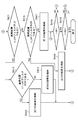
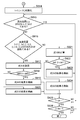
- FIGS. 6A and 6B showing a flowchart of the process.
- the pixel value P (i, j) is stored in advance in DG (i, j).
- step S601 the demosaic unit 109 secures a memory area for performing processing to be described later in a memory that the demosaic unit 109 has or manages, and sets both the variables i and j indicating the pixel position on the color image to 0. initialize.
- the demosaic unit 109 indicates which of the solid-state imaging elements DR, DG, DB, LR, LG, and LB is arranged at each position on the image sensor 103 as illustrated in FIG. Map information (filter array) is read from the memory.
- step S603 the demosaic unit 109 determines whether or not the solid-state image sensor at the position on the image sensor 103 corresponding to the pixel position (i, j) on the color image is the solid-state image sensor LG. To do. This determination is performed in the same manner as in step S303 described above.
- step S603 If the result of determination in step S603 is that it is a solid-state image sensor LG, the process proceeds to step S604, and if it is determined that it is not a solid-state image sensor LG, the process proceeds to step S607.
- step S604 the demosaic unit 109 determines whether or not the pixel value of the pixel at the pixel position (i, j) on the color image is saturated. As a result of such determination, if it is determined that it is saturated, the process proceeds to step S605, and if it is determined that it is not saturated, the process proceeds to step S606. Whether the pixel value is saturated is determined as follows. That is, if the pixel value is equal to or greater than a predetermined value, it is determined that the pixel is saturated, and if the pixel value is smaller than the predetermined value, it is determined that the pixel value is unsaturated.
- the “predetermined value” is not particularly limited, but here, for the sake of convenience, the description will be made assuming that the maximum value of the sensor analog value is used.
- step S607 the demosaic unit 109 determines whether the value of the variable i is the same as pel-1. If it is determined that they are the same, the process proceeds to step S608. If it is determined that they are not the same, the value of the variable i is incremented by one, and the processes after step S603 are repeated.
- step S608 the demosaic unit 109 determines whether the value of the variable j is larger than line-1. If j> line-1 is determined, the process proceeds to step S609. On the other hand, if it is determined that j ⁇ line ⁇ 1, the value of the variable i is initialized to 0, the value of the variable j is incremented by 1, and the processing from step S603 is repeated.
- step S609 the demosaic unit 109 initializes the values of the variables i and j to 0.
- step S610 the demosaic unit 109 maps whether the solid-state image sensor at the position on the image sensor 103 corresponding to the pixel position (i, j) on the color image is the solid-state image sensor DR or the solid-state image sensor DB. Judge using information. This determination is performed in the same manner as in step S303 described above.
- step S610 if it is determined that the solid-state imaging device DR or solid-state imaging device DB is used, the process proceeds to step S611. The process proceeds to step S614.
- step S611 the demosaic unit 109 determines whether the pixel value of the pixel at the pixel position (i ⁇ 1, j) or the pixel position (i + 1, j) on the color image is saturated. To do. As a result of the determination, if it is determined that it is saturated, the process proceeds to step S612. If it is determined that it is not saturated, the process proceeds to step S613.
- step S614 the demosaic unit 109 maps whether the solid-state image sensor at the position on the image sensor 103 corresponding to the pixel position (i, j) on the color image is the solid-state image sensor LR or the solid-state image sensor LB. Judge using information. This determination is performed in the same manner as in step S303 described above.
- step S614 the process proceeds to step S615 if it is determined that it is a solid-state image sensor LR or a solid-state image sensor LB, and if it is determined that neither the solid-state image sensor LR nor the solid-state image sensor LB is processed. The process proceeds to step S618.
- step S615 the demosaic unit 109 selects one of the pixel positions (i ⁇ 1, j ⁇ 1), (i ⁇ 1, j + 1), (i + 1, j ⁇ 1), and (i + 1, j + 1) on the color image. It is determined whether or not the pixel value of the pixel at the pixel position is saturated. As a result of such determination, if it is determined that it is saturated, the process proceeds to step S616, and if it is determined that it is not saturated, the process proceeds to step S617.
- step S618 the demosaic unit 109 determines whether the value of the variable i is the same as pel-1. If it is determined that they are the same, the process proceeds to step S619. If it is determined that they are not the same, the value of the variable i is incremented by one, and the processes in and after step S610 are repeated.
- step S619 the demosaic unit 109 determines whether the value of the variable j is larger than line-1. If j> line-1 is determined, the process is terminated. On the other hand, if it is determined that j ⁇ line ⁇ 1, the value of the variable i is initialized to 0, the value of the variable j is incremented by 1, and the processing from step S610 is repeated.
- step S703 the first interpolation unit 502 determines whether the solid-state image sensor at the position on the image sensor 103 corresponding to the pixel position (i, j) on the color image is the solid-state image sensor LG. Use to judge. This determination is performed in the same manner as in step S303 described above.
- step S704 the first interpolation unit 502 determines DG (i, j) by calculating Equation 15.
- step S705 the first interpolation unit 502 determines whether the solid-state image sensor at the position on the image sensor 103 corresponding to the pixel position (i, j) on the color image is the solid-state image sensor DR or the solid-state image sensor DB. Is determined using the map information. This determination is performed in the same manner as in step S303 described above.
- step S706 the first interpolation unit 502 calculates the following Expression 16.
- an evaluation value deff5-1 is an evaluation value for pixels adjacent to the upper left and lower right of the pixel position (i, j).
- the fluctuation evaluation value def6-1 is a fluctuation evaluation value for the left and right pixels adjacent to the pixel position (i, j).
- the evaluation value deff7-1 is an evaluation value for pixels adjacent to the lower left and upper right of the pixel position (i, j). If any one of the upper left and lower right combinations is saturated in the calculation of each evaluation value, the evaluation value diff5-2 is obtained instead of the evaluation value diff5-1. When either one of the left and right combinations is saturated, the evaluation value def6-2 is obtained instead of the evaluation value diff6-1. Further, when one of the combination of the lower left and upper right is saturated, the evaluation value def7-2 is obtained instead of the evaluation value diff7-1.
- MAX represents the difference between the minimum pixel value and the maximum pixel value, and is 255 when the pixel value is 8 bits and 65535 when the pixel value is 16 bits.
- step S706 the first interpolation unit 502 compares def5 with diff6 and def7. As a result of this size comparison, if the conditions of diff5 ⁇ defff6 and diff5 ⁇ defff7 are satisfied, the process proceeds to step S707, and if this condition is not satisfied, the process proceeds to step S708.
- step S ⁇ b> 707 the first interpolation unit 502 performs interpolation calculation using pixel values of pixels adjacent to the upper left and lower right of the pixel position (i, j), so that the DG of the pixel at the pixel position (i, j) ( In order to obtain i, j), the following equation 17 is calculated.
- step S708 the first interpolation unit 502 compares the above def6 and def7. As a result of this size comparison, if diff6 ⁇ def7, the process proceeds to step S709, and if diff6 ⁇ defff7, the process proceeds to step S710.
- step S709 the first interpolation unit 502 performs interpolation calculation using the pixel values of the left and right pixels adjacent to the pixel position (i, j), so that the DG (i, j) of the pixel at the pixel position (i, j) is obtained.
- the following equation 18 is calculated.
- step S710 the first interpolation unit 502 performs interpolation calculation using the pixel values of the pixels adjacent to the lower left and upper right of the pixel position (i, j), so that the DG of the pixel at the pixel position (i, j) ( In order to obtain i, j), the following equation 19 is calculated.
- step S711 the first interpolation unit 502 performs an interpolation calculation using pixel values of pixels adjacent to the left and right of the pixel position (i, j), so that the DG (i, j) of the pixel at the pixel position (i, j) is obtained.
- the following equation 20 is calculated.
- the solid-state imaging device arranged on the image sensor 103 preferably has the arrangement distribution shown in FIG. Moreover, in the following description, only the difference with 2nd Embodiment is touched and it is the same as 1st Embodiment except the point demonstrated below.
- FIGS. 8A and 8B showing a flowchart of the process.
- the pixel value P (i, j) is stored in advance in DG (i, j).
- step S801 the demosaic unit 109 secures a memory area for performing processing to be described later in a memory that the demosaic unit 109 has or manages, and sets both the variables i and j indicating the pixel positions on the color image to 0. initialize.
- the demosaic unit 109 indicates which solid-state imaging element of DR, DG, DB, LR, LG, and LB is arranged at each position on the image sensor 103 as illustrated in FIG. Map information (filter array) is read from the memory.
- step S803 the demosaic unit 109 determines whether the solid-state image sensor at the position on the image sensor 103 corresponding to the pixel position (i, j) on the color image is the solid-state image sensor DG. To do. This determination is performed in the same manner as in step S303 described above.
- step S803 If the result of determination in step S803 is that it is not a solid-state image sensor DG, the process proceeds to step S804, and if it is determined that it is a solid-state image sensor DG, the process proceeds to step S811.
- step S804 the demosaic unit 109 determines whether or not the solid-state image sensor at the position on the image sensor 103 corresponding to the pixel position (i, j) on the color image is the solid-state image sensor LG. To do. This determination is performed in the same manner as in step S303 described above.
- step S804 if it is determined that it is not a solid-state image sensor LG, the process proceeds to step S812, and if it is determined that it is a solid-state image sensor LG, the process proceeds to step S805.
- step S805 the demosaic unit 109 determines whether the pixel value of the pixel at the pixel position (i, j) on the color image is saturated. As a result of such determination, if it is determined that it is saturated, the process proceeds to step S806, and if it is determined that it is not saturated, the process proceeds to step S810.
- step S806 the first interpolation unit 502 calculates the following Expression 21.
- the evaluation value def8 for the pixels adjacent to the upper left and lower right of the pixel position (i, j) and the fluctuation evaluation value def9 for the pixels adjacent to the lower left and upper right of the pixel position (i, j) are obtained.
- step S807 def8 and diff9 are compared in size, and if diff8 ⁇ def9, the process proceeds to step S808, and if diff8 ⁇ defff9, the process proceeds to step S809.
- step S808 the first interpolation unit 502 performs interpolation calculation by calculating the following Expression 22. Thereby, the DG (i, j) of the pixel at the pixel position (i, j) can be obtained.
- step S809 the first interpolation unit 502 performs interpolation calculation by calculating the following Expression 23. Thereby, the DG (i, j) of the pixel at the pixel position (i, j) can be obtained.
- step S810 the first interpolation unit 502 performs interpolation calculation by calculating the following Expression 24. Thereby, the DG (i, j) of the pixel at the pixel position (i, j) can be obtained.
- step S811 the demosaic unit 109 substitutes the pixel value P (i, j) for DG (i, j).
- step S812 the demosaic unit 109 determines whether the value of the variable i is the same as pel-1. If it is determined that they are the same, the process proceeds to step S813. If it is determined that they are not the same, the value of the variable i is incremented by one, and the processes in and after step S803 are repeated.
- step S813 the demosaic unit 109 determines whether the value of the variable j is greater than line-1. If it is determined that j> line-1, the process proceeds to step S814. On the other hand, when it is determined that j ⁇ line ⁇ 1, the value of the variable i is initialized to 0, the value of the variable j is incremented by 1, and the processes after step S803 are repeated.
- step S813 the demosaic unit 109 initializes both the variables i and j to 0.
- step S814 the demosaic unit 109 determines whether the pixel position (i, j) is DG or LG. If it is determined that the pixel position (i, j) is DG or LG, the process proceeds to step S825. Proceeding to step S816 In step S816, the demosaic unit 109 selects one of the pixel positions (i ⁇ 2, j), (i + 2, j), (i, j), (i, j ⁇ 2), (i, j + 2). It is determined whether or not the solid-state imaging device at the position on the image sensor 103 corresponding to is saturated. This determination is made in the same manner as in step S805. If it is determined that it is saturated, the process proceeds to step S817. If it is determined that it is not saturated, the process proceeds to step S821.
- step S817 the first interpolation unit 502 calculates the following Expression 25. By this calculation, an evaluation value def10 for pixels adjacent to the pixel position (i, j) above and below, and a variation evaluation value def11 for the pixels adjacent to the pixel position (i, j) are obtained.
- step S818 the demosaic unit 109 compares def10 with def11. As a result of the size comparison, if diff10 ⁇ diff11, the process proceeds to step S819. If diff10 ⁇ defff11, the process proceeds to step S820.
- step S819 the first interpolation unit 502 performs interpolation calculation by calculating the following Expression 26. Thereby, DG (i, j) of the pixel at the pixel position (i, j) can be obtained.
- step S820 the first interpolation unit 502 performs interpolation calculation by calculating the following Expression 27. Thereby, DG (i, j) of the pixel at the pixel position (i, j) can be obtained.
- step S821 the second interpolation unit 503 calculates the following Expression 28. By this calculation, the evaluation value def12 for the pixel adjacent in the vertical direction of the pixel position (i, j) and the fluctuation evaluation value def13 for the pixel adjacent in the horizontal direction of the pixel position (i, j) are obtained.
- step S822 the demosaic unit 109 compares def12 and diff13 with each other. As a result of the size comparison, if diff12 ⁇ diff13, the process proceeds to step S823, and if diff12 ⁇ defff13, the process proceeds to step S824.
- step S823 the second interpolation unit 503 performs interpolation calculation by calculating the following Expression 29. Thereby, DG (i, j) of the pixel at the pixel position (i, j) can be obtained.
- step S824 the first interpolation unit 503 performs interpolation calculation by calculating the following Expression 30. Thereby, DG (i, j) of the pixel at the pixel position (i, j) can be obtained.
- step S825 the demosaic unit 109 determines whether the value of the variable i is the same as pel-1. If it is determined that they are the same, the process proceeds to step S826. If it is determined that they are not the same, the value of the variable i is incremented by one, and the processes after step S815 are repeated.
- step S826 the demosaic unit 109 determines whether the value of the variable j is larger than line-1. If j> line-1 is determined, the process is terminated. On the other hand, if it is determined that j ⁇ line ⁇ 1, the value of the variable i is initialized to 0, the value of the variable j is incremented by 1, and the processing from step S815 onward is repeated.
- step S1001 the demosaic unit 109 secures a memory area for performing processing to be described later in a memory that the demosaic unit 109 has or manages, and sets both the variables i and j indicating the pixel position on the color image to 0. initialize.
- the demosaic unit 109 indicates which solid-state image sensor of DR, DG, DB, LR, LG, and LB is arranged at each position on the image sensor 103 as illustrated in FIG. Map information (filter array) is read from the memory.
- step S1003 the demosaic unit 109 determines whether the solid-state image sensor at the position on the image sensor 103 corresponding to the pixel position (i, j) on the color image is the solid-state image sensor DG. To do. This determination is performed in the same manner as in step S303 described above. If the pixel position (i, j) is DG, the process proceeds to step S1004, and if it is not DG, the process proceeds to step S1007.
- step S1004 the demosaic unit 109 performs pixel detection at the pixel position (i ⁇ 1, j) or pixel position (i + 1, j), pixel position (i, j ⁇ 1), or pixel position (i, j + 1) on the color image. It is determined whether the pixel value of is saturated. As a result of such determination, if it is determined that it is saturated, the process proceeds to step S1005, and if it is determined that it is not saturated, the process proceeds to step S1006.
- step S1005 the first interpolation unit 502 performs interpolation calculation by calculating the following Expression 31. Thereby, DR (i, j) and DB (i, j) of the pixel at the pixel position (i, j) can be obtained.
- step S1006 the second interpolation unit 503 performs interpolation calculation by calculating the following Expression 32. Thereby, DR (i, j) and DB (i, j) of the pixel at the pixel position (i, j) can be obtained.
- step S1007 the demosaic unit 109 determines whether or not the solid-state image sensor at the position on the image sensor 103 corresponding to the pixel position (i, j) on the color image is the solid-state image sensor LR. To do. This determination is performed in the same manner as in step S303 described above. If the pixel position (i, j) is LR, the process proceeds to step S1008, and if it is not LR, the process proceeds to step S1011.
- step S1008 the demosaic unit 109 determines whether or not the pixel value of the pixel at the pixel position (i, j) on the color image is saturated. As a result of such determination, if it is determined that it is saturated, the process proceeds to step S1009, and if it is determined that it is not saturated, the process proceeds to step S1010.
- step S1009 the first interpolation unit 502 performs interpolation calculation by calculating the following Expression 33. Thereby, DR (i, j) and DB (i, j) of the pixel at the pixel position (i, j) can be obtained.
- step S1010 the second interpolation unit 503 performs interpolation calculation by calculating the following Expression 34. Thereby, DR (i, j) and DB (i, j) of the pixel at the pixel position (i, j) can be obtained.
- step S1011 the demosaic unit 109 determines whether or not the solid-state image sensor at the position on the image sensor 103 corresponding to the pixel position (i, j) on the color image is the solid-state image sensor LB. To do. This determination is performed in the same manner as in step S303 described above. If the pixel position (i, j) is LB, the process proceeds to step S1012. If not, the process proceeds to step S1015.
- step S1012 the demosaic unit 109 determines whether or not the pixel value of the pixel at the pixel position (i, j) on the color image is saturated. As a result of such determination, if it is determined that it is saturated, the process proceeds to step S1013, and if it is determined that it is not saturated, the process proceeds to step S1014.
- step S1013 the first interpolation unit 502 performs interpolation calculation by calculating the following Expression 35. Thereby, DR (i, j) and DB (i, j) of the pixel at the pixel position (i, j) can be obtained.
- step S1014 the second interpolation unit 503 performs interpolation calculation by calculating the following Expression 36. Thereby, DR (i, j) and DB (i, j) of the pixel at the pixel position (i, j) can be obtained.
- step S1015 the demosaic unit 109 determines whether or not the solid-state image sensor at the position on the image sensor 103 corresponding to the pixel position (i, j) on the color image is the solid-state image sensor LG. To do. This determination is performed in the same manner as in step S303 described above. If the pixel position (i, j) is LG, the process proceeds to step S1016, and if not, the process proceeds to step S1019.
- step S1016 the demosaic unit 109 determines the pixel position (i ⁇ 1, j) or pixel position (i + 1, j) or pixel position (i, j ⁇ 1) or pixel position (i, j + 1) on the color image. It is determined whether or not the pixel value is saturated. As a result of the determination, if it is determined that it is saturated, the process proceeds to step S1017, and if it is determined that it is not saturated, the process proceeds to step S1018.
- step S1017 the first interpolation unit 502 performs interpolation calculation by calculating the following Expression 37. Thereby, DR (i, j) and DB (i, j) of the pixel at the pixel position (i, j) can be obtained.
- step S1018 the second interpolation unit 503 performs interpolation calculation by calculating the following Expression 38. Thereby, DR (i, j) and DB (i, j) of the pixel at the pixel position (i, j) can be obtained.
- step S1019 the demosaic unit 109 determines whether the solid-state image sensor at the position on the image sensor 103 corresponding to the pixel position (i, j) on the color image is the solid-state image sensor DR using the map information. To do. This determination is performed in the same manner as in step S303 described above. If the pixel position (i, j) is DR, the process proceeds to step S1020, and if not, the process proceeds to step S1021.
- step S1020 the first interpolation unit 502 performs interpolation calculation by calculating the following Expression 39. Thereby, DR (i, j) and DB (i, j) of the pixel at the pixel position (i, j) can be obtained.
- step S1021 the first interpolation unit 502 performs interpolation calculation by calculating the following Expression 40. Thereby, DR (i, j) and DB (i, j) of the pixel at the pixel position (i, j) can be obtained.
- sampling is performed by complementing using a color filter having the highest resolution and the correlation between multiple colors. It is possible to partially restore the resolution of the part that cannot be performed.
- the present invention can also be realized by executing the following processing. That is, software (program) that realizes the functions of the above-described embodiments is supplied to a system or apparatus via a network or various storage media, and a computer (or CPU, MPU, or the like) of the system or apparatus reads the program. It is a process to be executed.
Landscapes
- Engineering & Computer Science (AREA)
- Multimedia (AREA)
- Signal Processing (AREA)
- Physics & Mathematics (AREA)
- Spectroscopy & Molecular Physics (AREA)
- Color Television Image Signal Generators (AREA)
- Studio Devices (AREA)
Priority Applications (1)
| Application Number | Priority Date | Filing Date | Title |
|---|---|---|---|
| US13/153,314 US8466993B2 (en) | 2010-01-20 | 2011-06-03 | Image sensing using solid-state image sensing elements |
Applications Claiming Priority (4)
| Application Number | Priority Date | Filing Date | Title |
|---|---|---|---|
| JP2010-010366 | 2010-01-20 | ||
| JP2010010366 | 2010-01-20 | ||
| JP2010-288556 | 2010-12-24 | ||
| JP2010288556A JP5503522B2 (ja) | 2010-01-20 | 2010-12-24 | 撮像装置、撮像装置の制御方法 |
Related Child Applications (1)
| Application Number | Title | Priority Date | Filing Date |
|---|---|---|---|
| US13/153,314 Continuation US8466993B2 (en) | 2010-01-20 | 2011-06-03 | Image sensing using solid-state image sensing elements |
Publications (1)
| Publication Number | Publication Date |
|---|---|
| WO2011089869A1 true WO2011089869A1 (ja) | 2011-07-28 |
Family
ID=44306672
Family Applications (1)
| Application Number | Title | Priority Date | Filing Date |
|---|---|---|---|
| PCT/JP2011/000128 Ceased WO2011089869A1 (ja) | 2010-01-20 | 2011-01-13 | 撮像装置、撮像装置の制御方法 |
Country Status (3)
| Country | Link |
|---|---|
| US (1) | US8466993B2 (OSRAM) |
| JP (1) | JP5503522B2 (OSRAM) |
| WO (1) | WO2011089869A1 (OSRAM) |
Families Citing this family (6)
| Publication number | Priority date | Publication date | Assignee | Title |
|---|---|---|---|---|
| CN102870405B (zh) * | 2011-03-09 | 2015-06-17 | 富士胶片株式会社 | 彩色成像元件 |
| US9160937B2 (en) * | 2011-08-30 | 2015-10-13 | Sharp Kabushika Kaisha | Signal processing apparatus and signal processing method, solid-state imaging apparatus, electronic information device, signal processing program, and computer readable storage medium |
| US20130128083A1 (en) * | 2011-11-23 | 2013-05-23 | Himax Imaging Limited | High dynamic range image sensing device and image sensing method and manufacturing method thereof |
| JP2015171039A (ja) | 2014-03-07 | 2015-09-28 | キヤノン株式会社 | 色処理装置およびその方法 |
| JP6512884B2 (ja) | 2015-03-20 | 2019-05-15 | キヤノン株式会社 | 色変換処理装置および色変換処理方法 |
| US9906676B2 (en) | 2015-03-26 | 2018-02-27 | Canon Kabushiki Kaisha | Image processing apparatus and image processing method |
Citations (3)
| Publication number | Priority date | Publication date | Assignee | Title |
|---|---|---|---|---|
| JPH11275373A (ja) * | 1998-03-19 | 1999-10-08 | Nikon Corp | 補間処理方法 |
| JP2003230158A (ja) * | 2002-02-01 | 2003-08-15 | Sony Corp | 画像処理装置および方法、プログラム、並びに記録媒体 |
| JP2004336469A (ja) * | 2003-05-08 | 2004-11-25 | Fuji Film Microdevices Co Ltd | 固体撮像素子、撮像装置、及び画像処理方法 |
Family Cites Families (15)
| Publication number | Priority date | Publication date | Assignee | Title |
|---|---|---|---|---|
| JPH09219824A (ja) * | 1996-02-09 | 1997-08-19 | Sony Corp | 固体撮像装置 |
| JP2000059687A (ja) * | 1998-08-05 | 2000-02-25 | Canon Inc | 撮像装置および撮像システム |
| EP1357760B1 (en) * | 2001-01-09 | 2011-11-09 | Sony Corporation | Image processing device and method |
| US7116338B2 (en) * | 2001-09-26 | 2006-10-03 | Canon Kabushiki Kaisha | Color information processing apparatus and method |
| JP2004103785A (ja) * | 2002-09-09 | 2004-04-02 | Fuji Film Microdevices Co Ltd | 固体撮像素子 |
| JP3970185B2 (ja) * | 2003-01-14 | 2007-09-05 | 富士フイルム株式会社 | 固体撮像素子及びデジタルカメラ |
| JP4500574B2 (ja) * | 2004-03-30 | 2010-07-14 | 富士フイルム株式会社 | 広ダイナミックレンジカラー固体撮像装置及びこの固体撮像装置を搭載したデジタルカメラ |
| JP4479457B2 (ja) * | 2004-05-27 | 2010-06-09 | ソニー株式会社 | 画像処理装置、および画像処理方法、並びにコンピュータ・プログラム |
| JP4317117B2 (ja) * | 2004-11-19 | 2009-08-19 | 富士フイルム株式会社 | 固体撮像装置および撮像方法 |
| JP2006253876A (ja) | 2005-03-09 | 2006-09-21 | Sony Corp | 物理量分布検知装置および物理量分布検知装置の駆動方法 |
| JP4241840B2 (ja) * | 2006-02-23 | 2009-03-18 | 富士フイルム株式会社 | 撮像装置 |
| JP4984981B2 (ja) * | 2007-03-08 | 2012-07-25 | ソニー株式会社 | 撮像方法および撮像装置並びに駆動装置 |
| JP2009060342A (ja) * | 2007-08-31 | 2009-03-19 | Fujifilm Corp | 撮像装置及びccd型固体撮像素子の駆動方法 |
| JP4448888B2 (ja) * | 2008-04-01 | 2010-04-14 | 富士フイルム株式会社 | 撮像装置及び撮像装置の信号処理方法 |
| JP5342969B2 (ja) * | 2009-09-10 | 2013-11-13 | 富士フイルム株式会社 | 撮像装置及び撮像方法 |
-
2010
- 2010-12-24 JP JP2010288556A patent/JP5503522B2/ja not_active Expired - Fee Related
-
2011
- 2011-01-13 WO PCT/JP2011/000128 patent/WO2011089869A1/ja not_active Ceased
- 2011-06-03 US US13/153,314 patent/US8466993B2/en not_active Expired - Fee Related
Patent Citations (3)
| Publication number | Priority date | Publication date | Assignee | Title |
|---|---|---|---|---|
| JPH11275373A (ja) * | 1998-03-19 | 1999-10-08 | Nikon Corp | 補間処理方法 |
| JP2003230158A (ja) * | 2002-02-01 | 2003-08-15 | Sony Corp | 画像処理装置および方法、プログラム、並びに記録媒体 |
| JP2004336469A (ja) * | 2003-05-08 | 2004-11-25 | Fuji Film Microdevices Co Ltd | 固体撮像素子、撮像装置、及び画像処理方法 |
Also Published As
| Publication number | Publication date |
|---|---|
| JP2011172211A (ja) | 2011-09-01 |
| US8466993B2 (en) | 2013-06-18 |
| US20110234844A1 (en) | 2011-09-29 |
| JP5503522B2 (ja) | 2014-05-28 |
Similar Documents
| Publication | Publication Date | Title |
|---|---|---|
| JP4900343B2 (ja) | ビデオ撮像装置および露光ガイド表示方法 | |
| JP5503522B2 (ja) | 撮像装置、撮像装置の制御方法 | |
| JP5603506B2 (ja) | 撮像装置及び画像処理方法 | |
| JP6372983B2 (ja) | 焦点検出装置およびその制御方法、撮像装置 | |
| JP2015220716A (ja) | 撮像素子、その制御方法、および制御プログラム、並びに信号処理装置 | |
| JP5474258B2 (ja) | 撮像装置及び撮像プログラム | |
| JP5943393B2 (ja) | 撮像装置 | |
| CN105578080A (zh) | 成像方法、图像传感器、成像装置及电子装置 | |
| JP2009164778A (ja) | 撮像装置 | |
| US8218021B2 (en) | Image capture apparatus, method of controlling the same, and program | |
| US8773543B2 (en) | Method and apparatus for image data transfer in digital photographing | |
| US10171782B2 (en) | Image sensor and method of generating restoration image | |
| JP3902525B2 (ja) | 画像信号処理装置 | |
| US20240430568A1 (en) | Imaging element including processor configured to receive vibration information related to a vibration exerted on the imaging element, imaging apparatus, operation method of imaging element, and program | |
| JP2015211347A (ja) | 画像処理装置、撮像装置、画像処理方法およびプログラム | |
| JP2013197613A (ja) | 撮像装置、画像処理装置及び画像処理プログラム | |
| JP2011151597A (ja) | 画像処理装置および画像処理プログラム並びに電子カメラ | |
| JP6856999B2 (ja) | 画像処理装置、画像処理方法及びプログラム | |
| JP2017204787A (ja) | 画像処理装置およびその制御方法、撮像装置、プログラム | |
| JP2016040870A (ja) | 画像処理装置、像形成方法およびプログラム | |
| JP4687619B2 (ja) | 画像処理装置、画像処理方法及びプログラム | |
| JP5513311B2 (ja) | 撮像モジュール、画像処理装置および画像信号処理方法 | |
| JP6390245B2 (ja) | 画像格納装置、画像管理方法及びプログラム | |
| JP6314281B1 (ja) | 画像処理方法及び前景領域取得方法 | |
| JP2017050700A (ja) | 画像処理装置、撮像装置および画像処理プログラム |
Legal Events
| Date | Code | Title | Description |
|---|---|---|---|
| 121 | Ep: the epo has been informed by wipo that ep was designated in this application |
Ref document number: 11734477 Country of ref document: EP Kind code of ref document: A1 |
|
| NENP | Non-entry into the national phase |
Ref country code: DE |
|
| 122 | Ep: pct application non-entry in european phase |
Ref document number: 11734477 Country of ref document: EP Kind code of ref document: A1 |