WO2011089797A1 - ロータ、これを用いた回転電機および発電機 - Google Patents
ロータ、これを用いた回転電機および発電機 Download PDFInfo
- Publication number
- WO2011089797A1 WO2011089797A1 PCT/JP2010/072347 JP2010072347W WO2011089797A1 WO 2011089797 A1 WO2011089797 A1 WO 2011089797A1 JP 2010072347 W JP2010072347 W JP 2010072347W WO 2011089797 A1 WO2011089797 A1 WO 2011089797A1
- Authority
- WO
- WIPO (PCT)
- Prior art keywords
- hole
- rotor
- laminated core
- holes
- conductor
- Prior art date
- Legal status (The legal status is an assumption and is not a legal conclusion. Google has not performed a legal analysis and makes no representation as to the accuracy of the status listed.)
- Ceased
Links
Images


Classifications
-
- H—ELECTRICITY
- H02—GENERATION; CONVERSION OR DISTRIBUTION OF ELECTRIC POWER
- H02K—DYNAMO-ELECTRIC MACHINES
- H02K1/00—Details of the magnetic circuit
- H02K1/06—Details of the magnetic circuit characterised by the shape, form or construction
- H02K1/22—Rotating parts of the magnetic circuit
- H02K1/27—Rotor cores with permanent magnets
- H02K1/2706—Inner rotors
- H02K1/272—Inner rotors the magnetisation axis of the magnets being perpendicular to the rotor axis
- H02K1/274—Inner rotors the magnetisation axis of the magnets being perpendicular to the rotor axis the rotor consisting of two or more circumferentially positioned magnets
- H02K1/2753—Inner rotors the magnetisation axis of the magnets being perpendicular to the rotor axis the rotor consisting of two or more circumferentially positioned magnets the rotor consisting of magnets or groups of magnets arranged with alternating polarity
- H02K1/276—Magnets embedded in the magnetic core, e.g. interior permanent magnets [IPM]
-
- H—ELECTRICITY
- H02—GENERATION; CONVERSION OR DISTRIBUTION OF ELECTRIC POWER
- H02K—DYNAMO-ELECTRIC MACHINES
- H02K1/00—Details of the magnetic circuit
- H02K1/06—Details of the magnetic circuit characterised by the shape, form or construction
- H02K1/22—Rotating parts of the magnetic circuit
- H02K1/223—Rotor cores with windings and permanent magnets
Definitions
- the present invention relates to a rotor, a rotating electric machine and a generator using the same.
- the present invention has been made in view of such problems, and a rotor that realizes an efficient rotating electrical machine and generator with relatively small use of magnets, and a rotating electrical machine and power generation using the same.
- the purpose is to provide a machine.
- the rotor of the present invention is a rotor comprising a cylindrical laminated core formed by laminating electromagnetic steel sheets, and a magnet provided inside the laminated core, wherein the laminated On the laminated surface of the core, the V-shaped hole is provided with a long first hole and a second hole that constitute a V-shaped hole arranged in a V shape with the apex portion facing the rotation axis.
- the V-shaped hole is provided with a long first hole and a second hole that constitute a V-shaped hole arranged in a V shape with the apex portion facing the rotation axis.
- the length of the first hole in the longitudinal direction is larger than the length of the second hole in the longitudinal direction.
- the rotor since the rotor includes the magnet and the nonmagnetic conductor, a small and high output motor can be realized.
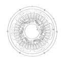
- a rotating electrical machine 10 includes a cylindrical rotor 20 and a cylindrical stator 30 that is provided outside the rotor and generates a rotating magnetic field.
- the rotor 20 includes a cylindrical laminated core 22 formed by laminating electromagnetic steel plates 21; It consists of a magnet 26 provided inside.
- the long first holes 20 a and the second holes 20 b constituting the V-shaped holes 23 arranged in a V shape with the apex portion 23 a facing the rotation center 20 e side. Is formed.
- a plurality of V-shaped holes 23 are arranged at a predetermined pitch in the circumferential direction. In the present embodiment, six V-shaped holes 23 are arranged at equal intervals at a pitch of 60 degrees.
- a dimension La in the longitudinal direction of the first hole 20a is formed larger than a dimension Lb in the longitudinal direction of the second hole 20b. Therefore, the V-shaped hole 23 can be rephrased as the L-shaped hole 23.
- a magnet 26 that is a permanent magnet is inserted into the first hole 20a, and a nonmagnetic conductor 27 made of aluminum is inserted into the second hole 20b.
- the dimension in the longitudinal direction of the magnet 26 is larger than the dimension in the longitudinal direction of the nonmagnetic conductor 27 in accordance with the dimension of the hole.
- End rings 29 as end members covering the laminated core 22 are attached to both ends of the laminated core 22 in the lamination direction.
- a third hole 20c and a fourth hole 20d are formed between the adjacent L-shaped holes 23.
- the third hole 20c and the fourth hole 20d are nonmagnetic and formed of aluminum.
- the second conductor 28 is inserted.
- Both the conductor 27 and the end rings 29 at both ends are made of aluminum, and these are integrally formed by aluminum die casting.
- the second conductor 28 and the end rings 29 at both ends are also formed of aluminum, and these are also integrally formed by aluminum die casting.
- An insertion hole 29a for inserting the magnet 26 is formed in at least one end ring 29 at both ends of the laminated core 22, and even after heat treatment (for example, after die casting), lamination is performed via the insertion hole 29a.
- a magnet 26 can be attached to the core 22.
- the stator 30 is provided with a plurality (36 in this embodiment) of teeth 31 that surround the rotor 20 at a predetermined pitch. On the stator 30 side between the adjacent L-shaped holes 23, there are a plurality of teeth 31 (two in this embodiment) between the end of the first hole 20a and the end of the second hole 20b adjacent thereto. ) It is supposed to exist. A winding 32 is wound around the stator 30.
- an eddy current is generated on the surfaces (aluminum surfaces) of the nonmagnetic conductor 27 and the conductor 28 of the rotor 20 by passing an alternating current through the winding 32 so as to rotate in the direction of arrow B. Since the eddy current has a function of preventing the winding magnetic flux from passing through, it is possible to prevent the winding magnetic flux from leaking to the adjacent pole. On the other hand, the magnetic flux can be prevented from leaking to the adjacent poles depending on the width and thickness of the conductors 27 and 28, so that the "L" -shaped portion sequentially forms independent S and N poles. be able to.
- the alternating magnetic flux of the winding 32 flows separately to the inside and outside of each “L” shape, and coil torque is obtained.
- an attractive force (gap magnetic flux +) is generated between the magnetic flux of the winding 32 and the magnetic flux of the magnet 26 in the direction where the aluminum 27 is inserted in the “L” shape.
- a repulsive force zero air gap magnetic flux
- a reluctance torque is obtained by the pulling force in the direction of arrow B.
- the magnet 26 is inserted into one hole and the nonmagnetic conductor 27 is inserted into the other hole, and the longitudinal dimension of the magnet 26 is nonmagnetic. Since it is larger than the dimension of the conductor 27 in the longitudinal direction, a certain amount of magnetic force can be secured in a limited area, and an effect of preventing magnetic flux leakage due to eddy current can be efficiently obtained. Accordingly, it is possible to provide a rotor that realizes an efficient rotating electrical machine that uses a relatively small amount of magnets, and a rotating electrical machine using the rotor.
- the non-magnetic second conductor 28 is provided between the adjacent L-shaped holes 23, the flow of the q-axis magnetic flux of the permanent magnet type rotating electric machine is directed, so that the q-axis convex pole is clearly defined. Thus, the pole can be reliably detected in the sensorless control.
- both ends of the laminated core 22 in the lamination direction are sandwiched between end rings 29 and are integrally formed by die-casting via the conductor 27 or the second conductor 28, the rotor 20 becomes very strong. ing. Furthermore, it is possible to balance the rotor with an end ring.
- An eddy current is generated on the aluminum surface by passing an alternating current through the winding, but it prevents the magnetic flux from leaking to the adjacent pole because the current acts to prevent the magnetic flux from passing. be able to.
- the d-axis and the q-axis of the permanent magnet type synchronous electric machine are separated, and the q-axis magnetic path between the rotor poles is directed to the teeth side of the two stators. Is obtained.
- the sensorless control is performed by capturing the convex pole of the rotating electric machine, but it is advantageous in terms of control if the convex pole is clear.
- the inserted non-magnetic aluminum as a non-magnetic conductor has the effect that a secondary current flows and generates rotational torque, and forms a magnetic path of a permanent magnet type synchronous electric machine and an induction electric machine at the same time, so that the magnetic flux can be rotated neatly. Therefore, a small and high output motor can be realized. Further, since the rotor is solidified by die casting and at the same time the rotor is balanced by the end ring as the end member, it is not necessary to provide a separate balance seat as in a normal permanent magnet type synchronous electric machine.
- the permanent magnet type synchronous electric machine is established. Only the third hole 20c may be provided. Moreover, it is not necessary to integrally mold the end ring 29 by die casting, and each end ring 29 may be attached to the laminated core 22 by fastening with a fastening means such as a bolt or by welding.
- a fastening means such as a bolt or by welding.
- the conductor 27, the second conductor 28, and the end ring 29 are all formed of aluminum is shown, it is not limited thereto, and any one or all of them are formed of copper, silver, or the like. May be.
- the example which applied the rotor of this invention to the rotary electric machine was shown, you may apply to a generator.
Landscapes
- Engineering & Computer Science (AREA)
- Power Engineering (AREA)
- Iron Core Of Rotating Electric Machines (AREA)
- Permanent Field Magnets Of Synchronous Machinery (AREA)
Abstract
Description
まず、図1から図3を参照しつつ、本発明の第1実施形態に係るロータおよびこれを用いた回転電機の構成について説明する。
この内部に設けられた磁石26とからなっている。積層コア22の積層面には、頂点部23aを回転中心20e側に向けてV字状に配置されたV字状穴23を構成する長尺状の第1の穴20aおよび第2の穴20bが形成されている。V字状穴23は、周方向に所定のピッチで複数配列されており、本実施形態においては、6個のV字状穴23が60度ピッチで等間隔に配列されている。
第1の穴20aには永久磁石である磁石26が挿入され、かつ、第2の穴20bには、アルミニウムで形成された非磁性の導電体27が挿入されている。積層コア22の積層面において、穴の寸法に対応して、磁石26の長手方向の寸法は、非磁性の導電体27の長手方向の寸法よりも大きくなっている。
第2の導電体28および両端のエンドリング29も、ともにアルミニウムで形成されており、これらもアルミニウムのダイキャストで一体成型されている。
積層コア22の両端の少なくとも一方のエンドリング29には、磁石26を挿入する挿入穴29aが形成されており、熱処理後(例えば、ダイキャスト後)であっても、挿入穴29aを介して積層コア22に磁石26を装着できるようになっている。
巻線に交流電流を流すことによりアルミ表面に渦電流が発生するが、その電流には磁束が通るのを妨げようとする働きがあるので、巻線磁束が隣の極に漏れるのを防止することができる。これにより、永久磁石型同期電機のd軸とq軸は分離され、ロータの極と極の間のq軸磁路を2つのステータのティース側に指向することになり、明確な磁気的凸極が得られる。ここで、センサレス制御は、回転電機の凸極を捕まえて制御するが、凸極が明確であると制御上好都合である。
また挿入された非磁性の導電体としてのアルミニウムには2次電流が流れ、回転トルクを発生するという効果があり、永久磁石型同期電機と誘導電機の磁路を同時に形成し、磁束がきれいに廻るので、小型で高出力のモータを実現できる。
また、ダイキャストによりロータが強固なものになると同時に端部部材としてのエンドリングでロータバランスを取れるので、通常の永久磁石型同期電機のように、別途バランス座を設ける必要はない。
また、導電体27、第2の導電体28およびエンドリング29をともにアルミニウムで形成した例を示したが、これに限られるものではなく、いずれか一つまたは全てを銅、銀などで形成してもよい。
さらに、本発明のロータを回転電機に適用した例を示したが、発電機に適用してもよい。
20 ロータ
22 積層コア
23 V字状穴(L字状穴)
26 磁石
27 導電体
30 ステータ
Claims (8)
- 電磁鋼板を積層して形成された円筒状の積層コアと、
前記積層コアの内部に設けられた磁石と、
からなるロータであって、
前記積層コアの積層面において、
頂点部を回転軸側に向けてV字状に配置されたV字状穴を構成する長尺状の第1の穴および第2の穴を備え、
前記V字状穴は、周方向に所定のピッチで複数配列されており、
前記第1の穴の長手方向の寸法は、前記第2の穴の長手方向の寸法よりも大きく形成されており、
前記第1の穴には前記磁石が挿入され、かつ、前記第2の穴には非磁性の導電体が挿入されている
ことを特徴とするロータ。 - 前記積層コアの積層方向両端には、当該積層コアを覆う端部部材が装着されており、
前記導電体と前記端部部材とが同一材料からなることを特徴とする請求項1記載のロータ。 - 前記端部部材に前記磁石が挿入される挿入穴を備えたことを特徴とする請求項2記載のロータ。
- 隣接する前記V字状穴間に、非磁性の第2の導電体を備えたことを特徴とする請求項2記載のロータ。
- 前記導電体および前記端部部材が、アルミニウムのダイキャストで一体成型されていることを特徴とする請求項2記載のロータ。
- 前記第2の導電体および前記端部部材が、アルミニウムのダイキャストで一体成型されていることを特徴とする請求項4記載のロータ。
- 請求項1記載のロータと、前記ロータを所定のピッチで取り囲むティースを有するステータとからなる回転電機であって、
隣接する前記V字状穴間の前記ステータ側において、前記第1の穴の端部とこれと隣接する前記第2の穴の端部との間に前記ティースが複数存在することを特徴とする回転電機。 - 請求項1記載のロータと、前記ロータを所定のピッチで取り囲むティースを有するステータとからなる発電機であって、
隣接する前記V字状穴間の前記ステータ側において、前記第1の穴の端部とこれと隣接する前記第2の穴の端部との間に前記ティースが複数存在することを特徴とする発電機。
Priority Applications (2)
| Application Number | Priority Date | Filing Date | Title |
|---|---|---|---|
| JP2011550807A JP5582149B2 (ja) | 2010-01-19 | 2010-12-13 | ロータ、これを用いた回転電機および発電機 |
| CN201080056761.9A CN102656773B (zh) | 2010-01-19 | 2010-12-13 | 转子、使用有该转子的旋转电机及发电机 |
Applications Claiming Priority (2)
| Application Number | Priority Date | Filing Date | Title |
|---|---|---|---|
| JP2010-009503 | 2010-01-19 | ||
| JP2010009503 | 2010-01-19 |
Publications (1)
| Publication Number | Publication Date |
|---|---|
| WO2011089797A1 true WO2011089797A1 (ja) | 2011-07-28 |
Family
ID=44306614
Family Applications (1)
| Application Number | Title | Priority Date | Filing Date |
|---|---|---|---|
| PCT/JP2010/072347 Ceased WO2011089797A1 (ja) | 2010-01-19 | 2010-12-13 | ロータ、これを用いた回転電機および発電機 |
Country Status (3)
| Country | Link |
|---|---|
| JP (1) | JP5582149B2 (ja) |
| CN (1) | CN102656773B (ja) |
| WO (1) | WO2011089797A1 (ja) |
Cited By (4)
| Publication number | Priority date | Publication date | Assignee | Title |
|---|---|---|---|---|
| CN103001434A (zh) * | 2011-09-15 | 2013-03-27 | 上海电驱动有限公司 | 增磁型凸极式混合励磁同步电机 |
| JP2013121284A (ja) * | 2011-12-08 | 2013-06-17 | Toyota Motor Corp | 電動機のロータおよびその製造方法 |
| CN103166344A (zh) * | 2011-12-09 | 2013-06-19 | 安徽明腾永磁机电设备有限公司 | 一种用于永磁电机的转子冲片和转子 |
| CN104115369A (zh) * | 2012-05-28 | 2014-10-22 | 株式会社日立产机系统 | 复合转矩型旋转电机 |
Citations (8)
| Publication number | Priority date | Publication date | Assignee | Title |
|---|---|---|---|---|
| JPH06245419A (ja) * | 1993-02-10 | 1994-09-02 | Honda Motor Co Ltd | 電動機又は発電機のヨーク |
| JPH0833246A (ja) * | 1994-07-20 | 1996-02-02 | Yaskawa Electric Corp | 永久磁石形同期回転電機のロータ |
| JP2001112202A (ja) * | 1996-09-13 | 2001-04-20 | Hitachi Ltd | 永久磁石回転電機およびそれを用いた電動車両 |
| JP2002171702A (ja) * | 2000-12-05 | 2002-06-14 | Isuzu Motors Ltd | 回転機のロータ |
| JP2003309953A (ja) * | 2002-04-15 | 2003-10-31 | Denso Corp | インナーロータ型回転電機の永久磁石ロータ |
| JP2004260920A (ja) * | 2003-02-26 | 2004-09-16 | Toyota Motor Corp | 回転子およびそれを含む電動機 |
| JP2008245439A (ja) * | 2007-03-28 | 2008-10-09 | Hitachi Appliances Inc | 電動機及びそれを用いた圧縮機 |
| JP2009296882A (ja) * | 2009-09-17 | 2009-12-17 | Yaskawa Electric Corp | 永久磁石形同期回転電機、それを備える車両、昇降機、流体機械および加工機 |
Family Cites Families (1)
| Publication number | Priority date | Publication date | Assignee | Title |
|---|---|---|---|---|
| CN2904438Y (zh) * | 2006-04-29 | 2007-05-23 | 刘洪预 | 永磁电机的全铸铝永磁转子 |
-
2010
- 2010-12-13 CN CN201080056761.9A patent/CN102656773B/zh not_active Expired - Fee Related
- 2010-12-13 JP JP2011550807A patent/JP5582149B2/ja not_active Expired - Fee Related
- 2010-12-13 WO PCT/JP2010/072347 patent/WO2011089797A1/ja not_active Ceased
Patent Citations (8)
| Publication number | Priority date | Publication date | Assignee | Title |
|---|---|---|---|---|
| JPH06245419A (ja) * | 1993-02-10 | 1994-09-02 | Honda Motor Co Ltd | 電動機又は発電機のヨーク |
| JPH0833246A (ja) * | 1994-07-20 | 1996-02-02 | Yaskawa Electric Corp | 永久磁石形同期回転電機のロータ |
| JP2001112202A (ja) * | 1996-09-13 | 2001-04-20 | Hitachi Ltd | 永久磁石回転電機およびそれを用いた電動車両 |
| JP2002171702A (ja) * | 2000-12-05 | 2002-06-14 | Isuzu Motors Ltd | 回転機のロータ |
| JP2003309953A (ja) * | 2002-04-15 | 2003-10-31 | Denso Corp | インナーロータ型回転電機の永久磁石ロータ |
| JP2004260920A (ja) * | 2003-02-26 | 2004-09-16 | Toyota Motor Corp | 回転子およびそれを含む電動機 |
| JP2008245439A (ja) * | 2007-03-28 | 2008-10-09 | Hitachi Appliances Inc | 電動機及びそれを用いた圧縮機 |
| JP2009296882A (ja) * | 2009-09-17 | 2009-12-17 | Yaskawa Electric Corp | 永久磁石形同期回転電機、それを備える車両、昇降機、流体機械および加工機 |
Cited By (5)
| Publication number | Priority date | Publication date | Assignee | Title |
|---|---|---|---|---|
| CN103001434A (zh) * | 2011-09-15 | 2013-03-27 | 上海电驱动有限公司 | 增磁型凸极式混合励磁同步电机 |
| JP2013121284A (ja) * | 2011-12-08 | 2013-06-17 | Toyota Motor Corp | 電動機のロータおよびその製造方法 |
| CN103166344A (zh) * | 2011-12-09 | 2013-06-19 | 安徽明腾永磁机电设备有限公司 | 一种用于永磁电机的转子冲片和转子 |
| CN104115369A (zh) * | 2012-05-28 | 2014-10-22 | 株式会社日立产机系统 | 复合转矩型旋转电机 |
| CN104115369B (zh) * | 2012-05-28 | 2016-11-30 | 株式会社日立产机系统 | 复合转矩型旋转电机 |
Also Published As
| Publication number | Publication date |
|---|---|
| JP5582149B2 (ja) | 2014-09-03 |
| CN102656773A (zh) | 2012-09-05 |
| JPWO2011089797A1 (ja) | 2013-05-23 |
| CN102656773B (zh) | 2014-09-17 |
Similar Documents
| Publication | Publication Date | Title |
|---|---|---|
| JP5774081B2 (ja) | 回転電機 | |
| JP4926107B2 (ja) | 回転電機 | |
| CN101026317B (zh) | 电力机械 | |
| JP5682600B2 (ja) | 回転電機のロータ | |
| EP3534496B1 (en) | Permanent magnet motor | |
| US8987967B2 (en) | Claw-pole motor with permanent magnet and electrically exciting parts | |
| EP2448089A1 (en) | Axial motor | |
| US7902700B1 (en) | Low harmonic loss brushless motor | |
| US20110316368A1 (en) | Electrical Machine | |
| CN103872868A (zh) | 多间隙式旋转电机 | |
| CN104380576B (zh) | 旋转电机的定子 | |
| US20110163618A1 (en) | Rotating Electrical Machine | |
| US9362790B2 (en) | Permanent magnet embedded rotor | |
| JP2009136046A (ja) | トロイダル巻式回転電機 | |
| JP6048191B2 (ja) | マルチギャップ型回転電機 | |
| CN103250326A (zh) | 电机和用于该电机的定子 | |
| JP4580683B2 (ja) | 永久磁石式リラクタンス型回転電機 | |
| JP5582149B2 (ja) | ロータ、これを用いた回転電機および発電機 | |
| US8987971B2 (en) | Rotor core for an electric machine | |
| JP2013132124A (ja) | 界磁子用コア | |
| JP2014082838A (ja) | 車両用電動機および車両用発電機 | |
| US11349358B2 (en) | Apparatus and method for an interior permanent magnet with rotor hybridization | |
| US9755465B2 (en) | Method for manufacturing a rotor of a synchronous reluctance motor, a rotor of a synchronous reluctance motor, and a synchronous reluctance motor | |
| US10574103B2 (en) | Interior magnet rotary electric machine | |
| JP2018148675A (ja) | 回転電機のステータ |
Legal Events
| Date | Code | Title | Description |
|---|---|---|---|
| WWE | Wipo information: entry into national phase |
Ref document number: 201080056761.9 Country of ref document: CN |
|
| 121 | Ep: the epo has been informed by wipo that ep was designated in this application |
Ref document number: 10843961 Country of ref document: EP Kind code of ref document: A1 |
|
| WWE | Wipo information: entry into national phase |
Ref document number: 2011550807 Country of ref document: JP |
|
| NENP | Non-entry into the national phase |
Ref country code: DE |
|
| 122 | Ep: pct application non-entry in european phase |
Ref document number: 10843961 Country of ref document: EP Kind code of ref document: A1 |