WO2011086726A1 - 振動型電磁発電機 - Google Patents
振動型電磁発電機 Download PDFInfo
- Publication number
- WO2011086726A1 WO2011086726A1 PCT/JP2010/064624 JP2010064624W WO2011086726A1 WO 2011086726 A1 WO2011086726 A1 WO 2011086726A1 JP 2010064624 W JP2010064624 W JP 2010064624W WO 2011086726 A1 WO2011086726 A1 WO 2011086726A1
- Authority
- WO
- WIPO (PCT)
- Prior art keywords
- magnet
- vibration type
- pipe
- type electromagnetic
- electromagnetic generator
- Prior art date
- Legal status (The legal status is an assumption and is not a legal conclusion. Google has not performed a legal analysis and makes no representation as to the accuracy of the status listed.)
- Ceased
Links
Images


Classifications
-
- H—ELECTRICITY
- H02—GENERATION; CONVERSION OR DISTRIBUTION OF ELECTRIC POWER
- H02K—DYNAMO-ELECTRIC MACHINES
- H02K35/00—Generators with reciprocating, oscillating or vibrating coil system, magnet, armature or other part of the magnetic circuit
- H02K35/02—Generators with reciprocating, oscillating or vibrating coil system, magnet, armature or other part of the magnetic circuit with moving magnets and stationary coil systems
Definitions
- the present invention relates to a vibration type electromagnetic wave that generates power by moving or moving a movable magnet including a plurality of magnets magnetized in the length direction in a power generation coil constituted by one or more solenoid coils.
- generators Regarding generators.
- Patent Document 1 discloses a vibration type electromagnetic generator that generates electric power by vibration applied from the outside.
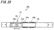
- FIG. 23 shows a configuration example of the vibration type electromagnetic generator 100.
- the vibration electromagnetic generator 100 includes a hollow pipe 105, two solenoid coils 104 a and 104 b wound around the pipe 105, and a movable magnet 101 that can move inside the pipe 105.
- the movable magnet 101 includes two magnets 102a and 102b.
- the magnets 102a and 102b are bonded to each other with the same poles facing each other through a non-magnetic spacer 103.
- the movable magnet 101 When vibration is applied to the vibration type electromagnetic generator 100, the movable magnet 101 reciprocally vibrates in the direction of the winding axis of the solenoid coils 104a and 104b to generate power.
- the solenoid coil may be simply abbreviated as “coil”.
- the conventional vibration type electromagnetic generator 100 has an advantage of high power generation efficiency while being small.
- a magnet having a large energy product such as an Nd (neodymium) magnet.
- Nd neodymium
- an electromotive force is generated in the coil by reciprocating a plurality of magnets facing the same polarity in a plurality of adjacent coils.
- the present invention has been made in view of such a situation, and an object thereof is to provide a vibration type electromagnetic generator having a high electromotive force while having a simple configuration and being easily assembled.
- the vibration type electromagnetic generator includes a hollow first pipe formed of a nonmagnetic material and closed at both ends, wound around the first pipe, and provided with at least one solenoid coil. And a movable magnet that is disposed inside the first pipe and is movable along the winding axis direction of the power generation coil.
- the movable magnet includes a plurality of magnets and a magnet fixing portion made of a non-magnetic material that fixes the plurality of magnets facing the same pole.
- the coil length of one or more solenoid coils is made into the length more than the magnet length of a magnet among several solenoid coils.
- the present invention by setting the coil length of one or more solenoid coils to be longer than the magnet length of the magnet, the range in which the magnetic field generated by the magnet passes through the solenoid coil is expanded, and the solenoid coil outputs.
- the voltage phase can be adjusted. For this reason, there exists an effect that the output voltage of a vibration type electromagnetic generator can be raised.
- the configuration of the vibration type electromagnetic generator is extremely simple, assembly is facilitated.
- FIGS. 1 a vibration type electromagnetic generator 1 that generates power by vibrating or moving a plurality of cylindrical magnets magnetized in the length direction in a plurality of solenoid coils. is there.
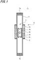
- FIG. 1 is a cross-sectional view showing a configuration example of the vibration type electromagnetic generator 1 of this example.
- the vibration type electromagnetic generator 1 includes a movable magnet 3 disposed so as to be movable in the first pipe 2 and solenoid coils 4a to 4c.
- the solenoid coils 4a to 4c are wound around the outer periphery of the hollow first pipe 2.
- the first pipe 2 is made of a nonmagnetic material.
- the material of the first pipe 2 may be a non-magnetic material such as a metal, but it is preferable to manufacture the first pipe 2 from a synthetic resin such as plastic in consideration of workability and the like.
- the solenoid coils 4a to 4c When the movable magnet 3 linearly reciprocates (hereinafter also simply referred to as vibration) inside the first pipe 2, the solenoid coils 4a to 4c generate voltages.
- the movable magnet 3 includes a hollow second pipe 5 formed of a nonmagnetic material, and a plurality of magnets (for example, neodymium magnets) having the same polarity opposed to each other are joined inside the second pipe 5. ) Is sealed. Magnets 3a and 3b of the same length magnetized in the length direction are integrally joined with the same poles facing each other. However, you may join between the magnets 3a and 3b via a spacer using either a magnetic body or a non-magnetic body.
- the movable magnet 3 preferably includes a plurality of magnets. The magnets 3 a and 3 b are sealed inside the second pipe 5 by caulking processing applied to both ends of the second pipe 5 while being inserted into the second pipe 5. For this reason, the 2nd pipe 5 is used as a magnet fixing
- Friction is generated when the movable magnet 3 vibrates and is caused by an increase in the number of contact points and the number of collisions between the inner wall surface of the first pipe 2 and the movable magnet 3, and a factor that attenuates the vibration of the movable magnet 3. It can be.
- a material having a low friction coefficient such as polypropylene (PP) for at least one or both of the first pipe 2 and the second pipe 5.
- PP polypropylene
- the solenoid coils 4a to 4c are a plurality of coils connected in series with opposite polarities, and are wound around the first pipe 2 at a predetermined interval.
- the winding directions of the solenoid coils are forward, reverse, and forward directions that are opposite to each other for each adjacent solenoid coil.
- the solenoid coils 4a to 4c connected in series are referred to as a power generating coil 9.
- the first pipe 2 is provided with at least one solenoid coil as the power generation coil 9.
- both end portions of the first pipe 2 are fitted with end members 7a and 7b formed of resin or the like, and both end portions of the first pipe 2 are formed by the end members 7a and 7b. Is closed.
- the end members 7a and 7b have the same shape, but these end members may have different shapes.
- the movable magnet 3 can vibrate in the winding axis direction of the power generation coil 9.
- the movable magnet 3 vibrates in the power generating coil 9, and a voltage is induced in the solenoid coils 4a to 4c, thereby generating an electromotive force.
- the voltage output from the vibration type electromagnetic generator 1 is increased by synthesizing the phases of the voltages generated by the solenoid coils 4a to 4c. For this purpose, it is necessary to adjust the magnet length and the coil length, or adjust the magnet length and the length obtained by adding the coil interval to the coil length.
- the coil length or the length obtained by adding the coil interval to the coil length is also referred to as “coil pitch”.
- the coil length of one or more solenoid coils among the plurality of solenoid coils 4a to 4c provided in the vibration type electromagnetic generator 1 is set to be longer than the magnet length of the magnet. The conditions for the magnet length and the coil pitch will be described later.
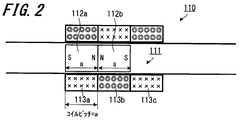
- FIG. 2 shows a configuration example of a conventional vibration type electromagnetic generator 110 having three solenoid coils and two magnets.
- the vibration type electromagnetic generator 110 having such a configuration is also referred to as “Comparative Example 1”.
- the conventional vibration type electromagnetic generator 110 includes a movable magnet 111 composed of two magnets 112a and 112b connected to each other, and three solenoid coils 113a to 113c.
- the length L in the winding axis direction of each solenoid coil 113a to 113c is equal to the length a in the major axis direction of the magnets 112a and 112b.
- the magnets 112a and 112b and the solenoid coils 113a to 113c have the following configuration.
- a magnet unit is configured by adhering a plurality of magnets with the same poles facing each other with no gaps. (Magnetization is in the major axis direction of the magnet.)
- a plurality of coils are configured by reversing the winding direction of adjacent coils, matching the coil axes, and electrically connected in series.
- the major axis dimension of one magnet is made equal to the coil pitch in the winding axis direction of the plurality of coils.
- the magnets and coils are configured according to the above conditions (1) to (3), so that the timing at which each magnet passes through each coil coincides. At this time, since the phases of the output waveforms of the voltages generated by the coils as the magnet passes through the coils are in phase, it is considered that the voltages output by the coils are added to output a large voltage. However, the power generation output obtained by the vibration type electromagnetic generator 110 having the conventional configuration is small.
- the vibration type electromagnetic generator 110 when the vibration type electromagnetic generator 110 is prototyped and the output of each coil is measured, a phase shift occurs, and the output waveform is inverted from “+” to “ ⁇ ”, or from “ ⁇ ” to “+”. It was found that the coils cancel each other's power generation output at the timing. This is because the magnetic flux distribution of each magnet has a difference between the magnetic flux distribution of the portion facing the same pole and the magnetic flux distribution of the magnets arranged at both ends of the movable magnet 111 not facing the same pole. It is estimated.
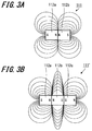
- FIG. 3A shows a state of magnetic flux distribution when two magnets 112a and 112b are connected.
- the magnets 112a and 112b repel each other when the same poles face each other.
- the magnetic flux distribution in the both ends of the movable magnet 111 is different from that in the center.
- the magnetic flux at the center of the movable magnet 111 has a higher density than the magnetic flux at both ends of the movable magnet 111. Therefore, in the conventional vibration type electromagnetic generator 110, the magnetic flux generated by the movable magnet 111 cannot be used effectively, and the voltage output from the solenoid coils 113a to 113c is low.
- FIG. 3B shows a state of magnetic flux distribution when three magnets 112a to 112c are connected.
- a movable magnet 111 ′ having three magnets 112a to 112c is taken as an example.
- the magnets 112a to 112c repel each other when the same poles face each other.
- the magnetic flux distribution is such that the magnet 112b arranged in the middle is perpendicular to the major axis direction of the magnets 112a to 112c compared to the magnets 112a and 112c arranged at both ends of the movable magnet 111 ′.
- High magnetic flux density For this reason, if the length of the solenoid coil is not changed so that the same magnetic flux as the magnetic flux generated by the magnet 112b passes, a phase shift occurs in the output voltage of each coil.
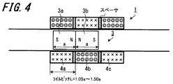
- the magnet length and the coil length are set in accordance with the following condition (A).
- a plurality of coil pitches are 1.05 times to 1.50 times, preferably 1.10 times to 1.4 times the major axis dimension of one magnet. Length.
- FIG. 4 shows a configuration example of the vibration type electromagnetic generator 1 according to the present invention including three solenoid coils and two magnets.
- the vibration type electromagnetic generator 1 having such a configuration is also referred to as “Example 1”.
- the vibration type electromagnetic generator 1 includes the movable magnet 3 including the two magnets 3a and 3b and the three solenoid coils 4a to 4c.
- a configuration is adopted in which a spacer is interposed between the solenoid coils 4a to 4c.
- the coil pitch is L and the magnet length is a, the relationship of 1.05a ⁇ L ⁇ 1.50a is satisfied.
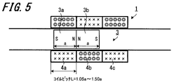
- FIG. 5 shows a configuration example of the vibration type electromagnetic generator 1 according to the present invention including three solenoid coils and two magnets.
- the vibration type electromagnetic generator 1 having such a configuration is also referred to as “Example 2”.
- the vibration type electromagnetic generator 1 has a configuration in which no spacer is provided between the solenoid coils 4a to 4c.
- the coil pitch is L and the magnet length is a, the relationship of 1.05a ⁇ L ⁇ 1.50a is satisfied.
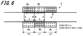
- FIG. 6 shows a configuration example of the vibration type electromagnetic generator 1 according to the present invention including three solenoid coils and two magnets.
- the vibration type electromagnetic generator 1 having such a configuration is also referred to as “Example 3”.
- the vibration type electromagnetic generator 1 has a configuration in which no spacer is provided between the solenoid coils 4a to 4c.
- the coil pitch of the solenoid coil 4b is L1
- the coil pitch of the solenoid coils 4a and 4c is L2
- the magnet length is a
- FIG. 7 shows an example of voltage waveforms output from the solenoid coils 113a to 113c provided in the conventional vibration type electromagnetic generator 110.
- voltage waveforms output from the solenoid coils 113a to 113c are displayed as voltage waveforms 115 to 117, respectively.
- a voltage waveform obtained by synthesizing the voltages output from the solenoid coils 113a to 113c is displayed as a voltage waveform 118. It can be seen from the voltage waveform 118 that the vibration type electromagnetic generator 110 outputs a voltage of ⁇ 3V.
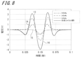
- FIG. 8 shows an example of voltage waveforms output from the solenoid coils 4a to 4c included in the vibration type electromagnetic generator 1 shown as the first embodiment.
- voltage waveforms output from the solenoid coils 4a to 4c are displayed as voltage waveforms 13 to 15, respectively.
- a voltage waveform obtained by synthesizing the voltages output from the solenoid coils 4a to 4c is displayed as a voltage waveform 16. It can be seen from the voltage waveform 16 that the vibration type electromagnetic generator 1 outputs a voltage of ⁇ 4V.
- the inventor obtains the optimum coil pitch of the vibration type electromagnetic power generator 110 according to the first embodiment.
- the voltage value output for each (long / magnet long axis dimension) was measured.
- the effective value of the voltage output from the vibration electromagnetic generator 110 shown in Comparative Example 1 is used as a reference, the effective value of the voltage output from the vibration electromagnetic generator 1 with the coil pitch ratio changed for each pattern.
- the ratio was calculated as the output effective value voltage increase rate.
- Table 1 The measurement results are shown in Table 1.
- the inventor measured the voltage value output for every five coil pitch ratios in order to obtain the optimum coil pitch of the vibration type electromagnetic generator 1 according to Examples 2 and 3.
- the vibration type electromagnetic generator 1 outputs when the coil pitch ratio is 1.05 to 1.50. It is shown that the effective value of the voltage increases.
- the movable magnet 3 includes magnets 3a and 3b having a strong magnetic force, an electromotive force generated in the power generation coil 9 of the vibration type electromagnetic generator 1 is increased as compared with a case where a magnet having a weak magnetic force is used.
- the opposed magnets are strongly repelled. For this reason, a special device is required for the method of manufacturing the movable magnet 3.
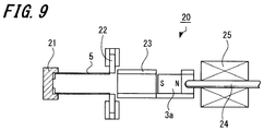
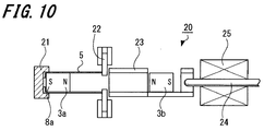
- FIG. 9 shows an example of a state in which the magnet 3 a is set in the movable magnet assembling apparatus 20.
- the movable magnet assembling apparatus 20 includes a positioning stopper portion 21 that holds the second pipe 5 according to the length, a pop-out pressing portion 22 that presses the magnet so that the magnet does not jump out of the second pipe 5, and a magnet A magnet guide 23 having an insertion port for inserting the magnet straight into the second pipe 5, a push rod 24 for pushing the magnet into the second pipe 5, and a push rod control device 25 for controlling the push of the push rod 24. And comprising.
- One end portion of the second pipe 5 is fixed to the positioning stopper portion 21 in advance, and is crimped and fixed in advance. Then, the magnet 3 a is set on the magnet guide 23.
- FIG. 10 shows an example of a state in which the magnet 3 b is set in the movable magnet assembling apparatus 20 after the set magnet 3 a is pushed into the second pipe 5 by the push rod 24.
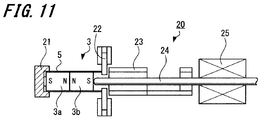
- FIG. 11 shows an example of a state in which the magnet 3 b is pushed into the second pipe 5.
- the magnet 3a is pushed into the back of the second pipe 5, and the N pole of the magnet 3a faces the magnet 3b.
- the magnet 3b is inserted into the second pipe 5 with the N pole of the magnet 3b facing the magnet 3a.
- magnet 3a, 3b produces repulsive force mutually. The repulsive force may cause the magnet 3b to jump out of the second pipe 5.
- the magnet 3b does not jump out of the second pipe 5.
- the part which the 2nd pipe 5 and the magnet 3b have overlapped can be fixed and sealed by heat welding or adhesion
- the movable magnet 3 is integrally joined by caulking both ends of the second pipe 5, it is not easily disassembled even if an impact is applied. Furthermore, an adhesive may be applied to the inner wall surface of the second pipe 5 to bond and fix the second pipe 5 and the magnets 3a and 3b. Needless to say, an adhesive having a sufficiently large adhesive strength to the resin to be used is selected as the adhesive used at this time.
- the process of setting the magnet in the movable magnet assembling apparatus 20 and pushing it into the second pipe 5 may be repeated as shown in FIGS. Further, as shown in FIG. 1, the second pipe 5 has a configuration in which both ends are closed by caulking, but only one of the one ends may be closed by caulking. At this time, the second pipe 5 may have a bottomed cylindrical configuration.
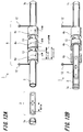
- FIG. 12A and 12B show an external configuration example of the vibration type electromagnetic generator 1.
- FIG. 12A is a perspective view of a state in which each component constituting the vibration type electromagnetic generator 1 is disassembled.
- FIG. 12B is a partial perspective view of a part of the first pipe 2 in the vibration type electromagnetic generator 1 in which the components are combined.
- the solenoid coils 4a to 4c are wound around the outer peripheral surface of the cylindrical first pipe 2 that houses the movable magnet 3 with a predetermined coil interval.
- the solenoid coils 4a to 4c are connected in series.
- Each solenoid coil is wound in a direction opposite to each other, and has a normal winding, a reverse winding, and a normal winding. From the solenoid coil 4a and the solenoid coil 4c, coil ends 12 are drawn out and connected to an external load (not shown).
- end members 7 a and 7 b are attached to both ends of the first pipe 2.
- the movable magnet 3 moves smoothly in the first pipe 2 and therefore moves in the direction of the winding axis inside the solenoid coils 4a to 4c. Therefore, the solenoid coils 4a to 4c generate voltage and function as a generator.
- the coil length of one or more solenoid coils is set to a length equal to or longer than the magnet length of the magnet. For this reason, the range in which the magnetic field generated by the magnet passes through the solenoid coil can be expanded, the phase of the voltage output by the solenoid coil can be matched, and the output voltage of the vibration type electromagnetic generator 1 can be increased. is there.
- the movable magnet 3 includes a plurality of magnets (magnets 3a and 3b) arranged so that the opposing magnetic poles are the same. Since the plurality of magnets have a simple configuration of being inserted into the second pipe 5, there is an effect that the assembly of the movable magnet 3 is extremely easy.
- the process of forming the movable magnet 3 is only a simple operation of inserting the magnets 3a and 3b along the inner wall surface of the second pipe 5. Since the plurality of magnets inserted into the second pipe 5 and the magnet end members are forcibly aligned, the outer peripheral surface of the movable magnet 3 is not distorted. For this reason, when the movable magnet 3 vibrates, unnecessary frictional resistance generated on the inner wall surfaces of the movable magnet 3 and the first pipe 2 is suppressed. As a result, there is an effect that the vibration type electromagnetic generator 1 having excellent power generation efficiency can be realized.
- the plurality of magnets face each other with the same polarity, the magnetic flux distribution of the magnetic flux interlinking with the power generation coil 9 increases rapidly. As a result, there is an effect that the power generation efficiency of the vibration type electromagnetic generator 1 is increased.
- the welding process by a heating or a solvent can be made into a sealing process. For this reason, there exists an effect that manufacture of the movable magnet 3 can be made easy.
- the outer diameter of the magnet is slightly smaller than the inner diameter of the second pipe 5. In this way, when the movable magnet 3 is assembled by the movable magnet assembling apparatus 20, air is not compressed inside the second pipe 5 and does not become a resistance force against the pressing force of the push rod 24. Alternatively, the compressed air may be released by forming a groove or the like in the magnet.
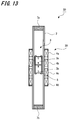
- FIG. 13 shows a configuration example of a vibration type electromagnetic generator 30 including four solenoid coils and two magnets.
- the vibration type electromagnetic generator 30 includes a movable magnet 3 composed of two magnets 3a and 3b connected to each other, and four solenoid coils 4a to 4d.
- the four solenoid coils 4a to 4d are also referred to as power generation coils 39.
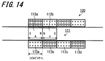
- FIG. 14 shows a configuration example of a conventional vibration type electromagnetic power generator 120 including four solenoid coils and two magnets.
- the vibration type electromagnetic generator 120 having such a configuration is also referred to as “Comparative Example 2”.
- the conventional vibration type electromagnetic generator 120 includes a movable magnet 111 composed of two magnets 112a and 112b connected to each other, and four solenoid coils 113a to 113d.
- FIG. 15 shows a configuration example of a vibration type electromagnetic generator 30 according to the present invention including four solenoid coils and two magnets.
- the vibration type electromagnetic generator 30 having such a configuration is also referred to as “Example 4”.
- the vibration electromagnetic generator 30 includes the movable magnet 3 including the two magnets 3a and 3b and the four solenoid coils 4a to 4d.
- the coil pitch of the solenoid coils 4a and 4d arranged at both ends is L2
- the coil pitch of the solenoid coils 4b and 4c arranged in the middle is L1
- the inventor obtains the coil pitch ratio of five patterns. The voltage value output to was measured. Then, when the effective value of the voltage output from the vibration electromagnetic generator 120 shown in Comparative Example 2 is used as a reference, the effective value of the voltage output from the vibration electromagnetic generator 30 with the coil pitch ratio changed for each pattern. The ratio was calculated as the output effective value voltage increase rate. The measurement results are shown in Table 4.
- the coil pitch of the solenoid coils 4a and 4d arranged at both ends is made longer than the magnet length of the magnets 3a and 3b. There is an effect that the voltage output from the vibration type electromagnetic generator 30 increases.
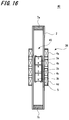
- FIG. 16 shows a configuration example of a vibration type electromagnetic generator 40 including four solenoid coils and three magnets.
- the vibration type electromagnetic generator 40 includes a movable magnet 43 composed of three magnets 3a to 3c and a power generation coil 39 composed of four solenoid coils 4a to 4d connected to each other.
- the vibration type electromagnetic generator 40 makes the solenoid coil length arranged at both ends of the power generation coil 39 longer than the magnet length with respect to the magnet length.
- the vibration type electromagnetic generator 40 is configured such that the major axis dimension of the magnets arranged at both ends of the movable magnet 3 is 0.70 times to 0.95 times with respect to the pitch of the plurality of coils.
- the length is preferably between 0.80 times and 0.92 times, and the major axis dimensions of the magnets arranged at both ends of the movable magnet 3 are made equal to the coil pitch.
- the configuration and output voltage of the conventional vibration type electromagnetic generator 130 and the vibration type electromagnetic generator 40 according to the present embodiment will be compared.
- FIG. 17 shows a configuration example of a conventional vibration type electromagnetic generator 130 including four solenoid coils and three magnets.
- the vibration type electromagnetic generator 130 having such a configuration is also referred to as “Comparative Example 3”.
- the conventional vibration type electromagnetic generator 130 includes a movable magnet 131 composed of three magnets 132a to 132c connected to each other, and four solenoid coils 133a to 133.
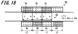
- FIG. 18 shows a configuration example of a vibration type electromagnetic generator 40 according to the present invention including four solenoid coils and three magnets.
- the vibration type electromagnetic generator 40 having such a configuration is also referred to as “Example 5”.
- the magnet length of the magnets 3a to 3c is a
- the coil pitch of the solenoid coils 4b and 4c is L1
- the coil pitch of the solenoid coils 4a and 4d is L2.
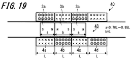
- FIG. 19 shows a configuration example of a vibration type electromagnetic generator 40 according to the present invention including four solenoid coils and three magnets.
- the vibration type electromagnetic generator 40 having such a configuration is also referred to as “Example 6”.
- the magnet lengths of the magnets 3a and 3c are a, and the magnet length of the magnet 3b is b.
- the inventor obtains five patterns of magnet pitch ratios ( The voltage value output for each major axis dimension / coil pitch of the magnets arranged at both ends was measured. Then, when the effective value of the voltage output from the vibration electromagnetic generator 130 shown in Comparative Example 3 is used as a reference, the effective value of the voltage output from the vibration electromagnetic generator 40 with the magnet pitch ratio changed for each pattern. The ratio was calculated as the output effective value voltage increase rate. The measurement results are shown in Table 5.
- the vibration type electromagnetic generator 40 outputs a high voltage.
- the inventor measured the voltage value output for every nine patterns of the magnet pitch ratio.
- the coil pitch of the solenoid coils 4a and 4d arranged at both ends is made longer than the magnet length of the magnets 3a and 3b. There is an effect that the voltage output from the vibration type electromagnetic generator 40 increases.
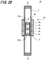
- the configuration of the vibration type electromagnetic generator 50 is substantially the same as the configuration of the vibration type electromagnetic generator 1 described above, but the configuration of the movable magnet 53 is different from that of the movable magnet 3.
- the movable magnet 53 includes magnet end members 51a and 51b made of a nonmagnetic material in order to protect the magnets 3a and 3b disposed on the second pipe 5.
- the magnet end members 51a and 51b are formed of a thermoplastic resin or a thermosetting resin in order to securely seal both ends of the second pipe 5. Since the magnet end members 51a and 51b are joined to the second pipe 5 by thermal welding as described later, it is desirable that these materials are the same. Note that the second pipe 5 and the magnet end members 51a and 51b may be bonded and fixed using an adhesive or the like. However, if an adhesive having good adhesiveness is used, it is not necessary to use the same material for the second pipe 5 and the magnet end members 51a and 51b.
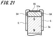
- FIG. 21 is an enlarged view showing the vicinity of the magnet end member 51 a attached to the movable magnet 3.
- a magnet end member 51 a formed of a thermoplastic resin is disposed at the end of the second pipe 5.
- the magnet end member 51 a and the end portion of the second pipe 5 are heat-welded to form a heat-welded portion 54.
- the magnet end member 51a is provided at the end of the second pipe 5, heat is hardly transmitted to the magnets 3a and 3b. That is, it can be said that the configuration in which the magnet end member 51a is disposed at the end of the second pipe 5 is a desirable form when the sealing process is performed by the heating means.
- an adhesive 55 is used at both ends of the movable magnet 3.
- an adhesive exhibiting sufficient adhesiveness to the resin to be used is used.
- the adhesive 55 used at both ends of the movable magnet 3 penetrates into the joint surface between the second pipe 5 and the magnet end member 51a. And the 2nd pipe 5 and the magnet end member 51a are couple
- the 2nd pipe 5 and the magnet end member 51a are fully used using an organic adhesive etc. It is necessary to bond and fix.
- the size and shape of the gap may be devised so that the adhesive sufficiently flows into the gap between the second pipe 5 and the magnet end member 51a.
- the vicinity of the magnet end member 51b of the movable magnet 3 has the same configuration as that of the magnet end member 51a, and thus detailed description of the configuration example near the magnet end member 51b is omitted.
- the magnets 3a and 3b are sealed inside the second pipe 5 and fixed by an adhesive or the like, and the strength is also improved. . For this reason, even if an impact is applied to the movable magnet 3 due to vibration during power generation, the possibility of damage to the movable magnet is reduced.
- magnet end members 51 a and 51 b are arranged at both ends of the movable magnet 3.
- the non-magnetic metal represented by aluminum, copper, brass etc. is used for the material of the 2nd pipe 5, for example.
- both ends of the second pipe 5 are sealed by caulking. If such a manufacturing method is used, only the magnet end members 51a and 51b are deformed, and unnecessary stress is not applied to or deformed at the ends of the plurality of magnets.
- heat is not applied to a plurality of magnets, deterioration of the magnets can be suppressed. As a result, there is an effect that variations in magnetic flux density generated by a plurality of magnets can be reduced.
- the magnet end members 51a and 51b are not necessarily indispensable if the caulking method is optimized so that excessive stress is not applied to the magnet.
- the movable magnet 3 can be manufactured by substantially the same manufacturing method as that of the first embodiment described above, if an adhesive fixing means is used.
- the second pipe 5 and the magnet end members 51a and 51b are not bonded using an adhesive, but the inner wall surface of the second pipe 5 and the magnet end members 51a and 51b are cut in advance.
- the magnet end members 51 a and 51 b may be fixed to the second pipe 5 with screws.
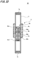
- the movable magnet 63 is configured by sandwiching and fixing ring-shaped magnets 65a to 65c having the same poles facing each other and having a through-hole at the center by magnet fixing portions 61a and 61b made of a non-magnetic material.
- the magnet fixing part 61a is, for example, a bolt.
- the magnet fixing part 61b is, for example, a nut.
- the magnet fixing portions 61a and 61b are formed with flange portions whose side surfaces are processed into a circular or polygonal shape.
- the magnet fixing part 61a has a core part and a collar part inserted into the through holes of the magnets 65a to 65c, and the core part and the collar part are integrally formed.
- the core portion is located on the central axis of the first pipe 2 and is formed to have a thickness approximately equal to or slightly thinner than the diameter of the through hole of the magnets 65a to 65c.
- a male screw (male part) for fixing the magnet fixing part 61b is processed and formed on the upper side (tip part) of the core part.
- a female screw (female part) which is a connection hole to which the tip of the core part is connected, is processed and formed in the central part of the magnet fixing part 61b.
- the ring-shaped magnets 65a to 65c facing each other and repelling each other are sandwiched and fixed by the magnet fixing part 61b so as not to be detached from the core part.
- the core portion of the magnet fixing portion 61a is formed into a tip-shaped shape, and the tip portion thereof is a hook-shaped portion (male shape). And a hole (female part) for fitting the hook-shaped part in the magnet fixing part 61b.
- a magnet can be fixed by fitting each other. For this reason, it has the advantage that an assembly of a movable magnet becomes easy compared with the structure of the above-mentioned male screw and female screw.
- the collar portion of the magnet fixing portion 61a has a width larger than the width of the magnets 65a to 65c with respect to the central axis of the first pipe 2.
- the collar portion of the magnet fixing portion 61b has a width larger than the width of the magnets 65a to 65c with respect to the central axis of the first pipe 2. At this time, it is more desirable that the shape and dimensions of the collar portion of the magnet fixing portion 61a and the collar portion of the magnet fixing portion 61b are the same.
- suitable materials for the magnet fixing portion 61b (nut) and the magnet fixing portion 61a (bolt) include polyacetal materials for resins and aluminum for metals.
- a polytetrafluoroethylene-based material may be used as the material for the magnet fixing portion 61b (nut) and the magnet fixing portion 61a (bolt). Since this material has a very low coefficient of friction, it is excellent in slidability of the movable magnet 63. However, when the magnet fixing portion 61a is screwed to the magnet fixing portion 61b, the friction may not be maintained.
- the tip of the magnet fixing portion 61a (bolt) is crushed or the tip of the core portion of the magnet fixing portion 61a is used as a bowl-shaped portion. It is desirable to prevent loosening of the magnet fixing portions 61a and 61b by forming holes in the fixing portion 61b and fitting them together.
- the vibration type electromagnetic generator 50 includes the movable magnet 63 in which the three magnets 65a to 65c facing the same pole are fixed by the magnet fixing portions 61a and 61b. Moreover, since both ends of the movable magnet 63 are protected by the flange portions of the magnet fixing portions 61a and 61b, even if they contact the end members 7a and 7b, the impact is not directly transmitted. For this reason, even when the vibration type electromagnetic generator 50 is shaken for a long time, the magnets 65a to 65c are not damaged.
- the contact between the movable magnet 63 and the inner peripheral surface of the first pipe 2 is only the collar and the side peripheral surface of the magnet fixing portion 61b. For this reason, there is an advantage that the friction between the movable magnet 63 and the first pipe 2 is reduced, and the slidability of the movable magnet 63 is improved.
- the movable magnet can be moved inside the first pipe 2, but in order to support the movable magnet, the first At least one coil spring (tensile spring) may be installed inside the pipe 2.
- tensile spring tensile spring
- a coil spring may be installed in the gravitational direction (upper side) of the movable magnet.
- two compression springs may be used as the elastic body. Even if it is a compression spring, both ends of the movable magnet can be supported so as to vibrate in the direction of the winding axis of the power generation coil. Furthermore, a single compression spring may be used. In this case, the compression spring may be installed in the gravity direction (lower side) of the movable magnet. Even with such a configuration, it is possible to suitably generate power.
- the weak vibration energy can be efficiently converted into the linear reciprocating motion of the movable magnet.
- the vibration type electromagnetic generator is parallel to the direction of gravity and the installation direction of the vibration type electromagnetic generator is constant, for example, for the safe navigation of a marine vessel, It can be said that it is suitable as a generator for a light emitting buoy that generates electric power by movement and emits light. It can also be employed in a bicycle carrier or saddle, or in a car suspension.
- the magnets adjacent to each other are arranged so as to face each other, but different poles may be arranged so as to face each other. Further, the number of magnets may be larger than the number of solenoid coils.
- SYMBOLS 1 Vibration type electromagnetic generator, 2 ... 1st pipe, 3 ... Movable magnet, 3a, 3b ... Magnet, 4a-4c ... Solenoid coil, 5 ... 2nd pipe, 7a, 7b ... End member, 9 ... Power generation Coil, 12 ... coil end, 20 ... movable magnet assembly device, 30 ... vibration type electromagnetic generator, 39 ... power generation coil, 40 ... vibration type electromagnetic generator, 43 ... movable magnet, 50 ... vibration type electromagnetic generator, 51a , 51b ... Magnet end member, 53 ... Movable magnet, 60 ... Vibration type electromagnetic generator, 61a, 61b ... Magnet fixing part, 63 ... Movable magnet, 65a, 65b ... Magnet
Landscapes
- Engineering & Computer Science (AREA)
- Power Engineering (AREA)
- Reciprocating, Oscillating Or Vibrating Motors (AREA)
- Apparatuses For Generation Of Mechanical Vibrations (AREA)
Priority Applications (3)
| Application Number | Priority Date | Filing Date | Title |
|---|---|---|---|
| KR1020127010595A KR101341928B1 (ko) | 2010-01-14 | 2010-08-27 | 진동형 전자발전기 |
| CN201080061499.7A CN102714453B (zh) | 2010-01-14 | 2010-08-27 | 振动型电磁发电机 |
| US13/521,789 US9257891B2 (en) | 2010-01-14 | 2010-08-27 | Vibration type electromagnetic generator |
Applications Claiming Priority (2)
| Application Number | Priority Date | Filing Date | Title |
|---|---|---|---|
| JP2010006299A JP5760316B2 (ja) | 2010-01-14 | 2010-01-14 | 振動型電磁発電機 |
| JP2010-006299 | 2010-01-14 |
Related Child Applications (1)
| Application Number | Title | Priority Date | Filing Date |
|---|---|---|---|
| US13/521,789 Substitution US9257891B2 (en) | 2010-01-14 | 2010-08-27 | Vibration type electromagnetic generator |
Publications (1)
| Publication Number | Publication Date |
|---|---|
| WO2011086726A1 true WO2011086726A1 (ja) | 2011-07-21 |
Family
ID=44304024
Family Applications (1)
| Application Number | Title | Priority Date | Filing Date |
|---|---|---|---|
| PCT/JP2010/064624 Ceased WO2011086726A1 (ja) | 2010-01-14 | 2010-08-27 | 振動型電磁発電機 |
Country Status (5)
| Country | Link |
|---|---|
| US (1) | US9257891B2 (enExample) |
| JP (1) | JP5760316B2 (enExample) |
| KR (1) | KR101341928B1 (enExample) |
| CN (1) | CN102714453B (enExample) |
| WO (1) | WO2011086726A1 (enExample) |
Cited By (1)
| Publication number | Priority date | Publication date | Assignee | Title |
|---|---|---|---|---|
| JP2015084647A (ja) * | 2015-02-03 | 2015-04-30 | スミダコーポレーション株式会社 | 振動型電磁発電機 |
Families Citing this family (25)
| Publication number | Priority date | Publication date | Assignee | Title |
|---|---|---|---|---|
| JP5553064B2 (ja) * | 2011-08-31 | 2014-07-16 | ブラザー工業株式会社 | 振動発電機 |
| JP5811719B2 (ja) | 2011-09-14 | 2015-11-11 | スミダコーポレーション株式会社 | 振動発電機 |
| JP6074939B2 (ja) * | 2012-07-27 | 2017-02-08 | ソニー株式会社 | 発電機 |
| CN102866205B (zh) * | 2012-09-12 | 2015-07-15 | 田志恒 | 电磁超声换能器及包括该换能器的在线探伤系统 |
| KR101354158B1 (ko) * | 2012-09-28 | 2014-01-23 | 울산대학교 산학협력단 | 진동형 전자기식 에너지 하베스터 |
| US8629572B1 (en) * | 2012-10-29 | 2014-01-14 | Reed E. Phillips | Linear faraday induction generator for the generation of electrical power from ocean wave kinetic energy and arrangements thereof |
| US9624900B2 (en) * | 2012-10-29 | 2017-04-18 | Energystics, Ltd. | Linear faraday induction generator for the generation of electrical power from ocean wave kinetic energy and arrangements thereof |
| CN103312112A (zh) * | 2013-06-03 | 2013-09-18 | 苏州启智机电技术有限公司 | 磁力电池 |
| CN103280291A (zh) * | 2013-06-03 | 2013-09-04 | 苏州启智机电技术有限公司 | 翻转式磁能电池 |
| KR101501389B1 (ko) * | 2013-11-14 | 2015-03-12 | 울산대학교 산학협력단 | 공진주파수 조절이 가능한 에너지 하베스터 |
| CN106438179B (zh) * | 2016-11-29 | 2021-09-07 | 崔同锁 | 浪涌发电机 |
| CN106411094B (zh) * | 2016-11-30 | 2019-03-22 | 杨明远 | 一种永磁振动发电便携电源 |
| KR102692165B1 (ko) * | 2017-02-07 | 2024-08-06 | 엘지전자 주식회사 | 횡자속형 왕복동 모터 및 이를 구비한 왕복동식 압축기 |
| US10352290B2 (en) * | 2017-02-14 | 2019-07-16 | The Texas A&M University System | Method and apparatus for wave energy conversion |
| KR101881691B1 (ko) * | 2017-02-27 | 2018-07-24 | 김대현 | 2축 짐볼 구조를 가진 에너지 하베스팅 모듈 및 이를 포함하는 에너지 하베스팅 장치 |
| KR101968481B1 (ko) * | 2017-11-21 | 2019-04-15 | (주)이미지스테크놀로지 | 충격식 진동 액츄에이터 |
| CN108900060A (zh) * | 2018-09-03 | 2018-11-27 | 北京航空航天大学 | 磁流体润滑型间隙谐振高频振动电磁俘能器 |
| JP7660868B2 (ja) * | 2018-10-31 | 2025-04-14 | ヤマウチ株式会社 | 振動ダイナモ装置およびスイッチ機構付きダイナモ装置 |
| KR102317418B1 (ko) * | 2020-04-24 | 2021-10-26 | 주식회사 휴젝트 | 전자기 유도를 이용하는 에너지 하베스팅 장치 |
| CN113545968A (zh) | 2020-04-24 | 2021-10-26 | 人类工程株式会社 | 利用电磁感应的能量收集装置及智能手杖 |
| US11711005B2 (en) * | 2020-05-12 | 2023-07-25 | Richard L Lewis | Vibration-based electric generation device |
| CN112855419B (zh) * | 2021-04-08 | 2021-09-24 | 浙江大学 | 一种波浪洋流混合发电装置及方法 |
| WO2023102781A1 (zh) * | 2021-12-08 | 2023-06-15 | 陈功林 | 获取电能的方法和装置 |
| DE102023130832A1 (de) * | 2023-11-07 | 2025-05-22 | TET ENERGY GmbH | Stromerzeugungseinrichtung |
| CN119422653A (zh) * | 2024-12-09 | 2025-02-14 | 潍柴雷沃智慧农业科技股份有限公司 | 一种割刀驱动装置及收获机 |
Citations (3)
| Publication number | Priority date | Publication date | Assignee | Title |
|---|---|---|---|---|
| WO2008139646A1 (ja) * | 2007-05-09 | 2008-11-20 | Sumida Corporation | 振動型電磁発電機及び振動型電磁発電機の製造方法 |
| JP2009118581A (ja) * | 2007-11-02 | 2009-05-28 | Sumida Corporation | 振動型電磁発電機 |
| JP2009213194A (ja) * | 2008-02-29 | 2009-09-17 | Sumida Corporation | 振動型電磁発電機 |
Family Cites Families (11)
| Publication number | Priority date | Publication date | Assignee | Title |
|---|---|---|---|---|
| US4937481A (en) * | 1989-01-13 | 1990-06-26 | Mechanical Technology Incorporated | Permanent magnet linear electromagnetic machine |
| JPH03273858A (ja) * | 1990-03-20 | 1991-12-05 | Aisin Seiki Co Ltd | リニア発電機 |
| JP3215362B2 (ja) * | 1997-10-20 | 2001-10-02 | キヤノン株式会社 | リニアモータ、ステージ装置および露光装置 |
| JP2002281727A (ja) * | 2001-03-19 | 2002-09-27 | Sugino Mach Ltd | 振動発電機および発光装置 |
| JP4684106B2 (ja) * | 2003-08-28 | 2011-05-18 | テレダイン・ライセンシング・エルエルシー | 結合された磁石による発電 |
| JP4704093B2 (ja) * | 2005-04-14 | 2011-06-15 | スミダコーポレーション株式会社 | 振動発電機 |
| WO2008091274A2 (en) * | 2006-06-26 | 2008-07-31 | Battelle Energy Alliance, Llc | Coil structure |
| US20090295520A1 (en) * | 2006-06-26 | 2009-12-03 | Battelle Energy Alliance, Llc | Magnetic structure |
| US7701093B2 (en) * | 2007-03-08 | 2010-04-20 | Sanyo Denki Co., Ltd. | Linear motor |
| EA015065B1 (ru) | 2007-04-04 | 2011-04-29 | Сумитомо Метал Индастриз, Лтд. | Несущий элемент для кузова автомобиля, передний боковой элемент и боковая конструкция для кузова автомобиля |
| WO2011040265A1 (ja) * | 2009-09-29 | 2011-04-07 | ブラザー工業株式会社 | 振動発電機 |
-
2010
- 2010-01-14 JP JP2010006299A patent/JP5760316B2/ja not_active Expired - Fee Related
- 2010-08-27 WO PCT/JP2010/064624 patent/WO2011086726A1/ja not_active Ceased
- 2010-08-27 KR KR1020127010595A patent/KR101341928B1/ko not_active Expired - Fee Related
- 2010-08-27 CN CN201080061499.7A patent/CN102714453B/zh not_active Expired - Fee Related
- 2010-08-27 US US13/521,789 patent/US9257891B2/en not_active Expired - Fee Related
Patent Citations (3)
| Publication number | Priority date | Publication date | Assignee | Title |
|---|---|---|---|---|
| WO2008139646A1 (ja) * | 2007-05-09 | 2008-11-20 | Sumida Corporation | 振動型電磁発電機及び振動型電磁発電機の製造方法 |
| JP2009118581A (ja) * | 2007-11-02 | 2009-05-28 | Sumida Corporation | 振動型電磁発電機 |
| JP2009213194A (ja) * | 2008-02-29 | 2009-09-17 | Sumida Corporation | 振動型電磁発電機 |
Cited By (1)
| Publication number | Priority date | Publication date | Assignee | Title |
|---|---|---|---|---|
| JP2015084647A (ja) * | 2015-02-03 | 2015-04-30 | スミダコーポレーション株式会社 | 振動型電磁発電機 |
Also Published As
| Publication number | Publication date |
|---|---|
| KR20120061994A (ko) | 2012-06-13 |
| US9257891B2 (en) | 2016-02-09 |
| JP5760316B2 (ja) | 2015-08-05 |
| US20130221768A1 (en) | 2013-08-29 |
| KR101341928B1 (ko) | 2013-12-16 |
| CN102714453A (zh) | 2012-10-03 |
| CN102714453B (zh) | 2015-08-19 |
| JP2011147276A (ja) | 2011-07-28 |
Similar Documents
| Publication | Publication Date | Title |
|---|---|---|
| JP5760316B2 (ja) | 振動型電磁発電機 | |
| JP4649668B2 (ja) | 振動型電磁発電機 | |
| JP5537984B2 (ja) | 往復振動発生器 | |
| JP5659426B2 (ja) | 振動発生装置 | |
| KR101166050B1 (ko) | 진동형 전자발전기 및 진동형 전자발전기의 제조방법 | |
| JP5417719B2 (ja) | 振動型電磁発電機 | |
| US20150155472A1 (en) | Power generating element | |
| JP5637028B2 (ja) | 振動発電機 | |
| JP4680317B2 (ja) | 振動型電磁発電機 | |
| US12337346B2 (en) | Vibration actuator and electronic device | |
| JP2009100523A (ja) | 永久磁石素子並びに振動発電機および加速度センサ | |
| KR20140013894A (ko) | 스피커 | |
| WO2021035826A1 (zh) | 一种线圈内嵌套法兰磁轭的线性马达 | |
| US12225827B2 (en) | Power generation element and power generation apparatus | |
| JP6004024B2 (ja) | 振動型電磁発電機 | |
| KR101504867B1 (ko) | 능동형 에너지 수확기 | |
| JP2015208179A (ja) | 発電装置 | |
| US10877563B2 (en) | Haptic actuator including overmolded field member and related methods | |
| JP6093573B2 (ja) | 発電素子のカバー | |
| US12069954B2 (en) | Power generating element and apparatus including power generating element | |
| WO2014168008A1 (ja) | 発電装置 | |
| WO2014168007A1 (ja) | 発電装置 | |
| WO2015022886A1 (ja) | 発電装置 | |
| JP2015122855A (ja) | 発電素子 | |
| WO2017038750A1 (ja) | 発電素子、ダイナミックダンパーおよびトーショナルダンパー |
Legal Events
| Date | Code | Title | Description |
|---|---|---|---|
| WWE | Wipo information: entry into national phase |
Ref document number: 201080061499.7 Country of ref document: CN |
|
| 121 | Ep: the epo has been informed by wipo that ep was designated in this application |
Ref document number: 10843083 Country of ref document: EP Kind code of ref document: A1 |
|
| ENP | Entry into the national phase |
Ref document number: 20127010595 Country of ref document: KR Kind code of ref document: A |
|
| NENP | Non-entry into the national phase |
Ref country code: DE |
|
| WWE | Wipo information: entry into national phase |
Ref document number: 13521789 Country of ref document: US |
|
| 122 | Ep: pct application non-entry in european phase |
Ref document number: 10843083 Country of ref document: EP Kind code of ref document: A1 |