WO2011077907A1 - 作業機用エンジン - Google Patents
作業機用エンジン Download PDFInfo
- Publication number
- WO2011077907A1 WO2011077907A1 PCT/JP2010/071406 JP2010071406W WO2011077907A1 WO 2011077907 A1 WO2011077907 A1 WO 2011077907A1 JP 2010071406 W JP2010071406 W JP 2010071406W WO 2011077907 A1 WO2011077907 A1 WO 2011077907A1
- Authority
- WO
- WIPO (PCT)
- Prior art keywords
- fuel
- air
- chamber
- passage
- lubricating oil
- Prior art date
- Legal status (The legal status is an assumption and is not a legal conclusion. Google has not performed a legal analysis and makes no representation as to the accuracy of the status listed.)
- Ceased
Links
Images


Classifications
-
- F—MECHANICAL ENGINEERING; LIGHTING; HEATING; WEAPONS; BLASTING
- F02—COMBUSTION ENGINES; HOT-GAS OR COMBUSTION-PRODUCT ENGINE PLANTS
- F02D—CONTROLLING COMBUSTION ENGINES
- F02D41/00—Electrical control of supply of combustible mixture or its constituents
- F02D41/0025—Controlling engines characterised by use of non-liquid fuels, pluralities of fuels, or non-fuel substances added to the combustible mixtures
-
- F—MECHANICAL ENGINEERING; LIGHTING; HEATING; WEAPONS; BLASTING
- F01—MACHINES OR ENGINES IN GENERAL; ENGINE PLANTS IN GENERAL; STEAM ENGINES
- F01M—LUBRICATING OF MACHINES OR ENGINES IN GENERAL; LUBRICATING INTERNAL COMBUSTION ENGINES; CRANKCASE VENTILATING
- F01M1/00—Pressure lubrication
- F01M1/04—Pressure lubrication using pressure in working cylinder or crankcase to operate lubricant feeding devices
-
- F—MECHANICAL ENGINEERING; LIGHTING; HEATING; WEAPONS; BLASTING
- F01—MACHINES OR ENGINES IN GENERAL; ENGINE PLANTS IN GENERAL; STEAM ENGINES
- F01M—LUBRICATING OF MACHINES OR ENGINES IN GENERAL; LUBRICATING INTERNAL COMBUSTION ENGINES; CRANKCASE VENTILATING
- F01M11/00—Component parts, details or accessories, not provided for in, or of interest apart from, groups F01M1/00 - F01M9/00
- F01M11/06—Means for keeping lubricant level constant or for accommodating movement or position of machines or engines
- F01M11/062—Accommodating movement or position of machines or engines, e.g. dry sumps
- F01M11/065—Position
-
- F—MECHANICAL ENGINEERING; LIGHTING; HEATING; WEAPONS; BLASTING
- F02—COMBUSTION ENGINES; HOT-GAS OR COMBUSTION-PRODUCT ENGINE PLANTS
- F02D—CONTROLLING COMBUSTION ENGINES
- F02D35/00—Controlling engines, dependent on conditions exterior or interior to engines, not otherwise provided for
- F02D35/0015—Controlling engines, dependent on conditions exterior or interior to engines, not otherwise provided for using exhaust gas sensors
- F02D35/0046—Controlling fuel supply
- F02D35/0053—Controlling fuel supply by means of a carburettor
-
- F—MECHANICAL ENGINEERING; LIGHTING; HEATING; WEAPONS; BLASTING
- F02—COMBUSTION ENGINES; HOT-GAS OR COMBUSTION-PRODUCT ENGINE PLANTS
- F02M—SUPPLYING COMBUSTION ENGINES IN GENERAL WITH COMBUSTIBLE MIXTURES OR CONSTITUENTS THEREOF
- F02M17/00—Carburettors having pertinent characteristics not provided for in, or of interest apart from, the apparatus of preceding main groups F02M1/00 - F02M15/00
- F02M17/02—Floatless carburettors
- F02M17/04—Floatless carburettors having fuel inlet valve controlled by diaphragm
-
- F—MECHANICAL ENGINEERING; LIGHTING; HEATING; WEAPONS; BLASTING
- F02—COMBUSTION ENGINES; HOT-GAS OR COMBUSTION-PRODUCT ENGINE PLANTS
- F02M—SUPPLYING COMBUSTION ENGINES IN GENERAL WITH COMBUSTIBLE MIXTURES OR CONSTITUENTS THEREOF
- F02M19/00—Details, component parts, or accessories of carburettors, not provided for in, or of interest apart from, the apparatus of groups F02M1/00 - F02M17/00
- F02M19/02—Metering-orifices, e.g. variable in diameter
- F02M19/0203—Metering-orifices, e.g. variable in diameter the cross-sectional area being changed pneumatically, e.g. vacuum dependent
-
- F—MECHANICAL ENGINEERING; LIGHTING; HEATING; WEAPONS; BLASTING
- F02—COMBUSTION ENGINES; HOT-GAS OR COMBUSTION-PRODUCT ENGINE PLANTS
- F02M—SUPPLYING COMBUSTION ENGINES IN GENERAL WITH COMBUSTIBLE MIXTURES OR CONSTITUENTS THEREOF
- F02M19/00—Details, component parts, or accessories of carburettors, not provided for in, or of interest apart from, the apparatus of groups F02M1/00 - F02M17/00
- F02M19/02—Metering-orifices, e.g. variable in diameter
- F02M19/0225—Arrangement of nozzle in the suction passage
-
- F—MECHANICAL ENGINEERING; LIGHTING; HEATING; WEAPONS; BLASTING
- F02—COMBUSTION ENGINES; HOT-GAS OR COMBUSTION-PRODUCT ENGINE PLANTS
- F02D—CONTROLLING COMBUSTION ENGINES
- F02D2400/00—Control systems adapted for specific engine types; Special features of engine control systems not otherwise provided for; Power supply, connectors or cabling for engine control systems
- F02D2400/06—Small engines with electronic control, e.g. for hand held tools
Definitions
- the present invention relates to an engine used in a working machine such as a brush cutter.
- an engine for a working machine having a configuration as shown in Patent Document 1 is known.
- Such an engine for a working machine uses gasoline as fuel, and an explosion action is brought about by an air-fuel mixture in which gasoline is mixed at a predetermined ratio with respect to air.
- an engine for a working machine that uses gasoline as a fuel adversely affects the environment due to exhaust gas.
- conventional engines for work machines are designed on the assumption that gasoline is used as fuel, if ethanol is used instead of gasoline, unburned fuel is discharged due to the difference in the theoretical air-fuel ratio between the two. In other words, there was a problem of adversely affecting the environment.
- the object of the present invention is to provide an engine for a work machine having a small adverse effect on the environment.
- the invention according to claim 1 is a combustion chamber for inhaling and exploding an air-fuel mixture, a piston that reciprocates by an explosion pressure generated in the combustion chamber, and a reciprocating motion of the piston linked to the piston.
- An air-fuel mixture generating means for mixing the fuel into the air and generating the air-fuel mixture occupying 8.5% or more of the mass by the fuel when the flow rate of the air is at a maximum. Yes.
- the air-fuel mixture generating means generates an air-fuel mixture in which the ratio of the fuel is 14% or less.
- the air-fuel mixture generating means includes: a passage communicating with the combustion chamber; a throttle valve for adjusting an opening of the passage to change an air flow rate; and the fuel tank.
- a passage communicating with the combustion chamber communicating with the combustion chamber
- a throttle valve for adjusting an opening of the passage to change an air flow rate
- the fuel tank In order to guide the fuel from the storage chamber to the passage when the storage chamber for temporarily storing the guided fuel communicates with the storage chamber and the passage and air flows through the passage.
- the flow rate of the fuel is controlled according to adjustment of the opening degree of the throttle valve, and at least the throttle valve is fully opened by the throttle valve.
- a flow rate controller for controlling the mass of the fuel flowing through the flow path to 8.5% to 14% with respect to the mass of air to be generated.
- an oil reservoir chamber for storing lubricating oil, a crank chamber for storing the crankshaft, and an object to be lubricated are communicated with a crank chamber for storing the crankshaft.
- a lubricating oil path for communicating with the lubricating system wherein the lubricating system is configured to lubricate the lubricating oil stored in the oil reservoir chamber through the lubricating oil path due to a pressure change in the crank chamber.
- the lubricating oil is returned from each lubricating object to the oil reservoir.
- the specific configuration of the air-fuel mixture generating means and the relative positional relationship with the combustion chamber and the like are not particularly limited, and may be configured by, for example, fuel injection. You may comprise by a vaporizer like invention described in (1).
- ethanol raw materials such as saccharide biomass, starch biomass, and cellulose biomass are not particularly limited.
- 90% or more of the volume is a fuel composed of ethanol, any fuel produced from any raw material can be an optimal fuel.
- a fuel of 100% ethanol is desirable in nature, but it is not realistic that no component other than ethanol is contained in the fuel. Therefore, in consideration of the case where components other than ethanol are intentionally or unintentionally contained in the fuel, the fuel in which 90% or more of the volume is composed of ethanol is determined as the optimum fuel.
- FIG. 1 is a sectional view of a front side of a four-cycle engine used in a brush cutter
- FIG. 2 is a sectional view of a side surface side.
- the four-cycle engine 1 accommodates a piston 4 in a cylinder block 2 so as to be capable of reciprocating.
- a cylinder head 6 is integrally provided on one end side in the longitudinal direction of the cylinder block 2 (upward in the drawing), and a combustion chamber 8 is formed by the upper surface of the cylinder block 2, the cylinder head 6 and the piston 4.
- An oil pan 10 is fixed to the other end side (downward in the drawing) of the cylinder block 2 in the longitudinal direction, and the crankcase 12 is constituted by the cylinder block 2 and the oil pan 10.
- a crank chamber 14 is formed inside the crankcase 12, and a crankshaft 16 is rotatably supported so that both ends protrude from the crank chamber 14.
- the crankshaft 16 is connected to the piston 4 by a connecting rod 18, and the reciprocating motion of the piston 4 is converted into the rotational motion of the crankshaft 16 through the connecting rod 18.
- An oil reservoir chamber 20 is provided in the crankcase 12 for storing lubricating oil for lubricating each engine.
- the oil reservoir chamber 20 is partitioned from the crank chamber 14 by a partition wall 2a formed in the cylinder block 2 as shown in the figure, and is a sealed space. Thereby, in a portable working machine such as a brush cutter, the lubricating oil does not scatter from the oil reservoir chamber 20 even when the top and bottom is turned upside down or turned sideways during use.
- a communication path 22 is formed in the crankcase 12.
- One end of the communication passage 22 opens into the oil reservoir chamber 20 and the other end faces the periphery of the crankshaft 16 in the crank chamber 14.
- a pipe 24 having flexibility is connected to the opening on the oil reservoir chamber 20 side in the communication passage 22.
- a weight 26 is provided at the tip of the pipe 24, and even if the four-cycle engine 1 is tilted, the pipe 24 follows the displacement of the liquid level of the lubricating oil, so that the lubricating oil in the oil reservoir chamber 20 is surely secured. Can be inhaled.
- crankshaft 16 is formed with a lubricating oil passage 16a that communicates the communication passage 22 and the crank chamber 14 during the rotation thereof, and lubrication in the oil reservoir chamber 20 is caused by the negative pressure action generated in the crank chamber 14.
- Oil is guided to the crank chamber 14 through the pipe 24, the communication passage 22 and the lubricating oil passage 16a.
- the lubricating oil introduced into the crank chamber 14 is scattered mainly from the crank web or the like by the rotation of the crankshaft 16 and lubricates the piston 4 and various components in the crank chamber 14.
- a part of the lubricating oil scattered in the crank chamber 14 is misted and guided to a side chamber 50 and a valve operating chamber 52, which will be described later, through a lubricating oil passage indicated by a in the figure.
- Various parts provided in the side chamber 50 and the valve operating chamber 52 are also lubricated.
- the lubricating oil guided to the side chamber 50 and the valve operating chamber 52 is returned again into the crank chamber 14 through the lubricating oil passage indicated by symbol b in the figure by the negative pressure action generated by the lifting and lowering action of the piston 4.
- the partition wall 2 a is provided with a one-way valve 28 that allows only the lubricating oil to flow from the crank chamber 14 to the oil reservoir chamber 20.
- the one-way valve 28 is opened by the pressurizing action in the crank chamber 14 and returns the lubricating oil lubricated with various components to the oil reservoir chamber 20.
- the lubricating oil stored in the oil reservoir 20 due to the pressure change of the crank chamber 14 that accommodates the crankshaft 16 is changed to the piston 4, the crankshaft 16, and a valve mechanism that will be described later.
- a lubrication system A is provided that guides to each lubrication target such as 40 and returns the lubricating oil from each lubrication target to the oil reservoir chamber 20.
- the cylinder head 6 includes an intake port 30 for guiding an air-fuel mixture generated in a carburetor 100 described later to the combustion chamber 8 and an exhaust gas for guiding exhaust gas generated in the combustion chamber 8 to the exhaust muffler 32.
- a port 34 is formed.
- the cylinder head 6 is provided with an intake valve 36 for opening and closing the intake port 30 with respect to the combustion chamber 8 and an exhaust valve 38 for opening and closing the combustion chamber 8 with respect to the exhaust port 34.
- the intake valve 36 and the exhaust valve 38 are opened and closed by a valve operating mechanism 40.
- the valve mechanism 40 is a so-called OHV type valve mechanism.
- the valve mechanism 40 has a crankshaft gear 42, a camshaft 44, rocker arms 46, 48, and the like as main components.
- the crankshaft gear 42 and the camshaft 44 are provided in a side chamber 50 formed along the cylinder block 2 and the crankcase 12, and the rocker arms 46 and 48 are formed further upward in the drawing than the cylinder head 6.
- the crankshaft gear 42 rotates integrally with the crankshaft 16 in the side chamber 50.
- the camshaft 44 is provided with a camshaft gear 44 a that meshes with the crankshaft gear 42 in the side chamber 50 and rotates the camshaft 44 by 1 ⁇ 2 rotation of the crankshaft 16. Further, the camshaft 44 is provided with a cam 44 b that rotates integrally with the camshaft 44.
- One end of the push rod 54 is in contact with the cam 44b, and the push rod 54 moves in the longitudinal direction by the rotation of the cam 44b.
- the other end of the push rod 54 is connected to the rocker arms 46 and 48 described above, and the rocker arms 46 and 48 swing as the push rod 54 moves. Then, the rocking of the rocker arms 46 and 48 pushes down the intake valve 36 and the exhaust valve 38, thereby opening and closing the intake port 30 and the exhaust port 34.
- the intake valve 36 opens in the intake process in which the piston 4 moves from the top dead center to the bottom dead center.
- the air-fuel mixture is sucked into the combustion chamber 8 from the intake port 30 by the action of the negative pressure generated as the volume increases in the combustion chamber 8.
- the vaporizer 100 generates the air-fuel mixture sucked into the combustion chamber 8.
- the carburetor 100 mixes the fuel guided from the fuel tank 56 with the air that has passed through the air cleaner to generate an air-fuel mixture.
- the vaporizer 100 is a diaphragm type so that it can be used in any direction. It is configured. Below, the structure of the vaporizer
- the vaporizer 100 includes a vaporizer body 102.
- the carburetor main body 102 is formed with a pulse passage 104 communicating with the crank chamber 14, and this pulse passage 104 faces one side (upper surface in the drawing) of the pump diaphragm 106.
- a pump chamber 108 is formed on the other side (the lower surface in the drawing) of the pump diaphragm 106.
- a fuel inlet 112 communicates with the pump chamber 108 via an inlet valve 110, and a storage chamber (diaphragm chamber) 118 communicates via an outlet valve 114 and a needle valve 116.
- the fuel inlet 112 is connected to the fuel tank 56 via a suction pipe 200 and a suction pipe 62 described later (see FIG. 1).
- the storage chamber (diaphragm chamber) 118 is separated from the back pressure chamber 122 by a metalling diaphragm 120.
- the negative pressure of the engine acts on the back pressure chamber 122, and the metering diaphragm 120 is operated by a pressure difference between the negative pressure of the engine and the storage chamber (diaphragm chamber) 118.
- the metering diaphragm 120 is connected to the needle valve 116 via a control lever 124, and the needle valve 116 is opened and closed by the operation of the metering diaphragm 120.
- the storage chamber (diaphragm chamber) 118 is filled with fuel
- the storage chamber (diaphragm chamber) 118 is pressurized, and the metering diaphragm 120 is operated toward the back pressure chamber 122 side.
- the control lever 124 rotates so that one end (left side in the figure) is pushed down and the other end (right side in the figure) is pushed up.
- the needle valve 116 is pushed up, and the communication between the pump chamber 108 and the storage chamber (diaphragm chamber) 118 is blocked.
- the vaporizer body 102 is formed with a passage 128 for connecting an intake port 30 formed in the cylinder head 6 and an air cleaner (not shown).
- the passage 128 has an upstream side (air cleaner side) as a large-diameter portion 128a and a downstream side (intake port 30 side) as a venturi portion 128b having a smaller diameter than the large-diameter portion 128a.
- a throttle valve 130 is provided for displacing the valve.
- the throttle valve 130 has a rotational axis orthogonal to the passage 128, and rotates while sliding in the vertical direction in the figure by operating the rotation lever 130a.
- the opening degree of the venturi portion 128b is displaced by the amount of rotation. I am doing so.
- this throttle valve 130 is provided with an adjust task screw 132.
- the adjust screw 132 is screwed to the throttle valve 130 and extends the screw tip 132a to the vicinity of the center of the passage 128.
- the adjustment screw 132 is rotated in one direction (tightening direction) with respect to the throttle valve 130, the screw tip 132a of the adjustment screw 132 moves downward in the figure to increase the amount of protrusion to the venturi portion 128b.
- the adjustment screw 132 is rotated in the other direction (return direction) with respect to the throttle valve 130, the screw tip 132a of the adjustment screw 132 moves upward in the figure, and the protrusion amount to the venturi portion 128b is increased. Reduce.
- the vaporizer body 102 is provided with a nozzle 134 so as to face the adjustment task screw 132, and the screw tip 132 a of the adjustment task screw 132 is inserted into the nozzle tip 134 a of the nozzle 134. Furthermore, a hole 134 b that opens to the passage 128 is formed in the nozzle 134, and a base end 134 c that communicates with the hole 134 b faces the storage chamber (diaphragm chamber) 118. Thereby, the storage chamber (diaphragm chamber) 118 and the passage 128 communicate with each other via the flow path 135. A main jet 136 and a main check valve 138 are provided on the flow path 135.
- the amount of fuel mixed in the air is determined by the flow rate control unit configured by the main jet 136, the hole 134b, and the screw tip 132a provided on the flow path 135 according to the opening of the throttle valve 130, that is, the air flow rate. Is controlled as follows.
- the adjustment screw 132 when the adjustment screw 132 is rotated in the returning direction, the screw tip 132a is retracted from the venturi portion 128b, and the opening degree of the hole 134b is increased. Therefore, the amount of fuel sucked out from the hole 134b increases, and the air-fuel mixture can be enriched. In this way, by adjusting the adjustment task 132, the concentration of the air-fuel mixture in the idle state can be adjusted.
- the throttle valve 130 rotates while further sliding in the direction of the rotation axis, and the opening degree of the venturi portion 128b is maximized. . Further, since the screw tip 132a is further lifted upward, the opening of the hole 134b is further increased. At this time, the amount of fuel sucked into the passage 128 is controlled by the diameter of the main jet 136.
- the opening diameter of the main jet 136 is such that the ratio of the mass of the fuel to the mass of the air-fuel mixture is around 10% in a state where the passage 128 is fully opened by the throttle valve 130, preferably 8.5% to 14%. It is set to be within the range of%.
- the opening diameter of the main jet 136 is made too large, the fuel will be unnecessarily mixed in the air-fuel mixture, so in reality, the ratio of the fuel mass to the mass of the air-fuel mixture is 8.5% or more. Further, it is desirable to set the ratio so that air: fuel (ethanol) is within a range of 7: 1 to 9: 1.
- ethanol ethanol
- a fuel whose volume is almost 100% is ethanol is the optimum fuel, and by using this optimum fuel, a working machine using conventional gasoline as fuel is used. Compared to the engine, it is possible to achieve the same output while reducing adverse effects on the environment.
- the amount of protrusion of the tip 132a is set.
- it is not always necessary to set the air / fuel (ethanol) 7: 1 to 9: 1 (the ratio of the mass of the fuel to the mass of the air-fuel mixture is 8.5% or more and 14% or less)
- the ratio of the mass of the fuel to the mass of the air-fuel mixture is around 10%, and in the state shown in FIG. 4A and FIG. You may make it the ratio of the fuel which occupies in the inside become small (thin) or many (dark).
- the vaporizer main body 102 is configured to be manually compressed and expanded, and is provided with a primer pump 140 that generates a negative pressure in the storage chamber (diaphragm chamber) 118 by the operation. Yes.
- the primer pump 140 When the primer pump 140 is operated, the storage chamber (diaphragm chamber) 118 becomes negative pressure, so that fuel is sucked up from the fuel tank 56 into the storage chamber (diaphragm chamber) 118.
- the main check valve 138 functions to prevent air from flowing from the passage 128 into the storage chamber (diaphragm chamber) 118 via the nozzle 134.
- the sucked-up fuel is returned from the storage chamber (diaphragm chamber) 118 to the fuel tank 56 through the overflow pipe 142.
- the vaporizer 100 and the fuel tank 56 are connected by a suction pipe 200 and a return pipe 202.
- the fuel tank 56 has a substantially U-shaped cross section and is disposed so as to cover the crankcase 12.
- a cap fitting hole 58 is formed in a portion facing the vaporizer 100, and the cap 60 is fitted in the cap fitting hole 58.
- the cap 60 is inserted through the return pipe 202 in a press-fitted state.
- One end of the return pipe 202 is press-fitted and fixed to the overflow pipe 142 of the vaporizer 100, and the other end is positioned in the fuel tank 56.
- the fuel sucked into the storage chamber (diaphragm chamber) 118 by the operation of the primer pump 140 is returned to the fuel tank 56 via the overflow pipe 142 and the return pipe 202.
- the cap 60 is penetrated with the suction pipe 62 being press-fitted and fixed.
- the suction pipe 62 has flexibility, one end 62 a is connected to the suction pipe 200 via a connecting member 204 described later, and the other end 62 b is located in the fuel tank 56. ing.
- the suction pipe 62 is longer than the return pipe 202, and can enter the fuel tank 56.
- a primary filter 64 for removing impurities in the fuel is provided at the end 62b of the suction pipe 62 so that the impurities do not enter the suction pipe 62 when the fuel is guided to the vaporizer 100. I have to.
- a weight 66 is provided around the primary filter 64 so that the suction pipe 62 follows the displacement of the fuel level even if the four-cycle engine 1 is tilted. As a result, the fuel in the fuel tank 56 is reliably sucked even when the four-cycle engine 1 is tilted in any direction.
- the suction pipe 62 and the suction pipe 200 are connected via a connection member 204 as shown in FIG.
- the connecting member 204 includes a hollow cylinder 204a and a lid 204b that is fixed to the cylinder 204a by screwing.
- the suction pipe 200 is fixed to the cylindrical body 204a by press-fitting, an adhesive, or the like.
- the end portion 62a of the suction pipe 62 is fixed to the lid body 204b.
- a through-hole is formed in the lid 204b, and the suction pipe 62 and the suction pipe 200 communicate with each other by screwing the lid 204b to the cylindrical body 204a.
- a secondary filter 206 and a spring 208 for pressing the secondary filter 206 from the lid 204b side to the cylinder body 204a are provided in the cylinder body 204a.
- the area of the side surface of the secondary filter 206 is larger than the opening area of the suction pipe 200, and the secondary filter 206 is pressed against the entire opening of the suction pipe 200 by the elastic force of the spring 208, so that the fuel to be sucked in is reliably Pass through the secondary filter 206.
- the secondary filter 206 is intended to remove substances (for example, celluloses, hereinafter referred to as “non-decomposed substances”) that remain without being decomposed during the production process of biomass ethanol. That is, in the process in which the fuel is guided from the fuel tank 56 to the vaporizer 100, first, impurities such as dust mixed in the fuel are removed by the primary filter 64. The fuel from which impurities have been removed by the primary filter 64 will further pass through the secondary filter 206, but in the process of passing the fuel through the secondary filter 206, the non-decomposition contained in the fuel (biomass ethanol). Material is removed.
- substances for example, celluloses, hereinafter referred to as “non-decomposed substances”
- the secondary filter 206 a metal fiber having a property in which fine filter holes are formed and the fibrous body is three-dimensionally entangled in the fuel flow direction is used. In view of the above, it is more desirable to use stainless steel fibers.
- the flow of fuel to the vaporizer 100 is immediately obstructed, or the filter
- the impurities can be surely removed without inconvenience such as frequent replacement or cleaning. That is, non-degradable substances such as celluloses that could not be removed by the primary filter 64 can be removed by the secondary filter 206.
- the carburetor 100 it is necessary to design the diameters of the main jet 136 and the nozzle 134 in detail in order to achieve the theoretical air-fuel ratio. However, if non-decomposing substances such as celluloses continue to adhere to these parts, the diameter becomes small. As a result, the stoichiometric air-fuel ratio cannot be realized.
- the secondary filter 206 By providing the secondary filter 206 on the upstream side of the portion affected by the adhesion of impurities as in the present embodiment, it is possible to prevent such a special problem from occurring.
- the primary filter 64 may be made of the same material as that of the secondary filter 206, and non-decomposed substances may be removed also in the primary filter 64. However, if the primary filter 64 tries to remove non-decomposed substances such as cellulose and other substances together, the primary filter 64 may be easily clogged. Therefore, the filtering hole of the primary filter 64 is made coarser than the filtering hole of the secondary filter 206, and impurities larger than the non-decomposed substance are mainly removed by the primary filter 64. More preferably, it is removed by the next filter 206.
- the secondary filter 206 since the secondary filter 206 has finer filtration holes than the primary filter 64, the frequency of replacement and cleaning may increase. Therefore, according to the present embodiment, in consideration of the replacement frequency of the secondary filter 206 and the frequency of cleaning, the distribution process between the fuel tank 56 and the vaporizer 100, more specifically, outside the fuel tank 56.
- the secondary filter 206 is provided on the outside of the vaporizer body 102 so as to be easily attached and detached. That is, the arrangement and stage of the secondary filter 206 are not particularly limited as long as the secondary filter 206 is downstream of the primary filter 64 and can filter the fuel before the air-fuel mixture is generated. Therefore, the secondary filter 206 may be provided in the fuel tank 56 or in the vaporizer 100.
- the secondary filter 206 that may be frequently replaced or cleaned as described above is provided in other parts such as the vaporizer body 102 or the fuel tank 56, the replacement or cleaning work is performed. Becomes complicated. If the secondary filter 206 is provided outside the fuel tank 56 and outside the vaporizer body 102 as in the present embodiment, the replacement work and the cleaning work are facilitated. Such complications can be eliminated.
- the use of ethanol as a fuel reduces the influence on the environment as compared with a conventional engine for a working machine using gasoline as a fuel.
- the present invention in the present embodiment, the case where the present invention is applied to a four-cycle engine has been described. However, the present invention can also be applied to a two-cycle engine.
- working machines to which the present invention is applicable include all machines that are connected to the crankshaft 16 and are operated by the rotational power of the crankshaft 16.
- the shape and arrangement of the fuel tank 56, the carburetor 100, or the components such as the combustion system and the drive system such as the piston 4 and the crankshaft 16 in the present embodiment are merely examples, and are limited to the configuration of the present embodiment. Is not to be done.
- the secondary filter 206 was comprised with the metal steel wire, the thing which remains without being decomposed
Landscapes
- Engineering & Computer Science (AREA)
- Mechanical Engineering (AREA)
- General Engineering & Computer Science (AREA)
- Chemical & Material Sciences (AREA)
- Combustion & Propulsion (AREA)
- Lubrication Of Internal Combustion Engines (AREA)
- Electrical Control Of Air Or Fuel Supplied To Internal-Combustion Engine (AREA)
Abstract
混合気を吸入して爆発させる燃焼室(8)と、燃焼室(8)で発生する爆発圧力によって往復動するピストン(4)と、ピストン(4)に連係されピストン(4)の往復運動を回転運動に変換して出力するクランクシャフト(16)と、容積の90%以上をエタノールとするエタノール燃料を貯留するフューエルタンク(56)と、フューエルタンク(56)および燃焼室(8)の双方に接続され、燃焼室(8)の負圧作用によって流通する空気中にエタノール燃料を混合し質量の8.5%以上を前記燃料で占める混合気を生成する気化器(100)と、を備える。
Description
本発明は、例えば刈払機等の作業機に用いられるエンジンに関する。
従来、例えば特許文献1に示すような構成の作業機用のエンジンが知られている。こうした作業機用のエンジンはガソリンを燃料とするものであり、空気に対して所定の割合でガソリンが混合された混合気によって爆発作用がもたらされる。
上記のようにガソリンを燃料とする作業機用のエンジンは、排出ガスによって環境に悪影響を及ぼしてしまう。近年においては、糖化係バイオマスやデンプン系バイオマスさらにはセルロース系バイオマスといった種々の原料からエタノールの生成が可能になっており、こうしたエタノールを作業機用のエンジンにおいても用いることが環境上は望ましい。
しかしながら、従来の作業機用のエンジンは、ガソリンを燃料とすることを前提に設計されているため、ガソリンの代わりにエタノールを用いると、両者の理論空燃比の違いから、未燃燃料が排出されてしまい、かえって環境に悪影響を及ぼしてしまうという問題があった。
しかしながら、従来の作業機用のエンジンは、ガソリンを燃料とすることを前提に設計されているため、ガソリンの代わりにエタノールを用いると、両者の理論空燃比の違いから、未燃燃料が排出されてしまい、かえって環境に悪影響を及ぼしてしまうという問題があった。
本発明は、環境に及ぼす悪影響が小さい作業機用のエンジンを提供することを目的とする。
請求項1に記載の発明は、混合気を吸入して爆発させるための燃焼室と、前記燃焼室で発生する爆発圧力によって往復動するピストンと、前記ピストンに連係され、前記ピストンの往復運動を回転運動に変換して出力するためのクランクシャフトと、容積の90%以上がエタノールで構成される燃料を貯留するためのフューエルタンクと、前記燃焼室の負圧作用によって当該燃焼室に吸入される空気中に前記燃料を混合するとともに、少なくとも前記空気の流量が最大となるときに質量の8.5%以上を前記燃料で占める前記混合気を生成するための混合気生成手段と、を備えている。
請求項2に記載の発明は、前記混合気生成手段が、前記燃料の占める割合が質量の14%以下の混合気を生成する。
請求項3に記載の発明は、前記混合気生成手段が、前記燃焼室に連通する通路と、前記通路の開度を調整して空気の流量を変化させるためのスロットルバルブと、前記フューエルタンクから導かれた前記燃料を一時的に貯留するための貯留室と、前記貯留室と前記通路とを連通し、前記通路内を空気が流通したときに前記貯留室から前記通路まで前記燃料を導くための流路と、前記流路上に設けられ、前記スロットルバルブの開度調整に応じて前記燃料の流量を制御するとともに、少なくとも前記スロットルバルブによって前記通路が全開となった状態で、前記通路を流通する空気の質量に対して、前記流路を流通する燃料の質量を8.5%~14%に制御するための流量制御部と、を備えた気化器からなる。
請求項4に記載の発明は、前記クランクシャフトを収容するためのクランク室に連通し、潤滑油を貯留するための油溜室と、前記クランクシャフトを収容するためのクランク室と潤滑対象とを連通するための潤滑油路と、を有する潤滑系統を備え、前記潤滑系統は、前記クランク室の圧力変化によって、前記油溜室に貯留される潤滑油を、前記潤滑油路を介して潤滑対象に導くとともに、各潤滑対象から前記油溜室に潤滑油を戻す。
請求項1または2に記載の発明において、混合気生成手段の具体的な構成や燃焼室等との相対位置関係は特に限定されず、例えば、フューエルインジェクションによって構成してもよいし、請求項3に記載の発明のように気化器によって構成してもよい。
本発明において、糖質系バイオマス、デンプン系バイオマス、セルロース系バイオマス等、エタノールの原料は特に限定されない。容積の90%以上がエタノールで構成された燃料であれば、どのような原料によって生成されたエタノールであっても最適燃料となりうる。また、本来的にはエタノール100%の燃料が望ましいが、燃料中にエタノール以外の成分が一切含有されないというのは現実的ではない。そこで、燃料中にエタノール以外の成分が故意にあるいは意図せずに含有される場合を考慮して、容積の90%以上がエタノールで構成された燃料を最適燃料とすることとしている。
本発明において、糖質系バイオマス、デンプン系バイオマス、セルロース系バイオマス等、エタノールの原料は特に限定されない。容積の90%以上がエタノールで構成された燃料であれば、どのような原料によって生成されたエタノールであっても最適燃料となりうる。また、本来的にはエタノール100%の燃料が望ましいが、燃料中にエタノール以外の成分が一切含有されないというのは現実的ではない。そこで、燃料中にエタノール以外の成分が故意にあるいは意図せずに含有される場合を考慮して、容積の90%以上がエタノールで構成された燃料を最適燃料とすることとしている。
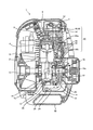
図1は、刈払機に用いられる4サイクルエンジンの正面側の断面図、図2は側面側の断面図である。
図1および図2に示すように、4サイクルエンジン1は、シリンダブロック2にピストン4を往復動自在に収容している。このシリンダブロック2の長手方向の一端側(図中上方)にはシリンダヘッド6が一体的に設けられており、これらシリンダブロック2、シリンダヘッド6およびピストン4の上面によって燃焼室8が形成される。
シリンダブロック2の長手方向の他端側(図中下方)には、オイルパン10が固定されており、シリンダブロック2とオイルパン10とによってクランクケース12が構成されている。
図1および図2に示すように、4サイクルエンジン1は、シリンダブロック2にピストン4を往復動自在に収容している。このシリンダブロック2の長手方向の一端側(図中上方)にはシリンダヘッド6が一体的に設けられており、これらシリンダブロック2、シリンダヘッド6およびピストン4の上面によって燃焼室8が形成される。
シリンダブロック2の長手方向の他端側(図中下方)には、オイルパン10が固定されており、シリンダブロック2とオイルパン10とによってクランクケース12が構成されている。
このクランクケース12の内部にはクランク室14が形成されており、このクランク室14から両端が突出するようにクランクシャフト16が回転自在に支持されている。このクランクシャフト16は、コンロッド18によってピストン4に連結されており、ピストン4の往復運動がコンロッド18を介してクランクシャフト16の回転運動に変換される。
なお、クランクケース12の内部には、各機関を潤滑するための潤滑油を貯留するための油溜室20が設けられている。この油溜室20は、図示のようにシリンダブロック2に形成された仕切壁2aによってクランク室14から仕切られ、密閉された空間となっている。これにより、刈払機のような携帯式の作業機において、使用の際に天地が逆になったり横向きになったりしても、油溜室20から潤滑油が飛散しない。
なお、クランクケース12の内部には、各機関を潤滑するための潤滑油を貯留するための油溜室20が設けられている。この油溜室20は、図示のようにシリンダブロック2に形成された仕切壁2aによってクランク室14から仕切られ、密閉された空間となっている。これにより、刈払機のような携帯式の作業機において、使用の際に天地が逆になったり横向きになったりしても、油溜室20から潤滑油が飛散しない。
また、図2に示すように、クランクケース12には連通路22が形成されている。この連通路22は、一端を油溜室20に開口させ、他端をクランク室14においてクランクシャフト16の周囲に臨ませている。連通路22における油溜室20側の開口には、可撓性を有するパイプ24が接続されている。パイプ24の先端には錘26が設けられており、4サイクルエンジン1が傾いたとしても、潤滑油の液面の変位にパイプ24が追従して、油溜室20内の潤滑油を確実に吸入することができる。
また、クランクシャフト16には、その回転過程で連通路22とクランク室14とを連通する潤滑油路16aが形成されており、クランク室14に生じる負圧作用によって、油溜室20内の潤滑油が、パイプ24、連通路22および潤滑油路16aを介してクランク室14に導かれる。クランク室14に導かれた潤滑油は、クランクシャフト16の回転によって主にクランクウェッブ等から方々に飛散し、ピストン4やクランク室14内の各種の部品を潤滑する。このとき、クランク室14内に飛散した潤滑油は、その一部がミスト化されて、図中符号aで示す潤滑油路を介して後述する側室50や動弁室52に導かれ、これによって側室50や動弁室52内に設けられた各種の部品も潤滑される。なお、側室50や動弁室52に導かれた潤滑油は、ピストン4の昇降作用によって生じる負圧作用により、図中符号bで示す潤滑油路を介して再びクランク室14内に戻される。そして、仕切壁2aには、クランク室14から油溜室20への潤滑油の流通のみを許容する一方向弁28が設けられている。この一方向弁28は、クランク室14内の昇圧作用によって開弁するとともに、各種の部品を潤滑した潤滑油を油溜室20に戻す。
このように、本実施形態においては、クランクシャフト16を収容するクランク室14の圧力変化によって、油溜室20に貯留される潤滑油を、ピストン4やクランクシャフト16、さらには後述する動弁機構40等の各潤滑対象に導くとともに、各潤滑対象から油溜室20に潤滑油を戻す潤滑系統Aを備えている。
そして、上記シリンダヘッド6には、後述する気化器100で生成された混合気を燃焼室8に導くための吸気ポート30、および燃焼室8で生成された排ガスを排気マフラ32に導くための排気ポート34が形成されている。また、シリンダヘッド6には、燃焼室8に対して吸気ポート30を開閉するための吸気バルブ36および排気ポート34に対して燃焼室8を開閉するための排気バルブ38が設けられている。これら吸気バルブ36および排気バルブ38は、動弁機構40によって開閉する。
図2に示すように、本実施形態においては、動弁機構40をいわゆるOHV型動弁機構としている。この動弁機構40は、主な構成部品としてクランクシャフトギヤ42、カムシャフト44、ロッカーアーム46,48等を有している。クランクシャフトギヤ42およびカムシャフト44は、シリンダブロック2およびクランクケース12に沿って形成される側室50に設けられており、ロッカーアーム46,48は、シリンダヘッド6よりも図中さらに上方に形成される動弁室52に設けられている。
上記のクランクシャフトギヤ42は、側室50においてクランクシャフト16と一体となって回転する。上記のカムシャフト44には、側室50においてクランクシャフトギヤ42と噛み合い、クランクシャフト16の1/2回転でカムシャフト44を回転させるカムシャフトギヤ44aが設けられている。さらに、カムシャフト44には、当該カムシャフト44と一体回転するカム44bが設けられている。このカム44bには、プッシュロッド54の一端が接触しており、カム44bの回転によってプッシュロッド54が長手方向に移動する。プッシュロッド54の他端は、上記のロッカーアーム46,48に接続されており、プッシュロッド54の移動にともなってロッカーアーム46,48は揺動する。そして、ロッカーアーム46,48の揺動によって、それぞれ吸気バルブ36および排気バルブ38が押し下げられ、これによって吸気ポート30および排気ポート34が開閉する。
吸気バルブ36は、ピストン4が上死点から下死点まで移動する吸入工程において開弁する。この吸入工程では、燃焼室8において容積拡大にともなって生じる負圧の作用により、吸気ポート30から燃焼室8内に混合気が吸入することとなる。このように、燃焼室8に吸入される混合気を生成するのが気化器100である。この気化器100は、フューエルタンク56から導かれた燃料を、エアクリーナを通過した空気に混合して混合気を生成している。
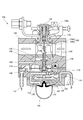
すでに説明したように、使用中に天地が逆になったり横向きになったりするおそれがあることを考慮し、本実施形態においては、いずれの方向でも使用できるように、気化器100をダイヤフラム式の構成としている。以下に、図3を用いて気化器100の構成について説明する。
すでに説明したように、使用中に天地が逆になったり横向きになったりするおそれがあることを考慮し、本実施形態においては、いずれの方向でも使用できるように、気化器100をダイヤフラム式の構成としている。以下に、図3を用いて気化器100の構成について説明する。
図3に示すように、気化器100は気化器本体102を備えている。気化器本体102には、クランク室14に連通するパルス通路104が形成されており、このパルス通路104をポンプダイヤフラム106の一方の側(図中上面)に臨ませている。このポンプダイヤフラム106の他方の側(図中下面)には、ポンプ室108が形成されている。ポンプ室108には、インレットバルブ110を介してフューエルインレット112が連通し、アウトレットバルブ114およびニードルバルブ116を介して貯留室(ダイヤフラム室)118が連通している。なお、フューエルインレット112は、後述する吸入管200および吸入パイプ62を介してフューエルタンク56に接続されている(図1参照)。
クランク室14内では、容積変化にともなって正圧および負圧の交互作用が生じ、この圧力変化がパルス通路104を介してポンプダイヤフラム106に作用する。これにより、ポンプダイヤフラム106は波動運動することとなる。そして、ポンプダイヤフラム106の運動によってポンプ室108側に負圧が作用すると、アウトレットバルブ114が閉じられたままインレットバルブ110が開弁し、フューエルインレット112からポンプ室108に燃料が吸入される。これに対して、ポンプダイヤフラム106の運動によってポンプ室108側に正圧が作用すると、インレットバルブ110が閉じられたままアウトレットバルブ114が開弁し、ポンプ室108から貯留室(ダイヤフラム室)118に燃料が吐出される。
貯留室(ダイヤフラム室)118は、メタリングダイヤフラム120によって背圧室122と区画されている。背圧室122にはエンジンの負圧が作用しており、メタリングダイヤフラム120は、エンジンの負圧と貯留室(ダイヤフラム室)118との圧力差によって作動することとなる。このメタリングダイヤフラム120は、コントロールレバー124を介して上記のニードルバルブ116に接続されており、このメタリングダイヤフラム120の作動によってニードルバルブ116が開閉する。具体的には、貯留室(ダイヤフラム室)118が燃料で一杯になると、貯留室(ダイヤフラム室)118が昇圧し、メタリングダイヤフラム120が背圧室122側に作動する。このとき、コントロールレバースプリング126の弾性力により、コントロールレバー124は、その一端(図中左側)が押し下げられるとともに、他端(図中右側)が押し上げられるように回動する。こうしたコントロールレバー124の回動動作によって、ニードルバルブ116が押し上げられ、ポンプ室108と貯留室(ダイヤフラム室)118の連通が遮断される。
また、気化器本体102には、シリンダヘッド6に形成された吸気ポート30と、不図示のエアクリーナとを接続するための通路128が形成されている。この通路128は、上流側(エアクリーナ側)を大径部128aとし、下流側(吸気ポート30側)を大径部128aよりも小径のベンチュリ部128bとしており、このベンチュリ部128bに、その開度を変位させるスロットルバルブ130が設けられている。このスロットルバルブ130は、その回転軸を通路128に直交させており、回転レバー130aを操作することによって図中上下方向にスライドしながら回転し、その回転量によってベンチュリ部128bの開度が変位するようにしている。
また、このスロットルバルブ130には、アジャスタスクリュ132が設けられている。このアジャスタスクリュ132は、スロットルバルブ130に対して螺子式に止められており、そのスクリュ先端132aを通路128の中心近傍まで延伸させている。アジャスタスクリュ132をスロットルバルブ130に対して一方(締め付け方向)に回転させると、アジャスタスクリュ132のスクリュ先端132aは、図中下方に移動してベンチュリ部128bへの突出量を増す。これとは逆に、アジャスタスクリュ132をスロットルバルブ130に対して他方(戻し方向)に回転させると、アジャスタスクリュ132のスクリュ先端132aは、図中上方に移動してベンチュリ部128bへの突出量を少なくする。
また、気化器本体102には、アジャスタスクリュ132に対向するようにノズル134が設けられており、このノズル134のノズル先端134aに、アジャスタスクリュ132のスクリュ先端132aが挿入されている。
さらに、ノズル134には、通路128に開口する孔134bが形成されており、この孔134bに連通する基端134cを、貯留室(ダイヤフラム室)118に臨ませている。これにより、貯留室(ダイヤフラム室)118と通路128とが、流路135を介して連通する。なお、流路135上には、メインジェット136およびメインチェックバルブ138が設けられている。
さらに、ノズル134には、通路128に開口する孔134bが形成されており、この孔134bに連通する基端134cを、貯留室(ダイヤフラム室)118に臨ませている。これにより、貯留室(ダイヤフラム室)118と通路128とが、流路135を介して連通する。なお、流路135上には、メインジェット136およびメインチェックバルブ138が設けられている。
そして、吸気バルブ36が開くと、スロットルバルブ130の開度に応じた流量の空気が、エアクリーナから吸気ポート30に向かって通路128内を通過する。このとき、ベンチュリ部128bにおいて空気の流速が増し、ノズル134近傍の負圧作用によって、貯留室(ダイヤフラム室)118から流路135を介して燃料が吸い上げられる。貯留室(ダイヤフラム室)118から吸い上げられた燃料は、孔134bから通路128に吸い出される。このようにして混合気が生成され、この混合気が吸気ポート30を介して燃焼室8に導かれる。なお、空気に混合される燃料の量は、スロットルバルブ130の開度すなわち空気の流量に応じて、流路135上に設けられたメインジェット136、孔134bおよびスクリュ先端132aによって構成される流量制御部によって次のように制御される。
まず、回転レバー130aが図3に示す位置にあるときには、図4(a)に示すように、スロットルバルブ130によってベンチュリ部128bの開度が絞られており、僅かな空気が通路128を通過する。この状態が4サイクルエンジン1のアイドル状態となるが、このときに孔134bから吸い出される燃料の量は、アジャスタスクリュ132の回転によって調節することができる。つまり、アジャスタスクリュ132を一方(締め付け方向)に回転させると、スクリュ先端132aがベンチュリ部128bに突出して孔134bの開度が小さくなる。よって、孔134bから吸い出される燃料の量が少なくなり、混合気を薄めることができる。これとは逆に、アジャスタスクリュ132を戻し方向に回転させると、スクリュ先端132aがベンチュリ部128bから退避して孔134bの開度が大きくなる。よって、孔134bから吸い出される燃料の量が多くなり、混合気を濃くすることができる。このように、アジャスタスクリュ132を調節することで、アイドル状態における混合気の濃度を調節することが可能となる。
上記のアイドル状態から回転レバー130aを回転させると、図4(b)に示すように、スロットルバルブ130が回転軸方向にスライドしながら回転し、ベンチュリ部128bの開度が大きくなって、通路128を通過する空気の流量が増す。このとき、スロットルバルブ130と一体となってアジャスタスクリュ132も図3において上方にスライドする。したがって、スクリュ先端132aが上方に引き上げられて孔134bの開度が大きくなり、通路128に吸い出される燃料の量が上記のアイドル状態に比べて多くなる。
そして、上記の状態からさらに回転レバー130aを回転させると、図4(c)に示すように、スロットルバルブ130が回転軸方向にさらにスライドしながら回転し、ベンチュリ部128bの開度が最大となる。また、スクリュ先端132aがさらに上方に引き上げられるため、孔134bの開度もさらに大きくなるが、このときに通路128に吸い出される燃料の量はメインジェット136の径によって制御される。
ここで、メインジェット136の開口径は、スロットルバルブ130によって通路128が全開となった状態で、混合気の質量に占める燃料の質量の割合が10%前後の範囲、望ましくは8.5%~14%の範囲に収まるように設定されている。これは、100%エタノールを燃料とした場合の理論空燃比が、空気:燃料(エタノール)=9:1であることを考慮したものである。ただし、エタノールは親水性が強く、エタノール100%の燃料とはいっても、実際には燃料中に水分が含まれてしまう。したがって、最大出力を確実に確保するといった観点からすれば、混合気の質量に占める燃料の質量の割合が10%以上(高濃度)になるようにメインジェット136の開口径を設定する方が望ましい。
ここで、メインジェット136の開口径は、スロットルバルブ130によって通路128が全開となった状態で、混合気の質量に占める燃料の質量の割合が10%前後の範囲、望ましくは8.5%~14%の範囲に収まるように設定されている。これは、100%エタノールを燃料とした場合の理論空燃比が、空気:燃料(エタノール)=9:1であることを考慮したものである。ただし、エタノールは親水性が強く、エタノール100%の燃料とはいっても、実際には燃料中に水分が含まれてしまう。したがって、最大出力を確実に確保するといった観点からすれば、混合気の質量に占める燃料の質量の割合が10%以上(高濃度)になるようにメインジェット136の開口径を設定する方が望ましい。
ただし、メインジェット136の開口径をあまり大きくし過ぎると、今度は混合気中に不必要に燃料が混合されてしまうので、実際は、混合気の質量に占める燃料の質量の割合が8.5%以上かつ14%以下、より理想的には空気:燃料(エタノール)が7:1~9:1の範囲内になるように設定することが望ましい。
このことからも明らかなように、本実施形態においては、容積のほぼ100%がエタノールで構成される燃料を最適燃料としており、この最適燃料を用いることによって、従来のガソリンを燃料とする作業機用エンジンに比べて、環境への悪影響を低減しながらも同等の出力を実現することが可能となる。
また、本実施形態においては、図4(a)や図4(b)に示す状態でも、空気:燃料(エタノール)=7:1~9:1となるように、孔134bの開口量とスクリュ先端132aの突出量とが設定されている。ただし、常に空気:燃料(エタノール)=7:1~9:1(混合気の質量に占める燃料の質量の割合が8.5%以上かつ14%以下)となるように設定する必要はなく、例えば、図4(c)に示す高出力状態においてのみ、混合気の質量に占める燃料の質量の割合が10%前後となり、図4(a)や図4(b)に示す状態では、混合気中に占める燃料の割合が少なく(薄く)または多く(濃く)なるようにしてもよい。
このことからも明らかなように、本実施形態においては、容積のほぼ100%がエタノールで構成される燃料を最適燃料としており、この最適燃料を用いることによって、従来のガソリンを燃料とする作業機用エンジンに比べて、環境への悪影響を低減しながらも同等の出力を実現することが可能となる。
また、本実施形態においては、図4(a)や図4(b)に示す状態でも、空気:燃料(エタノール)=7:1~9:1となるように、孔134bの開口量とスクリュ先端132aの突出量とが設定されている。ただし、常に空気:燃料(エタノール)=7:1~9:1(混合気の質量に占める燃料の質量の割合が8.5%以上かつ14%以下)となるように設定する必要はなく、例えば、図4(c)に示す高出力状態においてのみ、混合気の質量に占める燃料の質量の割合が10%前後となり、図4(a)や図4(b)に示す状態では、混合気中に占める燃料の割合が少なく(薄く)または多く(濃く)なるようにしてもよい。
なお、図3に示すように、気化器本体102には、手動で圧縮および膨張が可能に構成され、その操作によって貯留室(ダイヤフラム室)118に負圧を生じさせるプライマポンプ140が設けられている。このプライマポンプ140を操作すると、貯留室(ダイヤフラム室)118が負圧になるため、フューエルタンク56から貯留室(ダイヤフラム室)118内に燃料が吸い上げられる。このとき、メインチェックバルブ138は、ノズル134を介して通路128から貯留室(ダイヤフラム室)118へ空気が流入するのを防ぐように機能する。そして、吸い上げられた燃料は貯留室(ダイヤフラム室)118からオーバーフローパイプ142を介してフューエルタンク56に戻される。
ここで、図1に示すように、気化器100とフューエルタンク56とは、吸入管200および戻り管202によって接続されている。
より具体的には、フューエルタンク56は、断面を略コ字形に形成されており、クランクケース12を覆うように配置されている。フューエルタンク56において、気化器100と対面する部分にはキャップ嵌め込み孔58が形成されており、このキャップ嵌め込み孔58にキャップ60が嵌め込まれている。キャップ60は、戻り管202を圧入固定した状態で貫通させている。戻り管202は、一端を気化器100のオーバーフローパイプ142に圧入固定され、他端をフューエルタンク56内に位置させている。これにより、プライマポンプ140の操作によって貯留室(ダイヤフラム室)118に吸い上げられた燃料は、オーバーフローパイプ142および戻り管202を介してフューエルタンク56に戻される。
より具体的には、フューエルタンク56は、断面を略コ字形に形成されており、クランクケース12を覆うように配置されている。フューエルタンク56において、気化器100と対面する部分にはキャップ嵌め込み孔58が形成されており、このキャップ嵌め込み孔58にキャップ60が嵌め込まれている。キャップ60は、戻り管202を圧入固定した状態で貫通させている。戻り管202は、一端を気化器100のオーバーフローパイプ142に圧入固定され、他端をフューエルタンク56内に位置させている。これにより、プライマポンプ140の操作によって貯留室(ダイヤフラム室)118に吸い上げられた燃料は、オーバーフローパイプ142および戻り管202を介してフューエルタンク56に戻される。
また、キャップ60は、吸入パイプ62を圧入固定した状態で貫通させている。この吸入パイプ62は可撓性を有するものであり、一方の端部62aは、後述する接続部材204を介して吸入管200に接続され、他方の端部62bは、フューエルタンク56内に位置している。吸入パイプ62は、戻り管202に比べて長く、フューエルタンク56の奥にまで進入可能としている。また、吸入パイプ62の端部62bには、燃料内の不純物を取り除くための1次フィルタ64が設けられており、気化器100に燃料が導かれる際に、吸入パイプ62に不純物が進入しないようにしている。1次フィルタ64の周囲には錘66が設けられており、4サイクルエンジン1が傾いたとしても、燃料の液面の変位に吸入パイプ62が追従するようにしている。これにより、4サイクルエンジン1がいずれの方向に傾いた場合にも、フューエルタンク56内の燃料が確実に吸入される。
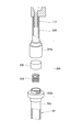
吸入パイプ62および吸入管200は、図5に示すように、接続部材204を介して接続される。すなわち、接続部材204は、中空の筒体204aと、この筒体204aに螺子止めによって固定される蓋体204bとによって構成される。筒体204aには、圧入や接着剤等によって吸入管200が固定されており、これと同様に、蓋体204bには、吸入パイプ62の端部62aが固定されている。蓋体204bには貫通孔が形成されており、この蓋体204bを筒体204aに螺子止めすることにより、吸入パイプ62と吸入管200とが連通する。
また、筒体204a内には、2次フィルタ206と、この2次フィルタ206を蓋体204b側から筒体204a側に押し付けるためのスプリング208とが設けられている。2次フィルタ206の側面の面積は、吸入管200の開口面積よりも大きく、スプリング208の弾性力によって2次フィルタ206が吸入管200の開口部全面に押し付けられることにより、吸入される燃料が確実に2次フィルタ206を通過する。
また、筒体204a内には、2次フィルタ206と、この2次フィルタ206を蓋体204b側から筒体204a側に押し付けるためのスプリング208とが設けられている。2次フィルタ206の側面の面積は、吸入管200の開口面積よりも大きく、スプリング208の弾性力によって2次フィルタ206が吸入管200の開口部全面に押し付けられることにより、吸入される燃料が確実に2次フィルタ206を通過する。
この2次フィルタ206は、バイオマスエタノールの生成過程で分解されずに残留してしまった物質(例えば、セルロース類。以下、「非分解物質」という)の除去を目的とするものである。つまり、フューエルタンク56から気化器100に燃料が導かれる過程では、まず、1次フィルタ64によって燃料中に混入したゴミ等の不純物が除去される。1次フィルタ64によって不純物が除去された燃料は、さらに2次フィルタ206を通過することとなるが、この2次フィルタ206を燃料が通過する過程で、燃料(バイオマスエタノール)中に含まれる非分解物質が除去される。本実施形態においては、2次フィルタ206として、微細な濾過孔が形成され、かつ、燃料の流通方向に立体的に繊維体が入り組む性質を有する金属繊維を用いているが、耐熱性、耐食性等を考慮するとステンレス鋼繊維を用いることがより望ましい。
上記のように、1次フィルタ64と2次フィルタ206とによって、燃料中の不純物を段階的に除去する本実施形態によれば、気化器100への燃料の流通がすぐに阻害されたり、フィルタを頻繁に交換または洗浄したりしなければならないといった煩わしさを生じることなく、確実に不純物を除去することが可能となる。
すなわち、1次フィルタ64によって除去することができなかったセルロース類等の非分解物質を、2次フィルタ206によって除去することができる。
気化器100においては、理論空燃比を実現するために、メインジェット136やノズル134の径を詳細に設計する必要があるが、こうした部位にセルロース類等の非分解物質が付着し続けると径が小さくなってしまい、理論空燃比を実現できなくなってしまう。本実施形態のように、不純物の付着によって影響が及ぼされる部位よりも上流側に2次フィルタ206を設けることにより、こうした特段の問題が生じるのを防ぐことが可能となる。
すなわち、1次フィルタ64によって除去することができなかったセルロース類等の非分解物質を、2次フィルタ206によって除去することができる。
気化器100においては、理論空燃比を実現するために、メインジェット136やノズル134の径を詳細に設計する必要があるが、こうした部位にセルロース類等の非分解物質が付着し続けると径が小さくなってしまい、理論空燃比を実現できなくなってしまう。本実施形態のように、不純物の付着によって影響が及ぼされる部位よりも上流側に2次フィルタ206を設けることにより、こうした特段の問題が生じるのを防ぐことが可能となる。
なお、1次フィルタ64も2次フィルタ206と同様の材質で構成し、非分解物質を1次フィルタ64においても除去するようにしても構わない。ただし、1次フィルタ64によってセルロース類等の非分解物質と他の物質とをまとめて除去しようとすると、1次フィルタ64が目詰まりを生じやすくなるおそれがある。そのため、1次フィルタ64の濾過孔を2次フィルタ206の濾過孔に比べて粗くするとともに、1次フィルタ64によって、主に非分解物質よりも大きな不純物を除去し、非分解物質は主に2次フィルタ206によって除去するようにすることがより望ましい。
このようにした場合には、2次フィルタ206は、1次フィルタ64に比べて濾過孔が微細であるため、交換や洗浄の頻度が多くなる可能性がある。そこで、本実施形態によれば、2次フィルタ206の交換や洗浄の頻度を考慮して、フューエルタンク56と気化器100との流通過程、より詳細には、フューエルタンク56の外方であって、しかも、気化器本体102の外方に着脱容易に2次フィルタ206を設けるようにしている。つまり、2次フィルタ206は、1次フィルタ64よりも下流であって、混合気が生成される前に燃料を濾過することができる位置であれば、その配置や段階は特に限定されない。したがって、2次フィルタ206はフューエルタンク56内に設けてもよいし、気化器100内に設けてもよい。
しかしながら、上記のように交換や洗浄の頻度が高くなるおそれがある2次フィルタ206を、気化器本体102やフューエルタンク56等、他の部品の内部に設けてしまうと、その交換作業や洗浄作業が煩雑になってしまう。本実施形態のように、フューエルタンク56の外方であって、しかも、気化器本体102の外方に着脱容易に2次フィルタ206を設ければ、交換作業や洗浄作業が容易となり、上記のような煩雑さを解消することができる。
しかしながら、上記のように交換や洗浄の頻度が高くなるおそれがある2次フィルタ206を、気化器本体102やフューエルタンク56等、他の部品の内部に設けてしまうと、その交換作業や洗浄作業が煩雑になってしまう。本実施形態のように、フューエルタンク56の外方であって、しかも、気化器本体102の外方に着脱容易に2次フィルタ206を設ければ、交換作業や洗浄作業が容易となり、上記のような煩雑さを解消することができる。
なお、作業機用のエンジンにおける各部品の潤滑方法として、燃料中に潤滑油を混入させ、燃料とともに潤滑油を各部品に供給する方法が考えられる。しかしながら、ガソリンを含有していないエタノールのみの燃料を用いる場合には、エタノールと潤滑油とが分離してしまい、潤滑油を各潤滑対象に確実に導くことができなくなってしまうおそれがある。そこで、本実施形態においては、燃料系統とは完全に分離した潤滑系統Aを設け、主にクランク室14の圧力変化によって各潤滑対象に潤滑油を供給するようにしている。このように、燃料系統と潤滑系統とを完全に分離させることにより、ガソリンを含有していない燃料であっても、確実に潤滑対象を潤滑することが可能となる。
以上のように、本実施形態によれば、エタノールを燃料として用いることにより、従来のガソリンを燃料とする作業機用のエンジンに比べて環境に及ぼす影響が小さくなる。
以上のように、本実施形態によれば、エタノールを燃料として用いることにより、従来のガソリンを燃料とする作業機用のエンジンに比べて環境に及ぼす影響が小さくなる。
なお、本実施形態においては、本発明を4サイクルエンジンに適用した場合について説明したが、本発明は2サイクルエンジンにも適用可能である。
また、本発明を適用可能な作業機は、クランクシャフト16に接続されて、クランクシャフト16の回転動力によって作動するもの全てが含まれる。
また、本実施形態におけるフューエルタンク56や気化器100、あるいはピストン4やクランクシャフト16といった燃焼系や駆動系等の各構成部品の形状や配置等は一例に過ぎず、本実施形態の構成に限定されるものではない。
また、本実施形態においては、2次フィルタ206を金属鋼線によって構成したが、濾過孔の大きさ等、バイオエタノールの生成過程で分解されずに残留してしまう物質を除去することができるものであれば、その材質や形状等は特に限定されない。
また、本実施形態においては、特に1次フィルタ64と2次フィルタ206との関係について説明したが、フィルタは2つに限らず、3つ以上設けることとしても構わない。いずれにしても、多段階にフィルタを設けた場合には、非分解物質を、少なくとも上流側から2つ目以降の1つまたは2以上のフィルタによって除去することができればよい。
また、本発明を適用可能な作業機は、クランクシャフト16に接続されて、クランクシャフト16の回転動力によって作動するもの全てが含まれる。
また、本実施形態におけるフューエルタンク56や気化器100、あるいはピストン4やクランクシャフト16といった燃焼系や駆動系等の各構成部品の形状や配置等は一例に過ぎず、本実施形態の構成に限定されるものではない。
また、本実施形態においては、2次フィルタ206を金属鋼線によって構成したが、濾過孔の大きさ等、バイオエタノールの生成過程で分解されずに残留してしまう物質を除去することができるものであれば、その材質や形状等は特に限定されない。
また、本実施形態においては、特に1次フィルタ64と2次フィルタ206との関係について説明したが、フィルタは2つに限らず、3つ以上設けることとしても構わない。いずれにしても、多段階にフィルタを設けた場合には、非分解物質を、少なくとも上流側から2つ目以降の1つまたは2以上のフィルタによって除去することができればよい。
4 ピストン
8 燃焼室
14 クランク室
16 クランクシャフト
56 フューエルタンク
100 気化器
118 貯留室(ダイヤフラム室)
128 通路
130 スロットルバルブ
132 アジャスタスクリュ
132a スクリュ先端
134b 孔
135 流路
136 メインジェット
A 潤滑系統
a,b 潤滑油路
8 燃焼室
14 クランク室
16 クランクシャフト
56 フューエルタンク
100 気化器
118 貯留室(ダイヤフラム室)
128 通路
130 スロットルバルブ
132 アジャスタスクリュ
132a スクリュ先端
134b 孔
135 流路
136 メインジェット
A 潤滑系統
a,b 潤滑油路
Claims (4)
- 混合気を吸入して爆発させるための燃焼室と、
前記燃焼室で発生する爆発圧力によって往復動するピストンと、
前記ピストンに連係され、前記ピストンの往復運動を回転運動に変換して出力するためのクランクシャフトと、
容積の90%以上がエタノールで構成される燃料を貯留するためのフューエルタンクと、
前記燃焼室の負圧作用によって当該燃焼室に吸入される空気中に前記燃料を混合するとともに、少なくとも前記空気の流量が最大となるときに質量の8.5%以上を前記燃料で占める前記混合気を生成するための混合気生成手段と、を備えた作業機用エンジン。 - 前記混合気生成手段は、前記燃料の占める割合が質量の14%以下の混合気を生成する請求項1記載の作業機用エンジン。
- 前記混合気生成手段は、
前記燃焼室に連通するための通路と、
前記通路の開度を調整して空気の流量を変化させるためのスロットルバルブと、
前記フューエルタンクから導かれた前記燃料を一時的に貯留するための貯留室と、
前記貯留室と前記通路とを連通し、前記通路内を空気が流通したときに前記貯留室から前記通路まで前記燃料を導くための流路と、
前記流路上に設けられ、前記スロットルバルブの開度調整に応じて前記燃料の流量を制御するとともに、少なくとも前記スロットルバルブによって前記通路が全開となった状態で、前記通路を流通する空気の質量に対して、前記流路を流通する燃料の質量を8.5%~14%に制御するための流量制御部と、を備えた気化器からなる請求項1または2に記載の作業機用エンジン。 - 前記クランクシャフトを収容するクランク室に連通し、潤滑油を貯留するための油溜室と、
前記クランクシャフトを収容するためのクランク室と潤滑対象とを連通するための潤滑油路と、を有する潤滑系統を備え、
前記潤滑系統は、前記クランク室の圧力変化によって、前記油溜室に貯留される潤滑油を、前記潤滑油路を介して潤滑対象に導くとともに、各潤滑対象から前記油溜室に潤滑油を戻す請求項1~3のいずれかに記載の作業機用エンジン。
Applications Claiming Priority (2)
| Application Number | Priority Date | Filing Date | Title |
|---|---|---|---|
| JP2009292054A JP2011132856A (ja) | 2009-12-24 | 2009-12-24 | 作業機用エンジン |
| JP2009-292054 | 2009-12-24 |
Publications (1)
| Publication Number | Publication Date |
|---|---|
| WO2011077907A1 true WO2011077907A1 (ja) | 2011-06-30 |
Family
ID=44195445
Family Applications (1)
| Application Number | Title | Priority Date | Filing Date |
|---|---|---|---|
| PCT/JP2010/071406 Ceased WO2011077907A1 (ja) | 2009-12-24 | 2010-11-30 | 作業機用エンジン |
Country Status (2)
| Country | Link |
|---|---|
| JP (1) | JP2011132856A (ja) |
| WO (1) | WO2011077907A1 (ja) |
Cited By (1)
| Publication number | Priority date | Publication date | Assignee | Title |
|---|---|---|---|---|
| CN103867343A (zh) * | 2012-12-10 | 2014-06-18 | 陈俭敏 | 一种化油器及其取油结构 |
Families Citing this family (2)
| Publication number | Priority date | Publication date | Assignee | Title |
|---|---|---|---|---|
| JP2016211510A (ja) * | 2015-05-13 | 2016-12-15 | 株式会社マキタ | エンジン装置および携帯型作業機 |
| JP7711024B2 (ja) * | 2022-03-30 | 2025-07-22 | 東海化成工業株式会社 | 内装部材 |
Citations (4)
| Publication number | Priority date | Publication date | Assignee | Title |
|---|---|---|---|---|
| JPH03117664A (ja) * | 1989-09-29 | 1991-05-20 | Fuji Heavy Ind Ltd | アルコールエンジンの燃料噴射制御装置 |
| JP2004251231A (ja) * | 2003-02-21 | 2004-09-09 | Fuji Robin Ind Ltd | 4サイクルエンジンの潤滑装置 |
| JP2008082171A (ja) * | 2006-09-25 | 2008-04-10 | Honda Motor Co Ltd | 多種類燃料エンジン用燃料噴射制御装置 |
| JP2009281216A (ja) * | 2008-05-21 | 2009-12-03 | Toyota Motor Corp | 内燃機関の制御装置 |
-
2009
- 2009-12-24 JP JP2009292054A patent/JP2011132856A/ja active Pending
-
2010
- 2010-11-30 WO PCT/JP2010/071406 patent/WO2011077907A1/ja not_active Ceased
Patent Citations (4)
| Publication number | Priority date | Publication date | Assignee | Title |
|---|---|---|---|---|
| JPH03117664A (ja) * | 1989-09-29 | 1991-05-20 | Fuji Heavy Ind Ltd | アルコールエンジンの燃料噴射制御装置 |
| JP2004251231A (ja) * | 2003-02-21 | 2004-09-09 | Fuji Robin Ind Ltd | 4サイクルエンジンの潤滑装置 |
| JP2008082171A (ja) * | 2006-09-25 | 2008-04-10 | Honda Motor Co Ltd | 多種類燃料エンジン用燃料噴射制御装置 |
| JP2009281216A (ja) * | 2008-05-21 | 2009-12-03 | Toyota Motor Corp | 内燃機関の制御装置 |
Cited By (1)
| Publication number | Priority date | Publication date | Assignee | Title |
|---|---|---|---|---|
| CN103867343A (zh) * | 2012-12-10 | 2014-06-18 | 陈俭敏 | 一种化油器及其取油结构 |
Also Published As
| Publication number | Publication date |
|---|---|
| JP2011132856A (ja) | 2011-07-07 |
Similar Documents
| Publication | Publication Date | Title |
|---|---|---|
| US20100326412A1 (en) | Carburetor and Two-Stroke Engine with a Carburetor | |
| WO2011077907A1 (ja) | 作業機用エンジン | |
| JP5377264B2 (ja) | 作業機用エンジン | |
| CN102678388B (zh) | 发动机 | |
| US6668770B2 (en) | Two-stroke interal combustion engine | |
| JP2011127502A (ja) | 作業機用エンジン | |
| WO2011074405A1 (ja) | 作業機用エンジン | |
| JP4187109B2 (ja) | 空気・燃料混合気噴射式内燃機関 | |
| US10273843B2 (en) | Lubricating structure for four-stroke engine | |
| CN106567757B (zh) | 发动机的润滑装置 | |
| JP2015094216A (ja) | エンジンの燃料供給装置及び運転方法 | |
| CN209942904U (zh) | 小型发动机定向脉冲润滑结构 | |
| US6830030B2 (en) | Four-cycle engine | |
| CN102644525A (zh) | 化油器 | |
| JP6345549B2 (ja) | エンジンの吸気装置 | |
| JP7689915B2 (ja) | キャブレタアッセンブリ | |
| JP4327041B2 (ja) | 4サイクルエンジン | |
| JPH06346718A (ja) | 4サイクルエンジンの潤滑装置 | |
| JPH06146837A (ja) | 4サイクルエンジンの潤滑装置 | |
| JPH0633723A (ja) | 2行程機関の分離給油装置 | |
| US7287495B1 (en) | Two-cycle engine | |
| JP2017053234A (ja) | エンジンの燃料供給装置 | |
| JP5961468B2 (ja) | エンジン | |
| JPS6123639Y2 (ja) | ||
| JP2003293774A (ja) | 2サイクルエンジン |
Legal Events
| Date | Code | Title | Description |
|---|---|---|---|
| 121 | Ep: the epo has been informed by wipo that ep was designated in this application |
Ref document number: 10839142 Country of ref document: EP Kind code of ref document: A1 |
|
| NENP | Non-entry into the national phase |
Ref country code: DE |
|
| 122 | Ep: pct application non-entry in european phase |
Ref document number: 10839142 Country of ref document: EP Kind code of ref document: A1 |