WO2011077677A1 - 情報処理装置及びスイッチ装置 - Google Patents
情報処理装置及びスイッチ装置 Download PDFInfo
- Publication number
- WO2011077677A1 WO2011077677A1 PCT/JP2010/007316 JP2010007316W WO2011077677A1 WO 2011077677 A1 WO2011077677 A1 WO 2011077677A1 JP 2010007316 W JP2010007316 W JP 2010007316W WO 2011077677 A1 WO2011077677 A1 WO 2011077677A1
- Authority
- WO
- WIPO (PCT)
- Prior art keywords
- unit
- movable
- switch
- positions
- information processing
- Prior art date
- Legal status (The legal status is an assumption and is not a legal conclusion. Google has not performed a legal analysis and makes no representation as to the accuracy of the status listed.)
- Ceased
Links
Images







Classifications
-
- H—ELECTRICITY
- H01—ELECTRIC ELEMENTS
- H01H—ELECTRIC SWITCHES; RELAYS; SELECTORS; EMERGENCY PROTECTIVE DEVICES
- H01H25/00—Switches with compound movement of handle or other operating part
- H01H25/002—Switches with compound movement of handle or other operating part having an operating member rectilinearly slidable in different directions
-
- H—ELECTRICITY
- H01—ELECTRIC ELEMENTS
- H01H—ELECTRIC SWITCHES; RELAYS; SELECTORS; EMERGENCY PROTECTIVE DEVICES
- H01H25/00—Switches with compound movement of handle or other operating part
-
- G—PHYSICS
- G06—COMPUTING OR CALCULATING; COUNTING
- G06F—ELECTRIC DIGITAL DATA PROCESSING
- G06F1/00—Details not covered by groups G06F3/00 - G06F13/00 and G06F21/00
- G06F1/16—Constructional details or arrangements
-
- G—PHYSICS
- G06—COMPUTING OR CALCULATING; COUNTING
- G06F—ELECTRIC DIGITAL DATA PROCESSING
- G06F1/00—Details not covered by groups G06F3/00 - G06F13/00 and G06F21/00
- G06F1/16—Constructional details or arrangements
- G06F1/1601—Constructional details related to the housing of computer displays, e.g. of CRT monitors, of flat displays
-
- G—PHYSICS
- G06—COMPUTING OR CALCULATING; COUNTING
- G06F—ELECTRIC DIGITAL DATA PROCESSING
- G06F1/00—Details not covered by groups G06F3/00 - G06F13/00 and G06F21/00
- G06F1/16—Constructional details or arrangements
- G06F1/1613—Constructional details or arrangements for portable computers
-
- G—PHYSICS
- G06—COMPUTING OR CALCULATING; COUNTING
- G06F—ELECTRIC DIGITAL DATA PROCESSING
- G06F1/00—Details not covered by groups G06F3/00 - G06F13/00 and G06F21/00
- G06F1/16—Constructional details or arrangements
- G06F1/1613—Constructional details or arrangements for portable computers
- G06F1/1615—Constructional details or arrangements for portable computers with several enclosures having relative motions, each enclosure supporting at least one I/O or computing function
- G06F1/1616—Constructional details or arrangements for portable computers with several enclosures having relative motions, each enclosure supporting at least one I/O or computing function with folding flat displays, e.g. laptop computers or notebooks having a clamshell configuration, with body parts pivoting to an open position around an axis parallel to the plane they define in closed position
-
- G—PHYSICS
- G06—COMPUTING OR CALCULATING; COUNTING
- G06F—ELECTRIC DIGITAL DATA PROCESSING
- G06F1/00—Details not covered by groups G06F3/00 - G06F13/00 and G06F21/00
- G06F1/26—Power supply means, e.g. regulation thereof
-
- G—PHYSICS
- G06—COMPUTING OR CALCULATING; COUNTING
- G06F—ELECTRIC DIGITAL DATA PROCESSING
- G06F1/00—Details not covered by groups G06F3/00 - G06F13/00 and G06F21/00
- G06F1/26—Power supply means, e.g. regulation thereof
- G06F1/32—Means for saving power
- G06F1/3203—Power management, i.e. event-based initiation of a power-saving mode
-
- G—PHYSICS
- G06—COMPUTING OR CALCULATING; COUNTING
- G06F—ELECTRIC DIGITAL DATA PROCESSING
- G06F1/00—Details not covered by groups G06F3/00 - G06F13/00 and G06F21/00
- G06F1/26—Power supply means, e.g. regulation thereof
- G06F1/32—Means for saving power
- G06F1/3203—Power management, i.e. event-based initiation of a power-saving mode
- G06F1/3234—Power saving characterised by the action undertaken
- G06F1/3287—Power saving characterised by the action undertaken by switching off individual functional units in the computer system
-
- G—PHYSICS
- G06—COMPUTING OR CALCULATING; COUNTING
- G06F—ELECTRIC DIGITAL DATA PROCESSING
- G06F1/00—Details not covered by groups G06F3/00 - G06F13/00 and G06F21/00
- G06F1/26—Power supply means, e.g. regulation thereof
- G06F1/32—Means for saving power
- G06F1/3203—Power management, i.e. event-based initiation of a power-saving mode
- G06F1/3234—Power saving characterised by the action undertaken
- G06F1/3293—Power saving characterised by the action undertaken by switching to a less power-consuming processor, e.g. sub-CPU
-
- H—ELECTRICITY
- H01—ELECTRIC ELEMENTS
- H01H—ELECTRIC SWITCHES; RELAYS; SELECTORS; EMERGENCY PROTECTIVE DEVICES
- H01H25/00—Switches with compound movement of handle or other operating part
- H01H25/006—Switches with compound movement of handle or other operating part having an operating member slidable in a plane in one direction and pivotable around an axis located in the sliding plane perpendicular to the sliding direction
-
- H—ELECTRICITY
- H01—ELECTRIC ELEMENTS
- H01H—ELECTRIC SWITCHES; RELAYS; SELECTORS; EMERGENCY PROTECTIVE DEVICES
- H01H9/00—Details of switching devices, not covered by groups H01H1/00 - H01H7/00
- H01H9/16—Indicators for switching condition, e.g. "on" or "off"
- H01H9/161—Indicators for switching condition, e.g. "on" or "off" comprising light emitting elements
-
- H—ELECTRICITY
- H01—ELECTRIC ELEMENTS
- H01H—ELECTRIC SWITCHES; RELAYS; SELECTORS; EMERGENCY PROTECTIVE DEVICES
- H01H15/00—Switches having rectilinearly-movable operating part or parts adapted for actuation in opposite directions, e.g. slide switch
- H01H15/02—Details
- H01H15/025—Light-emitting indicators
-
- H—ELECTRICITY
- H01—ELECTRIC ELEMENTS
- H01H—ELECTRIC SWITCHES; RELAYS; SELECTORS; EMERGENCY PROTECTIVE DEVICES
- H01H15/00—Switches having rectilinearly-movable operating part or parts adapted for actuation in opposite directions, e.g. slide switch
- H01H15/02—Details
- H01H15/06—Movable parts; Contacts mounted thereon
- H01H15/10—Operating parts
- H01H15/102—Operating parts comprising cam devices
- H01H15/107—Operating parts comprising cam devices actuating conventional selfcontained microswitches
-
- Y—GENERAL TAGGING OF NEW TECHNOLOGICAL DEVELOPMENTS; GENERAL TAGGING OF CROSS-SECTIONAL TECHNOLOGIES SPANNING OVER SEVERAL SECTIONS OF THE IPC; TECHNICAL SUBJECTS COVERED BY FORMER USPC CROSS-REFERENCE ART COLLECTIONS [XRACs] AND DIGESTS
- Y02—TECHNOLOGIES OR APPLICATIONS FOR MITIGATION OR ADAPTATION AGAINST CLIMATE CHANGE
- Y02D—CLIMATE CHANGE MITIGATION TECHNOLOGIES IN INFORMATION AND COMMUNICATION TECHNOLOGIES [ICT], I.E. INFORMATION AND COMMUNICATION TECHNOLOGIES AIMING AT THE REDUCTION OF THEIR OWN ENERGY USE
- Y02D10/00—Energy efficient computing, e.g. low power processors, power management or thermal management
Definitions
- the present invention relates to an information processing device and a switch device including a switch unit.
- Patent Document 1 An electronic device capable of executing a plurality of modes and capable of switching between the plurality of modes using a switch unit is provided (see, for example, Patent Document 1).
- the electronic device of Patent Document 1 is provided with a slide knob that can slide over three mode positions provided on a straight line. By sliding the slide knob to a desired mode position, the mode can be switched according to the mode position.
- the electronic device has an engagement means for restricting further movement of the slide knob to the mode position at the other end in the sliding direction when the slide knob is moved from the mode position at one end in the sliding direction to the intermediate mode position. Furthermore, it is provided. Thereby, a mode switching mistake can be prevented.
- the size of the entire switch may increase.
- an object of the present invention is to provide a small switch unit that can move a movable unit directly to a desired position, and a plurality of operation states can be switched easily and reliably by this switch unit. Is to provide a simple information processing apparatus. Another object of the present invention is to provide a small switch device capable of directly moving a movable part to a desired position.
- an information processing apparatus includes a switch unit and a control unit.
- the switch unit includes a movable unit, a support unit, and a detection unit.
- the movable part can be operated by a user.
- the support portion supports the movable portion so as to be directly movable between two positions in all combinations at three or more positions.
- the said detection part detects that the said movable part moved to each said position.
- the control unit recognizes a detection result of the detection unit.
- the movable part can be moved directly to each other position. This facilitates the switch switching operation by the user and simplifies the configuration of the control unit that recognizes the user's switch switching operation based on the detection result of the position where the movable unit has moved.
- the switch unit may further include a localization unit that localizes the movable unit at each position.
- the switch unit is provided between each of the two positions. In the process in which the movable unit moves between the two positions, the switch unit interferes with the movable unit at different timings to cause the movable unit to move. You may further have an engaging part which has the 1st taper surface to regulate, and the 2nd taper surface which accelerates
- the switch unit may further include an urging unit that urges the taper surface of the engagement portion and the movable portion to come into pressure contact with each other.
- the movable portion pushes down the first tapered surface while resisting the urging force of the urging means at the position of interference with the first tapered surface. Accordingly, during this time, the user feels resistance in the moving operation of the movable part. This sense of resistance sharply decreases when the movable part leaves the first tapered surface. Such a change in resistance is given to the user as a click feeling.
- the movable portion reaches the position of interference with the second tapered surface, the movable portion is pulled along the second tapered surface by the urging force of the urging means, and as a result, the movement of the movable portion is promoted.
- An operation in which the movable portion is guided by the urging force of the urging means and the taper action of the second taper surface is given to the user as a feeling of retraction.
- the control unit may switch the operation state of the information processing apparatus based on the detection result.
- a switch device includes a movable part, a support part, and a detection part.
- the movable part can be operated by a user.
- the support portion supports the movable portion so as to be directly movable between two positions in all combinations at three or more positions.
- the said detection part detects that the said movable part moved to each said position.
- the movable part can be moved directly to each other position.
- the switch device may further include a localization means for localizing the movable part at each position.
- the switch device is provided between each of the two positions. In the process in which the movable portion moves between the two positions, the switch device interferes with the movable portion at different timings to cause the movement of the movable portion. You may further have an engaging part which has the 1st taper surface to regulate, and the 2nd taper surface which accelerates
- the switch device may further include an urging unit that urges the taper surface of the engagement portion and the movable portion to come into pressure contact with each other.
- the movable portion pushes down the first tapered surface while resisting the urging force of the urging means at the position of interference with the first tapered surface. Accordingly, during this time, the user feels resistance in the moving operation of the movable part. This sense of resistance sharply decreases when the movable part leaves the first tapered surface. Such a change in resistance is given to the user as a click feeling.
- the movable portion reaches the position of interference with the second tapered surface, the movable portion is pulled along the second tapered surface by the urging force of the urging means, and as a result, the movement of the movable portion is promoted.
- An operation in which the movable portion is guided by the urging force of the urging means and the taper action of the second taper surface is given to the user as a feeling of retraction.
- an information processing apparatus that includes a small switch unit that can move a movable unit directly to a desired position, and that can easily and reliably switch between a plurality of operation states. Can do. Further, according to the present invention, it is possible to provide a small switch device capable of directly moving the movable part to a desired position.
- FIG. 11A shows a state where the operation unit is located at the corner position A.
- FIG. 11A shows a state where the operation unit is located at the corner position A.
- FIG. 11B shows a state where the operation unit is positioned at the corner position B.
- FIG. 11C shows a state where the operation unit is located at the corner position C.
- FIG. FIG. 6 is a transparent top view schematically showing a switch unit when the operation unit is positioned at a corner position C.
- a laptop personal computer (hereinafter simply referred to as a PC) will be described as an example of the information processing apparatus.
- FIG. 1 is a perspective view showing a closed state of a PC according to an embodiment of the present invention.
- the PC 1 includes a main body unit 2 and a display unit 3.
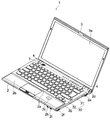
- FIG. 2 is a perspective view showing the PC 1 in an opened state.
- the main body 2 and the display 3 are connected to each other by a hinge 4 so as to be relatively rotatable.
- the display unit 3 includes a display screen 3 a in a region facing the main body unit 2 when the display unit 3 is closed with respect to the main body unit 2.
- the main unit 2 includes an input operation unit 2a such as a keyboard in a region facing the display unit 3 when the display unit 3 is closed with respect to the main unit 2, and a palm rest 2b for the user to put his wrist on during input operation. And a non-contact type IC (Integrated Circuit) card antenna 2c and a slide type switch unit 7 (switch device).
- the main body 2 further includes a power switch 2d, an external display output terminal 2e, a USB (Universal Serial Bus) connector 2f, a disk entrance / exit 2g of a disk drive (not shown), and a microphone on the side surface of the main body 2. It has an input terminal 2h and a headphone output terminal 2i.
- the configuration of the switch unit 7 will be described in detail later.
- the main body 2 further includes a housing 30 in which a top case 32 and a bottom case 31 are combined.
- the top case 32 is provided with the input operation unit 2a, the switch unit 7, and the like.
- the bottom case 31 includes a placement surface on which the PC 1 is placed on a desk or the like.
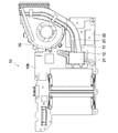
- the main body 2 further includes a motherboard 10, a cooling fan 20, and the like inside the housing 30.
- FIG. 3 is a plan view showing the mother board and the cooling fan from the lower surface side.
- FIG. 4 is a plan view showing the mother board and the cooling fan from the upper surface side.
- Electronic components such as a main memory, a CPU 12, an external graphics chip 13, a chip set 18, and other control circuits are mounted on the upper surface 10a and the lower surface 10b of the motherboard 10.
- the heat receiving plate 21 is provided in close contact with the upper surface of the CPU 12, and the heat receiving plate 22 is provided in close contact with the upper surface of the external graphics chip 13.
- a heat pipe 23 is thermally connected to the heat receiving plates 21 and 22, and the cooling fan 20 is thermally connected to the heat pipe 23.
- the cooling fan 20 cools heating elements such as the CPU 12 and the external graphics chip 13 mounted on the motherboard 10.
- the chip set 18 is a chip that manages the exchange of data with each device inside the PC 1.
- the chip set 18 includes a built-in graphics chip and the like.
- the chip set 18 has a connection interface with each peripheral device such as a nonvolatile memory or an EC (Embedded Controller).
- the external graphics chip 13 and the built-in graphics chip perform drawing processing based on the data output from the CPU 12, and output the generated video signal for display on the display screen 3a of the display unit 3.
- the built-in graphics chip is inferior in drawing processing capability to the external graphics chip 13, but the power consumption is low.
- the external graphics chip 13 has high processing capability in 3D processing, high-resolution rendering processing, and the like, but power consumption increases because it drives itself and peripheral devices, and the power load on the entire system of the PC 1 also increases. Therefore, when the external graphics chip 13 is used by connecting an external monitor or an AC (Alternating Current) adapter to the PC 1, for example, when driving a Blu-ray disc drive, when executing a 3D application, or when displaying a high resolution image Etc. are useful.
- the built-in graphics chip is useful when the remaining battery level is low, or when it is desired to reduce the number of rotations of the fan to reduce noise.
- the PC 1 includes devices necessary as a computer, such as an interface such as a battery, an HDD (Hard Disk Drive), and a terminal.
- an interface such as a battery, an HDD (Hard Disk Drive), and a terminal.
- HDD Hard Disk Drive
- the PC 1 performs a drawing process using a built-in graphics chip, a mode that performs a drawing process using the external graphics chip 13, and a mode that performs a drawing process using a graphics chip suitable for the current use situation after determining the use situation of the PC 1. Can be executed.
- the PC 1 switches between these three modes and executes any one mode. As a result, either the built-in graphics chip or the external graphics chip 13 performs the drawing process.
- the switching of the graphics chip for performing the drawing process can be performed, for example, by the EC as the control unit controlling the on / off state of the power supply to the external graphics chip 13 or the like.
- the EC acquires the detection result of the switch switching position detected by the switch module 300 (described later) of the switch unit 7. Based on the acquired detection result, the EC outputs a power on / off control signal for switching the power supply on / off state to the external graphics chip 13 to a power supply circuit (not shown).
- the power supply circuit switches on / off states of power supply to the external graphics chip 13 based on a power on / off control signal from the EC. Since power is supplied from the power supply circuit to the external graphics chip 13, the external graphics chip 13 can perform drawing processing. On the other hand, when power is not supplied from the power supply circuit to the external graphics chip 13, drawing processing is performed only on the internal graphics chip.
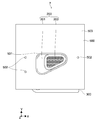
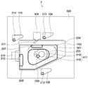
- FIG. 5 is a top view of the switch unit 7.
- the switch unit 7 is a slide type switch unit for allowing the user to select, for example, three modes of drawing processing.
- the drawing process mode can be switched by moving the operation unit 203 of the movable unit 200 exposed from the cover opening 501 of the cover 500 to a predetermined position in the cover opening 501.
- the operation unit 203 is directly movable between two positions of all combinations at positions corresponding to the three vertices of the rounded triangular cover opening 501.
- FIG. 6 is an exploded perspective view of the switch unit 7 and shows the switch unit 7 from the top case 32 side (cover 500 side).
- FIG. 7 is another exploded perspective view of the switch unit 7 and shows the switch unit 7 from the bottom case 31 (see FIG. 2) side.
- FIG. 8 is a bottom view of the switch unit 7.
- the surface facing the top case 32 when each member is arranged in the housing 30 is described as “upper surface”, and the surface facing the bottom case 31 is described as “lower surface”.
- the switch unit 7 includes a cover 500 (support unit), a guide unit 100 (support unit), a movable unit 200, a switch module 300 (detection unit), and a regulation unit 400. These members are combined in this order from the top case 32 side (cover 500 side) to the bottom case 31 side.
- the cover 500 protects the inside of the switch unit 7 and guides the movement of the movable unit 200.
- the cover 500 is made of, for example, a metal such as aluminum or a resin.
- the cover 500 is provided with a cover opening 501 penetrating between the upper surface 503 side and the lower surface 504 side.
- the cover opening 501 guides the operation unit 203 of the movable unit 200 so that it can move in the surface direction of the cover opening 501.
- the cover opening 501 has a rounded triangular shape.
- the cover 500 is provided with a boss hole 506 for screwing the switch module 300 to the cover 500 and a boss hole 507 for screwing the switch module 300 and the restricting portion 400 to the cover 500.
- three LED (Light Emitting Diode) openings 502 are provided so as to correspond to the three switching positions of the switch unit.
- a light guide system for guiding light from a plurality of light emitting sources such as LEDs provided in the main body 2 of the PC 1 to the respective LED openings 502 is provided below the cover 500. Then, in these three LED openings 502, light is exposed only from one LED opening 502 according to the switching position selected by the switch unit 7, that is, the drawing process mode, and is lit / flashed.
- the mode switching state can be presented to the user.
- a guide unit 100 is provided on the lower surface 504 side of the cover 500.
- the guide part 100 is for guiding the movement of the movable part 200 in cooperation with the cover opening 501.
- the guide unit 100 is made of, for example, a light guide resin.
- the guide part 100 is fixed to the lower surface of the cover 500. That is, on the upper surface 101 of the guide portion 100, three insertion portions 104 that are respectively inserted into the three LED openings 502 of the cover 500 are provided. By these insertion portions 104, the guide portion 100 is positioned at three points with respect to the cover 500, and the light guide to each LED opening 502 is achieved.
- the upper surface 101 of the guide unit 100 is attached to the lower surface 504 of the cover 500 with a double-sided tape.
- the guide portion 100 is provided with a guide opening 103 penetrating between the upper surface 101 side and the lower surface 102 side.
- the guide opening 103 guides the plate portion 201 (described later) of the movable portion 200 on the inner peripheral surface 111 so as to be movable in the surface direction of the guide opening 103.
- X axis two axes forming the opening surface of the guide opening 103 are described as “X axis” and “Y axis”.
- An axis orthogonal to the opening surface of the guide opening 103 is described as “Z axis”.
- a direction from the bottom case 31 side to the top case 32 side (cover 500 side) on the Z axis is described as “Z axis upward direction”.
- a direction from the top case 32 side (cover 500 side) to the bottom case 31 side on the Z axis is described as a “Z axis downward direction”.
- bosses 105 and 106 for positioning the switch module 300 and the restriction part 400 with respect to the guide part 100, and for screwing the switch module 300 and the restriction part 400 to the guide part 100 are screwed.
- a boss hole 107 is provided on the lower surface 102 of the guide part 100.
- Recesses 108, 109, and 110 are provided around the guide opening 103 on the lower surface 102 of the guide unit 100.
- the concave portions 108, 109, and 110 are engaged with upper convex portions 213, 214, and 215 (described later) of the movable portion 200 to guide the movement of the movable portion 200 on the XY plane.
- the recesses 108, 109, and 110 are all the same shape and the same size.
- the planar shape of the recesses 108, 109, and 110 on the XY plane is a rounded triangle that is substantially similar to the planar shape of the cover opening 501 on the XY plane. All of the recesses 108, 109, and 110 are provided in a positional relationship such that corresponding sides of each triangle are parallel to the cover opening 501 to which the guide portion 100 is fixed.
- the movable part 200 includes a plate part 201, an operation part 203, three extending parts 209, 210, 211, an engagement protrusion 205, a first pressing protrusion 207, and a second pressing protrusion 208. .
- the planar shape of the plate portion 201 on the XY plane is substantially similar to the planar shape of the guide opening 103 of the guide portion 100 on the XY plane.
- the plate part 201 is disposed in the guide opening 103.
- the outer peripheral surface 223 of the plate portion 201 is arranged in a positional relationship such that the corresponding surfaces face each other with respect to the inner peripheral surface 111 of the guide opening 103.
- the plate portion 201 can move in the guide opening 103 on the XY plane.
- the operation unit 203 is provided on the upper surface 202 of the plate unit 201 so as to protrude in the Z-axis direction.
- the planar shape of the operation unit 203 on the XY plane is substantially similar to the planar shape of the cover opening 501 on the XY plane.
- the operation unit 203 is provided on the plate unit 201 in a positional relationship that is equal to the positional relationship of the cover opening 501 with respect to the guide opening 103.
- the outer peripheral surface 221 of the operation portion 203 is in a positional relationship such that the corresponding surfaces face each other with respect to the inner peripheral surface 508 of the cover opening 501. Be placed.
- the operation unit 203 can move in the cover opening 501 on the XY plane.
- the movable portion 200 is a combination of all combinations 2 at positions where the operation portion 203 corresponds to the three vertices of the rounded triangular cover opening 501 by the inner peripheral surface 111 of the guide opening 103 and the inner peripheral surface 508 of the cover opening 501. It is supported so that it can move directly between positions.
- the position of the operation unit 203 at a position corresponding to any corner of the cover opening 501 having a rounded triangular shape is described as a “corner position”.
- the extended portions 209, 210, and 211 are provided at the end of the lower surface 204 of the plate portion 201 so as to protrude from the outer peripheral surface 223.
- semi-conical upper convex portions 212, 213, and 214 are provided so as to protrude in the Z-axis direction, respectively.
- the upper convex portions 212, 213, and 214 are engaged with the concave portions 108, 109, and 110 of the guide portion 100, respectively. Thereby, the movable part 200 is held by the guide part 100. Further, the movement of the upper convex portions 212, 213, 214 in the Z-axis upward direction is restricted by the bottom surfaces of the concave portions 108, 109, 110.
- Approximate hemispherical lower convex portions 215, 216, and 217 are provided on the lower surfaces of the distal ends of the extending portions 209, 210, and 211 so as to protrude in the Z-axis direction, respectively.
- a substantially hemispherical lower convex portion 218 is provided on the lower surface of the extending portion 209 so as to protrude in the Z-axis direction.
- a substantially hemispherical lower convex portion 219 is provided on the lower surface 204 of the plate portion 201 so as to protrude in the Z-axis direction.
- the tips of the lower convex portions 215 to 219 are located on the same XY plane.
- An engagement protrusion 205 is provided on the lower surface 204 of the plate portion 201.
- the engaging protrusion 205 is designed to be engageable with an engaging portion 403 (described later) of the restricting portion 400.
- the engagement protrusion 205 is provided at a position corresponding to the approximate center of the operation unit 203 and protrudes in the Z-axis direction.
- the engagement protrusion 205 is substantially cylindrical and has a substantially hemispherical tip 206.
- the engagement protrusion 205 moves along a triangular locus.
- the upper convex portions 212, 213, and 214 also move along an inner peripheral surface of the inner peripheral surface of the concave portions 108, 109, and 110 while drawing the same triangular locus as the locus of movement of the engaging protrusion 205.
- the first pressing protrusion 207 and the second pressing protrusion 208 are provided along the outer periphery of the lower surface 204 of the plate portion 201 and protrude in the Z-axis direction.
- the first pressing protrusion 207 and the second pressing protrusion 208 are designed to be able to press a first operation piece 311 and a second operation piece 312 (described later) of the switch module 300, respectively.
- the first pressing protrusion 207 and the second pressing protrusion 208 are provided at positions corresponding to predetermined two sides of the triangle of the operation unit 203 on the lower surface 204.
- a switch module 300 is provided below the guide portion 100 fixed to the cover 500.
- the switch module 300 includes a printed circuit board 315 on which a wiring pattern is formed, a motherboard connector 314, an LED board connector 313, a first switch element 309, and a second switch element 310.
- the printed circuit board 315 penetrates between the upper surface 301 side and the lower surface 302 side and is inserted into the positioning holes 303 and 304 and the boss holes 506, 507 and 107 respectively inserted into the bosses 105 and 106 of the guide part 100.
- Through holes 305, 306, 307 used for screwing are provided.
- the printed circuit board 315 is provided with an opening 308 penetrating between the upper surface 301 side and the lower surface 302 side.
- the first pressing protrusion 207, the second pressing protrusion 208, and the engaging protrusion 205 of the movable part 200 are always exposed from the opening 308, and the tips of the lower convex parts 215 to 219 of the movable part 200 are exposed.
- the switch module 300 is designed so that it can always contact the upper surface 301 of the switch module 300. When the tips of the lower convex portions 215 to 219 of the movable portion 200 abut on the upper surface 301, the movement of the movable portion 200 in the downward direction of the Z axis is restricted.
- the motherboard connector 314 is mounted on the lower surface 302 of the printed circuit board 315, and the LED substrate connector 313 is mounted on the upper surface 301 of the printed circuit board 315.
- a plurality of connection terminals as contact groups of the motherboard connector 314 and the LED board connector 313 are connected to the wiring pattern of the printed board 315, respectively.
- the motherboard connector 314 is connected to the motherboard 10 via a flexible flat cable (not shown).
- the LED board connector 313 is connected to an LED board (not shown) via a flexible flat cable (not shown). In this way, the switch module 300 also plays a role of relaying between the LED board and the motherboard 10.
- the first switch element 309 and the second switch element 310 are mounted in the vicinity of the opening 308 on the upper surface 301 of the printed board 315.
- the first switch element 309 and the second switch element 310 are provided at positions facing the first pressing protrusion 207 and the second pressing protrusion 208 of the movable part 200 in the XY axis directions, respectively.
- the first switch element 309 and the second switch element 310 are provided with a first operation piece 311 and a second operation piece 312, respectively.
- the first operation piece 311 and the second operation piece 312 are designed so that they can be pressed in the XY axis directions by the first pressing protrusion 207 and the second pressing protrusion 208, respectively.
- the first operation piece 311 and the second operation piece 312 are urged in a direction facing the first pressing protrusion 207 and the second pressing protrusion 208, respectively, and protrude on the XY plane.
- the first switch element 309 and the second switch element 310 can be switched to an on state.
- the first switch protrusion 207 of the movable part 200 presses the first operation piece 311 so that the first switch element 309 is switched on.
- the second switch element 310 When the second pressing projection 208 presses the second operation piece 312, the second switch element 310 is switched to the on state.
- Each of the first switch element 309 and the second switch element 310 outputs an on / off state to the EC through a flexible flat cable connected to the motherboard connector 314.
- FIG. 9 is a six-side view of the restriction unit 400.
- a restriction unit 400 is provided below the switch module 300.
- the restricting unit 400 includes, for example, a plate spring 401 as an urging unit and an engaging unit 403 provided on the plate spring 401.
- the leaf spring 401, the engaging portion 403, and the engaging protrusion 205 of the movable portion 200 constitute a positioning means for localizing the movable portion 200 that can move to a predetermined position.
- the leaf spring 401 is configured by using a thin metal such as stainless steel or a resin, for example.
- One end portion 412 of the leaf spring 401 passes through between the upper surface 402 side and the lower surface 404 side, and is screwed into a positioning hole 405 inserted into the boss 105 of the guide portion 100 and a boss hole 507 of the cover 500.
- a through-hole 406 used for the above.
- the other end portion 413 of the leaf spring 401 penetrates between the upper surface 402 side and the lower surface 404 side, and is inserted into the positioning hole 407 inserted into the boss 106 of the guide portion 100 and the boss hole 107 of the guide portion 100 with a screw.
- a through-hole 408 used to stop is provided.
- the leaf spring 401 is supported at both end portions 412 and 413 through these holes 405 to 408.
- the engaging portion 403 is made of resin, for example.
- the engaging portion 403 is fixed to a middle portion 419 between the both end portions 412 and 413 as support points so as to face the engaging protrusion 205 of the movable portion 200.
- the engaging portion 403 can move in the Z-axis direction by the biasing force of the leaf spring 401.
- the engaging portion 403 includes a base portion 416 and a bulging portion 417.
- the base 416 is installed on the leaf spring 401 and has a flat plate shape.
- the bulging portion 417 is provided on the upper surface of the base portion 416 so as to bulge in the Z-axis direction.
- the bulging portion 417 has a tapered surface 419 and a substantially flat top surface 418.
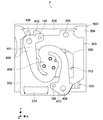
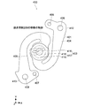
- FIG. 10 is a top view of the restricting portion 400, and is a view showing a movement locus of the engaging protrusion 205 of the movable portion 200.
- the engaging portion 403 is designed so that the engaging protrusion 205 is positioned corresponding to the tapered surface 419 when the operation portion 203 is at the three corner positions of the cover opening 501. Is done.
- the bulging portion 417 has an engaging projection 205 which is the top surface of the bulging portion 417 when the operation portion 203 moves directly from any one corner position to another corner position. Designed to move over 418.
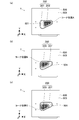
- FIG. 11 shows how the operation unit 203 is positioned at three corner positions of the cover opening 501. In the following description, these three corner positions are described as “corner positions A, B, and C”.
- FIG. 11A shows a state where the operation unit 203 is positioned at the corner position A.
- FIG. 11B shows a state where the operation unit 203 is positioned at the corner position B.
- FIG. 11C shows a state where the operation unit 203 is positioned at the corner position C.
- FIG. 12 is a schematic diagram illustrating operations of the movable unit 200 and the regulating unit 400.
- this schematic diagram is drawn after changing from an actual shape for easy understanding.
- the operation unit 203 is positioned at the corner position B.
- the tip 206 of the engaging protrusion 205 is pressed against the tapered surface 419 a (first tapered surface) of the bulging portion 417 of the engaging portion 403 of the restricting portion 400 by the urging force of the leaf spring 401.
- the movement of the movable portion 200 in the direction toward the bulging portion 417 is restricted. Is done. Further, the outer peripheral surface 221 of the operation portion 203 is brought into contact with the inner peripheral surface 508 of the cover opening 501 due to the interference between the tip 206 of the engaging projection 205 and the tapered surface 419a of the bulging portion 417 due to the urging force of the leaf spring 401. The outer peripheral surface 223 of the plate portion 201 is in contact with the inner peripheral surface 111 of the guide opening 103.
- the movement of the movable part 200 in the direction toward the inner peripheral surface 508 of the cover opening 501 with which the operation part 203 is in contact is restricted.
- the movement of the movable portion 200 in the direction toward the bulging portion 417 of the engagement protrusion 205 is restricted, and the movement in the direction toward the inner peripheral surface 508 of the cover opening 501 with which the operation portion 203 is in contact. Is restricted, the movement of the movable part 200 in the XY plane is restricted.
- the user feels resistance in the moving operation of the movable part 200.
- This resistance is abruptly reduced when the engaging protrusion 205 reaches the top surface 418 of the bulging portion 417, and the friction between the substantially hemispherical tip 206 of the engaging protrusion 205 and the top surface 418 of the bulging portion 417. Due to Such a change in resistance is given to the user as a click feeling.
- the engagement protrusion 205 passes through the top surface 418 of the bulging portion 417 and the opposite tapered surface 419b ( The position of interference with the second tapered surface is reached. Then, due to the urging force of the leaf spring 401, the engaging protrusion 205 is drawn along the tapered surface 419b, and as a result, the operating portion is moved to the corner position A. As a result, the engaging protrusion 205 is positioned at the corner position A. An operation in which the engagement protrusion 205 is guided by the biasing force and the taper action of the leaf spring 401 is given to the user as a feeling of pulling.
- FIG. 13 is a transparent top view schematically showing the switch unit 7 when the operation unit 203 is positioned at the corner position A.
- FIG. In the figure, for the sake of clarity, the illustration of the parts that are not necessary for the following description is omitted. The same applies to the following figures.
- the outer peripheral surface 221 of the operation unit 203 abuts on the inner peripheral surface of the cover opening 501 and the outer peripheral surface 223 of the plate unit 201 is guided. It is in contact with the inner peripheral surface 111 of the opening 103.
- the engagement protrusion 205 is located on the tapered surface 419.
- the upper convex portions 212, 213, and 214 are located at corner positions corresponding to the corner position A of the cover opening 501 in the concave portions 108, 109, and 110 of the guide portion 100.
- the engaging protrusion 205 passes through the top surface 418.
- the operation unit 203 moves along the inner peripheral surface of the cover opening 501
- the plate unit 201 moves along the inner peripheral surface 111 of the guide opening 103.
- the upper convex portions 212, 213, and 214 move along the inner peripheral surfaces of the concave portions 108, 109, and 110.
- the first pressing protrusion 207 and the second pressing protrusion 208 are in contact with the first operation piece 311 and the second operation piece 312 of the first switch element 309 and the second switch element 310, so that the first operation is performed.
- the first operation piece 311 and the second operation piece 312 are pressed against the urging force of the piece 311 and the second operation piece 312. As a result, the first switch element 309 and the second switch element 310 are turned on.
- FIG. 14 is a transparent top view schematically showing the switch unit 7 when the operation unit 203 is positioned at the corner position B.
- FIG. 14 In the movable part 200, when the operating part 203 reaches the corner position B, the engaging protrusion 205 also reaches the tapered surface 419.
- the upper convex portions 212, 213, and 214 are located at corner positions corresponding to the corner position B of the cover opening 501 in the concave portions 108, 109, and 110 of the guide portion 100.
- the first pressing protrusion 207 and the second pressing protrusion 208 further press the first operation piece 311 and the second operation piece 312 of the first switch element 309 and the second switch element 310.
- the engaging protrusion 205 passes through the top surface 418.
- the operation unit 203 moves along the inner peripheral surface of the cover opening 501
- the plate unit 201 moves along the inner peripheral surface 111 of the guide opening 103.
- the upper convex portions 212, 213, and 214 move along the inner peripheral surfaces of the concave portions 108, 109, and 110 of the guide portion 100.
- the first pressing protrusion 207 is separated from the first switch element 309 while the tip of the first operating piece 311 is in contact with the side surface of the first pressing protrusion 207 by the urging force of the first operating piece 311. Move in the direction.
- the second pressing projection 208 moves while maintaining the pressing state of the second operation piece 312.
- FIG. 15 is a transparent top view schematically showing the switch unit 7 when the operation unit 203 is positioned at the corner position C.
- FIG. 15 In the movable unit 200, when the operation unit 203 reaches the corner position C, the engagement protrusion 205 also reaches the tapered surface 419.
- the upper convex portions 212, 213, and 214 are located at corner positions corresponding to the corner position C of the cover opening 501 in the concave portions 108, 109, and 110 of the guide portion 100.
- the first pressing protrusion 207 is separated from the first operation piece 311. Accordingly, the first switch element 309 is switched to the off state.
- the second pressing protrusion 208 continues to press the second operation piece 312. Thereby, the ON state of the second switch element 310 is maintained.
- the engaging protrusion 205 passes through the top surface 418.
- the operation unit 203 moves along the inner peripheral surface of the cover opening 501
- the plate unit 201 moves along the inner peripheral surface 111 of the guide opening 103.
- the upper convex portions 212, 213, and 214 move along the inner peripheral surfaces of the concave portions 108, 109, and 110 of the guide portion 100.
- the second pressing protrusion 208 is separated from the second switch element 310 while the tip of the second operating piece 312 is in contact with the side surface of the second pressing protrusion 208 by the urging force of the second operating piece 312. Move in the direction.
- the operation unit 203 reaches the corner position A
- the second pressing protrusion 208 is separated from the second operation piece 312.
- the 2nd switch element 310 switches to an OFF state.
- the operation unit 203 when the operation unit 203 is at the corner position A, the first switch element 309 and the second switch element 310 are turned off, and when the operation unit 203 is at the corner position B, the first switch element 309 and the second switch element 309 are turned off.
- the switch element 310 is in the on state and is in the corner position C, the first switch element 309 is in the off state and the second switch element 310 is in the on state.
- Each of the first switch element 309 and the second switch element 310 outputs an on / off state to the EC.
- the operation of the switch unit 7 when the operation unit 203 moves counterclockwise from the corner position A has been described, but the operation of the switch unit 7 when the operation unit 203 moves clockwise from the corner position A. Is the same.
- the operation part 203 can be directly moved between two positions of all combinations of the corner positions A, B, and C.
- the three modes of a drawing process can be directly switched between all the modes.
- the on / off state of the first switch element 309 and the second switch element 310 is a combination of three types by pressing from the XY axis direction that is the moving direction of the movable unit 200. Since the switch module 300 that can be switched at is adopted, the switch mechanism can be simplified. Further, since the operation unit 200 is localized at the three corner positions by the localization means, the on / off states of the first switch element 309 and the second switch element 310 may be changed against the intention of the user. There is little, and reliability improves.
- the size of the entire switch may increase.
- the switch unit 7 of the present embodiment structurally realizes direct switching between the three modes, the switch unit 7 can be reduced in size by configuring each mechanical component small. Further, by covering the cover opening 501 from the inside with the plate part 201 of the movable part 200, the inside of the switch part 7 is not visually recognized from the outside, and the design is good.
- the structure of the switch unit 7 of this embodiment can be applied to various slide-type switch units.
- the movable part 200 is supported so as to be directly movable between two positions of all combinations of the three corner positions of the triangle of the cover opening 501 and is localized at the three corner positions.
- the movable part is positioned between two positions of all combinations in the polygonal corner position having four or more corners. Can be moved directly and can be localized at four or more corner positions. Thereby, malfunctioning of the switch part 7 can be prevented.
- the movement of the movable part 200 may be restricted by providing a restriction part 400 or the like between two adjacent positions of the slide type switch part in which the movable part can move at two or more positions on a straight line.
- a restriction part 400 or the like between two adjacent positions of the slide type switch part in which the movable part can move at two or more positions on a straight line.
- the operating force of the movable part 200 can be adjusted by adjusting the urging force of the leaf spring 401 of the restricting part 400. Further, by changing the shape of the bulging portion 417, the shape of the engagement protrusion 205 of the movable portion 200, the urging force of the leaf spring 401, or the like, a desired click feeling and pulling feeling can be given to the user.
- the switch unit 7 has been described as being used for switching the drawing process mode, but is not limited thereto, and can be used for switching various operation processes.
Landscapes
- Engineering & Computer Science (AREA)
- Theoretical Computer Science (AREA)
- General Engineering & Computer Science (AREA)
- Physics & Mathematics (AREA)
- General Physics & Mathematics (AREA)
- Computer Hardware Design (AREA)
- Human Computer Interaction (AREA)
- Computing Systems (AREA)
- Mathematical Physics (AREA)
- Switches With Compound Operations (AREA)
- Switch Cases, Indication, And Locking (AREA)
- Slide Switches (AREA)
- Input From Keyboards Or The Like (AREA)
Abstract
Description
スイッチ部は、可動部と、支持部と、検知部とを有する。
上記可動部は、利用者により操作されることが可能である。
上記支持部は、上記可動部を3以上の位置における全ての組み合わせの2位置間で直接移動自在に支持する。
上記検知部は、上記可動部が各々の上記位置に移動したことを検知する。
上記制御部は、上記検知部の検知結果を認識する。
可動部は、第2のテーパ面との干渉位置に達すると、付勢手段の付勢力によって第2のテーパ面に沿って引き込まれ、この結果、可動部の移動が促される。このような付勢手段の付勢力と第2のテーパ面のテーパ作用とにより可動部が誘導される動作が引き込み感として利用者に与えられる。
上記可動部は、利用者により操作されることが可能である。
上記支持部は、上記可動部を3以上の位置における全ての組み合わせの2位置間で直接移動自在に支持する。
上記検知部は、上記可動部が各々の上記位置に移動したことを検知する。
可動部は、第2のテーパ面との干渉位置に達すると、付勢手段の付勢力によって第2のテーパ面に沿って引き込まれ、この結果、可動部の移動が促される。このような付勢手段の付勢力と第2のテーパ面のテーパ作用とにより可動部が誘導される動作が引き込み感として利用者に与えられる。
図1は、本発明の一実施形態に係るPCの閉じた状態を示す斜視図である。
PC1は、本体部2と、表示部3とを有する。
本体部2と表示部3とは、ヒンジ4により相対的に回動可能に連結される。表示部3は、表示部3が本体部2に対して閉じたとき本体部2に対面する領域に、表示画面3aを有する。
マザーボード10の上面10a及び下面10bには、メインメモリ、CPU12、外部グラフィックスチップ13、チップセット18、その他の制御回路などの電子部品が実装されている。
次に、PC1の動作状態の一例について説明する。PC1は、内蔵グラフィックスチップにより描画処理を行うモード、外部グラフィックスチップ13により描画処理を行うモード、PC1の使用状況を判断して現在の使用状況に適したグラフィックスチップにより描画処理を行うモードを実行可能である。PC1は、これら3つのモードを切り替えて何れか1つのモードを実行する。これにより、内蔵グラフィックスチップ及び外部グラフィックスチップ13の何れか一方が描画処理を行うこととなる。
次に、スイッチ部7の構成について説明する。なお、本明細書でスイッチ部7と記述するときは、筐体30のトップケース32の一部を含むものとする。このスイッチ部7に含まれるトップケース32の一部を、「カバー500」と呼ぶこととする。
スイッチ部7は、例えば描画処理の3つのモードを利用者に選択させるためのスライド式のスイッチ部である。カバー500のカバー開口501から露出する可動部200の操作部203をカバー開口501内の所定位置に移動させることで、描画処理のモードを切り替えることができる。本実施形態では、操作部203は角丸三角形のカバー開口501の3つの頂点に相当する位置における全ての組み合わせの2位置間で直接移動可能である。
カバー500は、スイッチ部7の内部を保護するとともに、可動部200の移動をガイドするためのものである。
カバー500の下面504側には、ガイド部100が設けられる。ガイド部100は、カバー開口501と協働して可動部200の移動をガイドするためのものである。
可動部200は、板部201と、操作部203と、3つの延出部209、210、211と、係合突起205と、第1の押圧突起207と、第2の押圧突起208とを有する。
カバー500に固定されたガイド部100の下方にはスイッチモジュール300が設けられる。スイッチモジュール300は、配線パターンが形成されたプリント基板315と、マザーボードコネクタ314と、LED基板コネクタ313と、第1のスイッチ素子309と、第2のスイッチ素子310とを有する。
図9は、規制部400の6面図である。
スイッチモジュール300の下方には、規制部400が設けられる。規制部400は、例えば付勢手段としての板ばね401と、板ばね401に設けられた係合部403とを有する。この板ばね401と、係合部403と、可動部200の係合突起205とにより、移動可能な可動部200を所定位置に定位させるための定位手段が構成される。
図中3つの点線円で示すように、係合部403は、操作部203がカバー開口501の3つのコーナ位置にあるとき、係合突起205がテーパ面419に対応して位置するように設計される。また、図中点線三角形で示すように、膨出部417は、操作部203が任意の1つのコーナ位置から他のコーナ位置に直接移動するとき、係合突起205が膨出部417の頂面418上を移動するように設計される。
次に、以上のように構成されたスイッチ部7における、操作部203が三角形のカバー開口501の内周面508に沿って3つのコーナ位置間を移動するときの、可動部200及び規制部400の動作について説明する。
以下の説明において、この3つのコーナ位置を、「コーナ位置A、B、C」と記述する。図11(a)は、操作部203がコーナ位置Aに位置する様子を示す。図11(b)は、操作部203がコーナ位置Bに位置する様子を示す。図11(c)は、操作部203がコーナ位置Cに位置する様子を示す。
図12(a)に示すように、操作部203はコーナ位置Bに定位されている。このとき、係合突起205の先端206が板ばね401の付勢力により規制部400の係合部403の膨出部417のテーパ面419a(第1のテーパ面)に圧接している。板ばね401の付勢力による係合突起205の先端206と膨出部417のテーパ面419aとの干渉により、可動部200の、係合突起205が膨出部417に向かう方向への移動が規制される。また、板ばね401の付勢力による係合突起205の先端206と膨出部417のテーパ面419aとの干渉により、操作部203の外周面221がカバー開口501の内周面508に当接され、板部201の外周面223がガイド開口103の内周面111に当接されている。これにより、可動部200の、操作部203が当接しているカバー開口501の内周面508に向かう方向への移動が規制される。このように、可動部200の、係合突起205が膨出部417に向かう方向への移動が規制され、操作部203が当接しているカバー開口501の内周面508に向かう方向への移動が規制されることにより、可動部200のXY面内での移動が規制される。
次に、操作部203が三角形のカバー開口501の内周面508に沿って各1つのコーナ位置から他のコーナ位置へと移動するときの、スイッチ部7の動作について説明する。
図13は、操作部203がコーナ位置Aに位置するときのスイッチ部7を模式的に示す透過上面図である。
なお、同図においては、図をわかりやすくするため、以下の説明に直接必要ない部位については図示を省略している。以下の図についても同様である。
可動部200において、操作部203がコーナ位置Bに到達するとき、係合突起205もテーパ面419に到達する。上側凸部212、213、214は、ガイド部100の凹部108、109、110における、カバー開口501のコーナ位置Bに相当するコーナ位置に位置する。第1の押圧突起207及び第2の押圧突起208は、第1のスイッチ素子309及び第2のスイッチ素子310の第1の操作片311及び第2の操作片312をさらに押圧する。
可動部200において、操作部203がコーナ位置Cに到達するとき、係合突起205もテーパ面419に到達する。上側凸部212、213、214は、ガイド部100の凹部108、109、110における、カバー開口501のコーナ位置Cに相当するコーナ位置に位置する。第1の押圧突起207は、第1の操作片311から離間する。これにより、第1のスイッチ素子309がオフ状態に切り替わる。第2の押圧突起208は、第2の操作片312を引き続き押圧している。これにより、第2のスイッチ素子310のオン状態が維持される。
7…スイッチ部
100…ガイド部
103…ガイド開口
501…カバー開口
200…可動部
201…板部
203…操作部
205…係合突起(定位手段)
300…スイッチモジュール(検知部)
400…規制部
401…板ばね(定位手段)
403…係合部(定位手段)
417…膨出部
418…頂面
419…テーパ面
419a…第1のテーパ面
419b…第2のテーパ面
500…カバー
Claims (9)
- 利用者により操作されることが可能な可動部と、前記可動部を3以上の位置における全ての組み合わせの2位置間で直接移動自在に支持する支持部と、前記可動部が各々の前記位置に移動したことを検知する検知部とを有するスイッチ部と、
前記検知部の検知結果を認識する制御部と
を具備する情報処理装置。 - 請求項1に記載の情報処理装置であって、
前記スイッチ部は、前記可動部を各々の前記位置で定位させる定位手段をさらに有する
情報処理装置。 - 請求項2に記載の情報処理装置であって、
前記スイッチ部は、各々の前記2位置間に設けられ、前記可動部が各々の前記2位置間を移動する過程で、前記可動部とそれぞれ異なるタイミングで干渉して、前記可動部の前記移動を規制する第1のテーパ面及び前記可動部の移動を促す第2のテーパ面を有する係合部をさらに有する
情報処理装置。 - 請求項3に記載の情報処理装置であって、
前記スイッチ部は、前記係合部の前記各テーパ面と前記可動部とを圧接させるように付勢する付勢手段をさらに有する
情報処理装置。 - 請求項4に記載の情報処理装置であって、
前記制御部は、前記検知結果に基いて前記情報処理装置の動作処理を切り替える
情報処理装置。 - 利用者により操作されることが可能な可動部と、
前記可動部を3以上の位置における全ての組み合わせの2位置間で直接移動自在に支持する支持部と、
前記可動部が各々の前記位置に移動したことを検知する検知部と
を具備するスイッチ装置。 - 請求項6に記載のスイッチ装置であって、
前記可動部を各々の前記位置で定位させる定位手段
をさらに具備するスイッチ装置。 - 請求項7に記載のスイッチ装置であって、
各々の前記2位置間に設けられ、前記可動部が各々の前記2位置間を移動する過程で、前記可動部とそれぞれ異なるタイミングで干渉して、前記可動部の前記移動を規制する第1のテーパ面及び前記可動部の移動を促す第2のテーパ面を有する係合部
をさらに具備するスイッチ装置。 - 請求項8に記載のスイッチ装置であって、
前記係合部の前記各テーパ面と前記可動部とを圧接させるように付勢する付勢手段
をさらに具備するスイッチ装置。
Priority Applications (4)
| Application Number | Priority Date | Filing Date | Title |
|---|---|---|---|
| CN201080007357.2A CN102318024B (zh) | 2009-12-24 | 2010-12-17 | 信息处理装置和切换装置 |
| BRPI1007759A BRPI1007759A2 (pt) | 2009-12-24 | 2010-12-17 | aparelho de processamento de informação, e, dispositivo de comutação |
| RU2011133356/07A RU2011133356A (ru) | 2009-12-24 | 2010-12-17 | Устройство обработки информации и устройство переключателя |
| US13/146,674 US8530769B2 (en) | 2009-12-24 | 2010-12-17 | Information processing apparatus and switch device |
Applications Claiming Priority (2)
| Application Number | Priority Date | Filing Date | Title |
|---|---|---|---|
| JP2009293397A JP5446844B2 (ja) | 2009-12-24 | 2009-12-24 | 情報処理装置及びスイッチ装置 |
| JP2009-293397 | 2009-12-24 |
Publications (1)
| Publication Number | Publication Date |
|---|---|
| WO2011077677A1 true WO2011077677A1 (ja) | 2011-06-30 |
Family
ID=44195231
Family Applications (1)
| Application Number | Title | Priority Date | Filing Date |
|---|---|---|---|
| PCT/JP2010/007316 Ceased WO2011077677A1 (ja) | 2009-12-24 | 2010-12-17 | 情報処理装置及びスイッチ装置 |
Country Status (8)
| Country | Link |
|---|---|
| US (1) | US8530769B2 (ja) |
| JP (1) | JP5446844B2 (ja) |
| KR (1) | KR20120101613A (ja) |
| CN (1) | CN102318024B (ja) |
| BR (1) | BRPI1007759A2 (ja) |
| RU (1) | RU2011133356A (ja) |
| TW (1) | TW201140294A (ja) |
| WO (1) | WO2011077677A1 (ja) |
Families Citing this family (1)
| Publication number | Priority date | Publication date | Assignee | Title |
|---|---|---|---|---|
| JP2011141707A (ja) * | 2010-01-07 | 2011-07-21 | Sony Corp | 情報処理装置、情報処理方法及びプログラム |
Citations (5)
| Publication number | Priority date | Publication date | Assignee | Title |
|---|---|---|---|---|
| JPS6380735U (ja) * | 1986-11-13 | 1988-05-27 | ||
| JPH0410940U (ja) * | 1990-05-14 | 1992-01-29 | ||
| JPH0877882A (ja) * | 1994-09-02 | 1996-03-22 | Aiwa Co Ltd | スライド操作装置 |
| JP2002075132A (ja) * | 2000-08-29 | 2002-03-15 | Toyo Denso Co Ltd | パワーウィンドウ制御用操作部 |
| JP2008502103A (ja) * | 2004-06-02 | 2008-01-24 | イスカーリミテッド | 多機能キー・アセンブリ |
Family Cites Families (13)
| Publication number | Priority date | Publication date | Assignee | Title |
|---|---|---|---|---|
| JPS6334183Y2 (ja) * | 1979-12-25 | 1988-09-12 | ||
| JPS58328U (ja) * | 1981-05-26 | 1983-01-05 | 株式会社東海理化電機製作所 | 多方向スイツチ |
| JPS6380735A (ja) | 1986-09-25 | 1988-04-11 | Ishikawajima Harima Heavy Ind Co Ltd | 発電装置 |
| JP2783647B2 (ja) | 1990-04-27 | 1998-08-06 | キヤノン株式会社 | 液体噴射方法および該方法を用いた記録装置 |
| US5327162A (en) * | 1992-03-17 | 1994-07-05 | Alps Electric Co., Ltd. | X-y direction input device |
| JP3593700B2 (ja) | 1992-06-19 | 2004-11-24 | ソニー株式会社 | スライドスイッチ |
| US6834238B1 (en) * | 1998-06-08 | 2004-12-21 | Cytoscan Sciences Llc | Method for identifying optical contrast enhancing agents |
| US6689967B2 (en) * | 2002-03-11 | 2004-02-10 | Mitsuku Denshi Kogyo K.K. | Slide switch |
| JP4089397B2 (ja) * | 2002-11-20 | 2008-05-28 | 松下電器産業株式会社 | 多方向スライドスイッチ |
| JP4674167B2 (ja) * | 2006-01-25 | 2011-04-20 | ホシデン株式会社 | スライド操作式スイッチ |
| CN200956324Y (zh) * | 2006-10-18 | 2007-10-03 | 朱成辉 | 拨动开关 |
| JP2009134950A (ja) * | 2007-11-29 | 2009-06-18 | Mitsumi Electric Co Ltd | プッシュスイッチ付きスライドスイッチ |
| DE202008002002U1 (de) * | 2008-02-14 | 2008-04-10 | Trw Automotive Electronics & Components Gmbh | Redundanter Schalter |
-
2009
- 2009-12-24 JP JP2009293397A patent/JP5446844B2/ja not_active Expired - Fee Related
-
2010
- 2010-12-10 TW TW099143245A patent/TW201140294A/zh unknown
- 2010-12-17 US US13/146,674 patent/US8530769B2/en not_active Expired - Fee Related
- 2010-12-17 WO PCT/JP2010/007316 patent/WO2011077677A1/ja not_active Ceased
- 2010-12-17 CN CN201080007357.2A patent/CN102318024B/zh not_active Expired - Fee Related
- 2010-12-17 RU RU2011133356/07A patent/RU2011133356A/ru not_active Application Discontinuation
- 2010-12-17 KR KR1020117018083A patent/KR20120101613A/ko not_active Withdrawn
- 2010-12-17 BR BRPI1007759A patent/BRPI1007759A2/pt not_active IP Right Cessation
Patent Citations (5)
| Publication number | Priority date | Publication date | Assignee | Title |
|---|---|---|---|---|
| JPS6380735U (ja) * | 1986-11-13 | 1988-05-27 | ||
| JPH0410940U (ja) * | 1990-05-14 | 1992-01-29 | ||
| JPH0877882A (ja) * | 1994-09-02 | 1996-03-22 | Aiwa Co Ltd | スライド操作装置 |
| JP2002075132A (ja) * | 2000-08-29 | 2002-03-15 | Toyo Denso Co Ltd | パワーウィンドウ制御用操作部 |
| JP2008502103A (ja) * | 2004-06-02 | 2008-01-24 | イスカーリミテッド | 多機能キー・アセンブリ |
Also Published As
| Publication number | Publication date |
|---|---|
| CN102318024B (zh) | 2014-11-12 |
| KR20120101613A (ko) | 2012-09-14 |
| US8530769B2 (en) | 2013-09-10 |
| TW201140294A (en) | 2011-11-16 |
| CN102318024A (zh) | 2012-01-11 |
| JP2011134608A (ja) | 2011-07-07 |
| JP5446844B2 (ja) | 2014-03-19 |
| BRPI1007759A2 (pt) | 2016-02-23 |
| US20110279957A1 (en) | 2011-11-17 |
| RU2011133356A (ru) | 2013-02-20 |
Similar Documents
| Publication | Publication Date | Title |
|---|---|---|
| US9104374B2 (en) | Electronic device | |
| US10656673B1 (en) | Keyboard device | |
| US8102081B2 (en) | Electronic apparatus | |
| US8144450B2 (en) | Electronic apparatus | |
| EP3021199B1 (en) | Membrane switch leather case keyboard | |
| JP5181844B2 (ja) | キーボード、電子機器、キーボードの製造方法、電子機器の製造方法及びキーボード部品 | |
| US20080170038A1 (en) | Shape-changeable mouse | |
| US8570759B2 (en) | Controller and portable electronic apparatus | |
| EP2889734B1 (en) | Coordinate input device | |
| JP5446844B2 (ja) | 情報処理装置及びスイッチ装置 | |
| US8941991B2 (en) | Keyboard and electronic device employing the keyboard | |
| US20130331041A1 (en) | Electronic apparatus and control method for electronic apparatus | |
| JP2010287194A (ja) | マウス装置 | |
| JP2015049800A (ja) | キーボード装置 | |
| HK1165088A (en) | Information processing apparatus and switching device | |
| JP5195035B2 (ja) | スイッチ構造及びこれを備えた電子機器 | |
| US20250370555A1 (en) | Removable mouse module and electronic device including the same | |
| US8102370B2 (en) | Mode-changeable slim mouse | |
| WO2024242703A1 (en) | Notebook computer and power control method | |
| HK1146755A (en) | Controller and portable electronic apparatus | |
| CN102023710A (zh) | 键盘 | |
| HK1201094A1 (en) | Pointing device for interacting with touch-sensitive devices and method thereof | |
| TW201626170A (zh) | 鍵盤模組 |
Legal Events
| Date | Code | Title | Description |
|---|---|---|---|
| WWE | Wipo information: entry into national phase |
Ref document number: 201080007357.2 Country of ref document: CN |
|
| WWE | Wipo information: entry into national phase |
Ref document number: 13146674 Country of ref document: US |
|
| ENP | Entry into the national phase |
Ref document number: 20117018083 Country of ref document: KR Kind code of ref document: A |
|
| WWE | Wipo information: entry into national phase |
Ref document number: 2011133356 Country of ref document: RU |
|
| WWE | Wipo information: entry into national phase |
Ref document number: 6079/DELNP/2011 Country of ref document: IN |
|
| 121 | Ep: the epo has been informed by wipo that ep was designated in this application |
Ref document number: 10838917 Country of ref document: EP Kind code of ref document: A1 |
|
| NENP | Non-entry into the national phase |
Ref country code: DE |
|
| REG | Reference to national code |
Ref country code: BR Ref legal event code: B01A Ref document number: PI1007759 Country of ref document: BR |
|
| 122 | Ep: pct application non-entry in european phase |
Ref document number: 10838917 Country of ref document: EP Kind code of ref document: A1 |
|
| ENP | Entry into the national phase |
Ref document number: PI1007759 Country of ref document: BR Kind code of ref document: A2 Effective date: 20110809 |