US8530769B2 - Information processing apparatus and switch device - Google Patents
Information processing apparatus and switch device Download PDFInfo
- Publication number
- US8530769B2 US8530769B2 US13/146,674 US201013146674A US8530769B2 US 8530769 B2 US8530769 B2 US 8530769B2 US 201013146674 A US201013146674 A US 201013146674A US 8530769 B2 US8530769 B2 US 8530769B2
- Authority
- US
- United States
- Prior art keywords
- movable portion
- positions
- movable
- switch unit
- tapered surface
- Prior art date
- Legal status (The legal status is an assumption and is not a legal conclusion. Google has not performed a legal analysis and makes no representation as to the accuracy of the status listed.)
- Expired - Fee Related, expires
Links
Images




Classifications
-
- H—ELECTRICITY
- H01—ELECTRIC ELEMENTS
- H01H—ELECTRIC SWITCHES; RELAYS; SELECTORS; EMERGENCY PROTECTIVE DEVICES
- H01H25/00—Switches with compound movement of handle or other operating part
-
- H—ELECTRICITY
- H01—ELECTRIC ELEMENTS
- H01H—ELECTRIC SWITCHES; RELAYS; SELECTORS; EMERGENCY PROTECTIVE DEVICES
- H01H25/00—Switches with compound movement of handle or other operating part
- H01H25/002—Switches with compound movement of handle or other operating part having an operating member rectilinearly slidable in different directions
-
- G—PHYSICS
- G06—COMPUTING OR CALCULATING; COUNTING
- G06F—ELECTRIC DIGITAL DATA PROCESSING
- G06F1/00—Details not covered by groups G06F3/00 - G06F13/00 and G06F21/00
- G06F1/16—Constructional details or arrangements
-
- G—PHYSICS
- G06—COMPUTING OR CALCULATING; COUNTING
- G06F—ELECTRIC DIGITAL DATA PROCESSING
- G06F1/00—Details not covered by groups G06F3/00 - G06F13/00 and G06F21/00
- G06F1/16—Constructional details or arrangements
- G06F1/1601—Constructional details related to the housing of computer displays, e.g. of CRT monitors, of flat displays
-
- G—PHYSICS
- G06—COMPUTING OR CALCULATING; COUNTING
- G06F—ELECTRIC DIGITAL DATA PROCESSING
- G06F1/00—Details not covered by groups G06F3/00 - G06F13/00 and G06F21/00
- G06F1/16—Constructional details or arrangements
- G06F1/1613—Constructional details or arrangements for portable computers
-
- G—PHYSICS
- G06—COMPUTING OR CALCULATING; COUNTING
- G06F—ELECTRIC DIGITAL DATA PROCESSING
- G06F1/00—Details not covered by groups G06F3/00 - G06F13/00 and G06F21/00
- G06F1/16—Constructional details or arrangements
- G06F1/1613—Constructional details or arrangements for portable computers
- G06F1/1615—Constructional details or arrangements for portable computers with several enclosures having relative motions, each enclosure supporting at least one I/O or computing function
- G06F1/1616—Constructional details or arrangements for portable computers with several enclosures having relative motions, each enclosure supporting at least one I/O or computing function with folding flat displays, e.g. laptop computers or notebooks having a clamshell configuration, with body parts pivoting to an open position around an axis parallel to the plane they define in closed position
-
- G—PHYSICS
- G06—COMPUTING OR CALCULATING; COUNTING
- G06F—ELECTRIC DIGITAL DATA PROCESSING
- G06F1/00—Details not covered by groups G06F3/00 - G06F13/00 and G06F21/00
- G06F1/26—Power supply means, e.g. regulation thereof
-
- G—PHYSICS
- G06—COMPUTING OR CALCULATING; COUNTING
- G06F—ELECTRIC DIGITAL DATA PROCESSING
- G06F1/00—Details not covered by groups G06F3/00 - G06F13/00 and G06F21/00
- G06F1/26—Power supply means, e.g. regulation thereof
- G06F1/32—Means for saving power
- G06F1/3203—Power management, i.e. event-based initiation of a power-saving mode
-
- G—PHYSICS
- G06—COMPUTING OR CALCULATING; COUNTING
- G06F—ELECTRIC DIGITAL DATA PROCESSING
- G06F1/00—Details not covered by groups G06F3/00 - G06F13/00 and G06F21/00
- G06F1/26—Power supply means, e.g. regulation thereof
- G06F1/32—Means for saving power
- G06F1/3203—Power management, i.e. event-based initiation of a power-saving mode
- G06F1/3234—Power saving characterised by the action undertaken
- G06F1/3287—Power saving characterised by the action undertaken by switching off individual functional units in the computer system
-
- G—PHYSICS
- G06—COMPUTING OR CALCULATING; COUNTING
- G06F—ELECTRIC DIGITAL DATA PROCESSING
- G06F1/00—Details not covered by groups G06F3/00 - G06F13/00 and G06F21/00
- G06F1/26—Power supply means, e.g. regulation thereof
- G06F1/32—Means for saving power
- G06F1/3203—Power management, i.e. event-based initiation of a power-saving mode
- G06F1/3234—Power saving characterised by the action undertaken
- G06F1/3293—Power saving characterised by the action undertaken by switching to a less power-consuming processor, e.g. sub-CPU
-
- H—ELECTRICITY
- H01—ELECTRIC ELEMENTS
- H01H—ELECTRIC SWITCHES; RELAYS; SELECTORS; EMERGENCY PROTECTIVE DEVICES
- H01H25/00—Switches with compound movement of handle or other operating part
- H01H25/006—Switches with compound movement of handle or other operating part having an operating member slidable in a plane in one direction and pivotable around an axis located in the sliding plane perpendicular to the sliding direction
-
- H—ELECTRICITY
- H01—ELECTRIC ELEMENTS
- H01H—ELECTRIC SWITCHES; RELAYS; SELECTORS; EMERGENCY PROTECTIVE DEVICES
- H01H9/00—Details of switching devices, not covered by groups H01H1/00 - H01H7/00
- H01H9/16—Indicators for switching condition, e.g. "on" or "off"
- H01H9/161—Indicators for switching condition, e.g. "on" or "off" comprising light emitting elements
-
- H—ELECTRICITY
- H01—ELECTRIC ELEMENTS
- H01H—ELECTRIC SWITCHES; RELAYS; SELECTORS; EMERGENCY PROTECTIVE DEVICES
- H01H15/00—Switches having rectilinearly-movable operating part or parts adapted for actuation in opposite directions, e.g. slide switch
- H01H15/02—Details
- H01H15/025—Light-emitting indicators
-
- H—ELECTRICITY
- H01—ELECTRIC ELEMENTS
- H01H—ELECTRIC SWITCHES; RELAYS; SELECTORS; EMERGENCY PROTECTIVE DEVICES
- H01H15/00—Switches having rectilinearly-movable operating part or parts adapted for actuation in opposite directions, e.g. slide switch
- H01H15/02—Details
- H01H15/06—Movable parts; Contacts mounted thereon
- H01H15/10—Operating parts
- H01H15/102—Operating parts comprising cam devices
- H01H15/107—Operating parts comprising cam devices actuating conventional selfcontained microswitches
-
- Y—GENERAL TAGGING OF NEW TECHNOLOGICAL DEVELOPMENTS; GENERAL TAGGING OF CROSS-SECTIONAL TECHNOLOGIES SPANNING OVER SEVERAL SECTIONS OF THE IPC; TECHNICAL SUBJECTS COVERED BY FORMER USPC CROSS-REFERENCE ART COLLECTIONS [XRACs] AND DIGESTS
- Y02—TECHNOLOGIES OR APPLICATIONS FOR MITIGATION OR ADAPTATION AGAINST CLIMATE CHANGE
- Y02D—CLIMATE CHANGE MITIGATION TECHNOLOGIES IN INFORMATION AND COMMUNICATION TECHNOLOGIES [ICT], I.E. INFORMATION AND COMMUNICATION TECHNOLOGIES AIMING AT THE REDUCTION OF THEIR OWN ENERGY USE
- Y02D10/00—Energy efficient computing, e.g. low power processors, power management or thermal management
Definitions
- the movable portion presses down the first tapered surface against the bias force of the biasing means. Therefore, in this period of time, the user senses a feeling of resistance in the movement operation of the movable portion.
- the feeling of resistance suddenly decreases in a state where the movable portion leaves the first tapered surface. Such a change of the feeling of resistance is given to the user as a click feeling.
- FIG. 4 A plan view showing the motherboard and the cooling fan from an upper surface side.
- Z axis an axis orthogonal to the opening surface of the guide opening 103
- Z-axis up direction a direction on the Z axis from the bottom case 31 side to the top case 32 side (cover 500 side)
- Z-axis down direction a direction on the Z axis from the top case 32 side (cover 500 side) to the bottom case 31 side.
- the planar shape of the plate portion 201 on the XY surface is approximately similar to the planar shape of the guide opening 103 of the guide portion 100 on the XY surface.
- the plate portion 201 is arranged in the guide opening 103 .
- an outer periphery 223 of the plate portion 201 is arranged in a position relation with respect to the inner periphery 111 of the guide opening 103 in which corresponding surfaces of them face each other.
- the outer periphery 223 is guided by the inner periphery 111 of the guide opening 103 , whereby the plate portion 201 is movable in the guide opening 103 on the XY surface.
- lower convex portions 215 , 216 , 217 having approximate hemisphere shapes are provided so as to protrude in the Z axis direction, respectively.
- a lower convex portion 218 having an approximate hemisphere shape is provided so as to protrude in the Z axis direction.
- a lower convex portion 219 having an approximate hemisphere shape is provided so as to protrude in the Z axis direction. Tips of the lower convex portions 215 - 219 are positioned on the same XY surface.
- the plate spring 401 is structured by using, for example, a thin metal such as stainless or the like, resin, or the like. On one end portion 412 of the plate spring 401 , a position-keeping hole 405 into which the boss 105 of the guide portion 100 is inserted and a penetrating hole 406 used for securing to the boss hole 507 of the cover 500 by a screw, which penetrate between an upper surface 402 side and a the lower surface 404 side, are provided.
- FIG. 11( a ) shows that the operation portion 203 is located in the corner position A.
- FIG. 11( b ) shows that the operation portion 203 is located in the corner position B.
- FIG. 11( c ) shows that the operation portion 203 is located in the corner position C.
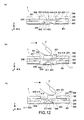
- a user (shown by U in the drawings) applies pressure in the X axis direction in order to move the operation portion 203 of the movable portion 200 kept in the corner position B in the X axis direction.
- the movable portion 200 starts to move in the X axis direction.
- the engage projection 205 presses down the bulge portion 417 against the bias force of the plate spring 401 .
- the engage projection 205 when the user continuously moves the operation portion 203 in the X axis direction, the engage projection 205 reaches, via the top surface 418 of the bulge portion 417 , an interference position with an opposite-side tapered surface 419 b (second tapered surface). Then, because of the bias force of the plate spring 401 , the engage projection 205 is pulled-in along the tapered surface 419 b , and as a result, the operation portion is moved to the corner position A. Because of this, the engage projection 205 is kept in the corner position A. Because of such a bias force of the plate spring 401 and taper effects, the operation of leading the engage projection 205 is supplied to the user as a pull-in feeling.
- FIG. 15 is a transparent top view schematically showing the switch unit 7 when the operation portion 203 is located in the corner position C.
- the first switch device 309 and the second switch device 310 are in the OFF states
- the first switch device 309 and the second switch device 310 are in the ON states
- the first switch device 309 is in the OFF state and the second switch device 310 is in the ON state.
- the first switch device 309 and the second switch device 310 output the ON/OFF states to the EC, respectively.
- the switch unit 7 when the operation portion 203 moves anticlockwise from the corner position A has been described, the same applies to the operation of the switch unit 7 when the operation portion 203 moves clockwise from the corner position A.
- the switch unit 7 of this embodiment it is possible to directly move the operation portion 203 between the two positions of all the combinations of the corner positions A, B, C.
- the switch unit 7 of this embodiment it is possible to directly switch the three modes of drawing processing among all the modes.
- the switch unit 7 is used to switch modes of drawing processing, not limited to this, it can be used to switch various operation processing.
Landscapes
- Engineering & Computer Science (AREA)
- Theoretical Computer Science (AREA)
- General Engineering & Computer Science (AREA)
- Physics & Mathematics (AREA)
- General Physics & Mathematics (AREA)
- Computer Hardware Design (AREA)
- Human Computer Interaction (AREA)
- Computing Systems (AREA)
- Mathematical Physics (AREA)
- Switches With Compound Operations (AREA)
- Switch Cases, Indication, And Locking (AREA)
- Slide Switches (AREA)
- Input From Keyboards Or The Like (AREA)
Applications Claiming Priority (3)
| Application Number | Priority Date | Filing Date | Title |
|---|---|---|---|
| JP2009293397A JP5446844B2 (ja) | 2009-12-24 | 2009-12-24 | 情報処理装置及びスイッチ装置 |
| JP2009-293397 | 2009-12-24 | ||
| PCT/JP2010/007316 WO2011077677A1 (ja) | 2009-12-24 | 2010-12-17 | 情報処理装置及びスイッチ装置 |
Publications (2)
| Publication Number | Publication Date |
|---|---|
| US20110279957A1 US20110279957A1 (en) | 2011-11-17 |
| US8530769B2 true US8530769B2 (en) | 2013-09-10 |
Family
ID=44195231
Family Applications (1)
| Application Number | Title | Priority Date | Filing Date |
|---|---|---|---|
| US13/146,674 Expired - Fee Related US8530769B2 (en) | 2009-12-24 | 2010-12-17 | Information processing apparatus and switch device |
Country Status (8)
| Country | Link |
|---|---|
| US (1) | US8530769B2 (ja) |
| JP (1) | JP5446844B2 (ja) |
| KR (1) | KR20120101613A (ja) |
| CN (1) | CN102318024B (ja) |
| BR (1) | BRPI1007759A2 (ja) |
| RU (1) | RU2011133356A (ja) |
| TW (1) | TW201140294A (ja) |
| WO (1) | WO2011077677A1 (ja) |
Families Citing this family (1)
| Publication number | Priority date | Publication date | Assignee | Title |
|---|---|---|---|---|
| JP2011141707A (ja) * | 2010-01-07 | 2011-07-21 | Sony Corp | 情報処理装置、情報処理方法及びプログラム |
Citations (13)
| Publication number | Priority date | Publication date | Assignee | Title |
|---|---|---|---|---|
| US4361739A (en) * | 1979-12-25 | 1982-11-30 | Kabushiki Kaisha Tokai Rika Denki Seisakusho | Two-directional switch |
| US4475015A (en) * | 1981-05-26 | 1984-10-02 | Kabushiki Kaisha Tokai Rika Denki Seisakusho | Multiposition switch |
| JPS6380735A (ja) | 1986-09-25 | 1988-04-11 | Ishikawajima Harima Heavy Ind Co Ltd | 発電装置 |
| JPH0410940A (ja) | 1990-04-27 | 1992-01-16 | Canon Inc | 液体噴射方法および該方法を用いた記録装置 |
| JPH065156A (ja) | 1992-06-19 | 1994-01-14 | Sony Corp | スライドスイッチ |
| US5327162A (en) * | 1992-03-17 | 1994-07-05 | Alps Electric Co., Ltd. | X-y direction input device |
| JPH0877882A (ja) | 1994-09-02 | 1996-03-22 | Aiwa Co Ltd | スライド操作装置 |
| JP2002075132A (ja) | 2000-08-29 | 2002-03-15 | Toyo Denso Co Ltd | パワーウィンドウ制御用操作部 |
| US6689967B2 (en) * | 2002-03-11 | 2004-02-10 | Mitsuku Denshi Kogyo K.K. | Slide switch |
| US6834238B1 (en) * | 1998-06-08 | 2004-12-21 | Cytoscan Sciences Llc | Method for identifying optical contrast enhancing agents |
| US6906269B2 (en) * | 2002-11-20 | 2005-06-14 | Matsushita Electric Industrial Co., Ltd. | Multi-directional slide switch |
| US20050269190A1 (en) | 2004-06-02 | 2005-12-08 | Iscar, Ltd. | Multifunction key assembly |
| US7294795B1 (en) * | 2006-01-25 | 2007-11-13 | Hosiden Corporation | Slide switch |
Family Cites Families (5)
| Publication number | Priority date | Publication date | Assignee | Title |
|---|---|---|---|---|
| JPH0346442Y2 (ja) * | 1986-11-13 | 1991-10-01 | ||
| JPH0410940U (ja) * | 1990-05-14 | 1992-01-29 | ||
| CN200956324Y (zh) * | 2006-10-18 | 2007-10-03 | 朱成辉 | 拨动开关 |
| JP2009134950A (ja) * | 2007-11-29 | 2009-06-18 | Mitsumi Electric Co Ltd | プッシュスイッチ付きスライドスイッチ |
| DE202008002002U1 (de) * | 2008-02-14 | 2008-04-10 | Trw Automotive Electronics & Components Gmbh | Redundanter Schalter |
-
2009
- 2009-12-24 JP JP2009293397A patent/JP5446844B2/ja not_active Expired - Fee Related
-
2010
- 2010-12-10 TW TW099143245A patent/TW201140294A/zh unknown
- 2010-12-17 US US13/146,674 patent/US8530769B2/en not_active Expired - Fee Related
- 2010-12-17 WO PCT/JP2010/007316 patent/WO2011077677A1/ja not_active Ceased
- 2010-12-17 CN CN201080007357.2A patent/CN102318024B/zh not_active Expired - Fee Related
- 2010-12-17 RU RU2011133356/07A patent/RU2011133356A/ru not_active Application Discontinuation
- 2010-12-17 KR KR1020117018083A patent/KR20120101613A/ko not_active Withdrawn
- 2010-12-17 BR BRPI1007759A patent/BRPI1007759A2/pt not_active IP Right Cessation
Patent Citations (14)
| Publication number | Priority date | Publication date | Assignee | Title |
|---|---|---|---|---|
| US4361739A (en) * | 1979-12-25 | 1982-11-30 | Kabushiki Kaisha Tokai Rika Denki Seisakusho | Two-directional switch |
| US4475015A (en) * | 1981-05-26 | 1984-10-02 | Kabushiki Kaisha Tokai Rika Denki Seisakusho | Multiposition switch |
| JPS6380735A (ja) | 1986-09-25 | 1988-04-11 | Ishikawajima Harima Heavy Ind Co Ltd | 発電装置 |
| JPH0410940A (ja) | 1990-04-27 | 1992-01-16 | Canon Inc | 液体噴射方法および該方法を用いた記録装置 |
| US5327162A (en) * | 1992-03-17 | 1994-07-05 | Alps Electric Co., Ltd. | X-y direction input device |
| JPH065156A (ja) | 1992-06-19 | 1994-01-14 | Sony Corp | スライドスイッチ |
| JPH0877882A (ja) | 1994-09-02 | 1996-03-22 | Aiwa Co Ltd | スライド操作装置 |
| US6834238B1 (en) * | 1998-06-08 | 2004-12-21 | Cytoscan Sciences Llc | Method for identifying optical contrast enhancing agents |
| JP2002075132A (ja) | 2000-08-29 | 2002-03-15 | Toyo Denso Co Ltd | パワーウィンドウ制御用操作部 |
| US6689967B2 (en) * | 2002-03-11 | 2004-02-10 | Mitsuku Denshi Kogyo K.K. | Slide switch |
| US6906269B2 (en) * | 2002-11-20 | 2005-06-14 | Matsushita Electric Industrial Co., Ltd. | Multi-directional slide switch |
| US20050269190A1 (en) | 2004-06-02 | 2005-12-08 | Iscar, Ltd. | Multifunction key assembly |
| JP2008502103A (ja) | 2004-06-02 | 2008-01-24 | イスカーリミテッド | 多機能キー・アセンブリ |
| US7294795B1 (en) * | 2006-01-25 | 2007-11-13 | Hosiden Corporation | Slide switch |
Non-Patent Citations (1)
| Title |
|---|
| International Search Report issued Mar. 15, 2011 in PCT/JP10/07316 filed Dec. 17, 2010. |
Also Published As
| Publication number | Publication date |
|---|---|
| CN102318024B (zh) | 2014-11-12 |
| KR20120101613A (ko) | 2012-09-14 |
| WO2011077677A1 (ja) | 2011-06-30 |
| TW201140294A (en) | 2011-11-16 |
| CN102318024A (zh) | 2012-01-11 |
| JP2011134608A (ja) | 2011-07-07 |
| JP5446844B2 (ja) | 2014-03-19 |
| BRPI1007759A2 (pt) | 2016-02-23 |
| US20110279957A1 (en) | 2011-11-17 |
| RU2011133356A (ru) | 2013-02-20 |
Similar Documents
| Publication | Publication Date | Title |
|---|---|---|
| US10254851B2 (en) | Keyboard key employing a capacitive sensor and dome | |
| CN101995920B (zh) | 电子设备 | |
| US8102081B2 (en) | Electronic apparatus | |
| TWI532067B (zh) | 鍵盤 | |
| US20100026626A1 (en) | Efficient keyboards | |
| EP2219136A1 (en) | Illuminated fingerprint sensor and method | |
| US20160196936A1 (en) | Case keyboard with thin film switches | |
| US8502781B2 (en) | 3-axis trackball | |
| US20120306785A1 (en) | Touch input device and electronic device | |
| US9983623B2 (en) | Touch sensing device and touch control system | |
| US8530769B2 (en) | Information processing apparatus and switch device | |
| US8267787B2 (en) | Controller and portable electronic apparatus | |
| JP2006330790A (ja) | 座標入力装置及びそれを備えた端末装置 | |
| HK1165088A (en) | Information processing apparatus and switching device | |
| US20110073449A1 (en) | Keyboard | |
| US20130306457A1 (en) | Multi-directional key assembly | |
| US20060017703A1 (en) | Input apparatus | |
| JP4098315B2 (ja) | 数字キーパッドを二つの用途で使用する装置及び方法 | |
| TWM535835U (zh) | 具背光模組的電子紙按鍵 | |
| US8240892B2 (en) | Reading light | |
| TW201145335A (en) | Touch-type transparent keyboard | |
| JP2004071005A (ja) | ディスク装置へのコネクタ変換アダプタの取り付け構造及び取り付け用治具 | |
| TW201126316A (en) | Computer system |
Legal Events
| Date | Code | Title | Description |
|---|---|---|---|
| AS | Assignment |
Owner name: SONY CORPORATION, JAPAN Free format text: ASSIGNMENT OF ASSIGNORS INTEREST;ASSIGNOR:TADANO, JUNICHI;REEL/FRAME:026678/0255 Effective date: 20110609 |
|
| FEPP | Fee payment procedure |
Free format text: PAYOR NUMBER ASSIGNED (ORIGINAL EVENT CODE: ASPN); ENTITY STATUS OF PATENT OWNER: LARGE ENTITY |
|
| REMI | Maintenance fee reminder mailed | ||
| LAPS | Lapse for failure to pay maintenance fees |
Free format text: PATENT EXPIRED FOR FAILURE TO PAY MAINTENANCE FEES (ORIGINAL EVENT CODE: EXP.) |
|
| STCH | Information on status: patent discontinuation |
Free format text: PATENT EXPIRED DUE TO NONPAYMENT OF MAINTENANCE FEES UNDER 37 CFR 1.362 |
|
| FP | Lapsed due to failure to pay maintenance fee |
Effective date: 20170910 |