WO2011074455A1 - 画像表示装置 - Google Patents
画像表示装置 Download PDFInfo
- Publication number
- WO2011074455A1 WO2011074455A1 PCT/JP2010/072005 JP2010072005W WO2011074455A1 WO 2011074455 A1 WO2011074455 A1 WO 2011074455A1 JP 2010072005 W JP2010072005 W JP 2010072005W WO 2011074455 A1 WO2011074455 A1 WO 2011074455A1
- Authority
- WO
- WIPO (PCT)
- Prior art keywords
- image display
- display panel
- flow path
- housing
- pair
- Prior art date
- Legal status (The legal status is an assumption and is not a legal conclusion. Google has not performed a legal analysis and makes no representation as to the accuracy of the status listed.)
- Ceased
Links
Images



Classifications
-
- H—ELECTRICITY
- H04—ELECTRIC COMMUNICATION TECHNIQUE
- H04N—PICTORIAL COMMUNICATION, e.g. TELEVISION
- H04N5/00—Details of television systems
- H04N5/64—Constructional details of receivers, e.g. cabinets or dust covers
Definitions
- the present invention relates to an image display apparatus provided with an image display panel.
- An image display apparatus of this type includes a housing for housing an image display panel, and the housing is provided with an image display window for making the screen of the image display panel visible from the outside (e.g. See 2005-286987).
- the conventional image display apparatus is designed on the premise that most of them are installed indoors, and it is possible that sunlight is incident from the image display window and the screen of the image display panel is heated by the sunlight , Not expected.
- a first image display apparatus includes an image display panel and a case for housing the image display panel, and the case is an image display which makes the screen of the image display panel visible from the outside.
- a window is provided.
- a pair of vents communicating from the outside to the inside of the casing is opened in the casing, and the pair is passed between the screen of the image display panel and the image display window of the casing.
- a flow passage for communicating the air vents with each other is formed, and the casing is further provided with a blowing means for generating a flow of air in the flow passage.
- a second image display apparatus comprises an image display panel and a case for housing the image display panel, and the case is an image display which makes the screen of the image display panel visible from the outside.
- a window is provided.
- the casing is provided with a ventilating portion for bringing the outside and the inside of the casing into communication with each other, and a blower for guiding air from the ventilating portion into the casing is disposed, and the ventilating portion is provided in the ventilating portion.
- a pair of filters are provided, and one of the pair of filters is provided in a region outside the placement region of the other filter and away from the other filter.
- FIG. 1 is a perspective view of an image display apparatus according to an embodiment of the present invention as viewed from the front side.
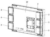
- FIG. 2 is a perspective view of the image display device as viewed from the back side.
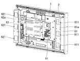
- FIG. 3 is a perspective view of the image display apparatus from which the rear wall of the case has been removed, as viewed from the rear side.
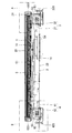
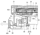
- FIG. 4 is a horizontal sectional view of the image display apparatus.
- FIG. 5 is a perspective view of a disassembled part of the image display device as viewed from the back side.
- FIG. 6 is a perspective view of a flow path forming member provided in the image display device.
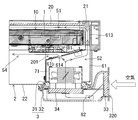
- FIG. 7 is an enlarged view of a region A shown in FIG.
- FIG. 8 is an enlarged view of a region B shown in FIG.
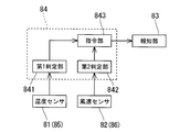
- FIG. 9 is a block diagram showing a configuration for notifying filter clogging in the image display apparatus.
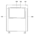
- FIG. 10 shows an embodiment of the image display apparatus.
- the image display device comprises a liquid crystal display panel (1) and a case (2) for housing the liquid crystal display panel (1).
- the front wall (21) of the housing (2) is provided with an image display window (20) for making the screen (10) of the liquid crystal display panel (1) visible from the outside.
- the image display window (20) is composed of a light transmission plate such as a glass plate.
- the liquid crystal display panel (1) is installed in the housing (2) by providing a gap between the screen (10) and the image display window (20).
- the case (2) further contains a circuit board (11) for controlling the liquid crystal display panel (1), and the circuit board (11) is a back surface of the liquid crystal display panel (1).
- a pair of left and right vents (31) and (41) communicating with the inside from the outside of the case (2) is opened in the back wall (22) of the case (2),
- a pair of duct portions (32) (42) are provided which respectively surround the pair of vent holes (31) (41).
- the pair of duct portions (32) (42) respectively extend laterally from the pair of vents (31) (41) along the back wall (22) of the housing (2) in opposite directions, and are open ends
- the parts (320) (420) are turned to the side.
- the pair of vents (3) (where the outside and the inside of the housing (2) are communicated with each other by the pair of vents (31) (41) and the pair of ducts (32) (42). 4) is configured.
- a pair of ventilation parts (3) and (4) is provided at three places, the upper stage, the middle stage and the lower stage of the back wall of the housing (2).
- the space between the screen (10) of the liquid crystal display panel (1) and the image display window (20) of the case (2) passes between A flow passage (5) for communicating the vents (31) (41) with each other is formed.
- the flow path (5) extends from the first flow path portion (51) extending along the screen (10) of the liquid crystal display panel (1), and the liquid crystal display panel from the first flow path portion (51) It is comprised from a pair of 2nd flow-path part (52) (53) which passes both the left-right both sides of (1), and is extended back, and a pair of 2nd flow-path parts (52) (53) are a pair, respectively. Vents (31) and (41).
- the first channel portion (51) is formed by the screen (10) of the liquid crystal display panel (1) and the image display window (20) of the housing (2). Further, as shown in FIG. 3, the pair of second flow path portions (52) and (53) are respectively formed by the pair of flow path forming members (61) and (62).
- the flow path forming member (61) on the right side (hereinafter simply referred to as "right side") as viewed from the back side is shown in FIG.
- the opening (611) is formed in three places of the upper stage, middle stage and lower stage of the back wall (61a), and as shown in FIG. 5, a slit-like passage (612) expanded vertically in the front wall (61b).
- a passage forming portion (613) for forming a hole is projected forward. Further, the three openings (611) (611) (611) and the passage (612) communicate with each other through the space in the flow path forming member (61) on the right side.
- the passage forming portion of the flow passage forming member (61) on the right side between the right side surface of the liquid crystal display panel (1) and the housing (2). (613) is inserted, whereby the space in the flow path forming member (61) on the right side, that is, the second flow path portion (52) leads to the first flow path portion (51).
- the three openings (611) (611) (611) formed in the flow path forming member (61) on the right side respectively correspond to the back wall (22) of the housing (2).
- the three air vents (31) (31) (31) (31) opened in the upper, middle, and lower three places of the) are opposed, and the space in the flow path forming member (61) on the right side is thereby opened. It leads to the space in the ventilation part (3) through (611) and the ventilation port (31).
- the front wall (61b) of the flow path forming member (61) on the right side is inclined with respect to the back surface of the liquid crystal display panel (1). Therefore, the second flow path portion (52) formed by the flow path forming member (61) on the right side has a shape gradually expanding rearward after passing through the right side surface of the liquid crystal display panel (1). doing.
- a gap (a space) around the center on the back side of the liquid crystal display panel (1) between the front wall (61b) of the flow path forming member (61) on the right and the back of the liquid crystal display panel (1) 201) is formed.
- the flow path forming member (62) on the left side (hereinafter simply referred to as "left side") seen from the back side is shown in FIG. Openings (621) are formed at three locations on the upper, middle and lower portions of the back wall (62a), and the front wall (62b) is the same as the flow path forming member (61) on the right (see FIG. 5)
- a passage forming portion (623) forming a slit-like passage which is expanded in the upper and lower direction is provided to project forward (see FIG. 4).
- the space in the left flow path forming member (62), that is, the second flow path portion (53) is communicated with the first flow path portion (51).
- the three openings (621) (621) (621) formed in the flow path forming member (62) on the left side are respectively the back wall (22) of the housing (2).
- the three air vents (41), (41), (41) opened in the upper, middle, and lower three places are facing each other, and the space in the flow path forming member (62) on the left side is thereby opened. It leads to the space in the vent (4) through (621) and the vent (41).
- the front wall (62b) of the flow passage forming member (62) on the left side is inclined with respect to the back surface of the liquid crystal display panel (1). Therefore, the second flow path portion (53) formed by the flow path forming member (62) on the left side has a shape which gradually spreads rearward after passing through the left side surface of the liquid crystal display panel (1). doing.
- a gap (a space) around the center on the back side of the liquid crystal display panel (1) between the front wall (62b) of the flow path forming member (62) on the left and the back of the liquid crystal display panel (1). 202) is formed.
- three through holes (614) (614) (614) are formed in the front wall (61 b) of the flow path forming member (61) on the right side.
- a gap (201) communicating with a space near the center on the back side of the liquid crystal display panel (1) is formed between the front wall (61b) and the back of the liquid crystal display panel (1). It is done. Therefore, as shown in FIG. 7, the second flow path portion (52) formed by the flow path forming member (61) on the right side is the back side of the liquid crystal display panel (1) through the respective through holes (614). It leads to the space of
- the front wall (62b) of the flow path forming member (62) on the left side three through holes (624) (624) (624) are formed (see FIG. 8).
- a gap (202) communicating with the space near the center on the back side of the liquid crystal display panel (1) is formed between the front wall (62b) and the back of the liquid crystal display panel (1). It is done. Therefore, as shown in FIG. 8, the second flow path portion (53) formed by the flow path forming member (62) on the left side is the back side of the liquid crystal display panel (1) through each through hole (624). It leads to the space of
- a flow path which passes through the front side of the liquid crystal display panel (1) and allows the pair of vents (31) (41) to communicate with each other
- a second flow path (54) is formed which allows the pair of vents (31) (41) to communicate with each other through the back side of the liquid crystal display panel (1).
- a blower fan (71) is in the housing (2) in the blowing direction. It is fitted in the posture toward the inside of the. Therefore, when the air blowing operation of the air blowing fan (71) is performed, the air in each duct portion (32) on the right side is in the second flow path portion (52) as shown by the solid line arrow in FIG. The air that has been sucked and sucked into the second flow passage (52) flows into the first flow passage (51) from the right end thereof.
- vent holes (41) on the left side opened in the back wall (22) of the housing (2) are fitted in a posture in which the air blowing direction is directed to the outside of the housing (2) . Therefore, when the air blowing operation of the air blowing fan (72) is performed, the air in the second flow path (53) flows into the ducts (42) on the left side as shown by solid arrows in FIG. The air in the first flow passage (51) is discharged from the left end of the first flow passage (51) and flows out into the second flow passage (53).
- a pair of filters (33) and (34) is installed in the duct portion (32) constituting the ventilation portion (3).
- one filter (33) is provided in the open end (320) of the duct portion (32) and the other filter (34) is ventilated It is provided in the area near the mouth (31), and a space is provided between these filters (33) and (34). That is, one filter (33) is provided in a region outside the installation region of the other filter (34) at a distance from the other filter (34).
- a pair of filters (43) and (44) is installed in the duct portion (42) constituting the ventilation portion (4).
- one filter (43) is provided in the open end (420) of the duct portion (42) and the other filter (44) is ventilated It is provided in a region near the mouth (41), and a space is provided between these filters (43) and (44). That is, one filter (43) is provided apart from the other filter (44) in an area outside the installation area of the other filter (44).
- a channel (5) is formed in the housing (2), which passes through the front side of the liquid crystal display panel (1) to allow the pair of vents (31) (41) to communicate with each other. ing. Further, when the air blowing operation of the two air blowing fans (71) and (72) is executed, in the flow path (5), the air vent (31) on the intake side goes to the air vent (41) on the exhaust side. The air flow is generated, and along with this, the air outside the housing (2) is sucked into the flow path (5) through the respective vents (3) on the intake side, and through the respective vents (4) on the exhaust side. Air in the flow path (5) is discharged to the outside of the housing (2).
- the air outside the housing (2) sucked into the flow path (5) flows between the screen (10) of the liquid crystal display panel (1) and the image display window (20) of the housing (2).
- the heat is absorbed from the screen (10) of the liquid crystal display panel (1).
- the air warmed by the absorbed heat is discharged to the outside of the housing (2) through the vents (4) on the exhaust side.
- the screen (10) of the liquid crystal display panel (1) is cooled by the air outside the housing (2).
- a second flow path (54) which causes the pair of vents (31) (41) to communicate with each other by passing through the back side of the liquid crystal display panel (1) in the housing (2).
- a second flow path (54) which causes the pair of vents (31) (41) to communicate with each other by passing through the back side of the liquid crystal display panel (1) in the housing (2).
- the air blowing operation of the two air blowing fans (71) and (72) is performed and the flow of air is generated in the flow path (5), the air is sucked through the air vents (3) on the intake side. Part of the air passes through the back side of the liquid crystal display panel (1), and is discharged from the vents (4) on the exhaust side to the outside of the housing (2).
- the liquid crystal display panel (1) is also cooled from the back side by air outside the housing (2), and as a result, the entire liquid crystal display panel (1) is efficiently cooled.
- the circuit board (11) installed on the back of the liquid crystal display panel (1) is cooled by the air outside the housing (2), and as a result, the circuit board (11) is prevented from being damaged by overheating. It will be.
- a pair of filters (33) and (34) is installed in the duct portion (32) which constitutes the ventilation portion (3) on the intake side. Therefore, dust, iron powder and the like contained in the air outside the casing (2) are removed by the pair of filters (33) and (34) when the air passes through the inside of the ventilation part (3). become. Therefore, air which hardly contains dust, iron powder and the like is sucked into the flow path (5).
- a pair of filters (43) and (44) is installed in the duct portion (42) that constitutes the vent portion (4) on the exhaust side. Therefore, dust, iron powder, etc. which are going to infiltrate into the flow path (5) from the ventilation part (4) are removed by the pair of filters (43) and (44).
- the failure of the liquid crystal display panel (1) caused by dust, iron powder and the like can be prevented.
- a pair of filters (33) and (34) are provided apart from each other. Therefore, the removal performance of the filter is improved as compared with the case where the pair of filters (33) and (34) are provided in contact with each other. The same applies to the pair of filters (43) and (44).
- the image display apparatus includes a temperature sensor (81) for acquiring temperature information that changes according to the temperature of the liquid crystal display panel (1), 3) A wind speed sensor (82) that acquires wind speed information that changes according to the speed of the air flowing inside, and a notification for performing a notification operation that reports that clogging has occurred in the filters (33) and (34) A control unit (84) for controlling the notification operation of the notification unit (83) based on the unit (83) and the temperature information acquired by the temperature sensor (81) and the wind speed information acquired by the wind speed sensor (82); It is further equipped.
- the temperature sensor (81) is installed in the flow passage forming member (61) on the intake side.
- the wind speed sensor (82) is installed in the area between the pair of filters (33) and (34) in the intake side ventilation section (3), according to the speed of the air discharged from the filter (33). To obtain the changing wind speed information. If the filter (33) is clogged, the speed of the air discharged through the filter (33) will be higher than that without clog.
- the control unit (84) is a first determination that determines whether the temperature of the liquid crystal display panel (1) is higher than a predetermined temperature based on temperature information acquired by the temperature sensor (81).
- a second determination unit (842) that determines whether the velocity of air flowing in the ventilation unit (3) is higher than a predetermined velocity based on wind speed information acquired by the unit (841) and the wind velocity sensor (82);
- a command unit (843) for commanding the notification unit (83) to execute the notification operation based on the determination results of the first determination unit (841) and the second determination unit (842).
- the command unit (843) causes the temperature of the liquid crystal display panel (1) to rise due to the occurrence of clogging in one of the pair of filters (33) and (34), and the first determination is made Section (841) determines that the temperature of the liquid crystal display panel (1) is higher than a predetermined temperature, or the filter (33) is clogged so that the speed of the air flowing in the intake section (3) on the intake side
- the notification unit (83) is instructed to execute the notification operation.
- temperature information that changes according to the temperature of the liquid crystal display panel (1) is acquired in the flow path forming member (62) on the exhaust side.
- a second wind speed is provided in which the second temperature sensor (85) is installed and wind speed information that changes in accordance with the speed of the air flowing in the ventilation section (4) in the ventilation section (4) on the exhaust side
- a sensor (86) is installed. Then, based on the temperature information acquired by the second temperature sensor (85) and the wind speed information acquired by the second wind speed sensor (86), the control similar to the control described above is performed by the control unit (84). Is executed (see FIG. 9).
- any one of the filters (33) and (34) in the ventilating portion (3) on the intake side and the filters (43) and (44) in the ventilating portion (4) on the exhaust side Immediately after the clogging occurs, the generation of the clogging is notified by the notification unit (83). Accordingly, it is possible to prevent the temperature of the liquid crystal display panel (1) from excessively rising due to the time of replacement of the filters (33) and (34).
- Embodiment of the Image Display Device The image display device described above can be mounted and used in a vending machine (101) installed outdoors, as shown in FIG. In FIG. 10, the image display device is indicated by reference numeral (100).
- the vending machine (101) is provided with a window (102) for mounting the image display device (100), and both sides of the mounting area of the image display device (100) are extended to the bottom of the vending machine (101).
- a pair of extending second duct sections (103) (104) is provided.
- the air outside the vending machine (101) is in the flow path (5) of the image display device (100) through the pair of duct portions (103) and (104) of the vending machine (101). While being sucked, the air in the flow path (5) is exhausted to the outside of the vending machine (101). As a result, the normal operation of the image display apparatus (100) is maintained also in the vending machine (101).
- the pair of second flow path portions (52) and (53) extends rearward from the first flow path portion (51) while passing through the left and right sides of the liquid crystal display panel (1).
- the present invention is not limited to this.
- the pair of second flow path portions (52) (53) may extend rearward from the first flow path portion (51) by passing both the upper and lower sides of the liquid crystal display panel (1).
- the pair of air vents (31) (41) are provided in the rear wall (22) of the housing (2) in a positional relationship in line with the left and right. It is not limited to For example, the pair of air vents (31) (41) may be opened in the back wall (22) of the housing (2) in a positional relationship vertically aligned, or in both side walls of the housing (2) Each may be opened.
- the image display apparatus may have a configuration in which only one of the blower fans (71) and (72) is provided.
- the control unit (84) performs the notification operation of the notification unit (83) based only on information acquired by one of the temperature sensor (81) and the wind speed sensor (82). May be controlled.
- the control unit (84) reports on the notification unit (83) based only on information acquired by any one of the second temperature sensor (85) and the second wind speed sensor (86). It can control the operation.
- various configurations adopted for the image display device are not limited to the image display device having the liquid crystal display panel (1), and various image display panels such as a plasma display panel and an organic EL (Electro-Luminescence) display panel. Can be applied to an image display apparatus provided with
Landscapes
- Engineering & Computer Science (AREA)
- Multimedia (AREA)
- Signal Processing (AREA)
- Devices For Indicating Variable Information By Combining Individual Elements (AREA)
- Cooling Or The Like Of Electrical Apparatus (AREA)
Abstract
本発明に係る画像表示装置は、画像表示パネル(1)と、該画像表示パネルを収容する筐体(2)とを具え、該筐体には、画像表示パネルの画面(10)を外部から視認可能にする画像表示窓(20)が設けられている。ここ で、筐体には、該筐体の外部から内部に通じる一対の通気口(31)(41)が開設されると共に、画像表示パネルの画面と筐体の画像表示窓との間を通過して一対の通気口どうしを連通させる流路(5)が形成されており、筐体には更に、流路内に空気の流れを発生させる送風ファン(71)(72)が配備されている。
Description
本発明は、画像表示パネルを具えた画像表示装置に関する。
この種の画像表示装置は、画像表示パネルを収容する筐体を具え、該筐体には、画像表示パネルの画面を外部から視認可能にする画像表示窓が設けられている(例えば、特開2005-286987号公報参照)。
従来の画像表示装置は、その殆どが屋内に設置することを前提として設計されたものであり、画像表示窓から太陽光が入射して画像表示パネルの画面が該太陽光によって加熱されることは、想定されていない。
ところで、近年、画像表示パネルを具えた画像表示装置を屋外に常設することや、該画像表示装置を屋外に設置されている自動販売機等の他の装置内に搭載することが考えられている。画像表示装置はその厚さ寸法が小さいため、狭い場所への画像表示装置の設置が可能であり、又、自動販売機等の他の装置内に搭載しても該装置が大型化し難い。
しかしながら、従来の画像表示装置をそのまま屋外に常設し、或いは従来の画像表示装置をそのまま自動販売機等の他の装置内に搭載した場合、画像表示窓から太陽光が入射することにより、画像表示パネルの画面の温度が過度に上昇して画像表示パネルの動作に異常が発生する虞がある。
本発明に係る第1の画像表示装置は、画像表示パネルと、該画像表示パネルを収容する筐体とを具え、該筐体には、画像表示パネルの画面を外部から視認可能にする画像表示窓が設けられている。
ここで、前記筐体には、該筐体の外部から内部に通じる一対の通気口が開設されると共に、前記画像表示パネルの画面と筐体の画像表示窓との間を通過して前記一対の通気口どうしを連通させる流路が形成されており、前記筐体には更に、前記流路内に空気の流れを発生させる送風手段が配備されている。
ここで、前記筐体には、該筐体の外部から内部に通じる一対の通気口が開設されると共に、前記画像表示パネルの画面と筐体の画像表示窓との間を通過して前記一対の通気口どうしを連通させる流路が形成されており、前記筐体には更に、前記流路内に空気の流れを発生させる送風手段が配備されている。
本発明に係る第2の画像表示装置は、画像表示パネルと、該画像表示パネルを収容する筐体とを具え、該筐体には、画像表示パネルの画面を外部から視認可能にする画像表示窓が設けられている。
ここで、前記筐体には、該筐体の外部と内部とを互いに連通させる通気部が形成されると共に、該通気部から筐体内へ空気を導く送風手段が配備され、前記通気部内には一対のフィルタが設置されており、該一対のフィルタの内、一方のフィルタは、他方のフィルタの設置領域より外側の領域に該他方のフィルタから離間して設けられている。
ここで、前記筐体には、該筐体の外部と内部とを互いに連通させる通気部が形成されると共に、該通気部から筐体内へ空気を導く送風手段が配備され、前記通気部内には一対のフィルタが設置されており、該一対のフィルタの内、一方のフィルタは、他方のフィルタの設置領域より外側の領域に該他方のフィルタから離間して設けられている。
以下、本発明の実施の形態につき、図面に沿って具体的に説明する。
1.画像表示装置の構成
図1に示す様に、本発明の一実施形態に係る画像表示装置は、液晶表示パネル(1)と、該液晶表示パネル(1)を収容する筐体(2)とを具え、該筐体(2)の前面壁(21)には、液晶表示パネル(1)の画面(10)を外部から視認可能にする画像表示窓(20)が設けられている。ここで、画像表示窓(20)は、ガラス板等の光透過板から構成されている。又、液晶表示パネル(1)は、その画面(10)と画像表示窓(20)との間に隙間を設けて筐体(2)内に設置されている。
1.画像表示装置の構成
図1に示す様に、本発明の一実施形態に係る画像表示装置は、液晶表示パネル(1)と、該液晶表示パネル(1)を収容する筐体(2)とを具え、該筐体(2)の前面壁(21)には、液晶表示パネル(1)の画面(10)を外部から視認可能にする画像表示窓(20)が設けられている。ここで、画像表示窓(20)は、ガラス板等の光透過板から構成されている。又、液晶表示パネル(1)は、その画面(10)と画像表示窓(20)との間に隙間を設けて筐体(2)内に設置されている。
図3に示す様に、筐体(2)には更に、液晶表示パネル(1)を制御する回路基板(11)が収容され、該回路基板(11)は、液晶表示パネル(1)の背面に設置されている。
図4に示す様に、筐体(2)を背面壁(22)には、該筐体(2)の外部から内部に通じる左右一対の通気口(31)(41)が開設されると共に、該一対の通気口(31)(41)をそれぞれ包囲する一対のダクト部(32)(42)が設置されている。該一対のダクト部(32)(42)はそれぞれ、一対の通気口(31)(41)から筐体(2)の背面壁(22)に沿って互いに反対向きに側方へ延び、開口端部(320)(420)を側方に向けている。斯くして、一対の通気口(31)(41)と一対のダクト部(32)(42)とによって、筐体(2)の外部と内部とを互いに連通させる一対の通気部(3)(4)が構成されている。
本実施形態においては、図2に示す様に、筐体(2)の背面壁の上段、中段、下段の3箇所に一対の通気部(3)(4)が設けられている。
図4に示す様に、筐体(2)の内部には、液晶表示パネル(1)の画面(10)と筐体(2)の画像表示窓(20)との間を通過して一対の通気口(31)(41)どうしを連通させる流路(5)が形成されている。具体的には、該流路(5)は、液晶表示パネル(1)の画面(10)に沿って延びる第1流路部(51)と、第1流路部(51)から液晶表示パネル(1)の左右両側を通過して後方へ延びる一対の第2流路部(52)(53)とから構成されており、該一対の第2流路部(52)(53)はそれぞれ一対の通気口(31)(41)に通じている。
ここで、第1流路部(51)は、液晶表示パネル(1)の画面(10)と筐体(2)の画像表示窓(20)とによって形成されている。又、一対の第2流路部(52)(53)はそれぞれ、図3に示す様に一対の流路形成部材(61)(62)によって形成されている。
一対の流路形成部材(61)(62)の内、背面側から見て右側(以下、単に「右側」と呼ぶ。)の流路形成部材(61)には、図3に示す様にその背面壁(61a)の上段、中段、下段の3箇所に開口(611)が形成されると共に、図5に示す様にその前面壁(61b)に、上下に拡がったスリット状の通路(612)を形成する通路形成部(613)が前方へ突設されている。又、3つの開口(611)(611)(611)と通路(612)とは、右側の流路形成部材(61)内の空間を介して互いに連通している。
図4及び図7に示す様に画像表示装置の組立て状態においては、液晶表示パネル(1)の右側面と筐体(2)との間に右側の流路形成部材(61)の通路形成部(613)が貫挿され、これにより右側の流路形成部材(61)内の空間、即ち第2流路部(52)が、第1流路部(51)に通じることになる。又、画像表示装置の組立て状態においては、右側の流路形成部材(61)に形成されている3つの開口(611)(611)(611)がそれぞれ、筐体(2)の背面壁(22)の上段、中段、下段の3箇所に開設されている3つの通気口(31)(31)(31)に対向し、これにより右側の流路形成部材(61)内の空間が、各開口(611)と通気口(31)とを介して通気部(3)内の空間に通じることになる。
ここで、図7に示す様に、右側の流路形成部材(61)の前面壁(61b)は、液晶表示パネル(1)の背面に対して傾斜している。従って、右側の流路形成部材(61)によって形成される第2流路部(52)は、液晶表示パネル(1)の右側面を通過した後、後方へ向けて徐々に拡がった形状を有している。又、右側の流路形成部材(61)の前面壁(61b)と液晶表示パネル(1)の背面との間には、液晶表示パネル(1)の背面側の中央付近の空間に通じる隙間(201)が形成されている。
一対の流路形成部材(61)(62)の内、背面側から見て左側(以下、単に「左側」と呼ぶ。)の流路形成部材(62)には、図3に示す様にその背面壁(62a)の上段、中段、下段の3箇所に開口(621)が形成されると共に、その前面壁(62b)に、右側の流路形成部材(61)と同様(図5参照)、上下に拡がったスリット状の通路を形成する通路形成部(623)が前方へ突設されている(図4参照)。
図4に示す様に画像表示装置の組立て状態においては、液晶表示パネル(1)の左側面と筐体(2)との間に左側の流路形成部材(62)の通路形成部(623)が貫挿され、これにより左側の流路形成部材(62)内の空間、即ち第2流路部(53)が、第1流路部(51)に通じることになる。又、画像表示装置の組立て状態においては、左側の流路形成部材(62)に形成されている3つの開口(621)(621)(621)がそれぞれ、筐体(2)の背面壁(22)の上段、中段、下段の3箇所に開設されている3つの通気口(41)(41)(41)に対向し、これにより左側の流路形成部材(62)内の空間が、各開口(621)と通気口(41)とを介して通気部(4)内の空間に通じることになる。
ここで、図8に示す様に、左側の流路形成部材(62)の前面壁(62b)は、液晶表示パネル(1)の背面に対して傾斜している。従って、左側の流路形成部材(62)によって形成される第2流路部(53)は、液晶表示パネル(1)の左側面を通過した後、後方へ向けて徐々に拡がった形状を有している。又、左側の流路形成部材(62)の前面壁(62b)と液晶表示パネル(1)の背面との間には、液晶表示パネル(1)の背面側の中央付近の空間に通じる隙間(202)が形成されている。
更に、図6に示す様に、右側の流路形成部材(61)の前面壁(61b)には、3つの貫通孔(614)(614)(614)が形成されている。ここで、上述した様に、前面壁(61b)と液晶表示パネル(1)の背面との間には、液晶表示パネル(1)の背面側の中央付近の空間に通じる隙間(201)が形成されている。従って、図7に示す様に、右側の流路形成部材(61)によって形成される第2流路部(52)は、各貫通孔(614)を介して液晶表示パネル(1)の背面側の空間に通じている。
同様に、左側の流路形成部材(62)の前面壁(62b)には、3つの貫通孔(624)(624)(624)が形成されている(図8参照)。ここで、上述した様に、前面壁(62b)と液晶表示パネル(1)の背面との間には、液晶表示パネル(1)の背面側の中央付近の空間に通じる隙間(202)が形成されている。従って、図8に示す様に、左側の流路形成部材(62)によって形成される第2流路部(53)は、各貫通孔(624)を介して液晶表示パネル(1)の背面側の空間に通じている。
この様に、筐体(2)の内部には、図4に示す様に、液晶表示パネル(1)の前面側を通過して一対の通気口(31)(41)どうしを連通させる流路(5)の他に、液晶表示パネル(1)の背面側を通過して一対の通気口(31)(41)どうしを連通させる第2の流路(54)が形成されている。
図4に示す様に、筐体(2)の背面壁(22)に開設されている右側の各通気口(31)には、送風ファン(71)が、その送風方向を筐体(2)の内側へ向けた姿勢で嵌合されている。従って、送風ファン(71)の送風動作が実行されることにより、図7にて実線矢印によって示す様に、右側の各ダクト部(32)内の空気が第2流路部(52)内に吸入され、第2流路部(52)内に吸入された空気は、第1流路部(51)内へその右端から流れ込むことになる。
一方、筐体(2)の背面壁(22)に開設されている左側の各通気口(41)には、その送風方向を筐体(2)の外側へ向けた姿勢で嵌合されている。従って、送風ファン(72)の送風動作が実行されることにより、図8にて実線矢印によって示す様に、左側の各ダクト部(42)内へ第2流路部(53)内の空気が排出され、これに伴って第1流路部(51)内の空気が、第1流路部(51)の左端から第2流路部(53)内へ流れ出ることになる。
これにより、第1流路部(51)内には、図4にて実線矢印によって示す様に、右から左へ向かう空気の流れが発生し、その結果、流路(5)内には、右側の通気口(31)から左側の通気口(41)へ向かう空気の流れが発生することになる。この様に流路(5)内に空気の流れが発生することにより、右側の各通気部(3)を通じて筐体(2)外部の空気が第2流路部(52)内に吸入され、左側の各通気部(4)を通じて第2流路部(53)内の空気が筐体(2)の外部へ排出されることになる。
又、2つの送風ファン(71)(72)の送風動作が実行されて流路(5)内に空気の流れが発生するのに伴って、右側の各通気部(3)を通じて吸入された空気の一部が、液晶表示パネル(1)の背面側を通過して、左側の各通気部(4)から筐体(2)の外部へ排出されることになる。尚、以下では、「右側」を「吸気側」と称し、「左側」を「排気側」と称す。
図7に示す様に、通気部(3)を構成するダクト部(32)内には、一対のフィルタ(33)(34)が設置されている。具体的には、該一対のフィルタ(33)(34)の内、一方のフィルタ(33)はダクト部(32)の開口端部(320)内に設けられ、他方のフィルタ(34)は通気口(31)近傍の領域に設けられており、これらのフィルタ(33)(34)の間には空間が設けられている。即ち、一方のフィルタ(33)は、他方のフィルタ(34)の設置領域より外側の領域に該他方のフィルタ(34)から離間して設けられている。
図8に示す様に、通気部(4)を構成するダクト部(42)内には、一対のフィルタ(43)(44)が設置されている。具体的には、該一対のフィルタ(43)(44)の内、一方のフィルタ(43)はダクト部(42)の開口端部(420)内に設けられ、他方のフィルタ(44)は通気口(41)近傍の領域に設けられており、これらのフィルタ(43)(44)の間には空間が設けられている。即ち、一方のフィルタ(43)は、他方のフィルタ(44)の設置領域より外側の領域に該他方のフィルタ(44)から離間して設けられている。
上記画像表示装置においては、筐体(2)内に、液晶表示パネル(1)の前面側を通過して一対の通気口(31)(41)どうしを連通させる流路(5)が形成されている。又、2つの送風ファン(71)(72)の送風動作が実行されることにより、流路(5)内には、吸気側の通気口(31)から排気側の通気口(41)へ向かう空気の流れが発生し、これに伴って吸気側の各通気部(3)を通じて筐体(2)外部の空気が流路(5)内に吸入され、排気側の各通気部(4)を通じて流路(5)内の空気が筐体(2)の外部へ排出される。
従って、流路(5)内に吸入された筐体(2)外部の空気が、液晶表示パネル(1)の画面(10)と筐体(2)の画像表示窓(20)との間を通過し、その際に液晶表示パネル(1)の画面(10)から熱を吸収する。そして、吸収した熱によって温められた空気は、排気側の各通気部(4)を通じて筐体(2)の外部へ排出される。これにより、液晶表示パネル(1)の画面(10)は、筐体(2)外部の空気によって冷却されることになる。よって、画像表示窓(20)から太陽光が入射して液晶表示パネル(1)の画面(10)が該太陽光によって加熱された場合でも、液晶表示パネル(1)の画面(10)の温度上昇が抑制され、その結果、液晶表示パネル(1)の正常な動作が維持されることになる。
上記画像表示装置においては、筐体(2)内に更に、液晶表示パネル(1)の背面側を通過して一対の通気口(31)(41)どうしを連通させる第2の流路(54)が形成されている。又、2つの送風ファン(71)(72)の送風動作が実行されて流路(5)内に空気の流れが発生するのに伴って、吸気側の各通気部(3)を通じて吸入された空気の一部が、液晶表示パネル(1)の背面側を通過して、排気側の各通気部(4)から筐体(2)の外部へ排出される。
従って、液晶表示パネル(1)は、筐体(2)外部の空気によって背面側からも冷却され、その結果、液晶表示パネル(1)全体が効率良く冷却されることになる。又、液晶表示パネル(1)の背面に設置されている回路基板(11)が、筐体(2)外部の空気によって冷却され、その結果、過熱による回路基板(11)の破損が防止されることになる。
上記画像表示装置においては、吸気側の通気部(3)を構成するダクト部(32)内に、一対のフィルタ(33)(34)が設置されている。従って、筐体(2)外部の空気中に含まれる塵や鉄粉等は、該空気が通気部(3)内を通過する際に、一対のフィルタ(33)(34)によって除去されることになる。従って、流路(5)内には、塵や鉄粉等を殆ど含まない空気が吸入されることとなる。
又、排気側の通気部(4)を構成するダクト部(42)内にも、一対のフィルタ(43)(44)が設置されている。従って、通気部(4)から流路(5)内へ浸入しようとする塵や鉄粉等が、一対のフィルタ(43)(44)によって除去されることになる。
よって、上記画像表示装置によれば、塵や鉄粉等が原因となって生じる液晶表示パネル(1)の故障が防止されることになる。
更に、上記画像表示装置においては、一対のフィルタ(33)(34)が互いに離間して設けられている。よって、該一対のフィルタ(33)(34)を互いに接触させて設けた場合に比べて、フィルタの除去性能が向上している。一対のフィルタ(43)(44)についても同様である。
2.フィルタの目詰まりを報知するための構成
吸気側の通気部(3)内に設置されている一対のフィルタ(33)(34)には、これらのフィルタ(33)(34)によって除去された塵や鉄粉等が堆積することになる。塵や鉄粉等の堆積量が増えるとフィルタ(33)(34)に目詰まりが生じて、流路(5)内への空気の吸入がフィルタ(33)(34)によって妨げられることになる。これにより、流路(5)内への空気の吸入量が減少し、液晶表示パネル(1)の温度が上昇することになる。フィルタ(33)(34)に目詰まりが生じた場合には、フィルタを交換する必要がある一方で、交換時期を逸すると液晶表示パネル(1)の温度が過度に上昇して液晶表示パネル(1)の動作に異常が発生し易くなる。排気側の通気部(4)内に設置されているフィルタ(43)(44)に目詰まりが生じて、流路(5)内からの空気の排出量が減少した場合も、同様である。
吸気側の通気部(3)内に設置されている一対のフィルタ(33)(34)には、これらのフィルタ(33)(34)によって除去された塵や鉄粉等が堆積することになる。塵や鉄粉等の堆積量が増えるとフィルタ(33)(34)に目詰まりが生じて、流路(5)内への空気の吸入がフィルタ(33)(34)によって妨げられることになる。これにより、流路(5)内への空気の吸入量が減少し、液晶表示パネル(1)の温度が上昇することになる。フィルタ(33)(34)に目詰まりが生じた場合には、フィルタを交換する必要がある一方で、交換時期を逸すると液晶表示パネル(1)の温度が過度に上昇して液晶表示パネル(1)の動作に異常が発生し易くなる。排気側の通気部(4)内に設置されているフィルタ(43)(44)に目詰まりが生じて、流路(5)内からの空気の排出量が減少した場合も、同様である。
そこで、本実施形態に係る画像表示装置は、図9に示す様に、液晶表示パネル(1)の温度に応じて変化する温度情報を取得する温度センサ(81)と、吸気側の通気部(3)内を流れる空気の速度に応じて変化する風速情報を取得する風速センサ(82)と、フィルタ(33)(34)に目詰まりが発生したことを報知する報知動作を実行するための報知部(83)と、温度センサ(81)により取得される温度情報及び風速センサ(82)により取得される風速情報に基づいて報知部(83)の報知動作を制御する制御部(84)とを更に具えている。
ここで、図7に示す様に、温度センサ(81)は、吸気側の流路形成部材(61)内に設置されている。又、風速センサ(82)は、吸気側の通気部(3)内にて、一対のフィルタ(33)(34)間の領域に設置され、フィルタ(33)から排出される空気の速度に応じて変化する風速情報を取得する。尚、フィルタ(33)に目詰まりが生じると、フィルタ(33)を通過して排出される空気の速度は、目詰まりのないときに比べて大きくなる。
制御部(84)は、図9に示す様に、温度センサ(81)により取得される温度情報に基づいて液晶表示パネル(1)の温度が所定温度より高いか否かを判定する第1判定部(841)と、風速センサ(82)により取得される風速情報に基づいて通気部(3)内を流れる空気の速度が所定速度より大きいか否かを判定する第2判定部(842)と、第1判定部(841)と第2判定部(842)の判定結果に基づいて報知部(83)に報知動作の実行を指令する指令部(843)とを含んでいる。
具体的には、指令部(843)は、一対のフィルタ(33)(34)の何れか一方のフィルタに目詰まりが生じることにより液晶表示パネル(1)の温度が上昇して、第1判定部(841)によって液晶表示パネル(1)の温度が所定温度より高いと判定されるか、又はフィルタ(33)に目詰まりが生じることにより吸気側の通気部(3)内を流れる空気の速度が大きくなって、第2判定部(842)によって該通気部(3)内を流れる空気の速度が所定速度より大きいと判定されたとき、報知部(83)に報知動作の実行を指令する。
本実施形態に係る画像表示装置においては、図8に示す様に、排気側の流路形成部材(62)内に、液晶表示パネル(1)の温度に応じて変化する温度情報を取得する第2の温度センサ(85)が設置されると共に、排気側の通気部(4)内に、該通気部(4)内を流れる空気の速度に応じて変化する風速情報を取得する第2の風速センサ(86)が設置されている。そして、制御部(84)によって、上述した制御と同様の制御が、第2の温度センサ(85)により取得される温度情報及び第2の風速センサ(86)により取得される風速情報に基づいて実行される(図9参照)。
上記画像表示装置によれば、吸気側の通気部(3)内のフィルタ(33)(34)及び排気側の通気部(4)内のフィルタ(43)(44)の何れかのフィルタに目詰まりが生じた直後に、該目詰まりの発生が報知部(83)によって報知されることになる。よって、フィルタ(33)(34)の交換時期を逸して液晶表示パネル(1)の温度が過度に上昇することが防止されることになる。
3.上記画像表示装置の実施例
上述した画像表示装置は、図10に示す様に、屋外に設置されている自動販売機(101)に搭載して使用することが出来る。尚、図10では、画像表示装置を符号(100)により示している。自動販売機(101)には、画像表示装置(100)を取り付けるための窓(102)が形成されると共に、画像表示装置(100)の搭載領域の両側を自動販売機(101)の底面まで延びる一対の第2のダクト部(103)(104)が配備されている。該一対の第2のダクト部(103)(104)の下端部は何れも自動販売機(101)の底面に開口し、該一対の第2のダクト部(103)(104)の上端部はそれぞれ、画像表示装置(100)に設けられている左右のダクト部(32)(42)との接続が可能な形状を有している。
上述した画像表示装置は、図10に示す様に、屋外に設置されている自動販売機(101)に搭載して使用することが出来る。尚、図10では、画像表示装置を符号(100)により示している。自動販売機(101)には、画像表示装置(100)を取り付けるための窓(102)が形成されると共に、画像表示装置(100)の搭載領域の両側を自動販売機(101)の底面まで延びる一対の第2のダクト部(103)(104)が配備されている。該一対の第2のダクト部(103)(104)の下端部は何れも自動販売機(101)の底面に開口し、該一対の第2のダクト部(103)(104)の上端部はそれぞれ、画像表示装置(100)に設けられている左右のダクト部(32)(42)との接続が可能な形状を有している。
上記実施例によれば、自動販売機(101)の一対のダクト部(103)(104)を通じて、画像表示装置(100)の流路(5)内に自動販売機(101)外部の空気が吸入されると共に、流路(5)内の空気が自動販売機(101)の外部へ排出されることになる。これにより、自動販売機(101)においても、画像表示装置(100)の正常な動作が維持されることになる。
尚、本発明の各部構成は上記実施の形態に限らず、特許請求の範囲に記載の技術的範囲内で種々の変形が可能である。上記画像表示装置においては、一対の第2流路部(52)(53)は、第1流路部(51)から液晶表示パネル(1)の左右両側を通過して後方へ延びていたが、本発明はこれに限られるものではない。例えば、一対の第2流路部(52)(53)は、第1流路部(51)から液晶表示パネル(1)の上下両側を通過して後方へ延びていてもよい。
又、上記画像表示装置においては、一対の通気口(31)(41)は、左右に並んだ位置関係で筐体(2)の背面壁(22)に開設されていたが、本発明はこれに限られるものではない。例えば、一対の通気口(31)(41)は、上下に並んだ位置関係で筐体(2)の背面壁(22)に開設されていてもよいし、筐体(2)の両側面壁にそれぞれ開設されていてもよい。
更に、上記画像表示装置は、送風ファン(71)(72)の内、何れか一方の送風ファンのみが設けられた構成を有していてもよい。又、上記画像表示装置において、制御部(84)は、温度センサ(81)及び風速センサ(82)の内、何れか一方のセンサが取得する情報のみに基づいて報知部(83)の報知動作を制御してもよい。同様に、制御部(84)は、第2の温度センサ(85)及び第2の風速センサ(86)の内、何れか一方のセンサが取得する情報のみに基づいて報知部(83)の報知動作を制御することが出来る。
更に又、上記画像表示装置に採用した各種構成は、液晶表示パネル(1)を具えた画像表示装置に限らず、プラズマ表示パネルや有機EL(Electro-Luminescence)表示パネル等、種々の画像表示パネルを具えた画像表示装置に適用することが出来る。
Claims (8)
- 画像表示パネルと、該画像表示パネルを収容する筐体とを具え、該筐体には、画像表示パネルの画面を外部から視認可能にする画像表示窓が設けられている画像表示装置において、
前記筐体には、該筐体の外部から内部に通じる一対の通気口が開設されると共に、前記画像表示パネルの画面と筐体の画像表示窓との間を通過して前記一対の通気口どうしを連通させる流路が形成されており、前記筐体には更に、前記流路内に空気の流れを発生させる送風手段が配備されていることを特徴とする画像表示装置。 - 前記筐体には、前記画像表示パネルの背面側を通過して前記一対の通気口どうしを連通させる第2の流路が形成されている請求項1に記載の画像表示装置。
- 前記画像表示パネルの画面と筐体の画像表示窓との間を通過する前記流路は、前記画像表示パネルの画面に沿って延びる第1流路部と、該第1流路部から画像表示パネルの左右両側又は上下両側を通過して後方へ延びる一対の第2流路部とを有し、前記筐体には、前記一対の第2流路部をそれぞれ形成する一対の流路形成部材が配備され、各流路形成部材には、画像表示パネルの背面側に通じる貫通孔が形成されている請求項2に記載の画像表示装置。
- 前記一対の通気口の内、少なくとも何れか一方の通気口に前記送風手段が設けられている請求項1に記載の画像表示装置。
- 画像表示パネルと、該画像表示パネルを収容する筐体とを具え、該筐体には、画像表示パネルの画面を外部から視認可能にする画像表示窓が設けられている画像表示装置において、
前記筐体には、該筐体の外部と内部とを互いに連通させる通気部が形成されると共に、該通気部から筐体内へ空気を導く送風手段が配備され、前記通気部内には一対のフィルタが設置されており、該一対のフィルタの内、一方のフィルタは、他方のフィルタの設置領域より外側の領域に該他方のフィルタから離間して設けられていることを特徴とする画像表示装置。 - 画像表示パネルの温度に応じて変化する温度情報を取得する温度センサ、及び/又は通気部内を流れる空気の速度に応じて変化する風速情報を取得する風速センサと、前記フィルタに目詰まりが発生したことを報知する報知動作を実行するための報知手段と、前記温度センサにより取得される温度情報及び/又は風速センサにより取得される風速情報に基づいて前記報知手段の報知動作を制御する制御手段とを更に具える請求項5に記載の画像表示装置。
- 表示パネルと、
該表示パネルの前面に配置された光透過部材と、
前記表示パネルと光透過部材の間の空間に空気流を発生させる発生部
とを具え、前記発生部は、前記表示パネルの一方の側面側に配置された排気用ファンを含む、表示装置。 - 前記発生部は、前記表示パネルの他方の側面側に配置された吸気用ファンを更に含む、請求項7に記載の表示装置。
Priority Applications (1)
| Application Number | Priority Date | Filing Date | Title |
|---|---|---|---|
| US13/516,616 US20120255704A1 (en) | 2009-12-18 | 2010-12-08 | Image display apparatus |
Applications Claiming Priority (4)
| Application Number | Priority Date | Filing Date | Title |
|---|---|---|---|
| JP2009287844A JP2011128432A (ja) | 2009-12-18 | 2009-12-18 | 画像表示装置 |
| JP2009-287845 | 2009-12-18 | ||
| JP2009287845A JP2011128433A (ja) | 2009-12-18 | 2009-12-18 | 画像表示装置 |
| JP2009-287844 | 2009-12-18 |
Publications (1)
| Publication Number | Publication Date |
|---|---|
| WO2011074455A1 true WO2011074455A1 (ja) | 2011-06-23 |
Family
ID=44167212
Family Applications (1)
| Application Number | Title | Priority Date | Filing Date |
|---|---|---|---|
| PCT/JP2010/072005 Ceased WO2011074455A1 (ja) | 2009-12-18 | 2010-12-08 | 画像表示装置 |
Country Status (2)
| Country | Link |
|---|---|
| US (1) | US20120255704A1 (ja) |
| WO (1) | WO2011074455A1 (ja) |
Cited By (1)
| Publication number | Priority date | Publication date | Assignee | Title |
|---|---|---|---|---|
| JP2017514156A (ja) * | 2014-06-18 | 2017-06-01 | キーウィン ディスプレイ カンパニー、リミテッド | 表示モジュールの放熱構造 |
Families Citing this family (36)
| Publication number | Priority date | Publication date | Assignee | Title |
|---|---|---|---|---|
| US12185512B2 (en) | 2007-11-16 | 2024-12-31 | Manufacturing Resources International, Inc. | Electronic display assembly with thermal management |
| US8854595B2 (en) | 2008-03-03 | 2014-10-07 | Manufacturing Resources International, Inc. | Constricted convection cooling system for an electronic display |
| US8497972B2 (en) | 2009-11-13 | 2013-07-30 | Manufacturing Resources International, Inc. | Thermal plate with optional cooling loop in electronic display |
| US8654302B2 (en) | 2008-03-03 | 2014-02-18 | Manufacturing Resources International, Inc. | Heat exchanger for an electronic display |
| US8773633B2 (en) | 2008-03-03 | 2014-07-08 | Manufacturing Resources International, Inc. | Expanded heat sink for electronic displays |
| US8693185B2 (en) | 2008-03-26 | 2014-04-08 | Manufacturing Resources International, Inc. | System and method for maintaining a consistent temperature gradient across an electronic display |
| US8749749B2 (en) | 2008-12-18 | 2014-06-10 | Manufacturing Resources International, Inc. | System for cooling an electronic image assembly with manifolds and ambient gas |
| US10827656B2 (en) | 2008-12-18 | 2020-11-03 | Manufacturing Resources International, Inc. | System for cooling an electronic image assembly with circulating gas and ambient gas |
| EP2909829B1 (en) | 2012-10-16 | 2020-02-12 | Manufacturing Resources International, INC. | Back pan cooling assembly for electronic display |
| WO2014149773A1 (en) | 2013-03-15 | 2014-09-25 | Manufacturing Resources International, Inc. | Heat exchange assembly for an electronic display |
| WO2014150036A1 (en) * | 2013-03-15 | 2014-09-25 | Manufacturing Resources International, Inc. | Cooling system for an electronic display |
| KR101894027B1 (ko) | 2013-07-08 | 2018-08-31 | 매뉴팩처링 리소시스 인터내셔널 인코포레이티드 | 전자 디스플레이용 8자 모양의 폐쇄형 루프 냉각 시스템 |
| WO2015138609A2 (en) | 2014-03-11 | 2015-09-17 | Manufacturing Resources International, Inc. | Hybrid rear cover and mounting bracket for eletronic display |
| KR101885884B1 (ko) | 2014-04-30 | 2018-08-07 | 매뉴팩처링 리소시스 인터내셔널 인코포레이티드 | 백투백 전자 디스플레이 어셈블리 |
| US9613548B2 (en) | 2015-01-06 | 2017-04-04 | Manufacturing Resources International, Inc. | Advanced cooling system for electronic display |
| US9723765B2 (en) | 2015-02-17 | 2017-08-01 | Manufacturing Resources International, Inc. | Perimeter ventilation system for electronic display |
| ES2909480T3 (es) | 2016-03-04 | 2022-05-06 | Mri Inc | Sistema de refrigeración para conjunto de pantalla de doble cara |
| US10485113B2 (en) | 2017-04-27 | 2019-11-19 | Manufacturing Resources International, Inc. | Field serviceable and replaceable display |
| JP6824440B2 (ja) | 2017-04-27 | 2021-02-03 | マニュファクチャリング・リソーシズ・インターナショナル・インコーポレーテッド | ディスプレイの曲げ変形を防止するためのシステムおよび方法 |
| US10559965B2 (en) | 2017-09-21 | 2020-02-11 | Manufacturing Resources International, Inc. | Display assembly having multiple charging ports |
| US10602626B2 (en) | 2018-07-30 | 2020-03-24 | Manufacturing Resources International, Inc. | Housing assembly for an integrated display unit |
| US11096317B2 (en) | 2019-02-26 | 2021-08-17 | Manufacturing Resources International, Inc. | Display assembly with loopback cooling |
| US10795413B1 (en) | 2019-04-03 | 2020-10-06 | Manufacturing Resources International, Inc. | Electronic display assembly with a channel for ambient air in an access panel |
| US11477923B2 (en) | 2020-10-02 | 2022-10-18 | Manufacturing Resources International, Inc. | Field customizable airflow system for a communications box |
| US11470749B2 (en) | 2020-10-23 | 2022-10-11 | Manufacturing Resources International, Inc. | Forced air cooling for display assemblies using centrifugal fans |
| US11778757B2 (en) | 2020-10-23 | 2023-10-03 | Manufacturing Resources International, Inc. | Display assemblies incorporating electric vehicle charging equipment |
| US11966263B2 (en) | 2021-07-28 | 2024-04-23 | Manufacturing Resources International, Inc. | Display assemblies for providing compressive forces at electronic display layers |
| US12408312B2 (en) | 2021-07-28 | 2025-09-02 | Manufacturing Resources International, Inc. | Display assemblies with vents |
| US11919393B2 (en) | 2021-08-23 | 2024-03-05 | Manufacturing Resources International, Inc. | Display assemblies inducing relatively turbulent flow and integrating electric vehicle charging equipment |
| US11762231B2 (en) | 2021-08-23 | 2023-09-19 | Manufacturing Resources International, Inc. | Display assemblies inducing turbulent flow |
| US11744054B2 (en) | 2021-08-23 | 2023-08-29 | Manufacturing Resources International, Inc. | Fan unit for providing improved airflow within display assemblies |
| US11968813B2 (en) | 2021-11-23 | 2024-04-23 | Manufacturing Resources International, Inc. | Display assembly with divided interior space |
| US12010813B2 (en) | 2022-07-22 | 2024-06-11 | Manufacturing Resources International, Inc. | Self-contained electronic display assembly, mounting structure and methods for the same |
| US12072561B2 (en) | 2022-07-22 | 2024-08-27 | Manufacturing Resources International, Inc. | Self-contained electronic display assembly, mounting structure and methods for the same |
| US12035486B1 (en) | 2022-07-25 | 2024-07-09 | Manufacturing Resources International, Inc. | Electronic display assembly with fabric panel communications box |
| US12598727B2 (en) | 2024-01-09 | 2026-04-07 | Manufacturing Resources International, Inc. | Double sided display assembly with bi-directional flow through a common, partitioned heat exchanger |
Citations (9)
| Publication number | Priority date | Publication date | Assignee | Title |
|---|---|---|---|---|
| JP2502633Y2 (ja) * | 1990-05-24 | 1996-06-26 | 株式会社東芝 | 冷却機能付き案内表示盤 |
| JPH09200664A (ja) * | 1996-01-19 | 1997-07-31 | Fujitsu General Ltd | 液晶プロジェクタの冷却装置 |
| JP2000244165A (ja) * | 1999-02-19 | 2000-09-08 | Fujitsu General Ltd | ディスプレイの防塵装置 |
| JP2005134849A (ja) * | 2003-10-31 | 2005-05-26 | Nagoya Electric Works Co Ltd | 情報表示装置 |
| JP2006163217A (ja) * | 2004-12-10 | 2006-06-22 | Mitsubishi Electric Corp | 屋外用表示装置 |
| JP2006189850A (ja) * | 2004-12-29 | 2006-07-20 | Lg Electronics Inc | ディスプレイ装置 |
| JP2006267151A (ja) * | 2005-03-22 | 2006-10-05 | Sanyo Electric Co Ltd | 投写型映像表示装置 |
| JP2006330196A (ja) * | 2005-05-24 | 2006-12-07 | Funai Electric Co Ltd | プラズマテレビジョンおよび映像表示装置 |
| JP2009042602A (ja) * | 2007-08-10 | 2009-02-26 | Seiko Epson Corp | 電子機器、情報報知方法、プロジェクタおよび報知映像投写方法 |
Family Cites Families (1)
| Publication number | Priority date | Publication date | Assignee | Title |
|---|---|---|---|---|
| JP2005235843A (ja) * | 2004-02-17 | 2005-09-02 | Pioneer Electronic Corp | 電機装置の冷却方法及び電機装置の冷却装置 |
-
2010
- 2010-12-08 WO PCT/JP2010/072005 patent/WO2011074455A1/ja not_active Ceased
- 2010-12-08 US US13/516,616 patent/US20120255704A1/en not_active Abandoned
Patent Citations (9)
| Publication number | Priority date | Publication date | Assignee | Title |
|---|---|---|---|---|
| JP2502633Y2 (ja) * | 1990-05-24 | 1996-06-26 | 株式会社東芝 | 冷却機能付き案内表示盤 |
| JPH09200664A (ja) * | 1996-01-19 | 1997-07-31 | Fujitsu General Ltd | 液晶プロジェクタの冷却装置 |
| JP2000244165A (ja) * | 1999-02-19 | 2000-09-08 | Fujitsu General Ltd | ディスプレイの防塵装置 |
| JP2005134849A (ja) * | 2003-10-31 | 2005-05-26 | Nagoya Electric Works Co Ltd | 情報表示装置 |
| JP2006163217A (ja) * | 2004-12-10 | 2006-06-22 | Mitsubishi Electric Corp | 屋外用表示装置 |
| JP2006189850A (ja) * | 2004-12-29 | 2006-07-20 | Lg Electronics Inc | ディスプレイ装置 |
| JP2006267151A (ja) * | 2005-03-22 | 2006-10-05 | Sanyo Electric Co Ltd | 投写型映像表示装置 |
| JP2006330196A (ja) * | 2005-05-24 | 2006-12-07 | Funai Electric Co Ltd | プラズマテレビジョンおよび映像表示装置 |
| JP2009042602A (ja) * | 2007-08-10 | 2009-02-26 | Seiko Epson Corp | 電子機器、情報報知方法、プロジェクタおよび報知映像投写方法 |
Cited By (1)
| Publication number | Priority date | Publication date | Assignee | Title |
|---|---|---|---|---|
| JP2017514156A (ja) * | 2014-06-18 | 2017-06-01 | キーウィン ディスプレイ カンパニー、リミテッド | 表示モジュールの放熱構造 |
Also Published As
| Publication number | Publication date |
|---|---|
| US20120255704A1 (en) | 2012-10-11 |
Similar Documents
| Publication | Publication Date | Title |
|---|---|---|
| US20120255704A1 (en) | Image display apparatus | |
| CN101460906B (zh) | 笔记本式计算机用冷却器 | |
| US20130171921A1 (en) | Display device | |
| JP2006330196A (ja) | プラズマテレビジョンおよび映像表示装置 | |
| CN206387030U (zh) | 空调机的室外机 | |
| JP6385816B2 (ja) | 電力変換装置及びこれを備えた鉄道車両 | |
| EP2551607B1 (en) | Ventilation apparatus | |
| JP5702962B2 (ja) | 電子機器の放熱構造 | |
| JP2009030884A (ja) | 室外ユニット | |
| JP5035112B2 (ja) | 放熱装置および電子装置 | |
| JP5598915B2 (ja) | 画像表示装置 | |
| JPWO2011039834A1 (ja) | プロジェクタ装置 | |
| JP6644260B2 (ja) | デジタルサイネージ | |
| JP2011128432A (ja) | 画像表示装置 | |
| EP1840642B1 (en) | Projector | |
| JP2011128433A (ja) | 画像表示装置 | |
| KR20150088152A (ko) | 다방향 토출형 공기조화기 | |
| JP2024119651A (ja) | 埋込形換気扇 | |
| CN203231494U (zh) | 安装面板以及侧出风、下出风及上出风式空调机室内机 | |
| JP2014119126A (ja) | 床置形空気調和装置 | |
| JP2010048468A (ja) | 空気調和機 | |
| JP2009216364A (ja) | 空気調和機の室外ユニット | |
| CN217540524U (zh) | 一种具有高效散热结构的舞台灯 | |
| WO2012029680A1 (ja) | 表示装置 | |
| JP2002057480A (ja) | 冷却ユニットおよび冷却ユニットを備えた表示装置 |
Legal Events
| Date | Code | Title | Description |
|---|---|---|---|
| 121 | Ep: the epo has been informed by wipo that ep was designated in this application |
Ref document number: 10837484 Country of ref document: EP Kind code of ref document: A1 |
|
| WWE | Wipo information: entry into national phase |
Ref document number: 13516616 Country of ref document: US |
|
| NENP | Non-entry into the national phase |
Ref country code: DE |
|
| 122 | Ep: pct application non-entry in european phase |
Ref document number: 10837484 Country of ref document: EP Kind code of ref document: A1 |