WO2011074148A1 - 多視点動画像復号装置、多視点動画像復号方法、プログラム及び集積回路 - Google Patents
多視点動画像復号装置、多視点動画像復号方法、プログラム及び集積回路 Download PDFInfo
- Publication number
- WO2011074148A1 WO2011074148A1 PCT/JP2010/003424 JP2010003424W WO2011074148A1 WO 2011074148 A1 WO2011074148 A1 WO 2011074148A1 JP 2010003424 W JP2010003424 W JP 2010003424W WO 2011074148 A1 WO2011074148 A1 WO 2011074148A1
- Authority
- WO
- WIPO (PCT)
- Prior art keywords
- image
- decoded
- error
- moving
- moving image
- Prior art date
- Legal status (The legal status is an assumption and is not a legal conclusion. Google has not performed a legal analysis and makes no representation as to the accuracy of the status listed.)
- Ceased
Links
Images


Classifications
-
- H—ELECTRICITY
- H04—ELECTRIC COMMUNICATION TECHNIQUE
- H04N—PICTORIAL COMMUNICATION, e.g. TELEVISION
- H04N19/00—Methods or arrangements for coding, decoding, compressing or decompressing digital video signals
- H04N19/10—Methods or arrangements for coding, decoding, compressing or decompressing digital video signals using adaptive coding
- H04N19/134—Methods or arrangements for coding, decoding, compressing or decompressing digital video signals using adaptive coding characterised by the element, parameter or criterion affecting or controlling the adaptive coding
- H04N19/157—Assigned coding mode, i.e. the coding mode being predefined or preselected to be further used for selection of another element or parameter
- H04N19/159—Prediction type, e.g. intra-frame, inter-frame or bidirectional frame prediction
-
- H—ELECTRICITY
- H04—ELECTRIC COMMUNICATION TECHNIQUE
- H04N—PICTORIAL COMMUNICATION, e.g. TELEVISION
- H04N19/00—Methods or arrangements for coding, decoding, compressing or decompressing digital video signals
- H04N19/50—Methods or arrangements for coding, decoding, compressing or decompressing digital video signals using predictive coding
- H04N19/597—Methods or arrangements for coding, decoding, compressing or decompressing digital video signals using predictive coding specially adapted for multi-view video sequence encoding
-
- H—ELECTRICITY
- H04—ELECTRIC COMMUNICATION TECHNIQUE
- H04N—PICTORIAL COMMUNICATION, e.g. TELEVISION
- H04N19/00—Methods or arrangements for coding, decoding, compressing or decompressing digital video signals
- H04N19/60—Methods or arrangements for coding, decoding, compressing or decompressing digital video signals using transform coding
- H04N19/61—Methods or arrangements for coding, decoding, compressing or decompressing digital video signals using transform coding in combination with predictive coding
-
- H—ELECTRICITY
- H04—ELECTRIC COMMUNICATION TECHNIQUE
- H04N—PICTORIAL COMMUNICATION, e.g. TELEVISION
- H04N19/00—Methods or arrangements for coding, decoding, compressing or decompressing digital video signals
- H04N19/85—Methods or arrangements for coding, decoding, compressing or decompressing digital video signals using pre-processing or post-processing specially adapted for video compression
- H04N19/89—Methods or arrangements for coding, decoding, compressing or decompressing digital video signals using pre-processing or post-processing specially adapted for video compression involving methods or arrangements for detection of transmission errors at the decoder
- H04N19/895—Methods or arrangements for coding, decoding, compressing or decompressing digital video signals using pre-processing or post-processing specially adapted for video compression involving methods or arrangements for detection of transmission errors at the decoder in combination with error concealment
Definitions
- the present invention relates to a multi-view video decoding device, a multi-view video decoding method, a program, and an integrated circuit that decode a plurality of moving image encoded streams that are multi-view encoded and have a reference relationship.
- Non-Patent Document 1 multi-view video coding (hereinafter referred to as MVC).
- FIG. 14A and FIG. 14B are diagrams for explaining MVC in the prior art.
- moving images from a plurality of viewpoints have a mutual reference relationship and define a coded moving image coded stream.
- a plurality of video encoded streams that have been multi-view coded in MVC are video encoded streams having no reference relationship, that is, at least one video encoded that can be decoded only by the video encoded streams.
- the Base View side moving image encoded stream encoded based on the left-eye viewpoint, and the Dependent View side moving image encoded stream encoded based on the right-eye viewpoint are used. Is a video encoding stream for R.
- FIG. 14A is an explanatory diagram related to MVC, and has a picture configuration of an image for L (the image after decoding of the moving image encoded stream on the Base View side) and an image for R (an image after decoding of the moving image encoded stream on the Dependent View side). An example is shown.
- the images for L and R are shown in decoding order (Decode Order).
- I picture a picture composed of an intra-coded image
- P picture a picture composed of an inter-screen coded image
- B picture a picture composed of bidirectionally encoded images
- the I picture can restore the original image data only with its own decoded data, but the remaining P picture and B picture itself can restore the original image data.
- a reference image is required. The lower the number, the earlier the output image in time.
- (L) and (R) indicate images for L and R, respectively.
- FIG. 14B is an explanatory diagram related to MVC, and is a diagram showing FIG. 14A in the display order (Display Order).
- the arrows in the figure indicate the mutual reference relationship, and indicate that the original image of the arrow is referenced in order to restore the image ahead of the arrow during inter-screen coding.
- I2 (L) is necessary as a reference image in addition to its own decoding result.
- B1 (L), B3 (L), B4 (L), and P5 (L) of the L image are identical to B1 (L), B3 (L), B4 (L), and P5 (L) of the L image.
- B0 (R), B1 (R), B3 (R), B4 (R), and P5 (R) also refer to the R image in the same manner as the L image. It also indicates that it is possible to refer to L images corresponding to the same display time, including (R). That is, these images indicate that there is a mutual reference relationship.
- the moving image encoded stream for R indicates a moving image encoded stream on the Dependent View side.
- FIG. 15 is a diagram for explaining a moving image encoded stream encoded by the MVC standard in the prior art. That is, this figure shows an example of the reference relationship between the L image and the R image based on MVC.
- the upper row shows the output image for the left eye
- the lower row shows the output image for the right eye. That is, L-1 to L-6 indicate output images decoded from the left-eye moving image encoded stream, and R-1 to R-6 indicate output images decoded from the right-eye moving image encoded stream. Further, the lower the number, the earlier the output image in time.
- L-5 which is underlined in the image name, indicates an output image decoded from the encoded image that has been intra-coded, and other images are derived from the encoded image that has been inter-coded. Indicates that this is a decoded output image.
- the arrow indicates that the original image of the arrow is referred to in order to decode the image ahead of the arrow at the time of inter-picture encoding.
- R-3 R-2 and L-3 are referred to.
- Patent Document 1 discloses a multi-view video decoding apparatus that solves such a problem.
- the decoding apparatus described in Patent Document 1 reads and decodes a moving image encoded stream from a recording medium on which each moving image encoded stream for each shooting direction obtained by shooting a subject from a plurality of directions is recorded. By doing so, the apparatus obtains a reproduced image.
- the multi-view video decoding apparatus includes a recording medium reading circuit that reads a moving image encoded stream from a recording medium in which each image data for each shooting direction obtained by shooting a subject from a plurality of directions is recorded, and a recording And a decoding circuit that decodes the moving image encoded stream read by the medium reading circuit after temporarily storing it.
- the multi-view video decoding apparatus further stores a decoding error detection circuit that detects whether or not an error has occurred in the moving image encoded stream, and a decoded image obtained by the decoding circuit for each shooting direction. It includes a decoded image buffer and an error image restoration circuit that restores a decoded image of another channel as an output image in place of the error decoded image as an output image when an error is detected in the moving image encoded stream.
- FIG. 16 is a block diagram showing a configuration of a multi-view video decoding device 1000 in the prior art.
- the multi-channel encoded stream is assumed to be a 2-channel moving image encoded stream of the left-eye L channel and the right-eye R channel.
- the input multi-channel moving image encoded stream is first decoded by the decoding unit 1010 to become a decoded image. If no error has been found so far, the L-channel decoded image is sent to the L-channel decoded image buffer L1041 and the output image L to become the final L-channel output image. Similarly, the R channel decoded image is sequentially sent to the R channel decoded image buffer R1042 and the output image R to become the final R channel output image.
- These output images are sent to a display device for multi-viewpoint video (for stereoscopic video) designed to display an L channel output image on the user's left eye and an R channel output image on the user's right eye. Can be recognized as a three-dimensional moving image.
- the error detection unit 1020 when an error is detected in one of the channels, for example, the R channel, by the error detection unit 1020, only the output image for the right eye is missing or an image with the error mixed is displayed. It has been done.
- the error detection unit 1020 outputs an instruction to the output image determination unit 1030 to transfer the L channel decoded image at the same display time to the error image restoration unit R1060 for the R channel.
- the output image determination unit 1030 outputs the L channel decoded image as the output image R from the decoded image buffer L1041 via the error image restoration unit R1060.
- Patent Document 2 discloses that an error is repaired by copying a past image of a channel in which the error is detected.
- an arrow from the buffer 1040 (decoded image buffer L1041 and decoded image buffer R1042) illustrated in FIG. 16 to the decoding unit 1010 indicates that a decoded image is referred to during inter-screen decoding of a moving image encoded stream.
- FIG 1 and 2 are diagrams for explaining the problems of the multi-view video decoding device in the prior art.
- FIG. 1 shows an output image when an error is repaired using the apparatus disclosed in Patent Document 1 described above.
- the error image restoration unit R1060 shown in FIG. L-2 is copied and output as an output image for the R channel.
- R-3 and R-4 which are the decoded images of the R channel before L-5 that are intra-coded, are not used, and the output of the error image restoration unit R1060 continues to be used. That is, L-2, L-3, and L-4 are output as R channel output images instead of R-2, R-3, and R-4. Note that R-2, R-3, and R-4 surrounded by dotted lines indicate images that have been correctly decoded and output if there is no error in R-2.
- FIG. 2 shows an output image when an error is repaired using the apparatus disclosed in Patent Document 2 described above.
- L-2 decoded image including the error is used.
- L-1 which is the past L channel output image of the same channel is output as the image for the left eye. Since the past image and the current image are often similar images, it is possible to restore with a certain level of image quality.
- L-3 refers to L-1 instead of L-2 that should be referred to originally.
- the correct output image cannot be obtained even though there is no error in the encoded data of itself. This is referred to as L-3 '.
- L-4 referring to the incorrect L-3 'is not a correct output image and is called L-4'.
- R-2 when a moving image encoded stream having the MVC characteristic that the R channel (Dependent View side) can refer to the L channel (Base View side) is decoded, the R channel side is similarly R-2.
- L-1 is referred to instead of L-2 to be referred to, so that a correct output image cannot be obtained even though there is no error in its own encoded data. This is called R-2 '.
- R-3 referring to the incorrect R-2 'is not a correct output image and is called R-3'.
- R-4 referring to the incorrect R-3 'is not a correct output image and is called R-4'.
- L-2, L-3, L-4, R-2, R-3, and R-4 surrounded by a dotted line are images that have been correctly decoded and output if there is no error in L-2. Indicates.
- noise chains continue to the front of L-5 encoded in the screen without referring to the previous image, and a correct output image can be obtained again only after reaching L-5.
- Patent Document 2 described above for copying an error in a past image in a channel in which an error has occurred is effective when there is little change between the past image and the current image. Although there is a large change between the past image and the current image, a satisfactory restoration result cannot be obtained with an image having a large movement.
- the noise due to the reference to the wrong reference image continues to be mixed in the L channel output image, so that the user simply cannot feel the stereoscopic effect.
- An object is to provide a multi-view video decoding device, a multi-view video decoding method, a program, and an integrated circuit that are less likely to hinder recognition of image contents and can reduce the influence on human vision as much as possible.
- a multi-view video decoding device is a multi-view video decoding device that decodes a plurality of encoded videos obtained by encoding a plurality of videos from a plurality of viewpoints. And decoding one encoded moving image out of the plurality of encoded moving images without referring to a decoded image of the other encoded moving image, and one decoded moving image including a plurality of decoded images.
- a decoding unit that generates another decoded moving image by decoding the other encoded moving image with reference to a decoded image included in the one decoded moving image, and the one decoded moving image
- an error detection unit that detects an error image that is a decoded image including an error from among a plurality of decoded images included in the other decoded moving image, and the detected error image is a first that does not include an error.
- the error image A corresponding error image that is a decoded image that is included in a second decoded moving image that is a decoded moving image other than the first decoded moving image and that is displayed corresponding to the error image
- a decoded image changing unit for changing to an image, wherein the decoded image changing unit decodes the error image in the past from the error image without using the second decoded moving image.
- the corresponding decoded image is included in the second decoded moving image without using the first decoded moving image.
- the second decoded image is generated using the corresponding past image that is the decoded image displayed corresponding to the past image.
- an error image is detected from a plurality of decoded images included in a plurality of decoded moving images, and no error is included using the error image and the corresponding error image, the past image, and the corresponding past image. Change to an image. For this reason, even if an error is included in any of the plurality of input encoded moving images, an error-free image can be output.
- the decoded image changing unit changes the error image to the first decoded image generated using the past image that is an image that is displayed immediately before the error image and does not include an error.
- the corresponding error image is changed to the second decoded image generated using the corresponding past image displayed corresponding to the past image.
- the error image is changed using the past image that is displayed immediately before the error image and does not include the error, and the corresponding error image is displayed using the corresponding past image displayed corresponding to the past image. To change. For this reason, since the image is changed using the error image and the image immediately before the corresponding error image, there is little possibility of hindering recognition of the contents of the image, and the influence on human vision can be reduced as much as possible.
- the decoded image changing unit changes the past image as the first decoded image, the error image as the first decoded image, and the corresponding past image as the second decoded image.
- the error image is changed to the second decoded image.
- the error image is changed to the past image, and the corresponding error image is changed to the corresponding past image.
- the past image and the corresponding past image are output and displayed, so that there is little possibility of hindering recognition of the contents of the image and the influence on human vision is minimized. can do.
- the decoded image changing unit sets the decoded image immediately before the decoded image obtained by decoding the intra-coded image included in the encoded moving image before decoding of the one decoded moving image as the immediately preceding image,
- An error decoded image that is a plurality of decoded images included in the first decoded moving image and displayed from the error image to the decoded image displayed corresponding to the immediately preceding image or the immediately preceding image is represented as the past image.
- the corresponding error decoded image which is a plurality of decoded images included in the second decoded moving image and displayed corresponding to the error decoded image is changed using the corresponding past image.
- the error decoded image displayed from the error image to the decoded image immediately before the decoded image obtained by decoding the intra-coded image is changed using the past image, and the corresponding error decoded image is changed. Change using past images. That is, after an error has occurred, the error is repaired until an intra-screen encoded image appears in the moving image encoded stream on the Base View side.
- the intra-coded image is not decoded with reference to other images, there is a low possibility that an error is mixed, and the error is also mixed in the images after the intra-coded image. Less likely. For this reason, by correcting the error until the intra-coded image appears, there is little possibility that the recognition of the contents of the image will be hindered, and the influence on human vision can be reduced as much as possible.
- the decoded image changing unit uses an IDR (Instantaneous Decoding Refresh) picture, which is a first picture of an image sequence, as the intra-picture encoded image, and changes the error decoded image using the past image.
- IDR Intelligent Decoding Refresh
- the corresponding error decoded image is changed using the corresponding past image.
- the error decoded image and the corresponding error decoded image are changed using the IDR picture as the intra-coded image. That is, after an error has occurred, the error is repaired until an IDR picture appears in the motion video encoded stream on the Base View side.
- the IDR picture is a head picture of an image sequence, and is a picture in which all information for decoding is reset. For this reason, the IDR picture is unlikely to contain an error in the intra-picture encoded image, and the possibility that an error is also mixed in the image after the IDR picture is low. Therefore, by repairing the error until the IDR picture appears, there is little possibility that the recognition of the contents of the image will be hindered, and the influence on human vision can be reduced as much as possible.
- the decoded image changing unit includes the screen when no error is included in both the decoded image obtained by decoding the intra-screen encoded image and the decoded image displayed corresponding to the decoded image.
- the decoded image immediately before the decoded image obtained by decoding the inner encoded image is set as the immediately preceding image, the error decoded image is changed using the past image, and the corresponding error decoded image is used using the corresponding past image. change.
- the decoded image changing unit performs the error decoding so that a plurality of decoded images included in the error decoded image become the same image as the first decoded image generated using the past image.
- the corresponding error decoded image is changed so that a plurality of decoded images included in the corresponding error decoded image are the same as the second decoded image generated using the corresponding past image. .
- a plurality of decoded images included in the error decoded image are changed so as to be the same image as the image generated using the past image, and the same image as the image generated using the corresponding past image is obtained.
- the plurality of decoded images included in the corresponding error decoded image are changed. That is, by changing a plurality of decoded images to the same image and repairing the error, it is possible to eliminate a sense of incongruity such as a sudden display of different images. For this reason, there is little possibility that the recognition of the content of the image will be hindered, and the influence on human vision can be reduced as much as possible.
- the decoded image changing unit changes the error image to the first decoded image generated using the past image, and displays the corresponding error image displayed at the same time as the error image.
- the second decoded image is generated using the corresponding past image displayed at the same time as the past image.
- the error image and the corresponding error image are images displayed at the same time, and are changed using the past image and the corresponding past image displayed at the same time. For this reason, for example, in a 3D image in which a right-eye image and a left-eye image are displayed at the same time, there is little risk of hindering recognition of the contents of the image, and the influence on human vision is minimized. it can.
- the decoding unit is the left-eye encoded moving image of two encoded moving images in which moving images from the left-eye viewpoint and the right-eye viewpoint are encoded.
- Decoding an encoded moving image to generate the one decoded moving image decoding the other encoded moving image that is an encoded moving image for the right eye to generate the other decoded moving image
- the error detection unit detects the error image from a plurality of decoded images included in the one decoded moving image or the other decoded moving image
- the decoded image change unit detects the error image as the first decoded image. While changing to a decoded image, the corresponding error image is changed to the second decoded image.
- the present invention can be realized not only as such a multi-view video decoding device, but also as a control method for a multi-view video decoding device including a characteristic process included in the multi-view video decoding device or a multi-view video decoding device. It can also be realized as a viewpoint moving image decoding method, or as a program for causing a computer to execute such characteristic steps. Needless to say, such a program can be distributed via a recording medium such as a CD-ROM and a transmission medium such as the Internet.
- the present invention can be realized as a semiconductor integrated circuit (LSI) that realizes part or all of the functions of such a multi-view video decoding device, or a three-dimensional image including such a multi-view video decoding device. It can also be realized as a display system.
- LSI semiconductor integrated circuit
- the multi-view video decoding device According to the multi-view video decoding device according to the present invention, even when an error occurs during decoding of a moving image encoded stream including a plurality of channels that are multi-view encoded and have a reference relationship, There is little risk of disturbing the content recognition, and the influence on human vision can be minimized.
- FIG. 1 is a diagram illustrating a problem of a multi-view video decoding device in the prior art.
- FIG. 2 is a diagram for explaining a problem of the multi-view video decoding device in the prior art.
- FIG. 3 is a block diagram showing a configuration of the multi-view video decoding apparatus according to Embodiment 1 of the present invention.
- FIG. 4 is a flowchart showing a decoding process performed by the multi-view video decoding device according to Embodiment 1 of the present invention.
- FIG. 5 is a diagram showing an output image output from the multi-view video decoding device according to Embodiment 1 of the present invention.
- FIG. 6 is a diagram illustrating an output image output by the multi-view video decoding device according to Embodiment 1 of the present invention.
- FIG. 1 is a diagram illustrating a problem of a multi-view video decoding device in the prior art.
- FIG. 2 is a diagram for explaining a problem of the multi-view video decoding device in the
- FIG. 7 is a diagram illustrating an output image output by the multi-view video decoding device according to Embodiment 1 of the present invention.
- FIG. 8 is a block diagram showing the configuration of the multi-view video decoding apparatus according to Embodiment 2 of the present invention.
- FIG. 9 is a diagram illustrating a process in which the decoding unit according to Embodiment 2 of the present invention decodes three encoded moving images.
- FIG. 10 is a flowchart showing a decoding process performed by the multi-view video decoding apparatus according to Embodiment 2 of the present invention.
- FIG. 11 is a diagram illustrating an output image output from the multi-view video decoding device according to Embodiment 2 of the present invention.
- FIG. 12 is a diagram illustrating an output image output from the multi-view video decoding device according to Embodiment 2 of the present invention.
- FIG. 13 is a block diagram showing the configuration of the multi-view video decoding apparatus according to Embodiment 3 of the present invention.
- FIG. 14A is a diagram for explaining MVC in the prior art.
- FIG. 14B is a diagram for explaining MVC in the prior art.
- FIG. 15 is a diagram for explaining a moving image encoded stream encoded by the MVC standard in the prior art.
- FIG. 16 is a block diagram showing a configuration of a multi-view video decoding device in the prior art.
- a multi-channel moving image encoded stream is obtained by encoding and multiplexing a moving image of a plurality of channels obtained by shooting a subject from a plurality of directions by a predetermined method.
- H. ITU-T International Telecommunication Standardization Sector
- MVC Multiview Video Coding
- one reference channel (Base View side channel) is provided, and the reference channel performs normal encoding.
- the reference channel performs normal encoding.
- normal encoding is performed in the same manner as the reference channel, and the decoded image on the channel side that is the reference of the same display time is also used. It is possible to perform encoding with reference to the above.
- the number of channels of the moving image encoded stream input to the multi-view video decoding device is a multi-channel moving image code including two channels of the left eye L channel and the right eye R channel. Assume a stream.
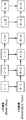
- FIG. 3 is a block diagram showing a configuration of multi-view video decoding apparatus 100 according to Embodiment 1 of the present invention.
- the multi-view video decoding device 100 is a device that decodes a plurality of encoded video images obtained by encoding a plurality of video images from a plurality of viewpoints. Specifically, the multi-view video decoding device 100 is a device that decodes a plurality of moving image coded streams that are multi-view coded and have a reference relationship. As shown in the figure, the multi-view video decoding device 100 includes a decoding unit 110, an error detection unit 120, a decoded image change unit 130, and a buffer 140.
- the buffer 140 is a memory that stores the decoded image.
- the buffer 140 includes a decoded image buffer L141 and a decoded image buffer R142.
- the decoded image buffer L141 stores an L image that is a decoded image for the left eye.
- the decoded image buffer R142 stores an R image that is a decoded image for the right eye.
- the decoding unit 110 decodes one encoded moving image of the plurality of encoded moving images without referring to the decoded image of the other encoded moving image, and one decoded moving image including the plurality of decoded images. An image is generated, and another decoded moving image is generated by decoding the other encoded moving image with reference to the decoded image included in the one decoded moving image.
- the decoding unit 110 is the one encoding that is an encoded moving image for the left eye among two encoded moving images in which moving images from the viewpoint for the left eye and the viewpoint for the right eye are encoded.
- the moving image is decoded to generate the one decoded moving image
- the other encoded moving image that is the encoded moving image for the right eye is decoded to generate the other decoded moving image.
- the decoding unit 110 refers to the base video encoded stream of the Base View side channel of the two channel video encoded streams, and refers to the decoded video of the R video encoded stream of the Dependent View side channel.
- an L image composed of a plurality of decoded images is generated, and an R image is generated by decoding an R moving image encoded stream with reference to the decoded image included in the L image.
- the decoding unit 110 decodes the multi-channel moving image encoded stream input to the decoding unit 110 and outputs a decoded image.
- the decoding unit 110 stores the output decoded image in the buffer 140. That is, the decoding unit 110 separately stores the L image in the decoded image buffer L141 and the R image in the decoded image buffer R142.
- the decoding unit 110 performs inter-screen coding such as P picture and B picture, and when it is necessary to refer to the decoded image at the time of decoding, the decoding unit 110 stores the decoded image in these decoded image buffer L141 and decoded image buffer R142. Refer to the decoded image. As shown in FIG. 3, an arrow from the decoded image buffer L141 or the decoded image buffer R142 to the decoding unit 110 indicates acquisition of this reference image.
- each of the decoded image buffer L141 and the decoded image buffer R142 can store not only one image but also a plurality of decoded images.
- the buffer 140 may be configured with an external memory or may be configured with a built-in memory. Further, the decoded image buffer L141 and the decoded image buffer R142 may be physically on the same memory, or may be configured by different memories.
- the error detection unit 120 detects an error image that is a decoded image including an error from a plurality of decoded images included in one decoded moving image or another decoded moving image. That is, the error detection unit 120 detects an error image from a plurality of decoded images included in the L image or the R image.
- the error detection unit 120 detects an error image by detecting an error included in the input moving image encoded stream from the decoding result of the decoding unit 110.
- the error detection unit 120 is not limited to detecting an error image from the decoding result of the decoding unit 110, and may detect an error image by detecting an error from the input moving image encoded stream. .
- an error is an error such as inversion, omission, mixing, etc. of a bit included in a moving image encoded stream, or an error of a syntax (a rule indicating a setting rule such as an order of image information or an encoded data string).
- Etc. That is, an error is when a moving image encoded stream is input from an optical disk or a hard disk, transmitted via wireless, or distributed in a streaming manner, until the moving image encoded stream reaches the decoding unit 110. This indicates that the decoding unit 110 cannot output a decoded image correctly due to bit inversion, omission, mixing, and the like.
- the decoded image changing unit 130 changes the error image detected by the error detection unit 120 to a first decoded image that does not include an error, and a decoded moving image other than the first decoded moving image that is a decoded moving image including the error image.
- the corresponding error image that is a decoded image that is included in the second decoded moving image that is an image and is displayed corresponding to the error image is changed to the second decoded image.
- the decoded image changing unit 130 uses a past image that is a decoded image included in the first decoded moving image decoded in the past from the error image without using the second decoded moving image.
- the corresponding decoded image is a decoded image that is included in the second decoded moving image and displayed corresponding to the past image without using the first decoded moving image. It changes to the 2nd decoding image produced
- the past image is an image that is displayed immediately before the error image and does not include an error.
- the error image and the corresponding error image are images displayed at the same time, and the past image and the corresponding past image are images displayed at the same time.
- the decoded image changing unit 130 changes the past image as the first decoded image, the error image as the first decoded image, the corresponding past image as the second decoded image, and the corresponding error image as the second decoded image. Change to an image.
- the decoded image changing unit 130 is an error decoded image that is a plurality of decoded images that are included in the first decoded moving image and displayed from the error image to the decoded image displayed corresponding to the immediately preceding image or the immediately preceding image. Is changed using the past image, and the corresponding error decoded image which is a plurality of decoded images included in the second decoded moving image and displayed corresponding to the error decoded image is changed using the corresponding past image.
- the immediately preceding image is a decoded image immediately before the decoded image obtained by decoding the intra-screen encoded image included in the encoded moving image before decoding of one decoded moving image.
- the immediately preceding image is encoded in the screen when the decoded image obtained by decoding the encoded image in the screen and the decoded image displayed corresponding to the decoded image do not include an error. It is a decoded image immediately before the decoded image obtained by decoding the image.
- the decoded image changing unit 130 changes the error decoded image so that the plurality of decoded images included in the error decoded image are the same as the first decoded image generated using the past image, and the corresponding error The corresponding error decoded image is changed so that a plurality of decoded images included in the decoded image are the same as the second decoded image generated using the corresponding past image.
- the decoded image changing unit 130 displays the L image stored in the decoded image buffer L141 and the R image stored in the decoded image buffer R142.
- the output image L and the output image R are output.
- the output image L and the output image R are an output image for the L channel and an output image for the R channel, respectively.
- the output image may be output immediately after decoding, or there may be some decoded images that are referred to after being decoded.
- This output timing is determined according to the ITU-T recommendation H.264. H.264, MPEG (Motion Picture Cording Expert Group; ISO 11172 (MPEG1), ISO 13818 (MPEG2)) and the like.
- the output timing and the like are recorded in the moving image encoded stream, and the output image is output in the output order and the output timing according to these.
- the output image is output immediately after decoding, but this is not restrictive.
- the output image L and the output image R may be directly output to an external display device, or may be displayed after being stored in another memory and then subjected to high image quality processing such as an image filter. It may be output to the device.
- the decoded image change unit 130 outputs an output image so as to repair the error image.
- the decoding unit 110 may determine that decoding is not possible and may stop the decoding operation.
- the decoding unit 110 notifies the error detection unit 120 that an error has been detected.
- the error detection unit 120 Upon receiving the error notification, the error detection unit 120 outputs a command for repairing the error image to the decoded image change unit 130.
- the decoded image changing unit 130 instructs the output image L for the L channel to output the previously decoded L image stored in the decoded image buffer L141. Further, the decoded image changing unit 130 instructs the output image R for the other R channel to output the previously decoded R image stored in the decoded image buffer R142.
- L image and R image indicate images corresponding to the same display time in the output order recorded in the stream.
- L image and R image corresponding to the same numerical positions shown in FIG. 15 are shown, and correspond to the same display order for L and R.
- the output image L corresponds to the “first decoded image” described in the claims
- the output image R corresponds to the “second decoded image” described in the claims.
- the L image that has been decoded in the past corresponds to the “past image” described in the claims
- the R image that has been decoded in the past corresponds to the “corresponding past image” described in the claims. .
- the decoding unit 110 may determine that decoding is not possible and may stop the decoding operation.
- the decoding unit 110 notifies the error detection unit 120 that an error has been detected.
- the error detection unit 120 Upon receiving the error notification, the error detection unit 120 outputs a command for repairing the error image to the decoded image change unit 130.
- the decoded image changing unit 130 instructs the output image R for the R channel to output the previously decoded R image stored in the decoded image buffer R142. Also, the decoded image changing unit 130 instructs the output image L for the other L channel to output the previously decoded L image stored in the decoded image buffer L141.
- the output image R corresponds to the “first decoded image” recited in the claims
- the output image L corresponds to the “second decoded image” recited in the claims.
- the R image that has been decoded in the past corresponds to the “past image” described in the claims
- the L image that has been decoded in the past corresponds to the “corresponding past image” described in the claims. .
- the decoding unit 110 may determine that decoding is not possible and may stop the decoding operation.
- the decoding unit 110 notifies the error detection unit 120 that an error has been detected.
- the error detection unit 120 Upon receiving the error notification, the error detection unit 120 outputs a command for repairing the error image to the decoded image change unit 130.
- the decoded image changing unit 130 that has received a command to repair the error image, for the L channel output image L and the R channel output image R, has been stored in the decoded image buffer L141 in the past and has been decoded for L. An instruction is given to output the image and each of the previously decoded R images stored in the decoded image buffer R142.
- the output image L corresponds to one of the “first decoded image” or the “second decoded image” described in the claims
- the output image R is the “first decoding image” described in the claims. It corresponds to the other of “image” or “second decoded image”.
- the previously decoded L image corresponds to one of the “past image” or the “corresponding past image” described in the claims
- the previously decoded R image is described in the claims. It corresponds to the other of “past image” or “corresponding past image”.
- FIG. 4 is a flowchart showing a decoding process performed by the multi-view video decoding device 100 according to Embodiment 1 of the present invention.
- a multi-channel moving image encoded stream that is a plurality of encoded moving images is input to the decoding unit 110 (S102).
- the decoding unit 110 decodes a plurality of encoded moving images to generate a plurality of decoded moving images (S104).
- the error detection unit 120 determines the detection of an error image from among a plurality of decoded images included in the decoded moving image on the L channel side (S106).
- the error detection unit 120 When the error detection unit 120 does not detect an error image from the decoded moving image on the L channel side (NO in S106), the error detection unit 120 detects an error image from a plurality of decoded images included in the decoded moving image on the R channel side. Is determined (S108).
- the error detection unit 120 detects an error image from the decoded video on the L channel side (YES in S106), or detects an error image from the decoded video on the R channel side (YES in S108), the decoded image is changed.
- the unit 130 changes and outputs the error image and the corresponding error image to the past image and the corresponding past image on both the L channel side and the R channel side (S110).
- the decoded image changing unit 130 determines error detection on the L channel side or the R channel side based on the error detection information from the error detecting unit 120, and outputs the L channel as the output image L and the output image R. Both the side and the R channel side are instructed to output from the decoded image buffer L141 and the decoded image buffer R142 images having the same display time that have been decoded in the past.
- the same process (S110) is performed when an error is detected on both the L channel side and the R channel side.
- the decoding unit 110 determines whether or not the image of the moving image encoded stream on the next L channel side is an image composed of an intra-screen encoded image, and the L channel side and the R channel from the error detection unit 120. It is determined whether or not an error is detected in the image of the moving image encoded stream on the side and decoding is possible (S112).
- the decoded image change unit 130 outputs the decoded image from the decoded image buffer L141 and the decoded image buffer R142 (S116).
- the decoding unit 110 determines that the L channel side is not configured with an intra-screen encoded image, or an error is included in the L channel side or the R channel side (NO in S112), the L channel and the R channel On both sides, the next image is changed to a past image and a corresponding past image and output (S114).
- the decoding unit 110 performs decoding after the decoding of the desired image on both the L channel and R channel sides.
- the image changing unit 130 outputs the decoded image from the decoded image buffer L141 and the decoded image buffer R142 (S116).
- the in-screen encoded image is H.264. It may be an H.264 IDR picture (instantaneous decoding update picture, Instantaneous Decoding Refresh Picture).
- the IDR picture is the first picture in the image sequence.
- the reference picture existing in the decoded image buffer L141 and the decoded image buffer R142 before the IDR picture is made unreferenceable, and there is no error on both the L channel side and the R channel side. For example, the possibility that an error will be mixed after this IDR picture is reduced. For this reason, when the intra-picture encoded image is an IDR picture, the subsequent image does not refer to an image decoded temporally before the IDR picture, and error mixing can be reliably reduced.
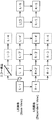
- 5 to 7 are diagrams showing output images output by the multi-view video decoding device 100 according to the first embodiment.
- the upper row represents the left eye L channel output image (L image), and the lower row represents the right eye R channel output image (R image).
- L-1 to L-6 represent output images decoded from the L channel side moving image encoded stream, and R-1 to R-6 are decoded from the R channel side moving image encoded stream. Represents the output image. Further, the lower the number, the earlier the output image in time.
- L-5 underlined in the image name represents an output image decoded from the encoded data encoded in the screen, and other images are decoded from the encoded data encoded in the inter-screen. Indicates that the output image has been output.
- the arrow indicates that the original image of the arrow is referred to in order to decode the image ahead of the arrow during the inter-picture encoding. For example, it indicates that L-1 is referenced to decode R-1.
- the error detection unit 120 detects the error image L-2 as a decoding error on the L channel side (YES in S106 in FIG. 4). That is, the fact that the decoded image changing unit 130 outputs the previously decoded image L-1 instead of L-2 in the figure is indicated by a thick white arrow in the figure. It also shows that the decoded image changing unit 130 outputs an image R-1 that has been decoded in the past and corresponds to the same display time as the L channel instead of R-2. This indicates that when the error detection unit 120 detects an error image, the decoded image change unit 130 does not output an error image mixed with an error.
- the decoded image changing unit 130 continues to output the L-1 and R-1 images when the next moving image encoded stream on the L channel side is not an intra-screen encoded image (NO in S112 in FIG. 4).
- S114 when the L channel side moving image encoded stream is an intra-screen encoded image and no error is detected on both the L channel side and the R channel side, normal images on both the L channel side and the R channel side Is output (YES in S112 of FIG. 4, S116).
- the L image corresponds to “one decoded moving image” and “first decoded moving image” recited in the claims.
- the R image corresponds to “another decoded moving image” and “second decoded moving image” recited in the claims.
- L-2 and R-2 correspond to “error image” and “corresponding error image” described in the claims, respectively.
- L-1 and R-1 correspond to “past image” and “corresponding past image” described in the claims, respectively.
- L-4 corresponds to the “immediately preceding image” described in the claims
- the plurality of decoded images from L-2 to L-4 correspond to the “error decoded images” described in the claims.
- the plurality of decoded images from R-2 to R-4 correspond to “corresponding error decoded images” described in the claims.
- L-2 which is the first image of, is called an error image.
- FIG. 6 shows an output image as in FIG. Since the description of FIG. 6 is the same as that of FIG. 5, detailed description thereof is omitted.
- the error image is repaired according to the process shown in FIG. 4 (S108 to S116 in FIG. 4). .
- the error detection unit 120 detects the error image R-2 as a decoding error on the R channel side (YES in S108 in FIG. 4). That is, the fact that the decoded image changing unit 130 outputs a previously decoded image R-1 instead of R-2 in FIG. 6 is indicated by a thick white arrow in the figure. It also shows that the decoded image changing unit 130 outputs an image L-1 that has been decoded in the past and has the same display time as the R channel instead of L-2. This indicates that when the error detection unit 120 detects an error image, the decoded image change unit 130 does not output an error image mixed with an error.
- the decoded image changing unit 130 continues to output the images of L-1 and R-1 when the moving image encoded stream on the L channel side to be input next is not an intra-screen encoded image (see FIG. NO in S112 of S4, S114), when the L channel side moving image encoded stream is an intra-screen encoded image and no error is detected when decoding the L channel side and R channel side encoded images, Normal images are output on both the L channel side and the R channel side (YES in S112 in FIG. 4, S116).
- the L image corresponds to “one decoded moving image” and “second decoded moving image” recited in the claims.
- the R image corresponds to “another decoded moving image” and “first decoded moving image” recited in the claims.
- R-2 and L-2 correspond to “error image” and “corresponding error image” described in the claims, respectively.
- R-1 and L-1 correspond to “past image” and “corresponding past image” described in the claims, respectively.
- L-4 corresponds to the “immediately preceding image” described in the claims
- the plurality of decoded images from R-2 to R-4 correspond to the “error decoded images” described in the claims.
- the plurality of decoded images from L-2 to L-4 correspond to “corresponding error decoded images” described in the claims.
- R-2 which is the first image, is called an error image.
- the error detection unit 120 detects a decoding error on the L channel side and the R channel side. That is, the decoded image changing unit 130 outputs the previously decoded images L-1 and R-1 instead of L-2 and R-2 in FIG. It shows with. This indicates that when the error detection unit 120 detects an error image, the decoded image change unit 130 does not output an error image mixed with an error.
- the decoded image changing unit 130 continues to output the L-1 and R-1 images when the L channel side moving image encoded stream to be input next is not an intra-screen encoded image. If the video encoding stream on the side is an intra-picture encoded image and no error is detected when decoding the L channel side and R channel side encoded images, both the L channel side and the R channel side are normal images. Is output.
- L-2 is an error image
- R-2 is an error image
- L-2 and R-2 correspond to the “error image” and “corresponding error image” described in the claims, respectively, L-1 and R-1 are respectively described in the claims. It corresponds to “past image” and “corresponding past image”.
- L-4 corresponds to the “immediately preceding image” described in the claims, and the plurality of decoded images from L-2 to L-4 correspond to the “error decoded images” described in the claims. .
- the plurality of decoded images from R-2 to R-4 correspond to “corresponding error decoded images” described in the claims.
- the L image corresponds to “one decoded moving image” and “first decoded moving image” recited in the claims.
- the R image corresponds to “another decoded moving image” and “second decoded moving image” recited in the claims.
- R-2 and L-2 correspond to the “error image” and “corresponding error image” described in the claims, respectively, R-1 and L-1 are respectively described in the claims. It corresponds to “past image” and “corresponding past image”.
- L-4 corresponds to the “previous image” described in the claims, and the plurality of decoded images from R-2 to R-4 correspond to the “error decoded images” described in the claims. .
- the plurality of decoded images from L-2 to L-4 correspond to “corresponding error decoded images” described in the claims.
- the L image corresponds to “one decoded moving image” and “second decoded moving image” recited in the claims.
- the R image corresponds to “another decoded moving image” and “first decoded moving image” recited in the claims.
- the number of channels on the Dependent View side of the input moving image encoded stream is one channel.
- the number of channels on the Dependent View side of the input moving image encoded stream is two channels.
- FIG. 8 is a block diagram showing a configuration of multi-view video decoding apparatus 100 according to Embodiment 2 of the present invention.
- the multi-view video decoding device 100 is the same as the multi-view video decoding device 100 according to the first embodiment, and includes a decoding unit 110, an error detection unit 120, and a decoded image change. Unit 130 and buffer 140.
- the multi-view video decoding device 100 receives a three-channel moving image encoded stream that is three encoded moving images.
- the buffer 140 is a memory that stores a decoded image, and includes a decoded image buffer L141, a decoded image buffer R 1 142, and a decoded image buffer R 2 143.
- the decoded image buffer L141 stores an L image that is a decoded image of the Base View side channel.
- the decoded image buffer R 1 142 and the decoded image buffer R 2 143 store an image for R1 and an image for R2 that are decoded images of two dependent view side channels, respectively.
- the decoding unit 110 decodes one encoded moving image out of the three encoded moving images without referring to the decoded images of the other two encoded moving images to generate one decoded moving image. At the same time, referring to the decoded image included in the one decoded moving image, the other two encoded moving images are decoded to generate the other two decoded moving images.
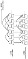
- FIG. 9 is a diagram illustrating a process in which the decoding unit 110 according to the second embodiment decodes three encoded moving images.
- the description method of arrows and the like shown in the figure is the same as the description method described with reference to FIG.
- the decoding unit 110 is a decoded image of an encoded video stream for L of the Base View side channel, an encoded video stream for R1 and an encoded video stream for R2 of two dependent view side channels. Decoding is performed without referring to the R1 image and the R2 image, and an L image composed of a plurality of decoded images is generated.
- the decoding unit 110 decodes the R1 moving image encoded stream and the R2 moving image encoded stream to generate an R1 image and an R2 image.
- the decoding unit 110 refers to the decoded image included in the L image, and generates the R1 image.
- the decoding unit 110 generates an R2 image with reference to the decoded image included in the L image or the R1 image.
- the decoded image corresponding to the same display time is referred to.
- the error detection unit 120 detects an error image from among a plurality of decoded images included in the L image, the R1 image, or the R2 image.
- the decoded image changing unit 130 changes the error image detected by the error detecting unit 120 to the first decoded image generated using the past image, and the corresponding error image is generated using the corresponding past image. Change to decoded image.
- the decoded image changing unit 130 changes the error decoded image displayed from the error image to the decoded image displayed corresponding to the previous image or the previous image using the past image, and changes the corresponding error decoded image. , Change using the corresponding past image.
- the decoded image change unit 130 decodes the output image L for the L channel in the past stored in the decoded image buffer L141. Instructs to output a completed L image.
- the decoded image changing unit 130 has also decoded the output image R1 for the other R1 channel and the output image R2 for the R2 channel in the past stored in the decoded image buffer R 1 142 and the decoded image buffer R 2 143. To output the R1 image and the R2 image.
- the output image L corresponds to the “first decoded image” described in the claims
- the output image R1 and the output image R2 correspond to the “second decoded image” described in the claims.
- the previously decoded L image corresponds to the “past image” described in the claims
- the previously decoded R1 image and R2 image are the “corresponding past images” described in the claims. Is equivalent to.
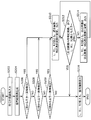
- FIG. 10 is a flowchart showing a decoding process performed by the multi-view video decoding device 100 according to the second embodiment.
- a 3-channel moving image encoded stream which is a plurality of encoded moving images, is input to the decoding unit 110 (S202).
- the decoding unit 110 decodes a plurality of encoded moving images to generate a plurality of decoded moving images (S204).
- the error detection unit 120 determines the detection of an error image from among a plurality of decoded images included in the decoded video on the L channel side (S206).
- the error detection unit 120 detects an error image from a plurality of decoded images included in the decoded video on the R1 channel side. Is determined (S208).
- the error detection unit 120 detects an error image from among a plurality of decoded images included in the decoded moving image on the R2 channel side. Is determined (S209).
- the decoded image changing unit 130 converts the error image and the corresponding error image into the past image and the corresponding past on both the L channel side, the R1 channel side, and the R2 channel side. The image is changed and output (S210).
- the decoded image changing unit 130 outputs, as the output image L, the output image R1, and the output image R2, images of the same display time that have been decoded in the past on the L channel side, R1 channel side, and R2 channel side, Instructions are output from the decoded image buffer L141, decoded image buffer R 1 142, and decoded image buffer R 2 143.
- the same process (S210) is performed when an error is detected in two or more channels among the L channel side, the R1 channel side, and the R2 channel side.
- the decoding unit 110 determines whether or not the image of the next L channel side moving image encoded stream is an image composed of an intra-screen encoded image, and from the error detection unit 120 to the L channel side, the R1 channel It is determined whether or not an error is detected in the video of the moving image encoded stream on the side and the R2 channel side and decoding is possible (S212).
- the decoded image change unit 130 receives decoded images from the decoded image buffer L141, the decoded image buffer R 1 142, and the decoded image buffer R 2 143. It outputs (S216).
- the decoding unit 110 determines that the L channel side is not configured with an intra-screen encoded image, or an error is included in the L channel side, the R1 channel side, or the R2 channel side (NO in S212), L On the channel side, the R1 channel side, and the R2 channel side, the next image is changed to a past image and a corresponding past image and output (S214).
- the L channel side, the R1 channel side, and the R2 channel side are all the following until the L channel side is composed of an intra-coded image and there are no errors on the L channel side, the R1 channel side, and the R2 channel side.
- the process of changing the image into a past image and a corresponding past image and outputting it (S214) is repeated. Note that the processing may be completed at the end of the moving image encoded stream input, but this is not shown.
- the decoding unit 110 determines whether the desired image is on the L channel side, the R1 channel side, and the R2 channel side. After completion of decoding, the decoded image changing unit 130 outputs decoded images from the decoded image buffer L141, the decoded image buffer R 1 142, and the decoded image buffer R 2 143 (S216).
- the in-screen encoded image may be an IDR picture.
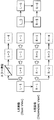
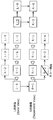
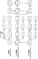
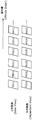
- 11 and 12 are diagrams showing output images output from the multi-view video decoding device 100 according to the second embodiment.
- the upper row represents the L channel output image (L image)
- the middle row represents the R1 channel output image (R1 image)
- the lower row represents the R2 channel output image (R2 image). Details are the same as those described with reference to FIGS.
- the error detection unit 120 detects the error image L-2 as a decoding error on the L channel side (YES in S206 in FIG. 10). That is, the fact that the decoded image changing unit 130 outputs the previously decoded image L-1 instead of L-2 in the figure is indicated by a thick white arrow in the figure. It also shows that the decoded image changing unit 130 outputs images R1-1 and R2-1 that have been decoded in the past and correspond to the same display time as the L channel instead of R1-2 and R2-2. . This indicates that when the error detection unit 120 detects an error image, the decoded image change unit 130 does not output an error image mixed with an error.
- the decoded image changing unit 130 continues to output the images of L-1, R1-1, and R2-1 when the next L channel side moving image encoded stream is not an intra-screen encoded image (S212 in FIG. 10). NO, S214), when the video encoded stream on the L channel side is an intra-picture encoded image, and no error is detected on the L channel side, the R1 channel side, and the R2 channel side, the L channel side, Normal images are output on both the R1 channel side and the R2 channel side (YES in S212 of FIG. 10, S216).
- the L image corresponds to “one decoded moving image” and “first decoded moving image” recited in the claims.
- the R1 image and the R2 image correspond to “another decoded moving image” and “second decoded moving image” recited in the claims.
- L-2 corresponds to the “error image” described in the claims
- R1-2 and R2-2 correspond to the “corresponding error image” described in the claims
- L-1 corresponds to a “past image” described in the claims
- R1-1 and R2-1 correspond to a “corresponding past image” described in the claims.
- L-4 corresponds to the “immediately preceding image” described in the claims
- the plurality of decoded images from L-2 to L-4 correspond to the “error decoded images” described in the claims.
- the plurality of decoded images from R1-2 to R1-4 and the plurality of decoded images from R2-2 to R2-4 correspond to “corresponding error decoded images” described in the claims.
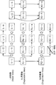
- the error detection unit 120 detects the error image R2-2 as a decoding error on the R2 channel side (YES in S209 of FIG. 10). That is, the fact that the decoded image changing unit 130 outputs a previously decoded image R2-1 instead of R2-2 in the figure is indicated by a thick white arrow in the figure. It also shows that the decoded image changing unit 130 outputs images L-1 and R1-1 that have been decoded in the past and correspond to the same display time as the R2 channel side, instead of L-2 and R1-2. . This indicates that when the error detection unit 120 detects an error image, the decoded image change unit 130 does not output an error image mixed with an error.
- the decoded image changing unit 130 continues to output the images of L-1, R1-1, and R2-1 when the next L channel side moving image encoded stream is not an intra-screen encoded image (S212 in FIG. 10). NO, S214), when the video encoded stream on the L channel side is an intra-picture encoded image, and no error is detected on the L channel side, the R1 channel side, and the R2 channel side, the L channel side, Normal images are output on both the R1 channel side and the R2 channel side (YES in S212 of FIG. 10, S216).
- the L image corresponds to “one decoded moving image” and “second decoded moving image” recited in the claims.
- the R1 image corresponds to “another decoded moving image” and “second decoded moving image” recited in the claims.
- the R2 image corresponds to “another decoded moving image” and “first decoded moving image” recited in the claims.
- R2-2 corresponds to the “error image” described in the claims
- L-2 and R1-2 correspond to the “corresponding error image” described in the claims
- R2-1 corresponds to the “past image” described in the claims
- L-1 and R1-1 correspond to the “corresponding past image” described in the claims.
- L-4 corresponds to the “previous image” described in the claims
- the plurality of decoded images from R2-2 to R2-4 correspond to the “error decoded images” described in the claims.
- the plurality of decoded images from L-2 to L-4 and the plurality of decoded images from R1-2 to R1-4 correspond to “corresponding error decoded images” described in the claims.
- the error when an error is detected in R1-2 decoded from the video encoded stream on the R1 channel side, the error can be repaired by performing the same processing.
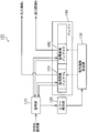
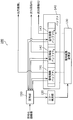
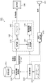
- FIG. 13 is a block diagram showing a configuration of multi-view video decoding apparatus 200 according to the third embodiment.
- FIG. 3 shows a configuration applicable to a DVD recorder (digital video recorder), a Blu-ray disc recorder (Blu-ray Disk Recorder, BD recorder), etc., based on FIG. 3 showing the first embodiment.
- DVD recorder digital video recorder
- Blu-ray disc recorder Blu-ray Disk Recorder
- BD recorder Blu-ray Disk Recorder
- the multi-view video decoding device 200 includes a storage device 151, a storage device control unit 150, an overall control unit 160, a user interface 161, a voice decoding unit 170, and a display unit. 180 and a speaker 190 are provided.
- the storage device control unit 150 reads out a multi-view video encoded stream, which is an encoded moving image stored in the storage device 151, based on an instruction from the overall control unit 160, and sends it to the decoding unit 110.
- the decoding unit 110 decodes the sent multi-view video encoded stream and stores it in the buffer 140.
- the error detection unit 120 detects whether or not there is an error in the above-described multi-view video encoded stream, and sends the error information to the decoded image change unit 130 as in FIG.
- the decoded image changing unit 130 selects an output image from the buffer 140 and outputs it to the display unit 180.
- the multi-view video encoded stream is composed of L channel and R channel video encoded streams
- 3D display is possible.
- the same processing as in the first embodiment can be performed.
- the storage device control unit 150 reads out the speech encoded data stored in the storage device 151 based on an instruction from the overall control unit 160 and sends it to the speech decoding unit 170.
- the audio encoded data is decoded by the audio decoding unit 170 and then output to the speaker 190.
- multi-view video decoding device 100 and the audio decoding unit 170 can be controlled from the overall control unit 160 via the user interface 161.
- an error image is detected from a plurality of decoded images included in a plurality of decoded video images, and an error image is detected. And the corresponding error image are changed to an image including no error by using the past image and the corresponding past image. For this reason, even if an error is included in any of the plurality of input encoded moving images, an error-free image can be output.
- the error decoded image displayed from the error image to the decoded image immediately before the decoded image obtained by decoding the intra-coded image is changed using the past image, and the corresponding error decoded image is changed to the corresponding past image.
- the intra-coded image is not decoded with reference to other images, there is a low possibility that an error is mixed, and the error is also mixed in the images after the intra-coded image. Less likely.
- the error decoded image and the corresponding error decoded image may be changed using the IDR picture as the intra-coded image. That is, after an error has occurred, the error is repaired until an IDR picture appears in the motion video encoded stream on the Base View side.
- the IDR picture is a head picture of an image sequence, and is a picture in which all information for decoding is reset. For this reason, the IDR picture is unlikely to contain an error in the intra-picture encoded image, and the possibility that an error is also mixed in the image after the IDR picture is low.
- both the decoded image obtained by decoding the intra-screen encoded image and the decoded image displayed corresponding to the decoded image are images that do not include an error
- the error decoded image and the corresponding error decoded image are displayed. change. For this reason, by repairing the error while the error is included, there is little possibility that the recognition of the content of the image will be hindered, and the influence on human vision can be reduced as much as possible.
- a plurality of decoded images included in the error decoded image are changed so that the image is the same as the image generated using the past image so that the image is the same as the image generated using the corresponding past image.
- the plurality of decoded images included in the corresponding error decoded image are changed. That is, by changing a plurality of decoded images to the same image and repairing the error, it is possible to eliminate a sense of incongruity such as a sudden display of different images.
- the error image and the corresponding error image are images displayed at the same time, and are changed using the past image and the corresponding past image displayed at the same time. For this reason, for example, in a 3D image in which a right-eye image and a left-eye image are displayed at the same time, there is little risk of hindering recognition of the contents of the image, and the influence on human vision is minimized. it can.
- the multi-view video decoding device 100 has been described above, but the present invention is not limited to these embodiments. Unless it deviates from the meaning of this invention, the form which carried out the various deformation
- the number of channels on the dependent view side of the input moving image encoded stream is one channel or two channels.
- the number of channels on the dependent view side of the moving image encoded stream is not limited to one channel or two channels, and may be three or more channels.
- the predetermined decoded image and the decoded image displayed corresponding to the decoded image are output at the same time, such as the left-eye L image and the right-eye R image.
- the plurality of correspondingly displayed decoded images are not limited to being displayed at the same time, and may be displayed alternately. For example, even if the L image and the R image are alternately displayed, the user can view the 3D video.
- the multi-view video decoding device 100 includes the single decoding unit 110.
- the multi-view video decoding device 100 may include a plurality of decoding units 110.
- the past image is an image that is displayed immediately before the error image and does not include an error.
- the past image is not limited to an image displayed immediately before the error image, and may be an image displayed two times before the error image, for example.
- the decoded image changing unit 130 changes the error image to the same image as the past image, and changes the corresponding error image to the same image as the corresponding past image.
- the decoded image changing unit 130 changes the error image to an image that is not exactly the same as the past image, but is transformed from the past image, and the corresponding error image is not exactly the same as the corresponding past image, but corresponds to the corresponding past image.
- the image may be changed to a deformed image.
- the decoded image changing unit 130 changes the decoded image up to the image immediately before the decoded image obtained by decoding the intra-screen encoded image.
- the decoded image changing unit 130 may change the decoded image by a predetermined number, for example, without going to the previous image.
- the decoded image changing unit 130 changes the decoded image until no error is included in the decoded image.
- the decoded image changing unit 130 may change the decoded image up to the previous image or a predetermined number without determining whether the decoded image includes an error.
- the decoded image changing unit 130 changes the error decoded image so that the plurality of decoded images included in the error decoded image are the same as the past image, and is included in the corresponding error decoded image.
- the corresponding error decoded image is changed so that a plurality of decoded images become the same image as the corresponding past image.
- the decoded image changing unit 130 changes a plurality of decoded images included in the error decoded image to an image that is not the same image as the past image, but is transformed from the past image, and a plurality of decoded images included in the corresponding error decoded image.
- the image may not be exactly the same as the corresponding past image, but may be changed to an image deformed from the corresponding past image. Also, the plurality of decoded images included in the error decoded image need not all be the same image, and the plurality of decoded images included in the corresponding error decoded image need not all be the same image.
- the multi-view video decoding device 100 according to the present invention is applied to a DVD recorder or a Blu-ray disc recorder.
- the multi-view video decoding device 100 according to the present invention is not limited to a DVD.
- the present invention can be applied to a three-dimensional image display device (for example, a DVD player, a Blu-ray disc player, a digital TV, a mobile phone device, a personal computer, etc.) that displays a three-dimensional image other than a recorder or a Blu-ray disc recorder.
- the multi-view video decoding device 100 is typically realized as an LSI that is an integrated circuit. These may be individually made into one chip, or may be made into one chip so as to include a part or all of them.
- the decoding unit 110, the error detection unit 120, and the decoded image change unit 130 may be individually made into one chip. , It may be integrated into one chip so as to include some or all of them.
- circuits are not limited to LSI, and may be realized by a dedicated circuit or a general-purpose processor.
- An FPGA Field Programmable Gate Array
- reconfigurable processor that can reconfigure the connection and setting of circuit cells inside the LSI may be used.
- some or all of the functions of the multi-view video decoding apparatus 100 according to Embodiments 1 and 2 may be realized by a processor such as a CPU executing a program.
- the present invention may be the above program or a recording medium on which the above program is recorded.
- the program can be distributed via a transmission medium such as the Internet.
- the multi-view video decoding apparatus is useful for a multi-view video decoding apparatus that decodes a plurality of moving image encoded streams that are multi-view encoded and have a reference relationship, and a playback method thereof.
- the present invention can also be applied to uses such as a DVD recorder, a DVD player, a Blu-ray disc recorder, a Blu-ray disc player, and a TV capable of outputting data for 3D display.
- Multiview Video Decoding Device 110 Decoding Unit 120 Error Detection Unit 130 Decoded Image Changing Unit 140 Buffer 141 Decoded Image Buffer L 142 Decoded Image Buffer R (Decoded Image Buffer R 1 ) 143 Decoded image buffer R 2 150 Storage Device Control Unit 151 Storage Device 160 Overall Control Unit 161 User Interface 170 Audio Decoding Unit 180 Display Unit 190 Speaker 200 Multi-viewpoint Video Decoding Device (DVD Recorder, Blu-ray Disc Recorder) 1000 Multi-view Video Decoding Device 1010 Decoding Unit 1020 Error Detection Unit 1030 Output Image Determination Unit 1040 Buffer 1041 Decoded Image Buffer L 1042 Decoded image buffer R 1050 Error image restoration part L 1060 Error image restoration part R
Landscapes
- Engineering & Computer Science (AREA)
- Multimedia (AREA)
- Signal Processing (AREA)
- Compression Or Coding Systems Of Tv Signals (AREA)
- Testing, Inspecting, Measuring Of Stereoscopic Televisions And Televisions (AREA)
Priority Applications (2)
| Application Number | Priority Date | Filing Date | Title |
|---|---|---|---|
| CN201080009868.8A CN102342118B (zh) | 2009-12-15 | 2010-05-21 | 多视点动态图像解码装置以及多视点动态图像解码方法 |
| US13/196,444 US8750388B2 (en) | 2009-12-15 | 2011-08-02 | Multiview video decoding apparatus, multiview video decoding method, multiview video decoding program, and multiview video decoding integrated circuit |
Applications Claiming Priority (2)
| Application Number | Priority Date | Filing Date | Title |
|---|---|---|---|
| JP2009284534A JP4837772B2 (ja) | 2009-12-15 | 2009-12-15 | 多視点動画像復号装置、多視点動画像復号方法、プログラム及び集積回路 |
| JP2009-284534 | 2009-12-15 |
Related Child Applications (1)
| Application Number | Title | Priority Date | Filing Date |
|---|---|---|---|
| US13/196,444 Continuation US8750388B2 (en) | 2009-12-15 | 2011-08-02 | Multiview video decoding apparatus, multiview video decoding method, multiview video decoding program, and multiview video decoding integrated circuit |
Publications (1)
| Publication Number | Publication Date |
|---|---|
| WO2011074148A1 true WO2011074148A1 (ja) | 2011-06-23 |
Family
ID=44166922
Family Applications (1)
| Application Number | Title | Priority Date | Filing Date |
|---|---|---|---|
| PCT/JP2010/003424 Ceased WO2011074148A1 (ja) | 2009-12-15 | 2010-05-21 | 多視点動画像復号装置、多視点動画像復号方法、プログラム及び集積回路 |
Country Status (4)
| Country | Link |
|---|---|
| US (1) | US8750388B2 (enExample) |
| JP (1) | JP4837772B2 (enExample) |
| CN (1) | CN102342118B (enExample) |
| WO (1) | WO2011074148A1 (enExample) |
Cited By (1)
| Publication number | Priority date | Publication date | Assignee | Title |
|---|---|---|---|---|
| WO2011162168A1 (ja) * | 2010-06-24 | 2011-12-29 | ソニー株式会社 | 情報処理装置および情報処理方法 |
Families Citing this family (10)
| Publication number | Priority date | Publication date | Assignee | Title |
|---|---|---|---|---|
| JP5614268B2 (ja) * | 2010-12-09 | 2014-10-29 | ソニー株式会社 | 画像処理装置、および画像処理方法、並びにプログラム |
| JP2013247651A (ja) * | 2012-05-29 | 2013-12-09 | Canon Inc | 符号化装置、符号化方法およびプログラム |
| WO2014015884A1 (de) * | 2012-07-25 | 2014-01-30 | Unify Gmbh & Co. Kg | Verfahren zur behandlung von störungen bei der übertragung einer zeitlichen folge digitaler bilder |
| US9066082B2 (en) * | 2013-03-15 | 2015-06-23 | International Business Machines Corporation | Forensics in multi-channel media content |
| JP6365924B2 (ja) * | 2013-05-09 | 2018-08-01 | サン パテント トラスト | 画像復号方法及び画像復号装置 |
| JP2015136060A (ja) * | 2014-01-17 | 2015-07-27 | ソニー株式会社 | 通信装置、通信データ生成方法、および通信データ処理方法 |
| FR3042368A1 (fr) * | 2015-10-08 | 2017-04-14 | Orange | Procede de codage et de decodage multi-vues, dispositif de codage et de decodage multi-vues et programmes d'ordinateur correspondants |
| KR20180021998A (ko) | 2016-08-23 | 2018-03-06 | 삼성전자주식회사 | 영상 수신을 위한 무선 수신 장치, 데이터 처리 모듈 및 그 방법 |
| US10614747B2 (en) * | 2017-01-31 | 2020-04-07 | Synaptics Incorporated | Device and method for driving display panel in response to image data |
| WO2020184316A1 (ja) * | 2019-03-13 | 2020-09-17 | ソニー株式会社 | 情報処理装置、情報処理方法、及びプログラム |
Citations (3)
| Publication number | Priority date | Publication date | Assignee | Title |
|---|---|---|---|---|
| JPH07322302A (ja) * | 1994-05-23 | 1995-12-08 | Sanyo Electric Co Ltd | 立体動画像再生装置 |
| JPH0847002A (ja) * | 1994-07-26 | 1996-02-16 | Sanyo Electric Co Ltd | 立体動画像の復号装置 |
| JP2003319419A (ja) * | 2002-04-25 | 2003-11-07 | Sharp Corp | データ復号装置 |
Family Cites Families (3)
| Publication number | Priority date | Publication date | Assignee | Title |
|---|---|---|---|---|
| US5767898A (en) * | 1994-06-23 | 1998-06-16 | Sanyo Electric Co., Ltd. | Three-dimensional image coding by merger of left and right images |
| EP1971154A4 (en) * | 2006-01-05 | 2010-10-27 | Nippon Telegraph & Telephone | VIDEO CODING METHOD AND DECODING METHOD, DEVICE THEREFOR, DEVICE THEREFOR AND STORAGE MEDIUM WITH THE PROGRAM |
| JP4793366B2 (ja) * | 2006-10-13 | 2011-10-12 | 日本ビクター株式会社 | 多視点画像符号化装置、多視点画像符号化方法、多視点画像符号化プログラム、多視点画像復号装置、多視点画像復号方法、及び多視点画像復号プログラム |
-
2009
- 2009-12-15 JP JP2009284534A patent/JP4837772B2/ja not_active Expired - Fee Related
-
2010
- 2010-05-21 WO PCT/JP2010/003424 patent/WO2011074148A1/ja not_active Ceased
- 2010-05-21 CN CN201080009868.8A patent/CN102342118B/zh not_active Expired - Fee Related
-
2011
- 2011-08-02 US US13/196,444 patent/US8750388B2/en not_active Expired - Fee Related
Patent Citations (3)
| Publication number | Priority date | Publication date | Assignee | Title |
|---|---|---|---|---|
| JPH07322302A (ja) * | 1994-05-23 | 1995-12-08 | Sanyo Electric Co Ltd | 立体動画像再生装置 |
| JPH0847002A (ja) * | 1994-07-26 | 1996-02-16 | Sanyo Electric Co Ltd | 立体動画像の復号装置 |
| JP2003319419A (ja) * | 2002-04-25 | 2003-11-07 | Sharp Corp | データ復号装置 |
Cited By (1)
| Publication number | Priority date | Publication date | Assignee | Title |
|---|---|---|---|---|
| WO2011162168A1 (ja) * | 2010-06-24 | 2011-12-29 | ソニー株式会社 | 情報処理装置および情報処理方法 |
Also Published As
| Publication number | Publication date |
|---|---|
| CN102342118B (zh) | 2014-08-13 |
| CN102342118A (zh) | 2012-02-01 |
| JP4837772B2 (ja) | 2011-12-14 |
| JP2011130029A (ja) | 2011-06-30 |
| US8750388B2 (en) | 2014-06-10 |
| US20110286531A1 (en) | 2011-11-24 |
Similar Documents
| Publication | Publication Date | Title |
|---|---|---|
| JP4837772B2 (ja) | 多視点動画像復号装置、多視点動画像復号方法、プログラム及び集積回路 | |
| CA2559131C (en) | Stereoscopic parameter embedding apparatus and stereoscopic image reproducer | |
| CN102342119B (zh) | 三维影像解码装置及三维影像解码方法 | |
| JP3992533B2 (ja) | 立体視を可能とする立体動画像用のデータ復号装置 | |
| RU2552137C2 (ru) | Точки входа для ускоренного 3d-воспроизведения | |
| JP3332575B2 (ja) | 立体動画像再生装置 | |
| JP5957769B2 (ja) | 映像処理装置及び映像処理方法 | |
| JPWO2012111325A1 (ja) | 映像符号化装置、映像符号化方法、映像符号化プログラム、映像再生装置、映像再生方法及び映像再生プログラム | |
| US12238321B2 (en) | Method for frame packing in a MPEG immersive video format | |
| JP5170708B2 (ja) | 動画像ストリーム加工方法及び装置、それを用いた動画像再生装置並びに動画像配信装置 | |
| KR101528269B1 (ko) | 동영상 재생 방법 | |
| TWI487379B (zh) | 視訊編碼方法、視訊編碼器、視訊解碼方法與視訊解碼器 | |
| JP5415217B2 (ja) | 三次元映像処理装置 | |
| JP4927928B2 (ja) | 多視点動画像復号装置及び多視点動画像復号方法 | |
| WO2013099571A1 (ja) | 視差調整装置、画像処理装置、フレームフォーマット | |
| US20140072271A1 (en) | Recording apparatus, recording method, reproduction apparatus, reproduction method, program, and recording reproduction apparatus | |
| JP6221820B2 (ja) | 符号化装置、符号化方法および符号化プログラム | |
| US20140078255A1 (en) | Reproduction device, reproduction method, and program | |
| KR101336820B1 (ko) | 다채널 트릭 모드에 특화된 복호화 장치 및 방법 | |
| US20140049608A1 (en) | Video processing device and video processing method | |
| KR101609798B1 (ko) | 동영상 판독 장치 | |
| JPH08149521A (ja) | 立体動画像の復号装置及び記録媒体 | |
| JPWO2000027132A1 (ja) | 映像信号の符号化/復号化 |
Legal Events
| Date | Code | Title | Description |
|---|---|---|---|
| WWE | Wipo information: entry into national phase |
Ref document number: 201080009868.8 Country of ref document: CN |
|
| 121 | Ep: the epo has been informed by wipo that ep was designated in this application |
Ref document number: 10837186 Country of ref document: EP Kind code of ref document: A1 |
|
| NENP | Non-entry into the national phase |
Ref country code: DE |
|
| 122 | Ep: pct application non-entry in european phase |
Ref document number: 10837186 Country of ref document: EP Kind code of ref document: A1 |