WO2011070677A1 - 情報処理装置及び制御方法 - Google Patents
情報処理装置及び制御方法 Download PDFInfo
- Publication number
- WO2011070677A1 WO2011070677A1 PCT/JP2009/070765 JP2009070765W WO2011070677A1 WO 2011070677 A1 WO2011070677 A1 WO 2011070677A1 JP 2009070765 W JP2009070765 W JP 2009070765W WO 2011070677 A1 WO2011070677 A1 WO 2011070677A1
- Authority
- WO
- WIPO (PCT)
- Prior art keywords
- information
- transmission request
- terminal device
- information transmission
- terminal
- Prior art date
- Legal status (The legal status is an assumption and is not a legal conclusion. Google has not performed a legal analysis and makes no representation as to the accuracy of the status listed.)
- Ceased
Links
Images



Classifications
-
- H—ELECTRICITY
- H04—ELECTRIC COMMUNICATION TECHNIQUE
- H04L—TRANSMISSION OF DIGITAL INFORMATION, e.g. TELEGRAPHIC COMMUNICATION
- H04L67/00—Network arrangements or protocols for supporting network services or applications
- H04L67/2866—Architectures; Arrangements
- H04L67/30—Profiles
- H04L67/303—Terminal profiles
Definitions
- This case relates to an information processing apparatus and a control method.
- the server device as the information processing device is connected to a client device as a terminal device that causes the server device to perform an original business, for example, a deposit / withdrawal processing business in a bank, and the server device performs the original business.
- a server apparatus is connected not only to a client apparatus that originally performs a task but also to a system control client apparatus as a system control terminal apparatus.
- the server device acquires device information including sensor states and the like of each unit in the server device and transmits the device information to the system control client device.
- the system control client displays the device information and is used for monitoring whether the server device is operating normally by an operator. Since the state of the server device changes from moment to moment, the system control client device makes a new request to the server device at regular intervals (for example, every 30 seconds), obtains new device information from the server device, and displays it. Update.
- a plurality of system control client devices may be connected to one server device.
- the load for collecting device information such as acquiring the state of the sensor of each part in the server device in response to a request from each of the plurality of client devices increases in the server device. If this load is to be suppressed, there will be inconveniences such as limiting the number of simultaneous connections of system control client devices.
- a terminal device as a plurality of client devices connected to a server device via a network as a communication path
- the event is a plurality of terminals.
- Techniques that are reflected in all of the devices have been proposed. This technique is intended to match the display formats of a plurality of terminal devices. Further, it has been proposed to display the same display information on a plurality of terminal devices at the same time by changing the display format.
- JP 2001-243165 A Japanese Patent Laid-Open No. 3-268048
- the problem with the information processing apparatus and control method disclosed herein is to reduce the load of collecting apparatus information.
- the information processing apparatus disclosed herein is an information processing apparatus connected to a plurality of terminal devices via a communication path.
- a communication unit that performs communication with a plurality of terminal devices;
- a device information acquisition unit for acquiring device information representing the state of the information processing device; 1st information transmission which has the information storage part which memorize
- Requesting acquisition receiving device information from the device information acquisition unit, storing the device information in the information storage unit, causing the communication unit to transmit the device information to the first terminal device, and among the plurality of terminal devices
- the communication unit receiving the first information transmission request transmitted by another terminal device other than the first terminal device, the first information transmission request stored in the information storage unit
- information transmission control unit that transmitted to the other terminal devices that has transmitted the first information transmission request, Is an information processing apparatus.
- the information storage unit that stores the acquired device information is provided, and the device information stored in the storage information unit is provided in the other terminal devices other than the first terminal device. To reduce the load of acquiring device information.
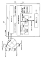
- FIG. 1 is a diagram showing a server apparatus as an information processing apparatus according to the first embodiment of the present case.
- the server device 100 is connected to a plurality (two in this case) of client devices 10A and 10B via the communication path 20.
- the communication path 20 is a network such as a LAN (Local Area Network).
- the number of client devices connected to the server device 100 is not limited to two, and may be three or more.
- the server device 100 includes a port 110 as a communication unit, an information transmission control unit 120, a device information acquisition unit 130, and a device H / W (hardware) 140.
- the device H / W 140 is shown as one block here, but is widely distributed in each part of the server device 140.
- a temperature sensor, a fan rotation speed sensor, a voltage sensor, a current sensor, and other various sensors are arranged. Is included.
- the information transmission control unit 120 includes an information storage unit 121 that stores device information to be described later.
- the device information acquisition unit 130 collects and acquires device information including measurement information collected by each sensor, various hardware information, and the like from the device H / W 140 widely distributed in the server device 100 as described above.
- the port 110 is a communication interface such as a LAN card that handles communication with the client devices 10A and 10B.
- the information transmission control unit 120 is interposed between the port 110 and the device information acquisition unit 130.
- the information transmission control unit 120 includes an information storage unit 121 that stores the device information received from the device information acquisition unit 130.
- the information transmission control unit 120 receives the information transmission request transmitted from one of the client devices 10A and 10B by the port 110, and transmits the device information corresponding to the information transmission request to the port 110. .
- the port 110 transmits device information corresponding to the information transmission request to the client device that has transmitted the information transmission request.
- each of the client devices 10A and 10B is a device that is displayed on the status monitoring screen first for system monitoring or status monitoring of the server device 100 at a constant cycle (for example, every 30 seconds) toward the server device 100.
- An information transmission request that is a request for information transmission is transmitted.
- the information transmission control unit 120 requests the device information acquisition unit 130 to acquire the device information and acquires the device information from the device information acquisition unit 130. To do.
- the information transmission control unit 120 stores the acquired device information in the information storage unit 121 and transmits the device information to the port 110 toward the client device 10A.
- the information transmission control unit 120 requests the device information acquisition unit 130 again to acquire the device information, and the device information acquisition unit 130 transmits the device information to the device information acquisition unit 130. Get the information again.
- the information transmission control unit 120 stores the device information acquired again in the information storage unit 121 and causes the port 110 to transmit the information to the client device 10A. By repeating this, the status display screen on which the device information is recorded is displayed on the client device 10A, and the device information on the status display screen is updated at a constant cycle (for example, 30-second cycle).
- a device information transmission request for requesting transmission of the same device information as the device information requested by the client device 10A is repeatedly transmitted to the server device 100 at the same cycle (for example, 30-second cycle).
- the information transmission control unit 120 refers to the information storage unit 121.
- the information storage unit 121 stores device information acquired when a previous information acquisition request from the client device 10A is received. Therefore, the information transmission control unit 120 reads the device information stored in the information storage unit 121 without newly acquiring the device information including the sensor state of each unit in the server device, and sends it to the port 110. It is transmitted toward the client device 10B.
- the client device 10B is stored in the information storage unit 121 without newly acquiring device information including the sensor state of each unit in the server device each time an information transmission request is received.
- Device information is transmitted from port 110.
- the client device 10B displays the device information updated at a constant cycle (for example, 30-second cycle) on the state monitoring screen.
- new acquisition of device information is performed in response to a request from the client device 10A, and new acquisition of device information is performed for the request from the client device 10B.
- the stored device information is transmitted.
- the device information acquisition process is halved compared to a case where new acquisition of device information is performed for all of the information transmission requests from both client devices 10A and 10B. Therefore, the load of device information acquisition is reduced.
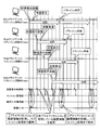
- FIG. 2 is a diagram showing a server device according to the second embodiment of the present case.
- the server device 200 is connected to four client devices (Web client A to Web client D) via a communication path such as a LAN.
- the server device 200 includes a Web server 210, a screen display control unit 220, a session management unit 230, a device H / W management unit 240, and a device H / W 250.
- the Web server 210 corresponds to the port 110
- the combination of the screen display control unit 220 and the session management unit 230 corresponds to the information transmission control unit 120.
- the Web server 210 is a service function realized by HTTP (Hyper Text Transfer Protocol).
- An information storage unit 221 in the screen display control unit 220 corresponds to the information storage unit 121.
- the device H / W 250 corresponds to the device H / W 140.
- the session management unit 230 specifies information for specifying the screen displayed on each of the Web clients A to D, and for the same screen, specifies the client device (referred to as “primary session”) that first displayed the screen. Information is stored. By referring to the session management unit 230, the screen information control unit 220 can know which Web client A to D is responsible for the screen currently displayed on each Web client A to D and the primary session.
- the differences between the server apparatus 200 shown in FIG. 2 and the server apparatus 100 shown in FIG. 1 are as described above.
- the operations of the Web server 210, the apparatus H / W management unit 240, and the apparatus H / W 250 are as follows. It is the same as the port 110, the device information acquisition unit 130, and the device H / W 140 of the server device 100 shown in FIG. That is, the Web server 210 is responsible for communication with the Web clients A to D.
- the device H / W management unit 240 accesses the device H / W 250 and acquires device information representing the state of the server device 200.
- the device H / W 250 includes various sensors, and receives the access from the device H / W management unit 240, and the measurement information collected by these sensors and the hardware constituting the server device 200
- the apparatus H / W management unit is made to acquire apparatus information including information regarding the apparatus.
- FIG. 3 is a flowchart showing the processing contents of the server device 200 shown in FIG.
- the Web server 210 transfers the status display request to the screen display control unit 220 ( S2).
- the “status display request” corresponds to the “information transmission request” in the server apparatus 100 of the first embodiment shown in FIG. 1, but here the status display screen on which the apparatus information is recorded in each Web client Is referred to as a “status display request”.
- the screen display control unit 220 makes an inquiry to the session management unit 230, and the Web client that transmitted the status display request received this time is the primary session that first displayed the status monitoring screen corresponding to the status display request. It is confirmed whether or not there is (S3).
- the device H / W management unit 240 is requested to acquire device information (S4).
- the device H / W management unit 240 accesses the device H / W 250, acquires device information representing the state of the server device, and passes the acquired device information to the screen display control unit 220 (S5).
- the screen display control unit 220 converts the acquired device information into screen information representing a screen on which the device information is displayed, and holds the device information converted into the screen information in the information storage unit 221 (S6).
- the device information is returned to the Web client responsible for the primary session that has transmitted the status display request this time (S8).
- step S3 When it is confirmed in step S3 that the session is a non-primary session, the device information held in the information storage unit 221 is acquired (S7), and the device information is the Web that has transmitted the screen display request for the non-primary session this time. Returned to the client (S8).
- the status monitoring screen when there is a status display request regarding another status monitoring screen from the Web client in charge of the primary session, the status monitoring screen so far recorded in the session management unit 230 shown in FIG.
- the primary session information is reset.
- the Web client that transmitted the status display request is recorded in the session management unit 230 as a new primary session.
- FIG. 4 is a timing chart showing the operation of the server apparatus shown in FIGS.
- three Web clients A to C send a new status display request every refresh interval 30 seconds, and the remaining one Web client D refreshes 60 seconds. Each time a new status display request is sent. Further, here, the same status display screen in which the device information of the entire server device 200 is recorded as the initial screen is displayed on the four Web clients A to D.
- the Web client A first transmits a status display request regarding the status display screen, and the status display request is received by the server device 200. That is, here, the Web client A is in charge of the primary session.
- the device H / W is accessed by the device H / W management unit, and new acquisition of device information is performed.
- device information held by the image display control unit is returned without newly acquiring device information by accessing the device H / W. .
- FIG. 5 is an operation timing chart of the server device as a comparative example.
- the operating conditions in the operation timing chart shown in FIG. 5 are the same as the operating conditions in the operation timing chart shown in FIG. 4 except that primary sessions and non-primary sessions are not distinguished.
- the device H / W is accessed for all status display requests transmitted from any of the Web clients A to D, and device information is newly acquired.
- the state monitoring screen that is initially displayed is often displayed for a long time, and the load on the server device is also affected when the above processing is performed only on the state monitoring screen that is displayed first. Is greatly reduced.
- the load on the server device is reduced, the processing capacity is increased, and for example, the number of Web clients that can be connected simultaneously can be increased. Further, the reduced load can be allocated to the original business of the server device.
- 10A, 10B Client device 100, 200 Server device 110 Port 120 Information transmission control unit 121, 221 Information storage unit 130 Device information acquisition unit 140, 250 Device H / W (hardware) 210 Web server 220 Screen display control unit 230 Session management unit 240 Device H / W management unit
Landscapes
- Engineering & Computer Science (AREA)
- Computer Networks & Wireless Communication (AREA)
- Signal Processing (AREA)
- Computer And Data Communications (AREA)
- Information Transfer Between Computers (AREA)
Abstract
本件は、通信路を介して複数の端末装置に接続された情報処理装置等に関し、装置情報収集の負荷の軽減を図るため、装置情報を記憶する情報記憶部を有し、情報送信要求を受信したことを受けて、同一種類の情報送信要求を最初に送信してきたプライマリセッションの端末装置については装置情報を新たに取得して送信するとともにその装置情報を記憶しておき、非プライマリセッションの端末装置についてはその記憶しておいた装置情報を送信する。
Description
本件は、情報処理装置及び制御方法に関する。
情報処理装置としてのサーバ装置には、そのサーバ装置に本来業務、例えば銀行における入出金処理業務等を行なわさせる端末装置としてのクライアント装置が接続され、サーバ装置はその本来業務を遂行する。このようなサーバ装置には、本来業務を遂行するクライアント装置だけでなく、さらにシステム制御用端末装置としてのシステム制御用のクライアント装置が接続される。そのサーバ装置では、システム制御用クライアントからの要求に応じて、そのサーバ装置内の各部のセンサの状態等からなる装置情報を取得しシステム制御用クライアント装置に送信する。システム制御用クライアントでは、その装置情報が表示され、オペレータによる、そのサーバ装置が正常に稼動しているか否かの監視に供される。サーバ装置の状態は刻々と変化するため、システム制御用クライアント装置はサーバ装置に向けて一定期間ごと(例えば30秒ごと)に新たな要求を行ない、サーバ装置から新たな装置情報を得て表示を更新する。
ここで、1台のサーバ装置にシステム制御用クライアント装置が複数台接続される場合がある。その場合、サーバ装置ではそれら複数台のクライアント装置それぞれからの要求に応じてサーバ装置内の各部のセンサの状態を取得したりなど、装置情報収集のための負荷が増加する。この負荷を抑えようとするとシステム制御用クライアント装置の同時接続数が制限されるなど、不都合を生じる。
ここで、サーバ装置との間が通信経路としてのネットワークで接続された複数のクライアント装置としての端末装置において、それら複数の端末装置のうちの1台でイベントを発生させるとそのイベントが複数の端末装置の全てに反映される技術が提案されている。この技術は複数の端末装置の表示形式を一致させようとするものである。また、複数の端末装置に同一の表示情報を表示形式を変えて同時に表示することが提案されている。
本件開示の情報処理装置及び制御方法の課題は、装置情報収集の負荷の軽減を図ることにある。
本件開示の情報処理装置は、通信路を介して複数の端末装置に接続された情報処理装置において、
複数の端末装置との間の通信を行う通信部と、
当該情報処理装置の状態を表わす装置情報を取得する装置情報取得部と、
装置情報取得部から受け取った装置情報を記憶する情報記憶部を有し、上記複数の端末装置のうちの、第1の状態監視画面に表示される装置情報の送信を要求する第1の情報送信要求を最初に送信してきた第1の端末装置から繰り返し送信される第1の情報送信要求を通信部が受信するたびに、装置情報取得部にその第1の情報送信要求に応じた装置情報の取得を要求し装置情報取得部から装置情報を受け取ってその装置情報を情報記憶部に記憶するとともにその装置情報を通信部に第1の端末装置に向けて送信させ、上記複数の端末装置のうちの、上記第1の端末装置を除く他の端末装置が送信した第1の情報送信要求を通信部が受信したことを受けて、情報記憶部に記憶された、その第1の情報送信要求に応じた装置情報を通信部にその第1の情報送信要求を送信した他の端末装置に向けて送信させる情報送信制御部と、
を有する情報処理装置である。
複数の端末装置との間の通信を行う通信部と、
当該情報処理装置の状態を表わす装置情報を取得する装置情報取得部と、
装置情報取得部から受け取った装置情報を記憶する情報記憶部を有し、上記複数の端末装置のうちの、第1の状態監視画面に表示される装置情報の送信を要求する第1の情報送信要求を最初に送信してきた第1の端末装置から繰り返し送信される第1の情報送信要求を通信部が受信するたびに、装置情報取得部にその第1の情報送信要求に応じた装置情報の取得を要求し装置情報取得部から装置情報を受け取ってその装置情報を情報記憶部に記憶するとともにその装置情報を通信部に第1の端末装置に向けて送信させ、上記複数の端末装置のうちの、上記第1の端末装置を除く他の端末装置が送信した第1の情報送信要求を通信部が受信したことを受けて、情報記憶部に記憶された、その第1の情報送信要求に応じた装置情報を通信部にその第1の情報送信要求を送信した他の端末装置に向けて送信させる情報送信制御部と、
を有する情報処理装置である。
本件開示の情報処理装置及び制御方法によれば、一旦取得した装置情報を記憶する情報記憶部を設け、第1の端末装置を除く他の端末装置には、記憶情報部に記憶された装置情報を送信することにより装置情報取得の負荷の軽減が図られる。
以下本件の実施形態を説明する。
図1は、本件の第1実施形態である情報処理装置としてのサーバ装置を示す図である。
このサーバ装置100は、通信路20を介して複数台(ここでは2台)のクライアント装置10A,10Bに接続されている。通信路20は、例えばLAN(Local Area Network)等のネットワークである。このサーバ装置100に接続されるクライアント装置は2台に限られるものではなく、3台以上であってもよい。このサーバ装置100は、通信部としてのポート110と、情報送信制御部120と、装置情報取得部130と、装置H/W(ハードウェア)140とを有する。装置H/W140は、ここでは1つのブロックで示しているが、このサーバ装置140の各部に広く分散配置され、例えば温度センサ、ファン回転速度センサ、電圧センサ、電流センサ、その他の様々のセンサを含むものである。また情報送信制御部120は、後述する装置情報を記憶する情報記憶部121を有する。
装置情報取得部130は、そのようにサーバ装置100内に広く分散配置された装置H/W140から、各センサが収集した計測情報や様々なハードウェア情報等からなる装置情報を収集、取得する。
ポート110は、クライアント装置10A,10Bとの間の通信を担うLANカード等の通信インタフェースである。
情報送信制御部120は、ポート110と装置情報取得部130との間に介在する。この情報送信制御部120は、装置情報取得部130から受け取った装置情報を記憶する情報記憶部121を有する。この情報送信制御部120は、クライアント装置10A,10Bのいずれかから送信されてきた情報送信要求をポート110が受信したことを受けて、その情報送信要求に応じた装置情報をポート110に送信させる。ポート110は、その情報送信要求に応じた装置情報を、その情報送信要求を送信してきたクライアント装置に向けて送信する。
ここでは各クライアント装置10A,10Bは、サーバ装置100に向けて一定周期で(例えば30秒周期で)、サーバ装置100のシステム監視用又は状態監視用として最初に状態監視画面上に表示される装置情報の送信の要求である情報送信要求を送信する。
ここでは、一方のクライアント装置10Aの方が初回の情報送信要求を行なうタイミングが他方のクライアント装置10Bよりも早かったものとする。ここでは、クライアント装置10Aから送信された情報送信要求のみを先に説明する。クライアント装置10Aから送信された情報送信要求がポート110で受信されると、情報送信制御部120は、装置情報取得部130に装置情報の取得を要求しその装置情報取得部130から装置情報を取得する。情報送信制御部120は、その取得した装置情報を情報記憶部121に記憶するとともに、その装置情報をポート110にクライアント装置10Aに向けて送信させる。情報記憶部121に装置情報を記憶するにあたっては、同一の状態監視画面上に表示される装置情報が情報記憶部121に存在するときは、上書き等によりその装置情報に代えて新たな装置情報を記憶する。クライアント装置10Aから次に情報送信要求が送信されてきた場合も同様にして、情報送信制御部120は、装置情報取得部130に装置情報の取得を再度要求し、その装置情報取得部130から装置情報を再度取得する。情報送信制御部120は、この再度取得した装置情報を情報記憶部121に記憶させるとともにポート110にクライアント装置10Aに向けて送信させる。これを繰り返すことにより、クライアント装置10Aには、装置情報が記録された状態表示画面が表示されて、その状態表示画面上の装置情報が一定周期(例えば30秒周期)で更新される。
ここで、クライアント装置10Bからも、クライアント装置10Aが要求した装置情報と同一の装置情報の送信を要求する装置情報送信要求がサーバ装置100に向けて同じ周期(例えば30秒周期)で繰り返し送信される。このクライアント装置10Bからの情報送信要求がポート110で受信されると、情報送信制御部120は、情報記憶部121を参照する。その情報記憶部121にはクライアント装置10Aからの直前の情報取得要求を受信した際に取得した装置情報が記憶されている。そこで、情報送信制御部120は、サーバ装置内の各部のセンサの状態等からなる装置情報を新たに取得することなく、その情報記憶部121に記憶されている装置情報を読み出して、ポート110にクライアント装置10Bに向けて送信させる。このように、クライアント装置10Bについては、情報送信要求を受信するたびに、サーバ装置内の各部のセンサの状態等からなる装置情報を新たに取得することなく、情報記憶部121に記憶されている装置情報がポート110から送信される。クライアント装置10Bには、これにより、クライアント装置10Aと同様に、状態監視画面上に一定周期(例えば30秒周期)で更新された装置情報が表示される。
このように、図1のサーバ装置100によれば、クライアント装置10Aからの要求に応じて装置情報の新たな取得が行なわれ、クライアント装置10Bからの要求については装置情報の新たな取得がされることなく記憶された装置情報が送信される。この場合、双方のクライアント装置10A,10Bそれぞれからの情報送信要求の全てについて装置情報の新たな取得を行なう場合と比べ装置情報の取得処理は半減する。したがって装置情報取得の負荷が軽減される。
図2は、本件の第2実施形態のサーバ装置を示す図である。
このサーバ装置200は、LAN等の通信路を介して4台のクライアント装置(WebクライアントA~WebクライアントD)が接続されている。このサーバ装置200は、Webサーバ210、画面表示制御部220、セッション管理部230、装置H/W管理部240、および装置H/W250を有する。ここで、図1に示す第1実施形態との対比では、Webサーバ210がポート110に対応し、画面表示制御部220とセッション管理部230とを合わせたものが情報送信制御部120に対応する。Webサーバ210とは、具体的にHTTP(Hyper Text Transfer Protocol)により実現されるサービス機能である。また、画面表示制御部220内の情報記憶部221が情報記憶部121に相当する。さらに、装置H/W250は装置H/W140に相当する。
セッション管理部230には、各WebクライアントA~Dに表示されている画面を特定する情報や、同一の画面についてはその画面を最初に表示したクライアント装置(「プライマリセッション」と称する)を特定する情報が格納されている。画面情報制御部220は、セッション管理部230を参照することにより、各WebクライアントA~Dで現在表示されている画面やプライマリセッションをどのWebクライアントA~Dが担っているかを知ることができる。
この図2に示すサーバ装置200における図1に示すサーバ装置100との相違点は、以上の点であり、Webサーバ210、装置H/W管理部240、および装置H/W250の各動作は、図1に示すサーバ装置100の、ポート110、装置情報取得部130、および装置H/W140と同じである。すなわち、Webサーバ210は、WebクライアントA~Dとの間の通信を担っている。また、装置H/W管理部240は、装置H/W250をアクセスしてこのサーバ装置200の状態を表わす装置情報を取得する。また、装置H/W250には、各種のセンサが含まれており、装置H/W管理部240からのアクセスを受けて、それらのセンサが収集した計測情報やこのサーバ装置200を構成するハードウェアに関する情報等からなる装置情報を装置H/W管理部に取得させる。
図3は、図2に示すサーバ装置200の処理内容を示したフローチャートである。
WebクライアントA~Dのいずれかから状態表示依頼が発行されWebサーバ210によりその状態表示依頼が受信されると(S1)、Webサーバ210はその状態表示依頼を画面表示制御部220に転送する(S2)。
ここで、「状態表示依頼」は図1に示す第1実施形態のサーバ装置100における「情報送信要求」に相当するものであるが、ここでは各Webクライアントにおいて装置情報が記録された状態表示画面が表示されることを考慮して「状態表示依頼」と称している。
次に、画面表示制御部220は、セッション管理部230に問い合わせて、今回受け取った状態表示依頼を送信してきたWebクライアントが、その状態表示依頼に対応する状態監視画面を最初に表示したプライマリセッションであるか否かを確認する(S3)。プライマリセッションのときは、装置H/W管理部240に装置情報の取得を依頼する(S4)。装置H/W管理部240は、装置H/W250をアクセスし、このサーバ装置の状態を表わす装置情報を取得して、その取得した装置情報を画面表示制御部220に渡す(S5)。画面表示制御部220は、その取得した装置情報を、その装置情報を表示する画面を表わす画面情報に変換して、その画面情報に変換した装置情報を情報記憶部221に保持する(S6)。
次いで、その装置情報が、状態表示依頼を今回送信してきた、プライマリセッションを担っているWebクライアントに返却される(S8)。
ステップS3で非プライマリセッションであると確認されたときは、情報記憶部221に保持した装置情報が取得され(S7)、その装置情報が、非プライマリセッションの、画面表示依頼を今回送信してきたWebクライアントに返却される(S8)。
ここで、プライマリセッションを担っているWebクライアントから別の状態監視画面に関する状態表示依頼があったときは、図2に示すセッション管理部230にそれまで記録されていた、それまでの状態監視画面についてのプライマリセッションの情報がリセットされる。そして、次にその状態表示画面に関する状態表示依頼があったときに、その状態表示依頼を送信したWebクライアントが新たなプライマリセッションとしてセッション管理部230に記録される。
図4は、図2,図3に示すサーバ装置の動作を示すタイミングチャートである。
ここでは4台のWebクライアントA~Dのうちの3台のWebクライアントA~Cはリフレッシュ間隔30秒ごとに新たな状態表示依頼を送信し、残りの1台のWebクライアントDはリフレッシュ間隔60秒ごとに新たな状態表示依頼を送信する。また、ここでは、4台のWebクライアントA~Dに、初期画面としての、サーバ装置200の全体の装置情報を記録した同一の状態表示画面が表示される。ここでは、WebクライアントAがその状態表示画面に関する状態表示依頼を最初に送信してその状態表示依頼がサーバ装置200に受信されたものとする。すなわち、ここではWebクライアントAがプライマリセッションを担っている。
この場合、WebクライアントAから送信された状態表示依頼については、装置H/W管理部により装置H/Wがアクセスされて装置情報の新たな取得が行なわれる。他のWebクライアントB~Dから送信された状態表示依頼については、装置H/Wのアクセスによる装置情報の新たな取得は行なわれずに、画像表示制御部が保持している装置情報が返却される。
図5は、比較例としてのサーバ装置の動作タイミングチャートである。
この図5に示す動作タイミングチャートにおける動作条件は、プライマリセッションと非プライマリセッションとを区別していないこと以外は、図4に示す動作タイミングチャートにおける動作条件と同一である。
この図5に示す比較例としてのサーバ装置の場合、どのWebクライアントA~Dから送信されてきた状態表示依頼についても、全て装置H/Wがアクセスされて装置情報が新たに取得される。
図4と図5とを比較すると分かるように、図4の場合、非プライマリセッションでは新たな装置H/Wのアクセスは行なわれず、これらの装置情報取得の負荷が大きく軽減される。
尚、ここでは、複数種類の状態監視画面が存在するときにそれら複数種類の状態監視画面それぞれについてプライマリセッションを設定することを念頭に置いた説明を行ったが、プライマリセッションを設定するのは、それら複数種類のうちの一部のみでもよい。例えば、サーバ装置の状態監視用として最初に表示される状態監視画面のみ、図3,図4に示すようなプライマリセッションと非プライマリセッションとに分けた処理を行ってもよい。各WebクライアントA~Dでは、最初に表示される状態監視画面が長時間表示されることが多く、この最初に表示される状態監視画面のみについて上記の処理を行なった場合にもサーバ装置の負荷の大幅な軽減が図られる。このサーバ装置の負荷が軽減されると処理能力に余裕が出るため、例えば同時接続可能なWebクライアントの数を増加させることができる。また、その負荷の軽減分をそのサーバ装置の本来業務に振り分けることができる。
10A,10B クライアント装置
100,200 サーバ装置
110 ポート
120 情報送信制御部
121,221 情報記憶部
130 装置情報取得部
140,250 装置H/W(ハードウェア)
210 Webサーバ
220 画面表示制御部
230 セッション管理部
240 装置H/W管理部
100,200 サーバ装置
110 ポート
120 情報送信制御部
121,221 情報記憶部
130 装置情報取得部
140,250 装置H/W(ハードウェア)
210 Webサーバ
220 画面表示制御部
230 セッション管理部
240 装置H/W管理部
Claims (8)
- 通信路を介して複数の端末装置に接続された情報処理装置において、
前記複数の端末装置との間の通信を行う通信部と、
当該情報処理装置の状態を表わす装置情報を取得する装置情報取得部と、
前記装置情報取得部から受け取った装置情報を記憶する情報記憶部を有し、前記複数の端末装置のうちの、第1の状態監視画面に表示される装置情報の送信を要求する第1の情報送信要求を最初に送信してきた第1の端末装置から繰り返し送信される該第1の情報送信要求を前記通信部が受信するたびに、前記装置情報取得部に該第1の情報送信要求に応じた装置情報の取得を要求し該装置情報取得部から該装置情報を受け取って該装置情報を前記情報記憶部に記憶するとともに該装置情報を前記通信部に前記第1の端末装置に向けて送信させ、前記複数の端末装置のうちの、前記第1の端末装置を除く他の端末装置が送信した前記第1の情報送信要求を前記通信部が受信したことを受けて、前記情報記憶部に記憶された、該第1の情報送信要求に応じた装置情報を前記通信部に該他の端末装置に向けて送信させる情報送信制御部と、
を有することを特徴とする情報処理装置。 - 前記情報処理装置において、
前記情報送信制御部は、
前記第1の端末装置から前記第1の情報送信要求を除く他の情報送信要求が送信されてきた後は、前記第1の情報送信要求を次に送信してきた端末装置を新たな第1の端末装置としたときの該新たな第1の端末装置からの該第1の情報送信要求を前記通信部が受信したことを受けて、前記装置情報取得部に該第1の情報送信要求に応じた装置情報の取得を要求し該装置情報取得部から該装置情報を受け取って該装置情報を前記情報記憶部に記憶するとともに該装置情報を前記通信部に前記新たな第1の端末装置に向けて送信させ、前記複数の端末装置のうちの前記新たな第1の端末装置を除く他の端末装置が送信した前記第1の情報送信要求を前記通信部が受信したことを受けて、前記情報記憶部に記憶された、該第1の情報送信要求に応じた装置情報を前記通信部に該他の端末装置に向けて送信させることを特徴とする請求項1記載の情報処理装置。 - 前記情報処理装置において、
前記第1の状態監視画面には、少なくとも、前記複数の端末装置それぞれにおいて当該情報処理装置の状態監視用として最初に表示される状態監視画面が含まれることを特徴とする請求項1記載の情報処理装置。 - 前記情報処理装置において、
前記情報送信制御部は、
前記装置情報取得部から受け取った装置情報を、該装置情報を表示する画面を表わす画面情報に変換して前記情報記憶部に記憶し、および、前記通信部が前記端末装置から情報送信要求を受信したことを受けて前記画面情報を前記通信部に送信させることを特徴とする請求項1から3のうちいずれか1項記載の情報処理装置。 - 通信路を介して複数の端末装置に接続された、該複数の端末装置との間の通信を行う通信部と、当該情報処理装置の状態を表わす装置情報を取得する装置情報取得部と、該装置情報取得部から受け取った装置情報を記憶する情報記憶部とを有する情報処理装置で実行される、当該情報処理装置から前記端末装置に向けた送信を制御する制御方法において、
前記複数の端末装置のうちの、第1の状態監視画面に表示される装置情報の送信を要求する第1の情報送信要求を最初に送信してきた第1の端末装置から繰り返し送信される該第1の情報送信要求を前記通信部が受信するたびに、前記装置情報取得部に該第1の情報送信要求に応じた装置情報の取得を要求させ該装置情報取得部から該装置情報を受け取らせて該装置情報を前記情報記憶部に記憶させるとともに該装置情報を前記通信部に前記第1の端末装置に向けて送信させ、
前記複数の端末装置のうちの、前記第1の端末装置を除く他の端末装置が送信した前記第1の情報送信要求を前記通信部が受信したことを受けて、前記情報記憶部に記憶された、該第1の情報送信要求に応じた装置情報を前記通信部に該他の端末装置に向けて送信させることを特徴とする制御方法。 - 前記第1の端末装置から前記第1の情報送信要求を除く他の情報送信要求が送信されてきた後は、前記第1の情報送信要求を次に送信してきた端末装置を新たな第1の端末装置としたときの該新たな第1の端末装置からの該第1の情報送信要求を前記通信部が受信したことを受けて、前記装置情報取得部に該第1の情報送信要求に応じた装置情報の取得を要求させ該装置情報取得部から該装置情報を受け取らせて該装置情報を前記情報記憶部に記憶させるとともに該装置情報を前記通信部に前記新たな第1の端末装置に向けて送信させ、
前記複数の端末装置のうちの前記新たな第1の端末装置を除く他の端末装置が送信した前記第1の情報送信要求を前記通信部が受信したことを受けて、前記情報記憶部に記憶された、該第1の情報送信要求に応じた装置情報を前記通信部に該他の端末装置に向けて送信させることを特徴とする請求項5記載の制御方法。 - 前記第1の状態監視画面には、少なくとも、前記複数の端末装置それぞれにおいて当該情報処理装置の状態監視用として最初に表示される状態監視画面が含まれることを特徴とする請求項5記載の制御方法。
- 前記装置情報取得部から受け取った装置情報を前記情報記憶部に記憶させるにあたり、該装置情報を表示する画面を表わす画面情報に変換させてから前記情報記憶部に記憶させ、前記通信部が前記端末装置から情報送信要求を受信したことを受けて前記画面情報を前記通信部に送信させることを特徴とする請求項5から7のうちいずれか1項記載の制御方法。
Priority Applications (3)
| Application Number | Priority Date | Filing Date | Title |
|---|---|---|---|
| PCT/JP2009/070765 WO2011070677A1 (ja) | 2009-12-11 | 2009-12-11 | 情報処理装置及び制御方法 |
| JP2011545035A JP5370495B2 (ja) | 2009-12-11 | 2009-12-11 | 情報処理装置及び制御方法 |
| US13/485,200 US8825850B2 (en) | 2009-12-11 | 2012-05-31 | Information processing apparatus and control method |
Applications Claiming Priority (1)
| Application Number | Priority Date | Filing Date | Title |
|---|---|---|---|
| PCT/JP2009/070765 WO2011070677A1 (ja) | 2009-12-11 | 2009-12-11 | 情報処理装置及び制御方法 |
Related Child Applications (1)
| Application Number | Title | Priority Date | Filing Date |
|---|---|---|---|
| US13/485,200 Continuation US8825850B2 (en) | 2009-12-11 | 2012-05-31 | Information processing apparatus and control method |
Publications (1)
| Publication Number | Publication Date |
|---|---|
| WO2011070677A1 true WO2011070677A1 (ja) | 2011-06-16 |
Family
ID=44145246
Family Applications (1)
| Application Number | Title | Priority Date | Filing Date |
|---|---|---|---|
| PCT/JP2009/070765 Ceased WO2011070677A1 (ja) | 2009-12-11 | 2009-12-11 | 情報処理装置及び制御方法 |
Country Status (3)
| Country | Link |
|---|---|
| US (1) | US8825850B2 (ja) |
| JP (1) | JP5370495B2 (ja) |
| WO (1) | WO2011070677A1 (ja) |
Families Citing this family (1)
| Publication number | Priority date | Publication date | Assignee | Title |
|---|---|---|---|---|
| CN104539674A (zh) * | 2014-12-18 | 2015-04-22 | 百度在线网络技术(北京)有限公司 | 通讯方法及装置 |
Citations (2)
| Publication number | Priority date | Publication date | Assignee | Title |
|---|---|---|---|---|
| JP2004178371A (ja) * | 2002-11-28 | 2004-06-24 | Yamatake Corp | 表示データ配信方法および表示データ配信プログラム |
| JP2004318572A (ja) * | 2003-04-17 | 2004-11-11 | Yaskawa Electric Corp | リモートメンテナンス用クライアント・サーバシステムにおける複数クライアント間の画面情報共有方法 |
Family Cites Families (15)
| Publication number | Priority date | Publication date | Assignee | Title |
|---|---|---|---|---|
| JPH03268048A (ja) | 1990-03-19 | 1991-11-28 | Toshiba Corp | 窓口端末装置の情報表示方式 |
| US20030158932A1 (en) * | 1998-10-02 | 2003-08-21 | Haruo Machida | System for displaying connection condition of device provided on network |
| JP2000194583A (ja) * | 1998-12-25 | 2000-07-14 | Nissin Electric Co Ltd | 監視制御システム、および、そのプログラムが記録された記録媒体 |
| US6742059B1 (en) * | 2000-02-04 | 2004-05-25 | Emc Corporation | Primary and secondary management commands for a peripheral connected to multiple agents |
| JP2001243165A (ja) | 2000-03-02 | 2001-09-07 | Fujitsu Ltd | 共有情報利用システム、方法及び記憶媒体 |
| JP2002189641A (ja) * | 2000-12-21 | 2002-07-05 | Nec Eng Ltd | 監視システム |
| JP2002194583A (ja) | 2000-12-28 | 2002-07-10 | Nikon Corp | 精密電鋳品の製造方法及び電鋳装置 |
| US7899900B1 (en) * | 2002-08-22 | 2011-03-01 | Ricoh Company, Ltd. | Method and system for monitoring network connected devices with multiple protocols |
| US20060168195A1 (en) * | 2004-12-15 | 2006-07-27 | Rockwell Automation Technologies, Inc. | Distributed intelligent diagnostic scheme |
| US9401822B2 (en) * | 2005-06-09 | 2016-07-26 | Whirlpool Corporation | Software architecture system and method for operating an appliance exposing key press functionality to a network |
| WO2008008899A2 (en) * | 2006-07-12 | 2008-01-17 | Arbitron Inc. | Methods and systems for compliance confirmation and incentives |
| KR101394155B1 (ko) * | 2007-07-24 | 2014-05-14 | 삼성전자주식회사 | 기기에서 수행하는 상태 표시 방법 및 그 기기 |
| JP5245612B2 (ja) * | 2007-07-31 | 2013-07-24 | セイコーエプソン株式会社 | ポスティングサーバ、および、ポスティングサーバ制御方法 |
| JP5142745B2 (ja) * | 2008-02-12 | 2013-02-13 | キヤノン株式会社 | デバイス管理システム、デバイス管理方法、情報処理装置、情報処理方法、プログラムおよび記憶媒体 |
| WO2011055406A1 (en) * | 2009-11-04 | 2011-05-12 | Hitachi, Ltd. | Data storage system and method therefor |
-
2009
- 2009-12-11 WO PCT/JP2009/070765 patent/WO2011070677A1/ja not_active Ceased
- 2009-12-11 JP JP2011545035A patent/JP5370495B2/ja not_active Expired - Fee Related
-
2012
- 2012-05-31 US US13/485,200 patent/US8825850B2/en not_active Expired - Fee Related
Patent Citations (2)
| Publication number | Priority date | Publication date | Assignee | Title |
|---|---|---|---|---|
| JP2004178371A (ja) * | 2002-11-28 | 2004-06-24 | Yamatake Corp | 表示データ配信方法および表示データ配信プログラム |
| JP2004318572A (ja) * | 2003-04-17 | 2004-11-11 | Yaskawa Electric Corp | リモートメンテナンス用クライアント・サーバシステムにおける複数クライアント間の画面情報共有方法 |
Also Published As
| Publication number | Publication date |
|---|---|
| JPWO2011070677A1 (ja) | 2013-04-22 |
| US20120239806A1 (en) | 2012-09-20 |
| US8825850B2 (en) | 2014-09-02 |
| JP5370495B2 (ja) | 2013-12-18 |
Similar Documents
| Publication | Publication Date | Title |
|---|---|---|
| US8122124B1 (en) | Monitoring performance and operation of data exchanges | |
| JP4531794B2 (ja) | インターネットを通じてUPnPホームネットワークに接続されたデバイスを制御する方法及びそのためのシステム及び装置 | |
| US7917615B2 (en) | Apparatus and method for real-time monitoring and controlling of networked appliances using an intermediate server | |
| JP4337591B2 (ja) | 情報処理装置、ネットワークシステムおよびネットワークシステムの制御方法 | |
| US9002987B2 (en) | Method and apparatus for reproducing content in multimedia data providing system | |
| JP2011128957A (ja) | メディア情報共有システムおよびメディア情報共有方法 | |
| CN101325553B (zh) | Iscsi数据穿越nat的方法和内网存储系统 | |
| CN111600883A (zh) | 一种车辆诊断方法、系统及电子设备和存储介质 | |
| KR101353933B1 (ko) | 멀티 포트를 구비하는 화상형성장치, 및 통신 포트를제공하는 호스트 그리고, 그들의 통신포트 제공방법 | |
| JP5370495B2 (ja) | 情報処理装置及び制御方法 | |
| KR102151867B1 (ko) | 통신 시스템 | |
| JP6385254B2 (ja) | 監視システム、監視サーバ及び監視システムの制御方法 | |
| US9380115B2 (en) | Event processing system and event processing method | |
| WO2012081662A1 (ja) | 管理装置、および、コンテンツ提供システム | |
| JP3933655B2 (ja) | ネットワークアプリケーション障害原因切り分け装置及び該障害原因切り分けプログラム | |
| KR101104727B1 (ko) | 캐시서버 및 브라우저캐시를 이용한 컨텐츠 전송시스템 및 방법 | |
| JP5441167B2 (ja) | ルータ装置、転送制御方法および転送制御プログラム | |
| CN112291209B (zh) | 一种前端设备目录获取方法及装置 | |
| KR101241736B1 (ko) | 포트 포워딩 설정 방법, 이를 이용한 네트워크 단말장치 및 네트워크 시스템 | |
| KR101066871B1 (ko) | 캐시서버 및 브라우저캐시를 이용한 컨텐츠 전송시스템 및 방법 | |
| CN112291210B (zh) | 一种前端设备目录获取方法及装置 | |
| CN105704194B (zh) | 远程控制方法、客服端、用户端以及系统 | |
| JP5732949B2 (ja) | 情報収集装置、情報収集プログラム及び監視システム | |
| EP4664856A1 (en) | A data exchange system including a microservice client aggregator | |
| CN104380789A (zh) | 用于根据通信网络的类型提供内容的方法和装置 |
Legal Events
| Date | Code | Title | Description |
|---|---|---|---|
| 121 | Ep: the epo has been informed by wipo that ep was designated in this application |
Ref document number: 09852073 Country of ref document: EP Kind code of ref document: A1 |
|
| WWE | Wipo information: entry into national phase |
Ref document number: 2011545035 Country of ref document: JP |
|
| NENP | Non-entry into the national phase |
Ref country code: DE |
|
| 122 | Ep: pct application non-entry in european phase |
Ref document number: 09852073 Country of ref document: EP Kind code of ref document: A1 |