WO2011058656A1 - ハンドヘルド点字変換装置、点字変換方法、点字変換プログラム及び記憶媒体 - Google Patents
ハンドヘルド点字変換装置、点字変換方法、点字変換プログラム及び記憶媒体 Download PDFInfo
- Publication number
- WO2011058656A1 WO2011058656A1 PCT/JP2009/069439 JP2009069439W WO2011058656A1 WO 2011058656 A1 WO2011058656 A1 WO 2011058656A1 JP 2009069439 W JP2009069439 W JP 2009069439W WO 2011058656 A1 WO2011058656 A1 WO 2011058656A1
- Authority
- WO
- WIPO (PCT)
- Prior art keywords
- braille
- unit
- display
- character
- handheld
- Prior art date
- Legal status (The legal status is an assumption and is not a legal conclusion. Google has not performed a legal analysis and makes no representation as to the accuracy of the status listed.)
- Ceased
Links
Images








Classifications
-
- G—PHYSICS
- G09—EDUCATION; CRYPTOGRAPHY; DISPLAY; ADVERTISING; SEALS
- G09B—EDUCATIONAL OR DEMONSTRATION APPLIANCES; APPLIANCES FOR TEACHING, OR COMMUNICATING WITH, THE BLIND, DEAF OR MUTE; MODELS; PLANETARIA; GLOBES; MAPS; DIAGRAMS
- G09B21/00—Teaching, or communicating with, the blind, deaf or mute
- G09B21/001—Teaching or communicating with blind persons
- G09B21/003—Teaching or communicating with blind persons using tactile presentation of the information, e.g. Braille displays
- G09B21/004—Details of particular tactile cells, e.g. electro-mechanical or mechanical layout
-
- G—PHYSICS
- G06—COMPUTING OR CALCULATING; COUNTING
- G06V—IMAGE OR VIDEO RECOGNITION OR UNDERSTANDING
- G06V30/00—Character recognition; Recognising digital ink; Document-oriented image-based pattern recognition
- G06V30/10—Character recognition
- G06V30/14—Image acquisition
- G06V30/142—Image acquisition using hand-held instruments; Constructional details of the instruments
Definitions
- the present invention relates to a technique for converting characters into Braille.
- braille display device that converts the electronic data of one column of characters into braille and displays it.
- Patent Document 1 describes an electronic data display system that displays text data in a computer after converting it into Braille.
- the braille display device described above has a problem that characters on printed matter cannot be easily converted into braille on the spot.
- the invention according to claim 1 is a handheld Braille conversion device that can be moved while being held by one hand of a user, and at least one finger of the hand holding the handheld Braille conversion device is in contact
- a braille display unit that is arranged at a possible position and displays braille, an imaging unit that captures a predetermined range around the handheld Braille conversion device, and detects the presence or absence of characters present in the captured image of the imaging unit
- Character recognition means for recognizing characters
- Braille conversion means for converting part or all of the characters recognized by the character recognition means into Braille
- display control for displaying the Braille converted by the Braille conversion means on the Braille display unit
- the Braille display unit has a plurality of unit Braille display units each corresponding to one Braille, and the unit Braille display unit has a plurality of movable members
- the display control means displays the suitability of the positional relationship of the handheld Braille conversion device with respect to characters or character strings existing in the captured image by operating members of some of the unit Braille display units.
- the invention according to claim 9 is a braille that can be moved in a state where the user holds it with one hand, and is arranged at a position where at least one finger of the holding hand can touch and displays braille.
- a display control step wherein the braille display unit includes a plurality of unit braille display units each corresponding to one braille, the unit braille display unit includes a plurality of movable members,
- the display control step displays whether or not the handheld Braille converting device is appropriate for the character or the character string existing in the photographed image by operating members of some of the
- the invention according to claim 10 can be moved while the user is holding it with one hand, and is arranged in a position where at least one finger of the holding hand can be contacted to display braille.
- a Braille conversion program executed by a handheld Braille conversion device including a display unit, which detects a presence of characters present in a captured image of the imaging unit and an imaging unit that captures a predetermined range around the handheld Braille conversion device
- a character recognition means for recognizing existing characters, a Braille conversion means for converting part or all of the characters recognized by the character recognition means into Braille, and a Braille character converted by the Braille conversion means is displayed on the Braille display section.
- the handheld braille conversion device is made to function as a display control means, and the braille display section has a plurality of unit braille display sections each corresponding to one braille,
- the unit braille display unit has a plurality of movable members, and the display control means is present in the photographed image by operating members of some unit braille display units of the unit braille display units. Displaying the suitability of the positional relationship of the handheld braille conversion device with respect to the character or character string to be displayed, and displaying braille by operating members of the unit braille display unit other than the part unit braille display unit And
- a handheld Braille conversion device that can be moved while being held by a user with one hand, and at least one finger of a hand holding the handheld Braille conversion device can be contacted
- Character recognition means for recognizing the character
- Braille conversion means for converting part or all of the characters recognized by the character recognition means into Braille
- display control means for displaying the Braille converted by the Braille conversion means on the Braille display unit
- the Braille display unit has a plurality of unit Braille display units each corresponding to one Braille
- the unit Braille display unit has a plurality of movable members
- the display control means displays the suitability of the positional relationship of the handheld Braille conversion device with respect to characters or character strings existing in the captured image by operating members of some of the unit Braille display units.
- braille is displayed by operating members of the unit braille display units other than the part of unit braille display units.
- the handheld Braille conversion device includes a Braille display unit, an imaging unit, a character recognition unit, a Braille conversion unit, and a display control unit, and completes the process from reading characters to outputting Braille.
- the handheld Braille converting device is of a size that can be held with one hand. Accordingly, it is possible to provide a Braille conversion device that is easy for the user to carry and can easily convert a nearby character into Braille on the spot.
- the Braille display unit has a plurality of unit Braille display units each corresponding to one Braille, and the unit Braille display unit has a plurality of movable members.
- the member is a member such as a pin or a sphere.
- a display control means displays the propriety of the positional relationship of the handheld braille converting apparatus with respect to the character or character string which exists in a picked-up image by operating the member which some unit braille display parts among unit braille display parts operate. . Further, the display control means displays braille by operating members of other unit braille display units.
- the handheld Braille converting device can display Braille and guide the user's operation by combining a plurality of unit Braille display units. Therefore, it is possible to reduce the manufacturing cost, reduce the weight, reduce the size, etc. of the handheld Braille conversion device.
- the unit braille display units are installed side by side, and the display control unit operates the members of the unit braille display units located at both ends of the unit braille display unit, Appropriateness of the positional relationship of the handheld Braille converting device with respect to characters or character strings present in the photographed image is displayed.
- the handheld Braille converting device can clearly transmit the direction to be guided to the user by displaying the appropriateness of the positional relationship by the unit Braille display units at both ends.
- the display control unit operates a member included in the unit Braille display unit so that the position of the handheld Braille conversion device exists in the captured image. Indicates in which direction the character or character string is displaced.
- the user confirms the operation of the predetermined member with a finger, so that the position of the handheld Braille conversion device is shifted with respect to the character or the character string. You can know the direction.
- the display control means indicates the presence / absence of characters present in the captured image by operating a member of the unit Braille display unit.
- the user can know whether or not a character exists in the captured image by confirming the operation of the predetermined member with a finger. Further, the user can know that character recognition could not be performed or braille conversion could not be performed if braille characters were not displayed despite the presence of characters in the captured image.
- the display control unit operates a member included in the unit Braille display unit so that a character string existing in the captured image is written horizontally or vertically. Indicates whether it is a writing.
- the user confirms the operation of the predetermined member with his / her finger to determine whether the character string existing in the captured image is horizontal writing or vertical writing, and sets the handheld Braille conversion device in an appropriate direction. Can be moved.
- the display control unit operates a member included in the unit Braille display unit to change a direction of an initial of a character string existing in the captured image.
- the “initial character” refers to a character that the user should read first among one or more character strings displayed in the captured image.
- the user can move the handheld Braille conversion device in the direction of the initial letter of the character string existing in the captured image by confirming the operation of the predetermined member with the finger.
- the display control means vibrates the operation of raising or lowering the members of the some unit Braille display units to form or not form a convex shape.
- the suitability of the positional relationship is displayed, and Braille is displayed by raising or lowering the members of the unit braille display units other than the part of unit braille display units so as not to form a convex shape.
- the user can clearly distinguish and recognize the part displaying the propriety of the positional relationship and the part displaying the Braille in the Braille display unit.
- the Braille conversion unit calculates an average character width of each character constituting a character string to be displayed in Braille, and the number of Braille corresponding to the character string.
- the display control means changes the display of Braille based on the average character width and the number of Braille.
- the display control means redisplays the braille considering the average character width of the characters and the number of brailles corresponding to the entire character string.
- the “number of braille characters” refers to the number of times braille is displayed when displaying the braille of the entire character string by one unit braille display unit.
- a braille display that can be moved while being held with one hand by a user and displays braille arranged at a position where at least one finger of the holding hand can touch.
- a braille conversion method executed by a handheld Braille conversion device including a unit, which detects a presence of characters present in a captured image of a predetermined range around the handheld Braille conversion device and a captured image of the imaging step
- the Braille display unit has a plurality of unit Braille display units each corresponding to one Braille
- the unit Braille display unit has a plurality of movable members
- the display control step displays whether or not the handheld Braille converting device is appropriate for the character or the character string existing in the photographed image by operating members included in some of the unit Braille display units.
- braille that can be moved while being held by one hand of a user and displays braille arranged at a position where at least one finger of the held hand can be contacted.
- a Braille conversion program executed by a handheld Braille conversion device including a display unit, which detects a presence of characters present in a captured image of the imaging unit and an imaging unit that captures a predetermined range around the handheld Braille conversion device
- a character recognition means for recognizing existing characters, a Braille conversion means for converting part or all of the characters recognized by the character recognition means into Braille, and a Braille character converted by the Braille conversion means is displayed on the Braille display section.
- the handheld braille conversion device is made to function as a display control means for causing the braille display section to have a plurality of unit braille display sections each corresponding to one braille.
- the unit braille display unit has a plurality of movable members, and the display control means is present in the captured image by operating members of some unit braille display units of the unit braille display units. Whether the handheld braille conversion device is properly positioned with respect to the character or character string to be displayed is displayed, and braille is displayed by operating members of the unit braille display unit other than the part unit braille display unit.
- the handheld Braille conversion device can perform Braille conversion on characters on the spot by executing this Braille conversion program.
- the braille conversion program is stored in a storage medium.
- FIG. 1 is a diagram schematically showing a handheld Braille converting device 1 according to the present embodiment of the present invention.
- the handheld Braille converting device 1 includes a Braille display unit 10, a CPU 11, a RAM 12, a ROM 13, a power supply 14, a camera 15, a lens 16, and an illumination LED 17.
- the Braille display unit 10 includes a plurality of movable pins 21 as shown, and displays the Braille by raising and lowering the pins to form a convex shape. Details of the arrangement of the movable pins 21 will be described later.
- the camera 15 shoots a predetermined range around the handheld Braille conversion device 1 when the user places the handheld Braille conversion device 1 on the printed material, and transmits the captured image to the CPU 11.
- the camera 15 can be a CCD camera, for example.
- the CPU 11 executes the program stored in the RAM 12 or the ROM 13 in advance to detect the presence or absence of characters in the captured image acquired from the camera 15, and if there are characters, OCR (Optical Character Recognition; optical character recognition). Characters are recognized by executing processing.
- the CPU 11 refers to the dictionary information that associates kanji and reading stored in the memory such as the RAM 12 and the ROM 13 and the braille definition information that associates reading and braille, or character and braille, and recognizes the recognized character. Convert to braille. Then, the CPU 11 displays the converted braille on the braille display unit 10.
- the power supply 14 supplies power to the handheld Braille conversion device 1.
- the lens 16 is a lens of the camera, and the illumination LED 17 is a light source required when the camera 15 captures characters.
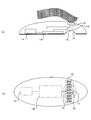
- FIG. 2 shows the structure of the handheld Braille converting device 1 according to this embodiment of the present invention.
- FIG. 2A is a side perspective view showing the internal structure of the handheld Braille converting device 1
- FIG. 2B is an overhead view showing the internal structure of the handheld Braille converting device 1 with a broken line.
- the handheld Braille conversion device 1 is a handheld device that can be moved while being held with one hand by a user, and includes a Braille display unit 10, a power supply 14, a camera 15, a lens 16, an illumination LED 17, and a system controller 19. .
- the camera 15 and the system controller 19, the system controller 19 and the braille display unit 10, and the system controller 19 and the power source 14 are electrically connected by wiring.
- the Braille display unit 10 is disposed at a position where the user can contact the Braille display unit 10 with at least one of the index finger, the middle finger, and the ring finger while holding the handheld Braille conversion device 1 with the thumb and little finger of one hand. Yes.
- the camera 15, the lens 16, and the illumination LED 17 are disposed in the immediate vicinity of the braille display unit 10.
- a portion immediately below the braille display portion 10 and a portion within a predetermined distance from this portion are defined as a directly lower periphery.
- the predetermined distance is 3 cm, for example.
- the system controller 19 includes a CPU 11, a RAM 12, and a ROM 13, and controls the entire handheld Braille conversion device 1.
- the power source 14 is configured by a battery, for example, and supplies power to the system controller 19 and supplies power to each component via the system controller 19.
- the power supply 14 may supply power directly to each component without using the system controller 19.
- FIG. 3 is an example of a block diagram illustrating a functional configuration of the handheld Braille conversion device 1 of the present embodiment. These functions are realized by the components shown in FIG.
- the handheld Braille conversion device 1 includes the camera 15, the CPU 11, the ROM 13, and the Braille display unit 10 as described above.
- the CPU 11 functions as a character recognition unit 101, a Braille conversion unit 102, and a display control unit 103 by executing a program prepared in advance.
- the ROM 13 stores dictionary information and Braille definition information. Part of the dictionary information and the Braille definition information may be stored in the RAM 12.
- the camera 15 captures a predetermined range around the handheld Braille converting device 1 and transmits the captured image to the CPU 11.
- the camera 15 functions as a photographing unit in the present invention.
- the character recognition unit 101 detects the presence or absence of characters in the captured image received from the camera 15, and performs character recognition by executing OCR processing if there are characters.
- the character recognition unit 101 also recognizes the relative position of the recognized character string (hereinafter simply referred to as “position Pr”) when the captured image is a two-dimensional coordinate plane with the vertical and horizontal axes, and the character.
- position Pr the relative position of the recognized character string
- angle ⁇ r The angle formed by the straight line along the row with respect to the horizontal axis of the two-dimensional coordinate
- character string length Lr the length of the character string
- the Braille conversion unit 102 When the character recognized by the character recognition unit 101 is a Chinese character, the Braille conversion unit 102 first converts the Chinese character into a reading based on the dictionary information that associates the Chinese character with the reading, and then converts the reading into the Braille. Is converted to Braille based on the Braille definition information associated with.
- the braille conversion unit 102 converts them into braille based on braille definition information that associates these with braille.
- the Braille conversion unit 102 may convert all detected characters into Braille, or may convert only a part (for example, the number of characters that can be displayed on the Braille display unit 10) into Braille. Then, the braille conversion unit 102 supplies the converted braille information (hereinafter referred to as “braille information”) to the display control unit 103.
- the display control unit 103 causes the braille display unit 10 to display the braille converted by the braille conversion unit 102. Further, the display control unit 103 informs whether or not the current position of the handheld Braille converting device 1 is appropriate, and displays for guiding the moving direction to an appropriate direction as necessary (hereinafter, “positional relationship appropriateness display”). Is displayed on the braille display unit 10. Hereinafter, the fact that the display control unit 103 raises the movable pin 21 to form a convex shape is also expressed as “to raise the movable pin 21”.
- the Braille display unit 10 raises and lowers the movable pin 21 to form a convex shape, thereby performing Braille display, positional relationship suitability display, and the like.
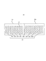
- FIG. 4 is a plan view of the braille display unit 10.
- the Braille display unit 10 includes a first Braille module 10x and a second Braille module 10y.
- the first Braille module 10x and the second Braille module 10y each include 32 movable pins 21.
- the Braille display unit 10 includes a total of 64 movable pins 21 in which the first Braille module 10x and the second Braille module 10y are continuously arranged.
- the Braille display unit 10 includes a total of eight unit Braille display units 22L, 22A to 22F, and 22R arranged side by side.
- the unit braille display portions 22A to 22F correspond to portions for displaying braille.
- the unit braille display units 22A to 22F each display eight brailles by raising and lowering eight movable pins 21 to form a convex shape.
- or 22F represent one character by one or two.
- the movable pin 21 arranged in the unit braille display portions 22A to 22F is referred to as a “first pin”.
- the unit braille display units 22L and 22R project the whole or a part of the movable pin 21 to display the presence / absence of characters or the appropriateness of positional relationship. Accordingly, the unit braille display units 22L and 22R appropriately capture the character string to be read by the camera 15 and guide the user to move the handheld Braille conversion device 1.
- the movable pin 21 arranged in the unit braille display portions 22L and 22R is referred to as a “second pin”.
- the display control unit 103 guides the moving direction of the handheld Braille converting device 1 (hereinafter simply referred to as “moving direction”) by raising the second pin. Specifically, in principle, the display control unit 103 raises the second pin located in the direction in which the user wants to correct the moving direction with respect to the finger placed on the handheld Braille conversion device 1 by the user. Lower the second pin located in the direction. At this time, the direction of the character string to be read is not changed. That is, the user corrects the moving direction of the handheld Braille conversion device 1 without changing the direction of the document or the like on which the character string to be read is written.
- a pin that does not protrude is indicated by “ ⁇ ”, and a pin that protrudes is indicated by “X in ⁇ ”.
- a square frame 80 in the figure indicates a range of characters or character strings (referred to as “braille target characters”) to be converted into braille.
- the “horizontal axis direction” refers to the long side direction of the rectangular frame 80 and coincides with the horizontal axis direction that defines the x-coordinate of the captured image described later with reference to FIG.
- the movable pins 21 arranged in two columns and four rows of the unit braille display portions 22L and 22R are identified by assigning a column number in order from the left on the drawing and by attaching a row number in order from the top.
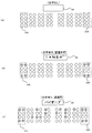
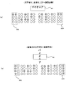
- FIG. 5A shows a state of the movable pin 21 when there is no braille target character. As shown in FIG. 5A, in this case, the display control unit 103 does not raise all the second pins.
- FIG. 5B shows the state of the movable pin 21 when the braille target characters are not in the Braille definition information.
- the display control unit 103 raises the second pins on the first and fourth lines corresponding to the four corners of the unit braille display unit 22L, and displays the unit braille display.
- the second pins of the first and fourth rows corresponding to the four corners of the portion 22R are raised.
- FIG. 5C shows the state of the movable pin 21 when the Braille target characters are in the Braille definition information and can be displayed in Braille.
- the display control unit 103 includes the braille target character “Pioneer” in the unit Braille display units 22A to 22F based on the Braille information supplied from the Braille conversion unit 102. Braille display with 1 pin. Specifically, according to the position of each character of the braille target character, the display control unit 103 displays “P” in braille on the unit braille display units 22A and 22B, and displays “I” on the unit braille display unit 22C. , “O” is displayed in braille on the unit braille display unit 22D, “d” is displayed in braille on the unit braille display unit 22E, and “a” is displayed in braille on the unit braille display unit 22F.
- the display control unit 103 raises the second pins of the first and fourth lines corresponding to the four corners of the unit braille display unit 22L, and the first line corresponding to the four corners of the unit braille display unit 22R. And the second pin in the fourth row is raised.
- FIG. 6A shows a state of the movable pin 21 when the braille target character corresponds to the end of the line.
- the display control unit 103 displays “Ionian”, which is a target character of Braille, in braille using the first pins of the unit braille display units 22A to 22D, respectively. Further, the display control unit 103 raises only the second pins at the four corners of the unit braille display unit 22L among the second pins of the unit braille display units 22L and 22R, so that the braille target character is the last of the line. To the user.
- FIG. 6B shows the state of the movable pin 21 when the braille target character corresponds to the leading edge of the line.
- the display control unit 103 displays the braille target character “PIO” in braille using the first pins included in the unit braille display units 22C to 22F according to the position. Further, the display control unit 103 raises only the second pins at the four corners of the unit braille display unit 22R among the second pins provided in the unit braille display units 22L and 22R, so that the braille target character is at the forefront of the line. Tell the user that there is.
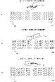
- FIG. 6C illustrates that the horizontal axis direction of the captured image is a predetermined angle clockwise with respect to the direction of the character string of the braille target character. (Hereinafter referred to as “angle ⁇ th”.)
- angle ⁇ th is 20 °, for example, and refers to an angle at which the character recognition unit 101 cannot accurately recognize the braille target character.
- the display control unit 103 raises the two second pins in the fourth row of the unit braille display unit 22L among all the movable pins 21, and the first row in the unit braille display unit 22R. Raise the two second pins. That is, the display control unit 103 raises the lower second pin of the unit braille display unit 22L to indicate that the left side of the handheld Braille conversion device 1 needs to be corrected downward, and the unit braille display unit 22R By raising the upper second pin, the right side of the handheld Braille conversion device 1 indicates that correction is required upward. Thereby, the display control unit 103 guides the user's operation to rotate the moving direction of the handheld Braille conversion device 1 counterclockwise in accordance with the character string. In response to this, the user moves the left side of the handheld Braille conversion device 1 downward and the right side upward, and as a result, corrects the moving direction of the handheld Braille conversion device 1 counterclockwise.
- FIG. 7 (a) shows that the horizontal axis direction of the captured image is counterclockwise by an angle ⁇ th or more with respect to the direction of the character string of the braille target character.
- the state of the movable pin 21 when the braille display cannot be performed due to the deviation is shown.
- the display control unit 103 raises the two second pins in the first row of the unit braille display unit 22L among all the movable pins 21, and the fourth row in the unit braille display unit 22R. Raise the two second pins.
- the display control unit 103 raises the second pin on the upper side of the unit braille display unit 22L to indicate that the left side of the handheld braille conversion device 1 needs to be corrected upward, and the unit braille display unit 22R By raising the second pin on the lower side, the right side of the handheld Braille conversion device 1 indicates that correction is required downward.
- the display control unit 103 guides the user's operation to rotate the handheld Braille conversion device 1 clockwise according to the character string.
- the user moves the left side of the handheld Braille conversion device 1 upward and the right side downward, and as a result, the movement direction of the handheld Braille conversion device 1 is corrected clockwise.
- FIG. 7B shows a range in which the horizontal axis direction of the captured image is within an angle ⁇ th with respect to the direction of the character string of the braille target character
- the state of the movable pin 21 when it is necessary to shift the left side of the handheld Braille converting device 1 upward by shifting counterclockwise is shown. It is assumed that the character recognition unit 101 correctly recognizes all braille target characters.
- the display control unit 103 displays braille target characters in braille using the first pins provided in the unit braille display units 22A to 22F. Further, the display control unit 103 raises two second pins of the first row among the second pins of the unit Braille display unit 22L, and also sets the first row and the second pin of the second pins of the unit Braille display unit 22R. A total of four second pins are raised in the fourth row. That is, the display control unit 103 raises the second pin on the upper side of the unit braille display unit 22L to indicate that the left side of the handheld Braille conversion device 1 needs to be corrected upward, while the unit braille display unit 22R.
- the display control unit 103 guides the user to move the handheld Braille conversion device 1 according to the character string. In response to this, the user corrects the left side of the handheld Braille conversion device 1 upward.
- FIG. 7C illustrates that the horizontal axis direction of the captured image is an angle ⁇ th clockwise with respect to the direction of the character string of the braille target character.
- the state of the movable pin 21 when it is necessary to shift the right side of the handheld Braille converting device 1 upward is shown. It is assumed that the character recognition unit 101 correctly recognizes all braille target characters.
- the display control unit 103 displays braille target characters in braille using the first pins provided in the unit braille display units 22A to 22F.
- the display control unit 103 raises a total of four second pins of the first and fourth rows among the second pins of the unit Braille display unit 22L, and also sets the second pins of the unit Braille display unit 22R.
- the two second pins in the first row are raised. That is, the display control unit 103 raises the second pin on the upper side of the unit braille display unit 22R to indicate that the right side of the handheld braille conversion device 1 needs to be corrected upward, while the unit braille display unit 22L.
- the display control unit 103 guides the user's operation to move the handheld Braille conversion device 1 according to the character string. In response to this, the user corrects the right side of the handheld Braille conversion device 1 upward.
- FIG. 8A shows an angle ⁇ th in which the horizontal axis direction of the captured image is clockwise with respect to the direction of the character string of the braille target character.
- the state of the movable pin 21 when it is necessary to shift the left side of the handheld Braille converting device 1 downward is shown. It is assumed that the character recognition unit 101 correctly recognizes all braille target characters.
- the display control unit 103 displays braille target characters in braille using the first pins of the unit braille display units 22A to 22F.
- the display control unit 103 raises two second pins of the fourth row among the second pins of the unit braille display unit 22L, and the first row and the second pin of the second pins of the unit braille display unit 22R. A total of four second pins are raised in the fourth row. That is, the display control unit 103 raises the lower second pin of the unit braille display unit 22L to indicate that the left side of the handheld braille conversion device 1 needs to be corrected downward, while the unit braille display unit By raising the upper and lower second pins of 22R, the right side of the handheld Braille conversion device 1 indicates that no correction is necessary. Thereby, the display control unit 103 guides the user to move the handheld Braille conversion device 1 according to the character string. In response to this, the user corrects the left side of the handheld Braille conversion device 1 downward.
- FIG. 8 (b) shows the angle of the horizontal axis direction of the captured image counterclockwise with respect to the direction of the character string of the braille target character
- the state of the movable pin 21 when it is necessary to shift the right side of the handheld Braille converting device 1 downward by shifting within the range of ⁇ th is shown. It is assumed that the character recognition unit 101 correctly recognizes all braille target characters.
- the display control unit 103 displays braille target characters in braille using the first pins of the unit braille display units 22A to 22F.
- the display control unit 103 raises a total of four second pins of the first and fourth rows among the second pins of the unit Braille display unit 22L, and also sets the second pins of the unit Braille display unit 22R. Among them, raise the 2nd pin of the 4th row. That is, the display control unit 103 raises the second pin below the unit braille display unit 22R to indicate that the right side of the handheld braille conversion device 1 needs to be corrected downward, while the unit braille display unit By raising the upper and lower second pins of 22L, the left side of the handheld Braille conversion device 1 indicates that no correction is necessary. Thereby, the display control unit 103 guides the user's operation to move the handheld Braille conversion device 1 according to the character string. In response to this, the user corrects the right side of the handheld Braille conversion device 1 downward.
- FIG. 8C shows a range in which the character can be recognized, and the entire handheld braille conversion device 1 is shifted upward with respect to the braille target character.
- the state of the movable pin 21 is shown. It is assumed that the character recognition unit 101 correctly recognizes all braille target characters.
- the display control unit 103 displays braille target characters in braille using the first pins of the unit braille display units 22A to 22F.
- the display control unit 103 raises two second pins in the fourth row among the second pins of the unit Braille display unit 22L, and at the fourth row among the second pins in the unit Braille display unit 22R. Raise the two second pins. That is, the display control unit 103 indicates that the whole handheld Braille converting device 1 needs to be corrected downward by raising the second pin below the unit Braille display units 22R and 22L.
- the display control unit 103 guides the user's operation to move the handheld Braille conversion device 1 according to the character string. In response to this, the user corrects the entire handheld Braille conversion device 1 downward.
- FIG. 9A shows a range in which the character can be recognized, and the entire handheld braille conversion device 1 is shifted downward with respect to the braille target character.
- the state of the movable pin 21 is shown. It is assumed that the character recognition unit 101 correctly recognizes all braille target characters.
- the display control unit 103 displays braille target characters in braille using the first pins of the unit braille display units 22A to 22F. Further, the display control unit 103 raises two second pins of the first row among the second pins of the unit braille display unit 22L, and also displays the second row of the second pins of the unit braille display unit 22R. Raise the two second pins. That is, the display control unit 103 indicates that the entire handheld Braille converting device 1 needs to be corrected upward by raising the second pin on the upper side of the unit Braille display units 22R and 22L. Thereby, the display control unit 103 guides the user's operation to move the handheld Braille conversion device 1 according to the character string. In response to this, the user corrects the entire handheld Braille converting device 1 upward.
- FIG. 9B shows the movable when the braille target character is vertically written and the character recognition unit 101 correctly recognizes all the braille target characters. The state of the expression pin 21 is shown.
- the display control unit 103 displays the braille target character in braille using the first pins of the unit braille display units 22A to 22F. Further, the display control unit 103 raises the four second pins of the first row among the second pins of the unit braille display unit 22L, and the second row of the second pins of the unit braille display unit 22R. Raise the four second pins. That is, when the braille target character is vertically written, the display control unit 103 arranges the second pins to be raised in the vertical direction. In this way, the display control unit 103 guides the user's operation to move the handheld Braille conversion device 1 according to the character string.
- the first row and the first column instead of the two second pins in the first row of the unit braille display portion 22L.
- Two second pins in the first row and the second row and first column are replaced with two second pins in the third row and first column and the fourth row and first column in place of the two second pins in the fourth row of the unit braille display portion 22L.
- the two second pins in the first row and second column and the second row and second column are replaced by the unit braille display portion.
- the two second pins in the fourth row of 22R are raised. By doing so, it is possible to prompt the user to perform an operation in accordance with the vertical writing and simultaneously correct the moving direction of the handheld Braille converting device 1.
- the first character to be read (hereinafter referred to as the character to be read)
- the character to be read The control of the movable pin 21 when guiding the direction of “initial” will be described with reference to FIG.
- the “document” refers to an information transmission medium in which a document to be read and other characters are described.
- FIG. 10A shows the state of the movable pin 21 when there is an initial in the upper left direction.
- FIG. 10B shows the state of the movable pin 21 when there is an initial in the upper right direction.
- FIG. 10C shows the state of the movable pin 21 when there is an initial in the lower left direction.
- FIG. 10D shows the state of the movable pin 21 when there is an initial in the lower right direction.
- the subsequent states of the unit braille display portions 22A to 22F in FIGS. 10A to 10D are merely examples, and are not directly related to the guidance of the direction of the initial characters.
- the display control unit 103 raises the second pin located in the direction in which the user wants to correct the moving direction and the second pin located in the other direction with respect to the finger placed on the handheld Braille conversion device 1 by the user. Lower.
- the display control unit 103 includes the unit braille display unit 22L among the second pins provided in the unit braille display units 22L and 22R. A total of four second pins in the first row and the second row are set up. Also, as shown in FIG.
- the display control unit 103 selects the first of the unit braille display unit 22R among the second pins provided in the unit braille display units 22L and 22R. A total of four second pins in the row and the second row are raised. Further, as shown in FIG. 10C, when there is an initial character in the lower left direction, the display control unit 103 sets the third of the unit braille display unit 22L among the second pins provided in the unit braille display units 22L and 22R. A total of four second pins in the row and the fourth row are raised. Further, as shown in FIG.
- the display control unit 103 when there is an initial character in the lower right direction, the display control unit 103 includes the second pin of the unit Braille display unit 22R among the second pins provided in the unit Braille display units 22L and 22R. A total of four second pins in the third and fourth rows are raised.
- the handheld Braille conversion device 1 acquires a captured image representing the entire set of character strings described in the document (hereinafter simply referred to as “the entire document”) from the camera 15. Then, the initial part is estimated from the captured image. This will be described with reference to FIG. FIG. 11 shows an example of a captured image showing the entire document.
- the character recognition unit 101 specifies a range in which each character string of the entire document is described. For example, the character recognizing unit 101 first identifies the width boundary of each character string in the document as indicated by the vertical line in FIG.
- the character recognizing unit 101 detects that the boundary of the first line out of the left boundary of each character string is shifted by the indentation, and the second and subsequent lines are aligned or within the predetermined difference. Check that the points are on a straight line and the right boundary of each character string is scattered in each line. The predetermined difference is set to a value less than a space corresponding to indentation, for example. Then, the character recognition unit 101 determines that the initial part is the leftmost character on the first line from the above two points. Then, as shown in FIG. 10A, the display control unit 103 guides the user's operation to move the handheld Braille converting device 1 to the upper left.
- each character string of the entire document has an angle ⁇ r of 180 °, that is, shifted upside down or an absolute angle ⁇ r.
- the value may be greater than or equal to the angle ⁇ th.
- the display control unit 103 appropriately controls the second pin according to the specific example 6 in FIG. 6C and the specific example 7 in FIG. Thereby, the display control unit 103 can guide the user's operation, and can match each character string with the horizontal axis of the captured image.
- the display control unit 103 ends the initial direction guidance.
- the handheld Braille conversion device 1 can appropriately guide the user's operation using the second pin in various cases.
- the character recognizing unit 101 determines the average character width (hereinafter referred to as “character length Nr”) of characters to be read from the character string length Lr and the number of characters (hereinafter referred to as “character number Nr”). Simply referred to as “average character width Wr”).
- the Braille conversion unit 102 refers to the number of unit Braille display units 22 (hereinafter referred to as “Braille cell number Ns”) necessary for expressing the Braille when the character string is converted into Braille. calculate. Then, when the handheld Braille converting device 1 moves, the display control unit 103 displays the Braille of the character string at an average interval based on the average character width Wr and the Braille cell number Ns.
- FIG. 12 shows an example of a captured image acquired from the camera 15.
- the captured image 50 shown in FIG. 12 is composed of a plurality of horizontally written character strings.
- the relative position on the captured image 50 is also referred to as a position on the horizontal axis (also referred to as “x coordinate”) with the upper left corner as the origin and a position on the vertical axis (also referred to as “y coordinate”). .)) Is expressed as “(x, y)”.
- x indicates an x-coordinate value (0 ⁇ x ⁇ 1000)
- y indicates a y-coordinate value (0 ⁇ y ⁇ 1000).
- the character recognition unit 101 recognizes a plurality of character strings 70 indicated by a broken-line square frame from the captured image 50. Then, the character recognition unit 101 calculates each position Pr, angle ⁇ r, and character string length Lr of the character string 70. Here, the character recognizing unit 101 acquires a set of the coordinates of the upper left corner and the coordinates of the lower right corner of each character string 70 as the position Pr of each character string 70. For example, the character recognition unit 101 specifies the absolute value of the difference between the x coordinate of the left boundary and the x coordinate of the right boundary of each character string as the character string length Lr.
- the character recognition unit 101 selects a character string 70 including the central coordinates (500, 500) located at the center of the captured image 50 from the plurality of recognized character strings 70, or a character string 70 closest to the central coordinates. It is specified as a character string to be braille.
- the character recognizing unit 101 calls the character string 70x surrounded by a solid line frame including the center coordinates as a character string to be braille (hereinafter referred to as a “braille target character string”). )). That is, the character string 70y surrounded by the broken line frame is not a braille target character string.
- the Braille conversion unit 102 counts the number of characters Nr of the character string 70x, which is the Braille target character string, and sets a value obtained by dividing the character string length Lr of the character string 70x by the character number Nr as an average character width Wr. That is, the Braille conversion unit 102 calculates the average character width Wr by the following equation (1).
- FIG. 13 is a conceptual diagram showing a process of calculating the number of braille cells Ns from the character string 70x.
- the first line in FIG. 13 shows the character string 70x displayed in the captured image 50 as it is.
- the character string on the first line has 26 characters including Kanji. That is, the number of characters Nr is 26.
- the second line of FIG. 13 shows a character string obtained by converting (kana conversion) kanji in the character string 70x.
- the second line has 31 characters.
- the third line in FIG. 13 lists the number of unit braille display portions 22 (number of braille cells) necessary for expressing each character in the second line in braille.
- the number of braille cells of a kana character including numbers and dakuten and uppercase alphabets is 2, and the number of braille cells of other characters is 1.
- the Braille conversion unit 102 calculates the sum of the number of Braille cells of each character, so that the number of Braille cells Ns necessary for displaying the character string 70x in Braille is 45. Is identified.
- the Braille conversion unit 102 specifies a character (hereinafter referred to as “central character”) located at the center of the character string 70x that is the Braille target character string. Specifically, the Braille conversion unit 102 specifies the position of the coordinates (500, 500) located at the center of the captured image, that is, the character in the character string 70x closest to the intersection of the broken lines in FIG. 13 as the central character. . That is, the Braille conversion unit 102 specifies the character “U” in the broken line frame 71A shown in FIG. 13 as the central character.
- the display control unit 103 displays the characters that can be displayed in braille by the 6 cells of the unit braille display units 22A to 22F including the central character. Specifically, the display control unit 103 displays the characters “Kudokushi” for 6 cells in the broken line frame 71B shown in FIG. 13 in braille using the unit braille display units 22A to 22F.
- the display control unit 103 determines a character string to be displayed in braille by a method different from the above-described processing. This will be described with reference to FIG.
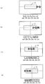
- FIG. 14 is a diagram showing the position of the braille target character string composed of “kana strings” and the unit braille display sections 22A to 22F to be used. From FIG. 14A to FIG. 14D, the handheld Braille converting device 1 is gradually moving in the right direction. Here, it is assumed that the number of necessary braille cells for “Kanaretsu” corresponding to the kana column is one per character.
- a broken line frame 72 indicates the existence range of characters to be braille (hereinafter referred to as “braille target range”).
- a part of the braille target character string is displayed at the right end of the captured image.
- the display control unit 103 determines that the braille target character string does not exist within the braille target range indicated by the broken line frame 72, and does not perform the braille display by the unit braille display units 22A to 22F.
- the “kana” portion of the braille target character string exists within the braille target range.
- the display control unit 103 displays “Kana” in “Kana” obtained by converting “Kana” based on the position of “Kana” in the Braille target range using the unit Braille display unit 22E in Braille. "Is displayed in braille by the unit braille display 22F.
- the Braille target character string existing in the Braille target range when a character that requires two unit Braille display parts to express one kana is included (for example, a character with muddy sound), Only the first character may be displayed in braille by the unit braille display units 22E and 22F.
- the display control unit 103 displays the “Kana” in the “Kana string” obtained by converting the “Kana string” into the unit Braille display unit 22B based on the position occupied by each character of the “Kana string” in the Braille target position 72. Is displayed in braille, “na” is displayed in braille by the unit braille display 22C, “re” is displayed in braille by the unit braille display 22D, and “tsu” is displayed in braille by the unit braille display 22E.
- the display control unit 103 causes the unit braille display unit 22A to display “na” among “naretsu” obtained by kana-converting the “na string” based on the position occupied by each character of “na string” in the braille target range.
- Braille is displayed, “Re” is displayed in Braille by the unit Braille display unit 22B, and “T” is displayed in Braille by the unit Braille display unit 22C.
- Braille target character string existing within the Braille target range if a character that requires two unit braille display parts to represent one kana is included, only the second character is used as the unit. Braille is displayed by the Braille display unit 22A.
- the display control unit 103 displays only the characters present in the braille target range in braille. Further, the display control unit 103 changes the unit Braille display unit 22 that displays the character in Braille based on the position of the character in the Braille target range.
- the character recognition unit 101 acquires captured images from the camera 15 at regular intervals, and specifies the braille target character string by executing the above-described processing. Then, the character recognition unit 101 determines whether or not the specified braille target character string is the same as the previously specified braille target character string.
- the character recognition unit 101 repeats the above-described processing from the beginning again. That is, the character recognizing unit 101 specifies a character string in a new captured image and starts processing for acquiring information such as the position Pr.
- the braille target character string is displayed over the entire width of the captured image 50, the braille target character string is partially changed even if it is moved by one character. Therefore, in this case, the character recognition unit 101 considers that the braille target character string has changed.
- the braille conversion unit 102 determines the position Pr (hereinafter referred to as “position Pr1”) of the braille target character string of the previous captured image and the braille target character string of the new captured image.
- the deviation (hereinafter referred to as “movement width”) of the position Pr (hereinafter referred to as “position Pr2”) is calculated.
- the “previous captured image” refers to a captured image corresponding to the current braille display.
- the Braille conversion unit 102 shifts the Braille display based on the average character width Wr and the Braille cell number Ns according to the movement width.
- FIG. Fig.15 (a) is an example of the figure which shows the positional relationship of the character string before and behind a movement.
- the character string before movement is represented by white characters
- the character string after movement is represented by bold characters.
- the movement width in the horizontal axis direction is represented as “dx”
- the movement width in the vertical axis direction is represented as “dy”.
- the Braille conversion unit 102 calculates the movement width dx and the movement width dy based on the position Pr1 and the position Pr2. Then, the Braille conversion unit 102 multiplies the average character width Wr by a value (Nr / Ns) obtained by dividing the moving width dx and the number of characters Nr by the number of Braille cells Ns (hereinafter referred to as “average cell”). Width Ws "). That is, the average cell width Ws satisfies the following formula (2).
- the display control unit 103 shifts the braille display by one unit braille display unit 22. It slides in the direction (in the case of FIG. 15A, the right direction) and is displayed.
- the predetermined difference is determined in advance based on, for example, experiments. That is, for example, when the braille display is slid to the right by one unit braille display unit 22, the display control unit 103 displays the braille displays of the unit braille display units 22A to 22E by the unit braille display units 22B to 22F, respectively.
- the unit braille display 22A displays braille corresponding to the new character.
- the display control part 103 can display the braille of a braille object character string at an average space
- the display control unit 103 guides the user's operation with the second pin as shown in FIG. 8C or FIG. 9A, for example.
- the moving width dx is smaller than the average cell width Ws, the braille display is not changed (does not slide), the moving width dx is added to the next moving width dx, and the next moving width dx is finally slid on the braille display. After that, make the movement width.
- FIG. 15B is an example of a diagram showing the positional relationship between the braille target character strings before and after movement.
- the braille target character string before movement is represented by white characters
- the braille target character string after movement is represented by bold characters.
- the movement width in the horizontal axis direction of the leading character in the braille target character string before and after the movement is expressed as “dx1”, and the horizontal axis of the partially matched character string “technical stand”
- the movement width in the direction is expressed as “dx2”
- the movement width in the vertical axis direction is expressed as “dy”.
- the character recognition unit 101 calculates movement widths dx1, dx2, and dy, respectively.
- the Braille conversion unit 102 calculates a value (dx2 / Ws) obtained by dividing the movement width dx2 by the average cell width Ws.
- the display control unit 103 slides the braille display in a direction shifted by the number of unit braille display units 22 corresponding to the above-described value (dx2 / Ws) (rightward in the case of FIG. 15B). Redisplay. Thereby, even in this case, the display control unit 103 can display the Braille of the Braille target character string at an average interval.
- the Braille conversion unit 102 may round up to an integer value when rounding or other predetermined cases.
- the display control unit 103 guides the user's operation with the second pin as shown in FIG. 8C or FIG. 9A, for example. .
- the predetermined value described above is set in advance by experiments or the like. Further, the display control unit 103 grasps the position of the character currently displayed in Braille among the Braille target character strings based on the movement width dx1, and displays the appropriateness of the positional relationship as shown in FIG. 6B, for example. .
- the character recognition unit 101 re-executes all processes from the process of specifying the braille target character string.
- FIG. 16 is a flowchart of the braille conversion process.
- the user places the handheld Braille conversion device 1 on a printed matter or the like on which characters to be displayed in Braille are present, and turns on the switch of the Braille conversion processing (Step S1).
- the camera 15 captures a predetermined range around the handheld Braille conversion device 1 (step S2), and transmits the captured image to the character recognition unit 101.
- the character recognition unit 101 determines whether or not a character exists in the received captured image (step S3). If there is a character in the captured image (step S3; Yes), the display control unit 103 displays the positional relationship suitability by the second pin (step S4). For example, the display control unit 103 notifies the user of the initial direction by performing a positional relationship suitability display as shown in FIG. In another example, when the character string is vertically written, the display control unit 103 displays the appropriateness of the positional relationship shown in FIG. 9B to notify the user that the character string is vertically written. Further, when the character string is deviated, the display control unit 103 displays the appropriateness of the positional relationship as shown in FIG. 6C and notifies the user of the deviating direction.
- step S3 when there is no character in the captured image (step S3; No), the display control unit 103 clears all the braille display and the positional relationship suitability display (step S5). That is, the display control unit 103 controls the first pin and the second pin so as to be in the state shown in FIG.
- the character recognition unit 101 specifies a braille target character string (step S5). Specifically, the character recognition unit 101 identifies a character string located at the center of the captured image from a plurality of character strings in the captured image as a braille target character string.
- the braille conversion unit 102 calculates the average character width Wr and the number of braille cells Ns of the braille target character string (step S7). Specifically, the Braille conversion unit 102 calculates the average character width Wr based on Expression (1). Further, as shown in FIG. 13, the Braille conversion unit 102 calculates the necessary number of Braille cells Ns after converting the kanji of the Braille target character string into kana.
- the display control unit 103 performs braille display for 6 cells before and after the central character (step S8).
- the central character indicates the character in the braille target character string that is closest to the center of the captured image.
- the character recognition unit 101 determines whether or not the apparatus has moved based on the change in the captured image (step S9). Then, when the apparatus has moved (step S9; Yes), the display control unit 103 executes the process of step S10. Specifically, when the braille target character strings are identical or partially coincident before and after the movement, the Braille conversion unit 102 calculates the movement width on the horizontal axis and calculates the average character width as shown in Expression (2). An average cell width Ws is calculated based on Wr and the number of braille cells Ns. And the display control part 103 specifies the number of the unit braille display parts 22 which should be slid based on the said movement width and the average cell width Ws, and displays braille again.
- the display control part 103 can display the braille of a braille object character string at an average space
- the handheld Braille conversion device 1 re-executes the processes of steps S4 to S8.
- step S9 when the apparatus is not moving (step S9; No), the display control unit 103 continues the display (step S11).
- step S12 determines whether or not the switch is turned off.
- step S12 determines whether or not the switch is turned off.
- the switch is not OFF (step S12; No)
- the process returns to step S2 and repeats steps S2 to S11. If the switch is turned off (step S12; Yes), the process is terminated.
- the display control unit 103 may quickly vibrate up and down when raising the second pin. Thereby, the display control unit 103 can prevent the user from confusion between the braille display by the first pin and the positional relationship suitability display by the second pin.
- the first braille module 10x and the second braille module 10y each include four unit braille display sections 22, but the present invention is not limited to this. Specifically, the number is most easily recognized by the fingertip for the user. Even in this case, the display control unit 103 uses any two unit braille display units 22 as the second pins.
- one unit Braille display unit 22 is composed of a total of eight movable pins 21 with two columns and four rows. However, the present invention is not limited to this. It may be configured by a single movable pin 21.
- the characters of the printed matter are converted to Braille, but the present invention is not limited to this. Even if it is not a printed character, it can be converted to Braille if it can be photographed by the camera.
- the display control unit 103 is basically positioned in the direction in which the user wants to correct the moving direction with respect to the finger placed on the handheld Braille conversion device 1. While raising 2 pins, the 2nd pin located in the other direction was lowered. However, the method to which the present invention is applicable is not limited to this. Instead of this, the display control unit 103 may cause the second pin to function as an obstacle. That is, in principle, the display control unit 103 lowers the second pin located in the direction in which the user wants to correct the moving direction with respect to the finger placed on the handheld Braille conversion device 1 and is located in the other direction. The second pin may be raised. Also by this, the handheld Braille conversion device 1 can appropriately guide the user's operation. In another example, the display control unit 103 may vibrate these instead of raising and lowering the first pin and the second pin.
Landscapes
- Engineering & Computer Science (AREA)
- Theoretical Computer Science (AREA)
- Physics & Mathematics (AREA)
- General Physics & Mathematics (AREA)
- Health & Medical Sciences (AREA)
- Multimedia (AREA)
- Computer Vision & Pattern Recognition (AREA)
- Audiology, Speech & Language Pathology (AREA)
- General Health & Medical Sciences (AREA)
- Business, Economics & Management (AREA)
- Educational Administration (AREA)
- Educational Technology (AREA)
- User Interface Of Digital Computer (AREA)
- Character Input (AREA)
- Character Discrimination (AREA)
Abstract
Description
まず、本発明の本実施例に係るハンドヘルド点字変換装置1の構成について図1乃至図4を用いて説明する。
図1は、本発明の本実施例に係るハンドヘルド点字変換装置1を模式的に表した図である。図示のように、ハンドヘルド点字変換装置1は、点字表示部10、CPU11、RAM12、ROM13、電源14、カメラ15、レンズ16、照明用LED17を備える。
図3は、本実施例のハンドヘルド点字変換装置1の機能構成を示すブロック図の一例である。これらの機能は、図1に示す構成要素により実現される。
次に、点字表示部10の構成について図4を用いて説明する。図4は、点字表示部10の平面図を示す。
次に、表示制御部103が実行する第2ピンの制御方法について説明する。概略的には、表示制御部103は、第2ピンを立たせることで、ハンドヘルド点字変換装置1の移動方向(以後、単に「移動方向」と呼ぶ。)を誘導する。具体的には、表示制御部103は、原則的に、利用者がハンドヘルド点字変換装置1に置いた指に対して、移動方向を修正したい方向に位置する第2ピンを立たせると共に、他の方向に位置する第2ピンを下げる。なお、この際、読み取りの対象となる文字列の方向は変わらないものとする。つまり、利用者は、読み取りの対象となる文字列が記載された書類などの方向は変えず、ハンドヘルド点字変換装置1の移動方向を修正する。
図5(a)は、点字対象文字がない場合の可動式ピン21の状態を示す。図5(a)に示すように、この場合、表示制御部103は、全ての第2ピンを立たせない。
図5(b)は、点字対象文字が点字定義情報にない場合の可動式ピン21の状態を示す。図5(b)に示すように、表示制御部103は、この場合、単位点字表示部22Lの四隅に相当する第1行目及び第4行目の第2ピンを立たせると共に、単位点字表示部22Rの四隅に相当する第1行目及び第4行目の第2ピンを立たせる。
図5(c)は、点字対象文字が点字定義情報にあり、点字表示可能な場合の可動式ピン21の状態を示す。図5(c)に示すように、この場合、表示制御部103は、点字対象文字「パイオニア」を、点字変換部102から供給された点字情報に基づき、単位点字表示部22A乃至22Fが備える第1ピンで点字表示する。具体的には、表示制御部103は、点字対象文字の各文字の位置に従い、「パ」を単位点字表示部22A、22Bで点字表示し、「イ」を単位点字表示部22Cで点字表示し、「オ」を単位点字表示部22Dで点字表示し、「ニ」を単位点字表示部22Eで点字表示し、「ア」を単位点字表示部22Fでそれぞれ点字表示する。
図6(a)は、点字対象文字が行の最後に相当する場合の可動式ピン21の状態を示す。図6(a)に示すように、この場合、表示制御部103は、点字対象文字である「イオニア」をそれぞれ単位点字表示部22A乃至22Dの第1ピンで点字表示している。また、表示制御部103は、単位点字表示部22L、22Rの第2ピンのうち、単位点字表示部22Lの四隅の第2ピンのみを立たせることで、点字対象文字が行の最後であることを利用者に知らせる。
図6(b)は、点字対象文字が行の最先端に相当する場合の可動式ピン21の状態を示す。図6(b)に示すように、この場合、表示制御部103は、点字対象文字「パイオ」を、その位置に従い、単位点字表示部22C乃至22Fが備える第1ピンで点字表示する。また、表示制御部103は、単位点字表示部22L、22Rが備える第2ピンのうち、単位点字表示部22Rの四隅の第2ピンのみを立たせることで、点字対象文字が行の最先端であることを利用者に知らせる。
図6(c)は、撮像画像の横軸方向が、点字対象文字の文字列の方向に対して時計回りに所定角度(以後、「角度Θth」と呼ぶ。)以上ずれていることにより、点字表示ができない場合の可動式ピン21の状態を示す。ここで、角度Θthとは、例えば20°であり、文字認識部101が点字対象文字を正確に認識することができない角度を指す。この場合、表示制御部103は、全ての可動式ピン21のうち、単位点字表示部22Lの第4行目の2つの第2ピンを立たせると共に、単位点字表示部22Rの第1行目の2つの第2ピンを立たせる。即ち、表示制御部103は、単位点字表示部22Lの下側の第2ピンを立たせることにより、ハンドヘルド点字変換装置1の左側は下方へ修正が必要であることを示し、単位点字表示部22Rの上側の第2ピンを立たせることにより、ハンドヘルド点字変換装置1の右側は上方へ修正が必要であることを示す。これにより、表示制御部103は、文字列に合わせてハンドヘルド点字変換装置1の移動方向を反時計回りに回転させるように利用者の操作を誘導する。これに応じて、利用者はハンドヘルド点字変換装置1の左側を下方へ、右側を上方へ移動させ、その結果、ハンドヘルド点字変換装置1の移動方向を反時計回りに修正することになる。
図7(a)は、撮像画像の横軸方向が、点字対象文字の文字列の方向に対して角度Θth以上反時計回りにずれていることにより、点字表示ができない場合の可動式ピン21の状態を示す。この場合、表示制御部103は、全ての可動式ピン21のうち、単位点字表示部22Lの第1行目の2つの第2ピンを立たせると共に、単位点字表示部22Rの第4行目の2つの第2ピンを立たせる。即ち、表示制御部103は、単位点字表示部22Lの上側の第2ピンを立たせることにより、ハンドヘルド点字変換装置1の左側は上方へ修正が必要であることを示し、単位点字表示部22Rの下側の第2ピンを立たせることにより、ハンドヘルド点字変換装置1の右側は下方へ修正が必要であることを示す。これにより、表示制御部103は、文字列に合わせてハンドヘルド点字変換装置1を時計回りに回転させるように利用者の操作を誘導する。これに応じて、利用者はハンドヘルド点字変換装置1の左側を上方へ、右側を下方へ移動させ、その結果、ハンドヘルド点字変換装置1の移動方向を時計回りに修正することになる。
図7(b)は、撮像画像の横軸方向が、点字対象文字の文字列の方向に対して角度Θth以内の範囲で反時計回りにずれていることにより、ハンドヘルド点字変換装置1の左側を上方にずらす必要がある場合の可動式ピン21の状態を示す。なお、文字認識部101は、全ての点字対象文字を正しく認識したとする。
図7(c)は、撮像画像の横軸方向が、点字対象文字の文字列の方向に対して時計回りに角度Θth以内の範囲でずれていることにより、ハンドヘルド点字変換装置1の右側を上方にずらす必要がある場合の可動式ピン21の状態を示す。なお、文字認識部101は、全ての点字対象文字を正しく認識したとする。
図8(a)は、撮像画像の横軸方向が、点字対象文字の文字列の方向に対して時計回りに角度Θth以内の範囲でずれていることにより、ハンドヘルド点字変換装置1の左側を下方にずらす必要がある場合の可動式ピン21の状態を示す。なお、文字認識部101は、全ての点字対象文字を正しく認識したとする。
図8(b)は、撮像画像の横軸方向が、点字対象文字の文字列の方向に対して反時計回りに角度Θth以内の範囲でずれていることにより、ハンドヘルド点字変換装置1の右側を下方にずらす必要がある場合の可動式ピン21の状態を示す。なお、文字認識部101は、全ての点字対象文字を正しく認識したとする。
図8(c)は、文字認識可能な範囲で、点字対象文字に対してハンドヘルド点字変換装置1全体が上方にずれている場合の可動式ピン21の状態を示す。なお、文字認識部101は、全ての点字対象文字を正しく認識したとする。
図9(a)は、文字認識可能な範囲で、点字対象文字に対してハンドヘルド点字変換装置1全体が下方にずれている場合の可動式ピン21の状態を示す。なお、文字認識部101は、全ての点字対象文字を正しく認識したとする。
図9(b)は、点字対象文字が縦書きであり、かつ、文字認識部101が全ての点字対象文字を正しく認識した場合の可動式ピン21の状態を示す。
次に、文書にハンドヘルド点字変換装置1を乗せて利用者の指示により又は自動的に点字処理を開始する場合であって、当該文書の最初に読むべき文字(以後、「頭文字」とも呼ぶ。)の方向を誘導するときの可動式ピン21の制御について図10を用いて説明する。ここで、「文書」とは、読み取る対象となる文書その他文字が記載された情報伝達媒体を指す。
次に、文字認識方法及び点字変換方法について説明する。概略的には、文字認識部101は、読み取る対象となる文字列の文字列長Lr及び文字数(以後、「文字数Nr」と呼ぶ。)から当該文字列を構成する各文字の平均文字幅(以後、単に「平均文字幅Wr」と呼ぶ。)を計算する。次に、点字変換部102は、当該文字列が点字に変換された場合の当該点字を表現するのに必要な単位点字表示部22の数(以後、「点字セル数Ns」と呼ぶ。)を計算する。そして、表示制御部103は、ハンドヘルド点字変換装置1が移動した場合、平均文字幅Wrと点字セル数Nsとに基づき、当該文字列の点字を平均的な間隔で表示する。
そして、点字変換部102は、文字列70xの各文字を点字に変換した後、文字列70xの点字セル数Nsを算出する。この処理について図13を用いて説明する。図13は、文字列70xから点字セル数Nsを算出する処理を示す概念図である。
そして、移動幅dxが平均セル幅Wsより大きい又は所定差以内であると点字変換部102が判断した場合、表示制御部103は、点字表示を単位点字表示部22の1個分だけ、ずれた方向(図15(a)の場合、右方向)にスライドして表示する。上述の所定差は、例えば実験等に基づき予め定められる。即ち、表示制御部103は、例えば点字表示を右方向に単位点字表示部22の1個分だけスライドする場合、単位点字表示部22A乃至22Eの点字表示をそれぞれ単位点字表示部22B乃至22Fにより表示し、単位点字表示部22Aでは新たな文字に対応する点字を表示する。これにより、表示制御部103は、点字対象文字列の点字を平均的な間隔で表示することができる。これに加え、移動幅dyが所定値以上の場合、表示制御部103は、例えば図8(c)又は図9(a)に示すように、第2ピンにより利用者の操作を誘導する。なお、移動幅dxが平均セル幅Wsより小さい場合、点字表示を変えない(スライドしない)が移動幅dxを、次回の移動幅dxに加算し、次回の移動幅dxが最後に点字表示をスライドしてからの移動幅になるようにする。
次に、本実施例による点字変換処理について図16を参照して説明する。この処理は、図1に示すシステムコントローラ19が予め用意されたプログラムを実行することにより実現される。図16は点字変換処理のフローチャートである。
次に、本実施例の変形例について説明する。以下の変形例は、任意に組み合わせて上述の実施例に適用することができる。
10 点字表示部
11 CPU
14 電源
15 カメラ
16 レンズ
17 照明用LED
19 システムコントローラ
101 文字認識部
102 点字変換部
103 表示制御部
Claims (11)
- ユーザが片手で保持した状態で移動させることが可能なハンドヘルド点字変換装置であって、
前記ハンドヘルド点字変換装置を保持している手の少なくとも一本の指が接触可能な位置に配置され、点字を表示する点字表示部と、
前記ハンドヘルド点字変換装置周辺の所定範囲を撮影する撮影手段と、
前記撮影手段の撮影画像に存在する文字の有無を検知し、存在する文字を認識する文字認識手段と、
前記文字認識手段が認識した文字の一部又は全部を点字に変換する点字変換手段と、
前記点字変換手段が変換した点字を前記点字表示部に表示させる表示制御手段と、を備え、
前記点字表示部は、各々が1つの点字に対応する複数の単位点字表示部を有し、
前記単位点字表示部は、複数の可動式の部材を有し、
前記表示制御手段は、前記単位点字表示部のうち一部の単位点字表示部が有する部材を動作させることにより前記撮影画像に存在する文字又は文字列に対する前記ハンドヘルド点字変換装置の位置関係の適否を表示すると共に、前記一部の単位点字表示部以外の単位点字表示部が有する部材を動作させることにより点字を表示することを特徴とするハンドヘルド点字変換装置。 - 前記単位点字表示部は並べて設置され、
表示制御部は、前記単位点字表示部のうち両端に位置する単位点字表示部が有する部材を動作させることにより、前記撮影画像に存在する文字又は文字列に対する前記ハンドヘルド点字変換装置の位置関係の適否を表示することを特徴とする請求項1に記載のハンドヘルド点字変換装置。 - 前記表示制御手段は、前記一部の単位点字表示部が有する部材を動作させることにより、前記ハンドヘルド点字変換装置の位置が前記撮影画像に存在する文字又は文字列に対していずれの方向にずれているかを示すことを特徴とする請求項1に記載のハンドヘルド点字変換装置。
- 前記表示制御手段は、前記一部の単位点字表示部が有する部材を動作させることにより、前記撮影画像に存在する文字の有無を示すことを特徴とする請求項1乃至3のいずれか一項に記載のハンドヘルド点字変換装置。
- 前記表示制御手段は、前記一部の単位点字表示部が有する部材を動作させることにより、前記撮影画像に存在する文字列が横書きであるか縦書きであるかを示すことを特徴とする請求項1乃至4のいずれか一項に記載のハンドヘルド点字変換装置。
- 前記表示制御手段は、前記一部の単位点字表示部が有する部材を動作させることにより、前記撮影画像に存在する文字列の頭文字の方向を示すことを特徴とする請求項1乃至5のいずれか一項に記載のハンドヘルド点字変換装置。
- 前記表示制御手段は、前記一部の単位点字表示部が有する部材を昇降させて凸形状を形成したりしなかったりする動作を振動させて行うことにより前記位置関係の適否を表示すると共に、前記一部の単位点字表示部以外の単位点字表示部が有する部材を昇降させて凸形状を形成したりしなかったりすることで点字を表示することを特徴とする請求項1乃至6のいずれか一項に記載のハンドヘルド点字変換装置。
- 前記点字変換手段は、点字表示の対象となる文字列を構成する各文字の平均文字幅を算出すると共に、当該文字列に相当する点字の数を算出し、
前記表示制御手段は、前記ハンドヘルド点字変換装置が移動した場合、前記平均文字幅と前記点字の数とに基づき、点字の表示を変更することを特徴とする請求項1乃至7に記載のハンドヘルド点字変換装置。 - ユーザが片手で保持した状態で移動させることが可能であり、保持している手の少なくとも一本の指が接触可能な位置に配置されて点字を表示する点字表示部を備えるハンドヘルド点字変換装置が実行する点字変換方法であって、
前記ハンドヘルド点字変換装置周辺の所定範囲を撮影する撮影工程と、
前記撮影工程の撮影画像に存在する文字の有無を検知し、存在する文字を認識する文字認識工程と、
前記文字認識工程が認識した文字の一部又は全部を点字に変換する点字変換工程と、
前記点字変換工程が変換した点字を前記点字表示部に表示させる表示制御工程と、を備え、
前記点字表示部は、各々が1つの点字に対応する複数の単位点字表示部を有し、
前記単位点字表示部は、複数の可動式の部材を有し、
前記表示制御工程は、前記単位点字表示部のうち一部の単位点字表示部が有する部材を動作させることにより前記撮影画像に存在する文字又は文字列に対する前記ハンドヘルド点字変換装置の位置関係の適否を表示すると共に、前記一部の単位点字表示部以外の単位点字表示部が有する部材を動作させることにより点字を表示することを特徴とする点字変換方法。 - ユーザが片手で保持した状態で移動させることが可能であり、保持している手の少なくとも一本の指が接触可能な位置に配置されて点字を表示する点字表示部を備えるハンドヘルド点字変換装置により実行される点字変換プログラムであって、
前記ハンドヘルド点字変換装置周辺の所定範囲を撮影する撮影手段と、
前記撮影手段の撮影画像に存在する文字の有無を検知し、存在する文字を認識する文字認識手段と、
前記文字認識手段が認識した文字の一部又は全部を点字に変換する点字変換手段と、
前記点字変換手段が変換した点字を前記点字表示部に表示させる表示制御手段、として前記ハンドヘルド点字変換装置を機能させ、
前記点字表示部は、各々が1つの点字に対応する複数の単位点字表示部を有し、
前記単位点字表示部は、複数の可動式の部材を有し、
前記表示制御手段は、前記単位点字表示部のうち一部の単位点字表示部が有する部材を動作させることにより前記撮影画像に存在する文字又は文字列に対する前記ハンドヘルド点字変換装置の位置関係の適否を表示すると共に、前記一部の単位点字表示部以外の単位点字表示部が有する部材を動作させることにより点字を表示することを特徴とする点字変換プログラム。 - 請求項10に記載の点字変換プログラムを記憶したことを特徴とする記憶媒体。
Priority Applications (3)
| Application Number | Priority Date | Filing Date | Title |
|---|---|---|---|
| JP2011540377A JPWO2011058656A1 (ja) | 2009-11-16 | 2009-11-16 | ハンドヘルド点字変換装置、点字変換方法、点字変換プログラム及び記憶媒体 |
| US13/509,468 US20120236134A1 (en) | 2009-11-16 | 2009-11-16 | Handheld braille converting device, braille converting method, braille converting program, and storage medium |
| PCT/JP2009/069439 WO2011058656A1 (ja) | 2009-11-16 | 2009-11-16 | ハンドヘルド点字変換装置、点字変換方法、点字変換プログラム及び記憶媒体 |
Applications Claiming Priority (1)
| Application Number | Priority Date | Filing Date | Title |
|---|---|---|---|
| PCT/JP2009/069439 WO2011058656A1 (ja) | 2009-11-16 | 2009-11-16 | ハンドヘルド点字変換装置、点字変換方法、点字変換プログラム及び記憶媒体 |
Publications (1)
| Publication Number | Publication Date |
|---|---|
| WO2011058656A1 true WO2011058656A1 (ja) | 2011-05-19 |
Family
ID=43991335
Family Applications (1)
| Application Number | Title | Priority Date | Filing Date |
|---|---|---|---|
| PCT/JP2009/069439 Ceased WO2011058656A1 (ja) | 2009-11-16 | 2009-11-16 | ハンドヘルド点字変換装置、点字変換方法、点字変換プログラム及び記憶媒体 |
Country Status (3)
| Country | Link |
|---|---|
| US (1) | US20120236134A1 (ja) |
| JP (1) | JPWO2011058656A1 (ja) |
| WO (1) | WO2011058656A1 (ja) |
Families Citing this family (7)
| Publication number | Priority date | Publication date | Assignee | Title |
|---|---|---|---|---|
| WO2012120508A2 (en) * | 2011-03-07 | 2012-09-13 | Tactile World Ltd. | Improved tactile display and operating system therefor |
| EP2608189A1 (en) * | 2011-12-21 | 2013-06-26 | Thomson Licensing | Braille display system and method for operating a refreshable Braille display |
| US20150310766A1 (en) * | 2014-04-28 | 2015-10-29 | Saleh A. Alshehri | Portable Multilingual Braille Reader With Words Translator Device And Method |
| JP5963806B2 (ja) * | 2014-05-30 | 2016-08-03 | 京セラドキュメントソリューションズ株式会社 | 文字入力システム、情報処理装置、文字入力方法 |
| US11295631B2 (en) * | 2019-04-30 | 2022-04-05 | Gwangju Institute Of Science And Technology | Character and shape presentation device |
| US11640769B2 (en) * | 2020-05-29 | 2023-05-02 | Abenezer Ayana | Modular refreshable braille display system |
| US11409942B2 (en) * | 2021-01-06 | 2022-08-09 | Xerox Corporation | Portable braille translation device and method |
Citations (3)
| Publication number | Priority date | Publication date | Assignee | Title |
|---|---|---|---|---|
| JPH0377979U (ja) * | 1989-11-30 | 1991-08-06 | ||
| JPH05150714A (ja) * | 1991-11-29 | 1993-06-18 | Pioneer Electron Corp | 点字触読装置 |
| JP2007095024A (ja) * | 2005-09-05 | 2007-04-12 | Kenta Nakamura | 皮膚の触覚を伴う情報入力装置 |
Family Cites Families (4)
| Publication number | Priority date | Publication date | Assignee | Title |
|---|---|---|---|---|
| JPH0740172B2 (ja) * | 1986-07-25 | 1995-05-01 | キヤノン株式会社 | パタ−ン読取装置 |
| US5920649A (en) * | 1996-07-30 | 1999-07-06 | Sanyo Electric Co., Ltd. | Braille recognition system with ternary-coding |
| US6636202B2 (en) * | 2001-04-27 | 2003-10-21 | International Business Machines Corporation | Interactive tactile display for computer screen |
| JP2007293132A (ja) * | 2006-04-26 | 2007-11-08 | Pioneer Electronic Corp | 携帯型情報入出力装置及び汎用点字出力装置 |
-
2009
- 2009-11-16 US US13/509,468 patent/US20120236134A1/en not_active Abandoned
- 2009-11-16 WO PCT/JP2009/069439 patent/WO2011058656A1/ja not_active Ceased
- 2009-11-16 JP JP2011540377A patent/JPWO2011058656A1/ja active Pending
Patent Citations (3)
| Publication number | Priority date | Publication date | Assignee | Title |
|---|---|---|---|---|
| JPH0377979U (ja) * | 1989-11-30 | 1991-08-06 | ||
| JPH05150714A (ja) * | 1991-11-29 | 1993-06-18 | Pioneer Electron Corp | 点字触読装置 |
| JP2007095024A (ja) * | 2005-09-05 | 2007-04-12 | Kenta Nakamura | 皮膚の触覚を伴う情報入力装置 |
Also Published As
| Publication number | Publication date |
|---|---|
| US20120236134A1 (en) | 2012-09-20 |
| JPWO2011058656A1 (ja) | 2013-03-28 |
Similar Documents
| Publication | Publication Date | Title |
|---|---|---|
| WO2011058656A1 (ja) | ハンドヘルド点字変換装置、点字変換方法、点字変換プログラム及び記憶媒体 | |
| CN102574288B (zh) | 用于切割和/或蚀刻包括其上复制有图案和/或笔迹的平坦表面的物品的设备及用于致动该设备的方法 | |
| JP6657593B2 (ja) | 生体撮影装置、生体撮影方法及び生体撮影プログラム | |
| CN103916592B (zh) | 用于在具有照相机的便携式终端中拍摄肖像的设备和方法 | |
| CN101330556A (zh) | 图像选择装置和图像选择方法 | |
| JP2001184161A (ja) | 情報入力方法、情報入力装置、筆記入力装置、筆記データ管理方法、表示制御方法、携帯型電子筆記装置および記録媒体 | |
| US11397320B2 (en) | Information processing apparatus, information processing system, and non-transitory computer readable medium | |
| JP7613060B2 (ja) | 表示装置、表示方法、プログラム | |
| US20190191845A1 (en) | Contour detection apparatus, drawing apparatus, contour detection method, and storage medium | |
| JP4894905B2 (ja) | 情報処理システム及び表示処理プログラム | |
| JP5015323B2 (ja) | ハンドヘルド点字変換装置、点字変換方法及び点字変換プログラム | |
| JP2018025885A (ja) | 画像処理装置 | |
| JP2016134156A (ja) | 電子機器、プログラム | |
| US20190346982A1 (en) | Information processing apparatus and system and non-transitory computer readable medium | |
| KR101162243B1 (ko) | 터치스크린 패널의 문자입력방법 | |
| JP4632886B2 (ja) | 点字翻訳装置、点字翻訳方法、点字翻訳プログラムおよびこれを記録したコンピュータ読取り可能な記録媒体 | |
| JPWO2015145572A1 (ja) | 端末装置、表示制御方法及びプログラム | |
| JP6477558B2 (ja) | 文字学習システム | |
| JP2009230411A (ja) | 文字入力システム | |
| EP3882757A1 (en) | Display device, display method, and program | |
| JP2010186335A (ja) | キーボード、キーボード入力方法およびキーボード入力プログラム | |
| JP2012042822A (ja) | ハンドヘルド点字変換装置、点字変換方法、プログラム | |
| Dong et al. | Android-based visual tag detection for visually impaired users: System design and testing | |
| KR20170039345A (ko) | 전자펜 시스템 | |
| JP2016062307A (ja) | 情報表示装置、情報表示プログラムおよび情報表示方法 |
Legal Events
| Date | Code | Title | Description |
|---|---|---|---|
| 121 | Ep: the epo has been informed by wipo that ep was designated in this application |
Ref document number: 09851286 Country of ref document: EP Kind code of ref document: A1 |
|
| WWE | Wipo information: entry into national phase |
Ref document number: 2011540377 Country of ref document: JP |
|
| NENP | Non-entry into the national phase |
Ref country code: DE |
|
| WWE | Wipo information: entry into national phase |
Ref document number: 13509468 Country of ref document: US |
|
| 122 | Ep: pct application non-entry in european phase |
Ref document number: 09851286 Country of ref document: EP Kind code of ref document: A1 |