WO2011040314A1 - ヘッドマウントディスプレイ - Google Patents
ヘッドマウントディスプレイ Download PDFInfo
- Publication number
- WO2011040314A1 WO2011040314A1 PCT/JP2010/066460 JP2010066460W WO2011040314A1 WO 2011040314 A1 WO2011040314 A1 WO 2011040314A1 JP 2010066460 W JP2010066460 W JP 2010066460W WO 2011040314 A1 WO2011040314 A1 WO 2011040314A1
- Authority
- WO
- WIPO (PCT)
- Prior art keywords
- winding
- connection cable
- image display
- display unit
- user
- Prior art date
- Legal status (The legal status is an assumption and is not a legal conclusion. Google has not performed a legal analysis and makes no representation as to the accuracy of the status listed.)
- Ceased
Links
Images







Classifications
-
- G—PHYSICS
- G02—OPTICS
- G02B—OPTICAL ELEMENTS, SYSTEMS OR APPARATUS
- G02B27/00—Optical systems or apparatus not provided for by any of the groups G02B1/00 - G02B26/00, G02B30/00
- G02B27/01—Head-up displays
- G02B27/017—Head mounted
-
- G—PHYSICS
- G02—OPTICS
- G02B—OPTICAL ELEMENTS, SYSTEMS OR APPARATUS
- G02B27/00—Optical systems or apparatus not provided for by any of the groups G02B1/00 - G02B26/00, G02B30/00
- G02B27/01—Head-up displays
- G02B27/017—Head mounted
- G02B27/0176—Head mounted characterised by mechanical features
Definitions
- the present invention relates to a head mounted display including an image display unit that optically guides an image to a user's eye.
- HMD head-mounted display
- Patent Document 1 a head-mounted display in which an image display unit that optically guides an image to a user's eye is attached to the user's head is known (for example, see Patent Document 1).
- the image can be recognized regardless of the direction the user is facing, and the movement of the user's body is relatively limited. . In particular, if the entire device is downsized, it can be carried and is expected to become widespread in the future.
- the user may be in trouble because there is no place for the image display unit when the image display unit is removed.
- the image display unit is attached to the head of a moving bus or train and the image display unit is removed from the head while walking, the user holds the image display unit by hand while walking. I have to keep it.
- the head mounted display has been used not only in the field of entertainment but also in the field of medical treatment or factories, and such a problem may be an obstacle to popularization.
- the present invention has been made in view of the above-described problems, and an object of the present invention is to provide a head-mounted display that can hold an image display unit removed from a user's head.
- an invention according to claim 1 includes an image display unit that is mounted on a user's head and optically guides an image to the user's eyes, and the image display unit and a connection cable. And a control unit for controlling the display of the image, the head mount comprising: a holding unit that is provided in the control unit and holds the image display unit. A display was used.
- the invention according to claim 2 is characterized in that in the head mounted display according to claim 1, a storage means for storing the connection cable is provided.
- the storage means includes a winding means for storing the connection cable by winding at least a part of the connection cable. It is characterized by being.
- the invention according to claim 4 is the head mounted display according to claim 3, further comprising an operation switch that causes the winding means to wind up the connection cable.
- the invention according to claim 5 is the head mounted display according to claim 4, wherein the operation switch is provided in the image display unit.
- the control unit is provided with a switch that allows the connection cable wound by the winding means to be pulled out.
- the invention according to claim 7 is the head mounted display according to claim 3, further comprising detection means for detecting that the image display unit is held by the holding means, wherein the winding means is the holding means.
- the connecting cable is wound up.
- the winding unit detects that the holding of the image display unit by the holding unit is released by the detecting unit. In this case, the wound connection cable is fed out.
- a control unit is provided separately from the image display unit, and holding means for holding the image display unit is provided in the control unit. Therefore, the user can hold the image display unit removed from the head by the holding means by attaching the control unit to the waist or the like, and there is no problem with the place where the image display unit is placed.
- the HMD head mounted display
- the HMD is described as a retinal scanning type in which image light generated based on image information is two-dimensionally scanned and projected onto a user's eye, and the image light is scanned on the retina.
- the present invention is not limited to this, and may be an LCD type HMD.
- the HMD 1 As shown in FIG. 1, the HMD 1 according to the present embodiment is mounted on a user's head and includes an image display unit 10 that optically guides an image to the user's eyes, an image display unit 10, and a connection cable 3. And a control unit 30 that controls display of images.
- the connection cable 3 is formed by covering an optical fiber cable 50 (see FIG. 2) described later and a transmission line for transmitting a synchronization signal (see FIG. 2) described later.
- the control unit 30 forms an image signal and emits a luminous flux having an intensity corresponding to the image signal to the optical fiber cable 50 in the connection cable 3 as image light.
- the image display unit 10 scans the light beam emitted from the control unit 30 via the optical fiber cable 50 in the connection cable 3 and projects the light beam on the user's eyes.
- the image display unit 10 generates a light beam having an intensity corresponding to the image signal.
- the image light is scanned in the two-dimensional direction on the retina of the eye.
- the image display unit 10 has a substantially L-shape, and is viewed from the user of the eyeglass-shaped frame 6 at the connecting corner portion between the left temple 6b and the front 6a, that is, in the vicinity of the hinge 6c. It is arranged via.
- the image display unit 10 is provided with a half mirror 9 projecting in front of the user's left eye via a stay, and the image light emitted from the image display unit 10 is reflected by the half mirror 9 to be reflected by the user. It enters the eye.
- the half mirror 9 Since the half mirror 9 is translucent, it not only reflects the image light emitted from the image display unit 10 and enters the user's eyes, but also external light passes through the half mirror 9 and enters the user's eyes. Incident. Therefore, the user can visually recognize the image by the image light superimposed on the outside scene by the external light. As described above, the HMD 1 is a see-through HMD that projects image light onto the user's eyes while transmitting external light.
- the structural features of the HMD 1 include the control unit 30, the image display unit 10 including the half mirror 9, the glasses-type frame 6, and the connection cable 3.
- control unit 30 controls the overall operation of the HMD 1.
- a CPU 31 for controlling the operation of the entire HMD 1 and a work memory 32 for storing various programs for controlling the operation of the entire HMD 1 are provided.
- the work memory 32 includes, for example, a non-volatile flash memory in which various programs are stored, and a RAM that is used as a temporary storage area for executing the various programs.
- the CPU 31 reads out and executes various programs stored in the work memory 32, thereby performing an image display process for optically guiding an image to the user's eyes, a fall detection process for the image display unit 10, and a winding unit 20. For example, the winding process of the connection cable 3 is performed.
- the control unit 30 includes an image processing circuit 35, a light source control circuit 36, an R light source 36a, a G light source 36b, a B light source 36c, and a multiplexing unit 37.
- the image processing circuit 35 reads out image information in units of pixels from the image signal S supplied from the image signal input means 34, and R (red), G (green), B (blue) based on the read out image information in units of pixels. ) For each color.
- the light source control circuit 36 adjusts R (red), G (green), and B (blue) based on the R image signal, G image signal, and B image signal output from the image processing circuit 35 in units of pixels.
- a drive current for each color is generated and supplied to the R light source 36a, the G light source 36b, and the B light source 36c.
- the R light source 36a, the G light source 36b, and the B light source 36c can be configured as, for example, a semiconductor laser or a solid-state laser with a harmonic generation mechanism.
- the drive current can be directly modulated to modulate the intensity of the light beam (laser light).
- laser light when a solid-state laser is used, each laser is provided with an external modulator, and It is necessary to perform intensity modulation.
- the combining unit 37 combines the light beams of the respective colors emitted from the R light source 36a, the G light source 36b, and the B light source 36c into the same optical path, forms image light, and enters one end of the optical fiber cable 50. To do.
- the other end of the optical fiber cable 50 is connected to the image display unit 10.
- the image display unit 10 scans image light incident from the optical fiber cable 50 and makes it incident on the user's eye, and scans the image light on the retina of the user's eye in a two-dimensional direction.
- the image display unit 10 is provided with a scanning unit 11, a scanning module drive circuit 12, and a half mirror 9.
- the scanning unit 11 collimates the image light incident via the optical fiber cable 50 to make it parallel light, and the image light thus made parallel light is in a main scanning direction and a sub-scanning direction substantially orthogonal to the main scanning direction. Scan two-dimensionally.
- the scanning of the image light by the scanning unit 11 is controlled by the scanning module driving circuit 12.
- the scanning module drive circuit 12 controls the scanning unit 11 so that the scanning position of the image light by the scanning unit 11 becomes a scanning position based on the synchronization signal output from the image processing circuit 35.
- the eyepiece optical system 40 includes an eyepiece lens and a half mirror 9.
- the eyepiece optical system 40 is arranged so that the position of the exit pupil formed by the eyepiece lens matches the pupil position of the user by adjusting the half mirror 9, whereby the image light scanned by the scanning unit 11. Enters the user's pupil and is scanned in a two-dimensional direction on the retina of the user's eye.
- the HMD 1 configured as described above includes a winding unit that winds up at least a part of the connection cable 3 as a storage unit, and a holding unit that holds the image display unit 10. This improves convenience when carrying the HMD 1.
- the configuration of the holding means and the winding means will be specifically described.
- the holding means in the present embodiment is a clip-shaped stand 8 erected on the upper surface of the storage case 2 in which the control unit 30 is casing.
- the user attaches the storage case 2 to the waist and holds the image display unit 10 removed from the head on the clip-shaped stand 8 so that the image display unit is held by hand even while walking. There is no need to keep it.
- the image display unit 10 is held by holding the eyeglass-type frame 6 that supports the image display unit 10 by the clip-shaped stand 8.
- the HMD 1 can be compactly gathered by holding the spectacles-type frame 6 on the clip-shaped stand 8 provided in the storage case 2. Therefore, it does not get in the way without taking a storage space.
- connection cable 3 is wound as described later by an amount unnecessary for holding the spectacle-shaped frame 6, as shown in FIG.
- the take-up means 20 takes up the inside of the storage case 2. Therefore, when the HMD 1 is not used, the connection cable 3 does not get in the way and can be temporarily placed safely.
- FIGS. 4 and 5 are cross-sectional views taken along line AA of the clip-shaped stand 8 of FIG.
- the clip-shaped stand 8 is erected on the upper side surface of the storage case 2 of the control unit 30 with a configuration in which the left and right clip pieces 8 a and 8 b are opposed to each other.
- the base end of one clip piece 8 a is fixed on the storage case 2.
- the base end portion of the other clip piece 8 b is connected to one end of a winding spring 8 c having the other end fixed to the storage case 2.
- the upper ends of the left and right clip pieces 8a and 8b are respectively formed with tapered portions 8d and 8d that are constricted downward. Therefore, the center part of the front 6a of the eyeglass-type frame 6 can be inserted between the tapers 8d and 8d and can be pushed downward against the urging force of the winding spring 8c of the clip piece 8b. The center portion of the front 6a pushed in this way is sandwiched between the left and right clip pieces 8a and 8b. As a result, the eyeglass frame 6 supporting the image display unit 10 is held.
- recessed portions 5c and 5c are formed opposite to each other below the tapers 8d and 8d and in the center of the left and right clip pieces 8a and 8b, and the front 6a is detected in these recessed portions 5c and 5c.
- Frame detection means 5 is provided.
- this frame detection means 5 as shown in FIG. 5A, for example, a photosensor including a light emitting unit 5a and a light receiving unit 5b is used.
- FIG. 5 (b) when the front 6a is inserted and pushed between the tapers 8d and 8d and the front 6a reaches the recess 5c, the front 6a is positioned between the light emitting portion 5a and the light receiving portion 5b.
- the frame detection means 5 when the light emitted from the light emitting unit 5 a can no longer be received by the light receiving unit 5 b, a signal indicating that the image display unit 10 is held by the clip-shaped stand 8 (hereinafter referred to as “holding”). Signal ”) to the control unit 30.
- the upper portions of the recesses 5c and 5c formed at the center of the left and right clip pieces 8a and 8b are formed with upper narrowed tapers 8e and 8e, respectively, and are held between the left and right clip pieces 8a and 8b.
- the clip piece 8b expands against the urging force of the winding spring. Thereby, the holding state of the spectacles type frame 6 by the clip-shaped stand 8 can be cancelled
- the user arbitrarily attaches / detaches the image display unit 10 supported by the eyeglass-shaped frame 6 to the clip-shaped stand 8 that is a holding means provided on the upper side surface of the storage case 2.
- connection cable 3 may be folded and stored in the storage case 2, or the connection cable 3 may be stored so as to be pushed into an arbitrary position in the storage case 2.
- the winding means 20 in the present embodiment is stored in the upper half of the storage case 2 in which the control unit 30 is casing, as shown in FIGS.
- Rotating shaft 24 is freely loosely fitted on the outer periphery of support shaft 24a laid between front wall 2a and rear wall 2b of storage case 2. Then, in order from the front wall 2 a of the storage case 2, a winding spring 25, a take-up drum 26, and a ratchet gear 27 are integrally connected to the outer peripheral surface of the rotating shaft 24 and arranged so as to synchronize with the rotation of the rotating shaft 24. Has been.
- a tip claw portion 28a as a winding restricting portion 28 pivotally supported on the rear wall 2b of the storage case 2 is installed so as to be engageable with the ratchet gear 27.
- a brake unit 23 is provided between the rotary shaft 24 and the support shaft 24a.
- the brake unit 23 is configured to be able to stop the rotation of the rotary shaft 24 by an operation instruction from the control unit 30.
- a rubber having a high friction coefficient that can freely move in and out of the support shaft 24a is embedded.
- the brake unit 23 causes the rubber to protrude from the support shaft 24 a to the inner peripheral surface of the rotating shaft 24 by the operation instruction based on the electrical signal from the control unit 30, and the rotation of the rotating shaft 24 by the friction between the rubber and the rotating shaft 24. Stop.
- This brake unit 23 is provided in order to maintain the state after the winding of the connection cable 3 by the winding means 20 described later is executed.
- winding spring 25 One end of the winding spring 25 is connected to the rotating shaft 24 and the other end is fixed to the storage case 2.
- the winding spring 25 is wound up or released as the rotating shaft 24 rotates.
- the connection cable 3 is pulled out of the storage case 2
- the winding spring 25 is wound up along with the rotation of the rotary shaft 24, accumulates a biasing force, and biases the connection cable 3 in the storage direction. Therefore, when the winding spring 25 is released, the rotating shaft 24 and the winding drum 26 are rotated by the urging force of the winding spring 25, and the connection cable 3 is wound around the winding drum 26.
- a ratchet mechanism is constituted by the ratchet gear 27 and the winding restricting portion 28 provided on the upper portion thereof.
- the ratchet mechanism engages the ratchet gear 27 and the tip claw portion 28a of the take-up restricting portion 28 to limit the rotation direction of the take-up drum 26 to a certain direction. Accordingly, the winding drum 26 can be rotated in the direction in which the connection cable 3 is pulled out of the storage case 2, while the winding drum 26 is rotated in the direction in which the connection cable 3 is wound inside the storage case 2. Can be disabled.
- the winding means 20 in the present embodiment engages the ratchet gear 27 and the tip claw 28 a of the winding restricting portion 28 in order to prohibit the winding operation of the connection cable 3 by the urging force of the winding spring 25.
- the rotation direction of the winding drum 26 is restricted.
- the ratchet gear 27 and the tip claw portion 28a of the winding restricting portion 28 are in the engaged position.
- a drive signal is transmitted from the control unit 30 to the rotary solenoid 22 connected to the winding restricting portion 28, the tip claw portion 28a rotates upward, and as a result, the ratchet gear 27 and the tip claw portion The engagement with 28a is released, and the restriction on the rotation direction of the winding drum 26 is released.
- the tip claw portion 28a returns to the normal position and engages with the ratchet gear 27, and the rotation direction of the winding drum 26 is restricted.
- the winding drum 26 can be rotated in the direction in which the connection cable 3 is pulled out of the storage case 2, and when the connection cable 3 is pulled out of the storage case 2, the winding spring 25 is rotated along with the rotation of the rotary shaft 24. Is wound to accumulate urging force and urge the connection cable 3 in the storage direction.
- the winding restricting portion 28 is rotated upward to release the engagement between the ratchet gear 27 and the tip claw portion 28 a of the winding restricting portion 28, thereby Due to the urging force, the winding drum 26 rotates in the direction of winding the connection cable 3 inside the storage case 2, and the winding operation of the connection cable 3 is executed.
- the control unit 30 moves the winding restricting portion 28 downward to re-engage the ratchet gear 27 and the tip claw portion 28a of the winding restricting portion 28.
- the rotation of the winding drum 26 is restricted, and the brake unit 23 between the rotating shaft 24 and the support shaft 24a is operated to stop the rotation of the winding drum 26 that rotates integrally with the rotating shaft 24. Maintain the state.
- the winding means 20 in the present embodiment is provided with a motor M for rotating the winding drum 26 below the ratchet gear 27 as shown in FIG.
- the motor M has a rotating portion Ma at the tip thereof in contact with the back surface of the winding drum 26 on the rear wall 2 b side of the storage case 2.
- the rotating part Ma is composed of, for example, a member whose peripheral surface is formed of a resin having a high friction coefficient and excellent wear resistance.
- the rotation direction of the winding drum 26 by the motor M is a rotation direction in which the connection cable 3 wound around the winding drum 26 is sent out of the storage case 2.
- the rotational torque of the motor M is at least greater than the urging force of the winding spring 25.
- connection cable 3 is arranged in the winding means 20 as shown in FIG. That is, the connection cable 3 is connected from the upper surface of the control unit 30 to the first terminal portion 29a in the support shaft 24a via the center of the support shaft 24a disposed in the upper portion thereof.
- the connection cable 3 is connected from the second terminal portion 29b to the outside of the storage case 2 through the upper entrance 7a via the center of the winding drum 26.
- the first terminal portion 29a is fixed in the support shaft 24a, while the second terminal portion 29b is fixed in the rotating shaft 24, and the second terminal portion 29b is rotatable with respect to the first terminal portion 29a.
- the connector cover 29c transmits image light and various signals transmitted in the connection cable 3 between the control unit 30 and the image display unit 10 even when the second terminal portion 29b rotates with respect to the first terminal portion 29a.
- the first terminal portion 29a and the second terminal portion 29b are connected so that they can be transmitted between each other.
- the optical fiber cable 50 of the image display unit 10 is connected to the optical fiber cable 50 of the control unit 30 so as to be rotatable about the axis of the rotary shaft 24.
- the terminal which transmits each signal is formed in the annular groove, and these annular grooves are arrange
- the terminal which transmits each signal is formed in the convex part, and each convex part is fitted in the annular groove.
- connection cable 3 that connects the control unit 30 and the image display unit 10 can be wound up by a length that is not necessary for holding the spectacles frame 6.
- the winding of the connection cable 3 is controlled by the control unit 30. That is, when it is detected that the winding switch 4 (see FIG. 1) provided on the upper surface of the image display unit 10 has been pressed, or the detection of the holding of the glasses-type frame 6 on the clip-shaped stand 8 is the frame detection. When performed by the means 5, the control unit 30 performs the winding of the connection cable 3.
- the control unit 30 rotates the winding restricting portion 28 of the winding means 20 upward to engage the ratchet gear 27 with the tip claw portion 28 a of the winding restricting portion 28. Is released.
- the winding drum 26 can be rotated in the direction of winding the connection cable 3 inside the storage case 2 by the urging force of the winding spring 25, and the connection cable 3 is necessary for holding the spectacles-type frame 6. It is wound up by the length which is not.
- connection cable 3 can be pulled out by pressing the pull-out switch 21 or detaching the spectacle-shaped frame 6 from the clip-shaped stand 8.
- the user can pull out the wound connection cable 3 and attach the eyeglass frame 6 to the head.
- the control unit 30 executes the pulling out of the connection cable 3 as follows. That is, the control unit 30 first releases the rotation stop of the rotating shaft 24 by the brake unit 23. Then, the control unit 30 drives the motor M to send out the connection cable 3 wound around the winding drum 26 to the outside of the storage case 2.
- a cable guide 7 is provided at the entrance / exit 7 a of the connection cable 3 on the upper surface of the storage case 2.
- the cable guide 7 is formed of, for example, a metal material such as titanium (Ti) having excellent heat resistance and wear resistance.
- Ti titanium
- the cable guide 7 winds the connection cable 3 into the storage case 2 and connects the storage case 2 to the outside. This is for smooth pulling out of the connection cable 3.
- connection cable [4.1. Winding and pulling out connection cable]
- the winding and drawing processing is executed by the CPU 31 of the control unit 30 by reading out the program stored in the work memory 32 of the control unit 30 described above.
- the CPU 31 of the control unit 30 determines whether or not the spectacle frame 6 is held on the clip-shaped stand 8 provided in the storage case 2 based on the output signal from the frame detection means 5 (Ste S301). In this process, when the holding signal is output from the frame detecting means 5, it is determined that the glasses-type frame 6 is held. If the CPU 31 determines that the eyeglass-type frame 6 is held (step S301: Yes), the process proceeds to step S303. On the other hand, if the CPU 31 determines that the eyeglass-type frame 6 is not held (step S301: No), the process proceeds to step S302.
- step S302 the CPU 31 determines whether or not the winding switch 4 provided in the image display unit 10 has been pressed. In this process, if the CPU 31 determines that the winding switch 4 has been pressed (step S302: Yes), the process proceeds to step S303. On the other hand, if the CPU 31 determines that the winding switch 4 has not been pressed (step S302: No), the process proceeds to step S305.
- step S303 the CPU 31 determines whether or not the winding of the connection cable 3 by the winding means 20 has already been performed. In this process, when the CPU 31 determines that the winding has been completed (step S303: Yes), the main winding and drawing process are terminated. On the other hand, if the CPU 31 determines that the winding has not been completed (step S303: No), the process proceeds to step S304.
- step S304 the CPU 31 executes cable winding processing.
- the CPU 31 outputs a drive signal to the rotary solenoid 22 provided in the winding restricting portion 28 of the winding means 20 to drive the rotating solenoid 22, thereby moving the winding restricting portion 28 upward.
- the engagement between the ratchet gear 27 and the tip claw portion 28a of the winding restricting portion 28 is released.
- the winding drum 26 can be rotated in the direction of winding the connection cable 3 inside the storage case 2 by the urging force of the winding spring 25, and the connection cable 3 is not necessary for holding the spectacles frame 6. It is wound up by the length.
- connection cable 3 having a predetermined length has been wound around the winding drum 26 of the winding means 20
- the CPU 31 moves between the support shaft 24 a and the rotating shaft 24 of the winding means 20.
- the rotating shaft 24 is made unrotatable by the brake unit 23 provided in the state, and this state is maintained.
- the main winding and withdrawal process is finished.
- step S305 the CPU 31 determines whether or not the connection cable 3 having a sufficient length has already been drawn from the winding drum 26 of the winding means 20. In this process, when it is determined that it has been pulled out (step S305: Yes), the CPU 31 ends the main winding and pulling-out process. On the other hand, if it determines with it not having been pulled out (step S305: No), CPU31 will transfer a process to step S306.
- connection cable 3 having a length sufficient to attach the spectacle frame 6 supporting the image display unit 10 to the user's head has already been wound.
- connection cable 3 is pulled out from the terminal 26, it is possible to prevent the connection cable 3 from being pulled out further.
- step S306 the CPU 31 determines whether or not the input of the drawer switch 21 is detected. In this process, if it is determined that the input of the drawer switch 21 is detected (step S306: Yes), the CPU 31 moves the process to step S308. On the other hand, if it determines with the input of the drawer switch 21 not being detected (step S306: No), CPU31 will move a process to step S307.
- step S307 the CPU 31 executes an automatic delivery process of the connection cable 3.
- the CPU 31 supplies a drive signal to the motor M of the winding means 20.
- the winding drum 26 rotates in the direction in which the connection cable 3 wound around the winding drum 26 is sent out to the outside of the storage case 2 so that the eyeglass frame 6 supporting the image display unit 10 is moved to the user's head.
- the connection cable 3 having a length necessary and sufficient to be attached to the section is automatically sent out.
- step S308 the CPU 31 permits the connection cable 3 to be pulled out.
- the CPU 31 detects that the user depresses the drawer switch 21
- the rotation of the rotating shaft 24 by the brake unit 23 is released, so that the winding cable 26 is connected to the outside of the storage case 2 by the connection cable 3. It can rotate in the direction of being pulled out, and the user can pull out the connection cable 3 to the outside of the storage case 2.
- the main winding and withdrawal process is finished.
- the winding switch 4 when the user stops or interrupts the use of the HMD 1 or when the image display unit 10 is removed from the head, the winding switch 4 is pressed.
- the connection cable 3 can be wound by the winding means 20 by a length that is not necessary for holding the glasses-type frame 6.
- connection cable 3 is removed from the winding means 20 by pressing the drawer switch 21 or removing the eyeglass frame 6 held by the clip-shaped stand 8. Can be withdrawn
- FIGS. 8 and 9 are diagrams showing a configuration of a modified example of the holding means. Note that, in the following modifications, the same reference numerals are given for the sake of easy understanding except for the portions different from the configuration of the embodiment described above, and the description thereof is omitted.
- the holding means in the modification is attached as a hook 8 ′ to the front surface of the storage case 2 in which the winding means 20 and the control unit 30 are casing.
- the hook 8 ′ is configured by forming a single leaf spring having predetermined elasticity into an arm shape.
- the arm-shaped hook 8 ′ has a space for holding the front 6 a of the eyeglass-shaped frame 6, and has a folded-back engaging portion 8 a ′ at the tip.
- the front 6a of the spectacles type frame 6 is made detachable with respect to the space holding the front 6a from the engaging portion 8a 'at the tip.
- a weight sensor is provided as a frame detection means 5 ′ at the base end of the hook 8 ′ attached to the front surface of the storage case 2.
- This frame detecting means 5 ' detects that the eyeglass-type frame 6 is held on the hook 8' by a change in weight when the eyeglass-type frame 6 is held on the hook 8 '.
- a switch (not shown) as the frame detection means 5 ′ is provided on the front surface of the storage case 2 as the frame detection means 5 ′, and the hook 8 ′ is bent by the weight when the spectacles-type frame 6 is held.
- the switch may be configured to be pressed, and by detecting that the switch has been pressed, it may be detected that the glasses-type frame 6 is held on the hook 8 ′.
- the holding means is provided on the front surface of the storage case 2, it is easy for the user to attach and detach the spectacle-type frame 6 to the hook 8 ', and the spectacle-type frame 6 is held. However, it is easy to operate the drawer switch 21 provided on the upper surface of the storage case 2.
- a hook 8 ′ is provided on the front surface of the storage case 2, and a belt mounting portion 60 is provided on the rear surface of the storage case 2, for example.
- the fall detection means includes an acceleration sensor 41 for detecting the acceleration of the image display unit 10, a wearing detection switch 42 for detecting that the eyeglass frame 6 is worn by the user, and the eyeglass frame 6 by the user. It includes a grip detection switch 43 that detects gripping.
- the grip detection switch 43 for detecting that the user holds the eyeglass-type frame 6 by hand is in the vicinity of the hinge 6c that connects the front 6a of the eyeglass-type frame 6 and the left and right temples 6b. Two are provided.
- a detection signal is supplied to the main unit 30.
- the acceleration sensor 41 is provided inside the image display unit 10.
- the acceleration sensor 41 supplies a detection signal to the control unit 30 when detecting that the image display unit 10 is displaced at an acceleration of a predetermined value or more.
- a wearing detection switch 42 (not shown) is provided on the surfaces of the left and right temples 6b of the eyeglass-type frame 6 that are in contact with the user's temporal region from the user's side to the ear, and the pad 6d provided on the front 6a of the eyeglass-type frame 6 A plurality of surfaces are provided on the surface in contact with the nose.
- the wearing detection switch 42 supplies a detection signal to the control unit 30 when it is detected that the eyeglass frame 6 is worn on the user's head (that is, the face).
- detection signals from the attachment detection switch 42, the acceleration sensor 41, and the grip detection switch 43 are supplied from the image display unit 10 to the control unit 30 via the connection cable 3.
- the image display unit 10 is supported by the eyeglass-type frame 6 and the user's head. It is attached to the part.
- the storage case 2 is held at a belt position on the user's waist by a predetermined case cover or the like.
- connection cable 3 having a predetermined length is operated so as to be wound inside the storage case 2.
- control unit 30 connects the connection cable 3 by the winding means 20. Stop the winding operation.
- a fall detection process for detecting a fall of the image display unit 10 mounted on the head by the user will be described.
- This fall detection process is a process from a state in which the user wears the image display unit 10 on the head.
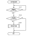
- the fall detection process shown in FIG. 12 will be described.
- the CPU 31 determines whether or not a detection signal from the mounting detection switch 42 is detected (step S101), and determines that a detection signal from the mounting detection switch 42 is detected (step S101: Yes). The process returns to step S101. If the CPU 31 determines that the detection signal from the mounting detection switch 42 is not detected (step S101: No), the process proceeds to step S102.
- step S102 the CPU 31 determines whether or not a detection signal from the grip detection switch 43 is detected. If the CPU 31 determines that the detection signal from the grip detection switch 43 is detected (step S102: Yes), the fall detection process is terminated. On the other hand, when the CPU 31 determines that the detection signal from the grip detection switch 43 is not detected (step S102: No), the process proceeds to step S103.
- step S103 the CPU 31 performs a winding execution process for winding the connection cable 3 by the winding means 20. Details of the winding execution processing will be described later. Then, when this process ends, the fall detection process ends.
- step S103 the winding execution process (step S103) executed in the above-described drop detection process will be described with reference to FIG.
- step S201 the CPU 31 sets a winding operation start timer.
- step S202 if the timer has not timed out (step S202: No), the CPU 31 suspends the process until time out.
- step S203 the CPU 31 rotates the winding restricting portion 28 upward, and the ratchet gear 27 and the tip pawl portion 28a of the winding restricting portion 28 Is disengaged.
- step S204 the CPU 31 sets the execution time of the winding operation in the timer.
- step S205 if the timer in which the execution time of the winding operation is set has not timed out (step S205: No), the CPU 31 suspends the processing until time out.
- step S206 the CPU 31 rotates the winding restricting portion 28 downward, and the ratchet gear 27 and the winding restricting portion.
- the leading end claw portion 28a of the 28 is engaged, and the rotation direction of the winding drum 26 is regulated.
- step S207 the CPU 31 operates the brake unit 23 between the rotating shaft 24 and the support shaft 24a to maintain the rotation of the winding drum 26 rotating integrally with the rotating shaft 24.
- the winding drum 26 is restricted from rotating in the rotation direction in which the connection cable 3 is wound, but can rotate in the direction in which the connection cable 3 is pulled out.
- the connection cable 3 may be pulled out by the weight of the image display unit 10 and the glasses-type frame 6 that supports the image display unit 10.
- the stop of the rotation of the winding drum 26 is maintained by the process in step S207, it is possible to prevent contact with the floor or the ground.
- the clip-shaped stand 8 or the hook 8 ′ serving as the holding means is provided in the storage case 2, and the extra length is connected when the image display unit 10 is held by the holding means. Since the configuration for winding the cable 3 around the storage case 2 can be realized with a relatively simple structure using a winding spring, the HMD 1 that is inexpensive and cost-effective can be provided.
- the monocular HMD 1 that projects an image to one eye of the user has been described as an example.
- the present invention is not limited thereto, and the binocular HMD 1 that projects an image to both eyes of the user can also be used.
- a winding means for the connection cable 3 can also be provided.
- the two image display units 10 and the control unit 30 provided for projecting images on both eyes are formed such that at least the part of the connection cable 3 to be wound is formed as one cable. It is desirable to be configured.
- the winding means 20 is provided on the upper portion of the control unit 30 and the connection cable 3 is wound.
- the present invention is not limited to this, and for example, a winding
- the take-up means 20 may be provided in the vicinity of the image display unit 10.
- the take-up means 20 may be provided at an intermediate position of the connection cable 3 that connects the image display unit 10 and the control unit 30.
- the holding means is provided on the upper surface or the front surface of the storage case 2, but the spectacle frame 6 that supports the image display unit 10 can be held, and the control unit 30 and the winding means 20 are provided.
- the installation position of the holding means is not particularly limited.
- connection cable 3 is wound up by the urging force of the winding spring 25 and the connection cable 3 is fed out by the motor M.
- the present invention is limited to this.
- a motor can be used for winding the connection cable 3.
- the clip-shaped stand 8 or the hook 8 ′ is provided as an example of the holding means, but the holding means is not limited to this, and the glasses-type frame 6 can be securely held. Any configuration can be used.
- An image display unit 10 that is mounted on the user's head and optically guides an image to the user's eyes, and is connected to the image display unit 10 via the connection cable 3 and controls to control image display.
- the clip-type stand 8 that is provided in the storage case 2 casing the control unit 30 and that holds the image display unit 10 is provided.
- connection cable 3 for connecting the image display unit 10 and the control unit 30 can be stored by the storage means, and the image display unit 10 can be stored by the clip-shaped stand 8. When holding, the connection cable 3 does not hang down and get in the way.
- connection cable 3 Since the winding means 20 for storing the connection cable 3 by winding at least a part of the connection cable 3 is provided as the storage means, for example, the connection cable 3 is prevented from being folded and stored. And disconnection of various signal lines in the connection cable 3 can be prevented.
- the winding switch 4 that causes the winding cable 20 to wind the connection cable 3 is provided, for example, the user can wind the connection cable 3 when necessary, and the user intends It is possible to prevent the connection cable from being wound up when not.
- the take-up switch 4 is provided in the image display unit 10, for example, the user performs the operation of winding the connection cable 3 with one hand while holding the image display unit 10 on the clip-shaped stand 8 that is a holding means. This is especially useful when you can't use one hand.
- the drawer switch 21 that allows the connection cable 3 taken up by the winding means 20 to be pulled out is provided in the storage case 2 in which the control unit 30 is casing, an image is displayed by, for example, the clip-shaped stand 8 that is a holding means. It is easy to operate the drawer switch 21 while the unit 10 is held. That is, when the pull-out switch 21 is in the image display unit 10, the image display unit 10 moves when the pull-out switch 21 is pressed if the clip-shaped stand 8 holds the image display unit 10 with play. The drawer switch 21 is difficult to press. However, by providing the drawer switch 21 in the storage case 2 in which the control unit 30 is casing, the drawer switch 21 can be operated without depending on the holding method of the image display unit 10.
- the frame detection means 5 is provided as detection means for detecting that the image display unit 10 is held by the clip-shaped stand 8 which is a holding means, and the winding means 20 includes the image display unit 10 by the clip-shaped stand 8.
- the connection cable 3 is taken up.
- the clip display stand 8 detects that the image display unit 10 is held, the connection cable 3 is wound. Since the take-up is executed, the user does not need to perform the take-up operation, and the user is released from the operation of taking up the connection cable 3, thereby improving convenience.
- the winding means 20 is connected to the wound connection cable 3 when it is detected by the frame detection means 5 as the detection means that the holding of the image display unit 10 by the clip-shaped stand 8 as the holding means is released.
- the connection cable 3 is sent out simply by removing the image display unit 10 from the clip-shaped stand 8, the user is released from the operation of sending out the connection cable 3, thereby improving convenience. be able to.
Landscapes
- Physics & Mathematics (AREA)
- General Physics & Mathematics (AREA)
- Optics & Photonics (AREA)
Abstract
画像表示ユニット10を保持する保持手段を備えたヘッドマウントディスプレイを提供する。利用者の頭部に装着され、利用者の眼に画像を光学的に導く画像表示ユニットと、画像表示ユニットと接続ケーブルを介して接続され、画像の表示を制御する制御ユニットと、を備えたヘッドマウントディスプレイにおいて、制御ユニットに設けられ、画像表示ユニットを保持する保持手段を備えたヘッドマウントディスプレイとした。
Description
本発明は、利用者の眼に画像を光学的に導く画像表示ユニットを備えたヘッドマウントディスプレイに関する。
従来、利用者の眼に画像を光学的に導く画像表示ユニットを利用者の頭部に取り付けるヘッドマウントディスプレイ(Head Mounted Display:HMD)が知られている(例えば、特許文献1参照。)。
かかるヘッドマウントディスプレイは、頭部に装着されるものであるため、利用者がいずれの方向を向いていても画像を認識させることができ、利用者の身体の動きを比較的制限することがない。特に、装置全体が小型化されたものであれば持ち運びが可能となり、今後広く普及していくものと予測される。
しかしながら、持ち運び可能に構成されたヘッドマウントディスプレイでは、利用者は、画像表示ユニットを取り外したときに、この画像表示ユニットの置き場所が無くて困る場合がある。例えば、移動途中のバスや電車内で画像表示ユニットを頭部に装着し、歩行中は画像表示ユニットを頭部から外すような場面では、利用者は、歩行中は画像表示ユニットを手で保持しておかなければならない。
そのため、折角、持ち運び可能に構成されたにも関わらず、利用者は、ヘッドマウントディスプレイの利用を躊躇してしまう恐れがある。ヘッドマウントディスプレイは、娯楽の分野のみならず、医療、又は工場等の現場でも活用が始まっており、このような課題は、普及の足かせになってしまう恐れがある。
本発明は、上述したような課題に鑑みてなされたものであり、利用者の頭部から取り外した画像表示ユニットを保持しておくことができるヘッドマウントディスプレイを提供することを目的とする。
上記目的を達成するために、請求項1に係る発明は、利用者の頭部に装着され、前記利用者の眼に画像を光学的に導く画像表示ユニットと、前記画像表示ユニットと接続ケーブルを介して接続され、前記画像の表示を制御する制御ユニットと、を備えたヘッドマウントディスプレイにおいて、前記制御ユニットに設けられ、前記画像表示ユニットを保持する保持手段を備えたことを特徴とするヘッドマウントディスプレイとした。
また、請求項2に係る発明は、請求項1に記載のヘッドマウントディスプレイにおいて、前記接続ケーブルを収納する収納手段を備えたことを特徴とする。
また、請求項3に係る発明は、請求項2に記載のヘッドマウントディスプレイにおいて、前記収納手段は、前記接続ケーブルの少なくとも一部を巻き取ることにより前記接続ケーブルを収納する巻取手段を備えたであることを特徴とする。
また、請求項4に係る発明は、請求項3に記載のヘッドマウントディスプレイにおいて、前記巻取手段により前記接続ケーブルの巻き取りを実行させる操作スイッチを備えることを特徴とする。
また、請求項5に係る発明は、請求項4に記載のヘッドマウントディスプレイにおいて、前記操作スイッチを画像表示ユニットに設けたことを特徴とする。
また、請求項6に係る発明は、請求項3に記載のヘッドマウントディスプレイにおいて、前記巻取手段により巻き取られた接続ケーブルの引き出しを許可するスイッチを前記制御ユニットに設けたことを特徴とする。
また、請求項7に係る発明は、請求項3に記載のヘッドマウントディスプレイにおいて、前記画像表示ユニットが前記保持手段により保持されたことを検出する検出手段を備え、前記巻取手段は、前記保持手段による前記画像表示ユニットの保持が前記検出手段により検出されたとき、前記接続ケーブルの巻き取りを実行することを特徴とする。
また、請求項8に係る発明は、請求項7に記載のヘッドマウントディスプレイにおいて、前記巻取手段は、前記保持手段による前記画像表示ユニットの保持が解除されたことが前記検出手段により検出されたとき、前記巻き取られた接続ケーブルを送り出すことを特徴とする。
本発明のヘッドマウントディスプレイによれば、画像表示ユニットとは別に制御ユニットを設け、この制御ユニットに画像表示ユニットを保持する保持手段を設けている。従って、利用者は制御ユニットを腰などに取り付けておくことにより、頭部から取り外した画像表示ユニットを保持手段で保持させることができ、画像表示ユニットの置き場所に困ることがない。
以下、本実施形態に係るヘッドマウントディスプレイ(以下、「HMD」と呼ぶ。)の一例について、図面を参照して説明する。なお、本実施形態では、HMDは、画像情報に基づいて生成された画像光を2次元走査して利用者の眼に投射し、画像光を網膜上で走査する網膜走査型として説明するが、本発明はこれに限定されるものではなく、LCD型のHMDであってもよい。
[1.HMD1の概要]
[HMD1の構成]
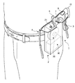
まず、HMD1の全体的な構成について、図1を参照しながら説明する。
[HMD1の構成]
まず、HMD1の全体的な構成について、図1を参照しながら説明する。
本実施形態に係るHMD1は、図1に示すように、利用者の頭部に装着され、利用者の眼に画像を光学的に導く画像表示ユニット10と、画像表示ユニット10と接続ケーブル3を介して接続され、画像の表示を制御する制御ユニット30とを備えている。接続ケーブル3は、後述する光ファイバケーブル50(図2参照)、及び、後述する同期信号(図2参照)などを伝達するための伝送線を被覆して形成したものである。
制御ユニット30は、画像信号を形成し、この画像信号に応じた強度の光束を画像光として接続ケーブル3内の光ファイバケーブル50へ出射する。
画像表示ユニット10は、制御ユニット30から接続ケーブル3内の光ファイバケーブル50を介して出射される光束を走査して利用者の眼に投射し、画像信号に応じた強度の光束を利用者の眼の網膜上で画像光として2次元方向に走査する。この画像表示ユニット10は、略L字状の形状をしており、眼鏡型フレーム6の利用者からみて左のテンプル6bとフロント6aとの接続角部分、すなわち、蝶番6cの近傍に支持部6fを介して配設されている。しかも、画像表示ユニット10にはハーフミラー9がステーを介して利用者の左眼前方に突設されており、画像表示ユニット10から出射される画像光がハーフミラー9で反射して利用者の眼に入射される。
ハーフミラー9は半透明であるため、画像表示ユニット10から出射される画像光を反射して利用者の眼に入射するだけではなく、外光もハーフミラー9を透過して利用者の眼に入射する。従って、利用者は外光による外景に画像光による画像を重ねて視認することができる。このようにHMD1は、外光を透過しつつ、画像光を利用者の眼に投射するシースルー型のHMDである。
[2.HMD1の電気的構成及び光学的構成]
次に、図2を参照しながら、HMD1の電気的構成及び光学的構成について説明する。HMD1の構造的特徴としては、上述したように、制御ユニット30、ハーフミラー9を具備する画像表示ユニット10、眼鏡型フレーム6、及び接続ケーブル3を備えたところにある。
次に、図2を参照しながら、HMD1の電気的構成及び光学的構成について説明する。HMD1の構造的特徴としては、上述したように、制御ユニット30、ハーフミラー9を具備する画像表示ユニット10、眼鏡型フレーム6、及び接続ケーブル3を備えたところにある。
まず、制御ユニット30に関する電気的及び光学的構成について説明する。制御ユニット30は、図2に示すように、HMD1全体の動作を統括制御するものである。そして、HMD1全体の動作の制御をするためのCPU31、HMD1全体の動作の制御をするための各種プログラム等が記憶されたワークメモリ32が設けられている。
ワークメモリ32は、例えば、各種プログラム等が記憶された不揮発性のフラッシュメモリ、及び各種プログラムを実行するための一時記憶領域として使用されるRAMなどで構成される。そして、CPU31はワークメモリ32に記憶された各種プログラムを読み出して実行することで、利用者の眼に画像を光学的に導く画像表示処理、画像表示ユニット10の落下検出処理、及び巻取手段20による接続ケーブル3の巻き取り処理などを実行する。
制御ユニット30には、画像処理回路35、光源制御回路36、R光源36a、G光源36b、B光源36c、及び合波部37が設けられている。
画像処理回路35は、画像信号入力手段34から供給される画像信号Sから画像情報を画素単位で読み出し、読み出した画素単位の画像情報に基づいてR(赤色),G(緑色),B(青色)の各色用の画像信号を生成する。
光源制御回路36は、画像処理回路35から画素単位で出力されるR画像信号、G画像信号、B画像信号の各画像信号に基づき、R(赤色),G(緑色),B(青色)の各色用の駆動電流を生成し、R光源36a,G光源36b,B光源36cに供給する。
R光源36a,G光源36b,B光源36cは、例えば、半導体レーザ又は高調波発生機構付き固体レーザとして構成することが可能である。なお、半導体レーザを用いる場合は駆動電流を直接変調して、光束(レーザ光)の強度変調を行うことができるが、固体レーザを用いる場合は、各レーザそれぞれに外部変調器を備えて光束の強度変調を行う必要がある。
合波部37は、R光源36a,G光源36b,B光源36cから出射された各色の光束を同一光路に合流して合波し、画像光を形成して光ファイバケーブル50の一端部へ入射する。
光ファイバケーブル50の他端部は画像表示ユニット10に接続されている。この画像表示ユニット10は、光ファイバケーブル50から入射する画像光を走査して、利用者の眼に入射させ、利用者の眼の網膜上で画像光を2次元方向に走査する。
画像表示ユニット10には、走査部11、走査モジュール駆動回路12、及びハーフミラー9が設けられている。
走査部11は、光ファイバケーブル50を介して入射した画像光をコリメートして平行光化し、このように平行光化した画像光を主走査方向とこの主走査方向に略直交する副走査方向とに2次元的に走査する。走査部11による画像光の走査は、走査モジュール駆動回路12により制御される。走査モジュール駆動回路12は、走査部11による画像光の走査位置が、画像処理回路35から出力される同期信号に基づいた走査位置になるように、走査部11を制御する。
接眼光学系40は、接眼レンズとハーフミラー9などから構成されている。この接眼光学系40は、接眼レンズにより形成される射出瞳の位置がハーフミラー9の調整により利用者の瞳孔位置に合うように配置されており、これにより、走査部11で走査された画像光は、利用者の瞳孔に入射し、利用者の眼の網膜上で2次元方向に走査される。
[3.画像表示ユニットの保持手段と接続ケーブルの収納手段の構成]
上記のように構成されたHMD1は、収納手段としての接続ケーブル3の少なくとも一部を巻き取る巻取手段と、画像表示ユニット10を保持する保持手段とを有している。これにより、HMD1を持ち運ぶときに利便性を向上させている。以下、保持手段及び巻取手段の構成について具体的に説明する。
上記のように構成されたHMD1は、収納手段としての接続ケーブル3の少なくとも一部を巻き取る巻取手段と、画像表示ユニット10を保持する保持手段とを有している。これにより、HMD1を持ち運ぶときに利便性を向上させている。以下、保持手段及び巻取手段の構成について具体的に説明する。
[3.1.画像表示ユニットの保持手段の構成]
以下、本実施形態における保持手段の構成について、図3~図5を用いて説明する。
以下、本実施形態における保持手段の構成について、図3~図5を用いて説明する。
図3に示すように、本実施形態における保持手段は、制御ユニット30をケーシングした収納ケース2の上面に立設されたクリップ状スタンド8としている。利用者は、収納ケース2を腰に装着し、頭部から外した画像表示ユニット10をこのクリップ状スタンド8に保持させておくことにより、歩行中であっても画像表示ユニットを手で保持しておく必要がない。かかる画像表示ユニット10の保持は、画像表示ユニット10を支持する眼鏡型フレーム6をクリップ状スタンド8により保持させることにより行われる。
なお、利用者がHMD1をしばらくの間使用しないときにも、収納ケース2に設けられたクリップ状スタンド8に眼鏡型フレーム6を保持させることで、HMD1をコンパクトにまとめておくことができる。そのため、保管場所を取らず邪魔にならない。
また、クリップ状スタンド8に眼鏡型フレーム6が保持されている状態では、接続ケーブル3は、図3に示すように、眼鏡型フレーム6の保持には不要な長さの分だけ、後述の巻取手段20により収納ケース2の内部に巻き取られる。従って、HMD1の未使用時には接続ケーブル3が邪魔にならず、安全に仮置きすることができる。
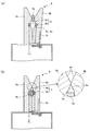
以下、保持手段であるクリップ状スタンド8の構成及び動作について図4及び図5を用いてさらに詳細に説明する。図4及び図5は、図1のクリップ状スタンド8のA-A線における断面図である。
図4に示すように、クリップ状スタンド8は、左右のクリップ片8a,8bを対峙した構成で制御ユニット30の収納ケース2上側面に立設されている。一方のクリップ片8aの基端は収納ケース2上に固定される。また、他方のクリップ片8bの基端部は、他端を収納ケース2に固設した巻きバネ8cの一端に連設される。このようにクリップ状スタンド8を構成することで、巻きバネ8cの付勢力によって左右のクリップ片8a,8b間に画像表示ユニット10の眼鏡型フレーム6を挟持することができる。
しかも、図5(b)に示すように、左右のクリップ片8a,8bの上端は、それぞれ下方狭窄状のテーパー8d,8dが形成されている。そのため、テーパー8d,8d間に眼鏡型フレーム6のフロント6a中央部を挿入してそのままクリップ片8bの巻きバネ8cの付勢に抗して下方に押込むことができる。このように押し込まれたフロント6a中央部は左右のクリップ片8a,8bによって挟持される。これにより画像表示ユニット10を支持している眼鏡型フレーム6の保持が行われる。
さらに、テーパー8d,8dの下方であり、かつ左右のクリップ片8a,8bの中央には凹部5c,5cが対峙して形成されており、これらの凹部5c,5cにフロント6aを検出するためのフレーム検出手段5が配設されている。このフレーム検出手段5は、図5(a)に示すように、例えば、発光部5aと、受光部5bとからなるフォトセンサが用いられる。図5(b)に示すように、フロント6aがテーパー8d,8d間に挿入して押し込まれて、凹部5cにフロント6aが到達すると、発光部5aと受光部5bとの間にフロント6aが位置することになり、発光部5aから出射した光が受光部5bで受光できなくなる。フレーム検出手段5では、このように発光部5aから出射した光が受光部5bで受光できなくなったときに、画像表示ユニット10がクリップ状スタンド8により保持されたことを示す信号(以下、「保持信号」という)を制御ユニット30に出力する。
また、左右のクリップ片8a,8bの中央に形成された凹部5c,5cの上部は、上方狭窄状のテーパー8e,8eが形成されており、左右のクリップ片8a,8b間に保持されたフロント6aを利用者が上方に持ち上げると、クリップ片8bは巻きバネの付勢に抗して拡開する。これにより、クリップ状スタンド8による眼鏡型フレーム6の保持状態を解除することができる。
このように、HMD1では、利用者が任意に、眼鏡型フレーム6に支持された画像表示ユニット10を収納ケース2の上側面に設けられた保持手段であるクリップ状スタンド8に着脱自在としている。
[3.2.収納手段の構成]
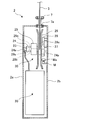
本実施形態における収納手段としての巻取手段20の構成について、図6及び図7を用いて説明する。なお、以下の説明では巻取手段20を収納手段の一例として説明するが、接続ケーブル3の収納方法は巻き取りに限定されるものではなく、接続ケーブル3を収納する構成であればよい。例えば、接続ケーブル3を折り返して収納ケース2内に収納したり、接続ケーブル3を収納ケース2内の任意の位置に押し込むように収納したりする構成であってもよい。
本実施形態における収納手段としての巻取手段20の構成について、図6及び図7を用いて説明する。なお、以下の説明では巻取手段20を収納手段の一例として説明するが、接続ケーブル3の収納方法は巻き取りに限定されるものではなく、接続ケーブル3を収納する構成であればよい。例えば、接続ケーブル3を折り返して収納ケース2内に収納したり、接続ケーブル3を収納ケース2内の任意の位置に押し込むように収納したりする構成であってもよい。
本実施形態における巻取手段20は、図6及び図7に示すように、制御ユニット30をケーシングした収納ケース2の上半分に収納されている。
収納ケース2の前壁2aと後壁2bとの間に架設された支持軸24aの外周に回転軸24が回転自在に遊嵌されている。そして、収納ケース2の前壁2aから順に、回転軸24の外周面に巻きバネ25、巻取ドラム26、及びラチェット歯車27が一体に連結され、回転軸24の回転と同調するように配設されている。
また、ラチェット歯車27の上部には、収納ケース2の後壁2bに軸支された巻取規制部28としての先端爪部28aがラチェット歯車27に係合可能に設置されている。
回転軸24と支持軸24aとの間には、ブレーキユニット23が設けられている。このブレーキユニット23は、制御ユニット30からの作動指示により、回転軸24の回転を停止可能なように構成されている。
回転軸24と支持軸24aとの間に設けられたブレーキユニット23には、支持軸24aに出没自在の摩擦係数の高いゴムが埋設されている。制御ユニット30からの電気的な信号による作動指示により、ブレーキユニット23は、支持軸24aから回転軸24の内周面にゴムを突出させ、ゴムと回転軸24との摩擦によって回転軸24の回転を停止させる。
このブレーキユニット23は、後述する巻取手段20による接続ケーブル3の巻き取りが実行された後に、その状態を維持するために設けられている。
巻きバネ25の一端は回転軸24に連結されると共に、その他端は収納ケース2に固定されている。そして、回転軸24の回転にともない巻きバネ25の巻取り、又はその解除がなされるように構成されている。そして、接続ケーブル3を収納ケース2の外部に引き出すと回転軸24の回転にともない巻きバネ25は巻取られて付勢力を蓄積し接続ケーブル3を収納方向に付勢することになる。そのため、巻きバネ25を解除すると巻きバネ25の付勢力により回転軸24及び巻取ドラム26が回転し、接続ケーブル3がこの巻取ドラム26に巻き付けられる。
また、ラチェット歯車27とその上部に設けられた巻取規制部28とによりラチェット機構が構成されている。このラチェット機構は、ラチェット歯車27と巻取規制部28の先端爪部28aとを係合させて、巻取ドラム26の回転方向を一定の方向に制限する。これにより、接続ケーブル3を収納ケース2の外部に引き出す方向には巻取ドラム26の回転を可能とする一方、収納ケース2の内部に接続ケーブル3を巻き取る方向には巻取ドラム26の回転を不可とすることができる。
すなわち、本実施形態における巻取手段20は、巻きバネ25の付勢力による接続ケーブル3の巻き取り動作を禁止するために、ラチェット歯車27と巻取規制部28の先端爪部28aとを係合させて巻取ドラム26の回転方向を規制している。
巻取規制部28の通常の位置では、ラチェット歯車27と巻取規制部28の先端爪部28aとが係合位置にある。そして、制御ユニット30から巻取規制部28に連設されている回転ソレノイド22に駆動信号が送信されると、先端爪部28aは上方に回動して、その結果ラチェット歯車27と先端爪部28aとの係合が解除され、巻取ドラム26の回転方向の規制は解除される。また、回転ソレノイド22への駆動信号の送信を停止すると、先端爪部28aは通常の位置に復帰してラチェット歯車27と係合されて、巻取ドラム26の回転方向が規制される。
このように、接続ケーブル3を収納ケース2の外部に引き出す方向には巻取ドラム26を回転可能としており、接続ケーブル3を収納ケース2の外部に引き出すと回転軸24の回転にともない巻きバネ25は巻取られて付勢力を蓄積し接続ケーブル3を収納方向に付勢する。そして、接続ケーブル3を巻き取るときには、巻取規制部28を上方に回動させてラチェット歯車27と巻取規制部28の先端爪部28aとの係合を解除することにより、巻きバネ25の付勢力により、巻取ドラム26は収納ケース2の内部に接続ケーブル3を巻き取る方向に回転し、接続ケーブル3の巻き取り動作が実行される。
巻取手段20による接続ケーブル3の巻き取り動作が終了すると、制御ユニット30は、巻取規制部28を下方に可動させてラチェット歯車27と巻取規制部28の先端爪部28aとを再度係合させて、巻取ドラム26の回転を規制するとともに、回転軸24と支持軸24aとの間のブレーキユニット23を作動させて、回転軸24と一体に回転する巻取ドラム26の回転を停止させた状態を維持する。
本実施形態における巻取手段20には、図7に示すようにラチェット歯車27の下部に巻取ドラム26を回転させるためのモータMが設けられている。モータMはその先端の回転部Maを収納ケース2の後壁2b側の巻取ドラム26の背面に当接させている。回転部Maは、例えば、その周面を摩擦係数の高い対磨耗性に優れた樹脂により形成した部材から構成されており、回転部Maを回転させることで回転部Maの先端と巻取ドラム26との間で生じる摩擦により、当接した巻取ドラム26を回転させる。
モータMによる巻取ドラム26の回転方向は、巻取ドラム26に巻き取られた接続ケーブル3を収納ケース2の外部に送り出す回転方向である。また、この巻取ドラム26の回転方向には、上述したように巻きバネ25による付勢力が働いているため、モータMの回転トルクは少なくとも巻きバネ25による付勢力を上回る回転トルクとしている。
なお、接続ケーブル3は、巻取手段20内では、図7に示すように配設されている。すなわち、接続ケーブル3は、制御ユニット30の上面からその上部に配設された支持軸24aの中心を経由して、支持軸24a内の第1端子部29aに接続されている。そして、接続ケーブル3は、第2端子部29bからさらに巻取ドラム26の中心を経由して、その上方の入出口7aから収納ケース2の外部へと繋がる。
第1端子部29aは、支持軸24a内で固定されている一方、第2端子部29bは回転軸24内で固定されており、第1端子部29aに対して第2端子部29bが回転可能に、コネクタカバー29c介して接続されている。このコネクタカバー29cは、第1端子部29aに対して第2端子部29bが回動した場合でも、接続ケーブル3内で伝送される画像光及び各種信号を制御ユニット30と画像表示ユニット10との間で伝送することができるように、第1端子部29aと第2端子部29bとを接続する。なお、画像表示ユニット10の光ファイバケーブル50は、制御ユニット30の光ファイバケーブル50と回転軸24の軸中心で回転可能に接続される。また、第1端子部29aでは、各信号を伝達する端子が円環状溝で形成され、これらの円環状溝が同心円状に配置されている。一方、第2端子部29bでは、各信号を伝達する端子が凸部に形成されて、各凸部が円環状溝に嵌合している。
[4.接続ケーブルの巻き取り及び引き出し動作]
本実施形態においては、上述したように、利用者がHMD1の使用を中止又は中断するとき、或は、頭部から外した画像表示ユニット10を保持手段であるクリップ状スタンド8に保持させるときに、制御ユニット30と画像表示ユニット10とを接続する接続ケーブル3を、眼鏡型フレーム6の保持には必要としない長さの分だけ巻き取ることができるようにしている。
本実施形態においては、上述したように、利用者がHMD1の使用を中止又は中断するとき、或は、頭部から外した画像表示ユニット10を保持手段であるクリップ状スタンド8に保持させるときに、制御ユニット30と画像表示ユニット10とを接続する接続ケーブル3を、眼鏡型フレーム6の保持には必要としない長さの分だけ巻き取ることができるようにしている。
接続ケーブル3の巻取りは、制御ユニット30により制御される。すなわち、画像表示ユニット10の上面に設けられた巻取スイッチ4(図1参照)が押下されたことを検出したとき、又は、眼鏡型フレーム6のクリップ状スタンド8への保持の検出がフレーム検出手段5によって行われたとき、制御ユニット30は接続ケーブル3の巻取りを実行する。
接続ケーブル3の巻取りを行うために制御ユニット30は、巻取手段20の巻取規制部28を上方に回動させてラチェット歯車27と巻取規制部28の先端爪部28aとの係合を解除する。これにより、巻きバネ25の付勢力により、巻取ドラム26は収納ケース2の内部に接続ケーブル3を巻き取る方向に回転することができ、接続ケーブル3は眼鏡型フレーム6の保持には必要にない長さの分だけ巻き取られる。
一方、接続ケーブル3の引き出しは、引出スイッチ21の押下、又は、クリップ状スタンド8からの眼鏡型フレーム6の取り外しによって行うことができる。これにより、利用者は、巻き取った接続ケーブル3を引き出して、眼鏡型フレーム6を頭部に装着できる。
すなわち、利用者が、収納ケース2の上面に設けられた引出スイッチ21を押下すると、ブレーキユニット23による回転軸24の回転停止が制御ユニット30により解除されて、巻取ドラム26は収納ケース2の外部に接続ケーブル3が引き出される方向には回転可能となる。従って、利用者が引出スイッチ21を押下している間は、利用者が接続ケーブル3を収納ケース2の外部に手動で引き出すことができる。
また、クリップ状スタンド8からの眼鏡型フレーム6の取り外しの検出がフレーム検出手段5によって行われたとき、次のように、制御ユニット30は接続ケーブル3の引き出しを実行する。すなわち、制御ユニット30は、まず、ブレーキユニット23による回転軸24の回転停止を解除する。そして、制御ユニット30は、モータMを駆動させて、巻取ドラム26に巻き取られた接続ケーブル3を収納ケース2の外部に送り出す。
なお、収納ケース2の上面の接続ケーブル3の入出口7aにはケーブルガイド7が設けられている。このケーブルガイド7は、例えば、耐熱、耐磨耗性に優れたチタン(Ti)などの金属材料で形成され、収納ケース2の内部への接続ケーブル3の巻き取り及び収納ケース2の外部への接続ケーブル3の引き出しを円滑にするためのものである。
[4.1.接続ケーブルの巻き取り及び引き出し処理]
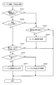
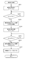
以下、上述した構成のHMD1において実行される接続ケーブルの巻き取り及び引き出し処理を、図10を用いて説明する。この巻き取り及び引き出し処理は、制御ユニット30のCPU31が、上述した制御ユニット30のワークメモリ32に記憶されているプログラムを読み出して実行する。
以下、上述した構成のHMD1において実行される接続ケーブルの巻き取り及び引き出し処理を、図10を用いて説明する。この巻き取り及び引き出し処理は、制御ユニット30のCPU31が、上述した制御ユニット30のワークメモリ32に記憶されているプログラムを読み出して実行する。
まず、制御ユニット30のCPU31は、フレーム検出手段5からの出力信号に基づいて、収納ケース2に設けられているクリップ状スタンド8に、眼鏡型フレーム6が保持されているか否かを判定する(ステップS301)。この処理において、フレーム検出手段5から保持信号が出力されたときに、眼鏡型フレーム6が保持されていると判定する。そして、CPU31は、眼鏡型フレーム6が保持されていると判定する(ステップS301:Yes)と、ステップS303へ処理を移す。一方、CPU31は、眼鏡型フレーム6が保持されていないと判定する(ステップS301:No)と、ステップS302に処理を移す。
ステップS302において、CPU31は、画像表示ユニット10に設けられた巻取スイッチ4が押下されたか否かを判定する。この処理において、CPU31は、巻取スイッチ4が押下された判定する(ステップS302:Yes)と、ステップS303へ処理を移す。一方、CPU31は、巻取スイッチ4が押下されていないと判定する(ステップS302:No)と、ステップS305へ処理を移す。
ステップS303において、CPU31は、既に巻取手段20による接続ケーブル3の巻き取りが実行された巻取り実行済み状態か否かを判定する。この処理において、CPU31は、巻取り実行済み状態と判定する(ステップS303:Yes)と、本巻き取り及び引き出し処理を終了する。一方、CPU31は、巻取り実行済み状態ではないと判定する(ステップS303:No)と、ステップS304へ処理を移す。
ステップS304において、CPU31は、ケーブル巻き取り処理を実行する。この処理において、CPU31は、巻取手段20の巻取規制部28に設けられた回転ソレノイド22に対して駆動信号を出力して回転ソレノイド22を駆動させることにより、巻取規制部28を上方に回動させてラチェット歯車27と巻取規制部28の先端爪部28aとの係合を解除する。これにより、巻きバネ25の付勢力により、巻取ドラム26は収納ケース2の内部に接続ケーブル3を巻き取る方向に回転することができ、接続ケーブル3は眼鏡型フレーム6の保持に必要のない長さの分だけ巻き取られる。なお、このケーブル巻き取り処理において、所定長さの接続ケーブル3を巻取手段20の巻取ドラム26に巻き取り終えると、CPU31は、巻取手段20の支持軸24aと回転軸24との間に設けられたブレーキユニット23により、回転軸24を回転不可としてこの状態を維持する。この処理が終了すると本巻き取り及び引き出し処理を終了する。
ステップS305において、CPU31は、既に十分な長さの接続ケーブル3が巻取手段20の巻取ドラム26から引き出されているか否かを判定する。この処理において、引き出されていると判定する(ステップS305:Yes)と、CPU31は、本巻き取り及び引き出し処理を終了する。一方、引き出されていないと判定する(ステップS305:No)と、CPU31は、処理をステップS306へ処理を移す。
上記ステップS305の処理により、画像表示ユニット10を支持した眼鏡型フレーム6を、利用者の頭部に装着するのに必要十分な長さの接続ケーブル3が、既に巻取手段20の巻取ドラム26から引き出されている場合は、それ以上の接続ケーブル3の引き出しを抑制することができる。
ステップS306において、CPU31は、引出スイッチ21の入力を検出しているか否かを判定する。この処理において、引出スイッチ21の入力を検出していると判定する(ステップS306:Yes)と、CPU31は、ステップS308へ処理を移す。一方、引出スイッチ21の入力を検出していないと判定する(ステップS306:No)と、CPU31は、ステップS307へ処理を移す。
ステップS307において、CPU31は、接続ケーブル3の自動送り出し処理を実行する。この処理では、CPU31は、巻取手段20のモータMに対して駆動信号を供給する。これにより巻取ドラム26は、巻取ドラム26に巻き取られた接続ケーブル3を収納ケース2の外部に送り出す方向に回転して、画像表示ユニット10を支持した眼鏡型フレーム6を利用者の頭部に装着するのに必要十分な長さの接続ケーブル3が自動的に送り出される。そしてこの処理が終了すると本巻き取り及び引き出し処理を終了する。
また、ステップS308において、CPU31は、接続ケーブル3の引き出しを許可する。この処理では、CPU31は、利用者による引出スイッチ21の押下を検出すると、ブレーキユニット23による回転軸24の回転停止を解除することで、巻取ドラム26は収納ケース2の外部に接続ケーブル3が引き出される方向には回転可能となり、利用者が接続ケーブル3を収納ケース2の外部に引き出すことができる。そしてこの処理が終了すると本巻き取り及び引き出し処理を終了する。
上述してきたように、本実施形態に係るHMD1では、利用者がHMD1の使用を中止又は中断するとき、或は、頭部から画像表示ユニット10を外したときに、巻取スイッチ4を押下するか、又は、眼鏡型フレーム6をクリップ状スタンド8に保持させることで、接続ケーブル3を眼鏡型フレーム6の保持には必要のない長さの分だけ巻取手段20により巻き取ることができる。
一方、利用者がHMD1の使用を再開するときは、引出スイッチ21を押下するか、又は、クリップ状スタンド8に保持された眼鏡型フレーム6を取り外すことにより、接続ケーブル3を巻取手段20から引き出すことができる
[5.保持手段の変形例]
ここで、上述した保持手段の変形例を、図8及び図9を参照して説明する。図8及び図9は保持手段の変形例の構成を示す図である。なお、以下の変形例においては、上述した実施形態の構成と異なる箇所以外は、理解を容易とするため同じ符号を付して説明を省略する。
ここで、上述した保持手段の変形例を、図8及び図9を参照して説明する。図8及び図9は保持手段の変形例の構成を示す図である。なお、以下の変形例においては、上述した実施形態の構成と異なる箇所以外は、理解を容易とするため同じ符号を付して説明を省略する。
図8に示すように、変形例における保持手段は、巻取手段20及び制御ユニット30をケーシングした収納ケース2の前面にフック8’として取り付けられている。
フック8’は、図9に示すように、所定の弾性を有する一枚の板バネをアーム状に形成して構成されている。アーム状のフック8’は、眼鏡型フレーム6のフロント6aを保持する空間を有し、その先端に折り返し形状の係合部8a’を備えている。そして、眼鏡型フレーム6のフロント6aは、先端の係合部8a‘から、フロント6aを保持する空間に対して着脱自在とされている。
収納ケース2の前面に取り付けられたフック8’の基端部には、フレーム検出手段5’として、例えば、重量センサが設けられている。このフレーム検出手段5’はフック8’に眼鏡型フレーム6が保持された場合の重量の変化により、眼鏡型フレーム6がフック8’へ保持されたことを検出する。
なお、フレーム検出手段5’として重量センサではなく、例えば、収納ケース2の前面にフレーム検出手段5’としての図示しないスイッチを設け、フック8’が眼鏡型フレーム6を保持したときの重みでたわんで当該スイッチを押圧するように構成し、スイッチが押圧されたことを検出することにより、眼鏡型フレーム6がフック8’へ保持されたことを検出してもよい。
このように、変形例においては、収納ケース2の前面に保持手段を設けたため、利用者にとって、フック8’への眼鏡型フレーム6の着脱が容易となり、なおかつ、眼鏡型フレーム6を保持した状態でも、収納ケース2の上面に設けられた引出スイッチ21の操作がし易い。
さらに、図9に示すように、変形例においては、収納ケース2の前面にフック8’を設けるとともに、収納ケース2の後面には、例えば、ベルト装着部60が設けられている。このベルト装着部60に利用者のベルトを通すことにより、巻取手段20及び制御ユニット30をケーシングした収納ケース2を利用者の腰に装着できるようにしている。
[6.落下検出手段を加えた変形例]
利用者が頭部に画像表示ユニット10を装着して使用中に、当該画像表示ユニット10が利用者の頭部から落下したことを検出する落下検出手段を付加し、この落下検出手段により画像表示ユニット10の落下を検出したとき、上述した接続ケーブル3を収納ケース2に巻き取る巻取手段20を作動させて、接続ケーブル3の少なくとも一部を巻き取る機能を付加した変形例について説明する。これにより、利用者が誤って画像表示ユニット10を落下したときでも、画像表示ユニット10が床や地面などへ激突することを防止することができる。
利用者が頭部に画像表示ユニット10を装着して使用中に、当該画像表示ユニット10が利用者の頭部から落下したことを検出する落下検出手段を付加し、この落下検出手段により画像表示ユニット10の落下を検出したとき、上述した接続ケーブル3を収納ケース2に巻き取る巻取手段20を作動させて、接続ケーブル3の少なくとも一部を巻き取る機能を付加した変形例について説明する。これにより、利用者が誤って画像表示ユニット10を落下したときでも、画像表示ユニット10が床や地面などへ激突することを防止することができる。
[6.1.落下検出手段の構成]
落下検出手段は、画像表示ユニット10の加速度を検出する加速度センサ41、眼鏡型フレーム6が利用者に装着されていることを検出する装着検出スイッチ42、及び眼鏡型フレーム6を利用者が手で把持していること検出する把持検出スイッチ43などからなる。
落下検出手段は、画像表示ユニット10の加速度を検出する加速度センサ41、眼鏡型フレーム6が利用者に装着されていることを検出する装着検出スイッチ42、及び眼鏡型フレーム6を利用者が手で把持していること検出する把持検出スイッチ43などからなる。
以下、図1を用いて、画像表示ユニット10が落下したことを検知するための各種スイッチ及びセンサ、当該画像表示ユニット10及び眼鏡型フレーム6が利用者に把持されてことを検出するスイッチの構成を説明する。
図1に示すように、眼鏡型フレーム6を利用者が手で把持していることを検出する把持検出スイッチ43は、眼鏡型フレーム6のフロント6aと左右のテンプル6bを接続する蝶番6cの近傍に2つ設けられている。そして、当該眼鏡型フレーム6に設けられた把持検出スイッチ43が利用者により押下されていることを検出すると検出信号を本体ユニット30に供給する。
また、加速度センサ41は、画像表示ユニット10の内部に設けられている。この加速度センサ41は、画像表示ユニット10が所定値以上の加速度で変位したことを検出すると、検出信号を制御ユニット30に供給する。
図示しない装着検出スイッチ42は、眼鏡型フレーム6の左右のテンプル6bの、利用者の側頭部から耳にかけて接触する面と、眼鏡型フレーム6のフロント6aに設けられたパッド6dの利用者の鼻と接触する面とに複数個設けられている。
この装着検出スイッチ42は、眼鏡型フレーム6が利用者の頭部(つまり、顔面)に装着されていることを検出すると、検出信号を制御ユニット30に供給する。
また、装着検出スイッチ42、加速度センサ41及び把持検出スイッチ43の検出信号は、画像表示ユニット10から接続ケーブル3を介して制御ユニット30に供給される。
[6.2.画像表示ユニットの各種落下形態における巻取手段の動作]
変形例における画像表示ユニット10の各種の落下形態における巻取手段20の動作を、図11を用いて具体的に説明する。
変形例における画像表示ユニット10の各種の落下形態における巻取手段20の動作を、図11を用いて具体的に説明する。
初めに、図11(a)に示すように、本実施形態に係るHMD1を、利用者が立位状態で使用した場合は、画像表示ユニット10は眼鏡型フレーム6に支持されて利用者の頭部に装着されている。そして、利用者の腰のベルト位置に、収納ケース2が所定のケースカバーなどにより保持されている。
次に、図11(b)に示すように、制御ユニット30は、画像表示ユニット10及び眼鏡型フレーム6が利用者の頭部から外れて落下したことを検出すると、巻取手段20が動作して、所定長さの接続ケーブル3を収納ケース2の内部に巻き取るように作動する。
最後に、図11(c)に示すように、画像表示ユニット10及び眼鏡型フレーム6の落下が、床面から所定の距離d1に達すると、制御ユニット30は、巻取手段20による接続ケーブル3の巻取り動作を停止する。
また、利用者が椅子に座った状態で使用した場合は、図11(d)に示すように、画像表示ユニット10及び眼鏡型フレーム6の落下が、床面から所定の距離d2に達すると、制御ユニット30は、巻取手段20による接続ケーブル3の巻取り動作を停止する。
[6.3.落下検出手段の落下検出処理と巻取手段の巻取実行処理]
利用者が頭部に装着した画像表示ユニット10の落下を検出する落下検出処理について説明する。なお、この落下検出処理は、利用者が頭部に画像表示ユニット10を装着した状態からの処理である。
利用者が頭部に装着した画像表示ユニット10の落下を検出する落下検出処理について説明する。なお、この落下検出処理は、利用者が頭部に画像表示ユニット10を装着した状態からの処理である。
図12に示す落下検出処理を説明する。CPU31は、装着検出スイッチ42からの検出信号を検出しているか否かを判断し(ステップS101)、装着検出スイッチ42からの検出信号を検出していると判断する(ステップS101:Yes)と、このステップS101に戻る。CPU31は、装着検出スイッチ42からの検出信号を検出していないと判断した場合(ステップS101:No)は、ステップS102へ処理を移す。
ステップS102において、CPU31は、把持検出スイッチ43からの検出信号を検出しているか否かを判断する。CPU31は、把持検出スイッチ43からの検出信号を検出していると判断した場合(ステップS102:Yes)は本落下検出処理を終了する。一方、CPU31は、把持検出スイッチ43からの検出信号を検出していないと判断した場合(ステップS102:No)は、ステップS103へ処理を移す。
ステップS103において、CPU31は、巻取手段20による接続ケーブル3の巻き取りを行う巻取実行処理を行う。この巻取実行処理の詳細は後述する。そして、この処理が終了すると本落下検出処理を終了する。
次に、上述した落下検出処理において実行される巻取実行処理(ステップS103)について図13を用いて説明する。
ステップS201において、CPU31は、巻き取り動作の開始タイマーをセットする。そして、ステップS202において、CPU31は、タイマーがタイムアウトしていなければ(ステップS202:No)、タイムアウトするまで処理を保留する。
ステップS202においてタイマーがタイムアウトする(ステップS202:Yes)と、ステップS203において、CPU31は、巻取規制部28を上方に回動して、ラチェット歯車27と巻取規制部28の先端爪部28aとの係合が解除される。
そして、ステップS204において、CPU31は、巻き取り動作の実行時間をタイマーにセットする。
ステップS205において、CPU31は、巻き取り動作の実行時間が設定されたタイマーがタイムアウトしていなければ(ステップS205:No)、タイムアウトするまで処理を保留する。
巻き取り動作の実行時間が設定されたタイマーがタイムアウトする(ステップS205:Yes)と、ステップS206において、CPU31は、巻取規制部28を下方に回動して、ラチェット歯車27と巻取規制部28の先端爪部28aとが係合されて巻取ドラム26の回転方向が規制される。
ステップS207において、CPU31は、回転軸24と支持軸24aとの間のブレーキユニット23を作動させて、回転軸24と一体に回転する巻取ドラム26の回転の停止を維持する。
巻取ドラム26は接続ケーブル3を巻き込む回転方向へ回転することが規制されるが、接続ケーブル3を引き出す方向には回転可能なため、例えば、図11(c),(d)に示す状態において、画像表示ユニット10及びそれを支持する眼鏡型フレーム6の自重により、接続ケーブル3が引き出されることがある。しかし、上記ステップS207の処理により、巻取ドラム26の回転の停止が維持されるため、床又は地面等と接触することを防ぐことができる。
上述してきた実施形態又は変形例においては、保持手段であるクリップ状スタンド8、又はフック8’を収納ケース2に設け、保持手段に画像表示ユニット10を保持させた場合の余分な長さの接続ケーブル3を収納ケース2に巻き取る構成を、巻きバネを用いて、比較的簡単な構造で実現できるため、安価で費用効果に優れたHMD1を提供することができる。
また、本実施形態においては、利用者の片目に画像を投影する単眼型のHMD1を例として説明してきたが、これに限らず利用者の両目に画像を投影する両眼型のHMD1においても、接続ケーブル3の巻取手段を設けることもできる。但しこの場合は、両眼にそれぞれ画像を投影するために設けられた2つの画像表示ユニット10と制御ユニット30とは、少なくとも巻き取られる部分の接続ケーブル3が1本のケーブルとして形成されるように構成されることが望ましい。
なお、本実施形態においては、巻取手段20を制御ユニット30の上部に設けて接続ケーブル3を巻き取る実施形態として説明してきたが、本発明はこれに限定されるものではなく、例えば、巻取手段20を画像表示ユニット10近傍に設けてもよく、更には、画像表示ユニット10と制御ユニット30とを接続する接続ケーブル3の中間の位置に巻取手段20を設けることもできる。
また、本実施形態においては、保持手段を収納ケース2の上面又は前面に設けて、説明したが、画像表示ユニット10を支持する眼鏡型フレーム6を保持でき、制御ユニット30及び巻取手段20をケーシングした収納ケース2に設けるのであれば、保持手段の設置位置は特に限定されるものではない。
また、本実施形態においては、接続ケーブル3の巻き取りを巻きバネ25の付勢力により巻き取り、接続ケーブル3の送り出しをモータMで行うように説明してきたが、本発明はこれに限定されるものではなく、例えば、接続ケーブル3の巻き取りにもモータを使用することもできる。
また、本実施形態においては、保持手段の一例として、クリップ状スタンド8又はフック8’を設けたが、保持手段はこれに限定されるものではなく、眼鏡型フレーム6を確実に保持することができる構成であればよい。
上述してきたように、本実施形態によれば、以下の効果が期待できる。
(1)利用者の頭部に装着され、利用者の眼に画像を光学的に導く画像表示ユニット10と、画像表示ユニット10と接続ケーブル3を介して接続され、画像の表示を制御する制御ユニット30と、を備えたヘッドマウントディスプレイにおいて、制御ユニット30をケーシングした収納ケース2に設けられ、画像表示ユニット10を保持する保持手段であるクリップ状スタンド8を備えたので、例えば、利用者は制御ユニット30をケーシングした収納ケース2を腰などに取り付けておくことにより、頭部から取り外した画像表示ユニット10をクリップ状スタンド8で保持させることができ、画像表示ユニット10の置き場所に困ることがない。
(2)接続ケーブル3を収納する収納手段を備えたため、画像表示ユニット10と制御ユニット30とを接続する接続ケーブル3を収納手段により収納することができ、画像表示ユニット10をクリップ状スタンド8で保持しているときに、接続ケーブル3が垂れ下がって邪魔になることがない。
(3)収納手段として、接続ケーブル3の少なくとも一部を巻き取ることにより接続ケーブル3を収納する巻取手段20を備えたため、例えば、接続ケーブル3が折り曲げられて収納されることを防ぐことができ、接続ケーブル3内の各種信号線の断線等を防ぐことができる。
(4)巻取手段20により接続ケーブル3の巻き取りを実行させる巻取スイッチ4を備えたため、例えば、利用者は必要なときに接続ケーブル3の巻き取りを行うことができ、利用者が意図しないときに接続ケーブルが巻き取られることを防ぐことができる。
(5)巻取スイッチ4を画像表示ユニット10に設けたため、例えば、利用者は画像表示ユニット10を保持手段であるクリップ状スタンド8に保持させつつ接続ケーブル3の巻き取る操作を、片手で行うことができ、一方の手が使えない状況のときに特に利便性がある。
(6)巻取手段20により巻き取った接続ケーブル3の引き出しを許可する引出スイッチ21を、制御ユニット30をケーシングした収納ケース2に設けたため、例えば、保持手段であるクリップ状スタンド8により画像表示ユニット10が保持されている状態で、この引出スイッチ21を操作することが容易である。すなわち、この引出スイッチ21が画像表示ユニット10にある場合、クリップ状スタンド8による画像表示ユニット10の保持に遊びを設けた保持であれば、引出スイッチ21を押すときに画像表示ユニット10が動き、引出スイッチ21が押しづらい。しかし、制御ユニット30をケーシングした収納ケース2に引出スイッチ21を設けることで、画像表示ユニット10の保持方法に依存することなく、引出スイッチ21の操作を行わせることができる。
(7)画像表示ユニット10が保持手段であるクリップ状スタンド8により保持されたことを検出する検出手段としてのフレーム検出手段5を備え、巻取手段20は、クリップ状スタンド8による画像表示ユニット10の保持がフレーム検出手段5により検出されたとき、接続ケーブル3の巻き取りを実行することとしたため、例えば、クリップ状スタンド8により画像表示ユニット10が保持されたことを検出すると接続ケーブル3の巻き取りを実行するので、利用者は巻き取り操作を行う必要がなく、利用者は接続ケーブル3を巻き取る操作から解放され、これにより利便性を向上させることができる。
(8)巻取手段20は、保持手段であるクリップ状スタンド8による画像表示ユニット10の保持が解除されたことが検出手段としてのフレーム検出手段5により検出されたとき、巻き取った接続ケーブル3を送り出すこととしたため、例えば、画像表示ユニット10をクリップ状スタンド8から取り外すだけで、接続ケーブル3が送り出されるので、利用者は接続ケーブル3を送り出す操作から解放され、これにより利便性を向上させることができる。
以上、実施形態及び変形例を通して本発明を説明してきたが、本発明はこれらに限定されるものではない。また、上述した各効果は、本発明から生じる最も好適な効果を列挙したに過ぎず、本発明による効果は、本実施の形態に記載されたものに限定されるものではない。
1 HMD
2 収納ケース
3 接続ケーブル
4 巻取スイッチ
5 フレーム検出センサ
6 眼鏡型フレーム
8 クリップ状スタンド
10 画像表示ユニット
20 巻取手段
21 引出スイッチ
23 ブレーキユニット
28 巻取規制部
30 制御ユニット
41 加速度センサ
42 装着検出スイッチ
43 把持検出スイッチ
2 収納ケース
3 接続ケーブル
4 巻取スイッチ
5 フレーム検出センサ
6 眼鏡型フレーム
8 クリップ状スタンド
10 画像表示ユニット
20 巻取手段
21 引出スイッチ
23 ブレーキユニット
28 巻取規制部
30 制御ユニット
41 加速度センサ
42 装着検出スイッチ
43 把持検出スイッチ
Claims (8)
- 利用者の頭部に装着され、前記利用者の眼に画像を光学的に導く画像表示ユニットと、
前記画像表示ユニットと接続ケーブルを介して接続され、前記画像の表示を制御する制御ユニットと、を備えたヘッドマウントディスプレイにおいて、
前記制御ユニットに設けられ、前記画像表示ユニットを保持する保持手段を備えたことを特徴とするヘッドマウントディスプレイ。 - 前記接続ケーブルを収納する収納手段を備えたことを特徴とする請求項1に記載のヘッドマウントディスプレイ。
- 前記収納手段は、前記接続ケーブルの少なくとも一部を巻き取ることにより前記接続ケーブルを収納する巻取手段であることを特徴とする請求項2に記載のヘッドマウントディスプレイ。
- 前記巻取手段により前記接続ケーブルの巻き取りを実行させる操作スイッチを備えることを特徴とする請求項3に記載のヘッドマウントディスプレイ。
- 前記操作スイッチを画像表示ユニットに設けたことを特徴とする請求項4に記載のヘッドマウントディスプレイ。
- 前記巻取手段により巻き取られた接続ケーブルの引き出しを許可するスイッチを前記制御ユニットに設けたことを特徴とする請求項3に記載のヘッドマウントディスプレイ。
- 前記画像表示ユニットが前記保持手段により保持されたことを検出する検出手段を備え、
前記巻取手段は、前記保持手段による前記画像表示ユニットの保持が前記検出手段により検出されたとき、前記接続ケーブルの巻き取りを実行することを特徴とする請求項3に記載のヘッドマウントディスプレイ。 - 前記巻取手段は、前記保持手段による前記画像表示ユニットの保持が解除されたことが前記検出手段により検出されたとき、前記巻き取られた接続ケーブルを送り出すことを特徴とする請求項7に記載のヘッドマウントディスプレイ。
Priority Applications (1)
| Application Number | Priority Date | Filing Date | Title |
|---|---|---|---|
| US13/428,613 US20120188149A1 (en) | 2009-09-30 | 2012-03-23 | Head mounted display |
Applications Claiming Priority (2)
| Application Number | Priority Date | Filing Date | Title |
|---|---|---|---|
| JP2009-229112 | 2009-09-30 | ||
| JP2009229112A JP2011077960A (ja) | 2009-09-30 | 2009-09-30 | ヘッドマウントディスプレイ |
Related Child Applications (1)
| Application Number | Title | Priority Date | Filing Date |
|---|---|---|---|
| US13/428,613 Continuation-In-Part US20120188149A1 (en) | 2009-09-30 | 2012-03-23 | Head mounted display |
Publications (1)
| Publication Number | Publication Date |
|---|---|
| WO2011040314A1 true WO2011040314A1 (ja) | 2011-04-07 |
Family
ID=43826137
Family Applications (1)
| Application Number | Title | Priority Date | Filing Date |
|---|---|---|---|
| PCT/JP2010/066460 Ceased WO2011040314A1 (ja) | 2009-09-30 | 2010-09-23 | ヘッドマウントディスプレイ |
Country Status (3)
| Country | Link |
|---|---|
| US (1) | US20120188149A1 (ja) |
| JP (1) | JP2011077960A (ja) |
| WO (1) | WO2011040314A1 (ja) |
Cited By (1)
| Publication number | Priority date | Publication date | Assignee | Title |
|---|---|---|---|---|
| WO2013027752A1 (ja) * | 2011-08-23 | 2013-02-28 | ブラザー工業株式会社 | ヘッドマウントディスプレイ |
Families Citing this family (12)
| Publication number | Priority date | Publication date | Assignee | Title |
|---|---|---|---|---|
| US8958158B1 (en) * | 2013-12-03 | 2015-02-17 | Google Inc. | On-head detection for head-mounted display |
| SG10201402448RA (en) * | 2014-05-19 | 2015-12-30 | Ats Group Ip Holdings Ltd | Face recognition using concealed mobile camera |
| US9294739B1 (en) * | 2014-06-06 | 2016-03-22 | Google Inc. | Magnetically coupled waterproof hinge with integrated multi-stage button and state detection |
| CA3297330A1 (en) * | 2014-08-10 | 2026-03-02 | Autonomix Medical, Inc. | Ans assessment systems, kits, and methods |
| JP6536019B2 (ja) * | 2014-11-21 | 2019-07-03 | セイコーエプソン株式会社 | コントローラー及び画像表示システム |
| JP6551278B2 (ja) * | 2016-03-25 | 2019-07-31 | ブラザー工業株式会社 | ヘッドマウントディスプレイ |
| US10748339B2 (en) | 2016-06-03 | 2020-08-18 | A Big Chunk Of Mud Llc | System and method for implementing computer-simulated reality interactions between users and publications |
| JP6829375B2 (ja) * | 2016-09-28 | 2021-02-10 | ミツミ電機株式会社 | 光走査型ヘッドマウントディスプレイ及び網膜走査型ヘッドマウントディスプレイ |
| KR102595762B1 (ko) * | 2017-03-22 | 2023-10-30 | 어 빅 청크 오브 머드 엘엘씨 | 통합형 헤드 장착 디스플레이를 구비한 전환 가능한 사첼 가방 |
| US11210772B2 (en) * | 2019-01-11 | 2021-12-28 | Universal City Studios Llc | Wearable visualization device systems and methods |
| KR102808965B1 (ko) * | 2019-08-09 | 2025-05-20 | 엘지전자 주식회사 | 전자 디바이스 |
| US20250300442A1 (en) * | 2022-06-30 | 2025-09-25 | Apple Inc. | Retractable power cable |
Citations (3)
| Publication number | Priority date | Publication date | Assignee | Title |
|---|---|---|---|---|
| JPH10150617A (ja) * | 1997-10-29 | 1998-06-02 | Olympus Optical Co Ltd | 頭部装着型ディスプレイ装置 |
| JPH10294983A (ja) * | 1997-04-18 | 1998-11-04 | Olympus Optical Co Ltd | 頭部装着型映像表示装置 |
| JPH1175141A (ja) * | 1997-08-27 | 1999-03-16 | Olympus Optical Co Ltd | 頭部装着型映像表示装置 |
-
2009
- 2009-09-30 JP JP2009229112A patent/JP2011077960A/ja not_active Withdrawn
-
2010
- 2010-09-23 WO PCT/JP2010/066460 patent/WO2011040314A1/ja not_active Ceased
-
2012
- 2012-03-23 US US13/428,613 patent/US20120188149A1/en not_active Abandoned
Patent Citations (3)
| Publication number | Priority date | Publication date | Assignee | Title |
|---|---|---|---|---|
| JPH10294983A (ja) * | 1997-04-18 | 1998-11-04 | Olympus Optical Co Ltd | 頭部装着型映像表示装置 |
| JPH1175141A (ja) * | 1997-08-27 | 1999-03-16 | Olympus Optical Co Ltd | 頭部装着型映像表示装置 |
| JPH10150617A (ja) * | 1997-10-29 | 1998-06-02 | Olympus Optical Co Ltd | 頭部装着型ディスプレイ装置 |
Cited By (3)
| Publication number | Priority date | Publication date | Assignee | Title |
|---|---|---|---|---|
| WO2013027752A1 (ja) * | 2011-08-23 | 2013-02-28 | ブラザー工業株式会社 | ヘッドマウントディスプレイ |
| JP2013044830A (ja) * | 2011-08-23 | 2013-03-04 | Brother Ind Ltd | ヘッドマウントディスプレイ |
| US9323060B2 (en) | 2011-08-23 | 2016-04-26 | Brother Kogyo Kabushiki Kaisha | Head-mountable display |
Also Published As
| Publication number | Publication date |
|---|---|
| JP2011077960A (ja) | 2011-04-14 |
| US20120188149A1 (en) | 2012-07-26 |
Similar Documents
| Publication | Publication Date | Title |
|---|---|---|
| JP2011077960A (ja) | ヘッドマウントディスプレイ | |
| JP5810540B2 (ja) | 頭部装着型表示装置および頭部装着型表示装置の制御方法 | |
| US9778469B2 (en) | Head-mounted display device and control method of head-mounted display device | |
| CN101770073B (zh) | 信息显示装置 | |
| JP6089705B2 (ja) | 表示装置、および、表示装置の制御方法 | |
| JP6066037B2 (ja) | 頭部装着型表示装置 | |
| CN103323950B (zh) | 头部佩戴型显示装置 | |
| EP3607383B1 (en) | Waveguide display with increased uniformity and reduced cross-coupling between colors | |
| US20160165220A1 (en) | Display apparatus and method of controlling display apparatus | |
| US20120206443A1 (en) | Head-mounted display device and control method for the head-mounted display device | |
| CN103364953A (zh) | 头部佩戴型显示装置 | |
| JP2010230701A (ja) | 眼鏡装着型画像表示装置 | |
| WO2013049012A1 (en) | Integrated eye tracking and display system | |
| US10416460B2 (en) | Head mounted display device, control method for head mounted display device, and computer program | |
| JP2012168221A (ja) | 頭部装着型表示装置および頭部装着型表示装置の制御方法 | |
| JP6075083B2 (ja) | 頭部装着型表示装置および頭部装着型表示装置の制御方法 | |
| JP2012203127A (ja) | 頭部装着型表示装置および頭部装着型表示装置の制御方法、頭部装着型表示装置の制御のためのコンピュータープログラム | |
| JP5742270B2 (ja) | 頭部装着型表示装置および頭部装着型表示装置の制御方法 | |
| JP5195708B2 (ja) | ヘッドマウントディスプレイ | |
| WO2021230856A1 (en) | Eyebox steering and field of view expansion using a beam steering element | |
| JP2013114124A (ja) | 画像表示装置、画像表示装置における電源制御方法および画像表示装置における電源制御プログラム | |
| JP2009065309A (ja) | ヘッドマウントディスプレイ | |
| JP6451238B2 (ja) | 映像を送信または受信する装置、装置を制御する方法、コンピュータープログラム | |
| JP6136162B2 (ja) | 頭部装着型表示装置および頭部装着型表示装置の制御方法 | |
| JP2017040694A (ja) | 画像表示装置 |
Legal Events
| Date | Code | Title | Description |
|---|---|---|---|
| 121 | Ep: the epo has been informed by wipo that ep was designated in this application |
Ref document number: 10820433 Country of ref document: EP Kind code of ref document: A1 |
|
| NENP | Non-entry into the national phase |
Ref country code: DE |
|
| 122 | Ep: pct application non-entry in european phase |
Ref document number: 10820433 Country of ref document: EP Kind code of ref document: A1 |