WO2011039920A1 - 三次元画像処理装置及びその制御方法 - Google Patents
三次元画像処理装置及びその制御方法 Download PDFInfo
- Publication number
- WO2011039920A1 WO2011039920A1 PCT/JP2010/004786 JP2010004786W WO2011039920A1 WO 2011039920 A1 WO2011039920 A1 WO 2011039920A1 JP 2010004786 W JP2010004786 W JP 2010004786W WO 2011039920 A1 WO2011039920 A1 WO 2011039920A1
- Authority
- WO
- WIPO (PCT)
- Prior art keywords
- image
- screen
- image processing
- processing unit
- dimensional
- Prior art date
- Legal status (The legal status is an assumption and is not a legal conclusion. Google has not performed a legal analysis and makes no representation as to the accuracy of the status listed.)
- Ceased
Links
Images


Classifications
-
- H—ELECTRICITY
- H04—ELECTRIC COMMUNICATION TECHNIQUE
- H04N—PICTORIAL COMMUNICATION, e.g. TELEVISION
- H04N21/00—Selective content distribution, e.g. interactive television or video on demand [VOD]
- H04N21/80—Generation or processing of content or additional data by content creator independently of the distribution process; Content per se
- H04N21/81—Monomedia components thereof
- H04N21/816—Monomedia components thereof involving special video data, e.g 3D video
-
- H—ELECTRICITY
- H04—ELECTRIC COMMUNICATION TECHNIQUE
- H04N—PICTORIAL COMMUNICATION, e.g. TELEVISION
- H04N13/00—Stereoscopic video systems; Multi-view video systems; Details thereof
- H04N13/10—Processing, recording or transmission of stereoscopic or multi-view image signals
- H04N13/106—Processing image signals
- H04N13/139—Format conversion, e.g. of frame-rate or size
-
- H—ELECTRICITY
- H04—ELECTRIC COMMUNICATION TECHNIQUE
- H04N—PICTORIAL COMMUNICATION, e.g. TELEVISION
- H04N13/00—Stereoscopic video systems; Multi-view video systems; Details thereof
- H04N13/10—Processing, recording or transmission of stereoscopic or multi-view image signals
- H04N13/106—Processing image signals
- H04N13/161—Encoding, multiplexing or demultiplexing different image signal components
-
- H—ELECTRICITY
- H04—ELECTRIC COMMUNICATION TECHNIQUE
- H04N—PICTORIAL COMMUNICATION, e.g. TELEVISION
- H04N13/00—Stereoscopic video systems; Multi-view video systems; Details thereof
- H04N13/30—Image reproducers
- H04N13/332—Displays for viewing with the aid of special glasses or head-mounted displays [HMD]
- H04N13/341—Displays for viewing with the aid of special glasses or head-mounted displays [HMD] using temporal multiplexing
-
- H—ELECTRICITY
- H04—ELECTRIC COMMUNICATION TECHNIQUE
- H04N—PICTORIAL COMMUNICATION, e.g. TELEVISION
- H04N21/00—Selective content distribution, e.g. interactive television or video on demand [VOD]
- H04N21/40—Client devices specifically adapted for the reception of or interaction with content, e.g. set-top-box [STB]; Operations thereof
- H04N21/43—Processing of content or additional data, e.g. demultiplexing additional data from a digital video stream; Elementary client operations, e.g. monitoring of home network or synchronising decoder's clock; Client middleware
- H04N21/431—Generation of visual interfaces for content selection or interaction; Content or additional data rendering
- H04N21/4312—Generation of visual interfaces for content selection or interaction; Content or additional data rendering involving specific graphical features, e.g. screen layout, special fonts or colors, blinking icons, highlights or animations
- H04N21/4316—Generation of visual interfaces for content selection or interaction; Content or additional data rendering involving specific graphical features, e.g. screen layout, special fonts or colors, blinking icons, highlights or animations for displaying supplemental content in a region of the screen, e.g. an advertisement in a separate window
-
- H—ELECTRICITY
- H04—ELECTRIC COMMUNICATION TECHNIQUE
- H04N—PICTORIAL COMMUNICATION, e.g. TELEVISION
- H04N21/00—Selective content distribution, e.g. interactive television or video on demand [VOD]
- H04N21/40—Client devices specifically adapted for the reception of or interaction with content, e.g. set-top-box [STB]; Operations thereof
- H04N21/43—Processing of content or additional data, e.g. demultiplexing additional data from a digital video stream; Elementary client operations, e.g. monitoring of home network or synchronising decoder's clock; Client middleware
- H04N21/44—Processing of video elementary streams, e.g. splicing a video clip retrieved from local storage with an incoming video stream or rendering scenes according to encoded video stream scene graphs
- H04N21/4402—Processing of video elementary streams, e.g. splicing a video clip retrieved from local storage with an incoming video stream or rendering scenes according to encoded video stream scene graphs involving reformatting operations of video signals for household redistribution, storage or real-time display
-
- H—ELECTRICITY
- H04—ELECTRIC COMMUNICATION TECHNIQUE
- H04N—PICTORIAL COMMUNICATION, e.g. TELEVISION
- H04N5/00—Details of television systems
- H04N5/44—Receiver circuitry for the reception of television signals according to analogue transmission standards
- H04N5/445—Receiver circuitry for the reception of television signals according to analogue transmission standards for displaying additional information
- H04N5/45—Picture in picture, e.g. displaying simultaneously another television channel in a region of the screen
Definitions
- the present invention relates to a three-dimensional image processing apparatus and a control method thereof, and more particularly to a three-dimensional image processing apparatus that converts a three-dimensional image in a first format into a three-dimensional image in a second format.
- a three-dimensional image display device that displays a three-dimensional image that is a two-dimensional image that a viewer feels stereoscopically is known (see, for example, Patent Document 1).
- home televisions having a function of displaying such a three-dimensional image are being realized.
- This three-dimensional image display device displays an image that the viewer feels stereoscopically by displaying an image for the right eye and an image for the left eye that have parallax with each other. For example, the three-dimensional image display device alternately displays an image for the right eye and an image for the left eye for each frame.
- the three-dimensional image display device needs to include an image processing circuit capable of processing an image having a double frame rate, for example.
- an image processing circuit capable of processing an image having a double frame rate, for example.
- Patent Document 1 high-speed image processing is realized without a high-performance image processing circuit by operating a plurality of graphics processing units in parallel.
- an object of the present invention is to provide a three-dimensional image processing apparatus and a control method thereof that can generate a high-quality three-dimensional image while suppressing an increase in cost.
- a 3D image processing apparatus includes a two-screen processing mode for generating a composite image including a first image and a second image in one screen, and a first format.
- a three-dimensional image processing apparatus having a three-dimensional image processing mode for converting a first input three-dimensional image into an output three-dimensional image in a second format, wherein the first image is a first one in the two-screen processing mode.
- a first image processing unit that generates a first processed image by performing format conversion processing, and a second processed image by performing second format conversion processing on the second image in the two-screen processing mode.
- a first output image that is a part of the output three-dimensional image is generated by performing a third format conversion process on the first input image that is a part of the first input three-dimensional image.
- the second image processing unit performs a fourth format conversion process on a second input image that is a part of the first input three-dimensional image in the three-dimensional image processing mode, thereby generating the output three-dimensional image.
- a second output image that is a part of is generated.
- the first image processing unit extracts the first input image that is a part of the first input three-dimensional image.
- the second image processing unit processes the second input image that is a part of the first input three-dimensional image.
- the first image processing unit that processes the first image and the second image processing unit that processes the second image in the two-screen processing mode can generate a high-quality three-dimensional image while suppressing an increase in cost.
- the first, second, third, and fourth format conversion processes may include at least one of an image size change process, a frame rate conversion process, and an interlace system to progressive system conversion process. .
- the third format conversion process and the fourth format conversion process may include a process for increasing a frame rate.
- the three-dimensional image processing apparatus can generate a high-quality three-dimensional image with a high frame rate and can suppress an increase in cost.
- the first input 3D image and the output 3D image include a left eye image for a viewer's left eye and a right eye image for the viewer's right eye, and the third format conversion
- the process and the fourth format conversion process may further include a process of changing an arrangement pattern of the left-eye image and the right-eye image.
- first, second, third and fourth format conversion processes may include a conversion process from an interlace method to a progressive method.
- the three-dimensional image processing apparatus further includes a memory, and the first image processing unit is included in the third format conversion process in the first input image in the three-dimensional image processing mode.
- a first pre-processing unit that generates a third processed image by performing a first pre-processing including a process of reducing an image size, and stores the third processed image in the memory; and the second image processing unit includes: In the three-dimensional image processing mode, a second processed image is generated by performing a second preprocessing included in the fourth format conversion process and including a process of reducing the image size, on the second input image.
- a second pre-processing unit that stores the fourth processed image in the memory, and the first image processing unit further includes the third processing stored in the memory in the three-dimensional image processing mode.
- the first output image is converted into a fifth processed image including at least one of the fourth processed image by performing a first post-processing that is included in the third format conversion process and includes a process of enlarging the image size.
- a first post-processing unit that generates the sixth processed image including at least one of the third processed image and the fourth processed image stored in the memory in the three-dimensional image processing mode;
- a second post-processing unit that generates the second output image by performing a second post-process included in the 4-format conversion process and including a process of enlarging the image size may be provided.
- the three-dimensional image processing apparatus can reduce the capacity of the memory, for example, by storing the image after the image size is compressed in the memory.
- the first post-processing and the second post-processing further include processing for changing an arrangement pattern of the left-eye image and the right-eye image, and the first post-processing unit is stored in the memory.
- the fifth processed image including a plurality of pixels corresponding to the first output image is read out from the plurality of pixels included in the stored third processed image and fourth processed image, and the fifth processed image is read.
- the first post-processing is performed to generate the first output image
- the second post-processing unit includes a plurality of the third processing image and the fourth processing image stored in the memory.
- the sixth processed image including a plurality of pixels corresponding to the second output image is read out, and the second post-processing is performed on the sixth processed image to generate the second output image. May be.
- the three-dimensional image processing apparatus can perform the left eye image and the right eye even when the pixel corresponding to the first output image is included in the fourth processed image.
- the pattern conversion with the image for use can be performed appropriately.
- the 3D image processing apparatus includes a left-eye image and a right-eye image, even when the pixel corresponding to the second output image is included in the third processed image. The pattern conversion can be appropriately performed.
- first pre-processing and the second pre-processing may include processing for converting the scanning method from the interlace method to the progressive method.
- the first, second, third, and fourth format conversion processes include at least one of image size change and frame rate conversion, and the 3D image processing apparatus further includes the two-screen process.
- the first image is generated by converting the third image from the interlace method to the progressive method
- the fourth image is converted from the interlace method to the progressive method.
- a second IP conversion unit that generates the second image by converting the second input 3D image from the interlace method to the progressive mode in the 3D image processing mode.
- the first input three-dimensional image may be generated by converting into a method.
- the first image processing unit performs the first format conversion process on the first input image in the three-dimensional image processing mode, whereby one of the left half and the right half of the output three-dimensional image.
- the first output image is generated
- the second image processing unit performs the first format conversion process on the second input image in the three-dimensional image processing mode, thereby obtaining the output three-dimensional image.
- a second output image that is the other of the left half and the right half may be generated.
- the 3D image processing apparatus further includes an input selection unit that divides the first input 3D image into the first input image and the second input image in the 3D image processing mode. Also good.
- the present invention can be realized not only as such a three-dimensional image processing apparatus, but also as a method for controlling a three-dimensional image processing apparatus or a three-dimensional image processing using characteristic means included in the three-dimensional image processing apparatus as steps. It can also be realized as a method or as a program for causing a computer to execute such characteristic steps. Needless to say, such a program can be distributed via a recording medium such as a CD-ROM and a transmission medium such as the Internet.
- the present invention can be realized as a semiconductor integrated circuit (LSI) that realizes part or all of the functions of such a three-dimensional image processing apparatus, or a tertiary such as a digital television equipped with such a three-dimensional image processing apparatus. It can be realized as an original image display device or a 3D image display system including such a 3D image display device.
- LSI semiconductor integrated circuit
- the present invention can provide a three-dimensional image processing apparatus capable of generating a high-quality three-dimensional image while suppressing an increase in cost.
- FIG. 1 is a block diagram showing the configuration of the three-dimensional image display system according to Embodiment 1 of the present invention.
- FIG. 2A is a diagram showing an example of format conversion processing by the 3D image processing apparatus according to Embodiment 1 of the present invention.
- FIG. 2B is a diagram showing an example of format conversion processing by the 3D image processing apparatus according to Embodiment 1 of the present invention.
- FIG. 3A is a diagram showing an example of a three-dimensional image arrangement pattern according to Embodiment 1 of the present invention.
- FIG. 3B is a diagram showing an example of an arrangement pattern of the three-dimensional image according to Embodiment 1 of the present invention.
- FIG. 1 is a block diagram showing the configuration of the three-dimensional image display system according to Embodiment 1 of the present invention.
- FIG. 2A is a diagram showing an example of format conversion processing by the 3D image processing apparatus according to Embodiment 1 of the present invention.
- FIG. 2B is a diagram showing an example
- FIG. 4A is a diagram showing an example of an arrangement pattern of a three-dimensional image according to Embodiment 1 of the present invention.
- FIG. 4B is a diagram showing an example of an arrangement pattern of the three-dimensional image according to Embodiment 1 of the present invention.
- FIG. 5A is a diagram showing an example of an arrangement pattern of a three-dimensional image according to Embodiment 1 of the present invention.
- FIG. 5B is a diagram showing an example of a 3D image arrangement pattern according to Embodiment 1 of the present invention.
- FIG. 6A is a diagram showing an example of an arrangement pattern of a three-dimensional image according to Embodiment 1 of the present invention.
- FIG. 6B is a diagram showing an example of an arrangement pattern of the three-dimensional image according to Embodiment 1 of the present invention.
- FIG. 7 is a diagram illustrating an example of a left-eye image and a right-eye image according to Embodiment 1 of the present invention.
- FIG. 8 is a diagram showing an operation example in the two-screen processing mode by the three-dimensional image processing apparatus according to Embodiment 1 of the present invention.
- FIG. 9 is a block diagram showing a configuration of the 3D image processing apparatus according to Embodiment 1 of the present invention.
- FIG. 10 is a block diagram showing the configuration of the main screen image processing unit and the sub screen image processing unit according to Embodiment 1 of the present invention.
- FIG. 11 is a diagram illustrating an operation example in the 3D image processing mode by the 3D image processing apparatus according to Embodiment 1 of the present invention.
- FIG. 12 is a diagram showing an operation example in the 3D image processing mode by the 3D image processing apparatus according to Embodiment 1 of the present invention.
- FIG. 13 is a diagram illustrating an operation example in the 3D image processing mode by the 3D image processing apparatus according to Embodiment 1 of the present invention.
- FIG. 14 is a diagram showing an operation example in the 3D image processing mode by the 3D image processing apparatus according to Embodiment 1 of the present invention.
- FIG. 15 is a diagram illustrating an operation example in the 3D image processing mode by the 3D image processing apparatus according to Embodiment 1 of the present invention.
- FIG. 12 is a diagram showing an operation example in the 3D image processing mode by the 3D image processing apparatus according to Embodiment 1 of the present invention.
- FIG. 13 is a diagram illustrating an operation example in the 3D image
- FIG. 16 is a diagram showing an operation example in the 3D image processing mode by the 3D image processing apparatus according to Embodiment 1 of the present invention.
- FIG. 17 is a block diagram showing a configuration of a main screen image processing unit and a sub screen image processing unit according to Embodiment 2 of the present invention.
- FIG. 18 is a diagram illustrating an operation example in the 3D image processing mode by the 3D image processing apparatus according to Embodiment 2 of the present invention.
- the three-dimensional image processing apparatus divides a three-dimensional image into two images, and the two divided images are processed in parallel by two image processing units. Furthermore, in the 3D image processing apparatus according to Embodiment 1 of the present invention, when displaying the main screen image and the sub screen image in one screen, an image processing unit used for processing the main screen image, An image processing unit used for processing the sub-screen image is used for this parallel processing. As a result, the image processing apparatus according to Embodiment 1 of the present invention can suppress the circuit addition, and can generate a high-quality three-dimensional image while suppressing an increase in cost.
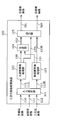
- FIG. 1 is a block diagram showing a configuration of a 3D image display system according to Embodiment 1 of the present invention.
- HDMI High-Definition Multimedia Interface
- the digital video recorder 30 converts the format of a three-dimensional image recorded on an optical disc 41 such as a BD (Blu-ray disc) and outputs the converted three-dimensional image to the digital television 20 via the HDMI cable 40.
- an optical disc 41 such as a BD (Blu-ray disc)
- the digital TV 20 converts the 3D image output from the digital video recorder 30 and the 3D image format included in the broadcast wave 42 and displays the converted image.
- the broadcast wave 42 is a terrestrial digital television broadcast, a satellite digital television broadcast, or the like.
- the digital video recorder 30 may convert the format of a three-dimensional image recorded on a recording medium other than the optical disk 41 (for example, a hard disk drive, a nonvolatile memory, or the like).
- the digital video recorder 30 may convert the format of a 3D image included in the broadcast wave 42 or a 3D image acquired via a communication network such as the Internet.
- the digital video recorder 30 may convert the format of the three-dimensional image input to an external input terminal (not shown) or the like by an external device.
- the digital television 20 may convert the format of the three-dimensional image recorded on the optical disc 41 and other recording media.
- the digital television 20 may convert the format of the 3D image acquired via a communication network such as the Internet.
- the digital television 20 may convert the format of a three-dimensional image input to an external input terminal (not shown) or the like by an external device other than the digital video recorder 30.
- the digital television 20 and the digital video recorder 30 may be connected by a standard cable other than the HDMI cable 40, or may be connected by a wireless communication network.
- the digital video recorder 30 includes an input unit 31, a decoder 32, a 3D image processing apparatus 100B, and an HDMI communication unit 33.
- the input unit 31 acquires the encoded three-dimensional image 51 recorded on the optical disc 41.
- the decoder 32 generates an input 3D image 52 by decoding the encoded 3D image 51 acquired by the input unit 31.
- the 3D image processing apparatus 100B generates an output 3D image 53 by converting the format of the input 3D image 52.
- the HDMI communication unit 33 outputs the output 3D image 53 generated by the 3D image processing apparatus 100 ⁇ / b> B to the digital television 20 via the HDMI cable 40.
- the digital video recorder 30 may store the generated output 3D image 53 in a storage unit (such as a hard disk drive and a non-volatile memory) provided in the digital video recorder 30 or attach / detach to / from the digital video recorder 30. You may record on a possible recording medium (optical disc etc.).
- a storage unit such as a hard disk drive and a non-volatile memory
- the digital television 20 includes an input unit 21, a decoder 22, an HDMI communication unit 23, a 3D image processing apparatus 100, a left screen drive unit 24L, a right screen drive unit 24R, a display panel 26, and a transmitter 27. Is provided.
- the input unit 21 acquires the encoded three-dimensional image 55 included in the broadcast wave 42.
- the decoder 22 generates an input 3D image 56 by decoding the encoded 3D image 55 acquired by the input unit 21.
- the HDMI communication unit 23 acquires the output 3D image 53 output by the HDMI communication unit 33 and outputs it as an input 3D image 57.
- the 3D image processing apparatus 100 generates an output 3D image 58 by converting the format of the input 3D image 56 or the input 3D image 57.
- the output three-dimensional image 58 includes a left screen image 58L and a right screen image 58R.
- the left screen drive unit 24L displays the left screen image 58L on the left screen 26L of the display panel 26.
- the right screen drive unit 24R displays the right screen image 58R on the right screen 26R of the display panel 26.
- the transmitter 27 controls the shutter glasses 43 using wireless communication.
- the format conversion process by the 3D image processing apparatus 100 will be described.
- the format conversion process for the input three-dimensional image 56 by the three-dimensional image processing apparatus 100 will be described as an example.
- the format conversion process for the input three-dimensional image 57 by the three-dimensional image processing apparatus 100 and the third order The format conversion process for the input three-dimensional image 52 by the original image processing apparatus 100B is the same.
- the format refers to the arrangement pattern of the left-eye image and the right-eye image in each frame (field) (hereinafter simply referred to as “arrangement pattern”), the frame rate, and the scanning method (progressive and interlaced). Race) and image size.
- the 3D image processing apparatus 100 generates the output 3D image 58 by converting any one or more of the arrangement pattern, the frame rate, the scanning method, and the image size of the input 3D image 56.
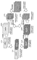
- FIG. 2A and 2B are diagrams illustrating an example of format conversion processing of the 3D image processing apparatus 100.
- FIG. 1 is a diagram illustrating an example of format conversion processing of the 3D image processing apparatus 100.
- the input three-dimensional image 56 includes a left-eye image 56l and a right-eye image 56r in each field.
- the three-dimensional image processing apparatus 100 converts the arrangement pattern of the input three-dimensional image 56, whereby an output in which frames including only the left-eye image 58l and frames including only the right-eye image 58r are alternately arranged.
- a three-dimensional image 58 is generated.
- the 3D image processing apparatus 100 converts the input 3D image 56 of 60i (interlace method with a frame rate of 60 fps) into an output 3D image 58 of 120p (progressive method with a frame rate of 120 fps).
- the shutter glasses 43 are, for example, liquid crystal shutter glasses worn by a viewer, and include a left-eye liquid crystal shutter and a right-eye liquid crystal shutter.
- the transmitter 27 controls the opening and closing of the left-eye liquid crystal shutter and the right-eye liquid crystal shutter in accordance with the display timing of the left-eye image 58l and the right-eye image 58r. Specifically, the transmitter 27 opens the left-eye liquid crystal shutter of the shutter glasses 43 and closes the right-eye liquid crystal shutter during the period in which the left-eye image 58l is displayed. Further, the transmitter 27 closes the left-eye liquid crystal shutter of the shutter glasses 43 and opens the right-eye liquid crystal shutter during the period in which the right-eye image 58r is displayed.
- the left eye image 58l and the right eye image 58r are selectively incident on the viewer's left eye and the right eye, respectively.
- the method of selectively causing the left-eye image 58l and the right-eye image 58r to enter the viewer's left eye and right eye is not limited to this method, and other methods may be used.
- the input three-dimensional image 56 includes a left-eye image 56l and a right-eye image 56r in each field.
- the three-dimensional image processing apparatus 100B converts the arrangement pattern of the input three-dimensional image 52 into an output three-dimensional image 58 in which the left-eye image 58l and the right-eye image 58r are arranged in a checkered pattern in each frame. .
- the display panel 26 includes a left-eye polarizing film formed on the left-eye pixel and a right-eye polarizing film formed on the right-eye pixel.
- Different polarized light linearly polarized light, circularly polarized light, or the like
- the shutter glasses 43 instead of the shutter glasses 43, by using polarized glasses having left-eye and right-eye polarization filters respectively corresponding to the polarized light, the left-eye image 58l and the left-eye and right-eye of the viewer are displayed.
- the right-eye image 58r can be made incident.
- the arrangement pattern of the output three-dimensional image 58 matches the arrangement pattern of the polarizing film.
- arrangement pattern of the input three-dimensional image 56 and the output three-dimensional image 58 may be any one of the following arrangement patterns.
- 3A, 3B, 4A, 4B, 5A, 5B, 6A, and 6B are diagrams showing arrangement patterns of a three-dimensional image.
- the left-eye image 60l and the right-eye image 60r are arranged side by side in the vertical direction in one frame.
- this arrangement pattern is referred to as a frame sequential.
- the left-eye image 60l and the right-eye image 60r are arranged in a horizontal direction in one frame.
- this arrangement pattern is called side-by-side.
- FIGS. 3A and 3B shows an example of a so-called full high-definition image in which one frame is composed of pixels of 1920 columns ⁇ 1080 rows, but the number of pixels included in one frame is other than this number. There may be.
- a so-called high-definition image in which one frame is composed of pixels of 1270 columns ⁇ 720 rows may be used.
- each frame includes a left-eye image 60l and a right-eye image 60r that are each compressed in half in the vertical direction or the horizontal direction, but is not compressed.
- a left-eye image 60l and a right-eye image 60r each including 1920 columns ⁇ 1080 rows may be included.
- it may be compressed at a compression rate other than 1/2, or may be compressed both in the vertical direction and in the horizontal direction.
- the 3D image scanning method may be a progressive method or an interlace method in which a top field and a bottom field are alternately arranged.
- the frame rate of the 3D image may be an arbitrary value.
- the left-eye image 60l and the right-eye image 60r are arranged in a checkered pattern.
- this arrangement pattern is referred to as a checker pattern.
- FIG. 4A, FIG. 4B, FIG. 5A, FIG. 5B, FIG. 6A and FIG. 6B only the pixels of 10 columns ⁇ 6 rows are displayed for simplicity of explanation. A number of pixels are arranged.
- the notations such as L0 and R1 shown in FIGS. 4A and 4B indicate the horizontal positions of the pixels of the left-eye image 60l and the right-eye image 60r. That is, the pixel L0 is the pixel in the 0th column of the left eye image 60l, and the pixel R1 is the pixel in the 1st column of the right eye image 60r.
- the left-eye image 60l and the right-eye image 60r may be arranged in a checkered pattern in units of one pixel, or a checkered pattern having a plurality of pixel units, for example, a group of 2 columns ⁇ 2 rows of pixels as one unit. It may be arranged in a shape.
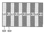
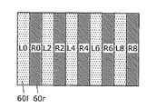
- the left-eye image 60l and the right-eye image 60r are arranged in a vertical stripe shape.
- this arrangement pattern is referred to as vertical interleaving.
- the notations such as L0 and R1 shown in FIGS. 5A and 5B indicate the horizontal positions of the pixels of the left-eye image 60l and the right-eye image 60r. That is, the pixel L0 is the pixel in the 0th column of the left eye image 60l, and the pixel R1 is the pixel in the 1st column of the right eye image 60r.
- left-eye image 60l and the right-eye image 60r may be alternately arranged for each column, or may be alternately arranged for a plurality of columns.
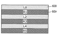
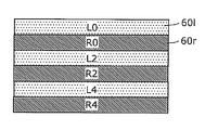
- the left-eye image 60l and the right-eye image 60r are arranged in a horizontal stripe shape.
- this arrangement pattern is referred to as line sequential.
- the notations such as L0 and R1 shown in FIGS. 6A and 6B indicate the positions of the pixels of the left-eye image 60l and the right-eye image 60r in the vertical direction. That is, the pixel L0 is the pixel in the 0th row of the left eye image 60l, and the pixel R1 is the pixel in the 1st row of the right eye image 60r.
- left-eye image 60l and the right-eye image 60r may be alternately arranged for each row, or may be alternately arranged for every plurality of rows.
- the left eye image and the right eye image may be arranged in reverse.
- FIG. 7 is a diagram illustrating an example of the left-eye image 58l and the right-eye image 58r.
- the objects included in the left-eye image 58l and the right-eye image 58r have parallax according to the distance of the object from the shooting position.
- the 3D image processing apparatus 100B included in the digital video recorder 30 when the format conversion is performed, for example, the 3D image processing apparatus 100B changes the arrangement pattern of the input 3D image 52 as shown in FIG. 2B.
- the data is converted into a predetermined arrangement pattern (for example, a checker pattern) and converted into 120p.
- the three-dimensional image processing apparatus 100 included in the digital television 20 converts the arrangement pattern of the 120p input three-dimensional image 57 (for example, the left-eye image 58l and the right-eye image 58r are alternately arranged. Only conversion).
- the 3D image processing apparatus 100B performs the format conversion shown in FIG. 2A, and the 3D image processing apparatus 100 may not perform the format conversion.
- the 3D image processing apparatus 100B may perform a part of the conversion of the arrangement pattern, the frame rate, the scanning method, and the image size, and the 3D image processing apparatus 100 may perform conversions other than the part. .
- a part of process of the three-dimensional image processing apparatus 100 and the three-dimensional image processing apparatus 100B may overlap.
- the three-dimensional image processing apparatus 100 is a composite image including two main screen images (corresponding to the first image of the present invention) and sub-screen images (corresponding to the second image of the present invention) as two two-dimensional images in one screen. And the three-dimensional image processing mode for converting the input three-dimensional image 56 or 57 in the first format into the output three-dimensional image 58 in the second format as described above.
- FIG. 8 is a diagram illustrating an operation example in the two-screen processing mode by the three-dimensional image processing apparatus 100.
- the 3D image processing apparatus 100 in the two-screen processing mode, the 3D image processing apparatus 100 generates a composite image in which reduced sub-screens are arranged on the main screen. Details of the operation in the two-screen processing mode will be described later.
- FIG. 9 is a block diagram showing a configuration of the 3D image processing apparatus 100.
- the 3D image processing apparatus 100 includes an input selection unit 101, a main screen image processing unit 102, a sub screen image processing unit 103, a combining unit 104, and an output unit 105.
- the input selection unit 101 outputs the main screen image 110 to the main screen image processing unit 102 and outputs the sub screen image 111 to the sub screen image processing unit 103 in the two-screen processing mode.
- the input selection unit 101 converts the 3D image 112 into the left screen input image 112L (corresponding to the first input image of the present invention) and the right screen input image 112R (second input image of the present invention).
- the left screen input image 112L is output to the main screen image processing unit 102
- the right screen input image 112R is output to the sub screen image processing unit 103.
- the input selection unit 101 outputs the 3D image 112 to the main screen image processing unit 102 and the sub screen image processing unit 103, respectively, and the main screen image processing unit 102 outputs the 3D image 112 from the 3D image 112.
- the left screen input image 112L may be extracted, and the sub screen image processing unit 103 may extract the right screen input image 112R from the three-dimensional image 112.
- the main screen image 110 and the sub screen image 111 are different two-dimensional images.
- the main screen image 110 and the sub screen image 111 are an image of the first channel included in the broadcast wave 42, an image of the second channel included in the broadcast wave 42, and an image acquired by the HDMI communication unit 23. Two of them are images.
- the three-dimensional image 112 is the input three-dimensional image 56 or 57 described above.
- the left screen input image 112L is an image of the left half of the 3D image 112
- the right screen input image 112R is an image of the right half of the 3D image 112.
- the main screen image processing unit 102 converts the format of the main screen image 110 output by the input selection unit 101 to thereby convert the main screen processed image 150. (Corresponding to the first processed image of the present invention) is generated.
- the main screen image processing unit 102 converts the format of the left screen input image 112L output by the input selection unit 101, thereby converting the left screen output image 153L (first output image of the present invention). Equivalent).
- the sub-screen image processing unit 103 converts the format of the sub-screen image 111 output by the input selection unit 101, thereby sub-screen processing image 151. (Corresponding to the second processed image of the present invention) is generated. Further, in the 3D image processing mode, the sub-screen image processing unit 103 converts the format of the right screen input image 112R output by the input selection unit 101, thereby converting the right screen output image 153R (second output image of the present invention). Equivalent).
- the combining unit 104 generates a composite image 152 by combining the main screen processed image 150 generated by the main screen image processing unit 102 and the sub screen processed image 151 generated by the sub screen image processing unit 103. .
- the output unit 105 divides the composite image 152 generated by the combining unit 104 into a left screen image 58L and a right screen image 58R in the two-screen processing mode.
- the output unit 105 outputs the divided left screen image 58L to the left screen drive unit 24L, and outputs the divided right screen image 58R to the right screen drive unit 24R.
- the output unit 105 outputs the left screen output image 153L generated by the main screen image processing unit 102 as the left screen image 58L to the left screen driving unit 24L, and the sub screen image processing unit 103.
- the right screen output image 153R generated by the above is output as the right screen image 58R to the right screen drive unit 24R.
- FIG. 10 is a block diagram showing the configuration of the main screen image processing unit 102 and the sub screen image processing unit 103.
- the main screen image processing unit 102 includes a main screen preprocessing unit 120 and a main screen postprocessing unit 121.
- the 3D image processing apparatus 100 further includes a memory 140 and a memory controller 141.
- the main screen pre-processing unit 120 (corresponding to the first pre-processing unit of the present invention) reduces the image size of the main screen image 110 or the left screen input image 112L and converts the scanning method, thereby converting the left screen processed image. 160L (corresponding to the third processed image of the present invention) is generated.
- the main screen preprocessing unit 120 includes a horizontal reduction unit 122, an IP conversion unit 123, and a vertical reduction unit 124.
- the horizontal reduction unit 122 reduces and outputs the horizontal image size of the main screen image 110 or the left screen input image 112L.
- the IP conversion unit 123 converts the scanning method of the image output from the horizontal reduction unit 122 from the interlace method to the progressive method (hereinafter referred to as “IP conversion”), and outputs the converted image.
- IP conversion is a process of interpolating pixels in a nonexistent row in an interlaced image.
- pixels in a non-existing row are interpolated using pixels around the same field, or the same or surrounding pixels in a field having a different field determination signal immediately or immediately after.
- which pixel is used for interpolation is determined according to the motion of the image.
- the field determination signal is a signal indicating whether the field is a top field or a bottom field.
- the vertical reduction unit 124 generates and outputs a left screen processed image 160L by reducing the image size in the vertical direction of the image output by the IP conversion unit 123.
- a method for reducing the image size a method of thinning out pixels or a method of calculating an average value of a plurality of pixels can be used.
- the order of processing by the horizontal reduction unit 122, the IP conversion unit 123, and the vertical reduction unit 124 illustrated in FIG. 10 is an example, and the processing by each processing unit may be performed in an arbitrary order.
- the memory controller 141 writes and reads 149 data to and from the memory.
- the main screen preprocessing unit 120 stores the generated left screen processed image 160L in the memory 140 via the memory controller 141.
- the main screen post-processing unit 121 (corresponding to the first post-processing unit of the present invention) includes at least one of the left screen processed image 160L and the right screen processed image 160R stored in the memory 140 via the memory controller 141.
- the left screen processed image 161L (corresponding to the fifth processed image of the present invention) is read.
- the left screen processed image 161L includes pixels corresponding to the left screen 26L of the display panel 26 among the pixels included in the left screen processed image 160L and the right screen processed image 160R stored in the memory 140. .
- the main screen post-processing unit 121 generates the main screen processed image 150 or the left screen output image 153L by enlarging the image size of the left screen processed image 161L and converting the arrangement pattern and the frame rate.
- the main screen post-processing unit 121 includes a pattern conversion unit 125, a vertical enlargement unit 126, and a horizontal enlargement unit 127.
- the pattern conversion unit 125 converts the arrangement pattern and frame rate of the left screen processed image 161L and outputs the result.
- the pattern conversion unit 125 may convert the arrangement pattern and the frame rate after reading the left screen processed image 161L, or read the pixels by reading out the left screen processed image 161L in the arrangement order. At the same time, pattern conversion and frame rate conversion may be performed.
- the vertical enlargement unit 126 enlarges and outputs the image size in the vertical direction of the image output by the pattern conversion unit 125.
- the horizontal enlargement unit 127 enlarges and outputs the image size in the horizontal direction of the image output by the vertical enlargement unit 126.
- a method for enlarging the image size a method of simply copying pixels or a method of interpolating nonexistent pixels can be used.
- the order of processing by the pattern conversion unit 125, the vertical enlargement unit 126, and the horizontal enlargement unit 127 illustrated in FIG. 10 is an example, and the processing by each processing unit may be performed in an arbitrary order.
- the configuration of the sub-screen image processing unit 103 will be described. Note that the configuration of the sub-screen image processing unit 103 is the same as that of the main screen image processing unit 102.
- the sub-screen image processing unit 103 includes a sub-screen pre-processing unit 130 and a sub-screen post-processing unit 131.
- the sub-screen pre-processing unit 130 (corresponding to the second pre-processing unit of the present invention) reduces the image size of the sub-screen image 111 or the right screen input image 112R and performs IP conversion so that the right screen processed image 160R ( Corresponding to the fourth processed image of the present invention).
- the sub-screen preprocessing unit 130 includes a horizontal reduction unit 132, an IP conversion unit 133, and a vertical reduction unit 134.
- the horizontal reduction unit 132 reduces and outputs the horizontal image size of the sub-screen image 111 or the right screen input image 112R.
- the IP conversion unit 133 performs IP conversion on the image output by the horizontal reduction unit 132 and outputs it.
- the vertical reduction unit 134 generates and outputs the right screen processed image 160R by reducing the image size in the vertical direction of the image output by the IP conversion unit 133.
- the order of processing by the horizontal reduction unit 132, the IP conversion unit 133, and the vertical reduction unit 134 illustrated in FIG. 10 is an example, and the processing by each processing unit may be performed in an arbitrary order.
- the sub-screen preprocessing unit 130 stores the generated right screen processed image 160R in the memory 140 via the memory controller 141.
- the sub-screen post-processing unit 131 (corresponding to the second post-processing unit of the present invention) includes at least one of the left screen processed image 160L and the right screen processed image 160R stored in the memory 140 via the memory controller 141.
- the right screen processed image 161R (corresponding to the sixth processed image of the present invention) is read.
- the right screen processed image 161R is the right screen output image 153R (the right screen 26R of the display panel 26) among the pixels included in the left screen processed image 160L and the right screen processed image 160R stored in the memory 140. ).
- the sub-screen post-processing unit 131 generates the sub-screen processed image 151 or the right screen output image 153R by increasing the image size of the right screen processed image 160R and converting the arrangement pattern and the frame rate.
- the sub-screen post-processing unit 131 includes a pattern conversion unit 135, a vertical enlargement unit 136, and a horizontal enlargement unit 137.
- the pattern conversion unit 135 converts and outputs the arrangement pattern and frame rate of the right screen processed image 161R.
- the pattern conversion unit 135 may convert the arrangement pattern and the frame rate after reading out the right screen processed image 161R, or read out the pixels by reading out the right screen processed image 161R in the arrangement order. At the same time, pattern conversion and frame rate conversion may be performed.
- the vertical enlargement unit 136 enlarges and outputs the image size in the vertical direction of the image output by the pattern conversion unit 135.
- the horizontal enlargement unit 137 enlarges and outputs the image size in the horizontal direction of the image output by the vertical enlargement unit 136.
- the order of processing by the pattern conversion unit 135, the vertical enlargement unit 136, and the horizontal enlargement unit 137 shown in FIG. 10 is an example, and the processing by each processing unit may be performed in an arbitrary order.
- the main screen image 110 and the sub screen image 111 are 480i and the frame rate is 60 fps.
- the input selection unit 101 outputs the main screen image 110 to the main screen image processing unit 102 and outputs the sub screen image 111 to the sub screen image processing unit 103.
- the main screen image processing unit 102 performs IP conversion of the main screen image 110 and expands the image size from high definition to full high definition, thereby generating a main screen processed image 150 of 1080p and 60 fps.
- the IP conversion unit 123 generates a converted image of 720p and 60 fps by performing IP conversion on the main screen image 110.
- the vertical enlargement unit 126 and the horizontal enlargement unit 127 generate the 1080p and 60 fps main screen processed image 150 by enlarging the converted image.
- the sub-screen image processing unit 103 converts the scanning method of the sub-screen image 111 from the interlace method to the progressive method and reduces the image size to generate, for example, a sub-screen processed image 151 of 400 p and 60 fps. To do.
- the horizontal reduction unit 132 reduces the horizontal image size of the sub-screen image 111
- the IP conversion unit 133 converts the reduced image scanning method from the interlace method to the progressive method.
- 720p and 60 fps converted images are generated.
- the vertical reduction unit 134 generates a 400p and 60 fps sub-screen processed image 151 by reducing the vertical image size of the converted image.
- the synthesizing unit 104 synthesizes the main screen processed image 150 generated by the main screen image processing unit 102 and the sub-screen processed image 151 generated by the sub-screen image processing unit 103, thereby 1080p and 60fps.
- the composite image 152 is generated.
- the output unit 105 divides the combined image 152 generated by the combining unit 104 into a left screen image 58L and a right screen image 58R.
- the output unit 105 outputs the divided left screen image 58L to the left screen drive unit 24L, and outputs the divided right screen image 58R to the right screen drive unit 24R.
- the 3D image processing apparatus 100 can generate a composite image in which a reduced sub-screen is displayed on the main screen.
- the main screen image processing unit 102 performs image size reduction processing. Is called.
- the main screen image processing unit 102 performs image size reduction processing.
- the 3D image processing apparatus 100 generates a composite image in which the main screen and the sub screen are arranged on the divided sub screen instead of generating a composite image in which the sub screen is superimposed on the main screen.
- a mode for generating a composite image in which the sub screen is superimposed on the main screen and a mode for generating a composite image in which the main screen and the sub screen are arranged on the divided sub screen.
- the main screen preprocessing unit 120 once reduces the image size of the main screen image 110, and then the main screen postprocessing unit 121.
- the image size may be increased so that the reduced image size is restored to the original image size.
- the main screen preprocessing unit 120 sets the image size of the main screen image 110. May be reduced to 1 ⁇ 2 in the vertical direction, and the main screen post-processing unit 121 may enlarge the reduced image size twice in the vertical direction.
- the amount of data stored in the memory 140 can be reduced, the capacity of the memory 140 can be reduced. Furthermore, the amount of processing in the IP conversion unit 123, the pattern conversion unit 125, and the like can be reduced.
- the sub-screen pre-processing unit 130 once sets the sub-screen image 111 and the display image size of the display panel 26 regardless of the image size.
- the sub-screen post-processing unit 131 may enlarge the image size so that the reduced image size is restored to the original image size.
- main screen image processing unit 102 and the sub screen image processing unit 103 may perform processing for increasing or decreasing the frame rate.
- the 3D image processing apparatus 100 has a normal mode in which only one normal image is displayed on one screen in addition to the two-screen processing mode and the three-dimensional image processing mode.
- the main screen image processing unit 102 performs format conversion of the one image.
- FIG. 11 to FIG. 16 are diagrams showing an operation example in the 3D image processing mode by the 3D image processing apparatus 100.
- the three-dimensional image 112 is a full-size 1080i frame sequential and 60 fps image. That is, the three-dimensional image 112 includes a left eye image 60l of 1080i (1920 columns ⁇ 540 rows) and a right eye image 60r of 1080i (1920 columns ⁇ 540 rows) in one field.
- the dot clock of the three-dimensional image 112 is 148.5 MHz.
- the dot clock is a value represented by the product of the image size (number of rows ⁇ number of columns) and the frame rate. That is, the higher the dot clock, the shorter the time that can be used for processing one pixel, in other words, the larger the amount of data to be processed per unit time.
- the display panel 26 displays 1080p and 120 fps images in which the left-eye images 60l and the right-eye images 60r are alternately arranged.
- the input selection unit 101 divides the three-dimensional image 112 into a left screen input image 112L and a right screen input image 112R, and outputs the left screen input image 112L to the main screen image processing unit 102.
- the input image 112R is output to the sub-screen image processing unit 103.
- the left screen input image 112L and the right screen input image 112R are half the image size of the three-dimensional image 112. Therefore, the dot clock of the left screen input image 112L and the right screen input image 112R is 74.25 MHz which is half of the dot clock of the three-dimensional image 112.
- the left screen input image 112L includes a left eye image 60l of 1080i / 2 (960 columns ⁇ 540 rows) and a right eye image 60r of 1080i / 2 (960 columns ⁇ 540 rows) in one field.
- the right screen input image 112R includes a left eye image 60l of 1080i / 2 (960 columns ⁇ 540 rows) and a right eye image 60r of 1080i / 2 (960 columns ⁇ 540 rows) in one field.
- the image sizes of the left screen input image 112L and the right screen input image 112R are 960 columns ⁇ 1080 rows, respectively.
- the main screen preprocessing unit 120 performs I / P conversion on the left screen input image 112L to generate a left screen processed image 160L of 1080p and 60 fps.
- This I / P conversion doubles the vertical image size. Therefore, the dot clock of the left screen processed image 160L is 148.5 MHz, which is twice that of the left screen input image 112L.
- the left screen processed image 160L includes a left-eye image 60l of 1080p / 2 (960 columns ⁇ 1080 rows) and a right-eye image 60r of 1080p / 2 (960 columns ⁇ 1080 rows) per frame. including. Therefore, the image size of the left screen processed image 160L is 960 columns ⁇ 2160L rows.
- the main screen preprocessing unit 120 stores the left screen processed image 160L in the memory 140 via the memory controller 141.
- the main screen post-processing unit 121 reads the left screen processed image 160L via the memory controller 141.
- the main screen post-processing unit 121 performs 1080p / 2 (960) in which the left-eye image 60l and the right-eye image 60r are alternately arranged by performing pattern conversion and double speeding of the left-screen processed image 160L.
- Column x 1080 rows) and 120 fps left screen output image 153L is generated.
- the dot clock of the left screen output image 153L is 148.5 MHz, which is the same as the dot clock of the left screen processed image 160L.
- the sub screen image processing unit 103 performs the same processing as the main screen image processing unit 102 on the right screen input image 112R.
- the sub-screen preprocessing unit 130 performs I / P conversion on the right screen input image 112R to generate a 1080p and 60 fps right screen processed image 160R.
- This I / P conversion doubles the vertical image size. Therefore, the dot clock of the right screen processed image 160R is 148.5 MHz, which is twice that of the right screen input image 112R.
- the right screen processed image 160R includes a left-eye image 60l of 1080p / 2 (960 columns ⁇ 1080 rows) and a right-eye image 60r of 1080p / 2 (960 columns ⁇ 1080 rows) per frame. including. Therefore, the image size of the right screen processed image 160R is 960 columns ⁇ 2160 L rows.
- the sub-screen preprocessing unit 130 stores the right screen processed image 160R in the memory 140 via the memory controller 141.
- the sub-screen post-processing unit 131 reads the right-screen processed image 160R via the memory controller 141.
- the sub-screen post-processing unit 131 performs 1080p / 2 (960) in which the left-eye image 60l and the right-eye image 60r are alternately arranged by performing pattern conversion and double speeding of the right-screen processed image 160R.
- the dot clock of the right screen output image 153R is 148.5 MHz, which is the same as the dot clock of the right screen processed image 160R.
- the output unit 105 outputs the left screen output image 153L generated by the main screen image processing unit 102 to the left screen drive unit 24L as the left screen image 58L, and the right screen generated by the sub screen image processing unit 103.
- the output image 153R is output to the right screen drive unit 24R as the right screen image 58R.
- the left screen drive unit 24L displays the left screen image 58L on the left screen 26L of the display panel 26.
- the right screen drive unit 24R displays the right screen image 58R on the right screen 26R of the display panel 26.
- the main screen image processing unit 102 and the sub screen image processing unit 103 each process an image with a maximum dot clock of 148 and 5 MHz.
- an image with a dot clock of 297 MHz can be generated.
- the three-dimensional image 112 is a full-size 720p frame sequential and 60 fps image. That is, the 3D image 112 includes a left-eye image 60l of 720p (1270 columns ⁇ 720 rows) and a right-eye image 60r of 720p (1270 columns ⁇ 720 rows) in one frame. That is, the dot clock of the three-dimensional image 112 is 148.5 MHz.
- the display panel 26 displays 1080p and 120 fps images in which the left-eye images 60l and the right-eye images 60r are alternately arranged.
- the input selection unit 101 divides the three-dimensional image 112 into a left screen input image 112L and a right screen input image 112R, and outputs the left screen input image 112L to the main screen image processing unit 102.
- the input image 112R is output to the sub-screen image processing unit 103.
- the left screen input image 112L and the right screen input image 112R are half the image size of the three-dimensional image 112. Therefore, the dot clock of the left screen input image 112L and the right screen input image 112R is 74.25 MHz which is half of the dot clock of the three-dimensional image 112.
- the left screen input image 112L includes a left-eye image 60l of 720p / 2 (635 columns ⁇ 720 rows) and a right-eye image 60r of 720p / 2 (635 columns ⁇ 720 rows) per frame.
- the right screen input image 112R includes a left-eye image 60l of 720p / 2 (635 columns ⁇ 720 rows) and a right-eye image 60r of 720p / 2 (635 columns ⁇ 720 rows) in one frame.
- the image sizes of the left screen input image 112L and the right screen input image 112R are 635 columns ⁇ 1440 rows, respectively.
- the main screen preprocessing unit 120 stores the left screen input image 112L (left screen processed image 160L) in the memory 140 via the memory controller 141.
- the main screen post-processing unit 121 reads the left screen processed image 160L via the memory controller 141. At this time, the main screen post-processing unit 121 performs pattern conversion and double speeding of the left screen processed image 160L, so that the left eye image 60l and the right eye image 60r are alternately arranged 720p / 2 (635 Column 720 rows) and 120 fps left screen processed image 163L is generated.
- the dot clock of the left screen processed image 163L is 74.25 MHz, which is the same as the dot clock of the left screen processed image 160L.
- the main screen post-processing unit 121 enlarges the image size of the left screen processed image 163L to thereby arrange 1080p / 2 (960 rows ⁇ 960 images) in which the left eye image 60l and the right eye image 60r are alternately arranged. 1080 line) and 120 fps left screen output image 153L.
- This enlargement process doubles the image size. Therefore, the dot clock of the left screen output image 153L is 148.5 MHz, which is twice the dot clock of the left screen processed image 163L.
- the sub-screen image processing unit 103 performs pattern conversion and double speed conversion of the right screen processed image 160R so that the left-eye image 60l and the right-eye image 60r alternate.
- 720p / 2 (635 columns ⁇ 720 rows) and 120 fps right screen processed image 163R are generated.
- the sub-screen post-processing unit 131 generates a right screen output image 153R of 1080p / 2 (960 columns ⁇ 1080 rows) and 120 fps by enlarging the image size of the right screen processed image 163R.
- the output unit 105 outputs the left screen output image 153L generated by the main screen image processing unit 102 to the left screen drive unit 24L as the left screen image 58L, and the right screen generated by the sub screen image processing unit 103.
- the output image 153R is output to the right screen drive unit 24R as the right screen image 58R.
- the left screen drive unit 24L displays the left screen image 58L on the left screen 26L of the display panel 26.
- the right screen drive unit 24R displays the right screen image 58R on the right screen 26R of the display panel 26.
- the main screen post-processing unit 121 cannot generate the left screen output image 153L from only the left screen processed image 160L generated by the main screen pre-processing unit 120. Therefore, the main screen post-processing unit 121 uses the left screen processed image 160L generated by the main screen pre-processing unit 120 and the right screen processed image 160R generated by the sub-screen pre-processing unit 130 to output the left screen. An image 153L is generated.
- the sub-screen post-processing unit 131 cannot generate the right-screen output image 153R only from the right-screen processed image 160R generated by the sub-screen pre-processing unit 130. Therefore, the sub-screen post-processing unit 131 uses the left-screen processed image 160L generated by the main-screen pre-processing unit 120 and the right-screen processed image 160R generated by the sub-screen pre-processing unit 130 to output the right screen. An image 153R is generated.
- the three-dimensional image 112 is a full-size 1080i side-by-side and 60 fps image. That is, the three-dimensional image 112 includes a left eye image 60l of 1080i (1920 columns ⁇ 540 rows) and a right eye image 60r of 1080i (1920 columns ⁇ 540 rows) in one field. That is, the dot clock of the three-dimensional image 112 is 148.5 MHz.
- the display panel 26 displays 1080p and 120 fps images in which the left-eye images 60l and the right-eye images 60r are alternately arranged.
- the input selection unit 101 divides the three-dimensional image 112 into a left screen input image 112L and a right screen input image 112R, and outputs the left screen input image 112L to the main screen image processing unit 102.
- the input image 112R is output to the sub-screen image processing unit 103.
- the left screen input image 112L and the right screen input image 112R are half the image size of the three-dimensional image 112. Therefore, the dot clock of the left screen input image 112L and the right screen input image 112R is 74.25 MHz which is half of the dot clock of the three-dimensional image 112.
- the left screen input image 112L includes a left-eye image 60l of 1080i (1920 columns ⁇ 540 rows) in one field.
- the right screen input image 112R includes a 1080i (1920 columns ⁇ 540 rows) right-eye image 60r in one field. That is, the image sizes of the left screen input image 112L and the right screen input image 112R are 1920 columns ⁇ 540 rows, respectively.
- the main screen preprocessing unit 120 performs I / P conversion on the left screen input image 112L to generate a left screen processed image 160L of 1080p and 60 fps.
- This I / P conversion doubles the vertical image size. Therefore, the dot clock of the left screen processed image 160L is 148.5 MHz, which is twice that of the left screen input image 112L.
- the left screen processed image 160L includes a left-eye image 60l of 1080p (1920 columns ⁇ 1080 rows) in one frame. Therefore, the image size of the left screen processed image 160L is 1920 columns ⁇ 1080 rows.
- the main screen preprocessing unit 120 stores the left screen processed image 160L in the memory 140 via the memory controller 141.
- the sub-screen pre-processing unit 130 generates a 1080p and 60 fps right-screen processed image 160R by performing I / P conversion on the right-screen input image 112R.
- This I / P conversion doubles the vertical image size. Therefore, the dot clock of the right screen processed image 160R is 148.5 MHz, which is twice that of the right screen input image 112R.
- the right screen processed image 160R includes a right-eye image 60r of 1080p (1920 columns ⁇ 1080 rows) in one frame. Therefore, the image size of the right screen processed image 160R is 1920 columns ⁇ 1080 rows.
- the sub-screen preprocessing unit 130 stores the right screen processed image 160R in the memory 140 via the memory controller 141.
- the main screen post-processing unit 121 via the memory controller 141, among the plurality of pixels included in the left screen processed image 160L and the right screen processed image 160R, a plurality of pixels corresponding to the left screen 26L of the display panel 26.
- a left screen processed image 161L including pixels is read out.
- the main screen post-processing unit 121 performs 1080p / 2 (960 columns) in which the left-eye image 60l and the right-eye image 60r are alternately arranged by performing pattern conversion and double speeding of the left-screen processed image 161L. ⁇ 1080 lines) and a left screen output image 153L of 120 fps is generated.
- the main screen post-processing unit 121 reads the left half of the left screen processed image 160L and the left half of the right screen processed image 160R, and also reads the left half of the read left screen processed image 160L and the right screen processed image 160R.
- the left screen output image 153L is generated by alternately arranging the left half of the left screen.
- the dot clock of the left screen output image 153L is 148.5 MHz, which is the same as the dot clock of the left screen processed image 160L.
- the sub-screen post-processing unit 131 is connected to the display panel 26 among a plurality of pixels included in the left screen processed image 160L and the right screen processed image 160R via the memory controller 141.
- a right screen processed image 161R including a plurality of pixels corresponding to the right screen 26R is read out.
- the sub-screen post-processing unit 131 performs 1080p / 2 (960 columns) in which the left-eye image 60l and the right-eye image 60r are alternately arranged by performing pattern conversion and double speeding of the right-screen processed image 161R.
- X 1080 lines) and 120 fps right screen output image 153R is generated.
- the sub-screen post-processing unit 131 reads the right half of the left screen processed image 160L and the right half of the right screen processed image 160R, and the right half of the read left screen processed image 160L and the right screen processed image 160R.
- the right screen output image 153R is generated by alternately arranging the right half of the right screen.
- the dot clock of the right screen output image 153R is 148.5 MHz, which is the same as the dot clock of the left screen processed image 160L.
- the output unit 105 outputs the left screen output image 153L generated by the main screen image processing unit 102 to the left screen drive unit 24L as the left screen image 58L, and the right screen generated by the sub screen image processing unit 103.
- the output image 153R is output to the right screen drive unit 24R as the right screen image 58R.
- the left screen drive unit 24L displays the left screen image 58L on the left screen 26L of the display panel 26.
- the right screen drive unit 24R displays the right screen image 58R on the right screen 26R of the display panel 26.
- the three-dimensional image 112 is a full-size 720p side-by-side and 60 fps image. That is, the 3D image 112 includes a left-eye image 60l of 720p (1270 columns ⁇ 720 rows) and a right-eye image 60r of 720p (1270 columns ⁇ 720 rows) in one frame. That is, the dot clock of the three-dimensional image 112 is 148.5 MHz.
- the display panel 26 displays 1080p and 120 fps images in which the left-eye images 60l and the right-eye images 60r are alternately arranged.
- the input selection unit 101 divides the three-dimensional image 112 into a left screen input image 112L and a right screen input image 112R, and outputs the left screen input image 112L to the main screen image processing unit 102.
- the input image 112R is output to the sub-screen image processing unit 103.
- the left screen input image 112L and the right screen input image 112R are half the image size of the three-dimensional image 112. Therefore, the dot clock of the left screen input image 112L and the right screen input image 112R is 74.25 MHz which is half of the dot clock of the three-dimensional image 112.
- the left screen input image 112L includes a left-eye image 60l of 720p (1270 columns ⁇ 720 rows) in one frame.
- the right screen input image 112R includes a right-eye image 60r of 720p (1270 columns ⁇ 720 rows) in one frame. That is, the image sizes of the left screen input image 112L and the right screen input image 112R are 1270 columns ⁇ 720 rows, respectively.
- the main screen preprocessing unit 120 stores the left screen input image 112L (left screen processed image 160L) in the memory 140 via the memory controller 141.
- the sub-screen pre-processing unit 130 stores the right screen input image 112R (right screen processed image 160R) in the memory 140 via the memory controller 141.
- the main screen post-processing unit 121 via the memory controller 141, among the plurality of pixels included in the left screen processed image 160L and the right screen processed image 160R, a plurality of pixels corresponding to the left screen 26L of the display panel 26.
- a left screen processed image 161L including pixels is read out.
- the main screen post-processing unit 121 performs pattern conversion and double speed conversion of the left screen processed image 161L, thereby 720p / 2 (635 columns) in which the left eye image 60l and the right eye image 60r are alternately arranged. ⁇ 720 lines) and 120 fps left screen processed image 163L is generated.
- the main screen post-processing unit 121 reads the left half of the left screen processed image 160L and the left half of the right screen processed image 160R, and also reads the left half of the read left screen processed image 160L and the right screen processed image 160R.
- the left screen output image 153L is generated by alternately arranging the left half of the left screen.
- the dot clock of the left screen processed image 163L is 74.25 MHz, which is the same as the dot clock of the left screen processed image 160L.
- the main screen post-processing unit 121 enlarges the image size of the left screen processed image 163L to thereby arrange 1080p / 2 (960 rows ⁇ 960 images) in which the left eye image 60l and the right eye image 60r are alternately arranged. 1080 line) and 120 fps left screen output image 153L.
- This enlargement process doubles the image size. Therefore, the dot clock of the left screen output image 153L is 148.5 MHz, which is twice the dot clock of the left screen processed image 163L.
- the sub-screen post-processing unit 131 performs the same processing as the main-screen post-processing unit 121, whereby 1080p / 2 (960 rows ⁇ 960) in which the left-eye image 60l and the right-eye image 60r are alternately arranged. 1080 line) and 120 fps right screen output image 153R.
- the output unit 105 outputs the left screen output image 153L generated by the main screen image processing unit 102 to the left screen drive unit 24L as the left screen image 58L, and the right screen generated by the sub screen image processing unit 103.
- the output image 153R is output to the right screen drive unit 24R as the right screen image 58R.
- the left screen drive unit 24L displays the left screen image 58L on the left screen 26L of the display panel 26.
- the right screen drive unit 24R displays the right screen image 58R on the right screen 26R of the display panel 26.
- the three-dimensional image 112 is a 1080i frame sequential and 120 fps image. That is, the three-dimensional image 112 includes a left eye image 60l of 1080i (1920 columns ⁇ 540 rows) and a right eye image 60r of 1080i (1920 columns ⁇ 540 rows) in one field. That is, the dot clock of the three-dimensional image 112 is 148.5 MHz.
- the display panel 26 displays 1080p and 120 fps images in which the left-eye images 60l and the right-eye images 60r are alternately arranged.
- the input selection unit 101 divides the three-dimensional image 112 into a left screen input image 112L and a right screen input image 112R, and outputs the left screen input image 112L to the main screen image processing unit 102.
- the input image 112R is output to the sub-screen image processing unit 103.
- the left screen input image 112L and the right screen input image 112R are half the image size of the three-dimensional image 112. Therefore, the dot clock of the left screen input image 112L and the right screen input image 112R is 74.25 MHz which is half of the dot clock of the three-dimensional image 112.
- the left screen input image 112L includes a left eye image 60l of 1080i / 2 (960 columns ⁇ 540 rows) and a right eye image 60r of 1080i / 2 (960 columns ⁇ 540 rows) in one field.
- the right screen input image 112R includes a left eye image 60l of 1080i / 2 (960 columns ⁇ 540 rows) and a right eye image 60r of 1080i / 2 (960 columns ⁇ 540 rows) in one field.
- the image sizes of the left screen input image 112L and the right screen input image 112R are 480 columns ⁇ 1080 rows, respectively.
- the main screen preprocessing unit 120 performs I / P conversion on the left screen input image 112L to generate a left screen processed image 160L of 1080p / 2 and 120 fps.
- This I / P conversion doubles the vertical image size. Therefore, the dot clock of the left screen processed image 160L is 148.5 MHz, which is twice that of the left screen input image 112L.
- the left screen processed image 160L includes a left-eye image 60l of 1080p / 2 (960 columns ⁇ 1080 rows) and a right-eye image 60r of 1080p / 2 (960 columns ⁇ 1080 rows) per frame. including. Therefore, the image size of the left screen processed image 160L is 960 columns ⁇ 2160L rows.
- the main screen preprocessing unit 120 stores the left screen processed image 160L in the memory 140 via the memory controller 141.
- the main screen post-processing unit 121 reads the left screen processed image 160L via the memory controller 141. At this time, the main screen post-processing unit 121 performs 1080p / 2 (960 columns ⁇ 1080) in which the left-eye image 60l and the right-eye image 60r are alternately arranged by performing pattern conversion of the left-screen processed image 160L. Row) and a left screen processed image 163L of 120 fps is generated. For example, the main screen post-processing unit 121 generates a left screen processed image 163L that alternately includes only one of the left eye image 60l and the right eye image 60r included in each frame of the left screen processed image 160L.
- the dot clock of the left screen output image 153L is 74.25 MHz which is half of the dot clock of the left screen processed image 160L.
- the main screen post-processing unit 121 enlarges the image size of the left screen processed image 163L to thereby arrange 1080p / 2 (960 rows ⁇ 960 images) in which the left eye image 60l and the right eye image 60r are alternately arranged. 1080 line) and 120 fps left screen output image 153L.
- This enlargement process doubles the image size. Therefore, the dot clock of the left screen output image 153L is 148.5 MHz, which is twice the dot clock of the left screen processed image 163L.
- the sub-screen image processing unit 103 performs the same processing as the main screen image processing unit 102 on the right screen input image 112R, thereby alternately arranging the left-eye image 60l and the right-eye image 60r.
- the left screen output image 153L of 1080p / 2 (960 columns ⁇ 1080 rows) and 120 fps is generated.
- the output unit 105 outputs the left screen output image 153L generated by the main screen image processing unit 102 to the left screen drive unit 24L as the left screen image 58L, and the right screen generated by the sub screen image processing unit 103.
- the output image 153R is output to the right screen drive unit 24R as the right screen image 58R.
- the left screen drive unit 24L displays the left screen image 58L on the left screen 26L of the display panel 26.
- the right screen drive unit 24R displays the right screen image 58R on the right screen 26R of the display panel 26.
- the main screen image processing unit 102 and the sub screen image processing unit 103 each process an image with a maximum dot clock of 148 and 5 MHz.
- an image with a dot clock of 297 MHz can be generated.
- the three-dimensional image 112 is a full-size 1080i side-by-side and 60 fps image as in the example shown in FIG.
- the display panel 26 displays line sequential 1080p and 60 fps images.
- the main screen post-processing unit 121 includes a plurality of pixels corresponding to the left screen 26L of the display panel 26 among the plurality of pixels included in the left screen processed image 160L and the right screen processed image 160R via the memory controller 141.
- a left screen processed image 161L including pixels is read out.
- the main screen post-processing unit 121 performs 1080p / 2 (960 columns ⁇ 1080 rows) in which the left-eye image 60l and the right-eye image 60r are alternately arranged by performing pattern conversion of the left-screen processed image 161L. ) And a left screen output image 153L of 60 fps is generated.
- the main screen post-processing unit 121 reads the left half of the left screen processed image 160L and the left half of the right screen processed image 160R, and also reads the left half of the read left screen processed image 160L and the right screen processed image 160R.
- the pattern conversion is performed by arranging the left half of the two in a horizontal stripe shape.
- the dot clock of the left screen output image 153L is 74.25 MHz which is half of the dot clock of the left screen processed image 160L.
- the sub-screen post-processing unit 131 performs the same processing as the main-screen post-processing unit 121, whereby 1080p / 2 (960 rows ⁇ 960) in which the left-eye image 60l and the right-eye image 60r are alternately arranged. 1080 lines) and 60 fps right screen output image 153R.
- the output unit 105 outputs the left screen output image 153L generated by the main screen image processing unit 102 to the left screen drive unit 24L as the left screen image 58L, and outputs the right screen output generated by the sub screen image processing unit 103.
- the image 153R is output to the right screen drive unit 24R as the right screen image 58R.
- the left screen drive unit 24L displays the left screen image 58L on the left screen 26L of the display panel 26.
- the right screen drive unit 24R displays the right screen image 58R on the right screen 26R of the display panel 26.
- the arrangement pattern of the three-dimensional image 112 may be any of the patterns shown in FIGS. 3A, 3B, 4A, 4B, 5A, 5B, 6A, and 6B.
- the arrangement patterns of the left screen output image 153L and the right screen output image 153R are shown in FIGS. 3A, 3B, 4A, 4B, 5A, 5B, 6A, and 6A. Any of the patterns shown in FIG. 6B may be used.
- the scanning method, frame rate, and image size of the three-dimensional image 112, the left screen output image 153L, and the right screen output image 153R may be other than those described above.
- the order of the image size reduction, image size enlargement, IP conversion, pattern conversion, and frame rate conversion processing described above is an example, and these processing may be performed in an arbitrary order.
- the main screen image processing unit 102 and the sub screen The image processing unit 103 performs image size reduction processing.
- the main screen preprocessing unit 120 temporarily sets the left eye image 60l and the right eye image 60r included in the three-dimensional image 112 to the left regardless of the image size of the left eye image 60r and the display image size of the display panel 26.
- the main screen post-processing unit 121 may increase the image size so that the reduced image size is restored to the original image size.
- the main screen pre-processing unit 120 reduces the image size of the left screen input image 112L to 1 ⁇ 2 in the vertical direction, and the main screen post-processing unit 121 increases the reduced image size by two times in the vertical direction. May be.
- the amount of data stored in the memory 140 can be reduced, the capacity of the memory 140 can be reduced. Furthermore, the amount of processing in the IP conversion unit 123, the pattern conversion unit 125, and the like can be reduced.
- the 3D image processing apparatus 100 divides the 3D image 112 into the left screen input image 112L and the right screen input image 112R, and the left screen input image 112L. Processing is performed by the main screen image processing unit 102, and the right screen input image 112 ⁇ / b> R is processed by the sub screen image processing unit 103. By performing such parallel processing, the processing capabilities of the main screen image processing unit 102 and the sub screen image processing unit 103 can be halved compared to the case where the three-dimensional image 112 is processed by one image processing unit.
- the 3D image processing apparatus 100 uses the main screen image processing unit 102 that processes the main screen image and the sub screen image processing unit 103 that processes the sub screen image for the parallel processing in the two-screen processing mode.
- the 3D image processing apparatus 100 according to Embodiment 1 of the present invention can generate a high-quality 3D image while suppressing an increase in cost.
- the processing capability of the sub-screen image processing unit 103 is lower than the processing capability of the main screen image processing unit 102. In such a case, there is a difference in image quality between the left screen output image 153L and the right screen output image 153R. In order to avoid this, the processing capability of the main screen image processing unit 102 may be matched with the processing capability of the sub-screen image processing unit 103. Thereby, although the image quality of the left screen output image 153L is reduced, the unevenness of the image quality between the left screen output image 153L and the right screen output image 153R can be eliminated.
- the processing capability of the sub-screen image processing unit 103 may be the same as that of the main screen image processing unit 102. In this case, it is necessary to increase the processing capability of the sub-screen image processing unit 103 compared to the conventional image processing device, but the cost of the three-dimensional image processing device 100 is lower than when a new image processing unit is added. Increase can be suppressed.
- Embodiment 1 the description which overlaps with Embodiment 1 is abbreviate
- FIG. 17 is a block diagram showing configurations of the main screen image processing unit 102 and the sub screen image processing unit 103 according to Embodiment 2 of the present invention.
- symbol is attached
- the configuration of the 3D image processing apparatus 100 according to Embodiment 2 of the present invention is the same as that shown in FIG.
- the 3D image processing apparatus 100 according to Embodiment 2 of the present invention differs from the 3D image processing apparatus 100 according to Embodiment 1 in the following points.
- the input selection unit 101 outputs the 3D image 112 to the main screen image processing unit 102 in the 3D image processing mode.
- the main screen preprocessing unit 120 performs horizontal image size reduction and IP conversion on the three-dimensional image 112 in the three-dimensional image processing mode, and then outputs the processed image to the left screen input image 162L.
- the image is divided into the right screen input image 162R.
- the main screen preprocessing unit 120 generates the left screen processed image 160L by reducing the image size in the vertical direction on the divided left screen input image 162L.
- the sub-screen preprocessing unit 130 generates the right screen processed image 160R by reducing the vertical image size of the divided right screen input image 162R in the three-dimensional image processing mode.
- FIG. 18 is a diagram illustrating an operation example in the 3D image processing mode by the 3D image processing apparatus 100 according to Embodiment 2 of the present invention.
- the main screen preprocessing unit 120 in the 3D image processing mode, the main screen preprocessing unit 120 generates a converted image 162 by performing I / P conversion on the 3D image 112. At the same time, the converted image 162 is divided into a left screen input image 162L and a right screen input image 162R.
- the three-dimensional image 112 is a full-size 1080i frame sequential and 60 fps image. That is, the three-dimensional image 112 includes a left-eye image 60l of 1080i (1920 columns ⁇ 540 rows) and a right-eye image 60r of 1080i (1920 columns ⁇ 540 rows) in one frame. That is, the dot clock of the three-dimensional image 112 is 148.5 MHz.
- the display panel 26 displays 1080p and 120 fps images in which the left-eye images 60l and the right-eye images 60r are alternately arranged.
- the input selection unit 101 outputs the three-dimensional image 112 to the main screen image processing unit 102.
- the main screen preprocessing unit 120 performs I / P conversion of the three-dimensional image 112 to generate a 1080p ⁇ 2 and 60 fps converted image 162.
- This I / P conversion doubles the vertical image size. Therefore, the dot clock of the converted image 162 is 297 MHz, which is twice that of the three-dimensional image 112.
- the converted image 162 includes a left-eye image 60l of 1080p (1920 columns ⁇ 1080 rows) and a right-eye image 60r of 1080p (1920 columns ⁇ 1080 rows) in one frame. Therefore, the image size of the converted image 162 is 1920 columns ⁇ 2160 L rows.
- the main screen preprocessing unit 120 divides the converted image 162 into a left screen input image 162L and a right screen input image 162R.
- the left screen input image 162L and the right screen input image 162R are half the image size of the converted image 162. Therefore, the dot clocks of the left screen input image 162L and the right screen input image 162R are 148.5 MHz, which is half of the dot clock of the converted image 162.
- the left screen input image 162L includes a left-eye image 60l of 1080p / 2 (960 columns ⁇ 1080 rows) and a right-eye image 60r of 1080p / 2 (960 columns ⁇ 1080 rows) per frame.
- the right screen input image 162R includes a left-eye image 60l of 1080p / 2 (960 columns ⁇ 1080 rows) and a right-eye image 60r of 1080p / 2 (960 columns ⁇ 1080 rows) in one frame.
- the image sizes of the left screen input image 162L and the right screen input image 162R are 1920 columns ⁇ 1080 rows, respectively.
- the IP conversion process and the dividing process are preferably performed simultaneously. That is, an image corresponding to the converted image 162 is not actually generated.
- the main screen preprocessing unit 120 generates the left screen input image 162L and the right screen input image 162R by performing IP conversion and division on the three-dimensional image 112.
- the maximum value of the dot clock of the image processed by each processing unit can be set to 148.5 MHz instead of 297 MHz.
- the main screen preprocessing unit 120 stores the left screen input image 162L (left screen processed image 160L) in the memory 140 via the memory controller 141.
- the main screen preprocessing unit 120 outputs the right screen input image 162R to the sub screen preprocessing unit 130.
- the sub-screen preprocessing unit 130 stores the right screen input image 162R (right screen processed image 160R) in the memory 140 via the memory controller 141.
- the vertical reduction unit 124 and the main screen post-processing unit 121 correspond to the first image processing unit of the present invention
- the vertical reduction unit 134 and the sub-screen post-processing unit 131 are the main image.
- This corresponds to the second image processing unit of the invention.
- the IP conversion unit 123 and the IP conversion unit 133 correspond to a first IP conversion unit and a second IP conversion unit of the present invention, respectively.
- the converted image 162, the left screen input image 162L, and the right screen input image 162R correspond to the first input three-dimensional image, the first input image, and the second input image of the present invention, respectively.
- the main screen image 110, the sub screen image 111, and the three-dimensional image 112 correspond to the third image, the fourth image, and the second input three-dimensional image of the present invention, respectively.
- images generated by the IP conversion unit 123 and the IP conversion unit 133 in the two-screen processing mode correspond to the first image and the second image of the present invention, respectively.
- the main screen image processing unit 102 and the sub screen image processing unit 103 each process an image with a maximum dot clock of 148 and 5 MHz.
- an image with a dot clock of 297 MHz can be generated.
- the 3D image processing apparatus 100 according to the second embodiment of the present invention suppresses an increase in cost and has a high quality tertiary. An original image can be generated.
- the order of the image size reduction, image size enlargement, IP conversion, pattern conversion, and frame rate conversion processing described above is an example, and these processing may be performed in an arbitrary order. Even in such a case, the 3D image processing apparatus 100 may divide the image after IP conversion into a left screen image and a right screen image.
- the 3D image processing apparatus 100 may divide an image other than immediately after the IP conversion into a left screen image and a right screen image. That is, the 3D image processing apparatus 100 divides the image into a left screen image and a right screen image when the dot clock of the processed image becomes higher than a predetermined frequency (148.5 MHz in the above example). do it.
- a predetermined frequency 148.5 MHz in the above example
- the 3D image processing apparatus 100 converts the processed image into a left screen image and a right screen image before the dot clock of the processed image becomes higher than a predetermined frequency (148.5 MHz in the above example). It may be divided. Even in this case, the maximum value of the dot clock of the image processed by each of the main screen image processing unit 102 and the sub screen image processing unit 103 can be suppressed to 148 and 5 MHz.
- the 3D image processing apparatus 100 may divide the image output by the horizontal reduction unit 122 into a left screen image and a right screen image.
- the 3D image processing apparatus 100 according to Embodiments 1 and 2 of the present invention has been described above, but the present invention is not limited to this embodiment.
- the main screen image processing unit 102 processes the left screen image
- the sub screen image processing unit 103 processes the right screen image.
- the main screen image processing unit 102 processes the right screen image.
- the sub screen image processing unit 103 may process the left screen image.
- the input selection unit 101 generates the left screen input image 112L and the right screen input image 112R by dividing the 3D image 112 into two equal parts in the left-right direction.
- 112L and the right screen input image 112R may be a part of the three-dimensional image 112, respectively.
- the input selection unit 101 may bisect the three-dimensional image 112 in the vertical direction.
- the image size of the left screen input image 112L and the right screen input image 112R may be different.
- the input selection unit 101 may divide the three-dimensional image 112 into three or more images.
- the 3D image processing apparatus 100 performs parallel processing on the three divided images.
- the three image processing units that perform this parallel processing include the main screen image processing unit 102 and the sub-screen image processing unit 103 described above. Even in this case, it is necessary to provide a new image processing unit to the conventional image processing apparatus. However, by using the sub-screen image processing unit 103, the number of image processing units to be newly added can be reduced. Therefore, an increase in the cost of the 3D image processing apparatus 100 can be suppressed.
- the input selection unit 101 may divide the three-dimensional image 112 into the left screen input image 112L and the right screen input image 112R so as to include areas that partially overlap each other.
- the digital television 20 includes two image quality correction units that individually correct the image quality of the left screen image 58L (left screen input image 112L) and the right screen image 58R (right screen input image 112R)
- the left screen processed image 161L and the right screen processed image 161R may include areas that partially overlap each other.
- the left screen output image 153L and the right screen output image 153R may be a part of the output three-dimensional image 58 (image displayed on the display panel 26).
- the 3D image processing apparatus 100 outputs the left screen image 58L and the right screen image 58R separately. However, the 3D image processing apparatus 100 combines the left screen image 58L and the right screen image 58R and outputs the synthesized image. May be. The 3D image processing apparatus 100 may output the composite image 152 as it is without dividing it.
- the configuration of the three-dimensional image processing apparatus 100 is for illustration in order to specifically describe the present invention, and the three-dimensional image processing apparatus according to the present invention is necessarily provided with all of the above-described configurations. There is no.
- the main screen image processing unit 102 and the sub screen image processing unit 103 have all the functions of image size reduction, image size enlargement, IP conversion, pattern conversion, and frame rate conversion. However, what is necessary is just to have at least one of these functions.
- the 3D image processing apparatus 100 includes the memory 140 and the memory controller 141 commonly used in the main screen image processing unit 102 and the sub screen image processing unit 103 has been described.
- the unit 102 and the sub-screen image processing unit 103 may each include a memory.
- the three-dimensional image processing apparatus 100 according to the present invention is a three-dimensional image other than a digital television.
- the present invention can be applied to a three-dimensional image display device (for example, a mobile phone device, a personal computer, etc.) that displays an image.
- the 3D image processing apparatus 100 according to the present invention can be applied to a 3D image output apparatus (for example, a BD player) that outputs a 3D image other than a digital video recorder.
- the three-dimensional image processing apparatus 100 is typically realized as an LSI that is an integrated circuit. These may be individually made into one chip, or may be made into one chip so as to include a part or all of them.
- circuits are not limited to LSI, and may be realized by a dedicated circuit or a general-purpose processor.
- An FPGA Field Programmable Gate Array
- reconfigurable processor that can reconfigure the connection and setting of circuit cells inside the LSI may be used.
- part or all of the functions of the 3D image processing apparatuses 100 and 100B according to Embodiments 1 and 2 of the present invention may be realized by a processor such as a CPU executing a program.
- the present invention may be the above program or a recording medium on which the above program is recorded.
- the program can be distributed via a transmission medium such as the Internet.
- the present invention can be applied to a three-dimensional image processing apparatus, and in particular, can be applied to a digital television and a digital video recorder.
Landscapes
- Engineering & Computer Science (AREA)
- Multimedia (AREA)
- Signal Processing (AREA)
- Business, Economics & Management (AREA)
- Marketing (AREA)
- Testing, Inspecting, Measuring Of Stereoscopic Televisions And Televisions (AREA)
- Controls And Circuits For Display Device (AREA)
- Television Systems (AREA)
Priority Applications (2)
| Application Number | Priority Date | Filing Date | Title |
|---|---|---|---|
| CN2010800099746A CN102342114A (zh) | 2009-09-29 | 2010-07-28 | 三维图像处理装置及其控制方法 |
| US13/197,137 US8441527B2 (en) | 2009-09-29 | 2011-08-03 | Three-dimensional image processing apparatus and method of controlling the same |
Applications Claiming Priority (2)
| Application Number | Priority Date | Filing Date | Title |
|---|---|---|---|
| JP2009225590A JP4740364B2 (ja) | 2009-09-29 | 2009-09-29 | 三次元画像処理装置及びその制御方法 |
| JP2009-225590 | 2009-09-29 |
Related Child Applications (1)
| Application Number | Title | Priority Date | Filing Date |
|---|---|---|---|
| US13/197,137 Continuation US8441527B2 (en) | 2009-09-29 | 2011-08-03 | Three-dimensional image processing apparatus and method of controlling the same |
Publications (1)
| Publication Number | Publication Date |
|---|---|
| WO2011039920A1 true WO2011039920A1 (ja) | 2011-04-07 |
Family
ID=43825774
Family Applications (1)
| Application Number | Title | Priority Date | Filing Date |
|---|---|---|---|
| PCT/JP2010/004786 Ceased WO2011039920A1 (ja) | 2009-09-29 | 2010-07-28 | 三次元画像処理装置及びその制御方法 |
Country Status (4)
| Country | Link |
|---|---|
| US (1) | US8441527B2 (https=) |
| JP (1) | JP4740364B2 (https=) |
| CN (1) | CN102342114A (https=) |
| WO (1) | WO2011039920A1 (https=) |
Cited By (1)
| Publication number | Priority date | Publication date | Assignee | Title |
|---|---|---|---|---|
| JP2013191957A (ja) * | 2012-03-13 | 2013-09-26 | Jvc Kenwood Corp | 映像信号処理装置、映像信号処理方法、映像信号処理プログラム |
Families Citing this family (14)
| Publication number | Priority date | Publication date | Assignee | Title |
|---|---|---|---|---|
| JP5525201B2 (ja) | 2009-07-28 | 2014-06-18 | パナソニック株式会社 | 画像合成装置、画像符号化装置、コンピュータプログラム、記録媒体 |
| JP4875127B2 (ja) * | 2009-09-28 | 2012-02-15 | パナソニック株式会社 | 三次元画像処理装置 |
| US20110126160A1 (en) * | 2009-11-23 | 2011-05-26 | Samsung Electronics Co., Ltd. | Method of providing 3d image and 3d display apparatus using the same |
| US20120206450A1 (en) * | 2011-02-14 | 2012-08-16 | Htc Corporation | 3d format conversion systems and methods |
| JP2012227842A (ja) * | 2011-04-21 | 2012-11-15 | Sharp Corp | 映像供給装置、および、映像供給方法 |
| EP2597876A1 (en) | 2011-11-24 | 2013-05-29 | Koninklijke Philips Electronics N.V. | Interlaced 3D video |
| US8781237B2 (en) * | 2012-08-14 | 2014-07-15 | Sintai Optical (Shenzhen) Co., Ltd. | 3D image processing methods and systems that decompose 3D image into left and right images and add information thereto |
| TWI510055B (zh) * | 2012-11-13 | 2015-11-21 | Realtek Semiconductor Corp | 立體影像格式轉換器及其立體影像格式轉換方法 |
| JP6177548B2 (ja) * | 2013-03-11 | 2017-08-09 | 株式会社メガチップス | 画像データ処理装置 |
| JP6232778B2 (ja) * | 2013-06-27 | 2017-11-22 | セイコーエプソン株式会社 | 画像処理装置、画像表示装置、および画像処理装置の制御方法 |
| KR101483052B1 (ko) * | 2013-07-11 | 2015-01-16 | 연세대학교 산학협력단 | 3d 동영상을 코딩/디코딩하기 위한 장치 및 그 방법 |
| JP6351382B2 (ja) * | 2014-05-30 | 2018-07-04 | キヤノン株式会社 | 映像処理装置、その制御方法、およびプログラム |
| US10373582B2 (en) * | 2014-10-24 | 2019-08-06 | Nec Display Solutions, Ltd. | Display control device and control method therewith |
| CN105376483B (zh) * | 2015-10-27 | 2018-11-27 | 京东方科技集团股份有限公司 | 一种图像重建方法及装置、眼镜装置及显示系统 |
Citations (3)
| Publication number | Priority date | Publication date | Assignee | Title |
|---|---|---|---|---|
| JP2003319417A (ja) * | 2002-04-25 | 2003-11-07 | Sharp Corp | 立体画像作成装置、立体画像表示装置およびそれらの方法 |
| JP2005134663A (ja) * | 2003-10-30 | 2005-05-26 | Asahi Glass Co Ltd | 多機能表示装置および同装置に用いられるスリットマスク形成用のスイッチング液晶パネル |
| JP2008306540A (ja) * | 2007-06-08 | 2008-12-18 | Sharp Corp | 画像信号処理装置、受像装置、画像信号処理方法、及び受像方法 |
Family Cites Families (10)
| Publication number | Priority date | Publication date | Assignee | Title |
|---|---|---|---|---|
| JP2000293155A (ja) | 1999-04-12 | 2000-10-20 | Mr System Kenkyusho:Kk | 立体視表示システム |
| CA2380105A1 (en) * | 2002-04-09 | 2003-10-09 | Nicholas Routhier | Process and system for encoding and playback of stereoscopic video sequences |
| EP1617370B1 (en) * | 2004-07-15 | 2013-01-23 | Samsung Electronics Co., Ltd. | Image format transformation |
| KR100716982B1 (ko) | 2004-07-15 | 2007-05-10 | 삼성전자주식회사 | 다차원 영상 포맷의 변환장치 및 방법 |
| CN1756317A (zh) * | 2004-10-01 | 2006-04-05 | 三星电子株式会社 | 变换多维视频格式的设备和方法 |
| CN101198074B (zh) * | 2006-12-08 | 2011-04-20 | 广达电脑股份有限公司 | 立体图像格式转换方法及应用该方法的显示系统 |
| US9124870B2 (en) * | 2008-08-20 | 2015-09-01 | Samsung Electronics Co., Ltd. | Three-dimensional video apparatus and method providing on screen display applied thereto |
| KR20100040563A (ko) * | 2008-10-10 | 2010-04-20 | 삼성전자주식회사 | 방송 표시장치 및 그의 2차원 영상 표시 방법 |
| JP2010098479A (ja) * | 2008-10-15 | 2010-04-30 | Sony Corp | 表示装置、表示方法及び表示システム |
| US8643698B2 (en) * | 2009-08-27 | 2014-02-04 | Broadcom Corporation | Method and system for transmitting a 1080P60 video in 1080i format to a legacy 1080i capable video receiver without resolution loss |
-
2009
- 2009-09-29 JP JP2009225590A patent/JP4740364B2/ja not_active Expired - Fee Related
-
2010
- 2010-07-28 CN CN2010800099746A patent/CN102342114A/zh active Pending
- 2010-07-28 WO PCT/JP2010/004786 patent/WO2011039920A1/ja not_active Ceased
-
2011
- 2011-08-03 US US13/197,137 patent/US8441527B2/en not_active Expired - Fee Related
Patent Citations (3)
| Publication number | Priority date | Publication date | Assignee | Title |
|---|---|---|---|---|
| JP2003319417A (ja) * | 2002-04-25 | 2003-11-07 | Sharp Corp | 立体画像作成装置、立体画像表示装置およびそれらの方法 |
| JP2005134663A (ja) * | 2003-10-30 | 2005-05-26 | Asahi Glass Co Ltd | 多機能表示装置および同装置に用いられるスリットマスク形成用のスイッチング液晶パネル |
| JP2008306540A (ja) * | 2007-06-08 | 2008-12-18 | Sharp Corp | 画像信号処理装置、受像装置、画像信号処理方法、及び受像方法 |
Cited By (1)
| Publication number | Priority date | Publication date | Assignee | Title |
|---|---|---|---|---|
| JP2013191957A (ja) * | 2012-03-13 | 2013-09-26 | Jvc Kenwood Corp | 映像信号処理装置、映像信号処理方法、映像信号処理プログラム |
Also Published As
| Publication number | Publication date |
|---|---|
| US8441527B2 (en) | 2013-05-14 |
| CN102342114A (zh) | 2012-02-01 |
| JP4740364B2 (ja) | 2011-08-03 |
| US20110285706A1 (en) | 2011-11-24 |
| JP2011077729A (ja) | 2011-04-14 |
Similar Documents
| Publication | Publication Date | Title |
|---|---|---|
| JP4740364B2 (ja) | 三次元画像処理装置及びその制御方法 | |
| JP4763822B2 (ja) | 映像信号処理装置及び映像信号処理方法 | |
| JP5502436B2 (ja) | 映像信号処理装置 | |
| US20090322858A1 (en) | Picture signal processing device, television receiving apparatus and method of controlling apparatus | |
| JP4875127B2 (ja) | 三次元画像処理装置 | |
| US20110310099A1 (en) | Three-dimensional image processing apparatus and method of controlling the same | |
| CN1981522A (zh) | 立体电视信号处理方法、传输系统与观众增强 | |
| JP5899503B2 (ja) | 描画装置及び方法 | |
| JP5415217B2 (ja) | 三次元映像処理装置 | |
| EP2309766A2 (en) | Method and system for rendering 3D graphics based on 3D display capabilities | |
| CN102144395A (zh) | 高速搜索模式中的立体图像再现方法和使用该方法的立体图像再现装置 | |
| JP4733764B2 (ja) | 三次元映像処理装置及び三次元映像処理方法 | |
| JP4747214B2 (ja) | 映像信号処理装置、及び、映像信号処理方法 | |
| JP5296140B2 (ja) | 三次元画像処理装置及びその制御方法 | |
| JPWO2011114633A1 (ja) | 映像信号処理装置及び映像信号処理方法 | |
| WO2011083538A1 (ja) | 画像処理装置 | |
| JP2011199889A (ja) | 映像信号処理装置、及び、映像信号処理方法 | |
| JP2011234387A (ja) | 映像信号処理装置及び映像信号処理方法 | |
| JP5422597B2 (ja) | 三次元映像処理装置 | |
| JP2011217361A (ja) | 立体映像再生装置、立体映像再生方法、及び集積回路 | |
| HK1155595A (en) | A method and a system for processing video |
Legal Events
| Date | Code | Title | Description |
|---|---|---|---|
| WWE | Wipo information: entry into national phase |
Ref document number: 201080009974.6 Country of ref document: CN |
|
| 121 | Ep: the epo has been informed by wipo that ep was designated in this application |
Ref document number: 10820046 Country of ref document: EP Kind code of ref document: A1 |
|
| NENP | Non-entry into the national phase |
Ref country code: DE |
|
| 122 | Ep: pct application non-entry in european phase |
Ref document number: 10820046 Country of ref document: EP Kind code of ref document: A1 |