WO2011039920A1 - 三次元画像処理装置及びその制御方法 - Google Patents
三次元画像処理装置及びその制御方法 Download PDFInfo
- Publication number
- WO2011039920A1 WO2011039920A1 PCT/JP2010/004786 JP2010004786W WO2011039920A1 WO 2011039920 A1 WO2011039920 A1 WO 2011039920A1 JP 2010004786 W JP2010004786 W JP 2010004786W WO 2011039920 A1 WO2011039920 A1 WO 2011039920A1
- Authority
- WO
- WIPO (PCT)
- Prior art keywords
- image
- screen
- image processing
- processing unit
- dimensional
- Prior art date
Links
Images


Classifications
-
- H—ELECTRICITY
- H04—ELECTRIC COMMUNICATION TECHNIQUE
- H04N—PICTORIAL COMMUNICATION, e.g. TELEVISION
- H04N21/00—Selective content distribution, e.g. interactive television or video on demand [VOD]
- H04N21/80—Generation or processing of content or additional data by content creator independently of the distribution process; Content per se
- H04N21/81—Monomedia components thereof
- H04N21/816—Monomedia components thereof involving special video data, e.g 3D video
-
- H—ELECTRICITY
- H04—ELECTRIC COMMUNICATION TECHNIQUE
- H04N—PICTORIAL COMMUNICATION, e.g. TELEVISION
- H04N13/00—Stereoscopic video systems; Multi-view video systems; Details thereof
- H04N13/10—Processing, recording or transmission of stereoscopic or multi-view image signals
- H04N13/106—Processing image signals
- H04N13/139—Format conversion, e.g. of frame-rate or size
-
- H—ELECTRICITY
- H04—ELECTRIC COMMUNICATION TECHNIQUE
- H04N—PICTORIAL COMMUNICATION, e.g. TELEVISION
- H04N13/00—Stereoscopic video systems; Multi-view video systems; Details thereof
- H04N13/10—Processing, recording or transmission of stereoscopic or multi-view image signals
- H04N13/106—Processing image signals
- H04N13/161—Encoding, multiplexing or demultiplexing different image signal components
-
- H—ELECTRICITY
- H04—ELECTRIC COMMUNICATION TECHNIQUE
- H04N—PICTORIAL COMMUNICATION, e.g. TELEVISION
- H04N13/00—Stereoscopic video systems; Multi-view video systems; Details thereof
- H04N13/30—Image reproducers
- H04N13/332—Displays for viewing with the aid of special glasses or head-mounted displays [HMD]
- H04N13/341—Displays for viewing with the aid of special glasses or head-mounted displays [HMD] using temporal multiplexing
-
- H—ELECTRICITY
- H04—ELECTRIC COMMUNICATION TECHNIQUE
- H04N—PICTORIAL COMMUNICATION, e.g. TELEVISION
- H04N21/00—Selective content distribution, e.g. interactive television or video on demand [VOD]
- H04N21/40—Client devices specifically adapted for the reception of or interaction with content, e.g. set-top-box [STB]; Operations thereof
- H04N21/43—Processing of content or additional data, e.g. demultiplexing additional data from a digital video stream; Elementary client operations, e.g. monitoring of home network or synchronising decoder's clock; Client middleware
- H04N21/431—Generation of visual interfaces for content selection or interaction; Content or additional data rendering
- H04N21/4312—Generation of visual interfaces for content selection or interaction; Content or additional data rendering involving specific graphical features, e.g. screen layout, special fonts or colors, blinking icons, highlights or animations
- H04N21/4316—Generation of visual interfaces for content selection or interaction; Content or additional data rendering involving specific graphical features, e.g. screen layout, special fonts or colors, blinking icons, highlights or animations for displaying supplemental content in a region of the screen, e.g. an advertisement in a separate window
-
- H—ELECTRICITY
- H04—ELECTRIC COMMUNICATION TECHNIQUE
- H04N—PICTORIAL COMMUNICATION, e.g. TELEVISION
- H04N21/00—Selective content distribution, e.g. interactive television or video on demand [VOD]
- H04N21/40—Client devices specifically adapted for the reception of or interaction with content, e.g. set-top-box [STB]; Operations thereof
- H04N21/43—Processing of content or additional data, e.g. demultiplexing additional data from a digital video stream; Elementary client operations, e.g. monitoring of home network or synchronising decoder's clock; Client middleware
- H04N21/44—Processing of video elementary streams, e.g. splicing a video clip retrieved from local storage with an incoming video stream, rendering scenes according to MPEG-4 scene graphs
- H04N21/4402—Processing of video elementary streams, e.g. splicing a video clip retrieved from local storage with an incoming video stream, rendering scenes according to MPEG-4 scene graphs involving reformatting operations of video signals for household redistribution, storage or real-time display
-
- H—ELECTRICITY
- H04—ELECTRIC COMMUNICATION TECHNIQUE
- H04N—PICTORIAL COMMUNICATION, e.g. TELEVISION
- H04N5/00—Details of television systems
- H04N5/44—Receiver circuitry for the reception of television signals according to analogue transmission standards
- H04N5/445—Receiver circuitry for the reception of television signals according to analogue transmission standards for displaying additional information
- H04N5/45—Picture in picture, e.g. displaying simultaneously another television channel in a region of the screen
Definitions
- the present invention relates to a three-dimensional image processing apparatus and a control method thereof, and more particularly to a three-dimensional image processing apparatus that converts a three-dimensional image in a first format into a three-dimensional image in a second format.
- a three-dimensional image display device that displays a three-dimensional image that is a two-dimensional image that a viewer feels stereoscopically is known (see, for example, Patent Document 1).
- home televisions having a function of displaying such a three-dimensional image are being realized.
- This three-dimensional image display device displays an image that the viewer feels stereoscopically by displaying an image for the right eye and an image for the left eye that have parallax with each other. For example, the three-dimensional image display device alternately displays an image for the right eye and an image for the left eye for each frame.
- the three-dimensional image display device needs to include an image processing circuit capable of processing an image having a double frame rate, for example.
- an image processing circuit capable of processing an image having a double frame rate, for example.
- Patent Document 1 high-speed image processing is realized without a high-performance image processing circuit by operating a plurality of graphics processing units in parallel.
- an object of the present invention is to provide a three-dimensional image processing apparatus and a control method thereof that can generate a high-quality three-dimensional image while suppressing an increase in cost.
- a 3D image processing apparatus includes a two-screen processing mode for generating a composite image including a first image and a second image in one screen, and a first format.
- a three-dimensional image processing apparatus having a three-dimensional image processing mode for converting a first input three-dimensional image into an output three-dimensional image in a second format, wherein the first image is a first one in the two-screen processing mode.
- a first image processing unit that generates a first processed image by performing format conversion processing, and a second processed image by performing second format conversion processing on the second image in the two-screen processing mode.
- a first output image that is a part of the output three-dimensional image is generated by performing a third format conversion process on the first input image that is a part of the first input three-dimensional image.
- the second image processing unit performs a fourth format conversion process on a second input image that is a part of the first input three-dimensional image in the three-dimensional image processing mode, thereby generating the output three-dimensional image.
- a second output image that is a part of is generated.
- the first image processing unit extracts the first input image that is a part of the first input three-dimensional image.
- the second image processing unit processes the second input image that is a part of the first input three-dimensional image.
- the first image processing unit that processes the first image and the second image processing unit that processes the second image in the two-screen processing mode can generate a high-quality three-dimensional image while suppressing an increase in cost.
- the first, second, third, and fourth format conversion processes may include at least one of an image size change process, a frame rate conversion process, and an interlace system to progressive system conversion process. .
- the third format conversion process and the fourth format conversion process may include a process for increasing a frame rate.
- the three-dimensional image processing apparatus can generate a high-quality three-dimensional image with a high frame rate and can suppress an increase in cost.
- the first input 3D image and the output 3D image include a left eye image for a viewer's left eye and a right eye image for the viewer's right eye, and the third format conversion
- the process and the fourth format conversion process may further include a process of changing an arrangement pattern of the left-eye image and the right-eye image.
- first, second, third and fourth format conversion processes may include a conversion process from an interlace method to a progressive method.
- the three-dimensional image processing apparatus further includes a memory, and the first image processing unit is included in the third format conversion process in the first input image in the three-dimensional image processing mode.
- a first pre-processing unit that generates a third processed image by performing a first pre-processing including a process of reducing an image size, and stores the third processed image in the memory; and the second image processing unit includes: In the three-dimensional image processing mode, a second processed image is generated by performing a second preprocessing included in the fourth format conversion process and including a process of reducing the image size, on the second input image.
- a second pre-processing unit that stores the fourth processed image in the memory, and the first image processing unit further includes the third processing stored in the memory in the three-dimensional image processing mode.
- the first output image is converted into a fifth processed image including at least one of the fourth processed image by performing a first post-processing that is included in the third format conversion process and includes a process of enlarging the image size.
- a first post-processing unit that generates the sixth processed image including at least one of the third processed image and the fourth processed image stored in the memory in the three-dimensional image processing mode;
- a second post-processing unit that generates the second output image by performing a second post-process included in the 4-format conversion process and including a process of enlarging the image size may be provided.
- the three-dimensional image processing apparatus can reduce the capacity of the memory, for example, by storing the image after the image size is compressed in the memory.
- the first post-processing and the second post-processing further include processing for changing an arrangement pattern of the left-eye image and the right-eye image, and the first post-processing unit is stored in the memory.
- the fifth processed image including a plurality of pixels corresponding to the first output image is read out from the plurality of pixels included in the stored third processed image and fourth processed image, and the fifth processed image is read.
- the first post-processing is performed to generate the first output image
- the second post-processing unit includes a plurality of the third processing image and the fourth processing image stored in the memory.
- the sixth processed image including a plurality of pixels corresponding to the second output image is read out, and the second post-processing is performed on the sixth processed image to generate the second output image. May be.
- the three-dimensional image processing apparatus can perform the left eye image and the right eye even when the pixel corresponding to the first output image is included in the fourth processed image.
- the pattern conversion with the image for use can be performed appropriately.
- the 3D image processing apparatus includes a left-eye image and a right-eye image, even when the pixel corresponding to the second output image is included in the third processed image. The pattern conversion can be appropriately performed.
- first pre-processing and the second pre-processing may include processing for converting the scanning method from the interlace method to the progressive method.
- the first, second, third, and fourth format conversion processes include at least one of image size change and frame rate conversion, and the 3D image processing apparatus further includes the two-screen process.
- the first image is generated by converting the third image from the interlace method to the progressive method
- the fourth image is converted from the interlace method to the progressive method.
- a second IP conversion unit that generates the second image by converting the second input 3D image from the interlace method to the progressive mode in the 3D image processing mode.
- the first input three-dimensional image may be generated by converting into a method.
- the first image processing unit performs the first format conversion process on the first input image in the three-dimensional image processing mode, whereby one of the left half and the right half of the output three-dimensional image.
- the first output image is generated
- the second image processing unit performs the first format conversion process on the second input image in the three-dimensional image processing mode, thereby obtaining the output three-dimensional image.
- a second output image that is the other of the left half and the right half may be generated.
- the 3D image processing apparatus further includes an input selection unit that divides the first input 3D image into the first input image and the second input image in the 3D image processing mode. Also good.
- the present invention can be realized not only as such a three-dimensional image processing apparatus, but also as a method for controlling a three-dimensional image processing apparatus or a three-dimensional image processing using characteristic means included in the three-dimensional image processing apparatus as steps. It can also be realized as a method or as a program for causing a computer to execute such characteristic steps. Needless to say, such a program can be distributed via a recording medium such as a CD-ROM and a transmission medium such as the Internet.
- the present invention can be realized as a semiconductor integrated circuit (LSI) that realizes part or all of the functions of such a three-dimensional image processing apparatus, or a tertiary such as a digital television equipped with such a three-dimensional image processing apparatus. It can be realized as an original image display device or a 3D image display system including such a 3D image display device.
- LSI semiconductor integrated circuit
- the present invention can provide a three-dimensional image processing apparatus capable of generating a high-quality three-dimensional image while suppressing an increase in cost.
- FIG. 1 is a block diagram showing the configuration of the three-dimensional image display system according to Embodiment 1 of the present invention.
- FIG. 2A is a diagram showing an example of format conversion processing by the 3D image processing apparatus according to Embodiment 1 of the present invention.
- FIG. 2B is a diagram showing an example of format conversion processing by the 3D image processing apparatus according to Embodiment 1 of the present invention.
- FIG. 3A is a diagram showing an example of a three-dimensional image arrangement pattern according to Embodiment 1 of the present invention.
- FIG. 3B is a diagram showing an example of an arrangement pattern of the three-dimensional image according to Embodiment 1 of the present invention.
- FIG. 1 is a block diagram showing the configuration of the three-dimensional image display system according to Embodiment 1 of the present invention.
- FIG. 2A is a diagram showing an example of format conversion processing by the 3D image processing apparatus according to Embodiment 1 of the present invention.
- FIG. 2B is a diagram showing an example
- FIG. 4A is a diagram showing an example of an arrangement pattern of a three-dimensional image according to Embodiment 1 of the present invention.
- FIG. 4B is a diagram showing an example of an arrangement pattern of the three-dimensional image according to Embodiment 1 of the present invention.
- FIG. 5A is a diagram showing an example of an arrangement pattern of a three-dimensional image according to Embodiment 1 of the present invention.
- FIG. 5B is a diagram showing an example of a 3D image arrangement pattern according to Embodiment 1 of the present invention.
- FIG. 6A is a diagram showing an example of an arrangement pattern of a three-dimensional image according to Embodiment 1 of the present invention.
- FIG. 6B is a diagram showing an example of an arrangement pattern of the three-dimensional image according to Embodiment 1 of the present invention.
- FIG. 7 is a diagram illustrating an example of a left-eye image and a right-eye image according to Embodiment 1 of the present invention.
- FIG. 8 is a diagram showing an operation example in the two-screen processing mode by the three-dimensional image processing apparatus according to Embodiment 1 of the present invention.
- FIG. 9 is a block diagram showing a configuration of the 3D image processing apparatus according to Embodiment 1 of the present invention.
- FIG. 10 is a block diagram showing the configuration of the main screen image processing unit and the sub screen image processing unit according to Embodiment 1 of the present invention.
- FIG. 11 is a diagram illustrating an operation example in the 3D image processing mode by the 3D image processing apparatus according to Embodiment 1 of the present invention.
- FIG. 12 is a diagram showing an operation example in the 3D image processing mode by the 3D image processing apparatus according to Embodiment 1 of the present invention.
- FIG. 13 is a diagram illustrating an operation example in the 3D image processing mode by the 3D image processing apparatus according to Embodiment 1 of the present invention.
- FIG. 14 is a diagram showing an operation example in the 3D image processing mode by the 3D image processing apparatus according to Embodiment 1 of the present invention.
- FIG. 15 is a diagram illustrating an operation example in the 3D image processing mode by the 3D image processing apparatus according to Embodiment 1 of the present invention.
- FIG. 12 is a diagram showing an operation example in the 3D image processing mode by the 3D image processing apparatus according to Embodiment 1 of the present invention.
- FIG. 13 is a diagram illustrating an operation example in the 3D image
- FIG. 16 is a diagram showing an operation example in the 3D image processing mode by the 3D image processing apparatus according to Embodiment 1 of the present invention.
- FIG. 17 is a block diagram showing a configuration of a main screen image processing unit and a sub screen image processing unit according to Embodiment 2 of the present invention.
- FIG. 18 is a diagram illustrating an operation example in the 3D image processing mode by the 3D image processing apparatus according to Embodiment 2 of the present invention.
- the three-dimensional image processing apparatus divides a three-dimensional image into two images, and the two divided images are processed in parallel by two image processing units. Furthermore, in the 3D image processing apparatus according to Embodiment 1 of the present invention, when displaying the main screen image and the sub screen image in one screen, an image processing unit used for processing the main screen image, An image processing unit used for processing the sub-screen image is used for this parallel processing. As a result, the image processing apparatus according to Embodiment 1 of the present invention can suppress the circuit addition, and can generate a high-quality three-dimensional image while suppressing an increase in cost.
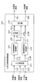
- FIG. 1 is a block diagram showing a configuration of a 3D image display system according to Embodiment 1 of the present invention.
- HDMI High-Definition Multimedia Interface
- the digital video recorder 30 converts the format of a three-dimensional image recorded on an optical disc 41 such as a BD (Blu-ray disc) and outputs the converted three-dimensional image to the digital television 20 via the HDMI cable 40.
- an optical disc 41 such as a BD (Blu-ray disc)
- the digital TV 20 converts the 3D image output from the digital video recorder 30 and the 3D image format included in the broadcast wave 42 and displays the converted image.
- the broadcast wave 42 is a terrestrial digital television broadcast, a satellite digital television broadcast, or the like.
- the digital video recorder 30 may convert the format of a three-dimensional image recorded on a recording medium other than the optical disk 41 (for example, a hard disk drive, a nonvolatile memory, or the like).
- the digital video recorder 30 may convert the format of a 3D image included in the broadcast wave 42 or a 3D image acquired via a communication network such as the Internet.
- the digital video recorder 30 may convert the format of the three-dimensional image input to an external input terminal (not shown) or the like by an external device.
- the digital television 20 may convert the format of the three-dimensional image recorded on the optical disc 41 and other recording media.
- the digital television 20 may convert the format of the 3D image acquired via a communication network such as the Internet.
- the digital television 20 may convert the format of a three-dimensional image input to an external input terminal (not shown) or the like by an external device other than the digital video recorder 30.
- the digital television 20 and the digital video recorder 30 may be connected by a standard cable other than the HDMI cable 40, or may be connected by a wireless communication network.
- the digital video recorder 30 includes an input unit 31, a decoder 32, a 3D image processing apparatus 100B, and an HDMI communication unit 33.
- the input unit 31 acquires the encoded three-dimensional image 51 recorded on the optical disc 41.
- the decoder 32 generates an input 3D image 52 by decoding the encoded 3D image 51 acquired by the input unit 31.
- the 3D image processing apparatus 100B generates an output 3D image 53 by converting the format of the input 3D image 52.
- the HDMI communication unit 33 outputs the output 3D image 53 generated by the 3D image processing apparatus 100 ⁇ / b> B to the digital television 20 via the HDMI cable 40.
- the digital video recorder 30 may store the generated output 3D image 53 in a storage unit (such as a hard disk drive and a non-volatile memory) provided in the digital video recorder 30 or attach / detach to / from the digital video recorder 30. You may record on a possible recording medium (optical disc etc.).
- a storage unit such as a hard disk drive and a non-volatile memory
- the digital television 20 includes an input unit 21, a decoder 22, an HDMI communication unit 23, a 3D image processing apparatus 100, a left screen drive unit 24L, a right screen drive unit 24R, a display panel 26, and a transmitter 27. Is provided.
- the input unit 21 acquires the encoded three-dimensional image 55 included in the broadcast wave 42.
- the decoder 22 generates an input 3D image 56 by decoding the encoded 3D image 55 acquired by the input unit 21.
- the HDMI communication unit 23 acquires the output 3D image 53 output by the HDMI communication unit 33 and outputs it as an input 3D image 57.
- the 3D image processing apparatus 100 generates an output 3D image 58 by converting the format of the input 3D image 56 or the input 3D image 57.
- the output three-dimensional image 58 includes a left screen image 58L and a right screen image 58R.
- the left screen drive unit 24L displays the left screen image 58L on the left screen 26L of the display panel 26.
- the right screen drive unit 24R displays the right screen image 58R on the right screen 26R of the display panel 26.
- the transmitter 27 controls the shutter glasses 43 using wireless communication.
- the format conversion process by the 3D image processing apparatus 100 will be described.
- the format conversion process for the input three-dimensional image 56 by the three-dimensional image processing apparatus 100 will be described as an example.
- the format conversion process for the input three-dimensional image 57 by the three-dimensional image processing apparatus 100 and the third order The format conversion process for the input three-dimensional image 52 by the original image processing apparatus 100B is the same.
- the format refers to the arrangement pattern of the left-eye image and the right-eye image in each frame (field) (hereinafter simply referred to as “arrangement pattern”), the frame rate, and the scanning method (progressive and interlaced). Race) and image size.
- the 3D image processing apparatus 100 generates the output 3D image 58 by converting any one or more of the arrangement pattern, the frame rate, the scanning method, and the image size of the input 3D image 56.
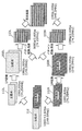
- FIG. 2A and 2B are diagrams illustrating an example of format conversion processing of the 3D image processing apparatus 100.
- FIG. 1 is a diagram illustrating an example of format conversion processing of the 3D image processing apparatus 100.
- the input three-dimensional image 56 includes a left-eye image 56l and a right-eye image 56r in each field.
- the three-dimensional image processing apparatus 100 converts the arrangement pattern of the input three-dimensional image 56, whereby an output in which frames including only the left-eye image 58l and frames including only the right-eye image 58r are alternately arranged.
- a three-dimensional image 58 is generated.
- the 3D image processing apparatus 100 converts the input 3D image 56 of 60i (interlace method with a frame rate of 60 fps) into an output 3D image 58 of 120p (progressive method with a frame rate of 120 fps).
- the shutter glasses 43 are, for example, liquid crystal shutter glasses worn by a viewer, and include a left-eye liquid crystal shutter and a right-eye liquid crystal shutter.
- the transmitter 27 controls the opening and closing of the left-eye liquid crystal shutter and the right-eye liquid crystal shutter in accordance with the display timing of the left-eye image 58l and the right-eye image 58r. Specifically, the transmitter 27 opens the left-eye liquid crystal shutter of the shutter glasses 43 and closes the right-eye liquid crystal shutter during the period in which the left-eye image 58l is displayed. Further, the transmitter 27 closes the left-eye liquid crystal shutter of the shutter glasses 43 and opens the right-eye liquid crystal shutter during the period in which the right-eye image 58r is displayed.
- the left eye image 58l and the right eye image 58r are selectively incident on the viewer's left eye and the right eye, respectively.
- the method of selectively causing the left-eye image 58l and the right-eye image 58r to enter the viewer's left eye and right eye is not limited to this method, and other methods may be used.
- the input three-dimensional image 56 includes a left-eye image 56l and a right-eye image 56r in each field.
- the three-dimensional image processing apparatus 100B converts the arrangement pattern of the input three-dimensional image 52 into an output three-dimensional image 58 in which the left-eye image 58l and the right-eye image 58r are arranged in a checkered pattern in each frame. .
- the display panel 26 includes a left-eye polarizing film formed on the left-eye pixel and a right-eye polarizing film formed on the right-eye pixel.
- Different polarized light linearly polarized light, circularly polarized light, or the like
- the shutter glasses 43 instead of the shutter glasses 43, by using polarized glasses having left-eye and right-eye polarization filters respectively corresponding to the polarized light, the left-eye image 58l and the left-eye and right-eye of the viewer are displayed.
- the right-eye image 58r can be made incident.
- the arrangement pattern of the output three-dimensional image 58 matches the arrangement pattern of the polarizing film.
- arrangement pattern of the input three-dimensional image 56 and the output three-dimensional image 58 may be any one of the following arrangement patterns.
- 3A, 3B, 4A, 4B, 5A, 5B, 6A, and 6B are diagrams showing arrangement patterns of a three-dimensional image.
- the left-eye image 60l and the right-eye image 60r are arranged side by side in the vertical direction in one frame.
- this arrangement pattern is referred to as a frame sequential.
- the left-eye image 60l and the right-eye image 60r are arranged in a horizontal direction in one frame.
- this arrangement pattern is called side-by-side.
- FIGS. 3A and 3B shows an example of a so-called full high-definition image in which one frame is composed of pixels of 1920 columns ⁇ 1080 rows, but the number of pixels included in one frame is other than this number. There may be.
- a so-called high-definition image in which one frame is composed of pixels of 1270 columns ⁇ 720 rows may be used.
- each frame includes a left-eye image 60l and a right-eye image 60r that are each compressed in half in the vertical direction or the horizontal direction, but is not compressed.
- a left-eye image 60l and a right-eye image 60r each including 1920 columns ⁇ 1080 rows may be included.
- it may be compressed at a compression rate other than 1/2, or may be compressed both in the vertical direction and in the horizontal direction.
- the 3D image scanning method may be a progressive method or an interlace method in which a top field and a bottom field are alternately arranged.
- the frame rate of the 3D image may be an arbitrary value.
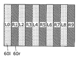
- the left-eye image 60l and the right-eye image 60r are arranged in a checkered pattern.
- this arrangement pattern is referred to as a checker pattern.
- FIG. 4A, FIG. 4B, FIG. 5A, FIG. 5B, FIG. 6A and FIG. 6B only the pixels of 10 columns ⁇ 6 rows are displayed for simplicity of explanation. A number of pixels are arranged.
- the notations such as L0 and R1 shown in FIGS. 4A and 4B indicate the horizontal positions of the pixels of the left-eye image 60l and the right-eye image 60r. That is, the pixel L0 is the pixel in the 0th column of the left eye image 60l, and the pixel R1 is the pixel in the 1st column of the right eye image 60r.
- the left-eye image 60l and the right-eye image 60r may be arranged in a checkered pattern in units of one pixel, or a checkered pattern having a plurality of pixel units, for example, a group of 2 columns ⁇ 2 rows of pixels as one unit. It may be arranged in a shape.
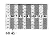
- the left-eye image 60l and the right-eye image 60r are arranged in a vertical stripe shape.
- this arrangement pattern is referred to as vertical interleaving.
- the notations such as L0 and R1 shown in FIGS. 5A and 5B indicate the horizontal positions of the pixels of the left-eye image 60l and the right-eye image 60r. That is, the pixel L0 is the pixel in the 0th column of the left eye image 60l, and the pixel R1 is the pixel in the 1st column of the right eye image 60r.
- left-eye image 60l and the right-eye image 60r may be alternately arranged for each column, or may be alternately arranged for a plurality of columns.
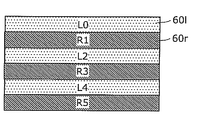
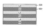
- the left-eye image 60l and the right-eye image 60r are arranged in a horizontal stripe shape.
- this arrangement pattern is referred to as line sequential.
- the notations such as L0 and R1 shown in FIGS. 6A and 6B indicate the positions of the pixels of the left-eye image 60l and the right-eye image 60r in the vertical direction. That is, the pixel L0 is the pixel in the 0th row of the left eye image 60l, and the pixel R1 is the pixel in the 1st row of the right eye image 60r.
- left-eye image 60l and the right-eye image 60r may be alternately arranged for each row, or may be alternately arranged for every plurality of rows.
- the left eye image and the right eye image may be arranged in reverse.
- FIG. 7 is a diagram illustrating an example of the left-eye image 58l and the right-eye image 58r.
- the objects included in the left-eye image 58l and the right-eye image 58r have parallax according to the distance of the object from the shooting position.
- the 3D image processing apparatus 100B included in the digital video recorder 30 when the format conversion is performed, for example, the 3D image processing apparatus 100B changes the arrangement pattern of the input 3D image 52 as shown in FIG. 2B.
- the data is converted into a predetermined arrangement pattern (for example, a checker pattern) and converted into 120p.
- the three-dimensional image processing apparatus 100 included in the digital television 20 converts the arrangement pattern of the 120p input three-dimensional image 57 (for example, the left-eye image 58l and the right-eye image 58r are alternately arranged. Only conversion).
- the 3D image processing apparatus 100B performs the format conversion shown in FIG. 2A, and the 3D image processing apparatus 100 may not perform the format conversion.
- the 3D image processing apparatus 100B may perform a part of the conversion of the arrangement pattern, the frame rate, the scanning method, and the image size, and the 3D image processing apparatus 100 may perform conversions other than the part. .
- a part of process of the three-dimensional image processing apparatus 100 and the three-dimensional image processing apparatus 100B may overlap.
- the three-dimensional image processing apparatus 100 is a composite image including two main screen images (corresponding to the first image of the present invention) and sub-screen images (corresponding to the second image of the present invention) as two two-dimensional images in one screen. And the three-dimensional image processing mode for converting the input three-dimensional image 56 or 57 in the first format into the output three-dimensional image 58 in the second format as described above.
- FIG. 8 is a diagram illustrating an operation example in the two-screen processing mode by the three-dimensional image processing apparatus 100.
- the 3D image processing apparatus 100 in the two-screen processing mode, the 3D image processing apparatus 100 generates a composite image in which reduced sub-screens are arranged on the main screen. Details of the operation in the two-screen processing mode will be described later.
- FIG. 9 is a block diagram showing a configuration of the 3D image processing apparatus 100.
- the 3D image processing apparatus 100 includes an input selection unit 101, a main screen image processing unit 102, a sub screen image processing unit 103, a combining unit 104, and an output unit 105.
- the input selection unit 101 outputs the main screen image 110 to the main screen image processing unit 102 and outputs the sub screen image 111 to the sub screen image processing unit 103 in the two-screen processing mode.
- the input selection unit 101 converts the 3D image 112 into the left screen input image 112L (corresponding to the first input image of the present invention) and the right screen input image 112R (second input image of the present invention).
- the left screen input image 112L is output to the main screen image processing unit 102
- the right screen input image 112R is output to the sub screen image processing unit 103.
- the input selection unit 101 outputs the 3D image 112 to the main screen image processing unit 102 and the sub screen image processing unit 103, respectively, and the main screen image processing unit 102 outputs the 3D image 112 from the 3D image 112.
- the left screen input image 112L may be extracted, and the sub screen image processing unit 103 may extract the right screen input image 112R from the three-dimensional image 112.
- the main screen image 110 and the sub screen image 111 are different two-dimensional images.
- the main screen image 110 and the sub screen image 111 are an image of the first channel included in the broadcast wave 42, an image of the second channel included in the broadcast wave 42, and an image acquired by the HDMI communication unit 23. Two of them are images.
- the three-dimensional image 112 is the input three-dimensional image 56 or 57 described above.
- the left screen input image 112L is an image of the left half of the 3D image 112
- the right screen input image 112R is an image of the right half of the 3D image 112.
- the main screen image processing unit 102 converts the format of the main screen image 110 output by the input selection unit 101 to thereby convert the main screen processed image 150. (Corresponding to the first processed image of the present invention) is generated.
- the main screen image processing unit 102 converts the format of the left screen input image 112L output by the input selection unit 101, thereby converting the left screen output image 153L (first output image of the present invention). Equivalent).
- the sub-screen image processing unit 103 converts the format of the sub-screen image 111 output by the input selection unit 101, thereby sub-screen processing image 151. (Corresponding to the second processed image of the present invention) is generated. Further, in the 3D image processing mode, the sub-screen image processing unit 103 converts the format of the right screen input image 112R output by the input selection unit 101, thereby converting the right screen output image 153R (second output image of the present invention). Equivalent).
- the combining unit 104 generates a composite image 152 by combining the main screen processed image 150 generated by the main screen image processing unit 102 and the sub screen processed image 151 generated by the sub screen image processing unit 103. .
- the output unit 105 divides the composite image 152 generated by the combining unit 104 into a left screen image 58L and a right screen image 58R in the two-screen processing mode.
- the output unit 105 outputs the divided left screen image 58L to the left screen drive unit 24L, and outputs the divided right screen image 58R to the right screen drive unit 24R.
- the output unit 105 outputs the left screen output image 153L generated by the main screen image processing unit 102 as the left screen image 58L to the left screen driving unit 24L, and the sub screen image processing unit 103.
- the right screen output image 153R generated by the above is output as the right screen image 58R to the right screen drive unit 24R.
- FIG. 10 is a block diagram showing the configuration of the main screen image processing unit 102 and the sub screen image processing unit 103.
- the main screen image processing unit 102 includes a main screen preprocessing unit 120 and a main screen postprocessing unit 121.
- the 3D image processing apparatus 100 further includes a memory 140 and a memory controller 141.
- the main screen pre-processing unit 120 (corresponding to the first pre-processing unit of the present invention) reduces the image size of the main screen image 110 or the left screen input image 112L and converts the scanning method, thereby converting the left screen processed image. 160L (corresponding to the third processed image of the present invention) is generated.
- the main screen preprocessing unit 120 includes a horizontal reduction unit 122, an IP conversion unit 123, and a vertical reduction unit 124.
- the horizontal reduction unit 122 reduces and outputs the horizontal image size of the main screen image 110 or the left screen input image 112L.
- the IP conversion unit 123 converts the scanning method of the image output from the horizontal reduction unit 122 from the interlace method to the progressive method (hereinafter referred to as “IP conversion”), and outputs the converted image.
- IP conversion is a process of interpolating pixels in a nonexistent row in an interlaced image.
- pixels in a non-existing row are interpolated using pixels around the same field, or the same or surrounding pixels in a field having a different field determination signal immediately or immediately after.
- which pixel is used for interpolation is determined according to the motion of the image.
- the field determination signal is a signal indicating whether the field is a top field or a bottom field.
- the vertical reduction unit 124 generates and outputs a left screen processed image 160L by reducing the image size in the vertical direction of the image output by the IP conversion unit 123.
- a method for reducing the image size a method of thinning out pixels or a method of calculating an average value of a plurality of pixels can be used.
- the order of processing by the horizontal reduction unit 122, the IP conversion unit 123, and the vertical reduction unit 124 illustrated in FIG. 10 is an example, and the processing by each processing unit may be performed in an arbitrary order.
- the memory controller 141 writes and reads 149 data to and from the memory.
- the main screen preprocessing unit 120 stores the generated left screen processed image 160L in the memory 140 via the memory controller 141.
- the main screen post-processing unit 121 (corresponding to the first post-processing unit of the present invention) includes at least one of the left screen processed image 160L and the right screen processed image 160R stored in the memory 140 via the memory controller 141.
- the left screen processed image 161L (corresponding to the fifth processed image of the present invention) is read.
- the left screen processed image 161L includes pixels corresponding to the left screen 26L of the display panel 26 among the pixels included in the left screen processed image 160L and the right screen processed image 160R stored in the memory 140. .
- the main screen post-processing unit 121 generates the main screen processed image 150 or the left screen output image 153L by enlarging the image size of the left screen processed image 161L and converting the arrangement pattern and the frame rate.
- the main screen post-processing unit 121 includes a pattern conversion unit 125, a vertical enlargement unit 126, and a horizontal enlargement unit 127.
- the pattern conversion unit 125 converts the arrangement pattern and frame rate of the left screen processed image 161L and outputs the result.
- the pattern conversion unit 125 may convert the arrangement pattern and the frame rate after reading the left screen processed image 161L, or read the pixels by reading out the left screen processed image 161L in the arrangement order. At the same time, pattern conversion and frame rate conversion may be performed.
- the vertical enlargement unit 126 enlarges and outputs the image size in the vertical direction of the image output by the pattern conversion unit 125.
- the horizontal enlargement unit 127 enlarges and outputs the image size in the horizontal direction of the image output by the vertical enlargement unit 126.
- a method for enlarging the image size a method of simply copying pixels or a method of interpolating nonexistent pixels can be used.
- the order of processing by the pattern conversion unit 125, the vertical enlargement unit 126, and the horizontal enlargement unit 127 illustrated in FIG. 10 is an example, and the processing by each processing unit may be performed in an arbitrary order.
- the configuration of the sub-screen image processing unit 103 will be described. Note that the configuration of the sub-screen image processing unit 103 is the same as that of the main screen image processing unit 102.
- the sub-screen image processing unit 103 includes a sub-screen pre-processing unit 130 and a sub-screen post-processing unit 131.
- the sub-screen pre-processing unit 130 (corresponding to the second pre-processing unit of the present invention) reduces the image size of the sub-screen image 111 or the right screen input image 112R and performs IP conversion so that the right screen processed image 160R ( Corresponding to the fourth processed image of the present invention).
- the sub-screen preprocessing unit 130 includes a horizontal reduction unit 132, an IP conversion unit 133, and a vertical reduction unit 134.
- the horizontal reduction unit 132 reduces and outputs the horizontal image size of the sub-screen image 111 or the right screen input image 112R.
- the IP conversion unit 133 performs IP conversion on the image output by the horizontal reduction unit 132 and outputs it.
- the vertical reduction unit 134 generates and outputs the right screen processed image 160R by reducing the image size in the vertical direction of the image output by the IP conversion unit 133.
- the order of processing by the horizontal reduction unit 132, the IP conversion unit 133, and the vertical reduction unit 134 illustrated in FIG. 10 is an example, and the processing by each processing unit may be performed in an arbitrary order.
- the sub-screen preprocessing unit 130 stores the generated right screen processed image 160R in the memory 140 via the memory controller 141.
- the sub-screen post-processing unit 131 (corresponding to the second post-processing unit of the present invention) includes at least one of the left screen processed image 160L and the right screen processed image 160R stored in the memory 140 via the memory controller 141.
- the right screen processed image 161R (corresponding to the sixth processed image of the present invention) is read.
- the right screen processed image 161R is the right screen output image 153R (the right screen 26R of the display panel 26) among the pixels included in the left screen processed image 160L and the right screen processed image 160R stored in the memory 140. ).
- the sub-screen post-processing unit 131 generates the sub-screen processed image 151 or the right screen output image 153R by increasing the image size of the right screen processed image 160R and converting the arrangement pattern and the frame rate.
- the sub-screen post-processing unit 131 includes a pattern conversion unit 135, a vertical enlargement unit 136, and a horizontal enlargement unit 137.
- the pattern conversion unit 135 converts and outputs the arrangement pattern and frame rate of the right screen processed image 161R.
- the pattern conversion unit 135 may convert the arrangement pattern and the frame rate after reading out the right screen processed image 161R, or read out the pixels by reading out the right screen processed image 161R in the arrangement order. At the same time, pattern conversion and frame rate conversion may be performed.
- the vertical enlargement unit 136 enlarges and outputs the image size in the vertical direction of the image output by the pattern conversion unit 135.
- the horizontal enlargement unit 137 enlarges and outputs the image size in the horizontal direction of the image output by the vertical enlargement unit 136.
- the order of processing by the pattern conversion unit 135, the vertical enlargement unit 136, and the horizontal enlargement unit 137 shown in FIG. 10 is an example, and the processing by each processing unit may be performed in an arbitrary order.
- the main screen image 110 and the sub screen image 111 are 480i and the frame rate is 60 fps.
- the input selection unit 101 outputs the main screen image 110 to the main screen image processing unit 102 and outputs the sub screen image 111 to the sub screen image processing unit 103.
- the main screen image processing unit 102 performs IP conversion of the main screen image 110 and expands the image size from high definition to full high definition, thereby generating a main screen processed image 150 of 1080p and 60 fps.
- the IP conversion unit 123 generates a converted image of 720p and 60 fps by performing IP conversion on the main screen image 110.
- the vertical enlargement unit 126 and the horizontal enlargement unit 127 generate the 1080p and 60 fps main screen processed image 150 by enlarging the converted image.
- the sub-screen image processing unit 103 converts the scanning method of the sub-screen image 111 from the interlace method to the progressive method and reduces the image size to generate, for example, a sub-screen processed image 151 of 400 p and 60 fps. To do.
- the horizontal reduction unit 132 reduces the horizontal image size of the sub-screen image 111
- the IP conversion unit 133 converts the reduced image scanning method from the interlace method to the progressive method.
- 720p and 60 fps converted images are generated.
- the vertical reduction unit 134 generates a 400p and 60 fps sub-screen processed image 151 by reducing the vertical image size of the converted image.
- the synthesizing unit 104 synthesizes the main screen processed image 150 generated by the main screen image processing unit 102 and the sub-screen processed image 151 generated by the sub-screen image processing unit 103, thereby 1080p and 60fps.
- the composite image 152 is generated.
- the output unit 105 divides the combined image 152 generated by the combining unit 104 into a left screen image 58L and a right screen image 58R.
- the output unit 105 outputs the divided left screen image 58L to the left screen drive unit 24L, and outputs the divided right screen image 58R to the right screen drive unit 24R.
- the 3D image processing apparatus 100 can generate a composite image in which a reduced sub-screen is displayed on the main screen.
- the main screen image processing unit 102 performs image size reduction processing. Is called.
- the main screen image processing unit 102 performs image size reduction processing.
- the 3D image processing apparatus 100 generates a composite image in which the main screen and the sub screen are arranged on the divided sub screen instead of generating a composite image in which the sub screen is superimposed on the main screen.
- a mode for generating a composite image in which the sub screen is superimposed on the main screen and a mode for generating a composite image in which the main screen and the sub screen are arranged on the divided sub screen.
- the main screen preprocessing unit 120 once reduces the image size of the main screen image 110, and then the main screen postprocessing unit 121.
- the image size may be increased so that the reduced image size is restored to the original image size.
- the main screen preprocessing unit 120 sets the image size of the main screen image 110. May be reduced to 1 ⁇ 2 in the vertical direction, and the main screen post-processing unit 121 may enlarge the reduced image size twice in the vertical direction.
- the amount of data stored in the memory 140 can be reduced, the capacity of the memory 140 can be reduced. Furthermore, the amount of processing in the IP conversion unit 123, the pattern conversion unit 125, and the like can be reduced.
- the sub-screen pre-processing unit 130 once sets the sub-screen image 111 and the display image size of the display panel 26 regardless of the image size.
- the sub-screen post-processing unit 131 may enlarge the image size so that the reduced image size is restored to the original image size.
- main screen image processing unit 102 and the sub screen image processing unit 103 may perform processing for increasing or decreasing the frame rate.
- the 3D image processing apparatus 100 has a normal mode in which only one normal image is displayed on one screen in addition to the two-screen processing mode and the three-dimensional image processing mode.
- the main screen image processing unit 102 performs format conversion of the one image.
- FIG. 11 to FIG. 16 are diagrams showing an operation example in the 3D image processing mode by the 3D image processing apparatus 100.
- the three-dimensional image 112 is a full-size 1080i frame sequential and 60 fps image. That is, the three-dimensional image 112 includes a left eye image 60l of 1080i (1920 columns ⁇ 540 rows) and a right eye image 60r of 1080i (1920 columns ⁇ 540 rows) in one field.
- the dot clock of the three-dimensional image 112 is 148.5 MHz.
- the dot clock is a value represented by the product of the image size (number of rows ⁇ number of columns) and the frame rate. That is, the higher the dot clock, the shorter the time that can be used for processing one pixel, in other words, the larger the amount of data to be processed per unit time.
- the display panel 26 displays 1080p and 120 fps images in which the left-eye images 60l and the right-eye images 60r are alternately arranged.
- the input selection unit 101 divides the three-dimensional image 112 into a left screen input image 112L and a right screen input image 112R, and outputs the left screen input image 112L to the main screen image processing unit 102.
- the input image 112R is output to the sub-screen image processing unit 103.
- the left screen input image 112L and the right screen input image 112R are half the image size of the three-dimensional image 112. Therefore, the dot clock of the left screen input image 112L and the right screen input image 112R is 74.25 MHz which is half of the dot clock of the three-dimensional image 112.
- the left screen input image 112L includes a left eye image 60l of 1080i / 2 (960 columns ⁇ 540 rows) and a right eye image 60r of 1080i / 2 (960 columns ⁇ 540 rows) in one field.
- the right screen input image 112R includes a left eye image 60l of 1080i / 2 (960 columns ⁇ 540 rows) and a right eye image 60r of 1080i / 2 (960 columns ⁇ 540 rows) in one field.
- the image sizes of the left screen input image 112L and the right screen input image 112R are 960 columns ⁇ 1080 rows, respectively.
- the main screen preprocessing unit 120 performs I / P conversion on the left screen input image 112L to generate a left screen processed image 160L of 1080p and 60 fps.
- This I / P conversion doubles the vertical image size. Therefore, the dot clock of the left screen processed image 160L is 148.5 MHz, which is twice that of the left screen input image 112L.
- the left screen processed image 160L includes a left-eye image 60l of 1080p / 2 (960 columns ⁇ 1080 rows) and a right-eye image 60r of 1080p / 2 (960 columns ⁇ 1080 rows) per frame. including. Therefore, the image size of the left screen processed image 160L is 960 columns ⁇ 2160L rows.
- the main screen preprocessing unit 120 stores the left screen processed image 160L in the memory 140 via the memory controller 141.
- the main screen post-processing unit 121 reads the left screen processed image 160L via the memory controller 141.
- the main screen post-processing unit 121 performs 1080p / 2 (960) in which the left-eye image 60l and the right-eye image 60r are alternately arranged by performing pattern conversion and double speeding of the left-screen processed image 160L.
- Column x 1080 rows) and 120 fps left screen output image 153L is generated.
- the dot clock of the left screen output image 153L is 148.5 MHz, which is the same as the dot clock of the left screen processed image 160L.
- the sub screen image processing unit 103 performs the same processing as the main screen image processing unit 102 on the right screen input image 112R.
- the sub-screen preprocessing unit 130 performs I / P conversion on the right screen input image 112R to generate a 1080p and 60 fps right screen processed image 160R.
- This I / P conversion doubles the vertical image size. Therefore, the dot clock of the right screen processed image 160R is 148.5 MHz, which is twice that of the right screen input image 112R.
- the right screen processed image 160R includes a left-eye image 60l of 1080p / 2 (960 columns ⁇ 1080 rows) and a right-eye image 60r of 1080p / 2 (960 columns ⁇ 1080 rows) per frame. including. Therefore, the image size of the right screen processed image 160R is 960 columns ⁇ 2160 L rows.
- the sub-screen preprocessing unit 130 stores the right screen processed image 160R in the memory 140 via the memory controller 141.
- the sub-screen post-processing unit 131 reads the right-screen processed image 160R via the memory controller 141.
- the sub-screen post-processing unit 131 performs 1080p / 2 (960) in which the left-eye image 60l and the right-eye image 60r are alternately arranged by performing pattern conversion and double speeding of the right-screen processed image 160R.
- the dot clock of the right screen output image 153R is 148.5 MHz, which is the same as the dot clock of the right screen processed image 160R.
- the output unit 105 outputs the left screen output image 153L generated by the main screen image processing unit 102 to the left screen drive unit 24L as the left screen image 58L, and the right screen generated by the sub screen image processing unit 103.
- the output image 153R is output to the right screen drive unit 24R as the right screen image 58R.
- the left screen drive unit 24L displays the left screen image 58L on the left screen 26L of the display panel 26.
- the right screen drive unit 24R displays the right screen image 58R on the right screen 26R of the display panel 26.
- the main screen image processing unit 102 and the sub screen image processing unit 103 each process an image with a maximum dot clock of 148 and 5 MHz.
- an image with a dot clock of 297 MHz can be generated.
- the three-dimensional image 112 is a full-size 720p frame sequential and 60 fps image. That is, the 3D image 112 includes a left-eye image 60l of 720p (1270 columns ⁇ 720 rows) and a right-eye image 60r of 720p (1270 columns ⁇ 720 rows) in one frame. That is, the dot clock of the three-dimensional image 112 is 148.5 MHz.
- the display panel 26 displays 1080p and 120 fps images in which the left-eye images 60l and the right-eye images 60r are alternately arranged.
- the input selection unit 101 divides the three-dimensional image 112 into a left screen input image 112L and a right screen input image 112R, and outputs the left screen input image 112L to the main screen image processing unit 102.
- the input image 112R is output to the sub-screen image processing unit 103.
- the left screen input image 112L and the right screen input image 112R are half the image size of the three-dimensional image 112. Therefore, the dot clock of the left screen input image 112L and the right screen input image 112R is 74.25 MHz which is half of the dot clock of the three-dimensional image 112.
- the left screen input image 112L includes a left-eye image 60l of 720p / 2 (635 columns ⁇ 720 rows) and a right-eye image 60r of 720p / 2 (635 columns ⁇ 720 rows) per frame.
- the right screen input image 112R includes a left-eye image 60l of 720p / 2 (635 columns ⁇ 720 rows) and a right-eye image 60r of 720p / 2 (635 columns ⁇ 720 rows) in one frame.
- the image sizes of the left screen input image 112L and the right screen input image 112R are 635 columns ⁇ 1440 rows, respectively.
- the main screen preprocessing unit 120 stores the left screen input image 112L (left screen processed image 160L) in the memory 140 via the memory controller 141.
- the main screen post-processing unit 121 reads the left screen processed image 160L via the memory controller 141. At this time, the main screen post-processing unit 121 performs pattern conversion and double speeding of the left screen processed image 160L, so that the left eye image 60l and the right eye image 60r are alternately arranged 720p / 2 (635 Column 720 rows) and 120 fps left screen processed image 163L is generated.
- the dot clock of the left screen processed image 163L is 74.25 MHz, which is the same as the dot clock of the left screen processed image 160L.
- the main screen post-processing unit 121 enlarges the image size of the left screen processed image 163L to thereby arrange 1080p / 2 (960 rows ⁇ 960 images) in which the left eye image 60l and the right eye image 60r are alternately arranged. 1080 line) and 120 fps left screen output image 153L.
- This enlargement process doubles the image size. Therefore, the dot clock of the left screen output image 153L is 148.5 MHz, which is twice the dot clock of the left screen processed image 163L.
- the sub-screen image processing unit 103 performs pattern conversion and double speed conversion of the right screen processed image 160R so that the left-eye image 60l and the right-eye image 60r alternate.
- 720p / 2 (635 columns ⁇ 720 rows) and 120 fps right screen processed image 163R are generated.
- the sub-screen post-processing unit 131 generates a right screen output image 153R of 1080p / 2 (960 columns ⁇ 1080 rows) and 120 fps by enlarging the image size of the right screen processed image 163R.
- the output unit 105 outputs the left screen output image 153L generated by the main screen image processing unit 102 to the left screen drive unit 24L as the left screen image 58L, and the right screen generated by the sub screen image processing unit 103.
- the output image 153R is output to the right screen drive unit 24R as the right screen image 58R.
- the left screen drive unit 24L displays the left screen image 58L on the left screen 26L of the display panel 26.
- the right screen drive unit 24R displays the right screen image 58R on the right screen 26R of the display panel 26.
- the main screen post-processing unit 121 cannot generate the left screen output image 153L from only the left screen processed image 160L generated by the main screen pre-processing unit 120. Therefore, the main screen post-processing unit 121 uses the left screen processed image 160L generated by the main screen pre-processing unit 120 and the right screen processed image 160R generated by the sub-screen pre-processing unit 130 to output the left screen. An image 153L is generated.
- the sub-screen post-processing unit 131 cannot generate the right-screen output image 153R only from the right-screen processed image 160R generated by the sub-screen pre-processing unit 130. Therefore, the sub-screen post-processing unit 131 uses the left-screen processed image 160L generated by the main-screen pre-processing unit 120 and the right-screen processed image 160R generated by the sub-screen pre-processing unit 130 to output the right screen. An image 153R is generated.
- the three-dimensional image 112 is a full-size 1080i side-by-side and 60 fps image. That is, the three-dimensional image 112 includes a left eye image 60l of 1080i (1920 columns ⁇ 540 rows) and a right eye image 60r of 1080i (1920 columns ⁇ 540 rows) in one field. That is, the dot clock of the three-dimensional image 112 is 148.5 MHz.
- the display panel 26 displays 1080p and 120 fps images in which the left-eye images 60l and the right-eye images 60r are alternately arranged.
- the input selection unit 101 divides the three-dimensional image 112 into a left screen input image 112L and a right screen input image 112R, and outputs the left screen input image 112L to the main screen image processing unit 102.
- the input image 112R is output to the sub-screen image processing unit 103.
- the left screen input image 112L and the right screen input image 112R are half the image size of the three-dimensional image 112. Therefore, the dot clock of the left screen input image 112L and the right screen input image 112R is 74.25 MHz which is half of the dot clock of the three-dimensional image 112.
- the left screen input image 112L includes a left-eye image 60l of 1080i (1920 columns ⁇ 540 rows) in one field.
- the right screen input image 112R includes a 1080i (1920 columns ⁇ 540 rows) right-eye image 60r in one field. That is, the image sizes of the left screen input image 112L and the right screen input image 112R are 1920 columns ⁇ 540 rows, respectively.
- the main screen preprocessing unit 120 performs I / P conversion on the left screen input image 112L to generate a left screen processed image 160L of 1080p and 60 fps.
- This I / P conversion doubles the vertical image size. Therefore, the dot clock of the left screen processed image 160L is 148.5 MHz, which is twice that of the left screen input image 112L.
- the left screen processed image 160L includes a left-eye image 60l of 1080p (1920 columns ⁇ 1080 rows) in one frame. Therefore, the image size of the left screen processed image 160L is 1920 columns ⁇ 1080 rows.
- the main screen preprocessing unit 120 stores the left screen processed image 160L in the memory 140 via the memory controller 141.
- the sub-screen pre-processing unit 130 generates a 1080p and 60 fps right-screen processed image 160R by performing I / P conversion on the right-screen input image 112R.
- This I / P conversion doubles the vertical image size. Therefore, the dot clock of the right screen processed image 160R is 148.5 MHz, which is twice that of the right screen input image 112R.
- the right screen processed image 160R includes a right-eye image 60r of 1080p (1920 columns ⁇ 1080 rows) in one frame. Therefore, the image size of the right screen processed image 160R is 1920 columns ⁇ 1080 rows.
- the sub-screen preprocessing unit 130 stores the right screen processed image 160R in the memory 140 via the memory controller 141.
- the main screen post-processing unit 121 via the memory controller 141, among the plurality of pixels included in the left screen processed image 160L and the right screen processed image 160R, a plurality of pixels corresponding to the left screen 26L of the display panel 26.
- a left screen processed image 161L including pixels is read out.
- the main screen post-processing unit 121 performs 1080p / 2 (960 columns) in which the left-eye image 60l and the right-eye image 60r are alternately arranged by performing pattern conversion and double speeding of the left-screen processed image 161L. ⁇ 1080 lines) and a left screen output image 153L of 120 fps is generated.
- the main screen post-processing unit 121 reads the left half of the left screen processed image 160L and the left half of the right screen processed image 160R, and also reads the left half of the read left screen processed image 160L and the right screen processed image 160R.
- the left screen output image 153L is generated by alternately arranging the left half of the left screen.
- the dot clock of the left screen output image 153L is 148.5 MHz, which is the same as the dot clock of the left screen processed image 160L.
- the sub-screen post-processing unit 131 is connected to the display panel 26 among a plurality of pixels included in the left screen processed image 160L and the right screen processed image 160R via the memory controller 141.
- a right screen processed image 161R including a plurality of pixels corresponding to the right screen 26R is read out.
- the sub-screen post-processing unit 131 performs 1080p / 2 (960 columns) in which the left-eye image 60l and the right-eye image 60r are alternately arranged by performing pattern conversion and double speeding of the right-screen processed image 161R.
- X 1080 lines) and 120 fps right screen output image 153R is generated.
- the sub-screen post-processing unit 131 reads the right half of the left screen processed image 160L and the right half of the right screen processed image 160R, and the right half of the read left screen processed image 160L and the right screen processed image 160R.
- the right screen output image 153R is generated by alternately arranging the right half of the right screen.
- the dot clock of the right screen output image 153R is 148.5 MHz, which is the same as the dot clock of the left screen processed image 160L.
- the output unit 105 outputs the left screen output image 153L generated by the main screen image processing unit 102 to the left screen drive unit 24L as the left screen image 58L, and the right screen generated by the sub screen image processing unit 103.
- the output image 153R is output to the right screen drive unit 24R as the right screen image 58R.
- the left screen drive unit 24L displays the left screen image 58L on the left screen 26L of the display panel 26.
- the right screen drive unit 24R displays the right screen image 58R on the right screen 26R of the display panel 26.
- the three-dimensional image 112 is a full-size 720p side-by-side and 60 fps image. That is, the 3D image 112 includes a left-eye image 60l of 720p (1270 columns ⁇ 720 rows) and a right-eye image 60r of 720p (1270 columns ⁇ 720 rows) in one frame. That is, the dot clock of the three-dimensional image 112 is 148.5 MHz.
- the display panel 26 displays 1080p and 120 fps images in which the left-eye images 60l and the right-eye images 60r are alternately arranged.
- the input selection unit 101 divides the three-dimensional image 112 into a left screen input image 112L and a right screen input image 112R, and outputs the left screen input image 112L to the main screen image processing unit 102.
- the input image 112R is output to the sub-screen image processing unit 103.
- the left screen input image 112L and the right screen input image 112R are half the image size of the three-dimensional image 112. Therefore, the dot clock of the left screen input image 112L and the right screen input image 112R is 74.25 MHz which is half of the dot clock of the three-dimensional image 112.
- the left screen input image 112L includes a left-eye image 60l of 720p (1270 columns ⁇ 720 rows) in one frame.
- the right screen input image 112R includes a right-eye image 60r of 720p (1270 columns ⁇ 720 rows) in one frame. That is, the image sizes of the left screen input image 112L and the right screen input image 112R are 1270 columns ⁇ 720 rows, respectively.
- the main screen preprocessing unit 120 stores the left screen input image 112L (left screen processed image 160L) in the memory 140 via the memory controller 141.
- the sub-screen pre-processing unit 130 stores the right screen input image 112R (right screen processed image 160R) in the memory 140 via the memory controller 141.
- the main screen post-processing unit 121 via the memory controller 141, among the plurality of pixels included in the left screen processed image 160L and the right screen processed image 160R, a plurality of pixels corresponding to the left screen 26L of the display panel 26.
- a left screen processed image 161L including pixels is read out.
- the main screen post-processing unit 121 performs pattern conversion and double speed conversion of the left screen processed image 161L, thereby 720p / 2 (635 columns) in which the left eye image 60l and the right eye image 60r are alternately arranged. ⁇ 720 lines) and 120 fps left screen processed image 163L is generated.
- the main screen post-processing unit 121 reads the left half of the left screen processed image 160L and the left half of the right screen processed image 160R, and also reads the left half of the read left screen processed image 160L and the right screen processed image 160R.
- the left screen output image 153L is generated by alternately arranging the left half of the left screen.
- the dot clock of the left screen processed image 163L is 74.25 MHz, which is the same as the dot clock of the left screen processed image 160L.
- the main screen post-processing unit 121 enlarges the image size of the left screen processed image 163L to thereby arrange 1080p / 2 (960 rows ⁇ 960 images) in which the left eye image 60l and the right eye image 60r are alternately arranged. 1080 line) and 120 fps left screen output image 153L.
- This enlargement process doubles the image size. Therefore, the dot clock of the left screen output image 153L is 148.5 MHz, which is twice the dot clock of the left screen processed image 163L.
- the sub-screen post-processing unit 131 performs the same processing as the main-screen post-processing unit 121, whereby 1080p / 2 (960 rows ⁇ 960) in which the left-eye image 60l and the right-eye image 60r are alternately arranged. 1080 line) and 120 fps right screen output image 153R.
- the output unit 105 outputs the left screen output image 153L generated by the main screen image processing unit 102 to the left screen drive unit 24L as the left screen image 58L, and the right screen generated by the sub screen image processing unit 103.
- the output image 153R is output to the right screen drive unit 24R as the right screen image 58R.
- the left screen drive unit 24L displays the left screen image 58L on the left screen 26L of the display panel 26.
- the right screen drive unit 24R displays the right screen image 58R on the right screen 26R of the display panel 26.
- the three-dimensional image 112 is a 1080i frame sequential and 120 fps image. That is, the three-dimensional image 112 includes a left eye image 60l of 1080i (1920 columns ⁇ 540 rows) and a right eye image 60r of 1080i (1920 columns ⁇ 540 rows) in one field. That is, the dot clock of the three-dimensional image 112 is 148.5 MHz.
- the display panel 26 displays 1080p and 120 fps images in which the left-eye images 60l and the right-eye images 60r are alternately arranged.
- the input selection unit 101 divides the three-dimensional image 112 into a left screen input image 112L and a right screen input image 112R, and outputs the left screen input image 112L to the main screen image processing unit 102.
- the input image 112R is output to the sub-screen image processing unit 103.
- the left screen input image 112L and the right screen input image 112R are half the image size of the three-dimensional image 112. Therefore, the dot clock of the left screen input image 112L and the right screen input image 112R is 74.25 MHz which is half of the dot clock of the three-dimensional image 112.
- the left screen input image 112L includes a left eye image 60l of 1080i / 2 (960 columns ⁇ 540 rows) and a right eye image 60r of 1080i / 2 (960 columns ⁇ 540 rows) in one field.
- the right screen input image 112R includes a left eye image 60l of 1080i / 2 (960 columns ⁇ 540 rows) and a right eye image 60r of 1080i / 2 (960 columns ⁇ 540 rows) in one field.
- the image sizes of the left screen input image 112L and the right screen input image 112R are 480 columns ⁇ 1080 rows, respectively.
- the main screen preprocessing unit 120 performs I / P conversion on the left screen input image 112L to generate a left screen processed image 160L of 1080p / 2 and 120 fps.
- This I / P conversion doubles the vertical image size. Therefore, the dot clock of the left screen processed image 160L is 148.5 MHz, which is twice that of the left screen input image 112L.
- the left screen processed image 160L includes a left-eye image 60l of 1080p / 2 (960 columns ⁇ 1080 rows) and a right-eye image 60r of 1080p / 2 (960 columns ⁇ 1080 rows) per frame. including. Therefore, the image size of the left screen processed image 160L is 960 columns ⁇ 2160L rows.
- the main screen preprocessing unit 120 stores the left screen processed image 160L in the memory 140 via the memory controller 141.
- the main screen post-processing unit 121 reads the left screen processed image 160L via the memory controller 141. At this time, the main screen post-processing unit 121 performs 1080p / 2 (960 columns ⁇ 1080) in which the left-eye image 60l and the right-eye image 60r are alternately arranged by performing pattern conversion of the left-screen processed image 160L. Row) and a left screen processed image 163L of 120 fps is generated. For example, the main screen post-processing unit 121 generates a left screen processed image 163L that alternately includes only one of the left eye image 60l and the right eye image 60r included in each frame of the left screen processed image 160L.
- the dot clock of the left screen output image 153L is 74.25 MHz which is half of the dot clock of the left screen processed image 160L.
- the main screen post-processing unit 121 enlarges the image size of the left screen processed image 163L to thereby arrange 1080p / 2 (960 rows ⁇ 960 images) in which the left eye image 60l and the right eye image 60r are alternately arranged. 1080 line) and 120 fps left screen output image 153L.
- This enlargement process doubles the image size. Therefore, the dot clock of the left screen output image 153L is 148.5 MHz, which is twice the dot clock of the left screen processed image 163L.
- the sub-screen image processing unit 103 performs the same processing as the main screen image processing unit 102 on the right screen input image 112R, thereby alternately arranging the left-eye image 60l and the right-eye image 60r.
- the left screen output image 153L of 1080p / 2 (960 columns ⁇ 1080 rows) and 120 fps is generated.
- the output unit 105 outputs the left screen output image 153L generated by the main screen image processing unit 102 to the left screen drive unit 24L as the left screen image 58L, and the right screen generated by the sub screen image processing unit 103.
- the output image 153R is output to the right screen drive unit 24R as the right screen image 58R.
- the left screen drive unit 24L displays the left screen image 58L on the left screen 26L of the display panel 26.
- the right screen drive unit 24R displays the right screen image 58R on the right screen 26R of the display panel 26.
- the main screen image processing unit 102 and the sub screen image processing unit 103 each process an image with a maximum dot clock of 148 and 5 MHz.
- an image with a dot clock of 297 MHz can be generated.
- the three-dimensional image 112 is a full-size 1080i side-by-side and 60 fps image as in the example shown in FIG.
- the display panel 26 displays line sequential 1080p and 60 fps images.
- the main screen post-processing unit 121 includes a plurality of pixels corresponding to the left screen 26L of the display panel 26 among the plurality of pixels included in the left screen processed image 160L and the right screen processed image 160R via the memory controller 141.
- a left screen processed image 161L including pixels is read out.
- the main screen post-processing unit 121 performs 1080p / 2 (960 columns ⁇ 1080 rows) in which the left-eye image 60l and the right-eye image 60r are alternately arranged by performing pattern conversion of the left-screen processed image 161L. ) And a left screen output image 153L of 60 fps is generated.
- the main screen post-processing unit 121 reads the left half of the left screen processed image 160L and the left half of the right screen processed image 160R, and also reads the left half of the read left screen processed image 160L and the right screen processed image 160R.
- the pattern conversion is performed by arranging the left half of the two in a horizontal stripe shape.
- the dot clock of the left screen output image 153L is 74.25 MHz which is half of the dot clock of the left screen processed image 160L.
- the sub-screen post-processing unit 131 performs the same processing as the main-screen post-processing unit 121, whereby 1080p / 2 (960 rows ⁇ 960) in which the left-eye image 60l and the right-eye image 60r are alternately arranged. 1080 lines) and 60 fps right screen output image 153R.
- the output unit 105 outputs the left screen output image 153L generated by the main screen image processing unit 102 to the left screen drive unit 24L as the left screen image 58L, and outputs the right screen output generated by the sub screen image processing unit 103.
- the image 153R is output to the right screen drive unit 24R as the right screen image 58R.
- the left screen drive unit 24L displays the left screen image 58L on the left screen 26L of the display panel 26.
- the right screen drive unit 24R displays the right screen image 58R on the right screen 26R of the display panel 26.
- the arrangement pattern of the three-dimensional image 112 may be any of the patterns shown in FIGS. 3A, 3B, 4A, 4B, 5A, 5B, 6A, and 6B.
- the arrangement patterns of the left screen output image 153L and the right screen output image 153R are shown in FIGS. 3A, 3B, 4A, 4B, 5A, 5B, 6A, and 6A. Any of the patterns shown in FIG. 6B may be used.
- the scanning method, frame rate, and image size of the three-dimensional image 112, the left screen output image 153L, and the right screen output image 153R may be other than those described above.
- the order of the image size reduction, image size enlargement, IP conversion, pattern conversion, and frame rate conversion processing described above is an example, and these processing may be performed in an arbitrary order.
- the main screen image processing unit 102 and the sub screen The image processing unit 103 performs image size reduction processing.
- the main screen preprocessing unit 120 temporarily sets the left eye image 60l and the right eye image 60r included in the three-dimensional image 112 to the left regardless of the image size of the left eye image 60r and the display image size of the display panel 26.
- the main screen post-processing unit 121 may increase the image size so that the reduced image size is restored to the original image size.
- the main screen pre-processing unit 120 reduces the image size of the left screen input image 112L to 1 ⁇ 2 in the vertical direction, and the main screen post-processing unit 121 increases the reduced image size by two times in the vertical direction. May be.
- the amount of data stored in the memory 140 can be reduced, the capacity of the memory 140 can be reduced. Furthermore, the amount of processing in the IP conversion unit 123, the pattern conversion unit 125, and the like can be reduced.
- the 3D image processing apparatus 100 divides the 3D image 112 into the left screen input image 112L and the right screen input image 112R, and the left screen input image 112L. Processing is performed by the main screen image processing unit 102, and the right screen input image 112 ⁇ / b> R is processed by the sub screen image processing unit 103. By performing such parallel processing, the processing capabilities of the main screen image processing unit 102 and the sub screen image processing unit 103 can be halved compared to the case where the three-dimensional image 112 is processed by one image processing unit.
- the 3D image processing apparatus 100 uses the main screen image processing unit 102 that processes the main screen image and the sub screen image processing unit 103 that processes the sub screen image for the parallel processing in the two-screen processing mode.
- the 3D image processing apparatus 100 according to Embodiment 1 of the present invention can generate a high-quality 3D image while suppressing an increase in cost.
- the processing capability of the sub-screen image processing unit 103 is lower than the processing capability of the main screen image processing unit 102. In such a case, there is a difference in image quality between the left screen output image 153L and the right screen output image 153R. In order to avoid this, the processing capability of the main screen image processing unit 102 may be matched with the processing capability of the sub-screen image processing unit 103. Thereby, although the image quality of the left screen output image 153L is reduced, the unevenness of the image quality between the left screen output image 153L and the right screen output image 153R can be eliminated.
- the processing capability of the sub-screen image processing unit 103 may be the same as that of the main screen image processing unit 102. In this case, it is necessary to increase the processing capability of the sub-screen image processing unit 103 compared to the conventional image processing device, but the cost of the three-dimensional image processing device 100 is lower than when a new image processing unit is added. Increase can be suppressed.
- Embodiment 1 the description which overlaps with Embodiment 1 is abbreviate
- FIG. 17 is a block diagram showing configurations of the main screen image processing unit 102 and the sub screen image processing unit 103 according to Embodiment 2 of the present invention.
- symbol is attached
- the configuration of the 3D image processing apparatus 100 according to Embodiment 2 of the present invention is the same as that shown in FIG.
- the 3D image processing apparatus 100 according to Embodiment 2 of the present invention differs from the 3D image processing apparatus 100 according to Embodiment 1 in the following points.
- the input selection unit 101 outputs the 3D image 112 to the main screen image processing unit 102 in the 3D image processing mode.
- the main screen preprocessing unit 120 performs horizontal image size reduction and IP conversion on the three-dimensional image 112 in the three-dimensional image processing mode, and then outputs the processed image to the left screen input image 162L.
- the image is divided into the right screen input image 162R.
- the main screen preprocessing unit 120 generates the left screen processed image 160L by reducing the image size in the vertical direction on the divided left screen input image 162L.
- the sub-screen preprocessing unit 130 generates the right screen processed image 160R by reducing the vertical image size of the divided right screen input image 162R in the three-dimensional image processing mode.
- FIG. 18 is a diagram illustrating an operation example in the 3D image processing mode by the 3D image processing apparatus 100 according to Embodiment 2 of the present invention.
- the main screen preprocessing unit 120 in the 3D image processing mode, the main screen preprocessing unit 120 generates a converted image 162 by performing I / P conversion on the 3D image 112. At the same time, the converted image 162 is divided into a left screen input image 162L and a right screen input image 162R.
- the three-dimensional image 112 is a full-size 1080i frame sequential and 60 fps image. That is, the three-dimensional image 112 includes a left-eye image 60l of 1080i (1920 columns ⁇ 540 rows) and a right-eye image 60r of 1080i (1920 columns ⁇ 540 rows) in one frame. That is, the dot clock of the three-dimensional image 112 is 148.5 MHz.
- the display panel 26 displays 1080p and 120 fps images in which the left-eye images 60l and the right-eye images 60r are alternately arranged.
- the input selection unit 101 outputs the three-dimensional image 112 to the main screen image processing unit 102.
- the main screen preprocessing unit 120 performs I / P conversion of the three-dimensional image 112 to generate a 1080p ⁇ 2 and 60 fps converted image 162.
- This I / P conversion doubles the vertical image size. Therefore, the dot clock of the converted image 162 is 297 MHz, which is twice that of the three-dimensional image 112.
- the converted image 162 includes a left-eye image 60l of 1080p (1920 columns ⁇ 1080 rows) and a right-eye image 60r of 1080p (1920 columns ⁇ 1080 rows) in one frame. Therefore, the image size of the converted image 162 is 1920 columns ⁇ 2160 L rows.
- the main screen preprocessing unit 120 divides the converted image 162 into a left screen input image 162L and a right screen input image 162R.
- the left screen input image 162L and the right screen input image 162R are half the image size of the converted image 162. Therefore, the dot clocks of the left screen input image 162L and the right screen input image 162R are 148.5 MHz, which is half of the dot clock of the converted image 162.
- the left screen input image 162L includes a left-eye image 60l of 1080p / 2 (960 columns ⁇ 1080 rows) and a right-eye image 60r of 1080p / 2 (960 columns ⁇ 1080 rows) per frame.
- the right screen input image 162R includes a left-eye image 60l of 1080p / 2 (960 columns ⁇ 1080 rows) and a right-eye image 60r of 1080p / 2 (960 columns ⁇ 1080 rows) in one frame.
- the image sizes of the left screen input image 162L and the right screen input image 162R are 1920 columns ⁇ 1080 rows, respectively.
- the IP conversion process and the dividing process are preferably performed simultaneously. That is, an image corresponding to the converted image 162 is not actually generated.
- the main screen preprocessing unit 120 generates the left screen input image 162L and the right screen input image 162R by performing IP conversion and division on the three-dimensional image 112.
- the maximum value of the dot clock of the image processed by each processing unit can be set to 148.5 MHz instead of 297 MHz.
- the main screen preprocessing unit 120 stores the left screen input image 162L (left screen processed image 160L) in the memory 140 via the memory controller 141.
- the main screen preprocessing unit 120 outputs the right screen input image 162R to the sub screen preprocessing unit 130.
- the sub-screen preprocessing unit 130 stores the right screen input image 162R (right screen processed image 160R) in the memory 140 via the memory controller 141.
- the vertical reduction unit 124 and the main screen post-processing unit 121 correspond to the first image processing unit of the present invention
- the vertical reduction unit 134 and the sub-screen post-processing unit 131 are the main image.
- This corresponds to the second image processing unit of the invention.
- the IP conversion unit 123 and the IP conversion unit 133 correspond to a first IP conversion unit and a second IP conversion unit of the present invention, respectively.
- the converted image 162, the left screen input image 162L, and the right screen input image 162R correspond to the first input three-dimensional image, the first input image, and the second input image of the present invention, respectively.
- the main screen image 110, the sub screen image 111, and the three-dimensional image 112 correspond to the third image, the fourth image, and the second input three-dimensional image of the present invention, respectively.
- images generated by the IP conversion unit 123 and the IP conversion unit 133 in the two-screen processing mode correspond to the first image and the second image of the present invention, respectively.
- the main screen image processing unit 102 and the sub screen image processing unit 103 each process an image with a maximum dot clock of 148 and 5 MHz.
- an image with a dot clock of 297 MHz can be generated.
- the 3D image processing apparatus 100 according to the second embodiment of the present invention suppresses an increase in cost and has a high quality tertiary. An original image can be generated.
- the order of the image size reduction, image size enlargement, IP conversion, pattern conversion, and frame rate conversion processing described above is an example, and these processing may be performed in an arbitrary order. Even in such a case, the 3D image processing apparatus 100 may divide the image after IP conversion into a left screen image and a right screen image.
- the 3D image processing apparatus 100 may divide an image other than immediately after the IP conversion into a left screen image and a right screen image. That is, the 3D image processing apparatus 100 divides the image into a left screen image and a right screen image when the dot clock of the processed image becomes higher than a predetermined frequency (148.5 MHz in the above example). do it.
- a predetermined frequency 148.5 MHz in the above example
- the 3D image processing apparatus 100 converts the processed image into a left screen image and a right screen image before the dot clock of the processed image becomes higher than a predetermined frequency (148.5 MHz in the above example). It may be divided. Even in this case, the maximum value of the dot clock of the image processed by each of the main screen image processing unit 102 and the sub screen image processing unit 103 can be suppressed to 148 and 5 MHz.
- the 3D image processing apparatus 100 may divide the image output by the horizontal reduction unit 122 into a left screen image and a right screen image.
- the 3D image processing apparatus 100 according to Embodiments 1 and 2 of the present invention has been described above, but the present invention is not limited to this embodiment.
- the main screen image processing unit 102 processes the left screen image
- the sub screen image processing unit 103 processes the right screen image.
- the main screen image processing unit 102 processes the right screen image.
- the sub screen image processing unit 103 may process the left screen image.
- the input selection unit 101 generates the left screen input image 112L and the right screen input image 112R by dividing the 3D image 112 into two equal parts in the left-right direction.
- 112L and the right screen input image 112R may be a part of the three-dimensional image 112, respectively.
- the input selection unit 101 may bisect the three-dimensional image 112 in the vertical direction.
- the image size of the left screen input image 112L and the right screen input image 112R may be different.
- the input selection unit 101 may divide the three-dimensional image 112 into three or more images.
- the 3D image processing apparatus 100 performs parallel processing on the three divided images.
- the three image processing units that perform this parallel processing include the main screen image processing unit 102 and the sub-screen image processing unit 103 described above. Even in this case, it is necessary to provide a new image processing unit to the conventional image processing apparatus. However, by using the sub-screen image processing unit 103, the number of image processing units to be newly added can be reduced. Therefore, an increase in the cost of the 3D image processing apparatus 100 can be suppressed.
- the input selection unit 101 may divide the three-dimensional image 112 into the left screen input image 112L and the right screen input image 112R so as to include areas that partially overlap each other.
- the digital television 20 includes two image quality correction units that individually correct the image quality of the left screen image 58L (left screen input image 112L) and the right screen image 58R (right screen input image 112R)
- the left screen processed image 161L and the right screen processed image 161R may include areas that partially overlap each other.
- the left screen output image 153L and the right screen output image 153R may be a part of the output three-dimensional image 58 (image displayed on the display panel 26).
- the 3D image processing apparatus 100 outputs the left screen image 58L and the right screen image 58R separately. However, the 3D image processing apparatus 100 combines the left screen image 58L and the right screen image 58R and outputs the synthesized image. May be. The 3D image processing apparatus 100 may output the composite image 152 as it is without dividing it.
- the configuration of the three-dimensional image processing apparatus 100 is for illustration in order to specifically describe the present invention, and the three-dimensional image processing apparatus according to the present invention is necessarily provided with all of the above-described configurations. There is no.
- the main screen image processing unit 102 and the sub screen image processing unit 103 have all the functions of image size reduction, image size enlargement, IP conversion, pattern conversion, and frame rate conversion. However, what is necessary is just to have at least one of these functions.
- the 3D image processing apparatus 100 includes the memory 140 and the memory controller 141 commonly used in the main screen image processing unit 102 and the sub screen image processing unit 103 has been described.
- the unit 102 and the sub-screen image processing unit 103 may each include a memory.
- the three-dimensional image processing apparatus 100 according to the present invention is a three-dimensional image other than a digital television.
- the present invention can be applied to a three-dimensional image display device (for example, a mobile phone device, a personal computer, etc.) that displays an image.
- the 3D image processing apparatus 100 according to the present invention can be applied to a 3D image output apparatus (for example, a BD player) that outputs a 3D image other than a digital video recorder.
- the three-dimensional image processing apparatus 100 is typically realized as an LSI that is an integrated circuit. These may be individually made into one chip, or may be made into one chip so as to include a part or all of them.
- circuits are not limited to LSI, and may be realized by a dedicated circuit or a general-purpose processor.
- An FPGA Field Programmable Gate Array
- reconfigurable processor that can reconfigure the connection and setting of circuit cells inside the LSI may be used.
- part or all of the functions of the 3D image processing apparatuses 100 and 100B according to Embodiments 1 and 2 of the present invention may be realized by a processor such as a CPU executing a program.
- the present invention may be the above program or a recording medium on which the above program is recorded.
- the program can be distributed via a transmission medium such as the Internet.
- the present invention can be applied to a three-dimensional image processing apparatus, and in particular, can be applied to a digital television and a digital video recorder.
Abstract
本発明の一形態に係る三次元画像処理装置(100)は、主画面画像(110)にフォーマット変換処理を行うことにより、主画面処理画像(150)を生成する主画面画像処理部(102)と、副画面画像(111)にフォーマット変換処理を行うことにより、副画面処理画像(151)を生成する副画面画像処理部(103)と、主画面処理画像(150)及び副画面処理画像(151)を合成することにより、合成画像(152)を生成する合成部(104)とを備える。また、主画面画像処理部(102)は、三次元画像(112)の一部である左画面入力画像(112L)にフォーマット変換処理を行うことにより、左画面出力画像(153L)を生成し、副画面画像処理部(103)は、三次元画像(112)の一部である右画面入力画像(112R)にフォーマット変換処理を行うことにより、右画面出力画像(153R)を生成する。
Description
本発明は、三次元画像処理装置及びその制御方法に関し、特に、第1フォーマットの三次元画像を第2フォーマットの三次元画像に変換する三次元画像処理装置に関する。
視聴者が立体的に感じる二次元画像である三次元画像を表示する三次元画像表示装置が知られている(例えば、特許文献1参照)。また、近年では、このような三次元画像を表示する機能を有する家庭用テレビが実現されつつある。
この三次元画像表示装置は、互いに視差を有する右眼用の画像と左眼用の画像とを表示することにより、視聴者が立体的に感じる画像を表示する。例えば、三次元画像表示装置は、右眼用の画像と左眼用の画像とを1フレームごとに交互に表示する。
しかしながら、従来の二次元画像と同等の画質を維持しながら、三次元画像を実現しようとする場合、三次元画像では、右眼用と左眼用との2種類の画像を表示する必要があるので、例えば、従来の二次元画像(例えば60fps)の2倍のフレームレート(例えば120fps)で画像を表示する必要がある。
これにより、三次元画像表示装置は、例えば、2倍のフレームレートの画像を処理できる画像処理回路を備える必要がある。このような、高性能な画像処理回路を実現しようとした場合、コストの増加、及び従来の画像表示装置からの大幅な回路変更が必要となるという問題が生じる。
一方、特許文献1では、複数のグラフィックス処理部を並列に動作させることにより、高性能な画像処理回路を備えることなく、高速な画像処理を実現している。
しかしながら、複数の画像処理回路(グラフィックス処理部)を用いた場合も、当該画像処理回路の数が増加することにより、コストの増加が発生してしまう。
そこで、本発明は、コストの増加を抑制しつつ、高画質な三次元画像を生成できる三次元画像処理装置及びその制御方法を提供することを目的とする。
上記目的を達成するために、本発明の一形態に係る三次元画像処理装置は、第1画像及び第2画像を1画面内に含む合成画像を生成する2画面処理モードと、第1フォーマットの第1入力三次元画像を第2フォーマットの出力三次元画像に変換する三次元画像処理モードとを有する三次元画像処理装置であって、前記2画面処理モード時において、前記第1画像に第1フォーマット変換処理を行うことにより、第1処理画像を生成する第1画像処理部と、前記2画面処理モード時において、前記第2画像に第2フォーマット変換処理を行うことにより、第2処理画像を生成する第2画像処理部と、前記第1処理画像及び前記第2処理画像を合成することにより、前記合成画像を生成する合成部とを備え、前記第1画像処理部は、前記三次元画像処理モード時において、前記第1入力三次元画像の一部である第1入力画像に第3フォーマット変換処理を行うことにより、前記出力三次元画像の一部である第1出力画像を生成し、前記第2画像処理部は、前記三次元画像処理モード時において、前記第1入力三次元画像の一部である第2入力画像に第4フォーマット変換処理を行うことにより、前記出力三次元画像の一部である第2出力画像を生成する。
この構成によれば、本発明の一形態に係る三次元画像処理装置では、三次元画像処理モード時において、第1画像処理部が第1入力三次元画像の一部である第1入力画像を処理し、第2画像処理部が第1入力三次元画像の一部である第2入力画像を処理する。このような並列処理を行うことにより、1つの画像処理部で入力三次元画像を処理する場合に比べ、第1画像処理部及び副第2画像処理部の処理能力を約半分にできる。
さらに、本発明の一形態に係る三次元画像処理装置では、2画面処理モード時において、第1画像を処理する第1画像処理部と、第2画像を処理する第2画像処理部とをこの並列処理に用いることにより、従来の画像処理装置からの回路追加を抑制できる。よって、本発明の一形態に係る三次元画像処理装置は、コストの増加を抑制しつつ、高画質な三次元画像を生成できる。
また、前記第1、第2、第3及び第4フォーマット変換処理は、画像サイズの変更処理、フレームレート変換処理、及びインタレース方式からプログレッシブ方式への変換処理のうち少なくとも一つを含んでもよい。
また、前記第3フォーマット変換処理及び前記第4フォーマット変換処理は、フレームレートを増加させる処理を含んでもよい。
この構成によれば、本発明の一形態に係る三次元画像処理装置は、フレームレートの高い高画質な三次元画像を生成できるとともに、コストの増加を抑制できる。
また、前記第1入力三次元画像及び前記出力三次元画像は、視聴者の左眼用の左眼用画像と、視聴者の右眼用の右眼用画像とを含み、前記第3フォーマット変換処理及び前記第4フォーマット変換処理は、さらに、前記左眼用画像と前記右眼用画像との配置パターンを変更する処理を含んでもよい。
また、前記第1、第2、第3及び第4フォーマット変換処理は、インタレース方式からプログレッシブ方式への変換処理を含んでもよい。
また、前記三次元画像処理装置は、さらに、メモリを備え、前記第1画像処理部は、前記三次元画像処理モード時において、前記第1入力画像に、前記第3フォーマット変換処理に含まれ、画像サイズを縮小する処理を含む第1前処理を行うことにより第3処理画像を生成し、当該第3処理画像を前記メモリに格納する第1前処理部を備え、前記第2画像処理部は、前記三次元画像処理モード時において、前記第2入力画像に、前記第4フォーマット変換処理に含まれ、画像サイズを縮小する処理を含む第2前処理を行うことにより第4処理画像を生成し、当該第4処理画像を前記メモリに格納する第2前処理部を備え、前記第1画像処理部は、さらに、前記三次元画像処理モード時において、前記メモリに格納されている前記第3処理画像及び前記第4処理画像の少なくとも一方を含む第5処理画像に、前記第3フォーマット変換処理に含まれ、画像サイズを拡大する処理を含む第1後処理を行うことにより、前記第1出力画像を生成する第1後処理部を備え、前記三次元画像処理モード時において、前記メモリに格納されている前記第3処理画像及び前記第4処理画像の少なくとも一方を含む第6処理画像に、前記第4フォーマット変換処理に含まれ、画像サイズを拡大する処理を含む第2後処理を行うことにより、前記第2出力画像を生成する第2後処理部を備えてもよい。
この構成によれば、本発明の一形態に係る三次元画像処理装置は、例えば、画像サイズを圧縮した後の画像をメモリに格納することにより、メモリの容量を削減できる。
また、前記第1後処理及び前記第2後処理は、さらに、前記左眼用画像と前記右眼用画像との配置パターンを変更する処理を含み、前記第1後処理部は、前記メモリに格納されている前記第3処理画像及び前記第4処理画像に含まれる複数の画素のうち、前記第1出力画像に対応する複数の画素を含む前記第5処理画像を読み出し、当該第5処理画像に前記第1後処理を行うことにより、前記第1出力画像を生成し、前記第2後処理部は、前記メモリに格納されている前記第3処理画像及び前記第4処理画像に含まれる複数の画素のうち、前記第2出力画像に対応する複数の画素を含む前記第6処理画像を読み出し、当該第6処理画像に前記第2後処理を行うことにより、前記第2出力画像を生成してもよい。
この構成によれば、本発明の一形態に係る三次元画像処理装置は、第1出力画像に対応する画素が、第4処理画像の含まれる場合であっても、左眼用画像と右眼用画像とのパターン変換を適切に行うことができる。同様に、本発明の一形態に係る三次元画像処理装置は、第2出力画像に対応する画素が、第3処理画像の含まれる場合であっても、左眼用画像と右眼用画像とのパターン変換を適切に行うことができる。
また、前記第1前処理及び前記第2前処理は、走査方式をインタレース方式からプログレッシブ方式へ変換する処理を含んでもよい。
また、前記第1、第2、第3及び第4フォーマット変換処理は、画像サイズの変更、及びフレームレート変換のうち少なくとも一つを含み、前記三次元画像処理装置は、さらに、前記2画面処理モード時において、第3画像をインタレース方式からプログレッシブ方式に変換することにより、前記第1画像を生成する第1IP変換部と、前記2画面処理モード時において、第4画像をインタレース方式からプログレッシブ方式に変換することにより、前記第2画像を生成する第2IP変換部とを備え、前記第1IP変換部は、前記三次元画像処理モード時において、第2入力三次元画像をインタレース方式からプログレッシブ方式に変換することにより、前記第1入力三次元画像を生成してもよい。
また、前記第1画像処理部は、前記三次元画像処理モード時において、前記第1入力画像に前記第1フォーマット変換処理を行うことにより、前記出力三次元画像の左半分及び右半分の一方である前記第1出力画像を生成し、前記第2画像処理部は、前記三次元画像処理モード時において、前記第2入力画像に前記第1フォーマット変換処理を行うことにより、前記出力三次元画像の左半分及び右半分の他方である第2出力画像を生成してもよい。
また、前記三次元画像処理装置は、さらに、前記三次元画像処理モード時において、前記第1入力三次元画像を前記第1入力画像と前記第2入力画像とに分割する入力選択部を備えてもよい。
なお、本発明は、このような三次元画像処理装置として実現できるだけでなく、三次元画像処理装置に含まれる特徴的な手段をステップとする三次元画像処理装置の制御方法、又は三次元画像処理方法として実現したり、そのような特徴的なステップをコンピュータに実行させるプログラムとして実現したりすることもできる。そして、そのようなプログラムは、CD-ROM等の記録媒体及びインターネット等の伝送媒体を介して流通させることができるのは言うまでもない。
さらに、本発明は、このような三次元画像処理装置の機能の一部又は全てを実現する半導体集積回路(LSI)として実現したり、このような三次元画像処理装置を備えるデジタルテレビ等の三次元画像表示装置として実現したり、このような三次元画像表示装置を含む三次元画像表示システムとして実現したりできる。
以上より、本発明は、コストの増加を抑制しつつ、高画質な三次元画像を生成できる三次元画像処理装置を提供できる。
以下、本発明に係る三次元画像処理装置の実施の形態について、図面を参照しながら詳細に説明する。
(実施の形態1)
本発明の実施の形態1に係る三次元画像処理装置は、三次元画像を2つの画像に分割し、分割した2つの画像を2つの画像処理部で並列処理する。さらに、本発明の実施の形態1に係る三次元画像処理装置では、1画面内に主画面画像及び副画面画像を表示する際に、当該主画面画像の処理に用いられる画像処理部と、当該副画面画像の処理に用いられる画像処理部とを、この並列処理に用いる。これにより、本発明の実施の形態1に係る画像処理装置は、回路追加を抑制できるので、コストの増加を抑制しつつ、高画質な三次元画像を生成できる。
本発明の実施の形態1に係る三次元画像処理装置は、三次元画像を2つの画像に分割し、分割した2つの画像を2つの画像処理部で並列処理する。さらに、本発明の実施の形態1に係る三次元画像処理装置では、1画面内に主画面画像及び副画面画像を表示する際に、当該主画面画像の処理に用いられる画像処理部と、当該副画面画像の処理に用いられる画像処理部とを、この並列処理に用いる。これにより、本発明の実施の形態1に係る画像処理装置は、回路追加を抑制できるので、コストの増加を抑制しつつ、高画質な三次元画像を生成できる。
まず、本発明の実施の形態1に係る三次元画像処理装置を含む三次元画像表示システムの構成を説明する。
図1は、本発明の実施の形態1に係る三次元画像表示システムの構成を示すブロック図である。
図1に示す三次元画像表示システム10は、デジタルテレビ20と、デジタルビデオレコーダ30と、シャッタメガネ43とを含む。また、デジタルテレビ20とデジタルビデオレコーダ30とは、HDMI(High-Definition Multimedia Interface)ケーブル40を介して接続されている。
デジタルビデオレコーダ30は、BD(ブルーレイディスク)等の光ディスク41に記録されている三次元画像のフォーマットを変換し、変換した三次元画像を、HDMIケーブル40を経由してデジタルテレビ20へ出力する。
デジタルテレビ20は、デジタルビデオレコーダ30により出力される三次元画像、及び放送波42に含まれる三次元画像のフォーマットを変換したうえで表示する。例えば、放送波42は、地上デジタルテレビ放送、及び衛星デジタルテレビ放送等である。
なお、デジタルビデオレコーダ30は、光ディスク41以外の記録媒体(例えば、ハードディスクドライブ及び不揮発性メモリ等)に記録されている三次元画像のフォーマットを変換してもよい。また、デジタルビデオレコーダ30は、放送波42に含まれる三次元画像、又はインターネット等の通信網を経由して取得した三次元画像のフォーマットを変換してもよい。また、デジタルビデオレコーダ30は、外部の装置により、外部入力端子(図示せず)等に入力された三次元画像のフォーマットを変換してもよい。
同様に、デジタルテレビ20は、光ディスク41及びその他の記録媒体に記録されている三次元画像のフォーマットを変換してもよい。また、デジタルテレビ20は、インターネット等の通信網を経由して取得した三次元画像のフォーマットを変換してもよい。また、デジタルテレビ20は、デジタルビデオレコーダ30以外の外部の装置により、外部入力端子(図示せず)等に入力された三次元画像のフォーマットを変換してもよい。
また、デジタルテレビ20とデジタルビデオレコーダ30とは、HDMIケーブル40以外の規格のケーブルにより接続されていてもよいし、無線通信網により接続されていてもよい。
デジタルビデオレコーダ30は、入力部31と、デコーダ32と、三次元画像処理装置100Bと、HDMI通信部33とを備える。
入力部31は、光ディスク41に記録されている符号化三次元画像51を取得する。
デコーダ32には、入力部31により取得された符号化三次元画像51を復号することにより、入力三次元画像52を生成する。
三次元画像処理装置100Bは、入力三次元画像52のフォーマットを変換することにより、出力三次元画像53を生成する。
HDMI通信部33は、三次元画像処理装置100Bにより生成された出力三次元画像53を、HDMIケーブル40を経由してデジタルテレビ20へ出力する。
なお、デジタルビデオレコーダ30は、生成した出力三次元画像53を、当該デジタルビデオレコーダ30が備える記憶部(ハードディスクドライブ及び不揮発性メモリ等)に記憶してもよいし、当該デジタルビデオレコーダ30に着脱可能な記録媒体(光ディスク等)に記録してもよい。
デジタルテレビ20は、入力部21と、デコーダ22と、HDMI通信部23と、三次元画像処理装置100と、左画面駆動部24Lと、右画面駆動部24Rと、表示パネル26と、トランスミッタ27とを備える。
入力部21は、放送波42に含まれる符号化三次元画像55を取得する。
デコーダ22には、入力部21により取得された符号化三次元画像55を復号することにより、入力三次元画像56を生成する。
HDMI通信部23は、HDMI通信部33により出力された出力三次元画像53を取得し、入力三次元画像57として出力する。
三次元画像処理装置100は、入力三次元画像56又は入力三次元画像57のフォーマットを変換することにより、出力三次元画像58を生成する。ここで、出力三次元画像58は、左画面画像58Lと、右画面画像58Rとを含む。
左画面駆動部24Lは、左画面画像58Lを、表示パネル26の左画面26Lに表示する。右画面駆動部24Rは、右画面画像58Rを、表示パネル26の右画面26Rに表示する。
トランスミッタ27は、無線通信を用いて、シャッタメガネ43を制御する。
以下、三次元画像処理装置100によるフォーマット変換処理について説明する。なお、以下では、三次元画像処理装置100による、入力三次元画像56に対するフォーマット変換処理を例に説明するが、三次元画像処理装置100による、入力三次元画像57に対するフォーマット変換処理、及び、三次元画像処理装置100Bによる、入力三次元画像52に対するフォーマット変換処理も同様である。
ここで、フォーマットとは、各フレーム(フィールド)における、左眼用画像と右眼用画像との配置パターン(以下、単に「配置パターン」と記す)と、フレームレートと、走査方式(プログレッシブ及びインタレース)と、画像サイズとを含む。
つまり、三次元画像処理装置100は、入力三次元画像56の配置パターン、フレームレート、走査方式、及び画像サイズのうちいずれか1以上を変換することにより、出力三次元画像58を生成する。
図2A及び図2Bは、三次元画像処理装置100のフォーマット変換処理の一例を示す図である。
例えば、図2Aに示すように、入力三次元画像56は、各フィールド内に左眼用画像56lと右眼用画像56rとを含む。三次元画像処理装置100は、この入力三次元画像56の配置パターンを変換することにより、左眼用画像58lのみを含むフレームと右眼用画像58rのみを含むフレームとが交互に配置される出力三次元画像58を生成する。
また、三次元画像処理装置100は、60i(フレームレートが60fpsのインタレース方式)の入力三次元画像56を、120p(フレームレートが120fpsのプログレッシブ方式)の出力三次元画像58に変換する。
また、シャッタメガネ43は、例えば、視聴者が装着する液晶シャッタメガネであり、左眼用液晶シャッタと右眼用液晶シャッタとを備える。トランスミッタ27は、左眼用画像58lと右眼用画像58rとの表示タイミングにあわせて、左眼用液晶シャッタ及び右眼用液晶シャッタの開閉を制御する。具体的には、トランスミッタ27は、左眼用画像58lが表示されている期間は、シャッタメガネ43の左眼用液晶シャッタを開き、かつ右眼用液晶シャッタを閉じる。また、トランスミッタ27は、右眼用画像58rが表示されている期間は、シャッタメガネ43の左眼用液晶シャッタを閉じ、かつ右眼用液晶シャッタを開く。このように、視聴者の左眼には左眼用画像58lが、右眼には右眼用画像58rが、それぞれ選択的に入射される。
なお、視聴者の左眼及び右眼に、左眼用画像58l及び右眼用画像58rを選択的に入射させる方法は、この方法に限定されず、これ以外の方法を用いてもよい。
例えば、図2Bに示すように、入力三次元画像56は、各フィールド内に左眼用画像56lと右眼用画像56rとを含む。三次元画像処理装置100Bは、この入力三次元画像52を、各フレーム内に左眼用画像58lと右眼用画像58rとが市松状に配置される出力三次元画像58に配置パターンを変換する。
この場合、表示パネル26は、左眼用の画素上に形成された左眼用偏光フィルムと、右眼用の画素上に形成された右眼用偏光フィルムとを備えることにより、左眼用画像58lと右眼用画像58rとに異なる偏光(直線偏光又は円偏光等)をかける。また、シャッタメガネ43の代わりに、上記偏光にそれぞれ対応する左眼用及び右眼用の偏光フィルタを備える偏光メガネを用いることで、視聴者の左眼及び右眼に、左眼用画像58l及び右眼用画像58rを入射させることができる。
また、この場合、出力三次元画像58の配置パターンと、上記偏光フィルムの配置パターンとは一致する。
なお、入力三次元画像56及び出力三次元画像58の配置パターンは、以下に示す配置パターンのいずれかであればよい。
図3A、図3B、図4A、図4B、図5A、図5B、図6A及び図6Bは、三次元画像の配置パターンを示す図である。
図3Aに示す配置パターンでは、1フレーム内に、左眼用画像60lと右眼用画像60rとが垂直方向に並んで配置される。以下、この配置パターンをフレームシーケンシャルと呼ぶ。
図3Bに示すフォーマットでは、1フレーム内に、左眼用画像60lと右眼用画像60rとが水平方向に並んで配置される。以下、この配置パターンをサイドバイサイドと呼ぶ。
また、図3A及び図3Bに示す例は、1フレームが1920列×1080行の画素で構成される、所謂フルハイビジョン画像の例を示しているが、1フレームに含まれる画素はこの数以外であってもよい。例えば、1フレームが1270列×720行の画素で構成される、所謂ハイビジョン画像であってもよい。
また、図3A及び図3Bに示す例では、各フレームに、それぞれ垂直方向又は水平方向に1/2に圧縮された左眼用画像60l及び右眼用画像60rが含まれるが、圧縮されていないそれぞれ1920列×1080行の左眼用画像60l及び右眼用画像60rが含まれてもよい。また、1/2以外の圧縮率で圧縮されていてもよいし、垂直方向及び水平方向の両方に圧縮されていてもよい。
また、三次元画像の走査方式は、プログレッシブ方式であってもよいし、トップフィールドとボトムフィールドとが交互に配置されるインタレース方式であってもよい。
また、三次元画像のフレームレートは任意の値でよい。
図4A及び図4Bに示す配置パターンでは、左眼用画像60lと右眼用画像60rとが市松状に配置される。以下、この配置パターンをチェッカパタンと呼ぶ。なお、図4A、図4B、図5A、図5B、図6A及び図6Bでは、説明の単純化のため、10列×6行の画素のみを表示しているが、実際には、上述した画素数の画素が配置されている。
また、図4A及び図4Bに示すL0及びR1等の表記は、左眼用画像60l及び右眼用画像60rの画素の水平方向の位置を示している。つまり、画素L0は左眼用画像60lの0列目の画素であり、画素R1は右眼用画像60rの1列目の画素である。
なお、左眼用画像60lと右眼用画像60rとは、1画素単位で市松状に配置されてもよいし、複数画素単位、例えば、2列×2行の画素群を1単位とした市松状に配置されてもよい。
図5A及び図5Bに示す配置パターンでは、左眼用画像60lと右眼用画像60rとは、縦ストライプ状に配置される。以下、この配置パターンを垂直インタリーブと呼ぶ。なお、図5A及び図5Bに示すL0及びR1等の表記は、左眼用画像60l及び右眼用画像60rの画素の水平方向の位置を示している。つまり、画素L0は左眼用画像60lの0列目の画素であり、画素R1は右眼用画像60rの1列目の画素である。
なお、左眼用画像60lと右眼用画像60rとは、1列ごとに交互に配置されてもよいし、複数列ごとに交互に配置されてもよい。
図6A及び図6Bに示す配置パターンでは、左眼用画像60lと右眼用画像60rとは、横ストライプ状に配置される。以下、この配置パターンをラインシーケンシャルと呼ぶ。なお、図6A及び図6Bに示すL0及びR1等の表記は、左眼用画像60l及び右眼用画像60rの画素の垂直方向の位置を示している。つまり、画素L0は左眼用画像60lの0行目の画素であり、画素R1は右眼用画像60rの1行目の画素である。
なお、左眼用画像60lと右眼用画像60rとは、1行ごとに交互に配置されてもよいし、複数行ごとに交互に配置されてもよい。
また、上記図2A~図6Bに示す各配置パターンにおいて、左眼用画像と右眼用画像とが逆に配置されてもよい。
図7は、左眼用画像58l及び右眼用画像58rの一例を示す図である。
図7に示すように、左眼用画像58lと右眼用画像58rとに含まれるオブジェクトは、撮影位置からオブジェクトの距離に応じた視差を有する。
なお、デジタルビデオレコーダ30が備える三次元画像処理装置100Bにおいて、上記フォーマット変換を行う場合、例えば、三次元画像処理装置100Bは、図2Bに示すように、入力三次元画像52の配置パターンを、予め定められた配置パターン(例えば、チェッカパタン)に変換するとともに、120pに変換する。この場合、デジタルテレビ20が備える三次元画像処理装置100は、この120pの入力三次元画像57の配置パターンの変換(例えば、左眼用画像58lと右眼用画像58rとが交互に配置されるように変換)のみを行う。
なお、三次元画像処理装置100Bが、図2Aに示すフォーマット変換を行い、三次元画像処理装置100は、フォーマット変換を行わなくてもよい。また、三次元画像処理装置100Bが、配置パターン、フレームレート、走査方式、及び画像サイズの変換のうち一部を行い、三次元画像処理装置100は、当該一部以外の変換を行ってもよい。また、三次元画像処理装置100と三次元画像処理装置100Bとの処理の一部が重複してもよい。
以下、三次元画像処理装置100について詳細に説明する。
三次元画像処理装置100は、2つの二次元画像である主画面画像(本発明の第1画像に相当)及び副画面画像(本発明の第2画像に相当)を1画面内に含む合成画像を生成する2画面処理モードと、上述したように第1フォーマットの入力三次元画像56又は57を第2フォーマットの出力三次元画像58に変換する三次元画像処理モードとを有する。
まず、2画面処理モード時の三次元画像処理装置100による動作の概略を説明する。
図8は、三次元画像処理装置100による、2画面処理モード時の動作例を示す図である。
図8に示すように、2画面処理モード時には、三次元画像処理装置100は、主画面上に、縮小した副画面を重ねて配置した合成画像を生成する。なお、2画面処理モード時の動作の詳細は後述する。
次に、三次元画像処理装置100の構成を説明する。
図9は、三次元画像処理装置100の構成を示すブロック図である。
図9に示すように三次元画像処理装置100は、入力選択部101と、主画面画像処理部102と、副画面画像処理部103と、合成部104と、出力部105とを備える。
入力選択部101は、2画面処理モード時には、主画面画像110を主画面画像処理部102へ出力し、副画面画像111を副画面画像処理部103へ出力する。
また、入力選択部101は、三次元画像処理モード時には、三次元画像112を左画面入力画像112L(本発明の第1入力画像に相当)と右画面入力画像112R(本発明の第2入力画像に相当)とに分割し、左画面入力画像112Lを主画面画像処理部102へ出力し、右画面入力画像112Rを副画面画像処理部103へ出力する。
なお、入力選択部101は、三次元画像処理モード時には、三次元画像112を主画面画像処理部102及び副画面画像処理部103へそれぞれ出力し、主画面画像処理部102が三次元画像112から左画面入力画像112Lを抽出し、副画面画像処理部103が三次元画像112から右画面入力画像112Rを抽出してもよい。
ここで、主画面画像110及び副画面画像111は、それぞれ異なる二次元画像である。例えば、主画面画像110及び副画面画像111は、放送波42に含まれる第1チャンネルの画像と、放送波42に含まれる第2チャンネルの画像と、HDMI通信部23により取得された画像とのうち2つの画像である。
また、三次元画像112は、上述した入力三次元画像56又は57である。また、例えば、左画面入力画像112Lは、三次元画像112の左半分の画像であり、右画面入力画像112Rは、三次元画像112の右半分の画像である。
主画面画像処理部102(本発明の第1画像処理部に相当)は、2画面処理モード時には、入力選択部101により出力された主画面画像110をフォーマット変換することにより、主画面処理画像150(本発明の第1処理画像に相当)を生成する。また、主画面画像処理部102は、三次元画像処理モード時には、入力選択部101により出力された左画面入力画像112Lをフォーマット変換することにより、左画面出力画像153L(本発明の第1出力画像に相当)を生成する。
副画面画像処理部103(本発明の第2画像処理部に相当)は、2画面処理モード時には、入力選択部101により出力された副画面画像111をフォーマット変換することにより、副画面処理画像151(本発明の第2処理画像に相当)を生成する。また、副画面画像処理部103は、三次元画像処理モード時には、入力選択部101により出力された右画面入力画像112Rをフォーマット変換することにより、右画面出力画像153R(本発明の第2出力画像に相当)を生成する。
合成部104は、主画面画像処理部102により生成された主画面処理画像150と、副画面画像処理部103により生成された副画面処理画像151とを合成することにより、合成画像152を生成する。
出力部105は、2画面処理モード時には、合成部104により生成された合成画像152を、左画面画像58Lと右画面画像58Rとに分割する。また、出力部105は、分割した左画面画像58Lを左画面駆動部24Lへ出力し、分割した右画面画像58Rを右画面駆動部24Rへ出力する。
また、出力部105は、三次元画像処理モード時には、主画面画像処理部102により生成された左画面出力画像153Lを左画面画像58Lとして左画面駆動部24Lへ出力し、副画面画像処理部103により生成された右画面出力画像153Rを右画面画像58Rとして右画面駆動部24Rへ出力する。
以下、主画面画像処理部102及び副画面画像処理部103の詳細な構成を説明する。
図10は、主画面画像処理部102及び副画面画像処理部103の構成を示すブロック図である。
図10に示すように、主画面画像処理部102は、主画面前処理部120と、主画面後処理部121とを備える。また、三次元画像処理装置100は、さらに、メモリ140と、メモリコントローラ141とを備える。
主画面前処理部120(本発明の第1前処理部に相当)は、主画面画像110又は左画面入力画像112Lの画像サイズを縮小するとともに、走査方式を変換することにより、左画面処理画像160L(本発明の第3処理画像に相当)を生成する。この主画面前処理部120は、水平縮小部122と、IP変換部123と、垂直縮小部124とを備える。
水平縮小部122は、主画面画像110又は左画面入力画像112Lの水平方向の画像サイズを縮小し出力する。
IP変換部123は、水平縮小部122により出力された画像の走査方式をインタレース方式からプログレッシブ方式に変換(以下、「IP変換」と記す)し出力する。ここで、IP変換とは、インタレース方式の画像における存在しない行の画素を補間する処理である。例えば、IP変換では、同一フィールドの周辺の画素、又は、時間的に直近又は直後のフィールド判定信号が異なるフィールドの同一又は周辺の画素を用いて、存在しない行の画素が補間される。また、いずれの画素を用いて補間を行うかは、画像の動きに応じて決定される。また、フィールド判定信号とは、当該フィールドがトップフィールドであるかボトムフィールドであるかを示す信号である。
垂直縮小部124は、IP変換部123により出力された画像の垂直方向の画像サイズを縮小することにより左画面処理画像160Lを生成し出力する。
また、画像サイズの縮小方法としては、画素を間引く方法、又は、複数画素の平均値を算出する方法などを用いることができる。
なお、図10に示す水平縮小部122、IP変換部123、及び垂直縮小部124による処理の順序は一例であり、各処理部による処理は任意の順序で行ってよい。
メモリコントローラ141は、メモリへ149のデータの書き込み及び読み出しを行う。
また、主画面前処理部120は、生成した左画面処理画像160Lを、メモリコントローラ141を経由してメモリ140に格納する。
主画面後処理部121(本発明の第1後処理部に相当)は、メモリコントローラ141を経由して、メモリ140に格納される左画面処理画像160L及び右画面処理画像160Rの少なくとも一方を含む左画面処理画像161L(本発明の第5処理画像に相当)を読み出す。具体的には、左画面処理画像161Lは、メモリ140に格納されている左画面処理画像160L及び右画面処理画像160Rに含まれる画素のうち、表示パネル26の左画面26Lに対応する画素を含む。
また、主画面後処理部121は、左画面処理画像161Lの画像サイズを拡大するとともに、配置パターン及びフレームレートを変換することにより、主画面処理画像150又は左画面出力画像153Lを生成する。この主画面後処理部121は、パターン変換部125と、垂直拡大部126と、水平拡大部127とを備える。
パターン変換部125は、左画面処理画像161Lの配置パターン及びフレームレートを変換し出力する。なお、パターン変換部125は、左画面処理画像161Lを読み出した後に、配置パターン及びフレームレートを変換してもよいし、左画面処理画像161Lを読み出す際に、配置順に画素を読み出すことで、読み出しと同時にパターン変換及びフレームレート変換を行ってもよい。
垂直拡大部126は、パターン変換部125により出力された画像の垂直方向の画像サイズを拡大し出力する。
水平拡大部127は、垂直拡大部126により出力された画像の水平方向の画像サイズを拡大し出力する。
また、画像サイズの拡大方法としては、単純に画素をコピーする方法、又は、存在しない画素を補間する方法などを用いることができる。
なお、図10に示すパターン変換部125、垂直拡大部126、及び水平拡大部127による処理の順序は一例であり、各処理部による処理は任意の順序で行ってよい。
次に、副画面画像処理部103の構成を説明する。なお、副画面画像処理部103の構成は、主画面画像処理部102と同様である。
具体的には、図10に示すように、副画面画像処理部103は、副画面前処理部130と、副画面後処理部131とを備える。
副画面前処理部130(本発明の第2前処理部に相当)は、副画面画像111又は右画面入力画像112Rの画像サイズを縮小するとともに、IP変換することにより、右画面処理画像160R(本発明の第4処理画像に相当)を生成する。この副画面前処理部130は、水平縮小部132と、IP変換部133と、垂直縮小部134とを備える。
水平縮小部132は、副画面画像111又は右画面入力画像112Rの水平方向の画像サイズを縮小し出力する。
IP変換部133は、水平縮小部132により出力された画像をIP変換し出力する。
垂直縮小部134は、IP変換部133により出力された画像の垂直方向の画像サイズを縮小することにより右画面処理画像160Rを生成し出力する。
なお、図10に示す水平縮小部132、IP変換部133、及び垂直縮小部134による処理の順序は一例であり、各処理部による処理は任意の順序で行ってよい。
また、副画面前処理部130は、生成した右画面処理画像160Rを、メモリコントローラ141を経由してメモリ140に格納する。
副画面後処理部131(本発明の第2後処理部に相当)は、メモリコントローラ141を経由して、メモリ140に格納される左画面処理画像160L及び右画面処理画像160Rの少なくとも一方を含む右画面処理画像161R(本発明の第6処理画像に相当)を読み出す。具体的には、右画面処理画像161Rは、メモリ140に格納されている左画面処理画像160L及び右画面処理画像160Rに含まれる画素のうち、右画面出力画像153R(表示パネル26の右画面26R)に対応する画素を含む。
また、副画面後処理部131は、右画面処理画像160Rの画像サイズを拡大するとともに、配置パターン及びフレームレートを変換することにより、副画面処理画像151又は右画面出力画像153Rを生成する。この副画面後処理部131は、パターン変換部135と、垂直拡大部136と、水平拡大部137とを備える。
パターン変換部135は、右画面処理画像161Rの配置パターン及びフレームレートを変換し出力する。なお、パターン変換部135は、右画面処理画像161Rを読み出した後に、配置パターン及びフレームレートを変換してもよいし、右画面処理画像161Rを読み出す際に、配置順に画素を読み出すことで、読み出しと同時にパターン変換及びフレームレート変換を行ってもよい。
垂直拡大部136は、パターン変換部135により出力された画像の垂直方向の画像サイズを拡大し出力する。
水平拡大部137は、垂直拡大部136により出力された画像の水平方向の画像サイズを拡大し出力する。
なお、図10に示すパターン変換部135、垂直拡大部136、及び水平拡大部137による処理の順序は一例であり、各処理部による処理は任意の順序で行ってよい。
以下、上記のように構成された三次元画像処理装置100の動作例を説明する。
まず、2画面処理モード時の三次元画像処理装置100の動作例を説明する。
ここで、図8に示すように、主画面画像110及び副画面画像111は、480i、かつフレームレートが60fpsであるとする。
まず、入力選択部101は、主画面画像110を主画面画像処理部102へ出力し、副画面画像111を副画面画像処理部103へ出力する。
次に、主画面画像処理部102は、主画面画像110をIP変換するとともに、画像サイズをハイビジョンからフルハイビジョンに拡大することにより、1080pかつ60fpsの主画面処理画像150を生成する。
具体的には、IP変換部123は、主画面画像110をIP変換することにより、720pかつ60fpsの変換画像を生成する。次に、垂直拡大部126及び水平拡大部127は、この変換画像を拡大することにより1080pかつ60fpsの主画面処理画像150を生成する。
一方、副画面画像処理部103は、副画面画像111の走査方式をインタレース方式からプログレッシブ方式に変換するとともに、画像サイズを縮小することにより、例えば、400pかつ60fpsの副画面処理画像151を生成する。
具体的には、水平縮小部132は、副画面画像111の水平方向の画像サイズを縮小し、IP変換部133は、縮小された画像の走査方式をインタレース方式からプログレッシブ方式に変換することにより、720pかつ60fpsの変換画像を生成する。次に、垂直縮小部134は、この変換画像の垂直方向の画像サイズを縮小することにより400pかつ60fpsの副画面処理画像151を生成する。
次に、合成部104は、主画面画像処理部102により生成された主画面処理画像150と、副画面画像処理部103により生成された副画面処理画像151とを合成することにより、1080pかつ60fpsの合成画像152を生成する。
次に、出力部105は、合成部104により生成された合成画像152を、左画面画像58Lと右画面画像58Rとに分割する。また、出力部105は、分割した左画面画像58Lを左画面駆動部24Lへ出力し、分割した右画面画像58Rを右画面駆動部24Rへ出力する。
以上により、三次元画像処理装置100は、主画面上に、縮小した副画面を重ねて表示した合成画像を生成できる。
なお、入力された主画面画像110の画像サイズが、表示パネル26により表示可能な画像サイズ(以下、表示画像サイズ)より大きい場合には、主画面画像処理部102において画像サイズの縮小処理が行われる。
また、ここでは、主画面上に副画面を重ねた合成画像を生成する例を述べたが、1画面を2つのサブ画面に分割し、各サブ画面に主画面と副画面とをそれぞれ配置した合成画像を生成してもよい。
この場合、主画面画像110が上記サブ画面のサイズより大きい場合に、主画面画像処理部102は、画像サイズの縮小処理を行う。なお、三次元画像処理装置100は、2画面処理モード時に、主画面上に副画面を重ねた合成画像を生成する代わりに、分割したサブ画面に主画面と副画面とを配置した合成画像を生成してもよいし、主画面上に副画面を重ねた合成画像を生成するモードと、分割したサブ画面に主画面と副画面とを配置した合成画像を生成するモードとを有してもよい。
また、主画面画像110の画像サイズと表示パネル26の表示画像サイズとは無関係に、主画面前処理部120が、一旦、主画面画像110の画像サイズを縮小した後、主画面後処理部121が、縮小された画像サイズを元の画像サイズに戻すように、画像サイズを拡大してもよい。例えば、主画面画像110の画像サイズと表示パネル26の表示画像サイズとが一致する場合(画像サイズの縮小及び拡大が必要ない場合)に、主画面前処理部120が主画面画像110の画像サイズを垂直方向に1/2に縮小し、主画面後処理部121が縮小された画像サイズを垂直方向に2倍に拡大してもよい。
これにより、メモリ140に格納するデータ量を削減できるので、メモリ140の容量を削減できる。さらに、IP変換部123及びパターン変換部125等における処理量を低減できる。
なお、副画面画像処理部103においても、主画面画像処理部102と同様に、副画面画像111の画像サイズと表示パネル26の表示画像サイズとは無関係に、副画面前処理部130が、一旦、副画面画像111の画像サイズを縮小した後、副画面後処理部131が、縮小された画像サイズを元の画像サイズに戻すように、画像サイズを拡大してもよい。
また、主画面画像処理部102及び副画面画像処理部103は、フレームレートを増加又は減少させる処理を行ってもよい。
なお、三次元画像処理装置100は、2画面処理モードと三次元画像処理モードに加え、通常の1つの画像のみを1画面に表示する通常モードを有する。この通常モード時には、主画面画像処理部102において、当該1つの画像のフォーマット変換が行われる。
次に、三次元画像処理モード時の三次元画像処理装置100の動作例を説明する。
図11~図16は、三次元画像処理装置100による三次元画像処理モード時の動作例を示す図である。
ここで、図11に示す例では、三次元画像112は、フルサイズの1080iのフレームシーケンシャルかつ60fpsの画像である。つまり、三次元画像112は、1フィールドに1080i(1920列×540行)の左眼用画像60lと、1080i(1920列×540行)の右眼用画像60rとを含む。
つまり、三次元画像112のドットクロックは148.5MHzである。ここで、ドットクロックとは、概ね、画像サイズ(行数×列数)と、フレームレートとの積で表される値である。つまり、ドットクロックが高いほど、1画素の処理に用いることができる時間が短いことを意味し、言い換えると、単位時間当たりの処理すべきデータ量が多いことを意味する。
また、表示パネル26には、左眼用画像60lと右眼用画像60rとが交互に配置された1080pかつ120fpsの画像が表示される。
この場合、まず、入力選択部101は、三次元画像112を左画面入力画像112Lと右画面入力画像112Rとに分割し、左画面入力画像112Lを主画面画像処理部102へ出力し、右画面入力画像112Rを副画面画像処理部103へ出力する。
ここで、左画面入力画像112L及び右画面入力画像112Rは、三次元画像112の半分の画像サイズである。よって、左画面入力画像112L及び右画面入力画像112Rのドットクロックは、三次元画像112のドットクロックの半分の74.25MHzである。
具体的には、左画面入力画像112Lは、1フィールドに1080i/2(960列×540行)の左眼用画像60lと、1080i/2(960列×540行)の右眼用画像60rとを含む。また、右画面入力画像112Rは、1フィールドに1080i/2(960列×540行)の左眼用画像60lと、1080i/2(960列×540行)の右眼用画像60rとを含む。
つまり、左画面入力画像112L及び右画面入力画像112Rの画像サイズは、それぞれ960列×1080行となる。
次に、主画面前処理部120は、左画面入力画像112LをI/P変換することにより、1080pかつ60fpsの左画面処理画像160Lを生成する。このI/P変換により垂直方向の画像サイズが2倍になる。よって、左画面処理画像160Lのドットクロックは、左画面入力画像112Lの2倍の148.5MHzである。
具体的には、左画面処理画像160Lは、1フレームに1080p/2(960列×1080行)の左眼用画像60lと、1080p/2(960列×1080行)の右眼用画像60rとを含む。よって、左画面処理画像160Lの画像サイズは、960列×2160L行となる。
次に、主画面前処理部120は、メモリコントローラ141を介して、左画面処理画像160Lをメモリ140に格納する。
次に、主画面後処理部121は、メモリコントローラ141を介して、左画面処理画像160Lを読み出す。この際、主画面後処理部121は、左画面処理画像160Lのパターン変換及び倍速化を行うことにより、左眼用画像60lと右眼用画像60rとが交互に配置された1080p/2(960列×1080行)、かつ120fpsの左画面出力画像153Lを生成する。このパターン変換により画像サイズは1/2になり、倍速化によりフレームレートが2倍になる。よって、左画面出力画像153Lのドットクロックは、左画面処理画像160Lのドットクロックと同じ148.5MHzである。
一方、副画面画像処理部103は、右画面入力画像112Rに対して、主画面画像処理部102と同様の処理を行う。
具体的には、副画面前処理部130は、右画面入力画像112RをI/P変換することにより、1080pかつ60fpsの右画面処理画像160Rを生成する。このI/P変換により垂直方向の画像サイズが2倍になる。よって、右画面処理画像160Rのドットクロックは、右画面入力画像112Rの2倍の148.5MHzである。
具体的には、右画面処理画像160Rは、1フレームに1080p/2(960列×1080行)の左眼用画像60lと、1080p/2(960列×1080行)の右眼用画像60rとを含む。よって、右画面処理画像160Rの画像サイズは、960列×2160L行となる。
次に、副画面前処理部130は、メモリコントローラ141を介して、右画面処理画像160Rをメモリ140に格納する。
次に、副画面後処理部131は、メモリコントローラ141を介して、右画面処理画像160Rを読み出す。この際、副画面後処理部131は、右画面処理画像160Rのパターン変換及び倍速化を行うことにより、左眼用画像60lと右眼用画像60rとが交互に配置された1080p/2(960列×1080行)、かつ120fpsの右画面出力画像153Rを生成する。このパターン変換により画像サイズは1/2になり、倍速化によりフレームレートが2倍になる。よって、右画面出力画像153Rのドットクロックは、右画面処理画像160Rのドットクロックと同じ148.5MHzである。
次に、出力部105は、主画面画像処理部102により生成された左画面出力画像153Lを左画面画像58Lとして左画面駆動部24Lへ出力し、副画面画像処理部103により生成された右画面出力画像153Rを右画面画像58Rとして右画面駆動部24Rへ出力する。
次に、左画面駆動部24Lは、左画面画像58Lを、表示パネル26の左画面26Lに表示する。また、右画面駆動部24Rは、右画面画像58Rを、表示パネル26の右画面26Rに表示する。
以上により、左画面画像58L及び右画面画像58Rを含む合計1080pかつ120fpsの画像が表示パネル26に表示される。つまり、表示パネル26に表示される画像のドットクロックは297MHzとなる。
このように、本発明の実施の形態1に係る三次元画像処理装置100では、主画面画像処理部102及び副画面画像処理部103でそれぞれ、ドットクロックが最大148、5MHzの画像を処理することにより、ドットクロックが297MHzの画像を生成することができる。
次に、図12を用いて、三次元画像112が720pの画像である場合の動作例を説明する。
具体的には、図12に示す例では、三次元画像112は、フルサイズの720pのフレームシーケンシャルかつ60fpsの画像である。つまり、三次元画像112は、1フレームに720p(1270列×720行)の左眼用画像60lと、720p(1270列×720行)の右眼用画像60rとを含む。つまり、三次元画像112のドットクロックは148.5MHzである。
また、表示パネル26には、左眼用画像60lと右眼用画像60rとが交互に配置された1080pかつ120fpsの画像が表示される。
この場合、まず、入力選択部101は、三次元画像112を左画面入力画像112Lと右画面入力画像112Rとに分割し、左画面入力画像112Lを主画面画像処理部102へ出力し、右画面入力画像112Rを副画面画像処理部103へ出力する。
ここで、左画面入力画像112L及び右画面入力画像112Rは、三次元画像112の半分の画像サイズである。よって、左画面入力画像112L及び右画面入力画像112Rのドットクロックは、三次元画像112のドットクロックの半分の74.25MHzである。
具体的には、左画面入力画像112Lは、1フレームに720p/2(635列×720行)の左眼用画像60lと、720p/2(635列×720行)の右眼用画像60rとを含む。また、右画面入力画像112Rは、1フレームに720p/2(635列×720行)の左眼用画像60lと、720p/2(635列×720行)の右眼用画像60rとを含む。
つまり、左画面入力画像112L及び右画面入力画像112Rの画像サイズは、それぞれ635列×1440行となる。
次に、主画面前処理部120は、メモリコントローラ141を介して、左画面入力画像112L(左画面処理画像160L)をメモリ140に格納する。
次に、主画面後処理部121は、メモリコントローラ141を介して、左画面処理画像160Lを読み出す。この際、主画面後処理部121は、左画面処理画像160Lのパターン変換及び倍速化を行うことにより、左眼用画像60lと右眼用画像60rとが交互に配置された720p/2(635列×720行)、かつ120fpsの左画面処理画像163Lを生成する。このパターン変換により画像サイズは1/2になり、倍速化によりフレームレートが2倍になる。よって、左画面処理画像163Lのドットクロックは、左画面処理画像160Lのドットクロックと同じ74.25MHzである。
次に、主画面後処理部121は、左画面処理画像163Lの画像サイズを拡大することにより、左眼用画像60lと右眼用画像60rとが交互に配置された1080p/2(960列×1080行)、かつ120fpsの左画面出力画像153Lを生成する。この拡大処理により画像サイズは2倍になる。よって、左画面出力画像153Lのドットクロックは、左画面処理画像163Lのドットクロックの2倍の148.5MHzになる。
一方、副画面画像処理部103は、主画面画像処理部102と同様に、右画面処理画像160Rのパターン変換及び倍速化を行うことにより、左眼用画像60lと右眼用画像60rとが交互に配置された720p/2(635列×720行)、かつ120fpsの右画面処理画像163Rを生成する。次に、副画面後処理部131は、右画面処理画像163Rの画像サイズを拡大することにより、1080p/2(960列×1080行)、かつ120fpsの右画面出力画像153Rを生成する。
次に、出力部105は、主画面画像処理部102により生成された左画面出力画像153Lを左画面画像58Lとして左画面駆動部24Lへ出力し、副画面画像処理部103により生成された右画面出力画像153Rを右画面画像58Rとして右画面駆動部24Rへ出力する。
次に、左画面駆動部24Lは、左画面画像58Lを、表示パネル26の左画面26Lに表示する。また、右画面駆動部24Rは、右画面画像58Rを、表示パネル26の右画面26Rに表示する。
以上により、左画面画像58L及び右画面画像58Rを含む合計1080pかつ120fpsの画像が表示パネル26に表示される。つまり、表示パネル26に表示される画像のドットクロックは297MHzとなる。
次に、図13及び図14を用いて、三次元画像112の配置パターンがサイドバイサイドの場合の動作例を説明する。
図13及び図14に示す動作例では、上述した図11及び図12に示す動作例に対して、以下の点が主に異なる。図13及び図14に示す動作例では、主画面後処理部121は、主画面前処理部120により生成された左画面処理画像160Lのみから、左画面出力画像153Lを生成することができない。よって、主画面後処理部121は、主画面前処理部120により生成された左画面処理画像160Lと、副画面前処理部130により生成された右画面処理画像160Rとを用いて、左画面出力画像153Lを生成する。
同様に副画面後処理部131は、副画面前処理部130により生成された右画面処理画像160Rのみから、右画面出力画像153Rを生成することができない。よって、副画面後処理部131は、主画面前処理部120により生成された左画面処理画像160Lと、副画面前処理部130により生成された右画面処理画像160Rとを用いて、右画面出力画像153Rを生成する。
具体的には、図13に示す例では、三次元画像112は、フルサイズの1080iのサイドバイサイドかつ60fpsの画像である。つまり、三次元画像112は、1フィールドに1080i(1920列×540行)の左眼用画像60lと、1080i(1920列×540行)の右眼用画像60rとを含む。つまり、三次元画像112のドットクロックは148.5MHzである。
また、表示パネル26には、左眼用画像60lと右眼用画像60rとが交互に配置された1080pかつ120fpsの画像が表示される。
この場合、まず、入力選択部101は、三次元画像112を左画面入力画像112Lと右画面入力画像112Rとに分割し、左画面入力画像112Lを主画面画像処理部102へ出力し、右画面入力画像112Rを副画面画像処理部103へ出力する。
ここで、左画面入力画像112L及び右画面入力画像112Rは、三次元画像112の半分の画像サイズである。よって、左画面入力画像112L及び右画面入力画像112Rのドットクロックは、三次元画像112のドットクロックの半分の74.25MHzである。
具体的には、左画面入力画像112Lは、1フィールドに1080i(1920列×540行)の左眼用画像60lを含む。また、右画面入力画像112Rは、1フィールドに1080i(1920列×540行)の右眼用画像60rを含む。つまり、左画面入力画像112L及び右画面入力画像112Rの画像サイズは、それぞれ1920列×540行となる。
次に、主画面前処理部120は、左画面入力画像112LをI/P変換することにより、1080pかつ60fpsの左画面処理画像160Lを生成する。このI/P変換により垂直方向の画像サイズが2倍になる。よって、左画面処理画像160Lのドットクロックは、左画面入力画像112Lの2倍の148.5MHzである。
具体的には、左画面処理画像160Lは、1フレームに1080p(1920列×1080行)の左眼用画像60lを含む。よって、左画面処理画像160Lの画像サイズは、1920列×1080行となる。
次に、主画面前処理部120は、メモリコントローラ141を介して、左画面処理画像160Lをメモリ140に格納する。
一方、副画面前処理部130は、右画面入力画像112RをI/P変換することにより、1080pかつ60fpsの右画面処理画像160Rを生成する。このI/P変換により垂直方向の画像サイズが2倍になる。よって、右画面処理画像160Rのドットクロックは、右画面入力画像112Rの2倍の148.5MHzである。
具体的には、右画面処理画像160Rは、1フレームに1080p(1920列×1080行)の右眼用画像60rを含む。よって、右画面処理画像160Rの画像サイズは、1920列×1080行となる。
次に、副画面前処理部130は、メモリコントローラ141を介して、右画面処理画像160Rをメモリ140に格納する。
次に、主画面後処理部121は、メモリコントローラ141を介して、左画面処理画像160L及び右画面処理画像160Rに含まれる複数の画素のうち、表示パネル26の左画面26Lに対応する複数の画素を含む左画面処理画像161Lを読み出す。また、主画面後処理部121は、左画面処理画像161Lのパターン変換及び倍速化を行うことにより、左眼用画像60lと右眼用画像60rとが交互に配置された1080p/2(960列×1080行)、かつ120fpsの左画面出力画像153Lを生成する。
具体的には、主画面後処理部121は、左画面処理画像160Lの左半分及び右画面処理画像160Rの左半分を読み出すとともに、読み出した左画面処理画像160Lの左半分と右画面処理画像160Rの左半分とを交互に配置することにより、左画面出力画像153Lを生成する。
このパターン変換により画像サイズは1/2になり、倍速化によりフレームレートが2倍になる。よって、左画面出力画像153Lのドットクロックは、左画面処理画像160Lのドットクロックと同じ148.5MHzである。
一方、副画面後処理部131は、主画面後処理部121と同様に、メモリコントローラ141を介して、左画面処理画像160L及び右画面処理画像160Rに含まれる複数の画素のうち、表示パネル26の右画面26Rに対応する複数の画素を含む右画面処理画像161Rを読み出す。また、副画面後処理部131は、右画面処理画像161Rのパターン変換及び倍速化を行うことにより、左眼用画像60lと右眼用画像60rとが交互に配置された1080p/2(960列×1080行)、かつ120fpsの右画面出力画像153Rを生成する。
具体的には、副画面後処理部131は、左画面処理画像160Lの右半分及び右画面処理画像160Rの右半分を読み出すとともに、読み出した左画面処理画像160Lの右半分と右画面処理画像160Rの右半分とを交互に配置することにより、右画面出力画像153Rを生成する。
このパターン変換により画像サイズは1/2になり、倍速化によりフレームレートが2倍になる。よって、右画面出力画像153Rのドットクロックは、左画面処理画像160Lのドットクロックと同じ148.5MHzである。
次に、出力部105は、主画面画像処理部102により生成された左画面出力画像153Lを左画面画像58Lとして左画面駆動部24Lへ出力し、副画面画像処理部103により生成された右画面出力画像153Rを右画面画像58Rとして右画面駆動部24Rへ出力する。
次に、左画面駆動部24Lは、左画面画像58Lを、表示パネル26の左画面26Lに表示する。また、右画面駆動部24Rは、右画面画像58Rを、表示パネル26の右画面26Rに表示する。
以上により、左画面画像58L及び右画面画像58Rを含む合計1080pかつ120fpsの画像が表示パネル26に表示される。つまり、表示パネル26に表示される画像のドットクロックは297MHzとなる。
次に、図14に示す動作例を説明する。
ここで、図14に示す例では、三次元画像112は、フルサイズの720pのサイドバイサイドかつ60fpsの画像である。つまり、三次元画像112は、1フレームに720p(1270列×720行)の左眼用画像60lと、720p(1270列×720行)の右眼用画像60rとを含む。つまり、三次元画像112のドットクロックは148.5MHzである。
また、表示パネル26には、左眼用画像60lと右眼用画像60rとが交互に配置された1080pかつ120fpsの画像が表示される。
この場合、まず、入力選択部101は、三次元画像112を左画面入力画像112Lと右画面入力画像112Rとに分割し、左画面入力画像112Lを主画面画像処理部102へ出力し、右画面入力画像112Rを副画面画像処理部103へ出力する。
ここで、左画面入力画像112L及び右画面入力画像112Rは、三次元画像112の半分の画像サイズである。よって、左画面入力画像112L及び右画面入力画像112Rのドットクロックは、三次元画像112のドットクロックの半分の74.25MHzである。
具体的には、左画面入力画像112Lは、1フレームに720p(1270列×720行)の左眼用画像60lを含む。また、右画面入力画像112Rは、1フレームに720p(1270列×720行)の右眼用画像60rを含む。つまり、左画面入力画像112L及び右画面入力画像112Rの画像サイズは、それぞれ1270列×720行となる。
次に、主画面前処理部120は、メモリコントローラ141を介して、左画面入力画像112L(左画面処理画像160L)をメモリ140に格納する。
一方、副画面前処理部130は、メモリコントローラ141を介して、右画面入力画像112R(右画面処理画像160R)をメモリ140に格納する。
次に、主画面後処理部121は、メモリコントローラ141を介して、左画面処理画像160L及び右画面処理画像160Rに含まれる複数の画素のうち、表示パネル26の左画面26Lに対応する複数の画素を含む左画面処理画像161Lを読み出す。また、主画面後処理部121は、左画面処理画像161Lのパターン変換及び倍速化を行うことにより、左眼用画像60lと右眼用画像60rとが交互に配置された720p/2(635列×720行)、かつ120fpsの左画面処理画像163Lを生成する。
具体的には、主画面後処理部121は、左画面処理画像160Lの左半分及び右画面処理画像160Rの左半分を読み出すとともに、読み出した左画面処理画像160Lの左半分と右画面処理画像160Rの左半分とを交互に配置することにより、左画面出力画像153Lを生成する。
このパターン変換により画像サイズは1/2になり、倍速化によりフレームレートが2倍になる。よって、左画面処理画像163Lのドットクロックは、左画面処理画像160Lのドットクロックと同じ74.25MHzである。
次に、主画面後処理部121は、左画面処理画像163Lの画像サイズを拡大することにより、左眼用画像60lと右眼用画像60rとが交互に配置された1080p/2(960列×1080行)、かつ120fpsの左画面出力画像153Lを生成する。この拡大処理により画像サイズは2倍になる。よって、左画面出力画像153Lのドットクロックは、左画面処理画像163Lのドットクロックの2倍の148.5MHzになる。
一方、副画面後処理部131は、主画面後処理部121と同様の処理を行うことにより、左眼用画像60lと右眼用画像60rとが交互に配置された1080p/2(960列×1080行)、かつ120fpsの右画面出力画像153Rを生成する。
次に、出力部105は、主画面画像処理部102により生成された左画面出力画像153Lを左画面画像58Lとして左画面駆動部24Lへ出力し、副画面画像処理部103により生成された右画面出力画像153Rを右画面画像58Rとして右画面駆動部24Rへ出力する。
次に、左画面駆動部24Lは、左画面画像58Lを、表示パネル26の左画面26Lに表示する。また、右画面駆動部24Rは、右画面画像58Rを、表示パネル26の右画面26Rに表示する。
以上により、左画面画像58L及び右画面画像58Rを含む合計1080pかつ120fpsの画像が表示パネル26に表示される。つまり、表示パネル26に表示される画像のドットクロックは297MHzとなる。
次に、図15を用いて、三次元画像112のフレームレートが120fpsである場合の動作例を説明する。
具体的には、図15に示す例では、三次元画像112は、1080iのフレームシーケンシャルかつ120fpsの画像である。つまり、三次元画像112は、1フィールドに1080i(1920列×540行)の左眼用画像60lと、1080i(1920列×540行)の右眼用画像60rとを含む。つまり、三次元画像112のドットクロックは148.5MHzである。
また、表示パネル26には、左眼用画像60lと右眼用画像60rとが交互に配置された1080pかつ120fpsの画像が表示される。
この場合、まず、入力選択部101は、三次元画像112を左画面入力画像112Lと右画面入力画像112Rとに分割し、左画面入力画像112Lを主画面画像処理部102へ出力し、右画面入力画像112Rを副画面画像処理部103へ出力する。
ここで、左画面入力画像112L及び右画面入力画像112Rは、三次元画像112の半分の画像サイズである。よって、左画面入力画像112L及び右画面入力画像112Rのドットクロックは、三次元画像112のドットクロックの半分の74.25MHzである。
具体的には、左画面入力画像112Lは、1フィールドに1080i/2(960列×540行)の左眼用画像60lと、1080i/2(960列×540行)の右眼用画像60rとを含む。また、右画面入力画像112Rは、1フィールドに1080i/2(960列×540行)の左眼用画像60lと、1080i/2(960列×540行)の右眼用画像60rとを含む。
つまり、左画面入力画像112L及び右画面入力画像112Rの画像サイズは、それぞれ480列×1080行となる。
次に、主画面前処理部120は、左画面入力画像112LをI/P変換することにより、1080p/2かつ120fpsの左画面処理画像160Lを生成する。このI/P変換により垂直方向の画像サイズが2倍になる。よって、左画面処理画像160Lのドットクロックは、左画面入力画像112Lの2倍の148.5MHzである。
具体的には、左画面処理画像160Lは、1フレームに1080p/2(960列×1080行)の左眼用画像60lと、1080p/2(960列×1080行)の右眼用画像60rとを含む。よって、左画面処理画像160Lの画像サイズは、960列×2160L行となる。
次に、主画面前処理部120は、メモリコントローラ141を介して、左画面処理画像160Lをメモリ140に格納する。
次に、主画面後処理部121は、メモリコントローラ141を介して、左画面処理画像160Lを読み出す。この際、主画面後処理部121は、左画面処理画像160Lのパターン変換を行うことにより、左眼用画像60lと右眼用画像60rとが交互に配置された1080p/2(960列×1080行)、かつ120fpsの左画面処理画像163Lを生成する。例えば、主画面後処理部121は、左画面処理画像160Lの各フレームに含まれる左眼用画像60lと右眼用画像60rの一方のみを交互に含む左画面処理画像163Lを生成する。
このパターン変換により画像サイズは1/2になる。よって、左画面出力画像153Lのドットクロックは、左画面処理画像160Lのドットクロックの半分の74.25MHzである。
次に、主画面後処理部121は、左画面処理画像163Lの画像サイズを拡大することにより、左眼用画像60lと右眼用画像60rとが交互に配置された1080p/2(960列×1080行)、かつ120fpsの左画面出力画像153Lを生成する。この拡大処理により画像サイズは2倍になる。よって、左画面出力画像153Lのドットクロックは、左画面処理画像163Lのドットクロックの2倍の148.5MHzになる。
一方、副画面画像処理部103は、右画面入力画像112Rに対して、主画面画像処理部102と同様の処理を行うことにより、左眼用画像60lと右眼用画像60rとが交互に配置された1080p/2(960列×1080行)、かつ120fpsの左画面出力画像153Lを生成する。
次に、出力部105は、主画面画像処理部102により生成された左画面出力画像153Lを左画面画像58Lとして左画面駆動部24Lへ出力し、副画面画像処理部103により生成された右画面出力画像153Rを右画面画像58Rとして右画面駆動部24Rへ出力する。
次に、左画面駆動部24Lは、左画面画像58Lを、表示パネル26の左画面26Lに表示する。また、右画面駆動部24Rは、右画面画像58Rを、表示パネル26の右画面26Rに表示する。
以上により、左画面画像58L及び右画面画像58Rを含む合計1080pかつ120fpsの画像が表示パネル26に表示される。つまり、表示パネル26に表示される画像のドットクロックは297MHzとなる。
このように、本発明の実施の形態1に係る三次元画像処理装置100では、主画面画像処理部102及び副画面画像処理部103でそれぞれ、ドットクロックが最大148、5MHzの画像を処理することにより、ドットクロックが297MHzの画像を生成することができる。
次に、図16を用いて、三次元画像112を、ラインシーケンシャルの画像にフォーマット変換する場合の動作例を説明する。
ここで、図16に示す例では、三次元画像112は、図13に示す例と同様に、フルサイズの1080iのサイドバイサイドかつ60fpsの画像である。また、表示パネル26には、ラインシーケンシャルの1080pかつ60fpsの画像が表示される。
なお、主画面前処理部120及び副画面前処理部130の動作は、図13の場合と同様であるので説明は省略する。
この場合、主画面後処理部121は、メモリコントローラ141を介して、左画面処理画像160L及び右画面処理画像160Rに含まれる複数の画素のうち、表示パネル26の左画面26Lに対応する複数の画素を含む左画面処理画像161Lを読み出す。また、主画面後処理部121は、左画面処理画像161Lのパターン変換を行うことにより、左眼用画像60lと右眼用画像60rとが交互に配置された1080p/2(960列×1080行)、かつ60fpsの左画面出力画像153Lを生成する。
具体的には、主画面後処理部121は、左画面処理画像160Lの左半分及び右画面処理画像160Rの左半分を読み出すとともに、読み出した左画面処理画像160Lの左半分と右画面処理画像160Rの左半分とを横ストライプ状に配置することにより、パターン変換を行う。
このパターン変換により画像サイズは1/2になる。よって、左画面出力画像153Lのドットクロックは、左画面処理画像160Lのドットクロックの半分の74.25MHzである。
一方、副画面後処理部131は、主画面後処理部121と同様の処理を行うことにより、左眼用画像60lと右眼用画像60rとが交互に配置された1080p/2(960列×1080行)、かつ60fpsの右画面出力画像153Rを生成する。
なお、出力部105は、主画面画像処理部102により生成された左画面出力画像153Lを左画面画像58Lとして左画面駆動部24Lへ出力し、副画面画像処理部103により生成された右画面出力画像153Rを右画面画像58Rとして右画面駆動部24Rへ出力する。
次に、左画面駆動部24Lは、左画面画像58Lを、表示パネル26の左画面26Lに表示する。また、右画面駆動部24Rは、右画面画像58Rを、表示パネル26の右画面26Rに表示する。
以上により、左画面画像58L及び右画面画像58Rを含む合計1080pかつ60fpsの画像が表示パネル26に表示される。つまり、表示パネル26に表示される画像のドットクロックは148.5MHzとなる。
なお、三次元画像112の配置パターンは、図3A、図3B、図4A、図4B、図5A、図5B、図6A及び図6Bに示すパターンのいずれかであればよい。同様に、左画面出力画像153L及び右画面出力画像153R(表示パネル26に表示される画像)の配置パターンは、図3A、図3B、図4A、図4B、図5A、図5B、図6A及び図6Bに示すパターンのいずれかであればよい。
また、三次元画像112、左画面出力画像153L及び右画面出力画像153Rの走査方式、フレームレート及び画像サイズは、上記以外であってもよい。
また、上記で示した、画像サイズの縮小、画像サイズの拡大、IP変換、パターン変換、及びフレームレート変換の処理の順番は一例であり、これらの処理は任意の順序で行ってよい。
また、三次元画像112に含まれる左眼用画像60lの画像サイズ及び右眼用画像60rの画像サイズが、表示パネル26の表示画像サイズより大きい場合には、主画面画像処理部102及び副画面画像処理部103において画像サイズの縮小処理が行われる。
また、三次元画像112に含まれる左眼用画像60lの画像サイズ及び右眼用画像60rの画像サイズと表示パネル26の表示画像サイズとは無関係に、主画面前処理部120が、一旦、左画面入力画像112Lの画像サイズを縮小した後、主画面後処理部121が、縮小された画像サイズを元の画像サイズに戻すように、画像サイズを拡大してもよい。例えば、三次元画像112に含まれる左眼用画像60lの画像サイズ及び右眼用画像60rの画像サイズと表示パネル26の表示画像サイズとが一致する場合(画像サイズの縮小及び拡大が必要ない場合)に、主画面前処理部120が左画面入力画像112Lの画像サイズを垂直方向に1/2に縮小し、主画面後処理部121が縮小された画像サイズを垂直方向に2倍に拡大してもよい。
これにより、メモリ140に格納するデータ量を削減できるので、メモリ140の容量を削減できる。さらに、IP変換部123及びパターン変換部125等における処理量を低減できる。
以上のように、本発明の実施の形態1に係る三次元画像処理装置100は、三次元画像112を、左画面入力画像112Lと右画面入力画像112Rとに分割し、左画面入力画像112Lを主画面画像処理部102で処理し、右画面入力画像112Rを副画面画像処理部103で処理する。このような並列処理を行うことにより、1つの画像処理部で三次元画像112を処理する場合に比べ、主画面画像処理部102及び副画面画像処理部103の処理能力を半分にできる。
さらに、三次元画像処理装置100では、2画面処理モード時において、主画面画像を処理する主画面画像処理部102と、副画面画像を処理する副画面画像処理部103とをこの並列処理に用いることにより、従来の画像処理装置からの回路追加を抑制できる。よって、本発明の実施の形態1に係る三次元画像処理装置100は、コストの増加を抑制しつつ、高画質な三次元画像を生成できる。
また、一般的に、副画面画像処理部103の処理能力は、主画面画像処理部102の処理能力より低い。このような場合には、左画面出力画像153Lと右画面出力画像153Rとの画質に差が生じてしまう。これを回避するためには、副画面画像処理部103の処理能力に主画面画像処理部102の処理能力をあわせればよい。これにより、左画面出力画像153Lの画質は低下するものの、左画面出力画像153Lと右画面出力画像153Rとの画質の不均一をなくすことができる。
なお、副画面画像処理部103の処理能力を、主画面画像処理部102の処理能力と同じにしてもよい。この場合、従来の画像処理装置に対して、副画面画像処理部103の処理能力を上げる必要があるが、新たに画像処理部を追加する場合に比べて、三次元画像処理装置100のコストの増加を抑制できる。
(実施の形態2)
上記実施の形態1では、三次元画像112を左画面入力画像112Lと右画面入力画像112Rとに分割した後に、それぞれに対して並列に全てのフォーマット変換処理を行う例を説明した。本発明の実施の形態2では、三次元画像112にフォーマット変換処理の一部を行った後、左画面画像と右画面画像とに分割する例を説明する。
上記実施の形態1では、三次元画像112を左画面入力画像112Lと右画面入力画像112Rとに分割した後に、それぞれに対して並列に全てのフォーマット変換処理を行う例を説明した。本発明の実施の形態2では、三次元画像112にフォーマット変換処理の一部を行った後、左画面画像と右画面画像とに分割する例を説明する。
なお、以下では、実施の形態1と重複する説明は省略し、実施の形態1との相違点を主に説明する。
図17は、本発明の実施の形態2に係る主画面画像処理部102及び副画面画像処理部103の構成を示すブロック図である。なお、図10と同様の要素には同一の符号を付している。また、本発明の実施の形態2に係る三次元画像処理装置100の構成は、図9と同様である。
本発明の実施の形態2に係る三次元画像処理装置100は、実施の形態1に係る三次元画像処理装置100と以下の点が異なる。
入力選択部101は、三次元画像処理モード時に、三次元画像112を主画面画像処理部102へ出力する。
主画面前処理部120は、三次元画像処理モード時に、三次元画像112に、水平方向の画像サイズの縮小、及びIP変換を行った後、当該処理後の画像を左画面入力画像162Lと、右画面入力画像162Rとに分割する。また、主画面前処理部120は、分割した左画面入力画像162Lに、垂直方向の画像サイズの縮小を行うことにより、左画面処理画像160Lを生成する。
副画面前処理部130は、三次元画像処理モード時に、分割された右画面入力画像162Rに、垂直方向の画像サイズの縮小を行うことにより、右画面処理画像160Rを生成する。
以下、本発明の実施の形態2に係る三次元画像処理装置100による三次元画像処理モード時の動作例を説明する。
図18は、本発明の実施の形態2に係る三次元画像処理装置100による三次元画像処理モード時の動作例を示す図である。
本発明の実施の形態2に係る三次元画像処理装置100では、三次元画像処理モード時には、主画面前処理部120が、三次元画像112をI/P変換することにより変換画像162を生成するとともに、当該変換画像162を左画面入力画像162Lと右画面入力画像162Rとに分割する。
ここで、図18に示す例では、三次元画像112は、フルサイズの1080iのフレームシーケンシャルかつ60fpsの画像である。つまり、三次元画像112は、1フレームに1080i(1920列×540行)の左眼用画像60lと、1080i(1920列×540行)の右眼用画像60rとを含む。つまり、三次元画像112のドットクロックは148.5MHzである。
また、表示パネル26には、左眼用画像60lと右眼用画像60rとが交互に配置された1080pかつ120fpsの画像が表示される。
この場合、まず、入力選択部101は、三次元画像112を主画面画像処理部102へ出力する。
次に、主画面前処理部120は、三次元画像112をI/P変換することにより、1080p×2かつ60fpsの変換画像162を生成する。このI/P変換により垂直方向の画像サイズが2倍になる。よって、変換画像162のドットクロックは、三次元画像112の2倍の297MHzである。
具体的には、変換画像162は、1フレームに1080p(1920列×1080行)の左眼用画像60lと、1080p(1920列×1080行)の右眼用画像60rとを含む。よって、変換画像162の画像サイズは、1920列×2160L行となる。
次に、主画面前処理部120は、変換画像162を左画面入力画像162Lと右画面入力画像162Rとに分割する。
ここで、左画面入力画像162L及び右画面入力画像162Rは、変換画像162の半分の画像サイズである。よって、左画面入力画像162L及び右画面入力画像162Rのドットクロックは、変換画像162のドットクロックの半分の148.5MHzである。
具体的には、左画面入力画像162Lは、1フレームに1080p/2(960列×1080行)の左眼用画像60lと、1080p/2(960列×1080行)の右眼用画像60rとを含む。また、右画面入力画像162Rは、1フレームに1080p/2(960列×1080行)の左眼用画像60lと、1080p/2(960列×1080行)の右眼用画像60rとを含む。
つまり、左画面入力画像162L及び右画面入力画像162Rの画像サイズは、それぞれ1920列×1080行となる。
なお、このIP変換処理と分割処理とは、同時に行うことが好ましい。つまり、実際には、変換画像162に相当する画像は生成されない。言い換えると、主画面前処理部120は、三次元画像112をIP変換及び分割することにより、左画面入力画像162L及び右画面入力画像162Rを生成する。これにより、各処理部が処理する画像のドットクロックの最大値を297MHzではなく148.5MHzにできる。
次に、主画面前処理部120は、メモリコントローラ141を介して、左画面入力画像162L(左画面処理画像160L)をメモリ140に格納する。
また、主画面前処理部120は、右画面入力画像162R、副画面前処理部130へ出力する。
次に、副画面前処理部130は、メモリコントローラ141を介して、右画面入力画像162R(右画面処理画像160R)をメモリ140に格納する。
なお、主画面後処理部121及び副画面後処理部131の処理は、実施の形態1と同様であり、説明は省略する。
また、本発明の実施の形態2の例では、垂直縮小部124及び主画面後処理部121が本発明の第1画像処理部に相当し、垂直縮小部134及び副画面後処理部131が本発明の第2画像処理部に相当する。また、IP変換部123及びIP変換部133が、それぞれ本発明の第1IP変換部及び第2IP変換部に相当する。また、変換画像162、左画面入力画像162L及び右画面入力画像162Rが、それぞれ本発明の第1入力三次元画像、第1入力画像及び第2入力画像に相当する。また、主画面画像110、副画面画像111、及び三次元画像112が、それぞれ本発明の第3画像、第4画像及び第2入力三次元画像に相当する。また、2画面処理モード時においてIP変換部123及びIP変換部133により生成される画像が、それぞれ本発明の第1画像及び第2画像に相当する。
以上により、左画面画像58L及び右画面画像58Rを含む合計1080pかつ120fpsの画像が表示パネル26に表示される。つまり、表示パネル26に表示される画像のドットクロックは297MHzとなる。
このように、本発明の実施の形態2に係る三次元画像処理装置100では、主画面画像処理部102及び副画面画像処理部103でそれぞれ、ドットクロックが最大148、5MHzの画像を処理することにより、ドットクロックが297MHzの画像を生成することができる。
以上のように、本発明の実施の形態2に係る三次元画像処理装置100は、実施の形態1に係る三次元画像処理装置100と同様に、コストの増加を抑制しつつ、高品質な三次元画像を生成できる。
また、上記で示した、画像サイズの縮小、画像サイズの拡大、IP変換、パターン変換、及びフレームレート変換の処理の順番は一例であり、これらの処理は任意の順序で行ってよい。このような場合でも、三次元画像処理装置100は、IP変換後の画像を左画面画像と右画面画像とに分割すればよい。
なお、三次元画像処理装置100は、IP変換の直後以外の画像を左画面画像と右画面画像とに分割してもよい。つまり、三次元画像処理装置100は、処理後の画像のドットクロックが所定の周波数(上記例では、148.5MHz)より大きくなった時点で、当該画像を左画面画像と右画面画像とに分割すればよい。
また、三次元画像処理装置100は、処理後の画像のドットクロックが所定の周波数(上記例では、148.5MHz)より大きくなる前に、処理済みの画像を左画面画像と右画面画像とに分割してもよい。この場合でも、主画面画像処理部102及び副画面画像処理部103のそれぞれで処理する画像のドットクロックの最大値を、148、5MHzに抑えることができる。例えば、三次元画像処理装置100は、水平縮小部122により出力される画像を左画面画像と右画面画像とに分割してもよい。
以上、本発明の実施の形態1及び2に係る三次元画像処理装置100について説明したが、本発明は、この実施の形態に限定されるものではない。
例えば、上記説明では、専用メガネ(シャッタメガネ43)を用いる場合を例に述べたが、専用メガネを用いない方式にも本発明を適用できる。
また、上記説明では、三次元画像に、互いに視差を有する2つの画像(左眼用画像及び右眼用画像)が含まれる例を述べたが、三次元画像に互いに視差を有する3以上の画像が含まれてもよい。
また、上記説明では、主画面画像処理部102が左画面画像を処理し、副画面画像処理部103が右画面画像を処理しているが、主画面画像処理部102が右画面画像を処理し、副画面画像処理部103が左画面画像を処理してもよい。
また、上記説明では、入力選択部101は、三次元画像112を左右方向に2等分することにより、左画面入力画像112Lと右画面入力画像112Rとを生成しているが、左画面入力画像112L及び右画面入力画像112Rは、それぞれ三次元画像112の一部であればよい。例えば、入力選択部101は、三次元画像112を上下方向に2等分してもよい。
また、左画面入力画像112Lと右画面入力画像112Rとの画像サイズは異なってもよい。
また、入力選択部101は、三次元画像112を3以上の画像に分割してもよい。この場合、三次元画像処理装置100は、分割された3つの画像を並列処理する。また、この並列処理を行う3つの画像処理部には、上述した主画面画像処理部102及び副画面画像処理部103が含まれる。この場合でも、従来の画像処理装置に対して、新たに画像処理部を設ける必要があるが、副画面画像処理部103を用いることで、新たに追加する画像処理部の数を減らすことができるので、三次元画像処理装置100のコストの増加を抑制できる。
また、入力選択部101は、三次元画像112を、互いに一部重複する領域を含むように左画面入力画像112Lと右画面入力画像112Rとに分割してもよい。これにより、例えば、デジタルテレビ20が、左画面画像58L(左画面入力画像112L)と右画面画像58R(右画面入力画像112R)とを個別に画質補正する2つの画質補正部を備える場合、この画質補正部における端点処理(分割した境界付近の画質補正処理)の精度を向上できる。
また、同様の理由により、左画面処理画像161L及び右画面処理画像161Rは、互いに一部重複する領域を含んでもよい。
また、同様に、左画面出力画像153L及び右画面出力画像153Rは、出力三次元画像58(表示パネル26に表示される画像)の一部であればよい。
また、上記説明では、三次元画像処理装置100は、左画面画像58Lと右画面画像58Rとを個別に出力しているが、左画面画像58Lと右画面画像58Rとを合成したうえで出力してもよい。また、三次元画像処理装置100は、合成画像152を分割せずに、そのまま出力してもよい。
また、上記三次元画像処理装置100の構成は、本発明を具体的に説明するために例示するためのものであり、本発明に係る三次元画像処理装置は、上記構成の全てを必ずしも備える必要はない。
例えば、上記説明では、主画面画像処理部102及び副画面画像処理部103は、画像サイズの縮小、画像サイズの拡大、IP変換、パターン変換、及びフレームレート変換の全ての機能を有しているが、これらの少なくとも1つの機能を有すればよい。
また、上記説明では、三次元画像処理装置100が、主画面画像処理部102及び副画面画像処理部103で共通に用いられるメモリ140及びメモリコントローラ141を備える例を述べたが、主画面画像処理部102及び副画面画像処理部103がそれぞれ個別にメモリを備えてもよい。
また、上記説明では、本発明に係る三次元画像処理装置100をデジタルテレビ及びデジタルビデオレコーダに適用した例を述べたが、本発明に係る三次元画像処理装置100は、デジタルテレビ以外の三次元画像を表示する三次元画像表示装置(例えば、携帯電話機器、パーソナルコンピュータ等)に適用できる。また、本発明に係る三次元画像処理装置100は、デジタルビデオレコーダ以外の三次元画像を出力する三次元画像出力装置(例えば、BDプレーヤ等)に適用できる。
また、上記実施の形態1~2に係る三次元画像処理装置100は典型的には集積回路であるLSIとして実現される。これらは個別に1チップ化されてもよいし、一部又はすべてを含むように1チップ化されてもよい。
また、集積回路化はLSIに限るものではなく、専用回路又は汎用プロセッサで実現してもよい。LSI製造後にプログラムすることが可能なFPGA(Field Programmable Gate Array)、又はLSI内部の回路セルの接続や設定を再構成可能なリコンフィギュラブル・プロセッサを利用してもよい。
さらには、半導体技術の進歩又は派生する別技術によりLSIに置き換わる集積回路化の技術が登場すれば、当然、その技術を用いて各処理部の集積化を行ってもよい。
また、本発明の実施の形態1~2に係る三次元画像処理装置100及び100Bの機能の一部又は全てを、CPU等のプロセッサがプログラムを実行することにより実現してもよい。
さらに、本発明は上記プログラムであってもよいし、上記プログラムが記録された記録媒体であってもよい。また、上記プログラムは、インターネット等の伝送媒体を介して流通させることができるのは言うまでもない。
また、上記実施の形態1~2に係る三次元画像処理装置100及び100B、及びその変形例の機能のうち少なくとも一部を組み合わせてもよい。
また、上記で用いた数字は、すべて本発明を具体的に説明するために例示するものであり、本発明は例示された数字に制限されない。
更に、本発明の主旨を逸脱しない限り、本実施の形態に対して当業者が思いつく範囲内の変更を施した各種変形例も本発明に含まれる。
本発明は、三次元画像処理装置に適用でき、特に、デジタルテレビ及びデジタルビデオレコーダ等に適用できる。
10 三次元画像表示システム
20 デジタルテレビ
21、31 入力部
22、32 デコーダ
23、33 HDMI通信部
24L 左画面駆動部
24R 右画面駆動部
26 表示パネル
26L 左画面
26R 右画面
27 トランスミッタ
30 デジタルビデオレコーダ
40 HDMIケーブル
41 光ディスク
42 放送波
43 シャッタメガネ
51、55 符号化三次元画像
52、56、57 入力三次元画像
53、58 出力三次元画像
56l、58l、60l 左眼用画像
56r、58r、60r 右眼用画像
58L 左画面画像
58R 右画面画像
100、100B 三次元画像処理装置
101 入力選択部
102 主画面画像処理部
103 副画面画像処理部
104 合成部
105 出力部
110 主画面画像
111 副画面画像
112 三次元画像
112L、162L 左画面入力画像
112R、162R 右画面入力画像
120 主画面前処理部
121 主画面後処理部
122、132 水平縮小部
123、133 IP変換部
124、134 垂直縮小部
125、135 パターン変換部
126、136 垂直拡大部
127、137 水平拡大部
130 副画面前処理部
131 副画面後処理部
140 メモリ
141 メモリコントローラ
150 主画面処理画像
151 副画面処理画像
152 合成画像
153L 左画面出力画像
153R 右画面出力画像
160L、161L、163L 左画面処理画像
160R、161R、163R 右画面処理画像
162 変換画像
Claims (12)
- 第1画像及び第2画像を1画面内に含む合成画像を生成する2画面処理モードと、第1フォーマットの第1入力三次元画像を第2フォーマットの出力三次元画像に変換する三次元画像処理モードとを有する三次元画像処理装置であって、
前記2画面処理モード時において、前記第1画像に第1フォーマット変換処理を行うことにより、第1処理画像を生成する第1画像処理部と、
前記2画面処理モード時において、前記第2画像に第2フォーマット変換処理を行うことにより、第2処理画像を生成する第2画像処理部と、
前記第1処理画像及び前記第2処理画像を合成することにより、前記合成画像を生成する合成部とを備え、
前記第1画像処理部は、前記三次元画像処理モード時において、前記第1入力三次元画像の一部である第1入力画像に第3フォーマット変換処理を行うことにより、前記出力三次元画像の一部である第1出力画像を生成し、
前記第2画像処理部は、前記三次元画像処理モード時において、前記第1入力三次元画像の一部である第2入力画像に第4フォーマット変換処理を行うことにより、前記出力三次元画像の一部である第2出力画像を生成する
三次元画像処理装置。 - 前記第1、第2、第3及び第4フォーマット変換処理は、画像サイズの変更処理、フレームレート変換処理、及びインタレース方式からプログレッシブ方式への変換処理のうち少なくとも一つを含む
請求項1記載の三次元画像処理装置。 - 前記第3フォーマット変換処理及び前記第4フォーマット変換処理は、フレームレートを増加させる処理を含む
請求項2記載の三次元画像処理装置。 - 前記第1入力三次元画像及び前記出力三次元画像は、視聴者の左眼用の左眼用画像と、視聴者の右眼用の右眼用画像とを含み、
前記第3フォーマット変換処理及び前記第4フォーマット変換処理は、さらに、前記左眼用画像と前記右眼用画像との配置パターンを変更する処理を含む
請求項2又は3記載の三次元画像処理装置。 - 前記第1、第2、第3及び第4フォーマット変換処理は、インタレース方式からプログレッシブ方式への変換処理を含む
請求項2~4のいずれか1項に記載の三次元画像処理装置。 - 前記三次元画像処理装置は、さらに、メモリを備え、
前記第1画像処理部は、
前記三次元画像処理モード時において、前記第1入力画像に、前記第3フォーマット変換処理に含まれ、画像サイズを縮小する処理を含む第1前処理を行うことにより第3処理画像を生成し、当該第3処理画像を前記メモリに格納する第1前処理部を備え、
前記第2画像処理部は、
前記三次元画像処理モード時において、前記第2入力画像に、前記第4フォーマット変換処理に含まれ、画像サイズを縮小する処理を含む第2前処理を行うことにより第4処理画像を生成し、当該第4処理画像を前記メモリに格納する第2前処理部を備え、
前記第1画像処理部は、さらに、
前記三次元画像処理モード時において、前記メモリに格納されている前記第3処理画像及び前記第4処理画像の少なくとも一方を含む第5処理画像に、前記第3フォーマット変換処理に含まれ、画像サイズを拡大する処理を含む第1後処理を行うことにより、前記第1出力画像を生成する第1後処理部を備え、
前記三次元画像処理モード時において、前記メモリに格納されている前記第3処理画像及び前記第4処理画像の少なくとも一方を含む第6処理画像に、前記第4フォーマット変換処理に含まれ、画像サイズを拡大する処理を含む第2後処理を行うことにより、前記第2出力画像を生成する第2後処理部を備える
請求項5記載の三次元画像処理装置。 - 前記第1後処理及び前記第2後処理は、さらに、前記左眼用画像と前記右眼用画像との配置パターンを変更する処理を含み、
前記第1後処理部は、前記メモリに格納されている前記第3処理画像及び前記第4処理画像に含まれる複数の画素のうち、前記第1出力画像に対応する複数の画素を含む前記第5処理画像を読み出し、当該第5処理画像に前記第1後処理を行うことにより、前記第1出力画像を生成し、
前記第2後処理部は、前記メモリに格納されている前記第3処理画像及び前記第4処理画像に含まれる複数の画素のうち、前記第2出力画像に対応する複数の画素を含む前記第6処理画像を読み出し、当該第6処理画像に前記第2後処理を行うことにより、前記第2出力画像を生成する
請求項6記載の三次元画像処理装置。 - 前記第1前処理及び前記第2前処理は、走査方式をインタレース方式からプログレッシブ方式へ変換する処理を含む
請求項6又は7記載の三次元画像処理装置。 - 前記第1、第2、第3及び第4フォーマット変換処理は、画像サイズの変更、及びフレームレート変換のうち少なくとも一つを含み、
前記三次元画像処理装置は、さらに、
前記2画面処理モード時において、第3画像をインタレース方式からプログレッシブ方式に変換することにより、前記第1画像を生成する第1IP変換部と、
前記2画面処理モード時において、第4画像をインタレース方式からプログレッシブ方式に変換することにより、前記第2画像を生成する第2IP変換部とを備え、
前記第1IP変換部は、前記三次元画像処理モード時において、第2入力三次元画像をインタレース方式からプログレッシブ方式に変換することにより、前記第1入力三次元画像を生成する
請求項1~4のいずれか1項に記載の三次元画像処理装置。 - 前記第1画像処理部は、前記三次元画像処理モード時において、前記第1入力画像に前記第1フォーマット変換処理を行うことにより、前記出力三次元画像の左半分及び右半分の一方である前記第1出力画像を生成し、
前記第2画像処理部は、前記三次元画像処理モード時において、前記第2入力画像に前記第1フォーマット変換処理を行うことにより、前記出力三次元画像の左半分及び右半分の他方である第2出力画像を生成する
請求項1~9のいずれか1項に記載の三次元画像処理装置。 - 前記三次元画像処理装置は、さらに、
前記三次元画像処理モード時において、前記第1入力三次元画像を前記第1入力画像と前記第2入力画像とに分割する入力選択部を備える
請求項1~10のいずれか1項に記載の三次元画像処理装置。 - 第1画像及び第2画像を1画面内に含む合成画像を生成する2画面処理モードと、第1フォーマットの第1入力三次元画像を第2フォーマットの出力三次元画像に変換する三次元画像処理モードとを有し、第1画像処理部と第2画像処理部とを備える三次元画像処理装置の制御方法であって、
前記第1画像処理部が、前記2画面処理モード時において、前記第1画像に第1フォーマット変換処理を行うことにより、第1処理画像を生成するステップと、
前記第2画像処理部が、前記2画面処理モード時において、前記第2画像に第2フォーマット変換処理を行うことにより、第2処理画像を生成するステップと、
前記第1処理画像及び前記第2処理画像を合成することにより、前記合成画像を生成するステップと、
前記第1画像処理部が、前記三次元画像処理モード時において、前記第1入力三次元画像の一部である第1入力画像に第3フォーマット変換処理を行うことにより、前記出力三次元画像の一部である第1出力画像を生成するステップと、
前記第2画像処理部が、前記三次元画像処理モード時において、前記第1入力三次元画像の一部である第2入力画像に第4フォーマット変換処理を行うことにより、前記出力三次元画像の一部である第2出力画像を生成するステップとを含む
三次元画像処理装置の制御方法。
Priority Applications (2)
| Application Number | Priority Date | Filing Date | Title |
|---|---|---|---|
| CN2010800099746A CN102342114A (zh) | 2009-09-29 | 2010-07-28 | 三维图像处理装置及其控制方法 |
| US13/197,137 US8441527B2 (en) | 2009-09-29 | 2011-08-03 | Three-dimensional image processing apparatus and method of controlling the same |
Applications Claiming Priority (2)
| Application Number | Priority Date | Filing Date | Title |
|---|---|---|---|
| JP2009-225590 | 2009-09-29 | ||
| JP2009225590A JP4740364B2 (ja) | 2009-09-29 | 2009-09-29 | 三次元画像処理装置及びその制御方法 |
Related Child Applications (1)
| Application Number | Title | Priority Date | Filing Date |
|---|---|---|---|
| US13/197,137 Continuation US8441527B2 (en) | 2009-09-29 | 2011-08-03 | Three-dimensional image processing apparatus and method of controlling the same |
Publications (1)
| Publication Number | Publication Date |
|---|---|
| WO2011039920A1 true WO2011039920A1 (ja) | 2011-04-07 |
Family
ID=43825774
Family Applications (1)
| Application Number | Title | Priority Date | Filing Date |
|---|---|---|---|
| PCT/JP2010/004786 WO2011039920A1 (ja) | 2009-09-29 | 2010-07-28 | 三次元画像処理装置及びその制御方法 |
Country Status (4)
| Country | Link |
|---|---|
| US (1) | US8441527B2 (ja) |
| JP (1) | JP4740364B2 (ja) |
| CN (1) | CN102342114A (ja) |
| WO (1) | WO2011039920A1 (ja) |
Cited By (1)
| Publication number | Priority date | Publication date | Assignee | Title |
|---|---|---|---|---|
| JP2013191957A (ja) * | 2012-03-13 | 2013-09-26 | Jvc Kenwood Corp | 映像信号処理装置、映像信号処理方法、映像信号処理プログラム |
Families Citing this family (14)
| Publication number | Priority date | Publication date | Assignee | Title |
|---|---|---|---|---|
| JP5525201B2 (ja) | 2009-07-28 | 2014-06-18 | パナソニック株式会社 | 画像合成装置、画像符号化装置、コンピュータプログラム、記録媒体 |
| JP4875127B2 (ja) * | 2009-09-28 | 2012-02-15 | パナソニック株式会社 | 三次元画像処理装置 |
| US20110126160A1 (en) * | 2009-11-23 | 2011-05-26 | Samsung Electronics Co., Ltd. | Method of providing 3d image and 3d display apparatus using the same |
| CN102682465B (zh) * | 2011-02-14 | 2015-09-02 | 宏达国际电子股份有限公司 | 3d格式转换系统和方法 |
| JP2012227842A (ja) * | 2011-04-21 | 2012-11-15 | Sharp Corp | 映像供給装置、および、映像供給方法 |
| EP2597876A1 (en) | 2011-11-24 | 2013-05-29 | Koninklijke Philips Electronics N.V. | Interlaced 3D video |
| US8781237B2 (en) * | 2012-08-14 | 2014-07-15 | Sintai Optical (Shenzhen) Co., Ltd. | 3D image processing methods and systems that decompose 3D image into left and right images and add information thereto |
| TWI510055B (zh) * | 2012-11-13 | 2015-11-21 | Realtek Semiconductor Corp | 立體影像格式轉換器及其立體影像格式轉換方法 |
| JP6177548B2 (ja) * | 2013-03-11 | 2017-08-09 | 株式会社メガチップス | 画像データ処理装置 |
| JP6232778B2 (ja) * | 2013-06-27 | 2017-11-22 | セイコーエプソン株式会社 | 画像処理装置、画像表示装置、および画像処理装置の制御方法 |
| KR101483052B1 (ko) * | 2013-07-11 | 2015-01-16 | 연세대학교 산학협력단 | 3d 동영상을 코딩/디코딩하기 위한 장치 및 그 방법 |
| JP6351382B2 (ja) * | 2014-05-30 | 2018-07-04 | キヤノン株式会社 | 映像処理装置、その制御方法、およびプログラム |
| US10373582B2 (en) * | 2014-10-24 | 2019-08-06 | Nec Display Solutions, Ltd. | Display control device and control method therewith |
| CN105376483B (zh) * | 2015-10-27 | 2018-11-27 | 京东方科技集团股份有限公司 | 一种图像重建方法及装置、眼镜装置及显示系统 |
Citations (3)
| Publication number | Priority date | Publication date | Assignee | Title |
|---|---|---|---|---|
| JP2003319417A (ja) * | 2002-04-25 | 2003-11-07 | Sharp Corp | 立体画像作成装置、立体画像表示装置およびそれらの方法 |
| JP2005134663A (ja) * | 2003-10-30 | 2005-05-26 | Asahi Glass Co Ltd | 多機能表示装置および同装置に用いられるスリットマスク形成用のスイッチング液晶パネル |
| JP2008306540A (ja) * | 2007-06-08 | 2008-12-18 | Sharp Corp | 画像信号処理装置、受像装置、画像信号処理方法、及び受像方法 |
Family Cites Families (10)
| Publication number | Priority date | Publication date | Assignee | Title |
|---|---|---|---|---|
| JP2000293155A (ja) | 1999-04-12 | 2000-10-20 | Mr System Kenkyusho:Kk | 立体視表示システム |
| CA2380105A1 (en) * | 2002-04-09 | 2003-10-09 | Nicholas Routhier | Process and system for encoding and playback of stereoscopic video sequences |
| KR100716982B1 (ko) | 2004-07-15 | 2007-05-10 | 삼성전자주식회사 | 다차원 영상 포맷의 변환장치 및 방법 |
| EP1617370B1 (en) * | 2004-07-15 | 2013-01-23 | Samsung Electronics Co., Ltd. | Image format transformation |
| CN1756317A (zh) * | 2004-10-01 | 2006-04-05 | 三星电子株式会社 | 变换多维视频格式的设备和方法 |
| CN101198074B (zh) * | 2006-12-08 | 2011-04-20 | 广达电脑股份有限公司 | 立体图像格式转换方法及应用该方法的显示系统 |
| US9124870B2 (en) * | 2008-08-20 | 2015-09-01 | Samsung Electronics Co., Ltd. | Three-dimensional video apparatus and method providing on screen display applied thereto |
| KR20100040563A (ko) * | 2008-10-10 | 2010-04-20 | 삼성전자주식회사 | 방송 표시장치 및 그의 2차원 영상 표시 방법 |
| JP2010098479A (ja) * | 2008-10-15 | 2010-04-30 | Sony Corp | 表示装置、表示方法及び表示システム |
| US8643698B2 (en) * | 2009-08-27 | 2014-02-04 | Broadcom Corporation | Method and system for transmitting a 1080P60 video in 1080i format to a legacy 1080i capable video receiver without resolution loss |
-
2009
- 2009-09-29 JP JP2009225590A patent/JP4740364B2/ja active Active
-
2010
- 2010-07-28 WO PCT/JP2010/004786 patent/WO2011039920A1/ja active Application Filing
- 2010-07-28 CN CN2010800099746A patent/CN102342114A/zh active Pending
-
2011
- 2011-08-03 US US13/197,137 patent/US8441527B2/en not_active Expired - Fee Related
Patent Citations (3)
| Publication number | Priority date | Publication date | Assignee | Title |
|---|---|---|---|---|
| JP2003319417A (ja) * | 2002-04-25 | 2003-11-07 | Sharp Corp | 立体画像作成装置、立体画像表示装置およびそれらの方法 |
| JP2005134663A (ja) * | 2003-10-30 | 2005-05-26 | Asahi Glass Co Ltd | 多機能表示装置および同装置に用いられるスリットマスク形成用のスイッチング液晶パネル |
| JP2008306540A (ja) * | 2007-06-08 | 2008-12-18 | Sharp Corp | 画像信号処理装置、受像装置、画像信号処理方法、及び受像方法 |
Cited By (1)
| Publication number | Priority date | Publication date | Assignee | Title |
|---|---|---|---|---|
| JP2013191957A (ja) * | 2012-03-13 | 2013-09-26 | Jvc Kenwood Corp | 映像信号処理装置、映像信号処理方法、映像信号処理プログラム |
Also Published As
| Publication number | Publication date |
|---|---|
| JP4740364B2 (ja) | 2011-08-03 |
| CN102342114A (zh) | 2012-02-01 |
| US20110285706A1 (en) | 2011-11-24 |
| JP2011077729A (ja) | 2011-04-14 |
| US8441527B2 (en) | 2013-05-14 |
Similar Documents
| Publication | Publication Date | Title |
|---|---|---|
| JP4740364B2 (ja) | 三次元画像処理装置及びその制御方法 | |
| JP4763822B2 (ja) | 映像信号処理装置及び映像信号処理方法 | |
| JP5502436B2 (ja) | 映像信号処理装置 | |
| US20090322858A1 (en) | Picture signal processing device, television receiving apparatus and method of controlling apparatus | |
| EP2320669B1 (en) | Stereoscopic image reproduction method in case of pause mode and stereoscopic image reproduction apparatus using same | |
| JP4875127B2 (ja) | 三次元画像処理装置 | |
| US20110310099A1 (en) | Three-dimensional image processing apparatus and method of controlling the same | |
| JP2007536825A (ja) | 立体テレビジョン信号処理方法、送信システムおよびビユーア拡張装置 | |
| KR20130052621A (ko) | 3차원 콘텐츠에 관한 영상들을 조합하기 위한 방법 | |
| JP2010273333A (ja) | 立体映像合成装置 | |
| JP5899503B2 (ja) | 描画装置及び方法 | |
| US8797384B2 (en) | Video signal processing apparatus and video signal processing method outputting three-dimensional and two-dimensional output signals in parallel | |
| JP5415217B2 (ja) | 三次元映像処理装置 | |
| EP2309766A2 (en) | Method and system for rendering 3D graphics based on 3D display capabilities | |
| JP4733764B2 (ja) | 三次元映像処理装置及び三次元映像処理方法 | |
| JP5296140B2 (ja) | 三次元画像処理装置及びその制御方法 | |
| JP4747214B2 (ja) | 映像信号処理装置、及び、映像信号処理方法 | |
| WO2011083538A1 (ja) | 画像処理装置 | |
| WO2011114633A1 (ja) | 映像信号処理装置及び映像信号処理方法 | |
| JP2011199889A (ja) | 映像信号処理装置、及び、映像信号処理方法 | |
| JP2011234387A (ja) | 映像信号処理装置及び映像信号処理方法 | |
| JP5422597B2 (ja) | 三次元映像処理装置 | |
| JP5759728B2 (ja) | 情報処理装置、情報処理装置の制御方法、及びプログラム | |
| JP2011217361A (ja) | 立体映像再生装置、立体映像再生方法、及び集積回路 | |
| JP2011071662A (ja) | 三次元画像処理装置及び三次元画像処理方法 |
Legal Events
| Date | Code | Title | Description |
|---|---|---|---|
| WWE | Wipo information: entry into national phase |
Ref document number: 201080009974.6 Country of ref document: CN |
|
| 121 | Ep: the epo has been informed by wipo that ep was designated in this application |
Ref document number: 10820046 Country of ref document: EP Kind code of ref document: A1 |
|
| NENP | Non-entry into the national phase |
Ref country code: DE |
|
| 122 | Ep: pct application non-entry in european phase |
Ref document number: 10820046 Country of ref document: EP Kind code of ref document: A1 |