WO2011037104A1 - 仮想サーバ間通信識別システム、及び仮想サーバ間通信識別方法 - Google Patents
仮想サーバ間通信識別システム、及び仮想サーバ間通信識別方法 Download PDFInfo
- Publication number
- WO2011037104A1 WO2011037104A1 PCT/JP2010/066309 JP2010066309W WO2011037104A1 WO 2011037104 A1 WO2011037104 A1 WO 2011037104A1 JP 2010066309 W JP2010066309 W JP 2010066309W WO 2011037104 A1 WO2011037104 A1 WO 2011037104A1
- Authority
- WO
- WIPO (PCT)
- Prior art keywords
- virtual
- server
- transmission
- packet
- virtual machine
- Prior art date
Links
Images


Classifications
-
- H—ELECTRICITY
- H04—ELECTRIC COMMUNICATION TECHNIQUE
- H04L—TRANSMISSION OF DIGITAL INFORMATION, e.g. TELEGRAPHIC COMMUNICATION
- H04L12/00—Data switching networks
- H04L12/28—Data switching networks characterised by path configuration, e.g. LAN [Local Area Networks] or WAN [Wide Area Networks]
- H04L12/46—Interconnection of networks
- H04L12/4641—Virtual LANs, VLANs, e.g. virtual private networks [VPN]
- H04L12/4645—Details on frame tagging
- H04L12/4666—Operational details on the addition or the stripping of a tag in a frame, e.g. at a provider edge node
-
- H—ELECTRICITY
- H04—ELECTRIC COMMUNICATION TECHNIQUE
- H04L—TRANSMISSION OF DIGITAL INFORMATION, e.g. TELEGRAPHIC COMMUNICATION
- H04L12/00—Data switching networks
- H04L12/28—Data switching networks characterised by path configuration, e.g. LAN [Local Area Networks] or WAN [Wide Area Networks]
- H04L12/46—Interconnection of networks
- H04L12/4633—Interconnection of networks using encapsulation techniques, e.g. tunneling
-
- G—PHYSICS
- G06—COMPUTING; CALCULATING OR COUNTING
- G06F—ELECTRIC DIGITAL DATA PROCESSING
- G06F9/00—Arrangements for program control, e.g. control units
- G06F9/06—Arrangements for program control, e.g. control units using stored programs, i.e. using an internal store of processing equipment to receive or retain programs
- G06F9/44—Arrangements for executing specific programs
- G06F9/455—Emulation; Interpretation; Software simulation, e.g. virtualisation or emulation of application or operating system execution engines
- G06F9/45533—Hypervisors; Virtual machine monitors
- G06F9/45558—Hypervisor-specific management and integration aspects
-
- H—ELECTRICITY
- H04—ELECTRIC COMMUNICATION TECHNIQUE
- H04L—TRANSMISSION OF DIGITAL INFORMATION, e.g. TELEGRAPHIC COMMUNICATION
- H04L12/00—Data switching networks
- H04L12/28—Data switching networks characterised by path configuration, e.g. LAN [Local Area Networks] or WAN [Wide Area Networks]
- H04L12/46—Interconnection of networks
- H04L12/4641—Virtual LANs, VLANs, e.g. virtual private networks [VPN]
-
- H—ELECTRICITY
- H04—ELECTRIC COMMUNICATION TECHNIQUE
- H04L—TRANSMISSION OF DIGITAL INFORMATION, e.g. TELEGRAPHIC COMMUNICATION
- H04L45/00—Routing or path finding of packets in data switching networks
- H04L45/58—Association of routers
- H04L45/586—Association of routers of virtual routers
-
- H—ELECTRICITY
- H04—ELECTRIC COMMUNICATION TECHNIQUE
- H04L—TRANSMISSION OF DIGITAL INFORMATION, e.g. TELEGRAPHIC COMMUNICATION
- H04L45/00—Routing or path finding of packets in data switching networks
- H04L45/74—Address processing for routing
- H04L45/741—Routing in networks with a plurality of addressing schemes, e.g. with both IPv4 and IPv6
-
- H—ELECTRICITY
- H04—ELECTRIC COMMUNICATION TECHNIQUE
- H04L—TRANSMISSION OF DIGITAL INFORMATION, e.g. TELEGRAPHIC COMMUNICATION
- H04L45/00—Routing or path finding of packets in data switching networks
- H04L45/74—Address processing for routing
- H04L45/745—Address table lookup; Address filtering
-
- H—ELECTRICITY
- H04—ELECTRIC COMMUNICATION TECHNIQUE
- H04L—TRANSMISSION OF DIGITAL INFORMATION, e.g. TELEGRAPHIC COMMUNICATION
- H04L49/00—Packet switching elements
- H04L49/70—Virtual switches
-
- H—ELECTRICITY
- H04—ELECTRIC COMMUNICATION TECHNIQUE
- H04L—TRANSMISSION OF DIGITAL INFORMATION, e.g. TELEGRAPHIC COMMUNICATION
- H04L61/00—Network arrangements, protocols or services for addressing or naming
- H04L61/09—Mapping addresses
- H04L61/25—Mapping addresses of the same type
- H04L61/2503—Translation of Internet protocol [IP] addresses
- H04L61/256—NAT traversal
-
- H—ELECTRICITY
- H04—ELECTRIC COMMUNICATION TECHNIQUE
- H04L—TRANSMISSION OF DIGITAL INFORMATION, e.g. TELEGRAPHIC COMMUNICATION
- H04L61/00—Network arrangements, protocols or services for addressing or naming
- H04L61/09—Mapping addresses
- H04L61/25—Mapping addresses of the same type
- H04L61/2503—Translation of Internet protocol [IP] addresses
- H04L61/2592—Translation of Internet protocol [IP] addresses using tunnelling or encapsulation
-
- H—ELECTRICITY
- H04—ELECTRIC COMMUNICATION TECHNIQUE
- H04L—TRANSMISSION OF DIGITAL INFORMATION, e.g. TELEGRAPHIC COMMUNICATION
- H04L61/00—Network arrangements, protocols or services for addressing or naming
- H04L61/50—Address allocation
- H04L61/5038—Address allocation for local use, e.g. in LAN or USB networks, or in a controller area network [CAN]
-
- H—ELECTRICITY
- H04—ELECTRIC COMMUNICATION TECHNIQUE
- H04L—TRANSMISSION OF DIGITAL INFORMATION, e.g. TELEGRAPHIC COMMUNICATION
- H04L69/00—Network arrangements, protocols or services independent of the application payload and not provided for in the other groups of this subclass
- H04L69/16—Implementation or adaptation of Internet protocol [IP], of transmission control protocol [TCP] or of user datagram protocol [UDP]
- H04L69/161—Implementation details of TCP/IP or UDP/IP stack architecture; Specification of modified or new header fields
-
- H—ELECTRICITY
- H04—ELECTRIC COMMUNICATION TECHNIQUE
- H04L—TRANSMISSION OF DIGITAL INFORMATION, e.g. TELEGRAPHIC COMMUNICATION
- H04L69/00—Network arrangements, protocols or services independent of the application payload and not provided for in the other groups of this subclass
- H04L69/22—Parsing or analysis of headers
-
- H—ELECTRICITY
- H04—ELECTRIC COMMUNICATION TECHNIQUE
- H04L—TRANSMISSION OF DIGITAL INFORMATION, e.g. TELEGRAPHIC COMMUNICATION
- H04L69/00—Network arrangements, protocols or services independent of the application payload and not provided for in the other groups of this subclass
- H04L69/30—Definitions, standards or architectural aspects of layered protocol stacks
- H04L69/32—Architecture of open systems interconnection [OSI] 7-layer type protocol stacks, e.g. the interfaces between the data link level and the physical level
- H04L69/322—Intralayer communication protocols among peer entities or protocol data unit [PDU] definitions
- H04L69/324—Intralayer communication protocols among peer entities or protocol data unit [PDU] definitions in the data link layer [OSI layer 2], e.g. HDLC
-
- G—PHYSICS
- G06—COMPUTING; CALCULATING OR COUNTING
- G06F—ELECTRIC DIGITAL DATA PROCESSING
- G06F9/00—Arrangements for program control, e.g. control units
- G06F9/06—Arrangements for program control, e.g. control units using stored programs, i.e. using an internal store of processing equipment to receive or retain programs
- G06F9/44—Arrangements for executing specific programs
- G06F9/455—Emulation; Interpretation; Software simulation, e.g. virtualisation or emulation of application or operating system execution engines
- G06F9/45533—Hypervisors; Virtual machine monitors
- G06F9/45558—Hypervisor-specific management and integration aspects
- G06F2009/45595—Network integration; Enabling network access in virtual machine instances
-
- H—ELECTRICITY
- H04—ELECTRIC COMMUNICATION TECHNIQUE
- H04L—TRANSMISSION OF DIGITAL INFORMATION, e.g. TELEGRAPHIC COMMUNICATION
- H04L2101/00—Indexing scheme associated with group H04L61/00
- H04L2101/60—Types of network addresses
- H04L2101/618—Details of network addresses
- H04L2101/622—Layer-2 addresses, e.g. medium access control [MAC] addresses
Definitions
- the present invention relates to an inter-virtual server communication identification system, and more particularly to an inter-virtual server communication identification system in communication between a plurality of logical servers operating on a physical server.
- a logical server that operates plurally on a physical server is often configured with a virtual machine or the like.
- a virtual machine or the like Conventionally, there have been the following two problems in communication between logical servers operating on a physical server.
- the first problem is as follows. With regard to which communication state between logical servers is in what state, existing routers and switches do not add a protocol header as a new identifier to existing traffic. Therefore, even if communication is performed using any MAC address (Media Access Control address), IP address (Internet Protocol address), VLAN ID (Virtual Local Area Network-identifier) assigned to the logical server, etc. It is difficult for the network administrator to grasp in real time the situation such as whether the communication failure occurs, what the communication performance is, and where the communication failure occurs when a communication failure occurs.
- MAC address Media Access Control address
- IP address Internet Protocol address
- VLAN ID Virtual Local Area Network-identifier
- IP addresses may overlap when virtual machine communication is performed between multi-tenants. In this case, it is impossible to perform communication unless IP address reassignment (Renembing) or address conversion by NAT (Network Address Translation) is performed. However, the reassignment of the IP address needs to stop the service, and a heavy load is applied. Note that the NAT also includes NAPT (Network Address Port Translation) such as IP masquerade. Further, since NAT has application dependency, it cannot be used unless the consistency of the application is confirmed. For this reason, there were cases where problems occurred in communication between virtual machines in a multi-tenant environment.
- NAPT Network Address Port Translation
- a relay router or switch when a protocol header as a new identifier is not added to existing traffic, a relay router or switch does not have a function of grasping a communication flow state between virtual machines. . Therefore, it is difficult to grasp in real time the communication path, communication performance, and communication failure status.
- VN-Tag technology of Cisco (registered trademark), which is solved by adding a protocol header as a new identifier to existing traffic (see Non-Patent Documents 1 and 2).
- the VN-Tag technology has been proposed with a function of grasping the communication state by introducing a special router or switch for inserting a new header into an existing packet and utilizing the new header.
- existing routers and switches that cannot grasp VN-Tag cannot grasp the new header, there is a problem that the communication flow state between virtual machines cannot be grasped in a general environment coexisting with the existing network. is there.
- addresses assigned to virtual machines may overlap in a multi-tenant environment that provides a server, storage, and network environment to a plurality of companies in a data center or the like.
- intranet address assignment is typically performed using a private IP address space of an IP address.
- Private IP addresses are directly connected to the Internet, such as a completely closed network that is not connected to the outside (Internet), or a network that is connected to the outside (Internet) but indirectly through a router.
- An IP address used in a network not connected to the network for example, a network in a company.
- the private IP address is sometimes called a private address.
- Patent Document 1 Japanese Patent Laid-Open No. 2008-278478
- pair information of a virtual machine and a real machine on which the virtual machine operates is associated with each other and recorded in the shared memory section of the virtual machine and the virtual machine environment control function. Further, it is determined from the recorded information whether the communication partner virtual machine exists in the same real machine as the communication source virtual machine. Also, the multiplicity is changed based on the determination. Further, when the virtual machine moves to another real machine, the recorded information is rewritten.
- Patent Document 2 discloses a virtual computer system and a network communication method thereof.
- VLAN communication is performed according to the VLAN ID set in the virtual network interface card, depending on whether or not the VLAN ID is set for the virtual network interface card (Network Interface Card: NIC). Or whether to perform VLAN communication according to the VLAN ID set by the OS on the virtual machine using the virtual network interface card.
- NIC Network Interface Card
- a VLAN is realized using a tag VLAN standardized by IEEE 802.1Q.
- a VLAN tag field is added to a communication packet that does not include a VLAN tag (VLAN Tag).
- the VLAN tag field is composed of a tag type and tag control information, and 12 bits (bits) of the tag control information are allocated for the VLAN ID.
- VN-Link Networking for virtualization ⁇ http: // www. cisco. com / web / JP / solution / places / datacenter / literature / white_paper_c11-525307. html> Realize a network that can recognize virtual machines individually and care for each virtual machine ⁇ http: // www. cisco. com / web / JP / news / cisco_news_letter / tech / vnlink / index. html>
- a first object of the present invention is to enable a network administrator to grasp a communication flow state between virtual machines in real time while maintaining upward compatibility (Backward compatibility) even in an existing Internet network.
- the second object of the present invention is to enable virtual machine communication between multi-tenants in a multi-tenant network of a data center, even in an environment where IP addresses of virtual machines overlap, and the communication flow state thereof. To enable network managers to understand in real time.
- the inter-virtual server communication identification system of the present invention includes a receiving physical server, a transmitting physical server, and a physical switch.
- the physical server on the reception side assigns a virtual machine ID (Virtual Machine identifier: VMid) on the reception side to the virtual server on the reception side.
- the transmission-side physical server assigns a transmission-side virtual machine ID to the transmission-side virtual server.
- the transmission packet data is in the form of a TCP / IP packet (Transmission Control Protocol / Internet Protocol Packet).
- a virtual machine ID on the receiving side and a virtual machine ID on the transmitting side are assigned to at least a part of the bit space other than the above, and a transmission packet is transmitted.
- the physical switch exists on a network that connects the physical server on the transmission side and the physical server on the reception side.
- the physical switch When relaying a transmission packet between a transmission-side physical server and a reception-side physical server, the physical switch includes a reception-side virtual machine ID and a transmission-side virtual machine included in a bit space other than the data of the transmission packet. Based on the machine ID, the transmission packet is identified and the network state is grasped.
- the physical server of the present invention includes a virtual server, a virtual switch, and a NIC (Network Interface Card).
- a virtual machine ID is assigned to the virtual server.
- the virtual switch controls the communication of the virtual server, and at the time of communication via the network between the virtual server and other virtual servers, in the form of TCP / IP packet, at least a part of the bit space other than data
- a transmission packet to which a virtual machine ID is assigned is output.
- the NIC transmits a transmission packet on the network.
- the receiving-side physical server assigns the receiving-side virtual machine ID to the receiving-side virtual server.
- the transmission-side physical server assigns a transmission-side virtual machine ID to the transmission-side virtual server.
- the reception-side virtual machine An ID and a virtual machine ID on the transmission side are assigned, and a transmission packet is transmitted.
- a transmission switch relays a transmission packet between a transmission-side physical server and a reception-side physical server in a physical switch that exists on a network that connects the transmission-side physical server and the reception-side physical server
- the transmission packet Based on the virtual machine ID on the reception side and the virtual machine ID on the transmission side included in the bit space other than the data, the transmission packet is identified and the network state is grasped.
- the program of the present invention has a step of controlling communication of a virtual server to which a virtual machine ID is assigned and a communication between a virtual server and another virtual server via a network in the form of a TCP / IP packet,
- the program of the present invention can be stored in a storage device or a storage medium.
- -Fields areas that can be grasped by existing routers and switches can grasp the communication flow status between virtual machines in the network.
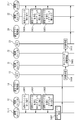
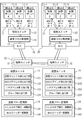
- the inter-virtual server communication identification system of the present invention includes a first physical server 10, a second physical server 20, and a network 30.
- the first physical server 10 and the second physical server 20 may be servers that can be connected to a network and realize an environment in which a virtual machine can operate. Therefore, other examples of the first physical server 10 and the second physical server 20 include mobile terminals, car navigation systems (car navigation systems), home game machines, interactive televisions, digital tuners, digital recorders, information home appliances (information home appliances). ), Office Automation (OA) equipment, etc. are also conceivable.
- the 1st physical server 10 and the 2nd physical server 20 may be mounted in mobile bodies, such as a vehicle, a ship, and an aircraft. However, actually, it is not limited to these examples.
- Examples of the network 30 include the Internet, a LAN (Local Area Network), a wireless LAN (Wireless LAN), a WAN (Wide Area Network), a backbone (Backbone), a fixed telephone network, a mobile phone network, and WiMAX (IEEE 802.16a).
- 3G (3rd Generation) leased line, cable TV (CATV) line, IrDA (Infrared Data Association), Bluetooth (registered trademark), serial communication line, and the like are assumed. However, actually, it is not limited to these examples.
- the network 30 includes a physical switch 31 and a physical switch 32.
- a virtual server “A” 11-1, a virtual server “B” 11-2, and a virtual server “C” 11-3 are shown.
- a virtual server “D” 21-1, a virtual server “E” 21-2, and a virtual server “F” 21-3 are shown.
- Examples of the virtual switch 12 and the virtual switch 22 include a hypervisor, a virtual machine monitor (VMM), and the like.
- the virtual switch 12 includes a virtual machine ID allocation unit 121, a MAC address allocation unit 122, and an IP address allocation unit 123.
- the virtual switch 22 includes a virtual machine ID assignment unit 221, a MAC address assignment unit 222, and an IP address assignment unit 223.
- the virtual machine ID assignment unit 121 and the virtual machine ID assignment unit 221 newly assign a VLAN ID that can be grasped and identified by an existing router or switch as a virtual machine ID (Virtual Machine identifier: VMid) corresponding to each virtual server. .
- VMid Virtual Machine identifier
- the virtual machine ID is identification information that does not depend on an existing communication protocol.
- the MAC address assignment unit 122 and the MAC address assignment unit 222 assign a MAC address to each virtual server.
- This MAC address is a private MAC address.
- the private MAC address can basically be set freely.
- the IP address assignment unit 123 and the IP address assignment unit 223 assign an IP address to each virtual server.
- This IP address is a private IP address.
- the first physical server 10 and the second physical server 20 can know the MAC address of the virtual server by an ARP (Address Resolution Protocol) command or table if the IP address of the counterpart virtual server is known.
- ARP Address Resolution Protocol
- each of a plurality of physical servers may use the same private IP address.
- the MAC address or virtual machine ID of each virtual server is used, and as the IP address of each virtual server, the IP address assigned to the NIC in the physical server, etc. It is also conceivable to share the host IP address. Therefore, the IP address of each virtual server may overlap.
- the NIC 13 and the NIC 23 are expansion cards for connecting a computer to a LAN (Local Area Network).
- the NIC 13 and the NIC 23 may be an antenna for wireless communication or a communication interface for connecting to a network other than the LAN. However, actually, it is not limited to these examples.
- the NIC 13 is connected to a physical switch 31 in the network 30.
- a physical switch 31 in the network 30 is connected to a physical switch 32 in the network 30.
- a physical switch 32 in the network 30 is connected to the NIC 23.
- two physical switches 31 and 32 are illustrated as relay physical switches, but in reality, the number of physical switches may be one or three or more.
- an open flow switch (Open Flow Switch) is assumed.
- an open flow controller (Open Flow Controller) that is a server that controls these communication flow processes together with the open flow switch.
- the network 30 includes the above-described OpenFlow controller.
- a router, a switching hub, and the like are also conceivable. However, actually, it is not limited to these examples.
- OpenFlow switch The details of the OpenFlow switch are described in the following documents. “OpenFlow Specification Version 0.9.0 (Wire Protocol 0x98) July 20, 2009 Current Maintainer: Brandon Heller (brandonh@stanford.w: // tu). openflowswitch. org / documents / openflow-spec-v0.9.0. pdf>
- the communication flow monitoring unit 14 and the communication flow monitoring unit 24 confirm the virtual machine ID (VMid) included in the received packet at the time of reception.
- Vid virtual machine ID
- the communication flow monitoring unit 14 includes at least one of a VLAN tag insertion / deletion unit 141 and a MAC header conversion unit 142.
- the communication flow monitoring unit 24 includes at least one of a VLAN tag insertion / deletion unit 241 and a MAC header conversion unit 242.
- the VLAN tag insertion / deletion unit 141 and the VLAN tag insertion / deletion unit 241 insert a virtual machine ID (VMid) as a VLAN tag into a transmission packet at the time of transmission, and delete a virtual machine ID (VMid) of the reception packet at the time of reception.
- VMid virtual machine ID
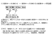
- the MAC header conversion unit 142 and the MAC header conversion unit 242 include “MAC DA (Destination Address)” and “MAC” included in the MAC-DA / SA field (MAC-DA / SA field) which is a MAC header field. A part or all of each area of “SA (Source Address: transmission source address)” is converted into a virtual machine ID (VMid) of the virtual server.
- MAC DA Denssion Address
- SA Transmission Source address
- the MAC header conversion unit 142 and the MAC header conversion unit 242 convert a part or all of the area of “MAC DA” to the virtual machine ID (VMid) of the virtual server of the transmission destination (destination), and further , Part or all of the area of “MAC SA” is converted into a virtual machine ID (VMid) of the virtual server of the transmission source.
- the communication flow monitoring unit 14 may be included in either the virtual switch 12 or the NIC 13.
- the communication flow monitoring unit 24 may be included in either the virtual switch 22 or the NIC 23.
- the communication flow monitoring unit 14 is provided between the NIC 13 and the physical switch 31, and the communication flow monitoring unit 24 is provided between the NIC 23 and the physical switch 32.
- the communication flow monitoring unit 14 is provided in a physical switch 31 (physical switch closest to the first computer 10) directly connected to the NIC 13, and the communication flow monitoring unit 24 is connected to the NIC 23 directly.
- 32 the physical switch closest to the second computer 20 is provided.
- the virtual switch 12 the virtual switch 22
- the communication flow monitoring unit 14 the communication flow
- Each of the monitoring units 24 is realized by a processor that is driven based on a software program and executes predetermined processing, and a memory that stores the program and various data.
- a CPU Central Processing Unit
- a microprocessor a microcontroller
- a semiconductor integrated circuit Integrated Circuit (IC) having a similar function
- semiconductor storage devices such as RAM (Random Access Memory), ROM (Read Only Memory), EEPROM (Electrically Erasable and Programmable Read Only Memory), and HDD Memory (SDHidK)
- RAM Random Access Memory
- ROM Read Only Memory
- EEPROM Electrically Erasable and Programmable Read Only Memory
- HDD Memory HDD Memory
- An auxiliary storage device such as State Drive) or a storage medium (media) such as a DVD (Digital Versatile Disk) or a memory card is conceivable.
- the memory is not limited to a storage device built in the computer main body, but may be a storage device installed in a peripheral device (external HDD or the like) or a server (Web server or file server or the like) in the network.
- the above memory may be DAS (Direct Attached Storage), FC-SAN (Fibre Channel-Storage Area Network), NAS (Network Attached Storage), IP-SAN (IP-Storage Storage, etc.). good.
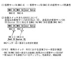
- VLAN Tag stack of virtual machine ID (VMid)
- VLAN Tag VLAN Tag
- a VLAN ID that can be grasped and identified by an existing router or switch is newly assigned as an ID (VMid) of each virtual machine by the virtual machine ID assigning unit.
- ID a VLAN ID that can be grasped and identified by an existing router or switch
- communication is performed by inserting a two-stage tag of “VMid-A” and “VMid-D” into the packet. That is, the two-stage tag is two virtual machine IDs (VMid) stacked as VLAN tags.
- a packet including “(Data packet)” is transmitted as a TCP / IP packet (Transmission Control Protocol / Internet Protocol Packet).
- TCP / IP packet Transmission Control Protocol / Internet Protocol Packet
- the VLAN tag insertion / deletion unit causes the transmission packet to receive 2 as shown in (2) of FIG.
- a stage tag is inserted (VLAN tag two stages are inserted) and transmitted to a physical switch in the network.
- the relay physical switch grasps the network state by monitoring only the VLAN tag field (VLAN Tag field) in the TCP / IP packet. That is, the relay physical switch monitors the VLAN tag area of the TCP / IP packet and collects information on the network state.
- VLAN Tag field VLAN Tag field
- a packet having the same identification information is defined by using an arbitrary combination of a MAC address area, a VLAN tag area, an IP address area, and a port number area as a set of identification information among TCP / IP packets.
- the concept is “flow”.
- the relay physical switch monitors only the VLAN tag field (TCP Tag field) among the TCP / IP packets, and packets having a common set of virtual machine IDs included in the VLAN tag area are regarded as the same flow. Capture information about the network status from the flow and destination of this flow and send it to the OpenFlow controller.
- the OpenFlow controller analyzes information about the collected network state and displays it on the management screen as necessary.
- the two-stage tag of the received packet is deleted by the VLAN tag insertion / deletion unit in the NIC or virtual switch, and then transmitted to the virtual server “D” on the receiving side.
- FIG. 3 shows a sequence diagram of communication flow control in the first embodiment of the present invention.
- Step S107 In the first physical server 10, during communication from the virtual server “A” 11-1 to the virtual server “D” 21-1, the virtual server “A” 11-1 on the transmission side receives “MAC DA” ⁇ “ “MAC SA” —generates a TCP / IP packet including “User Data” and outputs it to the virtual switch 12 as a transmission packet.
- the virtual switch 12 may generate a TCP / IP packet for each requesting virtual server 11 in response to a data transmission request from the transmitting-side virtual server 11.
- Step S108 The communication flow monitoring unit 14 confirms the transmission packet from the virtual switch 12.
- the VLAN tag insertion / deletion unit 141 of the communication flow monitoring unit 14 inserts a two-stage tag into the transmission packet and outputs it to the NIC 13.
- Step S109 The NIC 13 transmits the transmission packet to the physical switch 31 in the network.
- Step S110 The physical switch 31 transmits the transmission packet to the physical switch 32.
- the physical switch 32 transmits the transmission packet to the second physical server 20 on the reception side.
- the physical switch 31 and the physical switch 32 grasp the network state by monitoring the VLAN tag field (VLAN Tag field) in the transmission packet. That is, the physical switch 31 and the physical switch 32 monitor (monitor) the VLAN tag area of the TCP / IP packet and collect information regarding the network state.
- VLAN Tag field VLAN Tag field
- Step S111 In the second physical server 20 on the receiving side, the NIC 23 receives the transmission packet and outputs it as a reception packet to the communication flow monitoring unit 24.
- Step S112 The communication flow monitoring unit 24 confirms the received packet that has arrived at the NIC 23.
- the VLAN tag insertion / deletion unit 241 of the communication flow monitoring unit 24 deletes the two-stage tag of the received packet and outputs the received packet to the virtual switch 12.
- the virtual switch 12 transmits the received packet to the receiving virtual server “D” 21-1.
- the communication flow status between virtual machines can be grasped in the network with fields (areas) that can be grasped by existing routers and switches.
- the virtual machine ID assigning unit assigns each virtual machine ID (VMid) to a part or all of the MAC address area that can be grasped and identified by an existing router or switch.
- Vid virtual machine ID
- the virtual machine ID assigning unit assigns each virtual machine ID (VMid) to a part or all of the MAC address area that can be grasped and identified by an existing router or switch.
- the area is converted to the virtual machine ID “VMid-D” of the virtual server “D”, and part or all of the area of “MAC SA” is converted to the virtual machine ID “VMid-A” of the virtual server “A” To the physical switch in the network.
- the relay physical switch monitors the MAC-DA / SA field (MAC-DA / SA field), which is the MAC header area, in the TCP / IP packet to grasp the network status. That is, the relay physical switch monitors the MAC header area of the TCP / IP packet and collects information on the network state.
- MAC-DA / SA field which is the MAC header area
- the MAC-DA / SA (“MAC DA”, “MAC SA” part) of the received packet is converted to the original address by the MAC header conversion unit in the NIC or virtual switch, and then the receiving side To the virtual server “D”.
- FIG. 5 shows a sequence diagram of communication flow control in the second embodiment of the present invention.
- Step S207 In the first physical server 10 shown in FIG. 1, in the communication from the virtual server “A” 11-1 to the virtual server “D” 21-1, the transmitting-side virtual server “A” 11-1 A TCP / IP packet including “DA” — “MAC SA” — “User Data” is generated and output to the virtual switch 12 as a transmission packet.
- the virtual switch 12 may generate a TCP / IP packet for each requesting virtual server 11 in response to a data transmission request from the transmitting-side virtual server 11.
- Step S208 The communication flow monitoring unit 14 confirms the transmission packet from the virtual switch 12.
- the MAC header conversion unit 142 of the communication flow monitoring unit 14 converts part or all of the area of “MAC DA” into the virtual machine ID “VMid-D” of the virtual server “D” 21-1, A part or all of the area of “SA” is converted into the virtual machine ID “VMid-A” of the virtual server “A” 11-1, and the converted transmission packet is output to the NIC 13.
- Step S209 The NIC 13 transmits the transmission packet to the physical switch 31 in the network.
- Step S210 The physical switch 31 transmits the transmission packet to the physical switch 32.
- the physical switch 32 transmits the transmission packet to the second physical server 20 on the reception side.
- the physical switch 31 and the physical switch 32 grasp the network status by monitoring the MAC-DA / SA area (MAC-DA / SA field) which is the MAC header area. That is, the physical switch 31 and the physical switch 32 monitor (monitor) the MAC-DA / SA area of the TCP / IP packet and collect information regarding the network state.
- MAC-DA / SA area MAC-DA / SA field
- Step S211 In the second physical server 20 on the receiving side, the NIC 23 receives the transmission packet and outputs it as a reception packet to the communication flow monitoring unit 24.
- Step S212 The communication flow monitoring unit 24 confirms the received packet that has arrived at the NIC 23.
- the MAC header conversion unit 142 of the communication flow monitoring unit 24 converts the MAC-DA / SA (“MAC DA”, “MAC SA” portion) of the received packet into the original address, and outputs the received packet to the virtual switch 12. .
- the virtual switch 12 transmits the received packet to the receiving virtual server “D” 21-1.
- the communication flow state between virtual machines can be grasped in the network by using a field called MAC-DA / SA that can be grasped by an existing router or switch.
- MAC Header the case where a part or all of the MAC header (MAC Header) is converted into the virtual machine ID (VMid) has been described, but in reality, part or all of the IP header (IP Header) is converted. It is also possible to convert to a virtual machine ID (VMid). That is, part or all of at least one of the MAC header and the IP header (or both) may be converted into a virtual machine ID (VMid).
- VMid virtual machine ID
- a part or all of the MAC address area on the transmission side is converted into a virtual machine ID (VMid) on the transmission side, and a part or all of the IP address area on the reception side is converted to the virtual machine ID (VMid on the reception side).
- VMid virtual machine ID
- a part or all of the IP address area on the transmission side is converted into a virtual machine ID (VMid) on the transmission side
- a part or all of the MAC address area on the reception side is converted into a virtual machine ID (VMid) on the reception side. It is also possible to convert.
- the virtual machine ID assigning unit assigns each virtual machine ID (VMid) to a part or all of the MAC address area that can be grasped and identified by an existing router or switch.
- VMid virtual machine ID
- the virtual server “A” When communicating from the virtual server “A” to the virtual server “D”, it communicates as it is with packets with “MAC DA” and “MAC SA” which are MAC addresses to which each virtual machine ID (VMid) is assigned. .
- the virtual switch when assigning a MAC address to each virtual server, the virtual switch has a MAC address assignment unit, and the MAC address assignment unit assigns each virtual server to the virtual server as shown in (1) of FIG.
- a virtual machine ID of the virtual server is assigned to a part or all of the assigned MAC address.
- a MAC address corresponding to the virtual machine ID assigned to each of the virtual server “A” and the virtual server “D” is created by the MAC address assigning unit, and the created MAC address is assigned to the virtual server “A”. And virtual server “D”.
- the created MAC address has a case where a part of the MAC address area corresponds to the virtual machine ID and a case where the whole MAC address area corresponds to the virtual machine ID.
- the virtual server “A” on the transmission side sends a virtual machine ID to the MAC-DA / SA (“MAC DA”, “MAC SA” portion).
- a TCP / IP packet including
- the relay physical switch monitors only the MAC-DA / SA area (MAC-DA / SA field) included in the MAC address area of the TCP / IP packet to grasp the network state. That is, the relay physical switch monitors (monitors) the MAC-DA / SA area of the TCP / IP packet and collects information on the network state.
- MAC-DA / SA field included in the MAC address area of the TCP / IP packet to grasp the network state. That is, the relay physical switch monitors (monitors) the MAC-DA / SA area of the TCP / IP packet and collects information on the network state.
- part or all of the MAC address area of the transmission packet is converted into a virtual machine ID at the time of transmission, whereas in the third embodiment, a virtual address is assigned to the MAC address assigned to each virtual server in advance. The difference is that a machine ID is incorporated.
- a virtual machine ID can be used for a part or all of the MAC address area.
- FIG. 7 shows a sequence diagram of communication flow control in the third embodiment of the present invention.
- Step S307 In the first physical server 10, during communication from the virtual server “A” 11-1 to the virtual server “D” 21-1, the virtual server “A” 11-1 on the transmission side receives “MAC DA” ⁇ “ “MAC SA” —generates a TCP / IP packet including “User Data” and outputs it to the virtual switch 12 as a transmission packet.
- the virtual switch 12 may generate a TCP / IP packet for each requesting virtual server 11 in response to a data transmission request from the transmitting-side virtual server 11.
- the virtual switch 12 outputs the transmission packet to the NIC 13.
- the communication flow monitoring unit 14 is not used.
- Step S308 The NIC 13 transmits the transmission packet to the physical switch 31 in the network.
- Step S309 The physical switch 31 transmits the transmission packet to the physical switch 32.
- the physical switch 32 transmits the transmission packet to the second physical server 20 on the reception side.
- the physical switch 31 and the physical switch 32 grasp the network state by monitoring the MAC-DA / SA area which is the MAC header area in the transmission packet. That is, the physical switch 31 and the physical switch 32 monitor (monitor) the MAC-DA / SA area of the TCP / IP packet and collect information regarding the network state.
- Step S310 In the second physical server 20 on the reception side, the NIC 23 receives the transmission packet and outputs it as a reception packet to the virtual switch 12. The virtual switch 12 transmits the received packet to the receiving virtual server “D” 21-1.
- the communication flow state between virtual machines can be grasped in the network by a field called MAC-DA / SA that can be grasped by an existing router or switch.
- a virtual machine ID (VMid) is assigned to a MAC address
- a virtual machine ID (VMid) can also be assigned to an IP address. That is, it is possible to assign a virtual machine ID (VMid) to at least one (or both) of the MAC header and the IP header.
- VMid virtual machine ID
- VMid virtual machine ID
- VMid virtual machine ID
- the virtual machine ID assigning unit part or all of the MAC address area that can be grasped and identified by the existing router or switch, and the VLAN tag area
- An ID (VMid) of each virtual machine is assigned to a part or all of the bit space of part or all of the IP address area.
- the field of the transmission destination identification information (“MAC DA”, “VLAN Tag”, “IP DA”) in the header area of the flow represents the virtual machine ID of the virtual server “D”.
- a plurality of header fields are grouped so that the field of the original identification information (“MAC SA”, “VLAN Tag”, “IP SA”) represents the virtual machine ID of the virtual server “A”.
- the transmission-side physical server corresponds to the virtual machine ID assigned to each of the virtual server “A” and the virtual server “D”.
- a packet including a part or all of the MAC address area, a part or all of the VLAN tag area, and a part or all of the IP address area is transmitted to a TCP / IP packet.
- the destination identification information (“MAC DA”, “VLAN Tag”, “IP DA”) which is the header area of the flow—the source identification information (“MAC SA”)
- MAC SA the source identification information
- IP SA By monitoring a field of “VLAN Tag”, “IP SA”), that is, a set of a MAC address area, a VLAN tag area, and an IP address area, the network state is grasped.
- the relay physical switch collects information on the network state by monitoring a set of the MAC address area, the VLAN tag area, and the IP address area of the TCP / IP packet.
- the virtual machine ID is incorporated only in the MAC address assigned to each virtual server in advance, whereas in the fourth embodiment, the virtual machine ID is assigned to the MAC address and IP address assigned in advance to each virtual server. Is different in that a MAC packet, a VLAN tag, and a transmission packet using the IP address are created at the time of transmission. It is also possible not to provide a VLAN tag in the transmission packet.
- FIG. 9 shows a sequence diagram of communication flow control in the fourth embodiment of the present invention.
- Step S407 In the first physical server 10, during communication from the virtual server “A” 11-1 to the virtual server “D” 21-1, the virtual server “A” 11-1 on the transmission side receives “MAC DA” ⁇ “ A TCP / IP packet including “MAC SA” — “VLAN Tag” — “VLAN Tag” — “IP DA” — “IP SA” — “User Data” is generated and output to the virtual switch 12 as a transmission packet.
- the virtual switch 12 may generate a TCP / IP packet for each requesting virtual server 11 in response to a data transmission request from the transmitting-side virtual server 11. In practice, there may be no VLAN tag area “VLAN Tag”. The virtual switch 12 outputs the transmission packet to the NIC 13. Here, the communication flow monitoring unit 14 is not used.
- Step S408 The NIC 13 transmits the transmission packet to the physical switch 31 in the network.
- Step S409 The physical switch 31 transmits the transmission packet to the physical switch 32.
- the physical switch 32 transmits the transmission packet to the second physical server 20 on the reception side.
- the physical switch 31 and the physical switch 32 grasp the network state by monitoring the set of the MAC address area, the VLAN tag area, and the IP address area of the transmission packet. That is, the physical switch 31 and the physical switch 32 monitor a set of the MAC address area, the VLAN tag area, and the IP address area of the TCP / IP packet, and collect information on the network state.
- Step S410 In the second physical server 20 on the reception side, the NIC 23 receives the transmission packet and outputs it as a reception packet to the virtual switch 12. The virtual switch 12 transmits the received packet to the receiving virtual server “D” 21-1.
- destination identification information (“MAC DA”, “VLAN Tag”, “IP DA”) which is the header area of the flow—source identification information (“MAC SA”, “VLAN Tag”, “IP SA”)
- MAC SA header area of the flow—source identification information
- IP SA IP Security
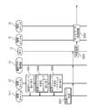
- FIG. 10 describes an environment in which a multi-tenant environment is connected to a data center from a plurality of VPNs via a VPN router as an example of a use environment of the inter-virtual server communication identification system.
- the inter-virtual server communication identification system of the present invention includes a first physical server 10, a second physical server 20, a network 30, and a virtual network 40.
- the first physical server 10, the second physical server 20, and the network 30 are basically the same as those shown in FIG.
- the second physical server 20 is a server in a data center of a multi-tenant environment.
- a virtual server “D1” 21-4, a virtual server “D2” 21-5, and a virtual server “D3” 21-6 are shown.
- the virtual server “D1” 21-4, the virtual server “D2” 21-5, and the virtual server “D3” 21-6 correspond to the virtual server “D” 21-1 illustrated in FIG.
- the virtual network 40 includes a VPN router 41, a VPN router 42, a VPN router 43, and a VPN router 44.
- the VPN router 41 is connected to the physical switch 32.
- the VPN router 42 is connected to a server corresponding to the virtual server “D” 21-1 shown in FIG. 1 among the servers in the data center of the multi-tenant environment.
- the VPN router 42 is connected to the second physical server 20.
- the VPN router 43 is connected to a server corresponding to the virtual server “E” 21-2 shown in FIG. 1 among the servers in the data center of the multi-tenant environment.
- the VPN router 44 is connected to a server corresponding to the virtual server “F” 21-3 shown in FIG. 1 among the servers in the data center of the multi-tenant environment.
- a virtual machine ID is assigned to a MAC address or an IP address in advance by a virtual machine ID assigning unit, a MAC address assigning unit, and an IP address assigning unit.
- An ID can be assigned.
- the assigned packet is appended with “MAC DA”, “MAC SA”, “VLAN Tag”, “IP DA”, “IP SA” Send the packet.
- the transmission destination identification information (“MAC DA”, “VLAN Tag”, “IP DA”) represents the virtual machine ID of the virtual server “D”
- the transmission source identification information (“MAC DA”, “VLAN Tag”, “IP DA”) group the multiple header fields as representing the virtual machine ID of the virtual server “A”.
- VLAN Tag there may be a case where there is no VLAN tag area “VLAN Tag”.
- virtual server “A” (VMid-A) and virtual server“ B ”(VMid-B) communicate in the address space consisting of the above headers even under the situation where the same private IP address (Private IP address) is assigned. Therefore, communication is possible without address collision.
- the relay physical switch among the TCP / IP packets, the destination identification information (“MAC DA”, “VLAN Tag”, “IP DA”) which is the header area of the flow—source identification information (“MAC SA”), By monitoring the fields of “VLAN Tag” and “IP SA”), the network status is grasped. That is, the relay physical switch monitors (monitors) a set of transmission destination identification information and transmission source identification information area of the TCP / IP packet, and collects information on the network state.
- MAC DA the destination identification information
- IP MAC SA the header area of the flow—source identification information
- VPNid the VPN ID
- IP DA IP address
- packet transfer method there are a “layer 2 encapsulation method”, a “layer 3 encapsulation method”, and the like.
- the layer 2 packet (Layer 2 packet) area (“MAC DA”, “MAC SA”, “VLAN Tag”, “IP DA”, “IP SA”, “ User Data ”) is encapsulated as it is and transferred with VPNid.
- IP layer IP layer
- IP SA IP SA
- User Data IP layer
- the receiving physical server sends the received packet to the receiving virtual server “D”.
- 12A and 12B show sequence diagrams of communication flow control in the fifth embodiment of the present invention.
- Step S507 In the first physical server 10, during communication from the virtual server “A” 11-1 to the virtual server “D” 21-1, the virtual server “A” 11-1 on the transmission side receives “MAC DA” ⁇ “ A TCP / IP packet including “MAC SA” — “VLAN Tag” — “VLAN Tag” — “IP DA” — “IP SA” — “User Data” is generated and output to the virtual switch 12 as a transmission packet.
- the virtual switch 12 may generate a TCP / IP packet for each requesting virtual server 11 in response to a data transmission request from the transmitting-side virtual server 11. In practice, there may be no VLAN tag area “VLAN Tag”. The virtual switch 12 outputs the transmission packet to the NIC 13. Here, the communication flow monitoring unit 14 is not used.
- Step S508 The NIC 13 transmits the transmission packet to the physical switch 31 in the network.
- Step S509 The physical switch 31 transmits the transmission packet to the physical switch 32.
- the physical switch 32 transmits the transmission packet to the VPN router 41.
- the physical switch 31 and the physical switch 32 include transmission destination identification information (“MAC DA”, “VLAN Tag”, “IP DA”) in the transmission packet—transmission source identification information (“MAC SA”, “VLAN”).
- MAC DA transmission destination identification information
- IP DA transmission source identification information
- the network status is grasped by monitoring the fields of “Tag” and “IP SA”). That is, the physical switch 31 and the physical switch 32 monitor (monitor) a pair of transmission destination identification information and transmission source identification information area of the TCP / IP packet, and collect information on the network state.
- Step S510 When the VPN router 41 receives the transmission packet from the physical switch 32, the VPN router 41 appropriately uses part or all of the MAC address area, part or all of the VLAN tag area, and part or all of the IP address area of the transmission packet. Encode and generate an encapsulated packet. Further, the VPN router 41 recognizes which VPNid from the ID space of the above-mentioned area, and determines the transfer destination of the encapsulated packet. Here, it is assumed that the ID space of the area corresponds to “VPNid-D”.
- the VPN router 41 adds “VPNid-D” to the encapsulated packet and transfers it to the VPN router 42.
- the “layer 2 encapsulation method” and the “layer 3 encapsulation method”, which are packet transfer methods, are as described above.
- the VPN router 42 decodes the encapsulated packet to return it to the form of the transmission packet, and transmits the transmission packet to the second physical server 20.
- Step S511 In the second physical server 20 on the reception side, the NIC 23 receives the transmission packet and outputs it as a reception packet to the virtual switch 12.
- the virtual switch 12 determines the virtual server that is the transmission destination of the received packet according to the congestion degree of each virtual server in the second physical server 20, the port number specified by the received packet, and the like. Here, the virtual switch 12 transmits the received packet to the virtual server “D1” 21-4.
- the inter-virtual server communication identification system of the present invention includes a first physical server 10, a second physical server 20, a network 30, and a virtual network 40.
- the first physical server 10, the second physical server 20, and the network 30 are basically the same as those shown in FIG.
- the virtual switch 12 further includes a group allocation unit 124 in addition to the virtual machine ID allocation unit 121, the MAC address allocation unit 122, and the IP address allocation unit 123.
- the virtual switch 22 further includes a group allocation unit 224 in addition to the virtual machine ID allocation unit 221, the MAC address allocation unit 222, and the IP address allocation unit 223.
- the virtual machine ID assignment unit 121, the MAC address assignment unit 122, the IP address assignment unit 123, the virtual machine ID assignment unit 221, the MAC address assignment unit 222, and the IP address assignment unit 223 are basically shown in FIG. It is the same as that shown in.
- a group ID indicating a group is assigned.
- VLAN ID is assumed as the group ID.
- the group ID of the first VLAN group is “GP-1”.
- the group ID of the second VLAN group is “GP-2”.
- a virtual server “A” 11-1, a virtual server “B” 11-2, a virtual server “D” 21-1, and a virtual server “E” 21-2 belong to the first VLAN group “GP-1” And
- the virtual server “A” 11-1, the virtual server “B” 11-2, the virtual server “D” 21-1, and the virtual server “E” 21-2 can communicate with each other.
- “C” 11-3 and virtual server “F” 21-3 cannot communicate with each other because the VLAN groups are different.
- VLAN ID group ID
- the group ID is assigned to the VLAN tag area by the virtual server when the transmission packet is transmitted over the network.
- the assignment of the virtual machine ID to the transmission packet is according to another embodiment.
- the MAC address area, VLAN tag area, IP address area, and at least one of these three areas include the virtual machine ID (Dest ID) of the destination virtual server and the source A virtual machine ID (Source ID) of the virtual server is assigned.
- These virtual machine IDs are preferably assigned to the same area, but may actually be assigned to different areas.
- ⁇ Summary> in an inter-virtual server communication identification system between logical servers operating on a physical server, end-to-end communication settings between logical servers, communication identification, performance monitoring, end- It is characterized by providing a mechanism for grasping the situation such as to-End failure diagnosis.
- the present invention has the following effects.
- the first effect is that since the ID area of the virtual machine is encoded using the header area of the existing packet, the communication state between the virtual machines can be grasped in the environment including the existing switch and router environments. It is.
- the second effect is that since the entire plurality of areas of the existing packet header are recognized as the virtual machine ID space, the communication state between the virtual machines can be grasped in an environment including existing switches and router environments. is there.
- the third effect is that the entire plurality of areas of the existing packet header are recognized as the virtual machine ID space, so that communication is possible even if the IP addresses assigned to the virtual machines are the same in a multi-tenant environment. It is.
- a storage medium storing a program for causing a computer to execute a step of transmitting a transmission packet to which a machine ID is assigned on a network.
- (Appendix 2) The storage medium according to attachment 1, wherein Inserting a VLAN tag area including the virtual machine ID into the transmission packet when transmitting the transmission packet over a network;
- a storage medium storing a program for causing a computer to further execute a step of deleting a VLAN tag area of a received packet from a network and transmitting the packet to the virtual server.
- Appendix 3 The storage medium according to appendix 1 or 2, A storage medium storing a program for causing a computer to further execute a step of converting at least a part of an address area into the virtual machine ID in a header area of the transmission packet when the transmission packet is transmitted over a network.
- Appendix 4 A storage medium according to any one of appendices 1 to 3, Incorporating the virtual machine ID of the receiving side into at least one of a MAC address or an IP address, and allocating the MAC address and the IP address to the virtual server; Storing a program for causing the computer to further execute the step of assigning the MAC address to the MAC address area of the transmission packet and assigning the IP address to the IP address area of the transmission packet when generating the transmission packet Medium.
- Appendix 5 The storage medium according to appendix 4, wherein Assigning the virtual machine ID to the virtual server;
- a storage medium storing a program for causing a computer to further execute a step of assigning the virtual machine ID to a VLAN tag area of the transmission packet when generating the transmission packet.
- Appendix 6 A storage medium according to any one of appendices 1 to 5, VLAN as group ID for the virtual server Assigning an ID; VLAN assigned as a group ID to the virtual server VLAN whose ID is assigned as a group ID to the receiving virtual server When the ID is the same as the ID, the VLAN in the VLAN tag area of the transmission packet A storage medium storing a program for causing a computer to execute the step of assigning an ID.
Abstract
Description
第1の問題については、以下の通りである。
どの論理サーバ間の通信がどのような状態になっているかについて、既存のルータやスイッチでは、既存のトラヒックに新たな識別子としてのプロトコルヘッダを追加することが無い。そのため、論理サーバに割り当てられたMACアドレス(Media Access Control address)、IPアドレス(Internet Protocol address)、VLAN ID(Virtual Local Area Network - identifier)等で通信を行ったとしても、それらの通信がどの経路を通っているのか、通信性能がどうなのか、通信障害が起こったときにその通信障害がどこで起こっているのか、といった状況をリアルタイムにネットワーク管理者が把握することが困難であった。
第2の問題については、以下の通りである。
データセンター等でのマルチテナントでの運用形態の場合に、マルチテナント間での仮想マシンの通信を行う際に、IPアドレスが重複する場合がある。その場合には、IPアドレスの再割り当て(Renumbering)か、あるいはNAT(Network Address Translation)によるアドレス変換か、をしない限り、通信を実施することが不可能であった。しかし、IPアドレスの再割り当ては、サービスを止める必要があり、大きな負荷がかかる。なお、NATには、IPマスカレード等のNAPT(Network Address Port Translation)も含むものとする。また、NATは、アプリケーション依存性があるため、アプリケーションの整合を確認しない限り利用できなかった。そのため、マルチテナント環境での仮想マシン間の通信で問題を起こすケースがあった。
図1に示すように、本発明の仮想サーバ間通信識別システムは、第1物理サーバ10と、第2物理サーバ20と、ネットワーク30を含む。
[仮想マシンID(VMid)のVLAN Tag stack利用]
図2を参照して、仮想マシンID(VMid)をVLANタグ(VLAN Tag)としてスタック(stack)して利用する場合について説明する。
図1に示す第1物理サーバ10において、仮想スイッチ12の仮想マシンID割り当て部121は、各仮想サーバ11(11-i、i=1~n)に仮想マシンIDを割り当てる。
また、仮想スイッチ12のMACアドレス割り当て部122は、各仮想サーバ11(11-i、i=1~n)にMACアドレスを割り当てる。
また、仮想スイッチ12のIPアドレス割り当て部122は、各仮想サーバ11(11-i、i=1~n)にIPアドレスを割り当てる。
同様に、第2物理サーバ20において、仮想スイッチ22の仮想マシンID割り当て部221は、各仮想サーバ21(21-i、i=1~n)に仮想マシンIDを割り当てる。
また、仮想スイッチ22のMACアドレス割り当て部222は、各仮想サーバ21(21-i、i=1~n)にMACアドレスを割り当てる。
また、仮想スイッチ22のIPアドレス割り当て部222は、各仮想サーバ21(21-i、i=1~n)にIPアドレスを割り当てる。
第1物理サーバ10において、仮想サーバ「A」11-1から仮想サーバ「D」21-1への通信の際に、送信側の仮想サーバ「A」11-1は、「MAC DA」 - 「MAC SA」 - 「User Data」を含むTCP/IPパケットを生成し、送信パケットとして仮想スイッチ12に出力する。なお、実際には、送信側の仮想サーバ11からのデータ送信要求に応じて、仮想スイッチ12が、要求元の仮想サーバ11毎にTCP/IPパケットを生成するようにしても良い。
通信フロー監視部14は、仮想スイッチ12からの送信パケットを確認する。通信フロー監視部14のVLANタグ挿入・削除部141は、送信パケットに2段タグを挿入して、NIC13に出力する。
NIC13は、送信パケットをネットワーク内の物理スイッチ31へ送信する。
物理スイッチ31は、送信パケットを物理スイッチ32へ送信する。物理スイッチ32は、送信パケットを受信側の第2物理サーバ20に送信する。このとき、物理スイッチ31及び物理スイッチ32は、送信パケットのうち、VLANタグ領域(VLAN Tag field)をモニターすることで、ネットワーク状態を把握する。すなわち、物理スイッチ31及び物理スイッチ32は、TCP/IPパケットのVLANタグ領域をモニター(監視)して、ネットワーク状態に関する情報を収集する。
受信側の第2物理サーバ20において、NIC23は、送信パケットを受信し、受信パケットとして通信フロー監視部24に出力する。
通信フロー監視部24は、NIC23に到着した受信パケットを確認する。通信フロー監視部24のVLANタグ挿入・削除部241は、受信パケットの2段タグを削除し、受信パケットを仮想スイッチ12に出力する。仮想スイッチ12は、受信パケットを受信側の仮想サーバ「D」21-1へ送信する。
[仮想マシンID(VMid)のMAC Header変換形態]
図4を参照して、MACヘッダー(MAC Header)の一部又は全部を仮想マシンID(VMid)に変換する場合について説明する。ここでは、MACヘッダーを例に説明するが、IPヘッダーの場合も基本的に同様である。なお、MACヘッダーは、TCP/IPパケットのMACアドレス領域を示し、IPヘッダーは、TCP/IPパケットのIPアドレス領域を示すものとする。
図1に示す第1物理サーバ10において、仮想スイッチ12の仮想マシンID割り当て部121は、各仮想サーバ11(11-i、i=1~n)に仮想マシンIDを割り当てる。
また、仮想スイッチ12のMACアドレス割り当て部122は、各仮想サーバ11(11-i、i=1~n)にMACアドレスを割り当てる。
また、仮想スイッチ12のIPアドレス割り当て部122は、各仮想サーバ11(11-i、i=1~n)にIPアドレスを割り当てる。
同様に、第2物理サーバ20において、仮想スイッチ22の仮想マシンID割り当て部221は、各仮想サーバ21(21-i、i=1~n)に仮想マシンIDを割り当てる。
また、仮想スイッチ22のMACアドレス割り当て部222は、各仮想サーバ21(21-i、i=1~n)にMACアドレスを割り当てる。
また、仮想スイッチ22のIPアドレス割り当て部222は、各仮想サーバ21(21-i、i=1~n)にIPアドレスを割り当てる。
図1に示す第1物理サーバ10において、仮想サーバ「A」11-1から仮想サーバ「D」21-1への通信の際に、送信側の仮想サーバ「A」11-1は、「MAC DA」 - 「MAC SA」 - 「User Data」を含むTCP/IPパケットを生成し、送信パケットとして仮想スイッチ12に出力する。なお、実際には、送信側の仮想サーバ11からのデータ送信要求に応じて、仮想スイッチ12が、要求元の仮想サーバ11毎にTCP/IPパケットを生成するようにしても良い。
通信フロー監視部14は、仮想スイッチ12からの送信パケットを確認する。通信フロー監視部14のMACヘッダー変換部142は、「MAC DA」の一部又は全部の領域を仮想サーバ「D」21-1の仮想マシンID「VMid-D」に変換し、更に、「MAC SA」の一部又は全部の領域を仮想サーバ「A」11-1の仮想マシンID「VMid-A」に変換して、変換後の送信パケットをNIC13に出力する。
NIC13は、送信パケットをネットワーク内の物理スイッチ31へ送信する。
物理スイッチ31は、送信パケットを物理スイッチ32へ送信する。物理スイッチ32は、送信パケットを受信側の第2物理サーバ20に送信する。このとき、物理スイッチ31及び物理スイッチ32は、MACヘッダー領域であるMAC-DA/SA領域(MAC-DA/SA field)をモニターすることで、ネットワーク状態を把握する。すなわち、物理スイッチ31及び物理スイッチ32は、TCP/IPパケットのMAC-DA/SA領域をモニター(監視)して、ネットワーク状態に関する情報を収集する。
受信側の第2物理サーバ20において、NIC23は、送信パケットを受信し、受信パケットとして通信フロー監視部24に出力する。
通信フロー監視部24は、NIC23に到着した受信パケットを確認する。通信フロー監視部24のMACヘッダー変換部142は、受信パケットのMAC-DA/SA(「MAC DA」、「MAC SA」部分)を元のアドレスに変換し、受信パケットを仮想スイッチ12に出力する。仮想スイッチ12は、受信パケットを受信側の仮想サーバ「D」21-1へ送信する。
[仮想マシンID(VMid)のMACアドレス割り当て形態]
図6を参照して、予めMACアドレスに仮想マシンID(VMid)を割り当てる場合について説明する。ここでは、MACアドレスに仮想マシンID(VMid)を割り当てる場合について説明するが、IPアドレスに仮想マシンID(VMid)を割り当てる場合も基本的に同様である。
図1に示す第1物理サーバ10において、仮想スイッチ12の仮想マシンID割り当て部121は、各仮想サーバ11(11-i、i=1~n)に仮想マシンIDを割り当てる。
また、仮想スイッチ12のMACアドレス割り当て部122は、各仮想サーバ11(11-i、i=1~n)にMACアドレスを割り当てる際、仮想サーバ「A」11-1のMACアドレス領域の一部又は全部の領域に仮想サーバ「A」11-1の仮想マシンID「VMid-A」を使用したMACアドレスを割り当てる。
また、仮想スイッチ12のIPアドレス割り当て部122は、各仮想サーバ11(11-i、i=1~n)にIPアドレスを割り当てる。
同様に、第2物理サーバ20において、仮想スイッチ22の仮想マシンID割り当て部221は、各仮想サーバ21(21-i、i=1~n)に仮想マシンIDを割り当てる。
また、仮想スイッチ22のMACアドレス割り当て部222は、各仮想サーバ21(21-i、i=1~n)にMACアドレスを割り当てる際、仮想サーバ「D」21-1のMACアドレス領域の一部又は全部の領域に仮想サーバ「D」21-1の仮想マシンID「VMid-D」を使用したMACアドレスを割り当てる。
また、仮想スイッチ22のIPアドレス割り当て部222は、各仮想サーバ21(21-i、i=1~n)にIPアドレスを割り当てる。
第1物理サーバ10において、仮想サーバ「A」11-1から仮想サーバ「D」21-1への通信の際に、送信側の仮想サーバ「A」11-1は、「MAC DA」 - 「MAC SA」 - 「User Data」を含むTCP/IPパケットを生成し、送信パケットとして仮想スイッチ12に出力する。
NIC13は、送信パケットをネットワーク内の物理スイッチ31へ送信する。
物理スイッチ31は、送信パケットを物理スイッチ32へ送信する。物理スイッチ32は、送信パケットを受信側の第2物理サーバ20に送信する。
受信側の第2物理サーバ20において、NIC23は、送信パケットを受信し、受信パケットとして仮想スイッチ12に出力する。仮想スイッチ12は、受信パケットを受信側の仮想サーバ「D」21-1へ送信する。
[仮想マシンID(VMid)のIP+MAC addr割り当て形態]
図8を参照して、仮想マシンID(VMid)をMACアドレス領域、VLANタグ領域、及びIPアドレス領域のそれぞれに割り当てる場合について説明する。
図1に示す第1物理サーバ10において、仮想スイッチ12の仮想マシンID割り当て部121は、各仮想サーバ11(11-i、i=1~n)に仮想マシンIDを割り当てる。
また、仮想スイッチ12のMACアドレス割り当て部122は、各仮想サーバ11(11-i、i=1~n)にMACアドレスを割り当てる際、仮想サーバ「A」11-1のMACアドレス領域の一部又は全部の領域に仮想サーバ「A」11-1の仮想マシンID「VMid-A」を使用したMACアドレスを割り当てる。
また、仮想スイッチ12のIPアドレス割り当て部122は、各仮想サーバ11(11-i、i=1~n)にIPアドレスを割り当てる際、仮想サーバ「A」11-1のIPアドレス領域の一部又は全部の領域に仮想サーバ「A」11-1の仮想マシンID「VMid-A」を使用したIPアドレスを割り当てる。
同様に、第2物理サーバ20において、仮想スイッチ22の仮想マシンID割り当て部221は、各仮想サーバ21(21-i、i=1~n)に仮想マシンIDを割り当てる。
また、仮想スイッチ22のMACアドレス割り当て部222は、各仮想サーバ21(21-i、i=1~n)にMACアドレスを割り当てる際、仮想サーバ「D」21-1のMACアドレス領域の一部又は全部の領域に仮想サーバ「D」21-1の仮想マシンID「VMid-D」を使用したMACアドレスを割り当てる。
また、仮想スイッチ22のIPアドレス割り当て部222は、各仮想サーバ21(21-i、i=1~n)にIPアドレスを割り当てる際、仮想サーバ「D」21-1のIPアドレス領域の一部又は全部の領域に仮想サーバ「D」21-1の仮想マシンID「VMid-D」を使用したIPアドレスを割り当てる。
第1物理サーバ10において、仮想サーバ「A」11-1から仮想サーバ「D」21-1への通信の際に、送信側の仮想サーバ「A」11-1は、「MAC DA」 - 「MAC SA」 - 「VLAN Tag」 - 「VLAN Tag」 - 「IP DA」 - 「IP SA」 - 「User Data」を含むTCP/IPパケットを生成し、送信パケットとして仮想スイッチ12に出力する。
NIC13は、送信パケットをネットワーク内の物理スイッチ31へ送信する。
物理スイッチ31は、送信パケットを物理スイッチ32へ送信する。物理スイッチ32は、送信パケットを受信側の第2物理サーバ20に送信する。
受信側の第2物理サーバ20において、NIC23は、送信パケットを受信し、受信パケットとして仮想スイッチ12に出力する。仮想スイッチ12は、受信パケットを受信側の仮想サーバ「D」21-1へ送信する。
[仮想NW(ネットワーク)ID利用]
図10、図11を参照して、仮想NWのIDとして、VPN(Virtual Private Network) IDや、VLAN IDを利用する事例について説明する。ここでは、VPN ID(VPNid)を例に説明する。
図1に示す第1物理サーバ10において、仮想スイッチ12の仮想マシンID割り当て部121は、各仮想サーバ11(11-i、i=1~n)に仮想マシンIDを割り当てる。
また、仮想スイッチ12のMACアドレス割り当て部122は、各仮想サーバ11(11-i、i=1~n)にMACアドレスを割り当てる際、仮想サーバ「A」11-1のMACアドレス領域の一部又は全部の領域に仮想サーバ「A」11-1の仮想マシンID「VMid-A」を使用したMACアドレスを割り当てる。
また、仮想スイッチ12のIPアドレス割り当て部122は、各仮想サーバ11(11-i、i=1~n)にIPアドレスを割り当てる際、仮想サーバ「A」11-1のIPアドレス領域の一部又は全部の領域に仮想サーバ「A」11-1の仮想マシンID「VMid-A」を使用したIPアドレスを割り当てる。
同様に、第2物理サーバ20において、仮想スイッチ22の仮想マシンID割り当て部221は、各仮想サーバ21(21-i、i=1~n)に仮想マシンIDを割り当てる。
また、仮想スイッチ22のMACアドレス割り当て部222は、各仮想サーバ21(21-i、i=1~n)にMACアドレスを割り当てる際、仮想サーバ「D」21-1のMACアドレス領域の一部又は全部の領域に仮想サーバ「D」21-1の仮想マシンID「VMid-D」を使用したMACアドレスを割り当てる。
また、仮想スイッチ22のIPアドレス割り当て部222は、各仮想サーバ21(21-i、i=1~n)にIPアドレスを割り当てる際、仮想サーバ「D」21-1のIPアドレス領域の一部又は全部の領域に仮想サーバ「D」21-1の仮想マシンID「VMid-D」を使用したIPアドレスを割り当てる。
第1物理サーバ10において、仮想サーバ「A」11-1から仮想サーバ「D」21-1への通信の際に、送信側の仮想サーバ「A」11-1は、「MAC DA」 - 「MAC SA」 - 「VLAN Tag」 - 「VLAN Tag」 - 「IP DA」 - 「IP SA」 - 「User Data」を含むTCP/IPパケットを生成し、送信パケットとして仮想スイッチ12に出力する。
NIC13は、送信パケットをネットワーク内の物理スイッチ31へ送信する。
物理スイッチ31は、送信パケットを物理スイッチ32へ送信する。物理スイッチ32は、送信パケットをVPNルータ41に送信する。
VPNルータ41は、物理スイッチ32から送信パケットを受け取ると、送信パケットのうち、MACアドレス領域の一部又は全部、VLANタグ領域の一部又は全部、IPアドレス領域の一部又は全部を適宜使ってエンコードし、カプセル化パケットを生成する。また、VPNルータ41は、上記の領域のID空間から、どのVPNidかを認識し、カプセル化パケットの転送先を決定する。ここでは、上記の領域のID空間が、「VPNid-D」に対応するものとする。
受信側の第2物理サーバ20において、NIC23は、送信パケットを受信し、受信パケットとして仮想スイッチ12に出力する。仮想スイッチ12は、第2物理サーバ20内の各仮想サーバの混雑度や、受信パケットで指定されているポート番号等に応じて、受信パケットの送信先となる仮想サーバを決定する。ここでは、仮想スイッチ12は、受信パケットを仮想サーバ「D1」21-4へ送信する。
[グループID利用]
図13を参照して、各仮想サーバについて、VLAN等の仮想的なグループ分けを行い、同一グループの仮想サーバ間でのみ通信可能とする事例について説明する。
について説明する。
なお、上記の各実施形態は、組み合わせて実施することも可能である。
以上のように、本発明は、物理サーバ上で複数動作する論理サーバ間の仮想サーバ間通信識別システムにおいて、論理サーバ間のEnd-to-Endでの通信設定、通信識別、性能監視、End-to-End障害診断等の状況を把握する機構を設けたことを特徴としている。
上記の実施形態の一部又は全部は、以下の付記のように記載することも可能である。但し、実際には、以下の記載例に限定されない。
仮想マシンID(Virtual Machine identifier)が割り当てられた仮想サーバの通信を制御するステップと、
前記仮想サーバと他の仮想サーバとの間のネットワークを介した通信の際、TCP/IPパケット(Transmission Control Protocol/Internet Protocol Packet)の形式で、データ以外のビット空間のうち少なくとも一部に前記仮想マシンIDが割り当てられている送信パケットをネットワーク上に送信するステップと
をコンピュータに実行させるためのプログラムを格納した
記憶媒体。
付記1に記載の記憶媒体であって、
前記送信パケットをネットワーク上に送信する際、前記送信パケットに前記仮想マシンIDを含むVLANタグ領域を挿入するステップと、
ネットワーク上からの受信パケットのVLANタグ領域を削除して前記仮想サーバに送信するステップと
を更にコンピュータに実行させるためのプログラムを格納した
記憶媒体。
付記1又は2に記載の記憶媒体であって、
前記送信パケットをネットワーク上に送信する際、前記送信パケットのヘッダー領域において、アドレス領域の少なくとも一部を前記仮想マシンIDに変換するステップを更にコンピュータに実行させるためのプログラムを格納した
記憶媒体。
付記1乃至3のいずれかに記載の記憶媒体であって、
MACアドレス或いはIPアドレスの少なくとも一方に前記受信側の仮想マシンIDを組み込み、前記仮想サーバに対して、前記MACアドレスと、前記IPアドレスと、を割り当てるステップと、
前記送信パケットを生成する際、前記送信パケットのMACアドレス領域に前記MACアドレスを割り当て、前記送信パケットのIPアドレス領域に前記IPアドレスを割り当てるステップと
を更にコンピュータに実行させるためのプログラムを格納した
記憶媒体。
付記4に記載の記憶媒体であって、
前記仮想サーバに対して、前記仮想マシンIDを割り当てるステップと、
前記送信パケットを生成する際、更に、前記送信パケットのVLANタグ領域に前記仮想マシンIDを割り当てるステップと
を更にコンピュータに実行させるためのプログラムを格納した
記憶媒体。
付記1乃至5のいずれかに記載の記憶媒体であって、
前記仮想サーバに対して、グループIDとしてVLAN
IDを割り当てるステップと、
前記仮想サーバに対してグループIDとして割り当てられたVLAN
IDが、受信側の仮想サーバに対してグループIDとして割り当てられたVLAN
IDと同じである場合、前記送信パケットのVLANタグ領域に当該VLAN
IDを割り当てるステップと
を更にコンピュータに実行させるためのプログラムを格納した
記憶媒体。
Claims (22)
- 受信側の仮想サーバに対して、受信側の仮想マシンID(Virtual Machine identifier)を割り当てる受信側の物理サーバと、
送信側の仮想サーバに対して、送信側の仮想マシンIDを割り当て、前記送信側の仮想サーバから前記受信側の仮想サーバへの送信パケットを生成する場合、TCP/IPパケット(Transmission Control Protocol/Internet Protocol Packet)の形式で、前記送信パケットのデータ以外のビット空間のうち少なくとも一部に、前記受信側の仮想マシンIDと前記送信側の仮想マシンIDとを割り当て、前記送信パケットを送信する送信側の物理サーバと、
前記送信側の物理サーバと前記受信側の物理サーバとを接続するネットワーク上に存在し、前記送信側の物理サーバと前記受信側の物理サーバとの間で前記送信パケットを中継する場合、前記送信パケットのデータ以外のビット空間に含まれる、前記受信側の仮想マシンIDと、前記送信側の仮想マシンIDと、に基づいて、前記送信パケットを識別し、ネットワーク状態を示す情報を収集する物理スイッチと
を含む
仮想サーバ間通信識別システム。 - 請求項1に記載の仮想サーバ間通信識別システムであって、
前記送信側の物理サーバは、
前記送信パケットに、前記受信側の仮想マシンIDと前記送信側の仮想マシンIDとを含むVLAN(Virtual Local Area Network)タグ領域を挿入するVLANタグ挿入部
を具備し、
前記受信側の物理サーバは、
前記送信パケットを受信した場合、前記送信パケットから前記VLANタグ領域を削除するVLANタグ削除部
を具備する
仮想サーバ間通信識別システム。 - 請求項1又は2に記載の仮想サーバ間通信識別システムであって、
前記送信側の物理サーバは、
前記送信パケットのヘッダー領域において、受信側のアドレス領域の少なくとも一部を前記受信側の仮想マシンIDに変換し、送信側のアドレス領域の少なくとも一部を前記送信側の仮想マシンIDに変換するヘッダー変換部
を具備する
仮想サーバ間通信識別システム。 - 請求項1乃至3のいずれか一項に記載の仮想サーバ間通信識別システムであって、
前記受信側の物理サーバは、
受信側のMACアドレス及び受信側のIPアドレスの少なくとも一方に前記受信側の仮想マシンIDを組み込み、前記受信側の仮想サーバに対して、前記受信側のMACアドレスと、前記受信側のIPアドレスと、を割り当てる受信側アドレス割り当て部
を具備し、
前記送信側の物理サーバは、
送信側のMACアドレス及び送信側のIPアドレスの少なくとも一方に前記送信側の仮想マシンIDを組み込み、前記送信側の仮想サーバに対して、前記送信側のMACアドレスと、前記送信側のIPアドレスと、を割り当てる送信側アドレス割り当て部
を具備し、
前記送信側の仮想サーバは、前記送信パケットを生成する際、前記送信パケットのMACアドレス領域に、前記受信側のMACアドレスと、前記送信側のMACアドレスと、を割り当て、前記送信パケットのIPアドレス領域に、前記受信側のIPアドレスと、前記送信側のIPアドレスと、を割り当てる
仮想サーバ間通信識別システム。 - 請求項4に記載の仮想サーバ間通信識別システムであって、
前記受信側の物理サーバは、
前記受信側の仮想サーバに対して、前記受信側の仮想マシンIDを割り当てる仮想マシンID割り当て部
を更に具備し、
前記送信側の物理サーバは、
前記送信側の仮想サーバに対して、前記送信側の仮想マシンIDを割り当てる仮想マシンID割り当て部
を更に具備し、
前記送信側の仮想サーバは、前記送信パケットを生成する際、前記送信パケットのVLANタグ領域に、前記受信側の仮想マシンIDと、前記送信側の仮想マシンIDと、を割り当てる
仮想サーバ間通信識別システム。 - 請求項1乃至5のいずれか一項に記載の仮想サーバ間通信識別システムであって、
前記送信側の物理サーバと前記受信側の物理サーバとを接続するネットワーク上に存在し、前記送信パケットを受け取り、前記送信パケットのMACアドレス領域と、VLANタグ領域と、IPアドレス領域との全体のビット空間に基づいて、VPN(Virtual Private Network) IDを判断し、前記送信パケットの転送先を変更し、前記送信パケットに前記VPN IDを付与したカプセル化パケットを生成して送信するVPNルータ
を更に含む
仮想サーバ間通信識別システム。 - 請求項1乃至6のいずれか一項に記載の仮想サーバ間通信識別システムであって、
前記受信側の物理サーバは、
前記受信側の仮想サーバに対して、グループIDとしてVLAN IDを割り当てる受信側グループ割り当て部
を具備し、
前記送信側の物理サーバは、
前記送信側の仮想サーバに対して、グループIDとしてVLAN IDを割り当てる送信側グループ割り当て部
を具備し、
前記送信側の仮想サーバは、前記送信側の仮想サーバと前記受信側の仮想サーバとにグループIDとして割り当てられたVLAN IDが同じである場合、前記送信パケットのVLANタグ領域に当該VLAN IDを割り当てる
仮想サーバ間通信識別システム。 - 請求項1乃至7のいずれか一項に記載の仮想サーバ間通信識別システムで、受信側の物理サーバ及び送信側の物理サーバのいずれかとして使用されるコンピュータ。
- 仮想マシンID(Virtual Machine identifier)が割り当てられた仮想サーバと、
前記仮想サーバの通信を制御し、前記仮想サーバと他の仮想サーバとの間のネットワークを介した通信の際、TCP/IPパケット(Transmission Control Protocol/Internet Protocol Packet)の形式で、送信パケットを出力する仮想スイッチと、
前記送信パケットに対し、データ以外のビット空間のうち少なくとも一部に、前記仮想マシンIDを割り当てる通信フロー監視部と、
前記送信パケットをネットワーク上に送信するNICと
を具備する
物理サーバ。 - 請求項9に記載の物理サーバであって、
前記通信フロー監視部は、
前記送信パケットをネットワーク上に送信する際、前記送信パケットに前記仮想マシンIDを含むVLAN(Virtual Local Area Network)タグ領域を挿入するVLANタグ挿入部と、
ネットワーク上からの受信パケットのVLANタグ領域を削除して前記仮想サーバに送信するVLANタグ削除部と
を具備する
物理サーバ。 - 請求項9又は10に記載の物理サーバであって、
前記通信フロー監視部は、
前記送信パケットをネットワーク上に送信する際、前記送信パケットのヘッダー領域において、アドレス領域の少なくとも一部を前記仮想マシンIDに変換するヘッダー変換部
を具備する
物理サーバ。 - 請求項9乃至11のいずれか一項に記載の物理サーバであって、
前記仮想スイッチは、
MACアドレス及びIPアドレスの少なくとも一方に前記受信側の仮想マシンIDを組み込み、前記仮想サーバに対して、前記MACアドレスと、前記IPアドレスと、を割り当てるアドレス割り当て部
を具備し、
前記仮想サーバは、前記送信パケットを生成する際、前記送信パケットのMACアドレス領域に前記MACアドレスを割り当て、前記送信パケットのIPアドレス領域に前記IPアドレスを割り当てる
物理サーバ。 - 請求項12に記載の物理サーバであって、
前記仮想スイッチは、
前記仮想サーバに対して、前記仮想マシンIDを割り当てる仮想マシンID割り当て部
を更に具備し、
前記仮想サーバは、前記送信パケットを生成する際、前記送信パケットのVLANタグ領域に前記仮想マシンIDを割り当てる
物理サーバ。 - 請求項9乃至13のいずれか一項に記載の物理サーバであって、
前記仮想サーバに対して、グループIDとしてVLAN IDを割り当てるグループ割り当て部
を具備し、
前記仮想サーバは、前記仮想サーバに対してグループIDとして割り当てられたVLAN IDが、受信側の仮想サーバに対してグループIDとして割り当てられたVLAN IDと同じである場合、前記送信パケットのVLANタグ領域に当該VLAN IDを割り当てる
物理サーバ。 - 受信側の物理サーバで、受信側の仮想サーバに対して、受信側の仮想マシンID(Virtual Machine identifier)を割り当てることと、
送信側の物理サーバで、送信側の仮想サーバに対して、送信側の仮想マシンIDを割り当てることと、
前記送信側の仮想サーバから前記受信側の仮想サーバへの送信パケットを生成する場合、TCP/IPパケット(Transmission Control Protocol/Internet Protocol Packet)の形式で、前記送信パケットのデータ以外のビット空間のうち少なくとも一部に、前記受信側の仮想マシンIDと前記送信側の仮想マシンIDとを割り当て、前記送信パケットを送信することと、
前記送信側の物理サーバと前記受信側の物理サーバとを接続するネットワーク上に存在する物理スイッチで、前記送信側の物理サーバと前記受信側の物理サーバとの間で前記送信パケットを中継する場合、前記送信パケットのデータ以外のビット空間に含まれる、前記受信側の仮想マシンIDと、前記送信側の仮想マシンIDと、に基づいて、前記送信パケットを識別し、ネットワーク状態を示す情報を収集することと
を含む
仮想サーバ間通信識別方法。 - 請求項15に記載の仮想サーバ間通信識別方法であって、
前記送信側の物理サーバで、前記送信パケットに、前記受信側の仮想マシンIDと前記送信側の仮想マシンIDとを含むVLAN(Virtual Local Area Network)タグ領域を挿入することと、
前記受信側の物理サーバで、前記送信パケットを受信した場合、前記送信パケットから前記VLANタグ領域を削除することと
を更に含む
仮想サーバ間通信識別方法。 - 請求項15又は16に記載の仮想サーバ間通信識別方法であって、
前記送信側の物理サーバで、前記送信パケットのヘッダー領域において、受信側のアドレス領域の少なくとも一部を前記受信側の仮想マシンIDに変換し、送信側のアドレス領域の少なくとも一部を前記送信側の仮想マシンIDに変換すること
を更に含む
仮想サーバ間通信識別方法。 - 請求項15乃至17のいずれか一項に記載の仮想サーバ間通信識別方法であって、
前記受信側の物理サーバで、受信側のMACアドレス及び受信側のIPアドレスの少なくとも一方に前記受信側の仮想マシンIDを組み込み、前記受信側の仮想サーバに対して、前記受信側のMACアドレスと、前記受信側のIPアドレスと、を割り当てることと、
前記送信側の物理サーバで、送信側のMACアドレス及び送信側のIPアドレスの少なくとも一方に前記送信側の仮想マシンIDを組み込み、前記送信側の仮想サーバに対して、前記送信側のMACアドレスと、前記送信側のIPアドレスと、を割り当てることと、
前記送信側の仮想サーバで、前記送信パケットを生成する際、前記送信パケットのMACアドレス領域に、前記受信側のMACアドレスと、前記送信側のMACアドレスと、を割り当て、前記送信パケットのIPアドレス領域に、前記受信側のIPアドレスと、前記送信側のIPアドレスと、を割り当てることと
を更に含む
仮想サーバ間通信識別方法。 - 請求項18に記載の仮想サーバ間通信識別方法であって、
前記受信側の物理サーバで、前記受信側の仮想サーバに対して、前記受信側の仮想マシンIDを割り当てることと、
前記送信側の物理サーバで、前記送信側の仮想サーバに対して、前記送信側の仮想マシンIDを割り当てることと、
前記送信側の仮想サーバで、前記送信パケットを生成する際、前記送信パケットのVLANタグ領域に、前記受信側の仮想マシンIDと、前記送信側の仮想マシンIDと、を割り当てることと
を更に含む
仮想サーバ間通信識別方法。 - 請求項15乃至19のいずれか一項に記載の仮想サーバ間通信識別方法であって、
前記送信側の物理サーバと前記受信側の物理サーバとを接続するネットワーク上に存在するVPN(Virtual Private Network)ルータで、前記送信パケットを受け取り、前記送信パケットのMACアドレス領域と、VLANタグ領域と、IPアドレス領域との全体のビット空間に基づいて、VPN IDを判断し、前記送信パケットの転送先を変更し、前記送信パケットに前記VPN IDを付与したカプセル化パケットを生成して送信すること
を更に含む
仮想サーバ間通信識別方法。 - 請求項15乃至20のいずれか一項に記載の仮想サーバ間通信識別方法であって、
前記受信側の物理サーバで、前記受信側の仮想サーバに対して、グループIDとしてVLAN IDを割り当てることと、
前記送信側の物理サーバで、前記送信側の仮想サーバに対して、グループIDとしてVLAN IDを割り当てることと、
前記送信側の仮想サーバで、前記送信側の仮想サーバと前記受信側の仮想サーバとにグループIDとして割り当てられたVLAN IDが同じである場合、前記送信パケットのVLANタグ領域に当該VLAN IDを割り当てることと
を更に含む
仮想サーバ間通信識別方法。 - 請求項15乃至21のいずれか一項に記載の仮想サーバ間通信識別方法を、コンピュータに実行させるためのプログラムを格納する記憶媒体。
Priority Applications (13)
| Application Number | Priority Date | Filing Date | Title |
|---|---|---|---|
| EP10818777.4A EP2482496B1 (en) | 2009-09-24 | 2010-09-21 | Identification system for inter-virtual-server communication and identification method for inter-virtual-server communication |
| US13/497,781 US9014184B2 (en) | 2009-09-24 | 2010-09-21 | System and method for identifying communication between virtual servers |
| JP2011532994A JP5403061B2 (ja) | 2009-09-24 | 2010-09-21 | 仮想サーバ間通信識別システム、及び仮想サーバ間通信識別方法 |
| EP18194677.3A EP3432524B1 (en) | 2009-09-24 | 2010-09-21 | System and method for identifying communication between virtual servers |
| CN201080042567.5A CN102549977B (zh) | 2009-09-24 | 2010-09-21 | 虚拟服务器间通信识别系统和虚拟服务器间通信识别方法 |
| HK12109101.3A HK1168479A1 (en) | 2009-09-24 | 2012-09-17 | Identification system for inter-virtual-server communication and identification method for inter-virtual-server communication |
| US14/644,100 US9385888B2 (en) | 2009-09-24 | 2015-03-10 | System and method for identifying communication between virtual servers |
| US14/644,076 US9391804B2 (en) | 2009-09-24 | 2015-03-10 | System and method for identifying communication between virtual servers |
| US15/182,090 US9774473B2 (en) | 2009-09-24 | 2016-06-14 | System and method for identifying communication between virtual servers |
| US15/682,043 US10812293B2 (en) | 2009-09-24 | 2017-08-21 | System and method for identifying communication between virtual servers |
| US17/074,233 US11411775B2 (en) | 2009-09-24 | 2020-10-19 | System and method for identifying communication between virtual servers |
| US17/837,875 US11671283B2 (en) | 2009-09-24 | 2022-06-10 | Configuring a packet to include a virtual machine identifier |
| US18/305,223 US20230254181A1 (en) | 2009-09-24 | 2023-04-21 | Removing Virtual Machine Identifiers From Packets |
Applications Claiming Priority (2)
| Application Number | Priority Date | Filing Date | Title |
|---|---|---|---|
| JP2009-218693 | 2009-09-24 | ||
| JP2009218693 | 2009-09-24 |
Related Child Applications (3)
| Application Number | Title | Priority Date | Filing Date |
|---|---|---|---|
| US13/497,781 A-371-Of-International US9014184B2 (en) | 2009-09-24 | 2010-09-21 | System and method for identifying communication between virtual servers |
| US14/644,100 Continuation US9385888B2 (en) | 2009-09-24 | 2015-03-10 | System and method for identifying communication between virtual servers |
| US14/644,076 Continuation US9391804B2 (en) | 2009-09-24 | 2015-03-10 | System and method for identifying communication between virtual servers |
Publications (1)
| Publication Number | Publication Date |
|---|---|
| WO2011037104A1 true WO2011037104A1 (ja) | 2011-03-31 |
Family
ID=43795851
Family Applications (1)
| Application Number | Title | Priority Date | Filing Date |
|---|---|---|---|
| PCT/JP2010/066309 WO2011037104A1 (ja) | 2009-09-24 | 2010-09-21 | 仮想サーバ間通信識別システム、及び仮想サーバ間通信識別方法 |
Country Status (6)
| Country | Link |
|---|---|
| US (8) | US9014184B2 (ja) |
| EP (2) | EP3432524B1 (ja) |
| JP (1) | JP5403061B2 (ja) |
| CN (2) | CN104065555B (ja) |
| HK (2) | HK1168479A1 (ja) |
| WO (1) | WO2011037104A1 (ja) |
Cited By (29)
| Publication number | Priority date | Publication date | Assignee | Title |
|---|---|---|---|---|
| CN102299929A (zh) * | 2011-09-15 | 2011-12-28 | 北京天地云箱科技有限公司 | 虚拟机的访问控制方法、系统和装置 |
| JP2012216884A (ja) * | 2011-03-31 | 2012-11-08 | Hitachi Ltd | ネットワークシステムおよび計算機振り分け装置、計算機振り分け方法 |
| JP2012231382A (ja) * | 2011-04-27 | 2012-11-22 | Nec Corp | 仮想環境における仮想ルーティング方法及び仮想ルーティングシステム |
| JP2013009261A (ja) * | 2011-06-27 | 2013-01-10 | Nippon Telegr & Teleph Corp <Ntt> | 割当装置、割当プログラム、割当方法、及び割当システム |
| JP2013527532A (ja) * | 2010-05-14 | 2013-06-27 | マイクロソフト コーポレーション | 仮想ネットワークのメンバの相互接続 |
| JP2013175996A (ja) * | 2012-02-27 | 2013-09-05 | Hitachi Ltd | 管理計算機、転送経路管理方法及び計算機システム |
| JP2013207386A (ja) * | 2012-03-27 | 2013-10-07 | Fujitsu Ltd | 通信制御システム、通信制御方法及び通信制御プログラム |
| JP2013207784A (ja) * | 2012-03-29 | 2013-10-07 | Fujitsu Ltd | 通信インターフェース装置、該プログラム、及び仮想ネットワーク構築方法 |
| WO2014006926A1 (ja) * | 2012-07-05 | 2014-01-09 | 株式会社日立製作所 | 通信装置、通信システム、及び、通信方法 |
| CN103516822A (zh) * | 2012-06-29 | 2014-01-15 | 同方股份有限公司 | 一种用于虚拟化网络中的虚拟化数据交换安全系统 |
| WO2014065315A1 (ja) * | 2012-10-24 | 2014-05-01 | 日本電気株式会社 | 通信システム、仮想マシンサーバ、仮想ネットワーク管理装置、ネットワーク制御方法及びプログラム |
| WO2014136864A1 (ja) * | 2013-03-07 | 2014-09-12 | 日本電気株式会社 | パケット書換装置、制御装置、通信システム、パケット送信方法及びプログラム |
| JP2014524086A (ja) * | 2011-06-27 | 2014-09-18 | マイクロソフト コーポレーション | ホスト使用可能管理チャネル |
| US20140269712A1 (en) * | 2013-03-14 | 2014-09-18 | International Business Machines Corporation | Tagging virtual overlay packets in a virtual networking system |
| JP2014192790A (ja) * | 2013-03-28 | 2014-10-06 | Nec Corp | 仮想化システム、フレーム伝送方法、及びフレーム伝送プログラム |
| KR101493933B1 (ko) | 2014-05-26 | 2015-02-16 | 주식회사 파이오링크 | 하드웨어 스위치 및 소프트웨어 스위치를 사용하여 가상 머신의 통신을 지원하기 위한 방법, 장치, 시스템 및 컴퓨터 판독 가능한 기록 매체 |
| JP2015056115A (ja) * | 2013-09-13 | 2015-03-23 | 日本電気株式会社 | 仮想化制御装置、仮想化システム、仮想化方法、および、仮想化制御プログラム。 |
| JP2015513869A (ja) * | 2012-03-07 | 2015-05-14 | デスクトーン インコーポレイテッドDesktone,Inc. | サービスプロバイダネットワークにおけるホストマシンパーティション上のマルチデスクトップに対するマルチテナントアクセス |
| US9104643B2 (en) | 2013-03-15 | 2015-08-11 | International Business Machines Corporation | OpenFlow controller master-slave initialization protocol |
| US9118984B2 (en) | 2013-03-15 | 2015-08-25 | International Business Machines Corporation | Control plane for integrated switch wavelength division multiplexing |
| WO2016075913A1 (ja) * | 2014-11-11 | 2016-05-19 | 日本電気株式会社 | 通信管理装置、通信転送システム、通信管理方法、および通信管理プログラムが記憶された記憶媒体 |
| US9407560B2 (en) | 2013-03-15 | 2016-08-02 | International Business Machines Corporation | Software defined network-based load balancing for physical and virtual networks |
| US9444748B2 (en) | 2013-03-15 | 2016-09-13 | International Business Machines Corporation | Scalable flow and congestion control with OpenFlow |
| US9590923B2 (en) | 2013-03-15 | 2017-03-07 | International Business Machines Corporation | Reliable link layer for control links between network controllers and switches |
| US9609086B2 (en) | 2013-03-15 | 2017-03-28 | International Business Machines Corporation | Virtual machine mobility using OpenFlow |
| US9769074B2 (en) | 2013-03-15 | 2017-09-19 | International Business Machines Corporation | Network per-flow rate limiting |
| EP2773072B1 (en) * | 2011-10-28 | 2019-02-27 | Nec Corporation | Control apparatus, communication system, virtual network management method, and program |
| EP3863224A1 (en) | 2020-02-10 | 2021-08-11 | Fujitsu Limited | Diagram generation method and diagram generation program |
| US11770272B2 (en) | 2012-01-23 | 2023-09-26 | The Faction Group Llc | System and method for a multi-tenant datacenter with layer 2 interconnection |
Families Citing this family (83)
| Publication number | Priority date | Publication date | Assignee | Title |
|---|---|---|---|---|
| US8924524B2 (en) | 2009-07-27 | 2014-12-30 | Vmware, Inc. | Automated network configuration of virtual machines in a virtual lab data environment |
| BR112013005060A2 (pt) * | 2010-09-03 | 2019-09-24 | Nec Corp | aparelho de controle,sistema de comunicação,método de comunicação e meio de gravação |
| WO2012096131A1 (ja) * | 2011-01-13 | 2012-07-19 | 日本電気株式会社 | ネットワークシステム、及び経路制御方法 |
| WO2012106892A1 (zh) * | 2011-07-14 | 2012-08-16 | 华为技术有限公司 | 一种业务流处理的方法、装置及系统 |
| US8958298B2 (en) * | 2011-08-17 | 2015-02-17 | Nicira, Inc. | Centralized logical L3 routing |
| US8683592B1 (en) * | 2011-12-30 | 2014-03-25 | Emc Corporation | Associating network and storage activities for forensic analysis |
| CN104205746A (zh) * | 2012-03-28 | 2014-12-10 | 日本电气株式会社 | 计算机系统和通信路由改变方法 |
| JP5906896B2 (ja) * | 2012-03-29 | 2016-04-20 | 富士通株式会社 | ネットワークシステム及び通信制御方法 |
| US9036469B2 (en) * | 2012-04-26 | 2015-05-19 | Hewlett-Packard Development Company, L.P. | Data communication in openflow networks |
| US9304801B2 (en) * | 2012-06-12 | 2016-04-05 | TELEFONAKTIEBOLAGET L M ERRICSSON (publ) | Elastic enforcement layer for cloud security using SDN |
| US8958340B2 (en) * | 2012-06-15 | 2015-02-17 | Dell Products L.P. | System and methods for open fabric management |
| TWI470550B (zh) * | 2012-06-26 | 2015-01-21 | Wistron Corp | 虛擬機器的通信方法以及伺服端系統 |
| US9461943B2 (en) * | 2012-09-12 | 2016-10-04 | Cisco Technology, Inc. | Network assisted virtual machine mobility |
| US9178715B2 (en) | 2012-10-01 | 2015-11-03 | International Business Machines Corporation | Providing services to virtual overlay network traffic |
| US8989183B2 (en) * | 2012-10-10 | 2015-03-24 | Microsoft Technology Licensing, Llc | Virtual machine multicast/broadcast in virtual network |
| CN103491010B (zh) * | 2012-10-17 | 2016-12-07 | 华为技术有限公司 | 在虚拟网络中发送报文的方法、装置和系统 |
| CN103840995B (zh) * | 2012-11-26 | 2017-10-24 | 华为技术有限公司 | Ip报文处理方法、装置及网络系统 |
| KR102020046B1 (ko) * | 2012-12-06 | 2019-09-10 | 한국전자통신연구원 | 서버 가상화 환경에서의 플로우 관리 장치 및 방법, 서비스품질 정책 적용 방법 |
| JPWO2014098185A1 (ja) * | 2012-12-20 | 2017-01-12 | 日本電気株式会社 | コントローラ、メッセージ配信システム、メッセージ配信方法およびプログラム |
| CN103023704B (zh) * | 2012-12-24 | 2016-04-06 | 北京启明星辰信息技术股份有限公司 | 虚拟网络服务设备接入方法及系统 |
| CN104022960B (zh) | 2013-02-28 | 2017-05-31 | 新华三技术有限公司 | 基于OpenFlow协议实现PVLAN的方法和装置 |
| US9513970B2 (en) * | 2013-03-01 | 2016-12-06 | Cisco Technology, Inc. | Optimizing handling of virtual machine mobility in data center environments |
| US9143582B2 (en) | 2013-03-08 | 2015-09-22 | International Business Machines Corporation | Interoperability for distributed overlay virtual environments |
| US9432287B2 (en) | 2013-03-12 | 2016-08-30 | International Business Machines Corporation | Virtual gateways and implicit routing in distributed overlay virtual environments |
| CN103138990A (zh) * | 2013-03-12 | 2013-06-05 | 无锡城市云计算中心有限公司 | 云计算网络下的虚拟机管理方法和云计算网络管理装置 |
| US20140282542A1 (en) * | 2013-03-14 | 2014-09-18 | Infinio Systems Inc. | Hypervisor Storage Intercept Method |
| US9253245B2 (en) | 2013-03-15 | 2016-02-02 | Profitbricks Gmbh | Load balancer and related techniques |
| US9112801B2 (en) | 2013-03-15 | 2015-08-18 | International Business Machines Corporation | Quantized congestion notification in a virtual networking system |
| CN103236963A (zh) * | 2013-04-25 | 2013-08-07 | 西北工业大学 | VMWare虚拟机远程检测方法 |
| CN104283756B (zh) | 2013-07-02 | 2017-12-15 | 新华三技术有限公司 | 一种实现分布式多租户虚拟网络的方法和装置 |
| US9602312B2 (en) | 2013-07-08 | 2017-03-21 | Nicira, Inc. | Storing network state at a network controller |
| CN104348740B (zh) | 2013-07-31 | 2018-04-10 | 国际商业机器公司 | 数据包处理方法和系统 |
| US9282033B2 (en) * | 2013-08-06 | 2016-03-08 | Cisco Technology, Inc. | Intelligent handling of virtual machine mobility in large data center environments |
| US9509600B1 (en) * | 2013-08-06 | 2016-11-29 | F5 Networks, Inc. | Methods for providing per-connection routing in a virtual environment and devices thereof |
| JP6175971B2 (ja) * | 2013-08-16 | 2017-08-09 | 富士通株式会社 | 情報処理装置、情報処理方法及び情報処理プログラム |
| US9385950B2 (en) * | 2013-10-14 | 2016-07-05 | Cisco Technology, Inc. | Configurable service proxy local identifier mapping |
| EP2899927B1 (en) | 2013-12-06 | 2017-04-19 | Huawei Technologies Co., Ltd. | Method, device and system for implementing packet routing in network |
| US9124536B2 (en) * | 2013-12-12 | 2015-09-01 | International Business Machines Corporation | Managing data flows in overlay networks |
| US9548896B2 (en) * | 2013-12-27 | 2017-01-17 | Big Switch Networks, Inc. | Systems and methods for performing network service insertion |
| DE102014201954A1 (de) | 2014-02-04 | 2015-08-06 | Volkswagen Aktiengesellschaft | Verfahren zur Datenübertragung, Kommunikationsnetzwerk und Fahrzeug |
| CN106031122B (zh) * | 2014-02-21 | 2020-06-02 | 戴尔产品有限公司 | 一般代码转换服务 |
| US9454314B2 (en) | 2014-03-07 | 2016-09-27 | ProfitBricks, Inc. | Systems and methods for creating an image of a virtual storage device |
| US9361171B2 (en) | 2014-03-07 | 2016-06-07 | ProfitBricks, Inc. | Systems and methods for storage of data in a virtual storage device |
| EP3123677B1 (en) * | 2014-03-24 | 2018-08-29 | Telefonaktiebolaget LM Ericsson (publ) | A method to provide elasticity in transport network virtualisation |
| CN103873374B (zh) * | 2014-03-27 | 2017-08-11 | 新华三技术有限公司 | 虚拟化系统中的报文处理方法及装置 |
| WO2015149253A1 (zh) * | 2014-03-31 | 2015-10-08 | 华为技术有限公司 | 数据中心的虚拟网络管理方法及数据中心系统 |
| CN104184729B (zh) * | 2014-08-20 | 2018-05-08 | 新华三技术有限公司 | 一种报文处理方法和装置 |
| WO2016036287A1 (en) * | 2014-09-02 | 2016-03-10 | Telefonaktiebolaget L M Ericsson (Publ) | Network node and method for handling a traffic flow related to a local service cloud |
| CN104601467B (zh) * | 2014-12-31 | 2018-03-13 | 华为技术有限公司 | 一种发送报文的方法和装置 |
| JP6447258B2 (ja) * | 2015-03-09 | 2019-01-09 | 富士通株式会社 | 管理プログラム、管理方法、および管理装置 |
| WO2016152903A1 (ja) * | 2015-03-24 | 2016-09-29 | 日本電気株式会社 | 通信システム、制御装置、制御方法及びプログラム |
| US10025609B2 (en) | 2015-04-23 | 2018-07-17 | International Business Machines Corporation | Virtual machine (VM)-to-VM flow control for overlay networks |
| US9825851B2 (en) | 2015-06-27 | 2017-11-21 | Nicira, Inc. | Distributing routing information in a multi-datacenter environment |
| US10541966B1 (en) * | 2015-07-02 | 2020-01-21 | Aviatrix Systems, Inc. | System and method for enabling communication between networks with overlapping IP address ranges |
| CN106385365B (zh) | 2015-08-07 | 2019-09-06 | 新华三技术有限公司 | 基于开放流Openflow表实现云平台安全的方法和装置 |
| US9781209B2 (en) | 2015-08-20 | 2017-10-03 | Intel Corporation | Techniques for routing packets between virtual machines |
| US10055241B1 (en) | 2015-09-04 | 2018-08-21 | Cisco Technology, Inc. | Virtual machine aware fibre channel |
| CN108293022B (zh) * | 2015-12-30 | 2020-10-09 | 华为技术有限公司 | 一种报文传输的方法、装置和系统 |
| US20170289025A1 (en) * | 2016-04-01 | 2017-10-05 | Mediatek Inc. | Tagging Mechanism and Out-of Sequence Packet Delivery for QoS Enhancement |
| JP6852495B2 (ja) * | 2017-03-23 | 2021-03-31 | 富士通株式会社 | アドレス変換装置、情報処理システム及び情報処理システムの制御方法 |
| TWI647934B (zh) * | 2017-04-21 | 2019-01-11 | 思銳科技股份有限公司 | 網路拓樸實機模擬方法與系統 |
| US10681000B2 (en) | 2017-06-30 | 2020-06-09 | Nicira, Inc. | Assignment of unique physical network addresses for logical network addresses |
| US10637800B2 (en) | 2017-06-30 | 2020-04-28 | Nicira, Inc | Replacement of logical network addresses with physical network addresses |
| US11469953B2 (en) | 2017-09-27 | 2022-10-11 | Intel Corporation | Interworking of legacy appliances in virtualized networks |
| US10419327B2 (en) | 2017-10-12 | 2019-09-17 | Big Switch Networks, Inc. | Systems and methods for controlling switches to record network packets using a traffic monitoring network |
| WO2019079960A1 (en) * | 2017-10-24 | 2019-05-02 | Intel Corporation | MATERIAL ASSISTED VIRTUAL SWITCH |
| US11036532B2 (en) * | 2017-11-29 | 2021-06-15 | Microsoft Technology Licensing, Llc | Fast join and leave virtual network |
| CN110198246B (zh) * | 2018-02-26 | 2021-12-14 | 腾讯科技(北京)有限公司 | 一种流量监控的方法及系统 |
| CN110224917B (zh) * | 2018-03-02 | 2021-10-08 | 杭州海康威视数字技术股份有限公司 | 数据传输方法、装置及系统、服务器 |
| US10838773B2 (en) * | 2018-03-30 | 2020-11-17 | Intel Corporation | Techniques for dynamic resource allocation among cryptographic domains |
| US10389550B1 (en) | 2018-04-10 | 2019-08-20 | Cisco Technology, Inc. | Priority tagging based solutions in FC SANs independent of target priority tagging capability |
| US11044200B1 (en) | 2018-07-06 | 2021-06-22 | F5 Networks, Inc. | Methods for service stitching using a packet header and devices thereof |
| CN109710423B (zh) * | 2018-12-11 | 2020-11-03 | 上海云轴信息科技有限公司 | 一种用于虚拟机间通信的方法及设备 |
| EP3912315B1 (en) * | 2019-01-15 | 2022-11-30 | Nokia Technologies Oy | Swapping header information for data transmission |
| CN111800326B (zh) * | 2019-04-08 | 2021-08-24 | 中移(苏州)软件技术有限公司 | 报文传输方法及装置、处理节点及存储介质 |
| US11777793B2 (en) | 2020-04-06 | 2023-10-03 | Vmware, Inc. | Location criteria for security groups |
| US11088902B1 (en) | 2020-04-06 | 2021-08-10 | Vmware, Inc. | Synchronization of logical network state between global and local managers |
| US11258668B2 (en) | 2020-04-06 | 2022-02-22 | Vmware, Inc. | Network controller for multi-site logical network |
| US11394634B2 (en) | 2020-04-06 | 2022-07-19 | Vmware, Inc. | Architecture for stretching logical switches between multiple datacenters |
| US11115301B1 (en) | 2020-04-06 | 2021-09-07 | Vmware, Inc. | Presenting realized state of multi-site logical network |
| US11641316B2 (en) * | 2020-06-29 | 2023-05-02 | Lenovo Enterprise Solutions (Singapore) Pte. Ltd. | Capturing data packets for analysis using a virtual machine |
| US11757940B2 (en) | 2020-09-28 | 2023-09-12 | Vmware, Inc. | Firewall rules for application connectivity |
| TWI787666B (zh) * | 2020-11-10 | 2022-12-21 | 財金資訊股份有限公司 | 轉換金融交易應用程式介面規格之系統及其方法 |
Citations (6)
| Publication number | Priority date | Publication date | Assignee | Title |
|---|---|---|---|---|
| JP2002016640A (ja) * | 2000-06-30 | 2002-01-18 | Nec Corp | ルーティング装置及びそれに用いる仮想私設網方式 |
| JP2007060610A (ja) * | 2005-07-29 | 2007-03-08 | Nippon Telegr & Teleph Corp <Ntt> | ネットワーク接続システム、ネットワーク接続装置、そのプログラムおよび記録媒体 |
| JP2007158870A (ja) | 2005-12-07 | 2007-06-21 | Hitachi Ltd | 仮想計算機システム及びそのネットワーク通信方法 |
| JP2008271050A (ja) * | 2007-04-18 | 2008-11-06 | Hitachi Ltd | 通信負荷取得装置および通信負荷取得方法 |
| JP2008278478A (ja) | 2007-04-02 | 2008-11-13 | Hitachi Ltd | 計算機システム及び通信制御方法 |
| JP2009177510A (ja) * | 2008-01-24 | 2009-08-06 | Nippon Telegr & Teleph Corp <Ntt> | 通信監視装置および監視端末装置 |
Family Cites Families (31)
| Publication number | Priority date | Publication date | Assignee | Title |
|---|---|---|---|---|
| JPH0723058B2 (ja) * | 1987-04-30 | 1995-03-15 | 光洋精工株式会社 | 4輪駆動用駆動連結装置に於けるオイル密封式差動ポンプ |
| JP3075650B2 (ja) * | 1993-07-02 | 2000-08-14 | 沖電気工業株式会社 | パケット交換機のパケット送信装置 |
| US6085238A (en) * | 1996-04-23 | 2000-07-04 | Matsushita Electric Works, Ltd. | Virtual LAN system |
| US6085236A (en) | 1998-01-06 | 2000-07-04 | Sony Corporation Of Japan | Home audio video network with device control modules for incorporating legacy devices |
| CN1129272C (zh) * | 2000-12-15 | 2003-11-26 | 华为技术有限公司 | 以太网接入网中的虚拟局域网接入方法 |
| US7110375B2 (en) * | 2001-06-28 | 2006-09-19 | Nortel Networks Limited | Virtual private network identification extension |
| US7197553B2 (en) | 2002-04-19 | 2007-03-27 | Nortel Networks Limited | Network system having a virtual-service-module |
| WO2003102940A1 (en) | 2002-05-31 | 2003-12-11 | Matsushita Electric Industrial Co., Ltd. | Lens support mechanism, optical head device and optical information processor |
| EP1569389A4 (en) | 2002-12-03 | 2006-01-18 | Fujitsu Ltd | COMMUNICATION DEVICE AND BAND CONTROL METHOD |
| WO2004066563A1 (ja) * | 2003-01-21 | 2004-08-05 | Fujitsu Limited | バーチャルネットワークシステムのキャリアネットワークおよび該キャリアネットワークの通信ノード |
| US7447203B2 (en) * | 2003-07-29 | 2008-11-04 | At&T Intellectual Property I, L.P. | Broadband access for virtual private networks |
| CN100454890C (zh) * | 2004-04-01 | 2009-01-21 | 华为技术有限公司 | 基于虚拟局域网的数据交换方法 |
| GB2418326B (en) * | 2004-09-17 | 2007-04-11 | Hewlett Packard Development Co | Network vitrualization |
| CN100566216C (zh) | 2004-10-18 | 2009-12-02 | 索尼株式会社 | 无线通信系统和无线通信装置 |
| US7564869B2 (en) * | 2004-10-22 | 2009-07-21 | Cisco Technology, Inc. | Fibre channel over ethernet |
| US9043792B1 (en) * | 2004-11-17 | 2015-05-26 | Vmware, Inc. | Virtual local area network (vlan) coordinator providing access to vlans |
| US8270413B2 (en) * | 2005-11-28 | 2012-09-18 | Cisco Technology, Inc. | Method and apparatus for self-learning of VPNS from combination of unidirectional tunnels in MPLS/VPN networks |
| JP4544146B2 (ja) * | 2005-11-29 | 2010-09-15 | 株式会社日立製作所 | 障害回復方法 |
| US20070204166A1 (en) * | 2006-01-04 | 2007-08-30 | Tome Agustin J | Trusted host platform |
| US7848331B2 (en) * | 2006-07-20 | 2010-12-07 | Oracle America, Inc. | Multi-level packet classification |
| US20080025297A1 (en) * | 2006-07-28 | 2008-01-31 | International Business Machines Corporation | Facilitating use of generic addresses by network applications of virtual servers |
| WO2008111128A1 (ja) * | 2007-03-14 | 2008-09-18 | Fujitsu Limited | エッジスイッチ及びフォワーディングテーブルの書き換え方法 |
| US8055789B2 (en) * | 2007-03-27 | 2011-11-08 | Amazon Technologies, Inc. | Configuring intercommunications between computing nodes |
| JP2008278476A (ja) | 2007-04-05 | 2008-11-13 | Yamaha Corp | コンデンサマイク装置のsn比改善方法およびコンデンサマイク装置並びにコンデンサマイク装置搭載機器 |
| US8165023B2 (en) | 2007-08-28 | 2012-04-24 | Cisco Technology, Inc. | Methods for the secured interconnection of VNET sites over WAN |
| US8798056B2 (en) * | 2007-09-24 | 2014-08-05 | Intel Corporation | Method and system for virtual port communications |
| US7835356B2 (en) * | 2007-11-15 | 2010-11-16 | Intel Corporation | Method and device for fragmented packet routing in virtualized environments |
| JP5164628B2 (ja) * | 2008-03-24 | 2013-03-21 | 株式会社日立製作所 | ネットワークスイッチ装置、サーバシステム及びサーバシステムにおけるサーバ移送方法 |
| US20110032843A1 (en) * | 2008-04-10 | 2011-02-10 | Oktavian Papp | Setting up a virtual private network using virtual lan identifiers |
| US8054832B1 (en) | 2008-12-30 | 2011-11-08 | Juniper Networks, Inc. | Methods and apparatus for routing between virtual resources based on a routing location policy |
| US8255496B2 (en) * | 2008-12-30 | 2012-08-28 | Juniper Networks, Inc. | Method and apparatus for determining a network topology during network provisioning |
-
2010
- 2010-09-21 EP EP18194677.3A patent/EP3432524B1/en active Active
- 2010-09-21 WO PCT/JP2010/066309 patent/WO2011037104A1/ja active Application Filing
- 2010-09-21 CN CN201410326897.7A patent/CN104065555B/zh active Active
- 2010-09-21 JP JP2011532994A patent/JP5403061B2/ja active Active
- 2010-09-21 CN CN201080042567.5A patent/CN102549977B/zh active Active
- 2010-09-21 US US13/497,781 patent/US9014184B2/en active Active
- 2010-09-21 EP EP10818777.4A patent/EP2482496B1/en active Active
-
2012
- 2012-09-17 HK HK12109101.3A patent/HK1168479A1/xx not_active IP Right Cessation
- 2012-09-17 HK HK14111686A patent/HK1198230A1/xx unknown
-
2015
- 2015-03-10 US US14/644,076 patent/US9391804B2/en active Active
- 2015-03-10 US US14/644,100 patent/US9385888B2/en active Active
-
2016
- 2016-06-14 US US15/182,090 patent/US9774473B2/en active Active
-
2017
- 2017-08-21 US US15/682,043 patent/US10812293B2/en active Active
-
2020
- 2020-10-19 US US17/074,233 patent/US11411775B2/en active Active
-
2022
- 2022-06-10 US US17/837,875 patent/US11671283B2/en active Active
-
2023
- 2023-04-21 US US18/305,223 patent/US20230254181A1/en active Pending
Patent Citations (6)
| Publication number | Priority date | Publication date | Assignee | Title |
|---|---|---|---|---|
| JP2002016640A (ja) * | 2000-06-30 | 2002-01-18 | Nec Corp | ルーティング装置及びそれに用いる仮想私設網方式 |
| JP2007060610A (ja) * | 2005-07-29 | 2007-03-08 | Nippon Telegr & Teleph Corp <Ntt> | ネットワーク接続システム、ネットワーク接続装置、そのプログラムおよび記録媒体 |
| JP2007158870A (ja) | 2005-12-07 | 2007-06-21 | Hitachi Ltd | 仮想計算機システム及びそのネットワーク通信方法 |
| JP2008278478A (ja) | 2007-04-02 | 2008-11-13 | Hitachi Ltd | 計算機システム及び通信制御方法 |
| JP2008271050A (ja) * | 2007-04-18 | 2008-11-06 | Hitachi Ltd | 通信負荷取得装置および通信負荷取得方法 |
| JP2009177510A (ja) * | 2008-01-24 | 2009-08-06 | Nippon Telegr & Teleph Corp <Ntt> | 通信監視装置および監視端末装置 |
Non-Patent Citations (1)
| Title |
|---|
| See also references of EP2482496A4 |
Cited By (40)
| Publication number | Priority date | Publication date | Assignee | Title |
|---|---|---|---|---|
| JP2013527532A (ja) * | 2010-05-14 | 2013-06-27 | マイクロソフト コーポレーション | 仮想ネットワークのメンバの相互接続 |
| JP2012216884A (ja) * | 2011-03-31 | 2012-11-08 | Hitachi Ltd | ネットワークシステムおよび計算機振り分け装置、計算機振り分け方法 |
| JP2012231382A (ja) * | 2011-04-27 | 2012-11-22 | Nec Corp | 仮想環境における仮想ルーティング方法及び仮想ルーティングシステム |
| JP2014524086A (ja) * | 2011-06-27 | 2014-09-18 | マイクロソフト コーポレーション | ホスト使用可能管理チャネル |
| JP2013009261A (ja) * | 2011-06-27 | 2013-01-10 | Nippon Telegr & Teleph Corp <Ntt> | 割当装置、割当プログラム、割当方法、及び割当システム |
| US9807129B2 (en) | 2011-06-27 | 2017-10-31 | Microsoft Technology Licensing, Llc | Host enabled management channel |
| CN102299929A (zh) * | 2011-09-15 | 2011-12-28 | 北京天地云箱科技有限公司 | 虚拟机的访问控制方法、系统和装置 |
| EP2773072B1 (en) * | 2011-10-28 | 2019-02-27 | Nec Corporation | Control apparatus, communication system, virtual network management method, and program |
| US11770272B2 (en) | 2012-01-23 | 2023-09-26 | The Faction Group Llc | System and method for a multi-tenant datacenter with layer 2 interconnection |
| JP2013175996A (ja) * | 2012-02-27 | 2013-09-05 | Hitachi Ltd | 管理計算機、転送経路管理方法及び計算機システム |
| JP2015513869A (ja) * | 2012-03-07 | 2015-05-14 | デスクトーン インコーポレイテッドDesktone,Inc. | サービスプロバイダネットワークにおけるホストマシンパーティション上のマルチデスクトップに対するマルチテナントアクセス |
| JP2013207386A (ja) * | 2012-03-27 | 2013-10-07 | Fujitsu Ltd | 通信制御システム、通信制御方法及び通信制御プログラム |
| JP2013207784A (ja) * | 2012-03-29 | 2013-10-07 | Fujitsu Ltd | 通信インターフェース装置、該プログラム、及び仮想ネットワーク構築方法 |
| CN103516822A (zh) * | 2012-06-29 | 2014-01-15 | 同方股份有限公司 | 一种用于虚拟化网络中的虚拟化数据交换安全系统 |
| JP2014014051A (ja) * | 2012-07-05 | 2014-01-23 | Hitachi Ltd | 通信装置、通信システム、及び、通信方法 |
| WO2014006926A1 (ja) * | 2012-07-05 | 2014-01-09 | 株式会社日立製作所 | 通信装置、通信システム、及び、通信方法 |
| US9407459B2 (en) | 2012-07-05 | 2016-08-02 | Hitachi, Ltd. | Communication apparatus, communication system, and communication method to transmit and receive Ethernet frames |
| WO2014065315A1 (ja) * | 2012-10-24 | 2014-05-01 | 日本電気株式会社 | 通信システム、仮想マシンサーバ、仮想ネットワーク管理装置、ネットワーク制御方法及びプログラム |
| US9749240B2 (en) | 2012-10-24 | 2017-08-29 | Nec Corporation | Communication system, virtual machine server, virtual network management apparatus, network control method, and program |
| WO2014136864A1 (ja) * | 2013-03-07 | 2014-09-12 | 日本電気株式会社 | パケット書換装置、制御装置、通信システム、パケット送信方法及びプログラム |
| US10237377B2 (en) | 2013-03-07 | 2019-03-19 | Nec Corporation | Packet rewriting apparatus, control apparatus, communication system, packet transmission method and program |
| JP5991424B2 (ja) * | 2013-03-07 | 2016-09-14 | 日本電気株式会社 | パケット書換装置、制御装置、通信システム、パケット送信方法及びプログラム |
| US20140269712A1 (en) * | 2013-03-14 | 2014-09-18 | International Business Machines Corporation | Tagging virtual overlay packets in a virtual networking system |
| US9374241B2 (en) * | 2013-03-14 | 2016-06-21 | International Business Machines Corporation | Tagging virtual overlay packets in a virtual networking system |
| US9110866B2 (en) | 2013-03-15 | 2015-08-18 | International Business Machines Corporation | OpenFlow controller master-slave initialization protocol |
| US9609086B2 (en) | 2013-03-15 | 2017-03-28 | International Business Machines Corporation | Virtual machine mobility using OpenFlow |
| US9444748B2 (en) | 2013-03-15 | 2016-09-13 | International Business Machines Corporation | Scalable flow and congestion control with OpenFlow |
| US9104643B2 (en) | 2013-03-15 | 2015-08-11 | International Business Machines Corporation | OpenFlow controller master-slave initialization protocol |
| US9503382B2 (en) | 2013-03-15 | 2016-11-22 | International Business Machines Corporation | Scalable flow and cogestion control with openflow |
| US9590923B2 (en) | 2013-03-15 | 2017-03-07 | International Business Machines Corporation | Reliable link layer for control links between network controllers and switches |
| US9596192B2 (en) | 2013-03-15 | 2017-03-14 | International Business Machines Corporation | Reliable link layer for control links between network controllers and switches |
| US9407560B2 (en) | 2013-03-15 | 2016-08-02 | International Business Machines Corporation | Software defined network-based load balancing for physical and virtual networks |
| US9614930B2 (en) | 2013-03-15 | 2017-04-04 | International Business Machines Corporation | Virtual machine mobility using OpenFlow |
| US9118984B2 (en) | 2013-03-15 | 2015-08-25 | International Business Machines Corporation | Control plane for integrated switch wavelength division multiplexing |
| US9769074B2 (en) | 2013-03-15 | 2017-09-19 | International Business Machines Corporation | Network per-flow rate limiting |
| JP2014192790A (ja) * | 2013-03-28 | 2014-10-06 | Nec Corp | 仮想化システム、フレーム伝送方法、及びフレーム伝送プログラム |
| JP2015056115A (ja) * | 2013-09-13 | 2015-03-23 | 日本電気株式会社 | 仮想化制御装置、仮想化システム、仮想化方法、および、仮想化制御プログラム。 |
| KR101493933B1 (ko) | 2014-05-26 | 2015-02-16 | 주식회사 파이오링크 | 하드웨어 스위치 및 소프트웨어 스위치를 사용하여 가상 머신의 통신을 지원하기 위한 방법, 장치, 시스템 및 컴퓨터 판독 가능한 기록 매체 |
| WO2016075913A1 (ja) * | 2014-11-11 | 2016-05-19 | 日本電気株式会社 | 通信管理装置、通信転送システム、通信管理方法、および通信管理プログラムが記憶された記憶媒体 |
| EP3863224A1 (en) | 2020-02-10 | 2021-08-11 | Fujitsu Limited | Diagram generation method and diagram generation program |
Also Published As
| Publication number | Publication date |
|---|---|
| US9385888B2 (en) | 2016-07-05 |
| US9014184B2 (en) | 2015-04-21 |
| US20150188729A1 (en) | 2015-07-02 |
| EP3432524B1 (en) | 2024-05-01 |
| US11671283B2 (en) | 2023-06-06 |
| HK1198230A1 (en) | 2015-03-13 |
| EP2482496B1 (en) | 2018-11-28 |
| US20210152394A1 (en) | 2021-05-20 |
| US11411775B2 (en) | 2022-08-09 |
| HK1168479A1 (en) | 2012-12-28 |
| EP2482496A4 (en) | 2015-07-29 |
| EP3432524A1 (en) | 2019-01-23 |
| US20120275328A1 (en) | 2012-11-01 |
| US20230254181A1 (en) | 2023-08-10 |
| CN102549977B (zh) | 2014-11-05 |
| US9774473B2 (en) | 2017-09-26 |
| JPWO2011037104A1 (ja) | 2013-02-21 |
| US20220345332A1 (en) | 2022-10-27 |
| US10812293B2 (en) | 2020-10-20 |
| JP5403061B2 (ja) | 2014-01-29 |
| US9391804B2 (en) | 2016-07-12 |
| CN104065555A (zh) | 2014-09-24 |
| EP2482496A1 (en) | 2012-08-01 |
| US20150188730A1 (en) | 2015-07-02 |
| US20160294580A1 (en) | 2016-10-06 |
| CN102549977A (zh) | 2012-07-04 |
| US20170346658A1 (en) | 2017-11-30 |
| CN104065555B (zh) | 2018-09-18 |
Similar Documents
| Publication | Publication Date | Title |
|---|---|---|
| JP5403061B2 (ja) | 仮想サーバ間通信識別システム、及び仮想サーバ間通信識別方法 | |
| JP5621778B2 (ja) | コンテンツベーススイッチシステム、及びコンテンツベーススイッチ方法 | |
| US10158502B2 (en) | Network device that relays communication | |
| JP6434821B2 (ja) | 通信装置及び通信方法 | |
| US20170111227A1 (en) | Method for mounting a device at a server in a network | |
| JP5214402B2 (ja) | パケット転送装置、パケット転送方法、パケット転送プログラム及び通信装置 | |
| WO2012133290A1 (ja) | コンピュータシステム、及び通信方法 | |
| WO2011083786A1 (ja) | 通信制御システム、及び通信制御方法 | |
| JP5871063B2 (ja) | マルチテナントシステム、スイッチ、コントローラ、及びパケット転送方法 | |
| JP2014161083A (ja) | スイッチシステム、スイッチ制御方法、及び記憶媒体 | |
| WO2013118690A1 (ja) | コンピュータシステム、及び仮想ネットワークの可視化方法 | |
| JP6024761B2 (ja) | 制御装置、通信システム、通信方法及びプログラム | |
| JP2006128803A (ja) | ネットワーク中継装置及びネットワークシステム | |
| JP2006245896A (ja) | ネットワーク制御サーバ、ユーザ端末収容ノード、通信ネットワークおよびネットワーク制御プログラム | |
| KR20170084628A (ko) | Ip 주소 제공하는 sdn 기반의 멀티 테넌트 지원 네트워크 시스템 |
Legal Events
| Date | Code | Title | Description |
|---|---|---|---|
| WWE | Wipo information: entry into national phase |
Ref document number: 201080042567.5 Country of ref document: CN |
|
| 121 | Ep: the epo has been informed by wipo that ep was designated in this application |
Ref document number: 10818777 Country of ref document: EP Kind code of ref document: A1 |
|
| WWE | Wipo information: entry into national phase |
Ref document number: 2011532994 Country of ref document: JP |
|
| WWE | Wipo information: entry into national phase |
Ref document number: 13497781 Country of ref document: US |
|
| WWE | Wipo information: entry into national phase |
Ref document number: 2010818777 Country of ref document: EP |
|
| NENP | Non-entry into the national phase |
Ref country code: DE |