WO2011034112A1 - ハイブリット電源システム - Google Patents
ハイブリット電源システム Download PDFInfo
- Publication number
- WO2011034112A1 WO2011034112A1 PCT/JP2010/065992 JP2010065992W WO2011034112A1 WO 2011034112 A1 WO2011034112 A1 WO 2011034112A1 JP 2010065992 W JP2010065992 W JP 2010065992W WO 2011034112 A1 WO2011034112 A1 WO 2011034112A1
- Authority
- WO
- WIPO (PCT)
- Prior art keywords
- voltage
- secondary battery
- power supply
- supply system
- solar cell
- Prior art date
- Legal status (The legal status is an assumption and is not a legal conclusion. Google has not performed a legal analysis and makes no representation as to the accuracy of the status listed.)
- Ceased
Links
Images



Classifications
-
- H—ELECTRICITY
- H02—GENERATION; CONVERSION OR DISTRIBUTION OF ELECTRIC POWER
- H02J—ELECTRIC POWER NETWORKS; CIRCUIT ARRANGEMENTS OR SYSTEMS FOR SUPPLYING OR DISTRIBUTING ELECTRIC POWER; SYSTEMS FOR STORING ELECTRIC ENERGY
- H02J7/00—Circuit arrangements for charging or discharging batteries or for supplying loads from batteries
- H02J7/34—Parallel operation in networks using both storage and other DC sources, e.g. providing buffering
- H02J7/35—Parallel operation in networks using both storage and other DC sources, e.g. providing buffering with light sensitive cells
-
- H—ELECTRICITY
- H01—ELECTRIC ELEMENTS
- H01M—PROCESSES OR MEANS, e.g. BATTERIES, FOR THE DIRECT CONVERSION OF CHEMICAL ENERGY INTO ELECTRICAL ENERGY
- H01M14/00—Electrochemical current or voltage generators not provided for in groups H01M6/00 - H01M12/00; Manufacture thereof
- H01M14/005—Photoelectrochemical storage cells
-
- H—ELECTRICITY
- H01—ELECTRIC ELEMENTS
- H01M—PROCESSES OR MEANS, e.g. BATTERIES, FOR THE DIRECT CONVERSION OF CHEMICAL ENERGY INTO ELECTRICAL ENERGY
- H01M16/00—Structural combinations of different types of electrochemical generators
-
- H—ELECTRICITY
- H01—ELECTRIC ELEMENTS
- H01M—PROCESSES OR MEANS, e.g. BATTERIES, FOR THE DIRECT CONVERSION OF CHEMICAL ENERGY INTO ELECTRICAL ENERGY
- H01M16/00—Structural combinations of different types of electrochemical generators
- H01M16/003—Structural combinations of different types of electrochemical generators of fuel cells with other electrochemical devices, e.g. capacitors, electrolysers
- H01M16/006—Structural combinations of different types of electrochemical generators of fuel cells with other electrochemical devices, e.g. capacitors, electrolysers of fuel cells with rechargeable batteries
-
- H—ELECTRICITY
- H02—GENERATION; CONVERSION OR DISTRIBUTION OF ELECTRIC POWER
- H02S—GENERATION OF ELECTRIC POWER BY CONVERSION OF INFRARED RADIATION, VISIBLE LIGHT OR ULTRAVIOLET LIGHT, e.g. USING PHOTOVOLTAIC [PV] MODULES
- H02S40/00—Components or accessories in combination with PV modules, not provided for in groups H02S10/00 - H02S30/00
-
- H—ELECTRICITY
- H02—GENERATION; CONVERSION OR DISTRIBUTION OF ELECTRIC POWER
- H02S—GENERATION OF ELECTRIC POWER BY CONVERSION OF INFRARED RADIATION, VISIBLE LIGHT OR ULTRAVIOLET LIGHT, e.g. USING PHOTOVOLTAIC [PV] MODULES
- H02S40/00—Components or accessories in combination with PV modules, not provided for in groups H02S10/00 - H02S30/00
- H02S40/30—Electrical components
- H02S40/38—Energy storage means, e.g. batteries, structurally associated with PV modules
-
- Y—GENERAL TAGGING OF NEW TECHNOLOGICAL DEVELOPMENTS; GENERAL TAGGING OF CROSS-SECTIONAL TECHNOLOGIES SPANNING OVER SEVERAL SECTIONS OF THE IPC; TECHNICAL SUBJECTS COVERED BY FORMER USPC CROSS-REFERENCE ART COLLECTIONS [XRACs] AND DIGESTS
- Y02—TECHNOLOGIES OR APPLICATIONS FOR MITIGATION OR ADAPTATION AGAINST CLIMATE CHANGE
- Y02E—REDUCTION OF GREENHOUSE GAS [GHG] EMISSIONS, RELATED TO ENERGY GENERATION, TRANSMISSION OR DISTRIBUTION
- Y02E10/00—Energy generation through renewable energy sources
- Y02E10/50—Photovoltaic [PV] energy
- Y02E10/542—Dye sensitized solar cells
-
- Y—GENERAL TAGGING OF NEW TECHNOLOGICAL DEVELOPMENTS; GENERAL TAGGING OF CROSS-SECTIONAL TECHNOLOGIES SPANNING OVER SEVERAL SECTIONS OF THE IPC; TECHNICAL SUBJECTS COVERED BY FORMER USPC CROSS-REFERENCE ART COLLECTIONS [XRACs] AND DIGESTS
- Y02—TECHNOLOGIES OR APPLICATIONS FOR MITIGATION OR ADAPTATION AGAINST CLIMATE CHANGE
- Y02E—REDUCTION OF GREENHOUSE GAS [GHG] EMISSIONS, RELATED TO ENERGY GENERATION, TRANSMISSION OR DISTRIBUTION
- Y02E10/00—Energy generation through renewable energy sources
- Y02E10/50—Photovoltaic [PV] energy
- Y02E10/56—Power conversion systems, e.g. maximum power point trackers
-
- Y—GENERAL TAGGING OF NEW TECHNOLOGICAL DEVELOPMENTS; GENERAL TAGGING OF CROSS-SECTIONAL TECHNOLOGIES SPANNING OVER SEVERAL SECTIONS OF THE IPC; TECHNICAL SUBJECTS COVERED BY FORMER USPC CROSS-REFERENCE ART COLLECTIONS [XRACs] AND DIGESTS
- Y02—TECHNOLOGIES OR APPLICATIONS FOR MITIGATION OR ADAPTATION AGAINST CLIMATE CHANGE
- Y02E—REDUCTION OF GREENHOUSE GAS [GHG] EMISSIONS, RELATED TO ENERGY GENERATION, TRANSMISSION OR DISTRIBUTION
- Y02E60/00—Enabling technologies; Technologies with a potential or indirect contribution to GHG emissions mitigation
- Y02E60/10—Energy storage using batteries
-
- Y—GENERAL TAGGING OF NEW TECHNOLOGICAL DEVELOPMENTS; GENERAL TAGGING OF CROSS-SECTIONAL TECHNOLOGIES SPANNING OVER SEVERAL SECTIONS OF THE IPC; TECHNICAL SUBJECTS COVERED BY FORMER USPC CROSS-REFERENCE ART COLLECTIONS [XRACs] AND DIGESTS
- Y02—TECHNOLOGIES OR APPLICATIONS FOR MITIGATION OR ADAPTATION AGAINST CLIMATE CHANGE
- Y02E—REDUCTION OF GREENHOUSE GAS [GHG] EMISSIONS, RELATED TO ENERGY GENERATION, TRANSMISSION OR DISTRIBUTION
- Y02E60/00—Enabling technologies; Technologies with a potential or indirect contribution to GHG emissions mitigation
- Y02E60/30—Hydrogen technology
- Y02E60/50—Fuel cells
-
- Y—GENERAL TAGGING OF NEW TECHNOLOGICAL DEVELOPMENTS; GENERAL TAGGING OF CROSS-SECTIONAL TECHNOLOGIES SPANNING OVER SEVERAL SECTIONS OF THE IPC; TECHNICAL SUBJECTS COVERED BY FORMER USPC CROSS-REFERENCE ART COLLECTIONS [XRACs] AND DIGESTS
- Y02—TECHNOLOGIES OR APPLICATIONS FOR MITIGATION OR ADAPTATION AGAINST CLIMATE CHANGE
- Y02E—REDUCTION OF GREENHOUSE GAS [GHG] EMISSIONS, RELATED TO ENERGY GENERATION, TRANSMISSION OR DISTRIBUTION
- Y02E70/00—Other energy conversion or management systems reducing GHG emissions
- Y02E70/30—Systems combining energy storage with energy generation of non-fossil origin
Definitions
- the present invention relates to a hybrid power supply system of a solar cell or a fuel cell and a secondary battery such as a lithium ion battery.
- the amount of power that can be generated by the solar cell is determined by the amount of light irradiation. For example, the amount of power generation when there is no light irradiation is zero.
- the power source that drives the electronic device is required to have electric power according to the operating state of the electronic device regardless of the amount of light irradiation. Therefore, it is obvious that a power source that stably drives an electronic device cannot be configured with only solar cells.
- a hybrid power source system that combines a solar cell and a secondary cell and uses the secondary cell as a power buffer is known.
- the solar cell when the power generation amount of the solar cell exceeds the electric power for driving the electronic device, the secondary battery is charged and the surplus power generated by the solar cell is stored in the secondary battery.
- the power generation amount of the solar battery is lower than the power for driving the electronic device, the secondary battery is discharged and the electronic device is driven by the solar battery and the secondary battery.
- a hybrid power supply system of a solar cell and a secondary battery can realize both stable power supply and downsizing of the solar cell, and is a very effective system for electronic devices aiming at downsizing and portability.
- portable electronic devices such as personal computers and mobile phones
- power consumption tends to increase with the increase in functionality and functionality, and next-generation power sources for portable electronic devices that can respond to this trend.
- fuel cells are expected. In a fuel cell, fuel is supplied to the negative electrode (anode) side to oxidize the fuel, air or oxygen is supplied to the positive electrode (cathode) side to reduce oxygen, and the fuel cell as a whole oxidizes the fuel and oxygen. A reduction reaction occurs.
- the fuel cell has a feature that it can continue to be used as a power source by replenishing fuel unless it fails.
- Various types of fuel cells have been proposed, but polymer electrolyte fuel cells (PEFC) that use hydrogen ion conducting polymer membranes as electrolytes are not subject to the possibility of electrolytes scattered in solids or other types. It can be operated at a temperature lower than that of a fuel cell, for example, a temperature of about 30 ° C. to 130 ° C., and is suitable as a portable power source because it has a short startup time.
- As the fuel for the fuel cell various combustible substances such as hydrogen and methanol can be used.
- gaseous fuel such as hydrogen is not suitable for miniaturization and weight reduction because a high-pressure container for storage or a hydrogen storage alloy is required.
- liquid fuel such as methanol has an advantage that it can be easily stored.
- a fuel cell that extracts hydrogen from liquid fuel by a reformer is not suitable for miniaturization because the structure is complicated.
- a direct methanol fuel cell (DMFC) that is supplied directly to the anode and reacted without reforming methanol is easy to store fuel, has a simple structure, and is easy to downsize.
- DMFCs Conventionally, many DMFCs have been studied as a kind of PEFC in combination with PEFC, and are most highly expected as a power source for portable electronic devices.
- FIG. 4 is a graph for explaining the operation of the power supply system based on the current-voltage characteristics of the fuel cell and the secondary battery.
- the voltages of the fuel cell and the secondary battery shown in FIG. 4 are not those of a single cell, but are voltages of a battery stack in which a plurality of batteries are connected in series. Further, since the discharge current of the secondary battery Ir is positive (Ir> 0), the current Ir is negative (Ir ⁇ 0) when charging is performed. As shown in FIG. 4, the current-voltage curve of the fuel cell has a sigmoid shape, and the generated voltage decreases relatively greatly as the generated current increases. This is because in a fuel cell, activation polarization, resistance polarization, and diffusion polarization appear in order as the generated current increases.
- the current-voltage curve of a secondary battery such as a lithium ion battery has high linearity, and when the discharge current increases, the discharge voltage gradually decreases due to resistance polarization, but the slope is relatively small and the internal resistance is small. . The same is true at the time of charging. Although the charging voltage gradually increases as the charging current increases, the gradient is small.
- the open-circuit voltage Vr0 of the secondary battery varies depending on the state of charge of how much the secondary battery is charged. In this power supply system, when there is no external load, all the electric power generated by the fuel cell is used for charging the secondary battery.
- the voltage at this time is Vc
- the magnitude of the generated current of the fuel cell is Ifc
- the magnitude of the charging current of the secondary battery is -Irc
- Ifc -Irc Therefore, the voltage Vc is determined as a voltage (> Vr0) satisfying this relationship in FIG.
- the external load is not zero but small
- a part of the power generated by the fuel cell is used for driving the load, and the surplus power is used for charging the secondary battery.
- the voltage at this time is smaller than Vc and larger than Vr0.
- the load is larger and the voltage is smaller than Vr0, the secondary battery is discharged, and the load is driven by the fuel cell and the secondary battery.
- the current-voltage curves of the two batteries need to intersect in an appropriate region as shown in FIG.
- the current supplied from the fuel cell and the secondary battery is as shown in FIG. , If1 and Ir1, respectively. Since If1> Ir1, electric power is mainly supplied from the fuel cell.
- the currents supplied from the fuel cell and the secondary battery are If2 and Ir2, respectively, as shown in FIG. Since If2 ⁇ Ir2, in this case, the power supplied from the secondary battery exceeds the power supplied from the fuel cell.
- the generated current from the fuel cell only increases from If1 to If2, whereas from the secondary battery It can be seen that the discharge current greatly increases from Ir1 to Ir2, and most of the power consumption that increases during this period is supplied from the secondary battery. Further, if the increase in power consumption is paid only by the fuel cell, as can be seen from FIG. 4, the power generation voltage of the fuel cell decreases below the minimum voltage that can drive the load. As described above, in the case where the power source is configured by only the fuel cell, it is necessary to increase the size of the fuel cell so that the generated voltage exceeding the minimum drive voltage can be maintained.
- the fuel cell when a hybrid power source is configured by connecting a secondary battery having an excellent output density in parallel with the fuel cell, the fuel cell can be reduced in size, and thus the entire power supply system can be reduced in size.
- the current-voltage curves of the fuel cell and the secondary battery need to intersect in an appropriate region, and the system characteristics are completely determined by these current-voltage characteristics.
- the characteristics of the solar cell or fuel cell and the characteristics of the secondary cell are mutually constrained, Since the characteristics when charging the secondary battery and the characteristics when discharging are mutually constrained, there is a limit to the improvement in energy efficiency, stability, and convenience.
- the energy efficiency is governed by the characteristics of each battery and the state of charge of the secondary battery, and the stability is greatly influenced by changes over time in the characteristics of each battery.
- various charging methods such as high efficiency charging and rapid charging.
- prevention of secondary battery overcharging is a very important issue. For example, when a lithium ion battery is used as the secondary battery, there is a risk of smoke, fire, or in some cases explosion if overcharged. Since solar cells generate electric power when irradiated with light, some mechanism is required to always detect the state of charge of the secondary battery and stop charging when full charge is reached.
- FIG. 5A is a schematic diagram showing the configuration of the power supply device 100.
- a solar battery cell 101 that receives sunlight and generates power is connected to an electric double layer capacitor 103 via a backflow prevention diode 102.
- the electric power generated by 101 is temporarily stored in the capacitor 103.
- the electric power stored in the capacitor 103 is converted into an appropriate voltage by the DC / DC converter 105 and then supplied to the load 104 and the secondary battery 106.
- the power supply device 100 is characterized by a current control circuit 107 provided between the DC / DC converter 105, the secondary battery 106, and the load 104.
- the current control circuit 107 and the secondary battery 106 are connected to each other. Between them, an overcurrent prevention circuit 108 is provided.
- FIG. 5B is a schematic diagram of the current control circuit 107 exemplified in Patent Document 2.
- the current control circuit 107 is configured in the same manner as a general series regulator control circuit. That is, the dividing resistors 111 and 112 divide the output voltage to provide the reference voltage Vref1.
- the constant voltage diode 113 generates a reference voltage.
- the control transistor 114 and its load resistor 115 amplify the difference between the reference voltage (strictly, the sum of the reference voltage and the base-emitter voltage of the control transistor 114) and the reference voltage Vref1, and depending on the magnitude thereof
- the operation of the power transistor 116 is controlled.
- the power transistor 116 is inserted in series with the load 104, and its conductivity is controlled by the control transistor 114 so that its output voltage is constant.
- a specific configuration of the overcurrent prevention circuit 108 is not disclosed in Patent Document 2. In the power supply device 100, when the generated power of the solar battery cell 101 exceeds the power for driving the load 104, the secondary battery 106 is charged with the surplus power.
- the overcurrent prevention circuit 108 stops charging the secondary battery 106. Therefore, the secondary battery 106 is not overcharged. At this time, since the surplus power is accumulated in the electric double layer capacitor 103, the voltage of the capacitor 103 increases. As a result, even if the output voltage of the DC / DC converter 105 rises, the voltage applied to the load 104 is controlled to a predetermined voltage by the current control circuit 107, so that an excessive voltage is applied to the load 104. Absent. In this case, the surplus power generated by the solar battery cell 101 loses its place, so there is a concern that the voltage of the capacitor 103 will increase due to the accumulation of surplus power.
- Patent Document 2 describes that the surplus power is consumed by the control transistor 114 and its load resistor 115, so that the voltage increase of the capacitor 103 can be suppressed.
- Patent Document 3 described later, seven types of devices are shown as power supply devices that can make maximum use of electric power obtained from solar cells under any weather conditions.
- FIG. 6 is a schematic diagram showing the configuration of two types of power supply devices related to the present invention.
- the solar cell module 201 is connected to the load 203 and the secondary battery 204 via the backflow prevention diode 202.
- the power supply device 200 is characterized in that the sum of the voltage of the forward voltage drop of the backflow prevention diode 202 and the voltage of the secondary battery 204 is substantially equal to the optimum operating voltage of the solar cell module 201.
- the power supply device 200 when the generated power of the solar cell module 201 exceeds the power for driving the load 203, the secondary battery 204 is charged by the surplus power, but the configuration is as described above. Therefore, the electric power obtained from the solar cell module 201 can be utilized to the maximum extent.
- a shunt regulator 207 is connected in parallel with the load 203 and the secondary battery 204.
- the shunt regulator 207 is controlled by a reference voltage Vref1 obtained by dividing the output voltage by the dividing resistors 205 and 206, and the maximum value of the output voltage is smaller than a predetermined overcharge voltage that causes overcharge of the secondary battery 204. It is set to suppress the voltage. In the power supply device 200, while the secondary battery 204 is not fully charged and the secondary battery 204 is normally charged with surplus power, the output voltage is maintained at a voltage smaller than the overcharge voltage by charging. Therefore, the voltage limitation by the shunt regulator 207 is not performed.
- the power generated by the solar cell module 201 is converted into an appropriate voltage by the DC / DC converter 301 and then supplied to the load 203 and the secondary battery 204.
- the power supply device 300 is characterized in that dividing resistors 302 and 303 that divide the output voltage of the solar cell module 201 and provide the reference voltage Vref2 are provided on the input side of the DC / DC converter 301.
- the reference voltage Vref2 and the built-in reference The difference from the voltage is amplified by the error amplifier 304, and the operation of the DC / DC converter is controlled based on the magnitude thereof, so that the output voltage of the solar cell module 201 is maintained at the optimum operating voltage. .
- the dividing resistors 205 and 206 that divide the output voltage and give the reference voltage Vref1, and the reference voltage Vref1 and the reference voltage are compared to overcharge the secondary battery 204.
- a comparator 305 for detecting is provided, and an AND circuit for stopping the operation of the converter when an overcharge is detected by the comparator 305 is provided in the DC / DC converter. Therefore, the output voltage of the DC / DC converter 301 is kept at a predetermined voltage lower than the voltage causing the overcharge of the secondary battery 204, and the secondary battery 204 is not overcharged.
- Japanese Patent Laid-Open No. 10-40931 pages 2 and 7, FIGS. 1 and 4) Japanese Patent Laying-Open No. 2005-210776 (5th page, especially paragraph 0031, FIGS. 1 and 3) Japanese Patent Laying-Open No. 2006-67759 (pages 5, 6 and 10-13, FIGS. 1-4 and 15-18)
- Patent Document 2 describes that surplus power is consumed by the control transistor 114 and its load resistor 115, but it is impossible to expect the current capacity of the control transistor 114 to be comparable to that of the power transistor 116. Assuming that a transistor having a current capacity comparable to that of the power transistor 116 is used as the control transistor 114, all surplus power is shunted (shunted) through the control transistor 114 and its load resistor 115, converted into heat and discarded.
- the surplus power will not be accumulated, but even when the secondary battery 106 is not fully charged, a large amount of power is consumed through the control transistor 114 and the load resistor 115, and the power supply performance is unacceptable. Worse. Therefore, in the power supply device 100, when the secondary battery 106 is in a fully charged state, surplus power generated by the solar battery cell 101 cannot be taken out, and the energy conversion efficiency of the solar battery cell 101 is effectively reduced. As a result, there arises a problem that the temperature of the solar battery cell 101 becomes too high.
- the power that is lost in the charging process of the secondary battery 204 increases.
- the energy efficiency of the system is reduced.
- the output voltage of the solar cell module 201 becomes lower than the voltage of the secondary battery 204 due to a change in operating conditions such as cloudy weather, the power for driving the load 203 is exclusively supplied from the secondary battery 204, and the solar cell module There may also be a situation where the power generated by 201 is not used at all.
- a hybrid power supply system that combines a solar cell or a fuel cell and a secondary battery and uses the secondary battery as a power buffer, and changes in the state of charge of the secondary battery, changes in operating conditions, and aging of members High energy efficiency can be maintained even if there is a change, and overcharge of the secondary battery is prevented, and thermal degradation of the solar cell due to generation of excess power that cannot be taken out or elution of the cathode catalyst in the fuel cell A hybrid power supply system that can be suppressed has not been proposed yet.
- the present invention has been made to solve the above-described problems, and an object of the present invention is to combine a solar cell or a fuel cell with a secondary battery, and use the secondary battery as a power buffer.
- an object of the present invention is to combine a solar cell or a fuel cell with a secondary battery, and use the secondary battery as a power buffer.
- it is possible to maintain high energy efficiency, and further prevent overcharge of the secondary battery, and
- the present invention A solar cell module or a fuel cell module; After the solar cell module or the fuel cell module is connected to the input side, the load and the secondary battery are connected to the output side, and the generated power generated by the solar cell module or the fuel cell module is converted to an appropriate voltage DC voltage conversion means for supplying the load and the secondary battery; The secondary battery connected in parallel with the load on the output side of the DC voltage conversion means; When the secondary battery is connected in parallel with the secondary battery on the output side of the DC voltage conversion means, and the secondary battery is substantially fully charged, surplus power that is not consumed by the load among the generated power
- the present invention relates to a hybrid power supply system having a shunt circuit that converts substantially all heat into heat and discards it.
- the “substantially fully charged state” of “the secondary battery is substantially fully charged” means almost the same as the fully charged state in addition to the fully charged state in a strict sense. It means that it also includes a charged state in which electric power is accumulated and the performance required for the hybrid power supply system can be realized in the same manner as a fully charged state, that is, a charged state that is considered to be almost equivalent to the fully charged state in terms of system performance .
- “substantially all surplus power” means “substantially all of the surplus power” is a circuit that is necessary for normal operation of the circuit, such as a resistance for short circuit prevention, a resistance for voltage detection, and a control circuit. It means “all except the power that is inevitably consumed”.
- the power generated by the solar cell module or the fuel cell module is supplied to the load and the secondary battery connected in parallel. And when the generated electric power exceeds the electric power which drives the said load, the said secondary battery is charged and surplus electric power is stored in the said secondary battery. On the other hand, when the generated power is lower than the power for driving the load, the secondary battery is discharged, and the load is driven by the solar cell module or the fuel cell module and the secondary battery. As a result, the solar cell module or the fuel cell module does not need to correspond to the maximum power consumption of the load, and it is only necessary to supply the power consumption of the load as an average. The size of the fuel cell module can be reduced.
- the hybrid power supply system of the present invention is characterized by having the DC voltage converting means, which converts the generated power into an appropriate voltage and then supplies it to the load and the secondary battery.
- the DC voltage converting means which converts the generated power into an appropriate voltage and then supplies it to the load and the secondary battery.
- the hybrid power supply system of the present invention is characterized in that, when connected to the output side of the DC voltage converting means in parallel with the secondary battery, and when the secondary battery is fully charged, Of these, the shunt circuit shunts the surplus power that is not consumed by the load by converting substantially all of it into heat. Therefore, the secondary battery is not overcharged. In addition, surplus power cannot be taken out from the solar cell module or the fuel cell module. As a result, when the solar cell module is used, the conversion efficiency into electric power is effectively reduced and the temperature is increased, so that the thermal deterioration of the solar cell module is not accelerated. In addition, when the fuel cell is used, the cathode potential of the fuel cell does not increase and deterioration due to elution of the cathode catalyst is not accelerated.
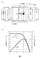
- FIG. 1 is a schematic diagram showing configurations of hybrid power supply system 10 (a) and hybrid power supply system 11 (b) based on the first embodiment of the present invention and its modification.
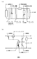
- FIG. 2 is a schematic diagram showing a configuration of hybrid power supply system 20 according to the second embodiment of the present invention.
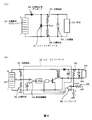
- FIG. 3 is the schematic (a) which shows the structure of the hybrid power supply system 30 based on Embodiment 3 of this invention, and the graph (b) which shows the electric power generation characteristic of a solar cell module.
- FIG. 4 is a graph for explaining the operation of the power supply system proposed in Patent Document 1 based on the current-voltage characteristics of the fuel cell and the secondary battery.
- FIG. 1 is a schematic diagram showing configurations of hybrid power supply system 10 (a) and hybrid power supply system 11 (b) based on the first embodiment of the present invention and its modification.
- FIG. 2 is a schematic diagram showing a configuration of hybrid power supply system 20 according to the second embodiment of the present invention.
- FIG. 3 is the schematic (a)
- FIG. 5 is a schematic diagram showing the configuration of the portable power supply device with battery charger 100 (a) and the current control circuit 107 (b) proposed in Patent Document 2.
- FIG. 6 is a schematic diagram showing a configuration of a power supply device using a solar cell proposed in Patent Document 3. As shown in FIG.
- the output voltage of the DC voltage converting means is set slightly higher than the voltage of the secondary battery.
- the DC voltage conversion means may control the input side voltage to the optimum operating voltage of the solar cell module or the fuel cell module or the vicinity thereof.
- the shunt circuit is constituted by a constant voltage diode, and the Zener voltage has such a magnitude that the secondary battery can be substantially fully charged. The voltage should not be large enough to cause an overcharged state of the secondary battery.
- the shunt circuit is constituted by a plurality of diodes connected in series, and the sum of the forward voltage drops of each diode makes the secondary battery substantially fully charged.
- the voltage be such that the voltage is large enough not to cause an overcharged state of the secondary battery.
- the shunt circuit is constituted by a shunt regulator circuit having a shunt path composed of transistors, and the shunt regulator circuit allows the voltage applied between the terminals of the secondary battery.
- the maximum value should be limited to a voltage that is large enough to make the secondary battery fully charged and does not cause an overcharged state of the secondary battery. .
- the maximum value of the voltage limited by the shunt regulator circuit is set by comparing the reference voltage obtained by dividing the voltage with a dividing resistor and the internal reference voltage of the shunt regulator circuit. It is good to be.
- the solar cell may be a dye-sensitized solar cell.
- FIG. 1A is a schematic diagram showing a configuration of a hybrid power supply system 10 based on the first embodiment.
- the hybrid power supply system 10 includes a solar cell module 1, a DC / DC converter 2, which is the DC voltage conversion means, a secondary battery 4, a resistor 5, and a constant voltage diode 6.
- the solar cell module 1 is a DC / DC converter.
- the load 3 and the secondary battery 4 are connected in parallel to the output side of the DC / DC converter 2.
- the electric power generated by the solar cell module 1 is converted into an appropriate voltage by the DC / DC converter 2 and then supplied to the load 3 and the secondary battery 4.
- the secondary battery 4 is charged and surplus generated power is stored in the secondary battery 4.
- the secondary battery 4 is discharged, and the solar battery module 1 and the secondary battery 4 drive the load 3.
- the output voltage of the DC / DC converter 2 is preferably set slightly higher than the voltage of the secondary battery 4. In such a case, loss when charging the secondary battery 4 can be minimized. Moreover, when discharging the secondary battery 4, both the solar cell module 1 and the secondary battery 4 can be used effectively. Since the hybrid power supply system 10 includes the DC / DC converter 2, such fine control is possible and high energy efficiency can be realized.
- the hybrid power supply system 10 has a constant voltage diode 6 connected in parallel with the secondary battery 4 as the shunt circuit on the output side of the DC / DC converter 2 as a feature thereof.
- the zener voltage of the constant voltage diode 6 is such a voltage that the secondary battery 4 can be substantially fully charged and does not cause an overcharged state of the secondary battery 4. .
- the hybrid power supply system 10 performs two different operations depending on the state of charge of the secondary battery 4. That is, if the secondary battery 4 does not reach a substantially fully charged state, surplus power is consumed by charging the secondary battery 4, and therefore the voltage between the terminals of the secondary battery 4 is sufficiently smaller than the fully charged voltage. Is maintained and does not exceed the zener voltage. At this time, only a slight reverse leakage current flows through the constant voltage diode 6, and most of the surplus power is used for charging the secondary battery 4.
- the secondary battery 4 when the secondary battery 4 reaches a substantially fully charged state, the surplus power is not consumed and accumulated by charging, so the voltage between the terminals of the secondary battery 4 starts to increase rapidly, and the Zener voltage Try to exceed. At this time, a Zener current immediately flows through the constant voltage diode 6 and the current flowing through the resistor 5 increases. As a result, the voltage drop in the resistor 5 increases, so that the voltage between the terminals of the secondary battery 4 is kept at the Zener voltage. Due to the voltage limiting action of the constant voltage diode 6, the charging of the secondary battery 4 automatically stops when the voltage between the terminals reaches the Zener voltage, and the secondary battery 4 is not overcharged.
- the solar cell of the solar cell module 1 is preferably a dye-sensitized solar cell. As described above, since the dye-sensitized solar cell is likely to be thermally deteriorated and it is necessary to suppress the temperature rise, the present invention can be suitably applied. Further, in the present embodiment, an example in which the power source is a solar cell module has been described.
- the present invention is also applied to a passive fuel cell having no means for controlling the supply of fuel. It can be suitably applied.
- the fuel cell is not limited, but is particularly preferably a direct methanol fuel cell suitable as a power source for portable devices.
- the secondary battery may be a lithium ion battery. Lithium ion batteries are most preferred as secondary batteries used in this system because they have a higher output density and less loss due to the difference between the charge voltage and discharge voltage compared to nickel hydride batteries and nickel cadmium batteries.
- the full charge voltage of a lithium ion battery is approximately 4.0 to 4.2 V, although it varies depending on the composition of the electrode.
- the overcharge voltage is a level obtained by adding 0.1 to 0.2 V to the full charge voltage.
- the Zener voltage of the constant voltage diode 6 is preferably about 4.1 to 4.2 V.
- the Zener voltage is 4.2 V
- the lithium ion battery can be charged to a fully charged state.
- the zener voltage is 4.1 V or more and less than 4.2 V
- the lithium ion battery cannot be charged to a fully charged state in a strict sense, but accumulates almost the same power as the fully charged state, and the hybrid
- the performance required for the power supply system 10 can be realized in a substantially full charge state that can be realized in the same manner as the full charge state.
- FIG. 1B is a schematic diagram showing a configuration of a hybrid power supply system 11 based on a modification of the first embodiment.
- This example corresponds to claim 5 and is an example in which a plurality of diodes 7 connected in series in the forward direction are provided in place of the constant voltage diode 6 as the shunt circuit.
- the sum of the forward voltage drops of the respective diodes is such a voltage that the secondary battery 4 can be substantially fully charged and does not cause an overcharged state of the secondary battery 4. It is.
- the hybrid power supply system 11 when the secondary battery 4 is in a fully charged state and the output voltage of the DC / DC converter 2 tries to exceed the voltage causing overcharge, a forward current immediately flows through the diode array 7, and the hybrid power supply The same effect as the system 10 can be obtained.
- FIG. 2 is a schematic diagram showing a configuration of hybrid power supply system 20 based on the second embodiment.
- the hybrid power supply system 20 includes a solar cell module 1, a DC / DC converter 2 that is the DC voltage conversion means, a secondary battery 4, a resistor 5, divided resistors 21 and 22, and a shunt regulator circuit 23.
- a shunt regulator circuit 23 is used instead of the constant voltage diode 6 as the shunt circuit, and divided resistors 21 and 22 are provided. Since other than these are the same as the hybrid power supply system 10, differences will be mainly described.
- the shunt regulator circuit 23 includes a shunt path composed of a transistor 24 connected in parallel to the secondary battery 4, a reference voltage generator 25 that generates a reference voltage Vs, an error amplifier 26, and the like. It is constituted by.
- the dividing resistors 21 and 22 divide the voltage between the terminals of the secondary battery 4 and give a reference voltage Vref1 to be applied to the reference voltage terminal REF.
- Vref1 is smaller than Vs
- the difference is amplified by the error amplifier 26 and applied to the base terminal of the transistor 24, so that the transistor 24 is completely turned off.
- Vref1 is larger than Vs, the difference is amplified by the error amplifier 26 and applied to the base terminal of the transistor 24.
- Vmax can make the secondary battery 4 substantially fully charged, and the secondary battery 4 is overcharged. It is set to a size that will not be allowed.
- the hybrid power supply system 20 performs two different operations depending on the state of charge of the secondary battery 4. That is, if the secondary battery 4 does not reach a substantially fully charged state, surplus power is consumed by charging the secondary battery 4, and therefore the voltage between the terminals of the secondary battery 4 is sufficiently smaller than the fully charged voltage. Is maintained and never exceeds Vmax. At this time, Vref1 ⁇ Vs Therefore, the transistor 24 is in a completely off state.
- Vref1 Vs Is kept equal to Vmax, that is, Vmax. Due to the voltage limiting action by the shunt regulator circuit 23, the charging of the secondary battery 4 is automatically stopped when the voltage between the terminals reaches Vmax, and the secondary battery 4 is not overcharged. In addition, surplus power is shunted (shunted) through the transistor 24, converted into heat by the resistance of the transistor 24, and discarded.
- Vmax is preferably about 4.2 V.
- the transistor 24 may be a field effect transistor.
- the shunt regulator circuit 23 may be constituted by discrete components, but it is convenient to use a commercially available shunt regulator IC (integrated circuit) element. Alternatively, the resistor connected in series and the transistor 24 may be connected in parallel with the secondary battery 4 so that a part of the surplus power is changed to heat by the resistor. This is desirable because heat generation in the transistor 24 is reduced.
- the hybrid power supply system 20 can be configured as in the first embodiment.
- the system 20 using the shunt regulator circuit 23 is the most practical system in which Vmax can be set accurately and energy energy loss is small.
- FIG. 3A is a schematic diagram showing a configuration of a hybrid power supply system 30 based on the third embodiment of the present invention.
- the hybrid power supply system 30 includes a solar cell module 1, a DC / DC converter 31 that is the DC voltage conversion means, a secondary battery 4, divided resistors 21 and 22, and a shunt regulator circuit 23.
- a DC / DC converter 31 is used instead of the DC / DC converter 2 used in the hybrid power supply systems 10 and 20, and the resistor 5 is omitted. Since other than these are the same as the hybrid power supply system 20, differences will be mainly described.
- the output voltage of the DC / DC converter 2 is set slightly higher than the voltage of the secondary battery 4. In this case, the voltage on the input side of the DC / DC converter 2 can be controlled to some extent by limiting the output current, but cannot usually be determined accurately.
- the output voltage is kept constant by the DC / DC converter 2, but the input side voltage is indefinite.
- the DC / DC converter 31 used in the hybrid power supply system 30 has a function of controlling the input side voltage to which the solar cell module 1 is connected to the optimum operating voltage of the solar cell module 1 or in the vicinity thereof. .
- the DC / DC converter 31 has, for example, a dividing resistor that divides the output voltage of the solar cell module 1 on the input side and gives a reference voltage, like the DC / DC converter 301 shown in FIG.
- the DC / DC converter 31 Provided to amplify the difference between the reference voltage and the built-in reference voltage by an error amplifier, and control the operation of the DC / DC converter based on the magnitude to maintain the input side voltage at a predetermined level Has been.
- LT3652 trade name; manufactured by Linear Technology Corporation
- the resistor 5 provided in the hybrid power supply systems 10 and 20 can be omitted.
- the output side voltage of the DC / DC converter 31 is the voltage of the secondary battery 4. It is automatically adjusted by the open circuit voltage, the internal resistance of the secondary battery 4 and the output impedance of the DC / DC converter 31.
- the transistor 24 is immediately turned on, and the output side voltage of the DC / DC converter 31 is kept equal to Vmax. The secondary battery 4 is not overcharged by the voltage limiting action of the shunt regulator circuit 23.
- FIG. 3B is a graph showing an example of the power generation characteristics of the solar cell module 1. Since the solar cell does not have a function of storing energy, in order not to waste the irradiated light, it is preferable to continue to generate power at as high an output as possible regardless of the required power of the load 3. Therefore, in the solar cell module 1 having the power generation characteristics shown in FIG. 3B, it is preferable to operate so that the power generation voltage is always constant at about 4.1V.
- the solar cell module 1 is irradiated. Light can be converted to electric power with maximum efficiency.
- this invention was demonstrated based on embodiment, it cannot be overemphasized that the above-mentioned example can be suitably changed in the range which does not deviate from the main point of invention based on the technical idea of this invention.
- SYMBOLS 1 Solar cell module, 2 ... DC / DC converter, 3 ... Load, 4 ... Secondary battery, 5 ... Resistance, 6 ... Constant voltage diode, 7 ... Several diodes connected in series 10, 11, DESCRIPTION OF SYMBOLS 20 ... Hybrid power supply system, 21, 22 ... Dividing resistor, 23 ... Shunt regulator circuit, 24 ... Transistor, 25 ... Reference voltage generation part, 26 ... Error amplifier, 30 ... Hybrid power supply system, 31 ... DC / DC converter, 100 ... Portable power supply device with battery charger, 101 ... solar cell, 102 ... DC / DC converter (diode for backflow prevention), 103 ...
- split resistor 304 ... error amplifier, 305 ... comparator, A ... shunt regulator Anode terminal of circuit 23, K ... cathode terminal of shunt regulator circuit 23, REF ... reference voltage terminal of shunt regulator circuit 23, Vref1, Vref2 ... reference voltage, X ... intersection
Landscapes
- Chemical & Material Sciences (AREA)
- Chemical Kinetics & Catalysis (AREA)
- Electrochemistry (AREA)
- General Chemical & Material Sciences (AREA)
- Engineering & Computer Science (AREA)
- Life Sciences & Earth Sciences (AREA)
- Sustainable Development (AREA)
- Sustainable Energy (AREA)
- Power Engineering (AREA)
- Charge And Discharge Circuits For Batteries Or The Like (AREA)
- Secondary Cells (AREA)
- Fuel Cell (AREA)
- Photovoltaic Devices (AREA)
- Hybrid Cells (AREA)
Abstract
Description
太陽電池を用いて電子機器を安定に駆動する電源を構成するシステムとして、太陽電池と二次電池とを組み合わせ、二次電池を電力バッファとして用いるハイブリッド電源システムが知られている。このシステムでは、太陽電池の発電量が電子機器を駆動する電力を上回っている場合には、二次電池を充電して、太陽電池が生み出した余剰の電力を二次電池に蓄える。一方、太陽電池の発電量が電子機器を駆動する電力を下回っている場合には、二次電池を放電させ、太陽電池と二次電池とで電子機器を駆動する。
ハイブリッド電源システムを構成することによって、太陽電池は電子機器の最大消費電力に対応する必要性がなくなり、平均として電子機器の消費電力を供給すればよいことになる。この結果、太陽電池のサイズを小型化することができる。太陽電池と二次電池とのハイブリッド電源システムは、電力の安定供給と太陽電池の小型化の両方を実現でき、小型化およびポータブル化を目指す電子機器にとって非常に効果的なシステムである。
一方、パーソナルコンピュータや携帯電話などの携帯型電子機器では、その高機能化および多機能化にともない、消費電力が増加する傾向にあり、この傾向に対応できる、次世代の携帯型電子機器用電源として、燃料電池が期待されている。燃料電池では、負極(アノード)側に燃料が供給されて燃料が酸化され、正極(カソ−ド)側に空気または酸素が供給されて酸素が還元され、燃料電池全体では燃料と酸素との酸化還元反応が起こる。このとき、燃料がもつ化学エネルギーが、効率よく電気エネルギーに変換されて取り出される。燃料電池には、故障しない限り、燃料を補給することで、電源として使い続けることができる特徴がある。
様々な種類の燃料電池が提案されているが、水素イオン伝導性高分子膜を電解質として用いる高分子電解質形燃料電池(PEFC)は、電解質が固体で飛散するおそれがないことや、他の形式の燃料電池に比べて低い温度、例えば30℃~130℃程度の温度で動作させることができ、起動時間が短いことなどから、携帯型電源として好適である。
燃料電池の燃料としては、水素やメタノールなど、種々の可燃性物質を用いることができる。しかし、水素などの気体燃料は、貯蔵用の高圧容器または水素吸蔵合金などが必要になるため、小型軽量化には適さない。一方、メタノールなどの液体燃料は、貯蔵しやすいという利点があるが、改質器によって液体燃料から水素を取り出す方式の燃料電池は、構成が複雑になるので、小型化には適さない。これらに対し、メタノールを改質することなく、直接アノードに供給して反応させるダイレクトメタノール形燃料電池(DMFC)には、燃料を貯蔵しやすく、かつ、構成が簡素で、小型化が容易であるという特徴がある。従来、DMFCは、多くがPEFCと組み合わされて、PEFCの1種として研究されてきており、携帯型電子機器用電源として最も高く期待されている。
しかしながら、DMFCの出力密度は比較的小さいので、携帯型電子機器を駆動する電力を燃料電池単独で発生させようとすると、燃料電池のサイズが大きくなりすぎることが懸念される。従って、DMFCなどの燃料電池においても、リチウムイオン電池など、出力密度の大きい二次電池とハイブリッド電源システムを構成することが効果的である。
そこで、後述の特許文献1では、燃料電池と二次電池とが負荷に対して並列に接続され、燃料電池および二次電池の少なくとも一方が負荷に対して電力を供給するハイブリッド電源システムが提案されている。図4は、燃料電池および二次電池の電流−電圧特性に基づいて、上記電源システムの動作を説明するためのグラフである。なお、図4に示されている燃料電池および二次電池の電圧は、単電池のものではなく、それぞれ複数個の電池を直列に接続した電池スタックの電圧である。また、二次電池の電流Irは放電方向を正(Ir>0)にとっているので、充電が行われる場合には電流Irは負(Ir<0)である。
図4に示されているように、燃料電池の電流−電圧曲線はシグモイド状の形状を有し、発電電流が増加するにつれて発電電圧が比較的大きく低下する。これは、燃料電池では、発電電流の増加につれて活性化分極、抵抗分極、および拡散分極が順次顕著に現れてくるからである。一方、リチウムイオン電池などの二次電池の電流−電圧曲線は直線性が高く、放電電流が増加すると抵抗分極などによって徐々に放電電圧が低下するものの、その傾きは比較的小さく、内部抵抗は小さい。充電時も同様で、充電電流が増加すると徐々に充電電圧が上昇するものの、その傾きは小さい。二次電池の開放電圧Vr0は、二次電池がどの程度充電されているかという充電状態によって変化する。
この電源システムでは、外部負荷がない場合、燃料電池によって生み出される電力はすべて、二次電池の充電に用いられる。このときの電圧をVc、燃料電池の発電電流の大きさをIfc、二次電池の充電電流の大きさを−Ircとすると、
Ifc=−Irc
の関係が成り立つから、電圧Vcは、図4においてこの関係を満たす電圧(>Vr0)として定まる。外部負荷がゼロではないが小さい場合には、燃料電池によって生み出される電力は、一部が負荷の駆動に用いられ、余剰電力が二次電池の充電に用いられる。このときの電圧は、Vcより小さく、Vr0より大きい。
負荷がより大きく、電圧がVr0より小さい場合には、二次電池の放電が起こり、負荷は燃料電池と二次電池とによって駆動される。この際、各電池がそれぞれ効果的に機能するには、図4に示すように、2つの電池の電流−電圧曲線が適当な領域で交わる必要がある。このようであると、負荷が比較的小さく、負荷を駆動する電圧V1が交点Xの電圧Vxよりも大きい場合には、燃料電池および二次電池から供給される電流は、図4に示すように、それぞれIf1およびIr1と求まる。If1>Ir1であるから、電力は主として燃料電池から供給されている。これに対して、負荷が大きく、駆動電圧V2がVxよりも小さい場合には、燃料電池および二次電池から供給される電流は、図4に示すように、それぞれIf2およびIr2となる。If2<Ir2であるから、この場合には、二次電池から供給される電力が、燃料電池から供給される電力を上回っている。
負荷が増加して駆動電圧がVxを間に挟んでV1からV2に減少する間に、燃料電池からの発電電流がIf1からIf2に増加するのにすぎないのに対して、二次電池からの放電電流はIr1からIr2に大きく増加しており、この間に増加する電力消費の大部分が二次電池から供給されることがわかる。また、この電力消費の増加分を燃料電池のみで負担すると、図4からわかるように、燃料電池の発電電圧は、負荷を駆動できる最小電圧未満に低下する。上述したように、燃料電池のみで電源を構成する場合には、最小駆動電圧以上の発電電圧を維持できるように、燃料電池の大型化が必要である。また、出力密度に優れた二次電池を燃料電池と並列に接続してハイブリッド電源を構成した場合には、燃料電池を小型化し、ひいては電源システム全体を小型化することができる。
しかしながら、上記電源システムでは、燃料電池および二次電池の電流−電圧曲線が適当な領域で交わる必要があり、しかも、これらの電流−電圧特性によってシステム特性が完全に決定される。この例のように、太陽電池または燃料電池と二次電池とを並列に接続しただけの単純なシステムでは、太陽電池または燃料電池の特性と二次電池の特性とが互いに制約し合い、また、二次電池を充電するときの特性と放電させるときの特性とが互いに制約し合うので、エネルギー効率や安定性や利便性の向上に限界がある。例えば、エネルギー効率は、各電池の特性や二次電池の充電状態によって支配され、安定性は、各電池の特性の経年変化などによって大きく影響される。また、高効率充電や急速充電などの各種充電方式を使い分けることは不可能である。
また、ハイブリッド電源システムにおいて、二次電池の過充電の防止は非常に重要な課題である。例えば、二次電池としてリチウムイオン電池を用いた場合、過充電すると、発煙、発火、場合によっては爆発などの危険性が生じる。太陽電池は光が照射されると電力を発生してしまうので、二次電池の充電状態を常に検知し、満充電に達したところで充電を止める何らかの機構が必要である。また、燃料の供給を制御する手段をもたないパッシブ型の燃料電池でも常時発電が行われるので、同様の機構が必要である。
そこで、後述の特許文献2には、DC/DCコンバータ、電流制御回路、および過電流防止回路を備えたバッテリーチャージャー付きポータブル電源装置が提案されている。図5(a)は、この電源装置100の構成を示す概略図である。
図5(a)に示すように、電源装置100では、太陽光を受光し発電する太陽電池セル101は、逆流防止用ダイオード102を介して電気二重層コンデンサ103に接続されており、太陽電池セル101が発電した電力はいったんコンデンサ103に蓄えられる。コンデンサ103に蓄えられた電力は、DC/DCコンバータ105によって適当な電圧に変換された後、負荷104および二次電池106に供給される。
さらに電源装置100には、その特徴として、DC/DCコンバータ105と二次電池106および負荷104との間に、電流制御回路107が設けられており、電流制御回路107と二次電池106との間に、過電流防止回路108が設けられている。
図5(b)は、特許文献2に例示されている電流制御回路107の概略図である。電流制御回路107は、一般的なシリーズレギュレータの制御回路と同様に構成されている。すなわち、分割抵抗111および112は、出力電圧を分割して参照電圧Vref1を与える。定電圧ダイオード113は基準電圧を生成する。制御トランジスタ114とその負荷抵抗115は、基準電圧(厳密には、基準電圧と、制御トランジスタ114のベース−エミッタ間電圧との和)と参照電圧Vref1との差を増幅し、その大小に応じてパワートランジスタ116の動作を制御する。パワートランジスタ116は負荷104に直列に挿入されており、その出力電圧が一定になるように、導電性が制御トランジスタ114によって制御される。過電流防止回路108の具体的な構成は、特許文献2に示されていない。
電源装置100では、太陽電池セル101の発電電力が、負荷104を駆動する電力を上回っている場合には、余剰分の電力によって二次電池106が充電される。二次電池106が満充電状態に達すると、過電流防止回路108によって二次電池106への充電が停止される。従って、二次電池106が過充電されることがない。このとき、余剰電力は電気二重層コンデンサ103に蓄積されるので、コンデンサ103の電圧が上昇する。これによってDC/DCコンバータ105の出力電圧が上昇しても、負荷104に印加される電圧は電流制御回路107によって所定の電圧に制御されるので、負荷104に過大な電圧が印加されることはない。
この場合、太陽電池セル101が発電した余剰電力は行き場を失うので、余剰電力の蓄積によるコンデンサ103の電圧上昇が懸念される。特許文献2には、余剰電力は制御トランジスタ114およびその負荷抵抗115によって消費されるので、コンデンサ103の電圧上昇は抑えられると説明されている。
一方、後述の特許文献3には、いかなる天候の下でも太陽電池から得られる電力を最大限に利用できる電源装置として、7種の装置が示されている。図6は、そのうち、本発明と関係のある2種の電源装置の構成を示す概略図である。
図6(a)に示す電源装置200では、太陽電池モジュール201は、逆流防止用ダイオード202を介して負荷203および二次電池204に接続されている。この際、電源装置200の特徴として、逆流防止用ダイオード202の順方向電圧降下分の電圧と二次電池204の電圧との和が、太陽電池モジュール201の最適動作電圧とほぼ等しくなるように構成されている。電源装置200では、太陽電池モジュール201の発電電力が、負荷203を駆動する電力を上回っている場合には、余剰分の電力によって二次電池204が充電されるが、上記のように構成されているので、太陽電池モジュール201から得られる電力を最大限に利用することができる。
また、電源装置200の他の特徴として、負荷203および二次電池204と並列に、シャントレギュレータ207が接続されている。シャントレギュレータ207は、出力電圧を分割抵抗205および206によって分割することによって得られる参照電圧Vref1によって制御され、出力電圧の最大値を、二次電池204の過充電を引き起こす過充電電圧より小さい所定の電圧に抑えるように設定されている。
電源装置200では、二次電池204が満充電状態に達しておらず、二次電池204が余剰電力によって正常に充電されている間は、充電によって出力電圧が過充電電圧より小さい電圧に保たれるので、シャントレギュレータ207による電圧制限は行われない。一方、二次電池204が満充電状態に達すると、余剰電力が充電によって消費されず、蓄積されるので、出力電圧はすみやかに増加し始め、二次電池204の過充電電圧をこえようとする。このとき、直ちにシャントレギュレータ207による電圧制限作用が発揮され、余剰電力はシャントレギュレータ207を通じて分流(シャント)され、シャントレギュレータ207内の抵抗分によって熱に変えられて廃棄される。この結果、出力電圧は二次電池204の過充電電圧より小さい所定の電圧に保たれるので、二次電池204が過充電されることがない。
図6(b)に示す電源装置300では、太陽電池モジュール201が発電した電力は、DC/DCコンバータ301によって適当な電圧に変換された後に、負荷203および二次電池204に供給される。電源装置300では、その特徴として、DC/DCコンバータ301の入力側に、太陽電池モジュール201の出力電圧を分割して参照電圧Vref2を与える分割抵抗302および303が設けられ、参照電圧Vref2と内蔵基準電圧との差を誤差増幅器304によって増幅し、その大きさに基づいてDC/DCコンバータの動作を制御することにより、太陽電池モジュール201の出力電圧をその最適動作電圧に保つように構成されている。
また、DC/DCコンバータ301の出力側には、出力電圧を分割して参照電圧Vref1を与える分割抵抗205および206と、参照電圧Vref1と基準電圧とを比較して二次電池204の過充電を検知するコンパレータ305が設けられており、DC/DCコンバータ内には、コンパレータ305によって過充電が検知された場合にコンバータの動作を停止させるAND回路が設けられている。従って、DC/DCコンバータ301の出力電圧は、二次電池204の過充電を引き起こす電圧より小さい所定の電圧に保たれ、二次電池204が過充電されることがない。
従って、電源装置100では、二次電池106が満充電状態になると、太陽電池セル101が発電した余剰電力を取り出せなくなり、太陽電池セル101のエネルギー変換効率が実効的に低下する。この結果、太陽電池セル101の温度が高くなり過ぎるという問題が生じる。すなわち、太陽電池セル101によって吸収される光のエネルギーがWであり、電力への変換効率がη0であり、発電された電力がすべて取り出されるとすると、Wのうち、電力に変換されず、熱エネルギーとなり、太陽電池セル101の温度上昇を引き起こすエネルギーQ0は
Q0=(1−η0)W
である。一方、余剰電力が取り出されないことによって実効的な変換効率がη(<η0)に低下したとすると、熱エネルギーとなり、太陽電池セル101の温度上昇を引き起こすエネルギーQは
Q=(1−η)W
に変化する。
Q−Q0=(η0−η)W>0
であるから、変換効率が実効的に低下した分だけ、熱エネルギーとなり、太陽電池セル101の温度上昇を引き起こすエネルギーが増加し、太陽電池セル101の温度が高くなる。
特許文献3に提案されている電源装置300でも、太陽電池モジュール201の発電電力が負荷203を駆動する電力を上回っている場合に、コンパレータ305が二次電池204の過充電を検知すると、DC/DCコンバータ301の動作を停止させるので、太陽電池モジュール201の余剰電力を取り出せなくなり、同様の問題が生じる。
太陽電池の温度上昇は、色素増感太陽電池で特に問題になる。太陽電池では、発電に伴う劣化や光劣化や熱劣化など、様々な劣化原因が考えられるが、色素増感太陽電池では、温度上昇によって熱劣化が早く進行することが報告されている(特開2005−158621号公報、および、P.M.Sommeling,M.Spath,H.J.P.Smit,N.J.Bakker,J.M.Kroon,“Long−term stability testing of dye−sensitized solar cells”,Journal of Photochemistry and Photobiology.A.Chemistry,164(1−3),(2004),137−144参照。)。従って、色素増感太陽電池では温度上昇を抑える必要がある。
燃料電池においても、余剰電力が取り出されない状況は非常に大きな問題となる。余剰電力が取り出されないと、燃料電池の発電電流が低下し、これに伴って燃料電池のカソードの電位が上昇する。この結果、カソード表面における酸化還元平衡が酸化側にシフトし、電極触媒材料である白金などの金属がイオンとして溶出する可能性が生じる。この状況が長く続くと、カソード触媒が次第に痩せ細り、電極から脱落することが懸念される。また、溶出したイオンが電解質膜内などで再析出して、電解質膜を破壊してしまう危険性も懸念される。
一方、特許文献3に提案されている電源装置200では、太陽電池モジュール201の発電電力が負荷203を駆動する電力を上回っている場合に、二次電池204が満充電状態に達すると、余剰電力はシャントレギュレータ207を通じて分流(シャント)され、熱に変えられて廃棄される。従って、二次電池204が過充電されることがなく、しかも、余剰電力が取り出せなくなって、太陽電池モジュール201の変換効率が実効的に低下して、太陽電池モジュール201の温度上昇を招くこともない。
しかしながら、電源装置200は、DC/DCコンバータなどの直流電圧変換手段を備えていないので、エネルギー効率や安定性や利便性の向上に限界がある。例えば、二次電池204の充電量が少なく、太陽電池モジュール201の最適動作電圧と二次電池204の電圧との差が大きいときには、二次電池204の充電過程で損失になる電力が大きくなり、システムのエネルギー効率は低下する。また、曇天などの稼働条件の変化などで太陽電池モジュール201の出力電圧が二次電池204の電圧に比べて低くなると、負荷203を駆動する電力はもっぱら二次電池204から供給され、太陽電池モジュール201が発電した電力が全く利用されない状態も起こり得る。また、経年変化などによって太陽電池モジュール201の最適動作電圧や二次電池204の特性が変化すると、当初の性能が著しく損なわれる可能性が高い。
以上のように、太陽電池または燃料電池と二次電池とを組み合わせ、二次電池を電力バッファとして用いるハイブリッド電源システムであって、二次電池の充電状態の変化や稼働条件の変化や部材の経年変化があっても高いエネルギー効率を維持することができ、しかも、二次電池の過充電を防止し、かつ、取り出せない余剰電力の発生による太陽電池の熱劣化または燃料電池におけるカソード触媒の溶出を抑えることのできるハイブリッド電源システムは未だ提案されていない。
本発明は、上述したような問題点を解決するためになされたものであって、その目的は、太陽電池または燃料電池と二次電池とを組み合わせ、二次電池を電力バッファとして用いるハイブリッド電源システムであって、二次電池の充電状態の変化や稼働条件の変化や部材の経年変化があっても高いエネルギー効率を維持することができ、しかも、二次電池の過充電を防止し、かつ、取り出せない余剰電力の発生による太陽電池の熱劣化または燃料電池におけるカソード触媒の溶出を抑えることのできるハイブリッド電源システムを提供することにある。
即ち、本発明は、
太陽電池モジュール又は燃料電池モジュールと、
前記太陽電池モジュール又は前記燃料電池モジュールが入力側に接続され、負荷及び二次電池が出力側に接続され、前記太陽電池モジュール又は前記燃料電池モジュールが発電した発電電力を適当な電圧に変換した後に、前記負荷及び前記二次電池に供給する直流電圧変換手段と、
前記直流電圧変換手段の出力側に前記負荷と並列に接続される前記二次電池と、
前記直流電圧変換手段の出力側に前記二次電池と並列に接続されており、前記二次電池が実質的に満充電の状態にあるとき、前記発電電力のうち、前記負荷で消費されない余剰電力を実質的にすべて熱に変えて廃棄する分流(シャント)回路と
を有する、ハイブリッド電源システムに係わる。
ここで、「前記二次電池が実質的に満充電の状態にある」の「実質的に満充電の状態」とは、厳密な意味での満充電状態に加えて、満充電状態とほぼ同じ電力を蓄積し、前記ハイブリッド電源システムに要求される性能を満充電状態と同様に実現できる充電状態、すなわち、システム性能上、満充電状態とほぼ同等とみなされる充電状態をも含むという意味である。また、「余剰電力を実質的にすべて」の「実質的にすべて」とは、「短絡防止用の抵抗、および電圧検出用の抵抗や制御回路など、回路を正常に働かせる上で必要な回路で必然的に消費される電力を除くすべて」という意味である。
本発明のハイブリッド電源システムでは、前記太陽電池モジュール又は前記燃料電池モジュールが発電した発電電力を、並列に接続された前記負荷及び前記二次電池に供給する。そして、発電電力が前記負荷を駆動する電力を上回っている場合には、前記二次電池を充電して、余剰の電力を前記二次電池に蓄える。一方、発電電力が前記負荷を駆動する電力を下回っている場合には、前記二次電池を放電させ、前記太陽電池モジュール又は前記燃料電池モジュールと前記二次電池とで前記負荷を駆動する。この結果、前記太陽電池モジュール又は前記燃料電池モジュールは、前記負荷の最大消費電力に対応する必要性がなくなり、平均として前記負荷の消費電力を供給すればよいことになるので、前記太陽電池モジュール又は前記燃料電池モジュールのサイズを小型化することができる。
この際、本発明のハイブリッド電源システムは、その特徴として、前記直流電圧変換手段を有し、発電電力を適当な電圧に変換した後に前記負荷及び前記二次電池に供給する。この結果、前記二次電池を充電する際の損失を最小限に抑えることができる。また、前記二次電池を放電させる場合には、前記太陽電池モジュール又は前記燃料電池モジュールと前記二次電池との両方を有効に利用することができる。また、晴天や曇天などの稼働条件が変化しても、あるいは経年変化などによって各部材の特性が変化しても、高いエネルギー効率を維持できる。
さらに、本発明のハイブリッド電源システムは、その特徴として、前記直流電圧変換手段の出力側に前記二次電池と並列に接続され、前記二次電池が満充電の状態にあるとき、前記発電電力のうち、前記負荷で消費されない余剰電力を実質的にすべて熱に変えて廃棄する前記分流(シャント)回路を有する。従って、前記二次電池が過充電されることがない。しかも、前記太陽電池モジュール又は前記燃料電池モジュールから余剰電力を取り出せなくなることもない。この結果、前記太陽電池モジュールを用いた場合に、電力への変換効率が実効的に低下して温度上昇を招き、前記太陽電池モジュールの熱劣化を早めることがない。また、前記燃料電池を用いた場合に、前記燃料電池のカソード電位が上昇してカソード触媒の溶出による劣化を早めることがない。
図2は、本発明の実施の形態2に基づくハイブリッド電源システム20の構成を示す概略図である。
図3は、本発明の実施の形態3に基づくハイブリッド電源システム30の構成を示す概略図(a)、および太陽電池モジュールの発電特性を示すグラフ(b)である。
図4は、燃料電池および二次電池の電流−電圧特性に基づいて、特許文献1に提案されている電源システムの動作を説明するためのグラフである。
図5は、特許文献2に提案されているバッテリーチャージャー付きポータブル電源装置100(a)および電流制御回路107(b)の構成を示す概略図である。
図6は、特許文献3に提案されている太陽電池を用いた電源装置の構成を示す概略図である。
或いは、前記直流電圧変換手段によってその入力側電圧が前記太陽電池モジュール又は前記燃料電池モジュールの最適動作電圧又はその近傍に制御されるのがよい。
また、前記分流(シャント)回路が、定電圧ダイオードによって構成されており、そのツェナー電圧が、前記二次電池を実質的に満充電の状態にすることができる大きさであり、かつ、前記二次電池の過充電状態を生じさせない大きさの電圧であるのがよい。
或いは、前記分流(シャント)回路が、直列に接続された複数個のダイオードによって構成されており、各ダイオードの順方向電圧降下の合計が、前記二次電池を実質的に満充電の状態にすることができる大きさであり、かつ、前記二次電池の過充電状態を生じさせない大きさの電圧であるのがよい。
或いは、また、前記分流(シャント)回路が、トランジスタからなる分流(シャント)路を有するシャントレギュレータ回路によって構成されており、このシャントレギュレータ回路によって、前記二次電池の端子間に印加される電圧の最大値が、前記二次電池を実質的に満充電の状態にすることができる大きさであり、かつ、前記二次電池の過充電状態を生じさせない大きさの電圧に制限されるのがよい。
この際、前記シャントレギュレータ回路によって制限される前記電圧の最大値が、前記電圧を分割抵抗で分割して得られた参照電圧と、前記シャントレギュレータ回路が有する内部基準電圧との比較によって設定されているのがよい。
また、前記太陽電池が色素増感型太陽電池であるのがよい。
また、前記燃料電池がダイレクトメタノール形燃料電池であるのがよい。
また、前記二次電池がリチウムイオン電池であるのがよい。
次に、本発明の好ましい実施の形態を図面参照下に具体的かつ詳細に説明する。
[実施の形態1]
実施の形態1では、主として、請求項1、2、4および5に記載したハイブリッド電源システムの例について説明する。
図1(a)は、実施の形態1に基づくハイブリッド電源システム10の構成を示す概略図である。ハイブリッド電源システム10は、太陽電池モジュール1、前記直流電圧変換手段であるDC/DCコンバータ2、二次電池4、抵抗5、および定電圧ダイオード6で構成され、太陽電池モジュール1がDC/DCコンバータ2の入力側に接続され、負荷3および二次電池4が並列に、DC/DCコンバータ2の出力側に接続されている。
ハイブリッド電源システム10では、太陽電池モジュール1が発電した電力を、DC/DCコンバータ2によって適当な電圧に変換した後に、負荷3および二次電池4に供給する。そして、発電電力が負荷3を駆動する電力を上回っている場合には、二次電池4を充電して、余剰の発電電力を二次電池4に蓄える。一方、発電電力が負荷3を駆動する電力を下回っている場合には、二次電池4を放電させ、太陽電池モジュール1と二次電池4とで負荷3を駆動する。この結果、太陽電池モジュール1は負荷3の最大消費電力に対応する必要性がなくなり、平均として負荷3の消費電力を供給すればよいことになるので、太陽電池モジュール1のサイズを小型化することができる。
この際、DC/DCコンバータ2の出力電圧は、二次電池4の電圧よりわずかに高く設定されているのがよい。このようであると、二次電池4を充電する際の損失を最小限に抑えることができる。また、二次電池4を放電させる場合には、太陽電池モジュール1と二次電池4との両方を有効に利用することができる。ハイブリッド電源システム10では、DC/DCコンバータ2を有するので、このような細やかな制御が可能であり、高いエネルギー効率を実現することができる。また、晴天や曇天などの稼働条件が変化しても、あるいは経年変化などによって太陽電池モジュール1や二次電池4の特性が変化しても、上記の条件を満たすことができ、高いエネルギー効率を維持できる。
さらに、ハイブリッド電源システム10は、その特徴として、DC/DCコンバータ2の出力側に、前記分流(シャント)回路として、二次電池4と並列に接続された定電圧ダイオード6を有する。定電圧ダイオード6のツェナー電圧は、二次電池4を実質的に満充電の状態にすることができる大きさであり、かつ、二次電池4の過充電状態を生じさせない大きさの電圧である。
この結果、太陽電池モジュール1の発電電力が負荷3を駆動する電力を上回っている場合、ハイブリッド電源システム10は、二次電池4の充電状態に応じて2通りの異なる動作を行う。
すなわち、二次電池4が実質的な満充電状態に達していなければ、余剰電力は二次電池4の充電によって消費されるので、二次電池4の端子間の電圧は満充電電圧より十分小さく保たれ、ツェナー電圧をこえることはない。このとき、定電圧ダイオード6にはわずかな逆方向リーク電流が流れるだけであり、余剰電力は大半が二次電池4の充電に用いられる。
一方、二次電池4が実質的に満充電の状態に達すると、余剰電力が充電によって消費されず、蓄積されるので、二次電池4の端子間の電圧はすみやかに増加し始め、ツェナー電圧をこえようとする。このとき、直ちに定電圧ダイオード6を通じてツェナー電流が流れ、抵抗5を流れる電流が増加する。これにより抵抗5における電圧降下が増加するので、二次電池4の端子間の電圧はツェナー電圧に保たれる。この定電圧ダイオード6による電圧制限作用によって、二次電池4への充電は、端子間の電圧がツェナー電圧に達したところで自動的に停止し、二次電池4が過充電されることがない。しかも、余剰電力は定電圧ダイオード6を通じて分流(シャント)され、定電圧ダイオード6が有する抵抗分によって熱に変えられて廃棄される。従って、太陽電池モジュール1から余剰電力が取り出せなくなり、この結果、太陽電池の変換効率が実効的に低下して温度上昇を招き、太陽電池モジュール1の熱劣化を早めることも起こらない。
太陽電池モジュール1の太陽電池が、色素増感型太陽電池であるのがよい。既述したように、色素増感型太陽電池は熱劣化が起こりやすく、温度上昇を抑える必要があるので、本発明を好適に適用することができる。また、本実施の形態では、電力源が太陽電池モジュールである例を示したが、既述したように、燃料の供給を制御する手段をもたないパッシブ型の燃料電池にも、本発明を好適に適用することができる。燃料電池は限定されるものではないが、携帯機器用電源として好適なダイレクトメタノール形燃料電池であるのが特によい。
また、前記二次電池がリチウムイオン電池であるのがよい。リチウムイオン電池は、ニッケル水素電池やニッケルカドミウム電池などに比べて、出力密度が大きく、充電電圧と放電電圧との差による損失が少ないことから、本システムに用いられる二次電池として最も好ましい。リチウムイオン電池の満充電電圧は、その電極の組成によっても異なるが、およそ4.0~4.2V程度である。また、過充電電圧は、満充電電圧に0.1~0.2Vを加算した程度である。前記二次電池として満充電電圧が4.2V、過充電電圧が4.4Vのリチウムイオン電池を用いる場合、定電圧ダイオード6のツェナー電圧は4.1~4.2V程度とするのがよい。ツェナー電圧が4.2Vである場合には、リチウムイオン電池を満充電状態にまで充電することができる。ツェナー電圧が4.1V以上、4.2V未満である場合には、リチウムイオン電池を厳密な意味での満充電状態に充電することはできないが、満充電状態とほぼ同じ電力を蓄積し、ハイブリッド電源システム10に要求される性能を満充電状態と同様に実現できる、実質的な満充電状態に充電することができる。これらは定電圧ダイオード6の作製精度や要求されるシステム性能等に応じて適宜選択するのがよい。また、DC/DCコンバータ2の出力電圧を、リチウムイオン電池の開放電圧に、電池の内部抵抗Rによる電圧降下分ΔV(=IR;ただし、Iは電池内を流れる充電または放電電流)を加算(充電時)または減算(放電時)した程度の大きさにするのがよい。この場合、ハイブリッド電源システム10を最もエネルギー効率よく動作させることができる。
図1(b)は、実施の形態1の変形例に基づくハイブリッド電源システム11の構成を示す概略図である。この例は請求項5に対応しており、前記分流(シャント)回路として、定電圧ダイオード6の代わりに、順方向に直列に接続された複数個のダイオード7が設けられている例である。各ダイオードの順方向電圧降下の合計は、二次電池4を実質的に満充電の状態にすることができる大きさであり、かつ、二次電池4の過充電状態を生じさせない大きさの電圧である。ハイブリッド電源システム11では、二次電池4が満充電状態になり、DC/DCコンバータ2の出力電圧が過充電を引き起こす電圧をこえようとすると、直ちにダイオード列7を通じて順方向電流が流れ、ハイブリッド電源システム10と同様の効果が得られる。
[実施の形態2]
実施の形態2では、主として、請求項6および7に記載したハイブリッド電源システムの例について説明する。
図2は、実施の形態2に基づくハイブリッド電源システム20の構成を示す概略図である。ハイブリッド電源システム20は、太陽電池モジュール1、前記直流電圧変換手段であるDC/DCコンバータ2、二次電池4、抵抗5、分割抵抗21および22、およびシャントレギュレータ回路23によって構成されている。ハイブリッド電源システム20では、前記分流(シャント)回路として、定電圧ダイオード6の代わりにシャントレギュレータ回路23が用いられており、分割抵抗21および22が設けられている。これら以外はハイブリッド電源システム10と同様であるので、主として相違点について説明する。
シャントレギュレータ回路23は、拡大図に示すように、二次電池4に並列に接続されたトランジスタ24からなる分流(シャント)路、基準電圧Vsを発生する基準電圧発生部25、および誤差増幅器26などによって構成されている。分割抵抗21および22は二次電池4の端子間の電圧を分割し、参照電圧端子REFに印加する参照電圧Vref1を与える。
Vref1がVsより小さい場合、その差が誤差増幅器26によって増幅され、トランジスタ24のベース端子に印加されるので、トランジスタ24は完全なオフ状態になる。一方、Vref1がVsより大きい場合、その差が誤差増幅器26によって増幅され、トランジスタ24のベース端子に印加されるので、トランジスタ24はオン状態になり、トランジスタ24からなる分流(シャント)路を電流が流れるので、抵抗5を流れる電流が増加する。これにより抵抗5における電圧降下が大きくなり、シャントレギュレータ回路23のアノード端子A−カソード端子K間の電圧は、
Vref1=Vs
の関係が満たされる大きさまで低下する。この電圧をVmaxとすると、分割抵抗21および22の抵抗値をそれぞれR21およびR22として、Vmaxは下記の式
Vmax=(R21/R22+1)Vs
で与えられる。ハイブリッド電源システム20では、R21およびR22を適切に選択することによって、Vmaxが、二次電池4を実質的に満充電の状態にすることができ、かつ、二次電池4の過充電状態を生じさせない大きさに設定されている。
この結果、太陽電池モジュール1の発電電力が負荷3を駆動する電力を上回っている場合、ハイブリッド電源システム20は、二次電池4の充電状態に応じて2通りの異なる動作を行う。
すなわち、二次電池4が実質的な満充電状態に達していなければ、余剰電力は二次電池4の充電によって消費されるので、二次電池4の端子間の電圧は満充電電圧より十分小さく保たれ、Vmax以上になることはない。このとき、
Vref1<Vs
であるので、トランジスタ24は完全なオフ状態にある。従って、トランジスタ24からなる分流(シャント)路を流れる電流は極めてわずかであり、余剰電力はほとんど全てが二次電池4の充電に用いられる。
一方、二次電池4が実質的に満充電の状態に達すると、余剰電力が充電によって消費されず、蓄積されるので、二次電池4の端子間の電圧はすみやかに増加し始め、Vmaxをこえて行こうとする。このとき、
Vref1>Vs
となるので、直ちにトランジスタ24はオン状態になり、トランジスタ24を通じて電流が流れ、抵抗5を流れる電流が増加する。これにより抵抗5における電圧降下が増加するので、シャントレギュレータ回路23のアノード端子A−カソード端子K間の電圧は、
Vref1=Vs
の関係が満たされる大きさ、すなわちVmaxに等しく保たれる。このシャントレギュレータ回路23による電圧制限作用によって、二次電池4への充電は、端子間の電圧がVmaxに達したところで自動的に停止し、二次電池4が過充電されることがない。しかも、余剰電力はトランジスタ24を通じて分流(シャント)され、トランジスタ24が有する抵抗分によって熱に変えられて廃棄される。従って、太陽電池モジュール1から余剰電力が取り出せなくなり、この結果、太陽電池の変換効率が実効的に低下して温度上昇を招き、太陽電池モジュール1の熱劣化を早めることも起こらない。
前記二次電池として満充電電圧が4.2V、過充電電圧が4.4Vのリチウムイオン電池を用いる場合、Vmaxは4.2V程度とするのがよい。これによって、リチウムイオン電池を満充電状態にまで充電することができ、最良のシステム性能を実現することができる。
図2では、トランジスタ24がバイポーラトランジスタである例を示したが、トランジスタ24が電界効果トランジスタであってもよい。シャントレギュレータ回路23はディスクリート部品で構成されていてもよいが、市販のシャントレギュレータIC(集積回路)素子を用いるのが簡便である。また、直列に接続された抵抗体とトランジスタ24とを二次電池4と並列に接続し、余剰電力の一部が抵抗体で熱に変わるようにしてもよい。このようにすると、トランジスタ24における発熱が小さくなるので望ましい。
上記のように、シャントレギュレータ回路23を用いることによって、実施の形態1と同様に、ハイブリッド電源システム20を構成することが可能である。このシャントレギュレータ回路23を用いたシステム20は、Vmaxを正確に設定することができ、エネルギーエネルギー損失が少ないなど、最も実用性の高いシステムである。図1(a)に示した定電圧ダイオード6を用いるシステム10は、回路的には簡便であるが、二次電池4が満充電状態にないときにも若干の逆方向電流が流れるので、シャントレギュレータ回路23を用いるシステムに比べると、エネルギー効率が低下する。図1(b)に示した一般のダイオードを用いるシステム11は、制限する電圧を正確に定めるのが困難であるという欠点がある。
[実施の形態3]
実施の形態3では、主として、請求項3に記載したハイブリッド電源システムの例について説明する。
図3(a)は、本発明の実施の形態3に基づくハイブリッド電源システム30の構成を示す概略図である。ハイブリッド電源システム30は、太陽電池モジュール1、前記直流電圧変換手段であるDC/DCコンバータ31、二次電池4、分割抵抗21および22、およびシャントレギュレータ回路23によって構成されている。ハイブリッド電源システム30では、ハイブリッド電源システム10および20で用いられているDC/DCコンバータ2の代わりにDC/DCコンバータ31が用いられ、抵抗5が省略されている。これら以外はハイブリッド電源システム20と同様であるので、主として相違点について説明する。
既述したように、DC/DCコンバータ2の出力電圧は、二次電池4の電圧よりわずかに高く設定されている。この場合、DC/DCコンバータ2の入力側の電圧は、出力電流の制限などによって多少の制御は可能であるが、通常、正確に定めることはできない。すなわち、DC/DCコンバータ2によってその出力電圧は一定に保たれるが、入力側電圧は不定である。
これに対し、ハイブリッド電源システム30で用いられているDC/DCコンバータ31では、太陽電池モジュール1が接続されている入力側電圧を太陽電池モジュール1の最適動作電圧またはその近傍に制御する機能を有する。このために、DC/DCコンバータ31は、例えば図6(b)に示したDC/DCコンバータ301のように、入力側に太陽電池モジュール1の出力電圧を分割して参照電圧を与える分割抵抗が設けられ、参照電圧と内蔵基準電圧との差を誤差増幅器によって増幅し、その大きさに基づいてDC/DCコンバータの動作を制御することにより、入力側電圧を所定の大きさに保つように構成されている。具体的には、DC/DCコンバータ31として、バッテリーチャージャーICとして市販されているLT3652(商品名;リニアテクノロジー(株)製)などを用いることができる。
DC/DCコンバータ31の出力側電圧は不定になるので、ハイブリッド電源システム30では、ハイブリッド電源システム10および20では設けられていた抵抗5を省略することができる。この場合、二次電池4が実質的な満充電状態に達しておらず、シャントレギュレータ回路23のトランジスタ24がオフ状態であるときには、DC/DCコンバータ31の出力側電圧は、二次電池4の開放電圧と二次電池4の内部抵抗とDC/DCコンバータ31の出力インピーダンスとによって自動的に調整される。一方、二次電池4が実質的に満充電の状態に達すると、直ちにトランジスタ24はオン状態になり、DC/DCコンバータ31の出力側電圧はVmaxに等しく保たれる。このシャントレギュレータ回路23による電圧制限作用によって、二次電池4が過充電されることがない。しかも、余剰電力はトランジスタ24を通じて分流(シャント)されるので、太陽電池モジュール1から余剰電力が取り出せなくなり、太陽電池の温度上昇を招き、太陽電池モジュール1の熱劣化を早めることも起こらない。
図3(b)は、太陽電池モジュール1の発電特性の一例を示すグラフである。太陽電池にはエネルギーを蓄える機能がないため、照射された光を無駄にしないためには、負荷3の要求電力のいかんに関わらず、できるだけ高出力で発電させ続けるのがよい。従って、図3(b)に示される発電特性を有する太陽電池モジュール1であれば、発電電圧が常に4.1V程度で一定になるように動作させるのがよい。ハイブリッド電源システム30では、DC/DCコンバータ31の入力側に設けられる分割抵抗によって入力側電圧が常に4.1V程度で一定になるように制御することができるので、太陽電池モジュール1に照射された光を最高の効率で電力に変換することができる。
以上、本発明を実施の形態に基づいて説明したが、上述の例は、本発明の技術的思想に基づき、発明の主旨を逸脱しない範囲で適宜変更可能であることは言うまでもない。
Claims (10)
- 太陽電池モジュール又は燃料電池モジュールと、
前記太陽電池モジュール又は前記燃料電池モジュールが入力側に接続され、負荷及び二次電池が出力側に接続され、前記太陽電池モジュール又は前記燃料電池モジュールが発電した発電電力を適当な電圧に変換した後に、前記負荷及び前記二次電池に供給する直流電圧変換手段と、
前記直流電圧変換手段の出力側に前記負荷と並列に接続される前記二次電池と、
前記直流電圧変換手段の出力側に前記二次電池と並列に接続されており、前記二次電池が実質的に満充電の状態にあるとき、前記発電電力のうち、前記負荷で消費されない余剰電力を実質的にすべて熱に変えて廃棄する分流(シャント)回路と
を有する、ハイブリッド電源システム。 - 前記直流電圧変換手段の出力電圧が、前記二次電池の電圧よりわずかに高く設定される、請求項1に記載したハイブリッド電源システム。
- 前記直流電圧変換手段によってその入力側電圧が前記太陽電池モジュール又は前記燃料電池モジュールの最適動作電圧又はその近傍に制御される、請求項1に記載したハイブリッド電源システム。
- 前記分流(シャント)回路が、定電圧ダイオードによって構成されており、そのツェナー電圧が、前記二次電池を実質的に満充電の状態にすることができる大きさであり、かつ、前記二次電池の過充電状態を生じさせない大きさの電圧である、請求項1に記載したハイブリッド電源システム。
- 前記分流(シャント)回路が、直列に接続された複数個のダイオードによって構成されており、各ダイオードの順方向電圧降下の合計が、前記二次電池を実質的に満充電の状態にすることができる大きさであり、かつ、前記二次電池の過充電状態を生じさせない大きさの電圧である、請求項1に記載したハイブリッド電源システム。
- 前記分流(シャント)回路が、トランジスタからなる分流(シャント)路を有するシャントレギュレータ回路によって構成されており、このシャントレギュレータ回路によって、前記二次電池の端子間に印加される電圧の最大値が、前記二次電池を実質的に満充電の状態にすることができる大きさであり、かつ、前記二次電池の過充電状態を生じさせない大きさの電圧に制御される、請求項1に記載したハイブリッド電源システム。
- 前記シャントレギュレータ回路によって制御される前記電圧の前記最大値が、前記電圧を分割抵抗で分割して得られた参照電圧と、前記シャントレギュレータ回路が有する内部基準電圧との比較によって設定されている、請求項6に記載したハイブリッド電源システム。
- 前記太陽電池が色素増感型太陽電池である、請求項1に記載したハイブリッド電源システム。
- 前記燃料電池がダイレクトメタノール形燃料電池である、請求項1に記載したハイブリッド電源システム。
- 前記二次電池がリチウムイオン電池である、請求項1に記載したハイブリッド電源システム。
Priority Applications (2)
| Application Number | Priority Date | Filing Date | Title |
|---|---|---|---|
| US13/394,478 US9496752B2 (en) | 2009-09-16 | 2010-09-09 | Hybrid power source system |
| CN201080040412.8A CN102498635B (zh) | 2009-09-16 | 2010-09-09 | 混合电源系统 |
Applications Claiming Priority (2)
| Application Number | Priority Date | Filing Date | Title |
|---|---|---|---|
| JP2009214071A JP2011066976A (ja) | 2009-09-16 | 2009-09-16 | ハイブリッド電源システム |
| JP2009-214071 | 2009-09-16 |
Publications (1)
| Publication Number | Publication Date |
|---|---|
| WO2011034112A1 true WO2011034112A1 (ja) | 2011-03-24 |
Family
ID=43758713
Family Applications (1)
| Application Number | Title | Priority Date | Filing Date |
|---|---|---|---|
| PCT/JP2010/065992 Ceased WO2011034112A1 (ja) | 2009-09-16 | 2010-09-09 | ハイブリット電源システム |
Country Status (4)
| Country | Link |
|---|---|
| US (1) | US9496752B2 (ja) |
| JP (1) | JP2011066976A (ja) |
| CN (1) | CN102498635B (ja) |
| WO (1) | WO2011034112A1 (ja) |
Cited By (2)
| Publication number | Priority date | Publication date | Assignee | Title |
|---|---|---|---|---|
| CN102856612A (zh) * | 2011-06-30 | 2013-01-02 | 清华大学 | 混合动力电源系统 |
| CN103022982A (zh) * | 2013-01-11 | 2013-04-03 | 浙江明烁电子科技有限公司 | 蓄电池控制电路 |
Families Citing this family (12)
| Publication number | Priority date | Publication date | Assignee | Title |
|---|---|---|---|---|
| CA2774982A1 (en) * | 2009-09-21 | 2011-03-24 | Renewable Energy Solution Systems, Inc. | Solar power distribution system |
| EP3499695B1 (en) | 2012-05-25 | 2024-09-18 | Solaredge Technologies Ltd. | Circuit for interconnected direct current power sources |
| CN102801192A (zh) * | 2012-08-10 | 2012-11-28 | 江苏大学 | 无线传感器网络节点太阳能充电及蓄电池放电保护电路 |
| CN103840441A (zh) * | 2012-11-23 | 2014-06-04 | 上海空间电源研究所 | 一种超稳态快速响应线性分流电路 |
| JP2014143333A (ja) * | 2013-01-25 | 2014-08-07 | Ricoh Co Ltd | 固体色素増感型太陽電池、固体色素増感型太陽電池モジュール |
| JP6048462B2 (ja) * | 2014-08-28 | 2016-12-21 | オンキヨー&パイオニアテクノロジー株式会社 | 保護回路 |
| US10333339B2 (en) | 2016-04-12 | 2019-06-25 | Rai Strategic Holdings, Inc. | Charger for an aerosol delivery device |
| CN110416664A (zh) * | 2018-04-26 | 2019-11-05 | 武汉众宇动力系统科技有限公司 | 混合型燃料电池动力系统及其控制方法 |
| JP7122605B2 (ja) * | 2018-07-24 | 2022-08-22 | パナソニックIpマネジメント株式会社 | 車載電源装置 |
| US10833506B1 (en) | 2019-07-16 | 2020-11-10 | Robert Manfredi | Hybrid power generator |
| TWI795910B (zh) * | 2021-09-16 | 2023-03-11 | 鐙鋒綠能科技股份有限公司 | 區域離網式混合電力直流充電系統 |
| US12113477B1 (en) * | 2022-02-21 | 2024-10-08 | Telemetrak, Inc. | Buffering in photovoltaic plus storage systems |
Citations (3)
| Publication number | Priority date | Publication date | Assignee | Title |
|---|---|---|---|---|
| JP2006501798A (ja) * | 2002-10-01 | 2006-01-12 | エムティーアイ・マイクロフューエル・セルズ・インコーポレイテッド | 直接酸化型燃料電池電源とともに使用するためのスイッチングdc−dc電力コンバータおよびバッテリ充電器 |
| JP2006067759A (ja) * | 2004-08-30 | 2006-03-09 | Tokyo Coil Engineering Kk | 太陽電池を使用した電源装置 |
| JP2009169327A (ja) * | 2008-01-21 | 2009-07-30 | Hitachi Displays Ltd | 電力伝送回路 |
Family Cites Families (5)
| Publication number | Priority date | Publication date | Assignee | Title |
|---|---|---|---|---|
| JP3608017B2 (ja) | 1996-07-22 | 2005-01-05 | トヨタ自動車株式会社 | 電源システム |
| JPH10191574A (ja) * | 1996-12-26 | 1998-07-21 | Japan Tobacco Inc | 充電装置 |
| US6608470B1 (en) * | 1998-01-31 | 2003-08-19 | Motorola, Inc. | Overcharge protection device and methods for lithium based rechargeable batteries |
| JP2005210776A (ja) | 2004-01-20 | 2005-08-04 | Futaba Corp | バッテリーチャージャー付ポータブル電源システム |
| JP4907275B2 (ja) * | 2006-09-01 | 2012-03-28 | 株式会社リコー | 電源装置及びその動作制御方法 |
-
2009
- 2009-09-16 JP JP2009214071A patent/JP2011066976A/ja active Pending
-
2010
- 2010-09-09 US US13/394,478 patent/US9496752B2/en active Active
- 2010-09-09 CN CN201080040412.8A patent/CN102498635B/zh active Active
- 2010-09-09 WO PCT/JP2010/065992 patent/WO2011034112A1/ja not_active Ceased
Patent Citations (3)
| Publication number | Priority date | Publication date | Assignee | Title |
|---|---|---|---|---|
| JP2006501798A (ja) * | 2002-10-01 | 2006-01-12 | エムティーアイ・マイクロフューエル・セルズ・インコーポレイテッド | 直接酸化型燃料電池電源とともに使用するためのスイッチングdc−dc電力コンバータおよびバッテリ充電器 |
| JP2006067759A (ja) * | 2004-08-30 | 2006-03-09 | Tokyo Coil Engineering Kk | 太陽電池を使用した電源装置 |
| JP2009169327A (ja) * | 2008-01-21 | 2009-07-30 | Hitachi Displays Ltd | 電力伝送回路 |
Cited By (3)
| Publication number | Priority date | Publication date | Assignee | Title |
|---|---|---|---|---|
| CN102856612A (zh) * | 2011-06-30 | 2013-01-02 | 清华大学 | 混合动力电源系统 |
| US8907616B2 (en) | 2011-06-30 | 2014-12-09 | Tsinghua University | Hybrid power supply system |
| CN103022982A (zh) * | 2013-01-11 | 2013-04-03 | 浙江明烁电子科技有限公司 | 蓄电池控制电路 |
Also Published As
| Publication number | Publication date |
|---|---|
| US9496752B2 (en) | 2016-11-15 |
| US20120219829A1 (en) | 2012-08-30 |
| JP2011066976A (ja) | 2011-03-31 |
| CN102498635B (zh) | 2015-07-22 |
| CN102498635A (zh) | 2012-06-13 |
Similar Documents
| Publication | Publication Date | Title |
|---|---|---|
| WO2011034112A1 (ja) | ハイブリット電源システム | |
| US7932634B2 (en) | Fuel cell hybrid power supply | |
| US7728545B2 (en) | Equipment with a built-in fuel cell | |
| US8614024B2 (en) | Power supply apparatus | |
| US20060222916A1 (en) | Mehotd for determining a maximum power point voltage of a fuel cell, as well as fuel cell control system and power controller used in the fuel cell control system | |
| JP2009087741A (ja) | 燃料電池の劣化検出装置及び燃料電池システム | |
| CN101606261A (zh) | 电源系统 | |
| JP2010161073A (ja) | 燃料電池システム及び燃料電池の電力管理方法 | |
| JP5439584B2 (ja) | 燃料電池システム、及びその制御方法 | |
| US8268497B2 (en) | Fuel cell with fuel-stoichiometric ratio control portion | |
| WO2010084836A1 (ja) | 燃料電池システムおよび電子機器 | |
| US20070269692A1 (en) | Fuel Cell Apparatus and a Charging/Discharging Management System and Method Using Such Apparatus | |
| KR100983071B1 (ko) | 전기이중층커패시터의 밸런서 | |
| JP5131805B2 (ja) | 燃料電池システム | |
| JP2007265840A (ja) | 燃料電池システム | |
| EP1955401A2 (en) | Methods and apparatus for a hybrid power source | |
| JP2005184970A (ja) | 発電システム | |
| JP5580569B2 (ja) | 電源装置及びその起動方法 | |
| JP2009142145A (ja) | 充電回路を具備する燃料電池装置 | |
| US20050003251A1 (en) | Fuel cell system | |
| JP2008004379A (ja) | 燃料電池システム | |
| JP2007299532A (ja) | 燃料電池システム | |
| JP2006210240A (ja) | 燃料電池保護回路 | |
| KR20070036481A (ko) | 연료전지 하이브리드 시스템의 운전제어 방법 | |
| Norimatsu | Development of a maximum‐power‐point‐limiting control system for a direct methanol fuel cell |
Legal Events
| Date | Code | Title | Description |
|---|---|---|---|
| WWE | Wipo information: entry into national phase |
Ref document number: 201080040412.8 Country of ref document: CN |
|
| 121 | Ep: the epo has been informed by wipo that ep was designated in this application |
Ref document number: 10817225 Country of ref document: EP Kind code of ref document: A1 |
|
| NENP | Non-entry into the national phase |
Ref country code: DE |
|
| WWE | Wipo information: entry into national phase |
Ref document number: 13394478 Country of ref document: US |
|
| 122 | Ep: pct application non-entry in european phase |
Ref document number: 10817225 Country of ref document: EP Kind code of ref document: A1 |