WO2011033775A1 - 燃料蒸気に対する耐食性を有するパイプ製造用表面処理鋼板、その鋼板を用いたパイプおよび給油パイプ - Google Patents
燃料蒸気に対する耐食性を有するパイプ製造用表面処理鋼板、その鋼板を用いたパイプおよび給油パイプ Download PDFInfo
- Publication number
- WO2011033775A1 WO2011033775A1 PCT/JP2010/005647 JP2010005647W WO2011033775A1 WO 2011033775 A1 WO2011033775 A1 WO 2011033775A1 JP 2010005647 W JP2010005647 W JP 2010005647W WO 2011033775 A1 WO2011033775 A1 WO 2011033775A1
- Authority
- WO
- WIPO (PCT)
- Prior art keywords
- pipe
- layer
- fuel
- steel sheet
- layer containing
- Prior art date
Links
Images


Classifications
-
- F—MECHANICAL ENGINEERING; LIGHTING; HEATING; WEAPONS; BLASTING
- F16—ENGINEERING ELEMENTS AND UNITS; GENERAL MEASURES FOR PRODUCING AND MAINTAINING EFFECTIVE FUNCTIONING OF MACHINES OR INSTALLATIONS; THERMAL INSULATION IN GENERAL
- F16L—PIPES; JOINTS OR FITTINGS FOR PIPES; SUPPORTS FOR PIPES, CABLES OR PROTECTIVE TUBING; MEANS FOR THERMAL INSULATION IN GENERAL
- F16L9/00—Rigid pipes
- F16L9/02—Rigid pipes of metal
-
- C—CHEMISTRY; METALLURGY
- C25—ELECTROLYTIC OR ELECTROPHORETIC PROCESSES; APPARATUS THEREFOR
- C25D—PROCESSES FOR THE ELECTROLYTIC OR ELECTROPHORETIC PRODUCTION OF COATINGS; ELECTROFORMING; APPARATUS THEREFOR
- C25D5/00—Electroplating characterised by the process; Pretreatment or after-treatment of workpieces
- C25D5/10—Electroplating with more than one layer of the same or of different metals
- C25D5/12—Electroplating with more than one layer of the same or of different metals at least one layer being of nickel or chromium
- C25D5/14—Electroplating with more than one layer of the same or of different metals at least one layer being of nickel or chromium two or more layers being of nickel or chromium, e.g. duplex or triplex layers
-
- C—CHEMISTRY; METALLURGY
- C25—ELECTROLYTIC OR ELECTROPHORETIC PROCESSES; APPARATUS THEREFOR
- C25D—PROCESSES FOR THE ELECTROLYTIC OR ELECTROPHORETIC PRODUCTION OF COATINGS; ELECTROFORMING; APPARATUS THEREFOR
- C25D5/00—Electroplating characterised by the process; Pretreatment or after-treatment of workpieces
- C25D5/34—Pretreatment of metallic surfaces to be electroplated
- C25D5/36—Pretreatment of metallic surfaces to be electroplated of iron or steel
-
- C—CHEMISTRY; METALLURGY
- C25—ELECTROLYTIC OR ELECTROPHORETIC PROCESSES; APPARATUS THEREFOR
- C25D—PROCESSES FOR THE ELECTROLYTIC OR ELECTROPHORETIC PRODUCTION OF COATINGS; ELECTROFORMING; APPARATUS THEREFOR
- C25D5/00—Electroplating characterised by the process; Pretreatment or after-treatment of workpieces
- C25D5/60—Electroplating characterised by the structure or texture of the layers
- C25D5/605—Surface topography of the layers, e.g. rough, dendritic or nodular layers
- C25D5/611—Smooth layers
-
- C—CHEMISTRY; METALLURGY
- C25—ELECTROLYTIC OR ELECTROPHORETIC PROCESSES; APPARATUS THEREFOR
- C25D—PROCESSES FOR THE ELECTROLYTIC OR ELECTROPHORETIC PRODUCTION OF COATINGS; ELECTROFORMING; APPARATUS THEREFOR
- C25D5/00—Electroplating characterised by the process; Pretreatment or after-treatment of workpieces
- C25D5/60—Electroplating characterised by the structure or texture of the layers
- C25D5/615—Microstructure of the layers, e.g. mixed structure
- C25D5/617—Crystalline layers
-
- C—CHEMISTRY; METALLURGY
- C25—ELECTROLYTIC OR ELECTROPHORETIC PROCESSES; APPARATUS THEREFOR
- C25D—PROCESSES FOR THE ELECTROLYTIC OR ELECTROPHORETIC PRODUCTION OF COATINGS; ELECTROFORMING; APPARATUS THEREFOR
- C25D5/00—Electroplating characterised by the process; Pretreatment or after-treatment of workpieces
- C25D5/627—Electroplating characterised by the visual appearance of the layers, e.g. colour, brightness or mat appearance
-
- C—CHEMISTRY; METALLURGY
- C25—ELECTROLYTIC OR ELECTROPHORETIC PROCESSES; APPARATUS THEREFOR
- C25D—PROCESSES FOR THE ELECTROLYTIC OR ELECTROPHORETIC PRODUCTION OF COATINGS; ELECTROFORMING; APPARATUS THEREFOR
- C25D7/00—Electroplating characterised by the article coated
- C25D7/04—Tubes; Rings; Hollow bodies
-
- F—MECHANICAL ENGINEERING; LIGHTING; HEATING; WEAPONS; BLASTING
- F16—ENGINEERING ELEMENTS AND UNITS; GENERAL MEASURES FOR PRODUCING AND MAINTAINING EFFECTIVE FUNCTIONING OF MACHINES OR INSTALLATIONS; THERMAL INSULATION IN GENERAL
- F16L—PIPES; JOINTS OR FITTINGS FOR PIPES; SUPPORTS FOR PIPES, CABLES OR PROTECTIVE TUBING; MEANS FOR THERMAL INSULATION IN GENERAL
- F16L58/00—Protection of pipes or pipe fittings against corrosion or incrustation
- F16L58/02—Protection of pipes or pipe fittings against corrosion or incrustation by means of internal or external coatings
- F16L58/04—Coatings characterised by the materials used
- F16L58/08—Coatings characterised by the materials used by metal
-
- C—CHEMISTRY; METALLURGY
- C25—ELECTROLYTIC OR ELECTROPHORETIC PROCESSES; APPARATUS THEREFOR
- C25D—PROCESSES FOR THE ELECTROLYTIC OR ELECTROPHORETIC PRODUCTION OF COATINGS; ELECTROFORMING; APPARATUS THEREFOR
- C25D3/00—Electroplating: Baths therefor
- C25D3/02—Electroplating: Baths therefor from solutions
- C25D3/12—Electroplating: Baths therefor from solutions of nickel or cobalt
-
- C—CHEMISTRY; METALLURGY
- C25—ELECTROLYTIC OR ELECTROPHORETIC PROCESSES; APPARATUS THEREFOR
- C25D—PROCESSES FOR THE ELECTROLYTIC OR ELECTROPHORETIC PRODUCTION OF COATINGS; ELECTROFORMING; APPARATUS THEREFOR
- C25D3/00—Electroplating: Baths therefor
- C25D3/02—Electroplating: Baths therefor from solutions
- C25D3/56—Electroplating: Baths therefor from solutions of alloys
- C25D3/565—Electroplating: Baths therefor from solutions of alloys containing more than 50% by weight of zinc
Definitions
- the present invention relates to a surface-treated steel sheet having corrosion resistance against fuel vapor, a pipe using the steel sheet, and a fuel supply pipe.
- Patent Document 1 discloses that the deposition amount is Cr on a Sn—Zn alloy plated surface having a plating deposition amount of 10 to 70 g / m 2 and Sn-1 to 50% Zn.
- a fuel container for automobiles having excellent corrosion resistance is described in which the flange portion of the vertical molded body is continuously seam welded.
- the material used for the automobile fuel container described in Patent Document 1 is a corrosion resistance of a portion such as a fuel tank that is immersed in an automobile fuel such as gasoline and directly contacts the automobile fuel, and is not corrosion resistant to steam.
- a corrosion resistance of a portion such as a fuel tank that is immersed in an automobile fuel such as gasoline and directly contacts the automobile fuel, and is not corrosion resistant to steam.
- pipes connected to fuel tanks, such as fuel pipes are overwhelming in the case of being exposed to highly volatile automotive fuel vapors rather than being directly exposed to automotive fuel. Too many.
- the depletion of fossil fuels has become serious internationally, and the spread of bioethanol and biodiesel fuels has become widespread.
- gasoline which is a conventional automobile fuel
- a material having sufficient characteristics for both bioethanol and biodiesel fuel and its vapor has been demanded.
- an object of the present invention is to solve the above-described conventional problems, and is a surface treatment for producing pipes having sufficient corrosion resistance against fuel vapor such as fuel, particularly gasoline, light oil, bioethanol, or biodiesel fuel. It is to provide a steel plate. Another object of the present invention is to provide a pipe and an oil supply pipe using the surface-treated steel sheet.
- the surface-treated steel sheet for pipe production according to the present invention is characterized in that a layer containing Zn, Co, and Mo is provided on at least one surface of the steel sheet and has corrosion resistance against fuel vapor.
- the surface-treated steel sheet for pipe production according to the present invention is characterized in that, in (1), a Ni layer is formed between the steel sheet and the layer containing Zn, Co, and Mo. .
- the surface-treated steel sheet for pipe production according to the present invention is characterized in that, in the above (1), an Fe—Ni diffusion layer is provided under a layer containing Zn, Co, and Mo.
- the surface-treated steel sheet for manufacturing a pipe of the present invention is the above-described (1), wherein an Fe—Ni diffusion layer and a softened Ni layer are sequentially provided below the layer containing Zn, Co, and Mo. It is characterized by being.
- the thickness of the layer containing Zn, Co, and Mo is 1.0 to 8.0 ⁇ m. It is characterized by being.
- the surface-treated steel sheet for producing pipes of the present invention is characterized in that, in any one of (1) to (5), the fuel contains gasoline, light oil, bioethanol, or biodiesel fuel.
- the pipe of the present invention is characterized in that a layer containing Zn, Co, and Mo is provided on the inner surface of a pipe made of a steel plate and has corrosion resistance against fuel vapor.
- the pipe of the present invention is characterized in that, in the above (7), a Ni layer is formed between the layer containing Zn, Co, and Mo and the steel sheet.
- the pipe of the present invention is characterized in that, in the above (7), an Fe—Ni diffusion layer is provided under a layer containing Zn, Co, and Mo.
- an Fe—Ni diffusion layer and a softened Ni layer are sequentially provided below the layer containing Zn, Co, and Mo.
- the pipe of the present invention is characterized in that in any one of the above (7) to (10), the thickness of the layer containing Zn, Co, and Mo is 1.0 to 8.0 ⁇ m. To do. (12)
- the pipe of the present invention is characterized in that, in any one of the above (7) to (11), the fuel contains gasoline, light oil, bioethanol, or biodiesel fuel.
- the oil supply pipe of the present invention is an oil supply pipe made of a steel plate for supplying fuel to a fuel tank, A large-diameter pipe section through which fuel passes; A small-diameter pipe portion that ventilates the upper and lower portions of the large-diameter pipe portion, A layer containing 1.0 to 8.0 ⁇ m of Zn, Co, and Mo is formed at least on the inner surface of the large-diameter pipe portion, and has corrosion resistance against fuel vapor.
- the oil supply pipe of the present invention is characterized in that, in (13), a Ni layer is formed between the steel sheet and the layer containing Zn, Co, and Mo.
- the Fe—Ni diffusion layer and the softened Ni layer are sequentially provided below the layer containing Zn, Co, and Mo in (13). It is characterized by.
- the oil supply pipe of the present invention is characterized in that, in any one of the above (13) to (15), the thickness of the layer containing Zn, Co, and Mo is 1.0 to 8.0 ⁇ m.
- the fuel includes gasoline, light oil, bioethanol, or biodiesel fuel.
- the surface-treated steel sheet for pipe production according to the present invention the pipe using the surface-treated steel sheet, and the oil supply pipe, even when exposed to fuel vapor such as gasoline, light oil, bioethanol, or biodiesel fuel, which are automobile fuels, are generated. Rust can be suppressed.
- Step plate> A low carbon aluminum killed hot-rolled coil is usually used as an original plate of a surface-treated steel sheet for pipe production.
- a coil produced from non-aged continuous cast steel by adding niobium or titanium to the ultra low carbon steel having a carbon content of 0.003% by weight or less, and further adding niobium or titanium thereto is also used.
- ⁇ Pretreatment for surface treatment> As a pretreatment for the surface treatment, the scale (oxide film) on the surface of the cold-rolled steel sheet is removed by electrolysis or degreasing in an alkaline solution usually containing caustic soda as a main ingredient. After removal, the product is rolled to the product thickness in a cold rolling process.
- the rolling oil adhered by rolling is electrolytically cleaned and then annealed.
- the annealing may be either continuous annealing or box annealing and is not particularly particular. After annealing, the shape is corrected.
- Ni plating Although it is preferable to first apply Ni plating on the steel plate after annealing, it is not essential.
- a nickel sulfate bath called a watt bath is mainly used as the Ni plating bath, but a sulfamic acid bath, a borofluoride bath, a chloride bath, and the like can also be used.
- the thickness of the Ni plating is in the range of 3.0 ⁇ m or less. The reason will be described in the column of the evaluation method below.
- the bath composition is nickel sulfate 200 to 350 g / L, nickel chloride 20 to 50 g / L, boric acid 20 to 50 g / L, pH 3.6 to It is obtained under electrolytic conditions of 4.6, bath temperature of 50 to 65 ° C., current density of 5 to 50 A / dm 2 and Coulomb number of about 900 c / dm 2 or less.
- the boric acid added as a stabilizer may be citric acid.
- the Ni plating formed in the Watt bath a matte Ni plating in which no organic compound is added other than the pit inhibitor, and an organic compound called a leveling agent that smoothes the crystallized crystal plane of the plating layer is added.
- a matte Ni plating in which no organic compound is added other than the pit inhibitor, and an organic compound called a leveling agent that smoothes the crystallized crystal plane of the plating layer is added.
- an organic compound containing a sulfur component is added in order to produce a gloss by refining the Ni plating crystal structure in addition to the leveling agent, but all can be used in the present invention. .
- a heat treatment for forming an Fe—Ni diffusion layer is performed after Ni plating.
- the purpose of this heat treatment is to soften and recrystallize the fine crystal state of the Ni plating as it is, to improve the adhesion between the steel substrate and the plating layer, and to form pipes on the pipe by the Fe-Ni diffusion layer formed by the heat treatment. It is to improve the film workability (followability) with respect to bending and spooling.
- a method for forming the Fe—Ni diffusion layer there are a method of using a continuous annealing furnace and a method of thermal diffusion using a box-type annealing furnace.
- the heat diffusion temperature is in the range of 400 to 800 ° C. and the diffusion time is in the range of 60 seconds to 12 hours. Usually, the heat diffusion is performed for 12 hours or more.
- the gas atmosphere at the time of diffusion is a non-oxidizing or reducing protective gas atmosphere.
- heat treatment by a protective gas composed of 75% hydrogen-25% nitrogen generated by an ammonia crack method called hydrogen-enriched annealing with good heat transfer is suitably applied.
- the This method is advantageous in that the uniformity of the temperature distribution in the steel strip in the longitudinal direction and the width direction of the steel strip is good, so that the variation in the steel strip of the Fe—Ni diffusion layer and between the steel strips is small.
- the diffusion treatment if the heat treatment is continued even after the iron reaches the outermost surface, the ratio of the iron exposed to the outermost layer increases.
- the heat treatment conditions were variously changed for each plating thickness, and the thicknesses of the softened Ni layer and Fe—Ni diffusion layer were calculated from the results obtained by the glow discharge emission analysis, that is, GDS analysis (GDLS-5017 manufactured by Shimadzu). A number of experiments were performed to create a number of samples with varying thicknesses of the softened Ni layer and Fe—Ni diffusion layer.
- GDS analysis is a measurement method for obtaining an analysis chart in the depth direction. In the present invention, Ni and Fe are considered to exist until their respective strengths become 1/10 of the respective maximum strength values.
- the thickness of the softened Ni layer can be expressed by the GDS measurement time from the surface layer, that is, the GDS measurement time 0 to the Fe strength becoming 1/10 of the maximum strength value.
- the thickness of the Fe—Ni diffusion layer can be expressed by the GDS measurement time from when the strength of Fe becomes 1/10 of the maximum strength value to when the strength of Ni becomes 1/10 of the maximum strength value.
- the thickness of the Ni plating layer is expressed by the GDS measurement time from the surface layer, that is, the measurement time 0 to the Ni intensity becomes 1/10 of the maximum strength value.
- the thickness of the plating layer is actually measured with fluorescent X-rays.
- the ratio between the GDS measurement time of the Ni plating layer, the GDS measurement time of the softened Ni layer, and the GDS measurement time of the Fe—Ni diffusion layer was calculated. From the thickness, the thickness of the softened Ni layer and the thickness of the Fe—Ni diffusion layer are calculated.
- a layer containing Zn, Co, and Mo is formed on the Ni plating, Fe—Ni diffusion layer, or softened Ni layer by plating.
- a layer containing Zn, Co, and Mo is directly formed on the steel plate after annealing by plating.
- the plating thickness of the layer containing Zn, Co, and Mo is preferably in the range of 1.0 to 8.0 ⁇ m.
- zinc sulfate 180 to 280 g / L cobalt sulfate 10 to 70 g / L, ammonium molybdate 0.01 to 0.4 g / L, ammonium sulfate 10 It is obtained in a bath composition of ⁇ 40 g / L, sodium sulfate 20 ⁇ 50 g / L, pH 2.7 ⁇ 3.7, bath temperature 30 ⁇ 50 ° C., under electrolysis conditions of current density 5 ⁇ 50 A / dm 2.
- the component ratio of the plated Zn, Co, and Mo-containing layer is preferably Co: 0.1 to 5%, Mo: 0.001 to 1%, and the balance: Zn.
- Such a component ratio of the alloy plating can be realized by adjusting the bath composition, pH, bath temperature, current density, and the like within a suitable range.
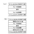
- FIG. 1 shows a schematic configuration of a steel plate provided with a layer containing Zn, Co, and Mo thus formed.
- FIG. 1 (a) shows a case where layers containing Zn, Co, and Mo are formed on both surfaces of a steel plate to be a substrate
- FIG. 1 (b) shows that Ni plating is first applied to both surfaces of a steel plate to be a substrate.
- FIG. 2 (a) shows a structure in which a layer containing Zn, Co, and Mo is formed on both surfaces of a steel plate to be a substrate and an Fe—Ni diffusion layer is formed thereunder, and FIG. 2 (b) is a substrate.
- a layer containing Zn, Co, and Mo, a Fe—Ni diffusion layer, and a softened Ni layer are formed between both surfaces of the steel plate.
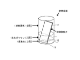
- An evaluation test piece was produced from a steel sheet provided with a layer containing Zn, Co, and Mo of each plating thickness, and the corrosion resistance was investigated by immersing the specimen in bioethanol mixed gasoline. Corrosion resistance was confirmed by the presence or absence of rusting.
- a corrosive solution simulating bioethanol-mixed gasoline was used as a test. As the corrosive liquid, 100 ppm formic acid and 200 ppm acetic acid were added to regular gasoline specified in JIS K2202, and 10% bioethanol specified in JASO M361 was added to purify a simulated deteriorated gasoline.
- corrosive water was prepared by adding 1000 ppm formic acid, 2000 ppm acetic acid, and 1000 ppm chlorine to pure water, and 10 wt% was added to the above deteriorated gasoline to obtain a corrosive liquid.
- the corrosive liquid is in a state where the upper layer is divided into degraded gasoline and the lower layer is divided into two layers of corrosive water. It arrange
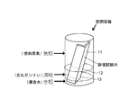
- the evaluation test piece is a gas phase part 11 in contact with fuel vapor (gas phase) of deteriorated gasoline, a liquid phase part 12 in contact with deteriorated gasoline (liquid phase), and an aqueous phase in contact with corrosive water (water phase). It will be separated into part 13.
- steam of an evaluation test piece was evaluated by investigating the corrosion of the gaseous-phase part 11 of an evaluation test piece.
- the evaluation method shown in FIG. 4 used what bent 90 degree
- rusting in the gas phase portion is suppressed by setting the plating thickness of the layer containing Zn, Co, and Mo to be in the range of 1.0 to 8.0 ⁇ m. Further, by forming a Ni layer, a Fe—Ni diffusion layer, or a softened Ni layer under the layer containing Zn, Co, and Mo, rusting in the gas phase portion may be further suppressed. I understood. That is, from the experimental results, when the plating thickness of the layer containing Zn, Co, and Mo was less than 1.0 ⁇ m, sufficient corrosion resistance in the gas phase portion could not be obtained.
- the plating thickness of the layer containing Zn, Co, and Mo exceeds 8.0 ⁇ m
- the surface may be scraped during processing of a pipe tube or the like and wear powder may be generated, which is not preferable.
- the thickness of the layer or the softened Ni layer exceeds 3.0 ⁇ m
- the total thickness of the layer containing Zn, Co and Mo and the Ni layer or the softened Ni layer increases, The surface may be scraped during processing, and wear powder may be generated, which is not preferable.
- ⁇ Pipe processing> Using a steel plate provided with a layer containing Zn, Co, and Mo (and Ni layer, Fe-Ni diffusion layer or softened Ni layer), the shape is corrected by a leveler, and a slitter is used to obtain a predetermined outer diameter. After slitting, the pipe is manufactured into a pipe shape by a molding machine, and pipes are manufactured by seam welding the end faces in the longitudinal direction by high frequency induction welding. As the pipe, there are an oil supply pipe for introducing fuel into the tank, a pipe for introducing fuel from the tank to the engine, and a pipe for venting. As shown in FIG.
- the fuel supply pipe 20 is attached to the fuel tank 23 so as to extend obliquely upward from the upper part of the fuel tank 23. Further, a small-diameter pipe portion 22 that branches from the middle of the large-diameter pipe portion 21 through which the fuel passes and is connected to the upper and lower portions of the large-diameter pipe portion 21 is connected to the fuel supply pipe 20.
- the large diameter pipe part 21 is manufactured using the steel plate of the present invention. In addition, you may manufacture a thin diameter pipe part using the steel plate of this invention.
- regulated by this invention is not restricted to a shape as shown to Fig.5 (a),
- Fig.5 (b) For example, as shown in FIG.5 (b), with the large diameter pipe part 21 which a fuel passes, Even if the small-diameter pipe portion 22 is attached to the fuel tank 23 in an independent shape, the corrosion resistance against the fuel vapor is still particularly required, and thus those of these forms are also included.
- Example 1 A cold-rolled and annealed low carbon aluminum killed steel plate having a thickness of 0.70 mm was used as a plating base plate.
- the components of the steel plate that is the plating original plate are as follows. C: 0.045%, Mn: 0.23%, Si: 0.02%, P: 0.012%, S: 0.009%, Al: 0.063%, N: 0.0036%, balance : Fe and inevitable impurities.
- the steel sheet was subjected to alkaline electrolytic degreasing and pickling with sulfuric acid soaking, to obtain a surface-treated steel sheet provided with a layer containing Zn, Co, and Mo having a thickness of 1 ⁇ m.
- composition ratio of the formed layer containing Zn, Co, and Mo was Co: 0.3%, Mo: 0.01%, and the balance: Zn (% is mass).
- the thickness and composition ratio of the layer containing Zn, Co, and Mo were measured by fluorescent X-ray analysis (ZSX 100e, manufactured by Rigaku).
- Example 2 to 18 After the steel plate of Example 1 was subjected to alkaline electrolytic degreasing and sulfuric acid immersion pickling, The surface-treated steel sheets of Examples 2 to 18 in Table 1 were obtained by changing the thicknesses of the layers containing Zn, Co, and Mo. In Examples 2 to 18, the values of the thickness of the steel plates plated with Ni were listed. Those not plated with Ni were described as having a thickness of zero. For Ni plating, the plating thickness was changed under the conditions of Watt bath matte plating. Other conditions were the same as in Example 1. The Ni plating thickness was measured by fluorescent X-ray analysis (ZSX 100e, manufactured by Rigaku).
- Example 19 After the steel plate of Example 1 was subjected to alkaline electrolytic degreasing and pickling with sulfuric acid immersion, nickel plating with a plating thickness of 2 ⁇ m was obtained under the condition of Watt bath matte plating, to obtain a nickel plated steel plate, Thermal diffusion treatment was performed under conditions of 1 min to form a 1.23 ⁇ m thick Fe—Ni diffusion layer on the surface of the steel plate. Thereafter, a layer containing Zn, Co, and Mo having a thickness of 1 ⁇ m was provided thereon by plating to obtain a surface-treated steel sheet of Example 19 in Table 2. The composition ratio of the formed plating layer containing Zn, Co, and Mo was the same as that in Example 1.
- Example 20 to 32 Steel sheets of Examples 20 to 32 in Table 2 were obtained by changing the thickness of the layer containing Zn, Co, and Mo.
- the value of the thickness of a softened Ni layer formed between the layer containing Zn, Co, and Mo and the Fe—Ni diffusion layer is described. Those that did not form the softened Ni layer were described as having a thickness of zero.
- the plating thickness was changed under the conditions of Watt bath matte plating. The Ni plating thickness was measured by fluorescent X-ray analysis (ZSX 100e, manufactured by Rigaku). Conditions other than the thickness of the layer containing Zn, Co, and Mo, the Ni plating thickness, and the thermal diffusion treatment described in Table 2 were the same as in Example 19.
- the surface-treated steel sheets of Examples 1 to 32 of the present invention were excellent as a pipe material having no rust and corrosion resistance against fuel vapor. Since the above corrosive liquid generates steam that is more corrosive than gasoline, light oil, bioethanol, or biodiesel fuel, if there is no rust in this corrosive liquid test, gasoline, light oil, bioethanol, or biodiesel It is considered that there is no rust on the fuel. On the other hand, the surface-treated steel sheets of Comparative Examples 1 to 11 have red rust and are not practical as a material for producing pipes having corrosion resistance against fuel vapor.
- the surface-treated steel sheet for pipe production according to the present invention can suppress rusting upon exposure to fuel vapor such as gasoline, light oil, bioethanol, or biodiesel fuel. Moreover, the pipe and the oil supply pipe using the surface-treated steel sheet for manufacturing the oil supply pipe of the present invention are excellent in corrosion resistance against fuel vapor, and are highly industrially applicable.
Landscapes
- Chemical & Material Sciences (AREA)
- Engineering & Computer Science (AREA)
- Organic Chemistry (AREA)
- Electrochemistry (AREA)
- Materials Engineering (AREA)
- Metallurgy (AREA)
- Chemical Kinetics & Catalysis (AREA)
- General Engineering & Computer Science (AREA)
- Crystallography & Structural Chemistry (AREA)
- Mechanical Engineering (AREA)
- Other Surface Treatments For Metallic Materials (AREA)
- Physical Vapour Deposition (AREA)
- Electroplating Methods And Accessories (AREA)
Priority Applications (2)
| Application Number | Priority Date | Filing Date | Title |
|---|---|---|---|
| BR112012005991-2A BR112012005991B1 (pt) | 2009-09-18 | 2010-09-16 | TUBULAqAO DE FORNECIMENTO DE COMBUSTIVEL |
| IN2851DEN2012 IN2012DN02851A (ru) | 2009-09-18 | 2010-09-16 |
Applications Claiming Priority (4)
| Application Number | Priority Date | Filing Date | Title |
|---|---|---|---|
| JP2009216693A JP5392718B2 (ja) | 2009-09-18 | 2009-09-18 | 給油パイプ |
| JP2009216714A JP5408777B2 (ja) | 2009-09-18 | 2009-09-18 | 給油パイプ |
| JP2009-216714 | 2009-09-18 | ||
| JP2009-216693 | 2009-09-18 |
Publications (1)
| Publication Number | Publication Date |
|---|---|
| WO2011033775A1 true WO2011033775A1 (ja) | 2011-03-24 |
Family
ID=43758389
Family Applications (1)
| Application Number | Title | Priority Date | Filing Date |
|---|---|---|---|
| PCT/JP2010/005647 WO2011033775A1 (ja) | 2009-09-18 | 2010-09-16 | 燃料蒸気に対する耐食性を有するパイプ製造用表面処理鋼板、その鋼板を用いたパイプおよび給油パイプ |
Country Status (3)
| Country | Link |
|---|---|
| BR (1) | BR112012005991B1 (ru) |
| IN (1) | IN2012DN02851A (ru) |
| WO (1) | WO2011033775A1 (ru) |
Cited By (16)
| Publication number | Priority date | Publication date | Assignee | Title |
|---|---|---|---|---|
| JPWO2013002356A1 (ja) * | 2011-06-30 | 2015-02-23 | 東洋鋼鈑株式会社 | 表面処理鋼板、燃料パイプおよび電池缶 |
| EP2971264A4 (en) * | 2013-03-15 | 2017-05-31 | Modumetal, Inc. | Nanolaminate coatings |
| RU2629347C1 (ru) * | 2013-09-10 | 2017-08-28 | Усуй Ко., Лтд. | Стальной трубопровод для транспортировки топлива |
| CN107130271A (zh) * | 2017-05-25 | 2017-09-05 | 珠海市玛斯特五金塑胶制品有限公司 | 一种供油轨电镀工艺及其专用治具 |
| CN109414738A (zh) * | 2017-01-31 | 2019-03-01 | 亚伯株式会社 | 着色不锈钢板、着色不锈钢卷以及它们的制造方法 |
| US10253419B2 (en) | 2009-06-08 | 2019-04-09 | Modumetal, Inc. | Electrodeposited, nanolaminate coatings and claddings for corrosion protection |
| US10781524B2 (en) | 2014-09-18 | 2020-09-22 | Modumetal, Inc. | Methods of preparing articles by electrodeposition and additive manufacturing processes |
| US10808322B2 (en) | 2013-03-15 | 2020-10-20 | Modumetal, Inc. | Electrodeposited compositions and nanolaminated alloys for articles prepared by additive manufacturing processes |
| US10844504B2 (en) | 2013-03-15 | 2020-11-24 | Modumetal, Inc. | Nickel-chromium nanolaminate coating having high hardness |
| US10961635B2 (en) | 2005-08-12 | 2021-03-30 | Modumetal, Inc. | Compositionally modulated composite materials and methods for making the same |
| US11180864B2 (en) | 2013-03-15 | 2021-11-23 | Modumetal, Inc. | Method and apparatus for continuously applying nanolaminate metal coatings |
| US11286575B2 (en) | 2017-04-21 | 2022-03-29 | Modumetal, Inc. | Tubular articles with electrodeposited coatings, and systems and methods for producing the same |
| US11293272B2 (en) | 2017-03-24 | 2022-04-05 | Modumetal, Inc. | Lift plungers with electrodeposited coatings, and systems and methods for producing the same |
| US11365488B2 (en) | 2016-09-08 | 2022-06-21 | Modumetal, Inc. | Processes for providing laminated coatings on workpieces, and articles made therefrom |
| US11519093B2 (en) | 2018-04-27 | 2022-12-06 | Modumetal, Inc. | Apparatuses, systems, and methods for producing a plurality of articles with nanolaminated coatings using rotation |
| US11692281B2 (en) | 2014-09-18 | 2023-07-04 | Modumetal, Inc. | Method and apparatus for continuously applying nanolaminate metal coatings |
Citations (3)
| Publication number | Priority date | Publication date | Assignee | Title |
|---|---|---|---|---|
| JP2002371933A (ja) * | 2001-06-14 | 2002-12-26 | Honda Motor Co Ltd | 自動車の燃料タンク |
| JP2004346364A (ja) * | 2003-05-21 | 2004-12-09 | Nippon Steel Corp | ゴールドメタリック調意匠性めっき鋼板及びその製造方法 |
| JP2006291281A (ja) * | 2005-04-11 | 2006-10-26 | Toyo Kohan Co Ltd | 黒色めっき鋼板 |
-
2010
- 2010-09-16 WO PCT/JP2010/005647 patent/WO2011033775A1/ja active Application Filing
- 2010-09-16 IN IN2851DEN2012 patent/IN2012DN02851A/en unknown
- 2010-09-16 BR BR112012005991-2A patent/BR112012005991B1/pt not_active IP Right Cessation
Patent Citations (3)
| Publication number | Priority date | Publication date | Assignee | Title |
|---|---|---|---|---|
| JP2002371933A (ja) * | 2001-06-14 | 2002-12-26 | Honda Motor Co Ltd | 自動車の燃料タンク |
| JP2004346364A (ja) * | 2003-05-21 | 2004-12-09 | Nippon Steel Corp | ゴールドメタリック調意匠性めっき鋼板及びその製造方法 |
| JP2006291281A (ja) * | 2005-04-11 | 2006-10-26 | Toyo Kohan Co Ltd | 黒色めっき鋼板 |
Cited By (23)
| Publication number | Priority date | Publication date | Assignee | Title |
|---|---|---|---|---|
| US10961635B2 (en) | 2005-08-12 | 2021-03-30 | Modumetal, Inc. | Compositionally modulated composite materials and methods for making the same |
| US11242613B2 (en) | 2009-06-08 | 2022-02-08 | Modumetal, Inc. | Electrodeposited, nanolaminate coatings and claddings for corrosion protection |
| US10253419B2 (en) | 2009-06-08 | 2019-04-09 | Modumetal, Inc. | Electrodeposited, nanolaminate coatings and claddings for corrosion protection |
| US10544510B2 (en) | 2009-06-08 | 2020-01-28 | Modumetal, Inc. | Electrodeposited, nanolaminate coatings and claddings for corrosion protection |
| JPWO2013002356A1 (ja) * | 2011-06-30 | 2015-02-23 | 東洋鋼鈑株式会社 | 表面処理鋼板、燃料パイプおよび電池缶 |
| US10844504B2 (en) | 2013-03-15 | 2020-11-24 | Modumetal, Inc. | Nickel-chromium nanolaminate coating having high hardness |
| EP2971264A4 (en) * | 2013-03-15 | 2017-05-31 | Modumetal, Inc. | Nanolaminate coatings |
| US11118280B2 (en) | 2013-03-15 | 2021-09-14 | Modumetal, Inc. | Nanolaminate coatings |
| US11180864B2 (en) | 2013-03-15 | 2021-11-23 | Modumetal, Inc. | Method and apparatus for continuously applying nanolaminate metal coatings |
| US11168408B2 (en) | 2013-03-15 | 2021-11-09 | Modumetal, Inc. | Nickel-chromium nanolaminate coating having high hardness |
| US10808322B2 (en) | 2013-03-15 | 2020-10-20 | Modumetal, Inc. | Electrodeposited compositions and nanolaminated alloys for articles prepared by additive manufacturing processes |
| US11851781B2 (en) | 2013-03-15 | 2023-12-26 | Modumetal, Inc. | Method and apparatus for continuously applying nanolaminate metal coatings |
| US10513791B2 (en) | 2013-03-15 | 2019-12-24 | Modumental, Inc. | Nanolaminate coatings |
| RU2629347C1 (ru) * | 2013-09-10 | 2017-08-28 | Усуй Ко., Лтд. | Стальной трубопровод для транспортировки топлива |
| US11560629B2 (en) | 2014-09-18 | 2023-01-24 | Modumetal, Inc. | Methods of preparing articles by electrodeposition and additive manufacturing processes |
| US10781524B2 (en) | 2014-09-18 | 2020-09-22 | Modumetal, Inc. | Methods of preparing articles by electrodeposition and additive manufacturing processes |
| US11692281B2 (en) | 2014-09-18 | 2023-07-04 | Modumetal, Inc. | Method and apparatus for continuously applying nanolaminate metal coatings |
| US11365488B2 (en) | 2016-09-08 | 2022-06-21 | Modumetal, Inc. | Processes for providing laminated coatings on workpieces, and articles made therefrom |
| CN109414738A (zh) * | 2017-01-31 | 2019-03-01 | 亚伯株式会社 | 着色不锈钢板、着色不锈钢卷以及它们的制造方法 |
| US11293272B2 (en) | 2017-03-24 | 2022-04-05 | Modumetal, Inc. | Lift plungers with electrodeposited coatings, and systems and methods for producing the same |
| US11286575B2 (en) | 2017-04-21 | 2022-03-29 | Modumetal, Inc. | Tubular articles with electrodeposited coatings, and systems and methods for producing the same |
| CN107130271A (zh) * | 2017-05-25 | 2017-09-05 | 珠海市玛斯特五金塑胶制品有限公司 | 一种供油轨电镀工艺及其专用治具 |
| US11519093B2 (en) | 2018-04-27 | 2022-12-06 | Modumetal, Inc. | Apparatuses, systems, and methods for producing a plurality of articles with nanolaminated coatings using rotation |
Also Published As
| Publication number | Publication date |
|---|---|
| IN2012DN02851A (ru) | 2015-07-24 |
| BR112012005991B1 (pt) | 2020-11-24 |
| BR112012005991A2 (pt) | 2016-11-22 |
Similar Documents
| Publication | Publication Date | Title |
|---|---|---|
| WO2011033775A1 (ja) | 燃料蒸気に対する耐食性を有するパイプ製造用表面処理鋼板、その鋼板を用いたパイプおよび給油パイプ | |
| JP5649076B2 (ja) | 燃料蒸気に対する耐食性を有する給油パイプ | |
| JP3045612B2 (ja) | 高耐食性ニッケルめっき鋼帯およびその製造法 | |
| RU2520847C1 (ru) | Листовая сталь для горячего штампования и способ изготовления горячештампованной детали с использованием листовой стали для горячего штампования | |
| JP5861249B2 (ja) | 容器用鋼板の製造方法 | |
| JP6400140B2 (ja) | 表面処理鋼板の製造方法、および電池缶の製造方法 | |
| JP5392717B2 (ja) | 給油パイプ | |
| JP5392718B2 (ja) | 給油パイプ | |
| WO2015125465A1 (ja) | 高強度鋼板およびその製造方法 | |
| JP5867927B2 (ja) | 燃料蒸気への耐食性に優れたパイプ製造用鋼板、それを用いたパイプ及びパイプの製造方法 | |
| WO2011135787A1 (ja) | 燃料蒸気に対する耐食性を有するパイプ製造用めっき鋼板、そのめっき鋼板を用いたパイプ及び給油パイプ | |
| JP5309862B2 (ja) | 部材加工後の化成処理性に優れた鋼材およびその製造方法 | |
| JP5408777B2 (ja) | 給油パイプ | |
| WO2015087529A1 (ja) | 耐アルコール孔食性および耐アルコールscc性に優れた鋼材 | |
| WO2014087628A1 (ja) | 耐アルコール孔食性および耐アルコールscc性に優れた鋼材 | |
| JP2006037220A (ja) | 塗膜密着性と耐塗装下腐食性に優れた高クロム鋼 | |
| JP6354915B1 (ja) | 自動二輪車燃料タンク用鋼板および燃料タンク部材 | |
| JP2010280981A (ja) | 塩害耐食性に優れた自動車用燃料タンク用表面処理ステンレス鋼板 | |
| WO2015125464A1 (ja) | 高強度鋼板およびその製造方法 |
Legal Events
| Date | Code | Title | Description |
|---|---|---|---|
| 121 | Ep: the epo has been informed by wipo that ep was designated in this application |
Ref document number: 10816889 Country of ref document: EP Kind code of ref document: A1 |
|
| NENP | Non-entry into the national phase |
Ref country code: DE |
|
| WWE | Wipo information: entry into national phase |
Ref document number: 2851/DELNP/2012 Country of ref document: IN |
|
| 122 | Ep: pct application non-entry in european phase |
Ref document number: 10816889 Country of ref document: EP Kind code of ref document: A1 |
|
| REG | Reference to national code |
Ref country code: BR Ref legal event code: B01A Ref document number: 112012005991 Country of ref document: BR |
|
| ENP | Entry into the national phase |
Ref document number: 112012005991 Country of ref document: BR Kind code of ref document: A2 Effective date: 20120316 |