WO2011033714A1 - 空気調和機 - Google Patents
空気調和機 Download PDFInfo
- Publication number
- WO2011033714A1 WO2011033714A1 PCT/JP2010/004828 JP2010004828W WO2011033714A1 WO 2011033714 A1 WO2011033714 A1 WO 2011033714A1 JP 2010004828 W JP2010004828 W JP 2010004828W WO 2011033714 A1 WO2011033714 A1 WO 2011033714A1
- Authority
- WO
- WIPO (PCT)
- Prior art keywords
- obstacle
- area
- determined
- person
- position determination
- Prior art date
Links
Images


Classifications
-
- F—MECHANICAL ENGINEERING; LIGHTING; HEATING; WEAPONS; BLASTING
- F24—HEATING; RANGES; VENTILATING
- F24F—AIR-CONDITIONING; AIR-HUMIDIFICATION; VENTILATION; USE OF AIR CURRENTS FOR SCREENING
- F24F11/00—Control or safety arrangements
- F24F11/70—Control systems characterised by their outputs; Constructional details thereof
- F24F11/72—Control systems characterised by their outputs; Constructional details thereof for controlling the supply of treated air, e.g. its pressure
- F24F11/79—Control systems characterised by their outputs; Constructional details thereof for controlling the supply of treated air, e.g. its pressure for controlling the direction of the supplied air
-
- F—MECHANICAL ENGINEERING; LIGHTING; HEATING; WEAPONS; BLASTING
- F24—HEATING; RANGES; VENTILATING
- F24F—AIR-CONDITIONING; AIR-HUMIDIFICATION; VENTILATION; USE OF AIR CURRENTS FOR SCREENING
- F24F1/00—Room units for air-conditioning, e.g. separate or self-contained units or units receiving primary air from a central station
- F24F1/0007—Indoor units, e.g. fan coil units
- F24F1/0011—Indoor units, e.g. fan coil units characterised by air outlets
-
- F—MECHANICAL ENGINEERING; LIGHTING; HEATING; WEAPONS; BLASTING
- F24—HEATING; RANGES; VENTILATING
- F24F—AIR-CONDITIONING; AIR-HUMIDIFICATION; VENTILATION; USE OF AIR CURRENTS FOR SCREENING
- F24F1/00—Room units for air-conditioning, e.g. separate or self-contained units or units receiving primary air from a central station
- F24F1/0007—Indoor units, e.g. fan coil units
- F24F1/0041—Indoor units, e.g. fan coil units characterised by exhaustion of inside air from the room
-
- F—MECHANICAL ENGINEERING; LIGHTING; HEATING; WEAPONS; BLASTING
- F24—HEATING; RANGES; VENTILATING
- F24F—AIR-CONDITIONING; AIR-HUMIDIFICATION; VENTILATION; USE OF AIR CURRENTS FOR SCREENING
- F24F11/00—Control or safety arrangements
- F24F11/62—Control or safety arrangements characterised by the type of control or by internal processing, e.g. using fuzzy logic, adaptive control or estimation of values
-
- F—MECHANICAL ENGINEERING; LIGHTING; HEATING; WEAPONS; BLASTING
- F24—HEATING; RANGES; VENTILATING
- F24F—AIR-CONDITIONING; AIR-HUMIDIFICATION; VENTILATION; USE OF AIR CURRENTS FOR SCREENING
- F24F2120/00—Control inputs relating to users or occupants
- F24F2120/10—Occupancy
- F24F2120/12—Position of occupants
Definitions
- the present invention relates to an air conditioner in which an indoor unit is provided with an obstacle detection device that detects the presence or absence of an obstacle, and the wind direction is determined based on the detection result of the obstacle detection device.
- a conventional air conditioner includes a human body detection device having a human body detection sensor such as a pyroelectric infrared sensor and an ultrasonic sensor for detecting a distance to an object in an indoor unit.
- a human body detection sensor such as a pyroelectric infrared sensor and an ultrasonic sensor for detecting a distance to an object in an indoor unit.
- the wind direction changing means composed of the upper and lower blades and the left and right blades is controlled to send the conditioned air toward an area where no people are present (for example, see Patent Document 1).
- the wind direction changing means is controlled in a direction in which there is no obstacle.
- air conditioning is performed directly on the obstacle. The wind direction changing means is controlled so that the wind does not hit and the conditioned air spreads throughout the room.
- the wind direction changing means is controlled so that the conditioned air spreads throughout the room. Determine whether there is an obstacle in the absence area, and if there is an obstacle, control the wind direction control means in the direction of the obstacle so that the conditioned air does not hit the obstacle strongly, but there is no obstacle In this case, the wind direction control means is controlled in a direction where there is no obstacle (see, for example, Patent Document 2).
- JP 63-143449 A Japanese Utility Model Publication No. 3-72249
- the air-conditioning efficiency is improved by controlling the wind direction changing means based on the detection signal of the human position detection means and the detection signal of the obstacle position detection means, but a table is provided in the room. Because there are many obstacles of various sizes such as furniture such as sofas, TVs, audios, etc., it cannot be said that practical wind direction control methods for such situations are sufficiently disclosed, and such control There is still room for improvement in terms of optimal air conditioning alone.
- the present invention has been made in view of such problems of the prior art, and performs obstacle size determination with high accuracy and efficiency and finely controls the wind direction based on these determination results. It aims to provide an air conditioner with improved air conditioning efficiency.
- the present invention is an air conditioner including an indoor unit including an obstacle detection device that detects the presence or absence and size of an obstacle, and left and right blades that change the air blowing direction to the left and right. If there are multiple obstacle areas where obstacles exist in the area to be air-conditioned based on the detection results by the obstacle detection device, and it is determined that the size of the obstacles in each obstacle area is different, The airflow is controlled by blowing the air toward the obstacle area where the small obstacle exists by controlling the blade.
- the left and right blades are swung to blow air toward the obstacle area where a small obstacle exists.
- the air conditioner further includes a human body detection device that detects the presence or absence of a person, and based on the detection results of the human body detection device and the obstacle detection device, there is a person in the area to be air-conditioned.
- a human body detection device that detects the presence or absence of a person, and based on the detection results of the human body detection device and the obstacle detection device, there is a person in the area to be air-conditioned.
- the left and right blades are controlled to perform airflow control for blowing air toward the obstacle area where a small obstacle exists.
- the area to be air-conditioned is divided into a plurality of human position determination areas detected by the human body detection device, and is divided into a plurality of obstacle position determination areas detected by the obstacle detection device, At least one obstacle position determination area belongs to each of the plurality of person position determination areas, and the airflow control is performed for the obstacle position determination area belonging to the person position determination area determined by the human body detection device Or it is a case where it is determined by the obstacle detection device that there is an obstacle in the obstacle position determination area located in front of the person position determination area determined to have a person.
- each of the plurality of human position determination areas is divided into either a first area or a second area farther than the first area according to the distance from the indoor unit, and human body detection is performed.
- the person position determination area determined by the apparatus as having a person and the obstacle position determination area determined as having an obstacle by the obstacle detection apparatus both belong to the first area.
- the air conditioner when the air conditioner has one obstacle position determination area that is determined by the obstacle detection device to have no obstacle, the air conditioner is located within that area with the one obstacle position determination area as the center. Perform airflow control.
- the air conditioner when the obstacle detection device determines that there are no obstacles in the two obstacle position determination areas adjacent to each other, the air conditioner has an air flow with the centers of the two obstacle position determination areas as both ends. Take control.
- the air conditioner determines that there are no obstacles in the two obstacle position determination areas that are not adjacent to each other by the obstacle detection device, the air conditioner has airflow with the centers of the two obstacle position determination areas as both ends. Take control.
- the air conditioner has been determined by the obstacle detection device that there are obstacles in all the obstacle position determination regions belonging to the human position determination region determined by the human body detection device.
- airflow control is performed around the obstacle determination area in which it is determined that the obstacle is smaller.
- two obstacle position determination areas belong to the person position determination area determined to have a person by the human body detection device, and the obstacle detection apparatus determines that there is an obstacle in one area.
- the air conditioner performs airflow control in the other area.
- the two obstacle position determination areas belong to the person position determination area determined to have a person by the human body detection device, and both of the two obstacle position determination areas If the obstacle detection device determines that there is an obstacle, the airflow in that area is determined mainly by the obstacle detection area in which the obstacle is determined to be smaller in the person position determination area in which it is determined that there is a person. Take control.
- each of the plurality of human position determination areas is either a first area or a second area farther than the first area according to the distance from the indoor unit.
- the person position determination area that is divided and determined to have a person by the human body detection device belongs to the second area, and is one of the two obstacle determination areas that belong to the person position determination area that has been determined to have a person. It is determined by the obstacle detection device that there is no obstacle, it is determined that there is an obstacle in the obstacle determination area located in front of one obstacle determination area determined that there is no obstacle, and the obstacle is When it is determined that there is no obstacle in any of the obstacle determination areas on both sides of the obstacle determination area determined to be present, airflow control is performed in one area.
- each of the plurality of human position determination areas is divided into either a first area or a second area farther than the first area according to the distance from the indoor unit, and human body detection is performed.
- the person position determination area determined to have a person by the device belongs to the second area, and it is determined that there are two obstacle determination areas or persons belonging to the person position determination area determined to have a person.
- the air conditioner performs airflow control in the other region.
- each of the plurality of human position determination areas is divided into either a first area or a second area farther than the first area according to the distance from the indoor unit, and human body detection is performed.
- the person position determination area determined to have a person by the device belongs to the second area, and it is determined that there are two obstacle determination areas or persons belonging to the person position determination area determined to have a person. If the obstacle detection device determines that there is an obstacle in both of the two obstacle position determination areas located in front of the person position determination area, the air conditioner The air flow control is performed in the area around the obstacle discrimination area determined to be smaller.
- the air conditioner includes a plurality of left and right blades that can be controlled independently on the left and right blades.
- the conditioned air can be sent toward a region where the obstacles are smaller.
- the air conditioning efficiency is improved even in a difficult state.
- FIG. 1 is a front view of an indoor unit of an air conditioner according to the present invention.
- 2 is a longitudinal sectional view of the indoor unit of FIG. 3 is a longitudinal sectional view of the indoor unit of FIG. 1 with the movable front panel opening the front opening and the upper and lower blades opening the outlet.
- 4 is a longitudinal sectional view of the indoor unit of FIG. 1 in a state where the lower blades constituting the upper and lower blades are set downward.
- FIG. 5 is a schematic view showing a human position determination area detected by a sensor unit constituting the human body detection device provided in the indoor unit of FIG.
- FIG. 6 is a flowchart for setting region characteristics for each region shown in FIG. FIG.
- FIG. 7 is a flowchart for finally determining the presence or absence of a person in each area shown in FIG.
- FIG. 8 is a timing chart showing the presence / absence determination of a person by each sensor unit
- 9 is a schematic plan view of a residence where the indoor unit of FIG. 1 is installed.
- FIG. 10 is a graph showing the long-term cumulative result of each sensor unit in the residence of FIG. 11 is a schematic plan view of another residence in which the indoor unit of FIG. 1 is installed.
- FIG. 12 is a graph showing the long-term cumulative result of each sensor unit in the residence of FIG. 13 is a cross-sectional view of the obstacle detection device provided in the indoor unit of FIG.
- FIG. 14 is a schematic diagram showing an obstacle position determination area detected by the obstacle detection device.
- FIG. 14 is a schematic diagram showing an obstacle position determination area detected by the obstacle detection device.
- FIG. 15 is a block diagram showing a driving circuit of an ultrasonic sensor constituting the obstacle detection device.
- FIG. 16 is a configuration diagram of a latch circuit unit constituting a drive circuit of the ultrasonic sensor.
- FIG. 17 is a timing chart showing the state of each signal in the drive circuit of the ultrasonic sensor of FIG.
- FIG. 18 is a flowchart showing distance measurement to an obstacle at the start of operation of the air conditioner.
- FIG. 19 is a timing chart showing noise detection processing by the drive circuit of the ultrasonic sensor of FIG.
- FIG. 20 is a schematic diagram illustrating the ultrasonic reach distance corresponding to the distance number indicating the distance from the ultrasonic sensor to the position P.
- FIG. 21 is a timing chart showing reception processing by the driving circuit of the ultrasonic sensor of FIG. FIG.
- FIG. 22 is a flowchart showing distance measurement to an obstacle when the air conditioner is stopped.
- FIG. 23 is a schematic elevation view of the indoor unit installation space when the mask time for detecting the presence or absence of an obstacle is set according to the distance from the indoor unit
- FIG. 24 is a flowchart in the case where two threshold values are set as threshold values used for determining the presence or absence of an obstacle.
- FIG. 25 is a flowchart showing learning control for obstacle detection.
- FIG. 26 is a flowchart illustrating a modification of learning control for obstacle detection.
- FIG. 27 is a schematic diagram showing the definition of the wind direction at each position of the left and right blades constituting the left and right blades.
- FIG. 28 is a schematic plan view of a room for explaining a wall detection algorithm for measuring a distance from an indoor unit to a surrounding wall surface to obtain a distance number.
- FIG. 29 is a schematic view showing a state in which a transmission wave from an ultrasonic sensor is reflected at a corner portion.
- FIG. 30 is a flowchart for correcting the distance numbers of the front and left and right wall surfaces.
- FIG. 31 is a flowchart for recognizing the installation position and room shape of an indoor unit.
- FIG. 32A is a schematic diagram showing the swing range of the left and right blades when the indoor unit is centrally installed.
- FIG. 32B is a schematic diagram showing the swing range of the left and right blades when the indoor unit is installed near the right wall.
- FIG. 32C is a schematic diagram showing the swing range of the left and right blades when the indoor unit is installed near the left wall.
- FIGS. 1 to 4 show the indoor unit of the air conditioner according to the present invention. ing.
- the indoor unit has a main body 2 and a movable front panel (hereinafter simply referred to as a front panel) 4 that can freely open and close the front opening 2a of the main body 2, and the front panel 4 is the main body 2 when the air conditioner is stopped. While the front opening 2a is closed in close contact with the front, the front panel 4 moves in a direction away from the main body 2 to open the front opening 2a during operation of the air conditioner.
- 1 and 2 show a state where the front panel 4 closes the front opening 2a
- FIGS. 3 and 4 show a state where the front panel 4 opens the front opening 2a.
- the heat exchanger 6 and the indoor air taken in from the front opening 2 a and the upper opening 2 b are heat-exchanged by the heat exchanger 6 and are indoors.
- a filter 16 is provided between the front opening 2a and the upper surface opening 2b and the heat exchanger 6 for removing dust contained in the indoor air taken in from the front opening 2a and the upper surface opening 2b.
- the upper part of the front panel 4 is connected to the upper part of the main body 2 via two arms 18 and 20 provided at both ends thereof, and a drive motor (not shown) connected to the arm 18 is driven and controlled.
- a drive motor (not shown) connected to the arm 18 is driven and controlled.
- the upper and lower blades 12 are composed of an upper blade 12a and a lower blade 12b, and are respectively swingably attached to the lower portion of the main body 2.
- the upper blade 12a and the lower blade 12b are connected to separate drive sources (for example, stepping motors), and are independently controlled by a control device (first board 48, for example, a microcomputer described later) built in the indoor unit. Angle controlled.
- first board 48 for example, a microcomputer described later
- the upper and lower blades 12 can be composed of three or more upper and lower blades. In this case, at least two (particularly, the uppermost blade and the lowermost blade) can be independently angle-controlled. Is preferred.
- the left and right blades 14 are composed of a total of 10 blades arranged five by left and right from the center of the indoor unit, and are respectively swingably attached to the lower part of the main body 2.
- the left and right five blades are connected to separate drive sources (for example, stepping motors) as a unit, and the left and right five blades are independently angle-controlled by a control device built in the indoor unit. .
- a method for driving the left and right blades 14 will also be described later.
- a plurality of (for example, three) fixed sensor units 24, 26, and 28 are attached to the upper portion of the front panel 4 as a human body detection device. , 28 are held by a sensor holder 36 as shown in FIGS. 3 and 4.
- Each sensor unit 24, 26, 28 is composed of a circuit board, a lens attached to the circuit board, and a human body detection sensor mounted inside the lens.
- the human body detection sensor is composed of a pyroelectric infrared sensor that detects the presence or absence of a person by detecting infrared rays radiated from the human body, for example, and outputs in accordance with a change in the amount of infrared rays detected by the infrared sensor.
- the presence or absence of a person is determined by the circuit board based on the pulse signal. That is, the circuit board acts as presence / absence determination means for determining the presence / absence of a person.
- FIG. 5 shows human position determination areas detected by the sensor units 24, 26, and 28.
- the sensor units 24, 26, and 28 can detect whether or not a person is in the next area.
- Sensor unit 24 area A + B + C + D
- Sensor unit 26 Area B + C + E + F
- Sensor unit 28 area C + D + F + G That is, in the air conditioner indoor unit according to the present invention, the areas that can be detected by the sensor units 24, 26, and 28 are partially overlapped, and a smaller number of sensor units than the number of the areas A to G are used. Thus, the presence or absence of a person in each of the areas A to G is detected.
- Table 1 shows the relationship between the outputs of the sensor units 24, 26, and 28 and the presence determination area (area determined to have a person). In Table 1 and the following description, the sensor units 24, 26, 28 are referred to as a first sensor 24, a second sensor 26, and a third sensor 28.
- FIG. 6 is a flowchart for setting region characteristics to be described later in each of the regions A to G using the first to third sensors 24, 26, and 28.
- FIG. 7 illustrates the first to third sensors.
- FIG. 6 is a flowchart for determining in which of the regions A to G a person is present using the sensors 24, 26, and 28, and a person position determination method will be described below with reference to these flowcharts.
- step S1 the presence / absence of a person in each area is first determined at a predetermined period T1 (for example, 5 seconds).
- a predetermined period T1 for example, 5 seconds.
- each of the areas A to G is divided into a first area where the person is good (a place where the person is good) and a second area where the person is short (the area where the person simply passes, and the stay time is short). And a third area (a non-living area such as a wall or a window where people hardly go).
- the first region, the second region, and the third region are referred to as a life category I, a life category II, and a life category III, respectively, and the life category I, the life category II, and the life category III are respectively a region characteristic I. It can also be said that the region of region characteristic II, region of region characteristic II, region of region characteristic III.
- the life category I (region characteristic I) and the life category II (region characteristic II) are combined into a life region (region where people live), while the life category III (region characteristic III) is changed to a non-life region (
- the area of life may be broadly classified according to the frequency of the presence or absence of a person.
- FIG. 9 shows a case where the indoor unit of the air conditioner according to the present invention is installed in an LD of 1 LDK comprising one Japanese-style room, an LD (living room / dining room) and a kitchen, and is indicated by an ellipse in FIG.
- the area shows the well-placed place where the subject reported.
- the presence / absence of a person in each of the regions A to G is determined every period T1, and 1 (with a reaction) or 0 (without a reaction) is output as a reaction result (determination) in the period T1, Is repeated a plurality of times, and in step S2, all sensor outputs are cleared.
- step S3 it is determined whether or not the cumulative operation time of the predetermined air conditioner has elapsed. If it is determined in step S3 that the predetermined time has not elapsed, the process returns to step S1. On the other hand, if it is determined that the predetermined time has elapsed, the reaction results accumulated in the predetermined time in each of the regions A to G are two. Each region A to G is identified as one of the life categories I to III by comparing with the threshold value.
- a first threshold value and a second threshold value smaller than the first threshold value are set, and in step S4, the long-term accumulation result of each of the regions A to G is obtained. It is determined whether or not it is greater than the first threshold value, and the region determined to be greater is determined to be the life category I in step S5. If it is determined in step S4 that the long-term accumulation result of each region A to G is less than the first threshold value, whether or not the long-term accumulation result of each region A to G is greater than the second threshold value in step S6.
- the region determined to be large is determined to be the life category II in step S7, while the region determined to be small is determined to be the life category III in step S8.
- the regions C, D, and G are determined as the life category I
- the regions B and F are determined as the life category II
- the regions A and E are determined as the life category III.
- FIG. 11 shows a case where the indoor unit of the air conditioner according to the present invention is installed in another LD of 1 LDK, and FIG. 12 discriminates each region A to G based on the long-term accumulation result in this case. Results are shown.
- the areas B, C, and E are determined as the life category I
- the areas A and F are determined as the life category II
- the areas D and G are determined as the life category III.
- step S23 it is determined whether or not a predetermined number M (for example, 15 times) of reaction results in the period T1 has been obtained. If it is determined that the period T1 has not reached the predetermined number M, the process returns to step S21. If it is determined that the period T1 has reached the predetermined number M, in step S24, the total number of reaction results in the period T1 ⁇ M is used as the cumulative reaction period number, and the cumulative reaction period number for one time is calculated.
- a predetermined number M for example, 15 times
- step S27 by subtracting 1 from the number of times (N) of cumulative reaction period calculations and returning to step S21, the calculation of the cumulative reaction period number for a predetermined number of times is repeatedly performed.
- Table 2 shows a history of reaction results for the latest one time (time T1 ⁇ M).
- ⁇ A0 means the number of cumulative reaction periods for one time in the region A.
- the cumulative reaction period number of one time immediately before ⁇ A0 is ⁇ A1
- the previous cumulative reaction period number of ⁇ A0 is ⁇ A2,...
- N 4
- the past four history ( ⁇ A4, ⁇ A3 , .SIGMA.A2, .SIGMA.A1), for life category I it is determined that there is a person if the cumulative reaction period is one or more.
- life category II it is determined that there is a person if the cumulative reaction period of one or more times is two or more in the past four history
- life category III the past four history Among them, if the cumulative reaction period number of 2 times or more is 3 times or more, it is determined that there is a person.
- the presence / absence of the person is similarly estimated from the past four histories, life categories, and cumulative reaction period times.
- the presence / absence of a person is estimated using a smaller number of sensors than the number of discrimination areas A to G. Since there is a possibility that the position is incorrect, avoiding human position estimation in a single predetermined period regardless of whether it is an overlapping area, the region characteristics obtained by accumulating the region determination results for each predetermined period over a long period, and for each predetermined period The region determination results are accumulated N times, and the location of the person is estimated from the past history of the accumulated reaction period times of each region obtained, thereby obtaining the position estimation result of the person with high probability.
- each area to G Region characteristics (life categories I to III) are determined, and the time required for presence estimation and the time required for absence estimation are changed according to the region characteristics of the regions A to G.
- the time required for estimating the presence / absence of the area determined as the life category II as a standard in the area determined as the life category I, there is a person at a shorter time interval than the area determined as the life category II. In contrast, when there are no people in the area, the absence of the person is estimated at a longer time interval than the area determined as the life category II.
- the time required for estimation is set to be long.
- the presence of a person is estimated at a longer time interval than the area determined to be life category II.
- an obstacle detection device 30 is provided at the lower part of one side (left side when viewed from the front) of the main body 2, and the obstacle detection device 30 will be described with reference to FIG. .
- the term “obstacle” refers to all objects that are blown out from the air outlet 10 of the indoor unit and impede the flow of air to provide a comfortable space for residents. It is a collective term for non-residents such as furniture such as sofas, televisions, and audio.
- the obstacle detection device 30 includes an ultrasonic distance sensor (hereinafter simply referred to as “ultrasonic sensor”) 32 as a distance detection means, a spherical support 34 that rotatably supports the ultrasonic sensor 32, and an ultrasonic wave.
- a horn 36 formed on the support 34 positioned in the sound wave exit direction of the sensor 32, and a distance detection direction changing means (driving means) for changing the distance detection direction by changing the direction of the ultrasonic sensor 32 are provided. Yes.
- the horn 36 is for improving the sensitivity of the ultrasonic wave transmitted by the ultrasonic sensor 32 and enhancing the directivity to improve the obstacle detection accuracy.
- the support 34 has a horizontal (horizontal) rotating shaft 40 and a vertical (vertical) rotating shaft 42 extending in a direction orthogonal to the horizontal rotating shaft 40, and the horizontal rotating shaft 40 is
- the horizontal rotation motor 44 is connected to and driven
- the vertical rotation shaft 42 is connected to and driven by the vertical rotation motor 46.
- the distance detection direction changing means includes a horizontal rotation motor 44, a vertical rotation motor 46, and the like, and can change the direction angle of the ultrasonic sensor 32 two-dimensionally and be directed to the ultrasonic sensor 32. The direction angle can be recognized.
- the ultrasonic sensor 32 serves as both an ultrasonic transmitter and a receiver.
- the ultrasonic sensor 32 transmits an ultrasonic pulse.
- the ultrasonic sensor 32 reflects the reflected wave.
- the ultrasonic transmission unit and the reception unit of the ultrasonic sensor 32 are separate, there is no change in principle or function, and the ultrasonic sensor 32 can be adopted in the present embodiment.
- the direction in which the ultrasonic sensor 32 is directed by the distance detection direction changing means is changed to a vertical angle (a depression angle, an angle measured downward from the horizontal line) ⁇ , a horizontal angle (a reference on the left side when viewed from the indoor unit).
- the angle measured to the right from the line) ⁇ ⁇ .
- the position of the person or the object in the living space is recognized by changing the vertical angle ⁇ and the horizontal angle ⁇ at predetermined angular intervals and causing the ultrasonic sensor 32 to perform a detection operation (scanning). Can do.
- the floor surface of the living space is subdivided as shown in FIG. 14 by the ultrasonic sensor 32 based on the vertical angle ⁇ and the horizontal angle ⁇ , and each of these areas is obstructed. It is defined as a position determination area or “position”, and it is determined which position an obstacle is present. Note that all the positions shown in FIG. 14 substantially coincide with all the areas of the human position determination area shown in FIG. 5, and the area boundary in FIG. 5 is substantially coincident with the position boundary in FIG. By making it correspond as follows, the air conditioning control described later can be easily performed, and the memory to be stored is reduced as much as possible.
- the number of position areas is set to be larger than the number of areas of the human position determination area, and at least two positions belong to each of the human position determination areas.
- the air conditioning control can be performed by dividing the area so that at least one position belongs to each person position determination area.
- each of the plurality of person position determination areas is divided according to the distance to the indoor unit, and the number of positions belonging to the person position determination area in the near area is determined as the person position determination in the far area.
- the number of positions belonging to the area is set to be larger than the number of areas belonging to the area, but the number of positions belonging to each person position determination area may be the same regardless of the distance from the indoor unit.
- the air conditioner according to the present invention detects the presence or absence of a person in the regions A to G by the human body detection device, and detects the presence or absence of an obstacle in the positions A1 to G2 by the obstacle detection device. Based on the detection signal (detection result) of the human body detection device and the detection signal (detection result) of the obstacle detection device, driving and controlling the upper and lower blades 12 and the left and right blades 14 which are wind direction changing means provides a comfortable space. I am doing so.
- the human body detection sensor can detect the presence or absence of a person by detecting infrared rays emitted from the human body, for example, the obstacle detection device receives a reflected wave of the transmitted ultrasonic wave to Since the distance of an object is detected, it is impossible to distinguish between a person and an obstacle.
- the area where the person is located may not be air-conditioned, or the person may be directly conditioned by air-conditioning airflow (airflow), resulting in inefficient air conditioning control or discomfort to the person. There is a risk of air conditioning control.
- the obstacle detection apparatus detects only the obstacle by performing the data processing described below.
- the main body 2 includes three boards 48, 50, and 52 that are electrically connected to each other, and includes a front panel 4, upper and lower blades 12, and left and right blades attached to the main body 2.
- the movable parts such as 14 are controlled by the first substrate 48, and the third substrate 52 is mounted integrally with the ultrasonic sensor 32.
- the second substrate 50 is provided with a sensor input amplification unit 54, a band amplification unit 56, a comparison unit 58, and a latch circuit unit 60, and an ultrasonic transmission signal output from the first substrate 48.
- the ultrasonic sensor 32 transmits an ultrasonic wave toward each address to be described later based on the input signal, receives the reflected wave, and outputs it to the band amplifying unit 56.
- As the ultrasonic transmission signal for example, a 50 kHz signal with 50% duty that repeats ON / OFF at 10 ⁇ s is used, and the band amplification unit 56 amplifies a signal in the vicinity of 50 kHz.
- the output signal of the band amplifier 56 is input to the comparator 58 and compared with a predetermined threshold set in the comparator 58.
- the comparison unit 58 outputs an L level (low level) signal to the latch circuit unit 60 when the output signal of the band amplifying unit 56 is larger than the threshold value, whereas the comparison unit 58 outputs H when the output signal of the band amplifying unit 56 is smaller than the threshold value.
- a level (high level) signal is output to the latch circuit unit 60.
- the first substrate 48 outputs a reception mask signal for separating noise to the latch circuit unit 60.
- FIG. 15 shows the ultrasonic sensor 32 having a transmission / reception integrated type, but it is of course possible to use a transmitter and a receiver separately.
- FIG. 16 shows a latch circuit unit 60 configured by RS (reset set) flip-flops.
- Table 4 shows two inputs (input from the comparison unit 58 (RESET input) and from the first substrate 48. The output (Q) from the latch circuit unit 60 determined based on the input (SET input) is shown.
- H * indicates whether the output is H level when both the RESET input and the SET input are at the L level, and which is the H level first when both the RESET input and the SET input are at the H level. The output level is different.
- FIG. 17 is a schematic timing chart showing the state of each signal.
- the comparison circuit 58 sends an H level signal to the latch circuit 60. A signal is input.
- the ultrasonic wave is output.
- the sensor 32 transmits an ultrasonic wave toward the set address.
- the comparison unit 58 compares the input signal with a preset threshold value, and outputs an L level signal to the latch circuit unit 60 if it is greater than the threshold value.
- the signal input to the comparison unit 58 at this time is not a signal generated by the ultrasonic sensor 32 receiving the reflected wave from the living space, a predetermined sensor output mask time from the transmission of the ultrasonic transmission signal is obtained. And the L level reception mask signal is output from the first substrate 48 to the latch circuit portion 60 of the second substrate 50 during the sensor output mask time.
- the ultrasonic reception signal output from the latch circuit 60 to the first substrate 48 is maintained at the H level.
- the ultrasonic wave transmitted from the ultrasonic sensor 32 is reflected in the living space, and this reflected wave (first wave) is received by the ultrasonic sensor 32 and input to the comparison unit 58 via the band amplification unit 56.
- this reflected wave first wave
- an L level signal is output to the latch circuit unit 60.
- the sensor output mask time is set to be shorter than the time interval from ultrasonic transmission to reception of the reflected wave
- the reception mask signal at this time is at the H level.
- the ultrasonic reception signal output to one substrate 48 is at the L level.
- the time during which the ultrasonic reception signal is maintained at the H level means the time t until the ultrasonic sensor 32 transmits the ultrasonic wave and receives the reflected wave (first wave).
- the first substrate 48 transmits an ultrasonic sensor horizontal drive signal to the horizontal rotation motor driver 62 to drive the horizontal rotation motor 44 and
- the address to be measured is changed by transmitting the sound wave sensor vertical drive signal to the vertical rotation motor driver 64 and driving the vertical rotation motor 46.
- I and j in Table 5 indicate addresses to be measured, and the vertical angle and the horizontal angle are the above-described depression angle ⁇ and the angle ⁇ measured rightward from the left reference line when viewed from the indoor unit. Each is shown. That is, when viewed from the indoor unit, each address is set in the range of 5 to 80 degrees in the vertical direction and 10 to 170 degrees in the horizontal direction, and the ultrasonic sensor 32 measures each address and scans the living space. .
- distance measurement (obstacle position detection) is performed in this order at each address from address [0, 0] to address [32, 0], and then the address [32, 1 ] To the address [0, 1], the distance is measured in this order, and the scanning at the start of the operation of the air conditioner is completed.
- the reason why the entire scanning of the living space by the ultrasonic sensor 32 is performed separately when the operation of the air conditioner is started and when the operation is stopped is to efficiently determine whether there is an obstacle. That is, when the operation is stopped, all the movable elements such as the compressor are stopped, and it is less susceptible to noise than when the air conditioner is started. If the entire scanning of the living space is performed only when the operation of the air conditioner is stopped, the ultrasonic sensor 32 does not react at all when the operation is started, which not only causes distrust to the resident, but also the scanning time after the operation stops. Because it becomes longer.
- the reason why the scanning at the start of the operation of the air conditioner is limited to the depression angle within 10 degrees is that there is a high possibility that there is a person at the start of the operation of the air conditioner, that is, there is a high possibility that the person will not be detected. This is because the measurement data can be used effectively by scanning the area where the wall is located (since the person is not an obstacle, the data of the area where the person is present is not used as described later).
- step S31 the horizontal rotation motor 44 and the vertical rotation motor 46 that drive the ultrasonic sensor 32 are initialized.
- the address [0, 0] is set to the origin position
- the address [16, 0] is set to the center position
- the horizontal rotation motor 44 and the vertical rotation motor 46 are reset at the origin position, This is the control to stop at the center position.
- step S32 an ultrasonic sensor for determining whether or not there is an abnormality such as a disconnection or incorrect connection of the lead wires.
- step S35 the motors 44 and 46 are set. It is determined whether the target position is set. If it is determined that the target position is set in step S35, the process proceeds to step S36. If it is determined that the target position is not set, the horizontal rotation motor 44 and the vertical rotation motor are determined in step S37. After performing the driving process 46, the process returns to step S35.
- step S36 a predetermined time (for example, 1 second) is waited so that the ultrasonic sensor 32 can maintain a steady state, and noise detection processing is performed in step S38. That is, since the ultrasonic sensor 32 is easily affected by acoustic noise, vibration, and electromagnetic noise, the presence or absence of noise influence from the surrounding environment is determined, and the process proceeds to the distance measurement operation.
- a predetermined time for example, 1 second
- Noise detection is performed when the ultrasonic transmission signal is at L level (therefore, the output of the comparison unit 58 is at H level). Before transmitting the ultrasonic transmission signal, predetermined sound wave reception that detects noise from the surrounding environment is performed. A period (for example, 100 ms) is provided.
- the comparison unit 58 compares the set threshold with the detected noise.
- an ultrasonic reception signal when a predetermined time for example, 100 ms
- H level noise is less than the threshold
- While “no noise” is determined, if one of the signals is at L level (noise is equal to or greater than a threshold value), it is determined that “noise is present”.
- step S39 it is determined whether or not there is noise. If it is determined that there is no noise, the process proceeds to step S40. If it is determined that there is noise, the process proceeds to step S41. To do.
- step S40 data is acquired eight times at the same address, and it is determined whether distance measurement based on the acquired data is completed. If it is determined that distance measurement is not completed, step S42 is performed. After performing the transmission process, a reception process is performed in step S43, and the process returns to step S40. Conversely, if it is determined in step S40 that the distance measurement has been completed, a distance number determination process is performed in step S44.
- the first substrate 48 and the second substrate 50 function as an obstacle position detection unit.
- step S45 determines whether it is the final address. If it is determined in step S45 that it is not the final address, in step S47, the horizontal rotation motor 44 and the vertical rotation motor 46 are driven to move the ultrasonic sensor 32 to the next address, and step S35. Return to.
- step S41 the previous distance data stored in the first substrate 48 is replaced with the current distance.
- the data is confirmed (measurement data is not updated), and after waiting for a predetermined time (for example, 0.8 s) in step S48, the process proceeds to step S47.
- the air-conditioning efficiency can be improved by controlling the wind direction changing means so as to avoid the obstacle.
- step S48 The reason why the standby time is provided in step S48 is to make the total consumption time at each address substantially constant. That is, when there is noise, the processing in steps S40, S42, S43, and S44 is not performed. Therefore, if no standby time is provided, the consumption time is shortened compared to the case without noise, and the ultrasonic sensor 32 This is because the operation becomes unnatural. Further, the occupant can be provided with a sense of security by scanning the entire obstacle position determination area and controlling the obstacle detection device so that the total consumption time at each address is substantially constant.
- step S42 the transmission process in step S42, the reception process in step S43, and the distance number determination process in step S44 will be described in order, but the term “distance number” will be described first.
- the “distance number” means an approximate distance from the ultrasonic sensor 32 to the position P where the living space is located. As shown in FIG. 20, the ultrasonic sensor 32 is installed 2 m above the floor surface, Assuming that the distance from the ultrasonic sensor 32 to the position P is “ultrasonic arrival distance corresponding to the distance number”, the position P is expressed by the following equation.
- X reach distance ⁇ sin (90 ⁇ )
- Y 2m ⁇ reach distance ⁇ sin ⁇
- the distance number is an integer value from 2 to 12, and the ultrasonic propagation round-trip time corresponding to each distance number is set as shown in Table 7.
- Table 7 shows the position of the position P corresponding to each distance number and the depression angle ⁇ , and the portion with a vertical line shows a position where Y is a negative value (Y ⁇ 0) and bites into the floor. ing.
- Table 9 shows the limit value of the distance number set according to the capability rank of the air conditioner and the vertical position j of each address.
- the ultrasonic transmission signal for example, as described above, a 50 kHz signal with a 50% duty is transmitted for 2 ms, and after 100 ms, the ultrasonic transmission signal is transmitted again, and this is repeated for a total of eight ultrasonic transmissions at each address. Send a signal.
- the reason why the measurement interval is set to 100 ms is that the time interval of 100 ms is a time in which the influence of the reflected wave by the previous transmission process can be ignored.
- the output mask time is set to 8 ms, for example, and an L level reception mask signal is output 8 ms before the output of the ultrasonic transmission signal to ensure the H level of the ultrasonic reception signal at the time of transmission.
- Noise such as a reverberation signal is removed by outputting a reception mask signal until 8 ms has passed since the output of the sound wave transmission signal.
- the input process of the ultrasonic reception signal (output from the latch circuit unit 60) is performed, for example, every 4 ms, similarly to the noise detection process described above.
- the ultrasonic transmission signal when the ultrasonic transmission signal is transmitted, the signal level is read a plurality of times every 4 ms, and in order to prevent erroneous determination due to noise or the like, the value obtained by subtracting 1 from the count number N when the read level is twice and coincides with the L level ( N-1) is a distance number (ultrasonic propagation round-trip time).
- step S44 the distance number determination process in step S44 will be described.
- the distance number for 8 times is determined at each address [i, j], the three distance numbers are removed in order from the largest and the three distance numbers are removed in order from the smallest, and the average value of the remaining two distance numbers is taken. Confirm the number. The average value is rounded up to the nearest integer, and the ultrasonic propagation round-trip time corresponding to the distance number thus determined is as shown in Table 7 or Table 8.
- eight distance numbers are determined at each address, except for three distance numbers, each taking the average value of the remaining two distance numbers, and the distance number is determined.
- the distance number determined by each address is not limited to eight, and the distance number taking an average value is not limited to two.
- step S60 The distance measurement to the obstacle when the operation of the air conditioner is stopped is most different from that at the start of operation in step S60. If it is determined in step S59 that there is no noise, in step S60, the current address [i , J], if it is determined that there is no person in the area (any of areas A to G shown in FIG. 5), the process proceeds to step S61. If it is determined that there is a person, The process proceeds to step S62. That is, since the person is not an obstacle, the address corresponding to the area determined to have a person uses the previous distance data without performing distance measurement (does not update the distance data), and determines that there is no person. The distance is measured only at the address corresponding to the designated area, and the newly measured distance data is used (distance data is updated).
- an obstacle in each obstacle position determination area is determined according to the result of the presence / absence determination of a person in the person position determination area corresponding to each obstacle position determination area.
- the presence / absence determination of an obstacle is efficiently performed. More specifically, in the obstacle position determination area belonging to the human position determination area determined that there is no person by the human body detection device, the previous determination result by the obstacle detection device is updated with a new determination result, In the obstacle position determination area belonging to the human position determination area determined that there is a person by the human body detection device, the previous determination result by the obstacle detection device is not updated with a new determination result.
- the default value is used, and the limit value (maximum value X) described above is used as the default value.
- FIG. 23 it is assumed that there is a floor 2 m below the ultrasonic sensor 32 and there are obstacles such as tables and counters at a height of 0.7 to 1.2 m from the floor.
- a default mask time according to the scanning position (the depression angle ⁇ ).
- shaded portions, upward-sloping shaded portions, and downward-sloping shaded portions indicate obstacle detection periods corresponding to short distance, medium distance, and long distance.
- the example of FIG. 23 shows a case where the mask time is set only in the range where the depression angle ⁇ is in the range of 10 degrees to 65 degrees.
- short distance “medium distance”, and “far distance” used here are determined based on the distance from the indoor unit, and as shown in FIG. 23, the position of the obstacle is the depression angle from the indoor unit. It is determined based on ⁇ and the propagation time of the ultrasonic wave transmitted from the ultrasonic sensor 32.
- a mask signal is output to the obstacle detection device after a longer mask time t2, and only when there is a reaction between times t1 and t2 (when the ultrasonic sensor 32 receives a reflected wave) Judge that there is an obstacle.
- the distance to the obstacle is measured separately when the air conditioner is started and when it is stopped. Since noise may adversely affect the ultrasonic sensor 32, the distance measurement of the ultrasonic sensor 32 at all addresses may be performed when the operation of the air conditioner is stopped.
- a time setting unit may be provided in a remote control (remote control device) for remotely operating the air conditioner, and distance measurement by the ultrasonic sensor 32 may be started at the time set by the time setting unit.
- a remote control remote control device
- distance measurement by the ultrasonic sensor 32 may be started at the time set by the time setting unit.
- the air conditioner is operating at the time set by the time setting means
- the compressor or the indoor fan 8 is stopped at the time set by the time setting means without starting the distance measurement.
- all the addresses are excluded at the start of the operation of the air conditioner, excluding the noise of the surrounding environment.
- the distance measurement at can also be started.
- one threshold value to be compared with the output signal of the band amplifying unit 56 is provided, but a plurality of threshold values can be set.
- the threshold when only one threshold is provided, if the threshold is low, erroneous measurement is performed in response to reverberation or dark noise, and if the threshold is high, a low level when the obstacle is far away or environmental conditions are bad The signal may not be captured. Also, a noise check is performed before detecting an obstacle (or wall surface), but even if no noise is detected at the time of the check, there is no guarantee that there will be no noise when detecting the obstacle (or wall surface). Noise may also occur. Therefore, by setting a low threshold and a high threshold, the low threshold is for noise detection, and the high threshold is for obstacle (or wall surface) detection, even when noise that suddenly exceeds the low threshold occurs during measurement, The possibility of mistaking the noise as a reflected signal is reduced. This effect increases as the difference between the low threshold and the high threshold increases.
- a high threshold is basically used so as not to measure in response to reverberation or dark noise.
- the reflected signal is weak and a signal below the high threshold is returned. Things can happen. Therefore, in the case of detecting a distant obstacle (or wall surface), the detection accuracy can be improved by using a low threshold.
- the distance to the obstacle to be detected can be determined by the depression angle at the time of scanning.
- the ultrasonic wave hits a vertical surface
- a strong signal is returned.
- the target surface is an inclined surface
- step S37-1 the noise from the surrounding environment is compared with the high threshold. If the noise level is equal to or higher than the high threshold, the process proceeds to step S41 without causing the ultrasonic sensor 32 to transmit the ultrasonic wave, and the noise level is high. If it is less than the threshold value, the noise from the surrounding environment is compared with the low threshold value in step S37-2. If the noise level is equal to or higher than the low threshold value, it is determined that there is noise. In step S37-3, the high threshold value is used as the threshold value used to determine whether there is an obstacle. -4.
- step S37-4 it is determined whether the detection area is a long distance area (areas E, F, G) or whether the wall surface is an inclined surface. If the detection area is not a long distance area, or the wall surface is not an inclined surface. In this case, the process proceeds to step S37-3.
- a low threshold is adopted as a threshold used for determining the presence or absence of an obstacle in step S37-5. .
- the process proceeds to step S38 and noise detection processing is performed.
- Whether the wall surface is an inclined surface is determined by the angle of the wall surface (for example, the inclination angle is 15 degrees or more), and specifically, based on the vertical angle and horizontal angle of each address in Table 5. It is determined.
- two threshold values are set. However, when three or more threshold values are set, the detection accuracy is further improved.
- the ultrasonic sensor 32 can usually measure accurately when the angle formed by the irradiation direction and the surface of the object is around 90 degrees, but the probability that the reflected wave returns to the ultrasonic sensor 32 gradually as the angle decreases. The possibility of failure in obstacle detection increases.
- obstacle detection is performed using not only the obstacle but also the interaction with the surrounding incidental objects in the vicinity of the obstacle.
- the furniture that is actually placed in the room in fact, the daily necessities placed on the furniture rather than the furniture
- the angle of the obstacle Since the interaction of surrounding accessories in the vicinity of the obstacle changes, it is possible to reduce detection errors as much as possible by repeatedly performing the obstacle detection.
- the obstacle position is learned based on the scanning result of each time, the location of the obstacle is judged from the learning control result, and airflow control described later is performed. It is.
- FIG. 25 is a flowchart showing the obstacle presence / absence determination. This obstacle presence / absence determination is sequentially performed for all positions (obstacle position determination regions) shown in FIG. Here, the position A1 will be described as an example.
- step S71 the detection operation (scanning) is performed by the ultrasonic sensor 32 at the first address of the position A1, and in step S72, the above-described obstacle presence / absence determination ( Whether or not there is a reaction at time t1 to t2) is performed. If it is determined in step S72 that there is an obstacle, in step S73, "1" is added to the first memory provided on the third substrate 52, while if it is determined that there is no obstacle, In step S74, “0” is added to the first memory.
- step S75 it is determined whether or not the detection at the final address of position A1 has been completed. If the detection at the final address has not been completed, a detection operation is performed by the ultrasonic sensor 32 at the next address in step S76. Return to step S72.
- step S77 the numerical value recorded in the first memory (the total of addresses determined to have obstacles) is divided by the number of addresses at position A1 (
- step S78 the quotient is compared with a predetermined threshold value. If the quotient is larger than the threshold value, it is temporarily determined in step S79 that there is an obstacle at position A1, and in step S80, “5” is added to the second memory. On the other hand, if the quotient is less than the threshold value, it is temporarily determined in step S81 that there is no obstacle at position A1, and in step S82, “ ⁇ 1” is added to the second memory (“1”). Subtract).
- the threshold value used here is, for example, as follows according to the distance from the indoor unit: Is set.
- the presence / absence of an obstacle is determined as described above. For example, in the case where there are obstacles in both adjacent positions, if there is a difference in the size of both obstacles, an air flow is applied to a position with a small obstacle. There are cases where it is better to point it.
- the value of the memory 3 can be used as an index indicating the size of the obstacle at each position. This value is defined as the position obstacle size.
- step S83 it is determined whether or not the numerical value (total after addition) recorded in the second memory is greater than or equal to a determination reference value (for example, 5). While it is finally determined that there is an obstacle at position A1, if it is less than the determination reference value, it is finally determined at step S85 that there is no obstacle at position A1.
- a determination reference value for example, 5
- the first memory can be used as a memory for an obstacle detection operation at the next position by clearing the memory when the obstacle detection operation at a certain position is completed.
- the second memory is an air conditioner. Since the added value at one position is accumulated each time the machine is operated (however, maximum value ⁇ total ⁇ minimum value), the same number of memories as the number of positions are prepared. Since the third memory is also held as a value indicating the size of the obstacle at that position until the next obstacle detection, the same number of memories as the number of positions are prepared.
- “5” is set as the determination reference value, and when it is finally determined that there is an obstacle in the first obstacle detection at a certain position, “5” is stored in the second memory. Is recorded. In this state, when it is finally determined that there are no obstacles in the next obstacle detection, the value obtained by adding “ ⁇ 1” to “5” is less than the criterion value, so there is no obstacle at that position. It will not exist.
- this obstacle detection learning control determines the final presence / absence determination of an obstacle based on a plurality of cumulative addition values (or addition / subtraction cumulative values), and adds a value to be added when it is determined that there is an obstacle.
- a characteristic is that the number is set sufficiently larger than the value to be subtracted when it is determined that there is no obstacle.
- the maximum value and the minimum value are set to the numerical values recorded in the second memory, even if the position of the obstacle changes greatly due to moving or redesigning, the change can be followed as soon as possible. If there is no maximum value, the sum will gradually increase each time it is judged that there is an obstacle, the position of the obstacle will change due to moving etc., and there will be no obstacle in the area that is judged every time there is an obstacle However, it takes time to fall below the criterion value. Further, when the minimum value is not provided, the reverse phenomenon occurs.
- FIG. 26 shows a modification of the obstacle detection learning control shown in the flowchart of FIG. 25, and only steps S100, S102, and S103 are different from the flowchart of FIG. To do.
- step S99 when it is temporarily determined in step S99 that there is an obstacle at position A1, "1" is added to the second memory in step S100. On the other hand, if it is temporarily determined in step S101 that there is no obstacle at position A1, "0" is added to the second memory in step S102.
- step S103 the total value recorded in the second memory based on the past ten obstacle detections including the current obstacle detection is compared with a determination reference value (for example, 2), and the determination reference value is determined. If it is above, it is finally determined in step S104 that there is an obstacle at position A1, whereas if it is less than the criterion value, it is finally determined in step S105 that there is no obstacle in position A1. Determined.
- a determination reference value for example, 2
- the obstacle detection learning control described above is finally determined that there is an obstacle if it can be detected twice even if it cannot be detected eight times in the past ten obstacle detections at a certain position. It will be. Therefore, this learning control is characterized in that the number of obstacle detections (here, 2) that is finally determined to be an obstacle is set to a number sufficiently smaller than the past number of obstacle detections to be referred to. Yes, by setting in this way, it is easy to get the result that there is an obstacle.
- a button for resetting data recorded in the second memory may be provided on the indoor unit main body or the remote control, and the data may be reset by pressing this button.
- the position of obstacles and wall surfaces that greatly affect airflow control is unlikely to change, but changes in the indoor unit installation position due to moving, etc., and changes in the furniture position due to redesign of the room, etc. In such a case, it is not preferable to perform airflow control based on the data obtained so far. This is because, depending on the learning control, the control is eventually suitable for the room, but it takes time to reach the optimal control (particularly when the obstacle disappears in the region). Therefore, if the relative positional relationship between the indoor unit and the obstacle or wall surface is changed by providing a reset button, improper air conditioning based on past incorrect data is performed by resetting the previous data. Can be prevented, and by resuming the learning control from the beginning, the control suitable for the situation can be made earlier.
- the areas A to G shown in FIG. 5 belong to the following blocks, respectively.
- Block N Region A Block R: Regions B and E Block C: Regions C and F Block L: Regions D and G
- Regions A to G belong to the following fields, respectively.
- Field 1 Area A
- Field 2 Regions B and D
- Field 3 Region C
- Field 4 Regions E and G
- Field 5 Region F
- the distance from the indoor unit is defined as follows. Short distance: Area A Medium distance: Regions B, C, D Long distance: Regions E, F, G
- Table 13 shows the target setting angles at the positions of the five left blades and the five right blades constituting the left and right blades 14, and the symbols attached to the numbers (angles) are as shown in FIG.
- a case where the left or right blade is directed inward is defined as a plus (+, no symbol in Table 13) direction, and a case where the left or right blade is directed outward is defined as a minus ( ⁇ ) direction.
- the “heating B area” in Table 13 is a heating area in which obstacle avoidance control is performed, and the “normal automatic wind direction control” is wind direction control in which obstacle avoidance control is not performed.
- the determination as to whether or not to perform the obstacle avoidance control is based on the temperature of the indoor heat exchanger 6.
- the temperature is low, the wind direction control is not applied to the occupant, and when it is too high, the maximum air volume position is determined. In the case of wind direction control and moderate temperature, wind direction control to the heating B area is performed.
- “temperature is low”, “too high”, “wind direction control that does not apply wind to the occupant”, and “wind direction control at the maximum airflow position” have the following meanings.
- -Low temperature The temperature of the indoor heat exchanger 6 is set to the skin temperature (33 to 34 ° C) as the optimum temperature, and a temperature that can be lower than this temperature (for example, 32 ° C).
- -Too high temperature for example, 56 ° C or higher
- Wind direction control that causes the wind to flow along the ceiling by controlling the angle of the upper and lower blades 12 so as not to send wind to the living space
- -Wind direction control at the maximum airflow position When the air conditioner bends the airflow with the upper and lower blades 12 and the left and right blades 14, resistance (loss) is always generated, so the maximum airflow position is the wind direction where the loss is close to zero.
- Table 14 shows target setting angles in the fields of the upper and lower blades 12 when performing obstacle avoidance control.
- the upper blade angle ( ⁇ 1) and the lower blade angle ( ⁇ 2) are downward angles (declining angles) measured from the horizon.
- the swinging motion is a swinging motion of the left and right blades 14, and basically swinging with a predetermined left-right angle width around one target position and having no fixed time at both ends of the swing. is there.
- the position stop operation means that the target setting angle (an angle in Table 13) of a certain position is corrected as shown in Table 15 to be the left end and the right end, respectively.
- the left end and the right end each have a wind direction fixing time (time for fixing the left and right blades 14). For example, when the wind direction fixing time elapses at the left end, it moves to the right end and the wind direction fixing time elapses at the right end. The wind direction at the right end is maintained, and after the fixed time of the wind direction has passed, it moves to the left end and repeats it.
- the wind direction fixing time is set to 60 seconds, for example.
- the set angles of the left and right blades 14 corresponding to the left end and the right end of each block are determined based on, for example, Table 16.
- the operation has a fixed wind direction at the left and right ends of each block.For example, when the fixed wind direction has elapsed at the left end, it moves to the right end and maintains the right wind direction until the fixed wind direction has elapsed at the right end. Then, after the elapse of the wind direction fixing time, it moves to the left end and repeats it.
- the wind direction fixing time is set to 60 seconds, for example, similarly to the position stop operation. Since the left end and the right end of each block coincide with the left end and the right end of the person position determination area belonging to the block, the block stop operation can be said to be a stop operation of the person position determination area.
- position stop operation and block stop operation are properly used according to the size of the obstacle.
- the obstacles in front are small, the position is stopped around the position where there are obstacles to avoid obstacles and blow, whereas the obstacles in front are large, for example, in front of the area where people are When there is an obstacle, the air is blown over a wide range by performing a block stop operation.
- the swing operation, the position stop operation, and the block stop operation are collectively referred to as the swing operation of the left and right blades 14.
- the human body detection device determines that a person is only in a single region
- the human body detection device determines that there is a person.
- the obstacle detection device determines that there is an obstacle in the obstacle position determination area located in front of the person position determination area
- the air flow control is performed to control the upper and lower blades 12 to avoid the obstacle from above. ing.
- the obstacle detection device determines that there is an obstacle in the obstacle position determination region belonging to the human position determination region determined that there is a person by the human body detection device, the person position determination determined that there is a person.
- the left and right blades 14 are swung within at least one obstacle position determination region belonging to the region, and the fixing time of the left and right blades 14 is not provided at both ends of the swing range.
- the left and right blades 14 are swung within at least one obstacle position determining region belonging to the person position determining region or the human position determining region adjacent to the region, and fixed times of the left and right blades 14 are provided at both ends of the swing range.
- One of the two airflow controls is selected.
- both the left blade and the right blade have 10 degrees. It continues to swing (swing) without stopping in the center at an angle range of ⁇ 10 degrees.
- the timing of swinging the left and right blades to the left and right is set to be the same, and the swinging motions of the left and right blades are linked.
- the first airflow control is performed by swinging the target setting angles of two positions without obstacles at both ends to basically air-condition a position without obstacles.
- the first airflow control is performed by swinging left and right. For example, when there is a person in the region D and there is an obstacle only at the position D2, the swing operation is performed to the left and right around the target setting angle of the position D1.
- the first airflow control is performed by performing a swing operation around the target setting angle in a position where there is no obstacle in the middle distance region. For example, if there is a person in the area E and there is an obstacle at the position B2 and there are no obstacles on both sides, but there are obstacles behind it, it is advantageous to send airflow from the position B1 where there is no obstacle. .
- the first airflow control is performed by swinging around the target setting angle of the position where there is no obstacle . For example, if there is a person in the area F, there is an obstacle in position C2, there is an obstacle in position D1 of both sides of position C2, and there is no obstacle in C1, the obstacles from position C1 to position C2 where there is no obstacle Airflow can be sent to area F while avoiding objects.
- the large obstacle in the position B2 is avoided from the side and the air current is sent to the area E. be able to.
- the first airflow control is performed by performing a swing operation around the target setting angle in a position where there is no obstacle in the middle distance region. For example, if there is a person in the area E and there is a large obstacle at position B2 and there are no obstacles on both sides, but there are obstacles behind it, it is better to send airflow from position B1 where the obstacle is small. It is advantageous.
- the first airflow control is performed by swinging around the target setting angle of the other position where there is no obstacle. For example, if there is a person in the area F, there are no obstacles in the positions C1, C2, and F1, and there is an obstacle in the position F2, the front of the area F in which the person is present is open. Considering this, air conditioning is performed around the far-off position F1 without an obstacle.
- the first airflow control is performed by swinging around the target setting angle of the position with the smaller position obstacle size. For example, if there is a person in the area F, there are no obstacles in the positions C1 and C2, and the obstacle in the position F1 is smaller than the obstacle in the position F2, the front of the area F in which the person is present is open. In consideration of the obstacles, air-conditioning is performed around the far position F1 where there is no obstacle.
- the upper and lower blades 12 and the left and right blades 14 are controlled based on the presence / absence determination of the person by the human body detection device and the presence / absence determination of the obstacle by the obstacle detection device. It is also possible to control the upper and lower blades 12 and the left and right blades 14 based only on the presence / absence determination of the obstacle by the detection device.
- This obstacle avoidance control is basically for avoiding an area determined to be an obstacle by the obstacle detection device and blowing air toward the area determined to be no obstacle.
- An example will be described.
- A. Upper and lower blade control (1) When there is an obstacle in area A (short distance) When warm air is sent out with the upper and lower blades 12 directed to the bottom to suppress warm air that becomes lighter and rises during heating, the obstacle will appear in area A. If there is, there is a possibility that warm air accumulates behind the obstacle (on the indoor unit side) or that the warm air hits the obstacle and does not reach the floor.
- the upper blade 12a is raised 5 degrees and the lower blade 12b is raised 10 degrees with respect to the normal angle of the wind direction control (Table 14).
- Airflow control is performed by setting the depression angle ⁇ to 70 degrees and 55 degrees, and the upper and lower blades 12 set upward, and air conditioning is performed from above the obstacle. To avoid the obstacles, if the entire airflow is raised too much, the warm air directly hits the resident's face, giving uncomfortable feeling. The upper blade 12a prevents the lift.
- the areas C and D or the areas B and C are included. Move the block to block stop operation. In this case, if the areas C and D or the areas B and C are block-stopped at a rate of once every plural times (for example, 5 times), the left and right blades 14 are swung toward the area B or D. In addition to being able to air-condition around areas where people are more likely to be present, it is effective in terms of air-conditioning of the entire room.
- the position (obstacle position determination area) for determining the presence / absence of the obstacle may be subdivided as shown in FIG. 14 regardless of the capability rank of the air conditioner, but is set according to the capability rank. Since the size of the room to be used is also different, the number of divided areas may be changed. For example, when the ability rank is 4.0 kw or more, the area is divided as shown in FIG. 14, and when the ability rank is 3.6 kw or less, the short-distance area is divided into three without providing the long-distance area. May be divided into six.
- the entire scanning of the living space is performed by the ultrasonic sensor 32 transmitting ultrasonic waves toward each address shown in Table 5, but the angle at the time of scanning according to the distance from the indoor unit to the discrimination area The interval can also be increased.
- the detection accuracy improves as the number of detection cells in each area increases, but the scanning time becomes longer. It is preferable to consider the balance between scanning time and scanning time. Therefore, for example, at each address corresponding to a short distance (a depression angle ⁇ : 25 degrees to 65 degrees), both the horizontal direction and the vertical direction are scanned every 10 degrees, and each address corresponding to a medium distance (an depression angle ⁇ : 15 degrees). ⁇ 30 degrees) and each address corresponding to a long distance (Depression angle ⁇ : 10 degrees to 20 degrees), by scanning both the horizontal direction and the vertical direction in 5 degree increments, the number of detection cells in each area is substantially equal (approximately Around 20).
- ⁇ Human wall proximity control> When a person and a wall exist in the same area, the person is always located in front of the wall and close to the wall, and during heating, hot air tends to stay near the wall. The room temperature tends to be higher than the room temperature of other parts, and during cooling, cold air tends to stay near the wall, and the room temperature near the wall tends to be lower than the room temperature of other parts.
- the person wall proximity control is performed.
- ultrasonic waves are transmitted from the ultrasonic sensor 32 toward the front wall located in front of the indoor unit and the left and right side walls (the surrounding walls of the indoor unit installation space) located on both sides of the front wall.
- the positions of the front wall and the left and right walls are first recognized.
- an ultrasonic wave is transmitted toward the left side in a substantially horizontal direction, the reflected wave is detected, the distance to the left wall is measured, and the distance number is obtained.
- An ultrasonic wave is transmitted toward the front in a substantially horizontal direction, the reflected wave is detected, the distance to the front wall is measured, a distance number is obtained, and finally the distance number of the right wall is obtained similarly.
- FIG. 28 is a view of a room to which an indoor unit is attached as viewed from above, and shows a case where a front wall WC, a left wall WL, and a right wall WR exist on the front, left, and right sides as viewed from the indoor unit. ing.
- the numbers on the left side of FIG. 28 indicate the distance numbers of the corresponding cells, and Table 18 indicates the distances from the indoor unit to the near and far points corresponding to the distance numbers.
- the “obstacle” used in the present specification is assumed to be furniture such as a table and a sofa, a TV, an audio, and the like.
- the distance to the front, left end, and right end of the indoor unit is detected within a depression angle of 15 degrees. It is assumed that there is a wall on the extension including the position.
- the left wall WL is at an angle of 10 ° and 15 °
- the front wall WC is at an angle of 75 ° to 105 °
- the right wall WR is at an angle of 165 ° and 170 °. Since it can be estimated that each exists, the addresses corresponding to the viewing angle in the horizontal direction within the depression angle of 15 degrees among the addresses shown in Table 5 are as follows.
- each wall surface data is deleted to eliminate unnecessary wall surface data, and the front wall WC, left side based on the wall surface data obtained in this way are removed.
- a distance number to the wall WL and the right wall WR is determined.
- the maximum values in Table 20 (WL: 6, WC: 5, WR: 3) can be adopted.
- a room large room
- a wider space should be set as a target for air-conditioning control.
- the temperature setting is lower than the setting temperature set by the remote control During cooling, the temperature is set higher than the set temperature set by the remote controller.
- the set temperature is set to a low value by a first predetermined temperature (for example, 2 ° C.).
- a first predetermined temperature for example, 2 ° C.
- B When a person is in a long-distance area Since the long-distance area is far from the indoor unit and has a large area, the degree of increase in room temperature is lower than that in the short-distance area or medium-distance area.
- the set temperature is set to a low level by a second predetermined temperature (for example, 1 ° C.) lower than the first predetermined temperature.
- the long-distance area has a large area, even if it is detected that there is a person and a wall in the same person position determination area, there is a possibility that the person and the wall are separated. Only in this case, the human wall proximity control is performed, and the temperature shift is performed according to the positional relationship between the person and the wall.
- Table 22 shows the mask angle t2 corresponding to the horizontal angle ( ⁇ ) and the distance number of the front wall WC, and Table 23 corresponds to the horizontal angle ( ⁇ ) and the distance number of the left wall WL.
- the mask time t2 is shown, and Table 24 shows the mask time t2 corresponding to the horizontal angle ( ⁇ ) and the distance number of the right wall WR.
- the default value of the time t2 is 44. Therefore, the numerical value of the circle in Table 25 smaller than this default value is used as the mask time t2.
- the wall can be controlled by causing the ultrasonic sensor 32 to perform different movements when detecting the wall and when detecting the obstacle. Obstacles can be detected efficiently and accurately.
- the distance is measured in the following order when a wall is detected.
- This wall distance measurement is intended to improve the accuracy of determining the distance numbers from the indoor unit to the front wall WC, the left wall WL, and the right wall WR. That is, assuming that the indoor unit is normally attached to the wall surface of a rectangular room in plan view, if the positions of the front wall WC, the left wall WL, and the right wall WR are known, the position of the corner can be inferred from the positions.
- the corner portion has an angle of about 90 degrees, and as shown in FIG. 29, since the reflected wave of the ultrasonic wave transmitted from the ultrasonic sensor 32 always returns in the direction of transmission, it is accurately detected.
- FIG. 30 is a flowchart for correcting the temporary distance number using the distance numbers (for example, see Table 20) of the front and left and right wall surfaces WC, WL, and WR determined as described above as temporary distance numbers. is there.
- step S111 When the temporary distance numbers of the front and left and right wall surfaces WC, WL, and WR are obtained (step S111), the angles and distances of the left and right corner portions are calculated in step S112.
- the corner angle is an angle measured rightward from the left reference line when viewed from the indoor unit, similarly to the horizontal angle used to identify each address ( ⁇ described above).
- the angle of the left corner (the corner between the front wall WC and the left wall WL) is determined based on Table 26 calculated by a trigonometric function from the temporary distance number of the front wall WC and the temporary distance number of the left wall WL.
- the angle of the right corner (the corner between the front wall WC and the right wall WR) is also based on Table 27 calculated by a trigonometric function from the temporary distance number of the front wall WC and the temporary distance number of the right wall WR. Determined.
- the temporary distance numbers to the left and right corners are determined based on Table 28 calculated by a trigonometric function from the temporary distance number of the front wall WC and the temporary distance number of the left wall WL or the right wall WR.
- the minimum value of the temporary distance number of the front wall WC is set to 5 because it is assumed that the front wall WC does not exist near 3 m.
- the distance to the left wall WL and the right wall WR is actually 0 m, in the case of the ultrasonic sensor 32, since the short distance cannot be detected due to reverberation, the temporary distance between the left wall WL and the right wall WR.
- the minimum number is set to 2.
- the ultrasonic wave propagation time corresponding to the distance number (or provisional distance number) has a width
- the actual distance corresponding to the distance number has a certain width (error). The relationship between the recognized distance number and the actual distance is shown.
- step S113 a detection operation is performed by the ultrasonic sensor 32 at an address corresponding to the angle determined in step S112, and the actual distance to the corner is measured.
- step S114 the distance corresponding to the temporary distance number obtained in step S112 is compared to the actual distance to the left and right corners measured in step S113, and the difference is determined. If within ⁇ 1, the provisional distance numbers of the front and left and right wall surfaces WC, WL, and WR obtained in step S111 are regarded as correct, and the provisional distance number is determined as the correct distance number in step S115.
- step S116 the distance number is set to 15 (maximum value). Further, if the difference between the distance corresponding to the temporary distance number of both the left corner part and the right corner part and the actual distance is not within ⁇ 1, it is assumed that the temporary distance number of the front WC is wrong, and step S116. The distance number is 15 (maximum value).
- the distances to the front and left and right wall surfaces WC, WL, and WR determined in this way are highly accurate, and the size of the room can be recognized by recognizing the positions of the front and left and right wall surfaces WC, WL, and WR.
- Energy saving and comfortable air conditioning can be achieved by controlling the wind direction or the air volume by the wind direction changing means or the indoor fan 8 according to the size of the room.
- the above obstacle avoidance control or human wall proximity control can be efficiently performed, and also effective for other controls such as air conditioning control (described later) according to the installation position of the indoor unit or the room shape. Can be used.
- the corners are detected after detecting the front and left and right wall surfaces, but all wall surfaces in an angle range of approximately 180 degrees are detected. It is also possible to extract the distance data of the front and left and right side walls and the distance data of the corner portion obtained from the distance data and compare them. However, since the latter method requires a memory for recording unnecessary data other than the front and left and right side walls and the corner portion, the former method is more advantageous in terms of memory saving.
- the addresses to be measured described with reference to Table 5 are set in the range of 5 to 80 degrees in the vertical direction and 10 to 170 degrees in the horizontal direction when viewed from the indoor unit. Since there are no obstacles that obstruct the airflow on the outside, it is possible to set so that measurement by the ultrasonic sensor 32 is not performed at an address corresponding to the outside of the surrounding wall surface.
- FIG. 31 shows a flowchart for recognizing the installation position and room shape of an indoor unit.
- step S122 it is determined whether or not the distance number of the left wall WL is equal to 2. If they are equal, it is determined in step S123 that the indoor unit is arranged close to the left wall WL ("installation close to the right wall" toward the indoor unit), and first left and right blade control (described later) is performed in step S124. I do.
- step S125 determines whether or not the distance number of the right wall WR is equal to 2, and if it is equal to 2, the indoor unit is changed to the right wall WR in step S126. It determines with arrange
- step S128 If the distance number of the right wall WR is not 2, it is determined in step S128 that the indoor unit is installed at the center of the wall surface (central installation), and the process proceeds to step S129.
- step S129 the distance number of the front wall WC is compared with the sum of the distance number of the left wall WL and the distance number of the right wall WR. If the former is determined to be greater than or equal to the latter, the room shape is “ In step S131, first vertical blade control (described later) and third horizontal blade control (described later) are performed.
- step S129 if it is determined in step S129 that the distance number of the front wall WC is less than the sum of the distance number of the left wall WL and the distance number of the right wall WR, the room shape is determined to be “landscape” in step S132, and step In S133, second upper and lower blade control (described later) and fourth left and right blade control (described later) are performed.
- 32A, 32B, and 32C show the swing ranges of the left and right blades 14 in the case of center installation, right wall proximity installation, or left wall proximity installation, respectively.
- the left and right blades 14 perform normal automatic wind direction control, and a predetermined angle range (for example, 80 degrees to the left and right, respectively, a total of 160 degrees). ) Swings symmetrically.
- the first left and right blade control shown in FIG. 32B is performed, the swing range of the left and right blades 14 is set small, and the left and right blades 14 are Swing operation is performed in a predetermined angle range (80 degrees) from the front to the right.
- the swing operation may be performed in a predetermined angle range (80 degrees) from the left 5 degrees to the right.
- the swing range of the left and right blades 14 is set small, and the left and right blades 14 are left from the front. Swing motion in a predetermined angle range (80 degrees) in the direction. Alternatively, the swing operation may be performed in a predetermined angle range (80 degrees) from the right 5 degrees to the left.
- the upper and lower blades 12 in the normal automatic wind direction control that does not perform obstacle avoidance control swing up and down within a predetermined angle range, but in the case of a vertically long room shape with a central installation, it is necessary to make the airflow reach far Therefore, in the first upper and lower blade control, the predetermined angle range is slightly corrected (for example, 5 degrees) upward (raised) to perform a swing operation. On the other hand, in the case of a horizontally long room with a central installation, it is not necessary to allow the airflow to reach far, so in the second upper and lower blade control, the predetermined angle range is slightly corrected downward (for example, 5 degrees). (Lowered) to make it swing.
- the distance to the left and right wall surfaces is short, so in the third left and right blade control, it is smaller than the predetermined angular range of the swing operation normally set by automatic wind direction control ( (For example, 75 degrees on each side, 150 degrees in total) and the air volume of the indoor fan 8 is increased, whereas in the case of a horizontally long room shape, the air flow needs to reach a wide range in the left and right directions.
- the angle is set to be larger than a predetermined angle range of the swing operation set in the normal automatic wind direction control (for example, 85 degrees to the left and right, respectively, a total of 170 degrees).
- an ultrasonic distance sensor is used as the distance detection means, but a photoelectric distance sensor can be used instead of the ultrasonic distance sensor.
- the air conditioner according to the present invention divides a region to be air-conditioned into a plurality of obstacle position determination regions by an obstacle detection device, and determines the presence / absence / absence of an obstacle in each obstacle position determination region to change the wind direction. Controlling the air flow simplifies the data processing and improves the air conditioning efficiency. Therefore, it is useful as various air conditioners including general home air conditioners.
Landscapes
- Engineering & Computer Science (AREA)
- Chemical & Material Sciences (AREA)
- Combustion & Propulsion (AREA)
- Mechanical Engineering (AREA)
- General Engineering & Computer Science (AREA)
- Physics & Mathematics (AREA)
- Fuzzy Systems (AREA)
- Mathematical Physics (AREA)
- Signal Processing (AREA)
- Air Conditioning Control Device (AREA)
Abstract
Description
<空気調和機の全体構成>
一般家庭で使用される空気調和機は、通常冷媒配管で互いに接続された室外機と室内機とで構成されており、図1乃至図4は、本発明に係る空気調和機の室内機を示している。
図1に示されるように、前面パネル4の上部には、複数(例えば、三つ)の固定式センサユニット24,26,28が人体検知装置として取り付けられており、これらのセンサユニット24,26,28は、図3及び図4に示されるように、センサホルダ36に保持されている。
図5は、センサユニット24,26,28で検知される人位置判別領域を示しており、センサユニット24,26,28は、それぞれ次の領域に人がいるかどうかを検知することができる。
センサユニット26:領域B+C+E+F
センサユニット28:領域C+D+F+G
すなわち、本発明に係る空気調和機の室内機においては、各センサユニット24,26,28で検知できる領域が一部重なっており、領域A~Gの数よりも少ない数のセンサユニットを使用して各領域A~Gにおける人の在否を検知するようにしている。表1は、各センサユニット24,26,28の出力と、在判定領域(人がいると判定された領域)との関係を示している。なお、表1及び以下の説明ではセンサユニット24,26,28を第1のセンサ24、第2のセンサ26、第3のセンサ28という。


図1に示されるように、本体2の片側(正面から見て左側)の下部には、障害物検知装置30が設けられており、この障害物検知装置30について図13を参照しながら説明する。なお、本明細書で使用する「障害物」という用語は、室内機の吹出口10から吹き出され居住者に快適空間を提供するための空気の流れを妨げる物全般を指しており、例えばテーブルやソファー等の家具、テレビ、オーディオ等の居住者以外の物を総称したものである。
領域B:ポジションB1+B2
領域C:ポジションC1+C2
領域D:ポジションD1+D2
領域E:ポジションE1+E2
領域F:ポジションF1+F2
領域G:ポジションG1+G2
なお、図14の領域分割は、ポジションの領域数を人位置判別領域の領域数より多く設定しており、人位置判別領域の各々に少なくとも二つのポジションが属し、これら少なくとも二つの障害物位置判別領域を室内機から見て左右に配置しているが、各人位置判別領域に少なくとも一つのポジションが属するように領域分割して、空調制御を行うこともできる。
上述したように、本発明に係る空気調和機は、人体検知装置により領域A~Gにおける人の在否を検知するとともに、障害物検知装置によりポジションA1~G2における障害物の有無を検知し、人体検知装置の検知信号(検知結果)と障害物検知装置の検知信号(検知結果)に基づいて、風向変更手段である上下羽根12及び左右羽根14を駆動制御することにより、快適空間を提供するようにしている。


Y=2m-到達距離×sinα
また、距離番号は2~12までの整数値とし、各距離番号に相当する超音波伝搬往復時間を表7のように設定している。


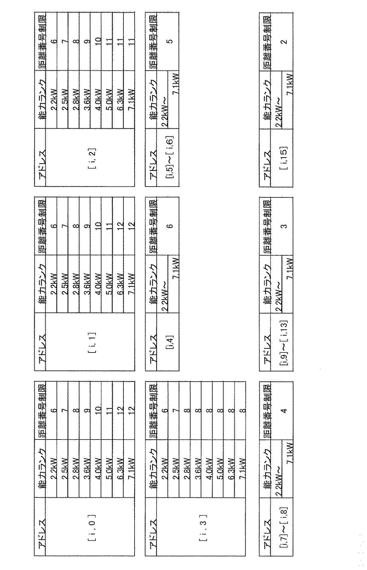


超音波センサ32は、通常その照射方向と対象物の面とのなす角度が90度前後では正確に測定できる反面、その角度が小さくなるにつれて反射波が超音波センサ32に戻って来る確率が徐々に低下し、障害物検知に失敗する可能性が高くなる。
中距離:0.3
遠距離:0.2
また、この障害物検知動作は、空気調和機を運転するたびに行われるので、第2のメモリには、「5」あるいは「-1」が繰り返し加算される。そこで、第2のメモリに記録される数値は、最大値を「10」に、最小値を「0」に設定している。
上記障害物の存否判定に基づき、風向変更手段としての上下羽根12及び左右羽根14は、暖房時次のように制御される。
ブロックR:領域B,E
ブロックC:領域C,F
ブロックL:領域D,G
フィールド1:領域A
フィールド2:領域B,D
フィールド3:領域C
フィールド4:領域E,G
フィールド5:領域F
近距離:領域A
中距離:領域B,C,D
遠距離:領域E,F,G

・高すぎる温度:例えば、56℃以上
・居住者に風を当てない風向制御:居住空間に風を送らないように、上下羽根12を角度制御して、風が天井に沿うように流れる風向制御
・最大風量位置の風向制御:空気調和機は、上下羽根12及び左右羽根14により気流を曲げると必ず抵抗(損失)が発生することから、最大風量位置とは損失が限りなく0に近くなる風向制御(左右羽根14の場合、まっすぐ正面を向いた位置であり、上下羽根12の場合、水平から35度下を向いた位置)
表14は、障害物回避制御を行う場合の上下羽根12の各フィールドにおける目標設定角度を示している。なお、表14における上羽根の角度(γ1)及び下羽根の角度(γ2)は水平線から測定した下向きの角度(俯角)である。


A.上下羽根制御
(1)領域B~Gのいずれかに人がいて、人がいる領域の前方のポジションA1~A3に障害物がある場合
上下羽根12の設定角度を通常のフィールド風向制御(表14)に対し表17のように補正し、上下羽根12を上向き設定した気流制御を行う。

通常自動風向制御を行う。
B.左右羽根制御
B1.領域A(近距離)に人がいる場合
(1)領域Aにおいて障害物のないポジションが一つの場合
障害物のないポジションの目標設定角度を中心として左右にスイング動作させ第1の気流制御を行う。例えば、ポジションA1,A3に障害物があり、ポジションA2に障害物がない場合、ポジションA2の目標設定角度を中心として左右にスイング動作させ、基本的には障害物のないポジションA2を空調するが、ポジションA1,A3に人がいないとは限らないので、スイング動作を加えることで、ポジションA1,A3に多少でも気流が振り分けられるようにする。
障害物のない二つのポジションの目標設定角度を両端としてスイング動作させ第1の気流制御を行うことで、基本的に障害物のないポジションを空調する。
障害物のない二つのポジションの目標設定角度を両端としてブロック停留稼動させ第2の気流制御を行う。
どこを狙っていいのか不明なので、この場合は各ポジションのポジション障害物サイズを参照し、ポジション障害物サイズの小さいポジション二つが隣接している場合は、その二つのポジションの目標設定角度を両端としてスイング動作させ第1の気流制御を行い、離れている場合は、その二つのポジションの目標設定角度を両端としてブロック停留稼動させ第2の気流制御を行う。
領域Aの通常自動風向制御を行う。
(1)人がいる領域に属する二つのポジションの一方にのみ障害物がある場合
障害物のないポジションの目標設定角度を中心として左右にスイング動作させ第1の気流制御を行う。例えば、領域Dに人がいて、ポジションD2にのみ障害物がある場合、ポジションD1の目標設定角度を中心として左右にスイング動作させる。
該当の二つのポジションのポジション障害物サイズを参照し、ポジション障害物サイズの小さいポジションの目標設定角度を中心として左右にスイング動作させ第1の気流制御を行う。例えば、領域Dに人がいて、ポジションD2のポジション障害物サイズの方が大きい場合、ポジションD1の目標設定角度を中心として左右にスイング動作させる。
人がいる領域の通常自動風向制御を行う。
(1)人がいる領域の前方の中距離領域に属する二つのポジションの一方にのみ障害物がある場合(例:領域Eに人がいて、ポジションB2に障害物があり、ポジションB1に障害物がない)
(1.1)障害物があるポジションの両隣に障害物がない場合(例:ポジションB1,C1に障害物がない)
(1.1.1)障害物があるポジションの後方に障害物がない場合(例:ポジションE2に障害物がない)
障害物があるポジションを中心としてポジション停留稼動させ第2の気流制御を行う。例えば、領域Eに人がいて、ポジションB2に障害物があり、その両側にも後方にも障害物がない場合、ポジションB2にある障害物を横から避けて領域Eに気流を送り込むことができる。
中距離領域で障害物がないポジションの目標設定角度を中心としてスイング動作させ第1の気流制御を行う。例えば、領域Eに人がいて、ポジションB2に障害物があり、その両側には障害物がないが、その後方に障害物がある場合、障害物がないポジションB1から気流を送り込むほうが有利である。
障害物がないポジションの目標設定角度を中心としてスイング動作させ第1の気流制御を行う。例えば、領域Fに人がいて、ポジションC2に障害物があり、ポジションC2の両隣のうちポジションD1に障害物があり、C1に障害物がない場合、障害物がないポジションC1からポジションC2の障害物を避けて気流を領域Fに送ることができる。
(2.1)ポジション障害物サイズが大きいポジションの両隣の障害物が小さいあるいはない場合(例:ポジションB1,C1の障害物サイズが小さいあるいはない)
(2.1.1)障害物があるポジションの後方に障害物がない場合(例:ポジションE2に障害物がない)
障害物サイズが大きいポジションを中心としてポジション停留稼動させ第2の気流制御を行う。例えば、領域Eに人がいて、ポジションB2に大きい障害物があり、その両側にも後方にも大きい障害物がない場合、ポジションB2にある大きい障害物を横から避けて領域Eに気流を送り込むことができる。
中距離領域で障害物がないポジションの目標設定角度を中心としてスイング動作させ第1の気流制御を行う。例えば、領域Eに人がいて、ポジションB2に大きい障害物があり、その両側には障害物がないか小さいが、その後方に障害物がある場合、障害物の小さいポジションB1から気流を送り込むほうが有利である。
大きい障害物がないポジションの目標設定角度を中心としてスイング動作させ第1の気流制御を行う。例えば、領域Fに人がいて、ポジションC2に大きい障害物があり、ポジションC2の両隣のうちポジションD1にさらに大きい障害物があり、C1に大きい障害物がない場合、ポジションC1からポジションC2の大きい障害物を避けて気流を領域Fに送ることができる。
(3.1)人がいる領域に属する二つのポジションの一方のポジションにのみ障害物がある場合
障害物がない他方のポジションの目標設定角度を中心としてスイング動作させ第1の気流制御を行う。例えば、領域Fに人がいて、ポジションC1,C2,F1に障害物がなく、ポジションF2に障害物がある場合、人がいる領域Fの前方は開放されているので、遠距離の障害物を考慮して障害物のない遠距離のポジションF1を中心に空調する。
この障害物回避制御は、基本的には障害物検知装置により障害物ありと判定された領域を回避し、障害物なしと判定された領域に向けて送風するためのものであり、以下その具体例を説明する。
A.上下羽根制御
(1)領域A(近距離)に障害物がある場合
暖房時には軽くなって浮き上がる暖気を抑えるために上下羽根12を最下方向に向けて温風を送り出すと、領域Aに障害物がある場合、障害物の裏(室内機側)に暖気がたまったり、暖気が障害物に当たって床面まで届かないことが考えられる。
B.左右羽根制御
(1)領域B,C,D(中距離)のいずれかに障害物がある場合
障害物がないあるいはポジション障害物サイズの小さい方向を重点的に空調する。例えば、領域C(部屋中央)に障害物を検知した場合、あるいは両側よりポジション障害物サイズが大きい場合には、障害物のないあるいはポジション障害物サイズがより小さい両側の領域B,Dを含むブロックを交互にブロック停留稼動させることで、障害物のないあるいは小さい(=人の存在する可能性の高い)領域を重点的に空調できる。
人と壁が同一領域に存在する場合、人は必ず壁よりも前に位置して壁に近接していることになり、暖房時においては、壁近傍に温風が滞留しやすく、壁近傍の室温が他の部分の室温に比べて高くなる傾向にあり、冷房時においては、壁近傍に冷風が滞留しやすく、壁近傍の室温が他の部分の室温に比べて低くなる傾向にあることから、人壁近接制御を行うようにしている。
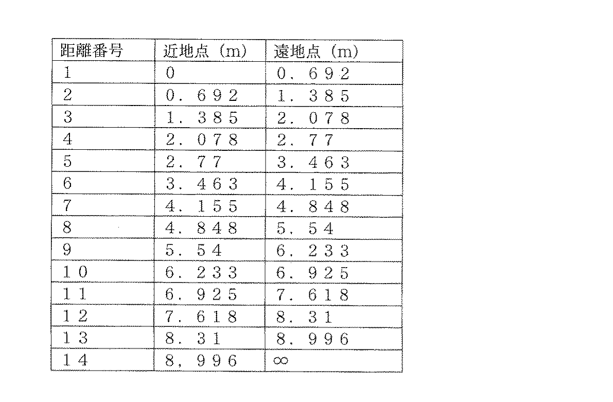
正面:[13,0]~[19,0]、[13,1]~[19,1]、[13,2]~ [19,2]
右端:[31,0]、[32,0]、[31,1]、[32,1]、[31,2]、[32,2]
室内機から左壁WL、正面壁WC、右壁WRまでの距離番号決定に際し、表19に示されるように、まず上記各アドレスで壁面データを抽出する。


A.人が近距離領域あるいは中距離領域にいる場合
近距離領域及び中距離領域は、室内機から近い位置にあり、領域面積も小さいので、室温が上昇する度合いが高くなることから、リモコンで設定された設定温度を第1の所定温度(例えば、2℃)だけ低目に設定する。
B.人が遠距離領域にいる場合
遠距離領域は、室内機から遠い位置にあり、領域面積も大きいので、室温が上昇する度合いは近距離領域あるいは中距離領域より低いことから、リモコンで設定された設定温度を第1の所定温度より少ない第2の所定温度(例えば、1℃)だけ低目に設定する。

なお、障害物の位置決定に際し、デフォルトのマスク時間t1,t2を設定することについては上述したが、左壁WL、正面壁WC、右壁WRまでの距離番号に決定後に行うマスク時間t2の修正について、以下説明する。


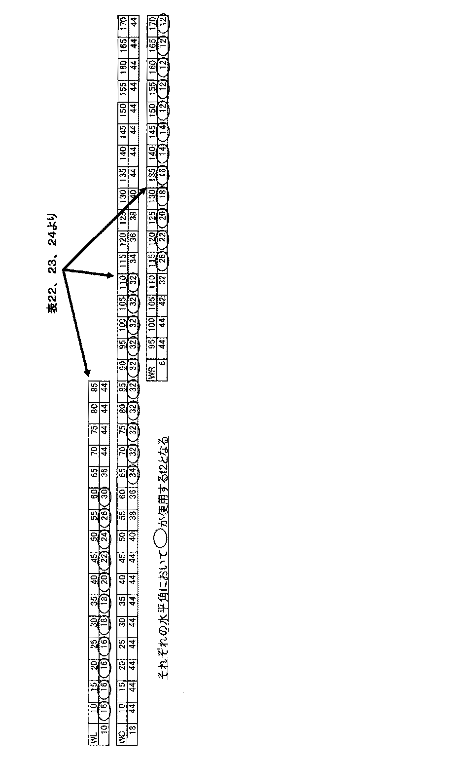
また、壁と障害物では、超音波センサ32が検知する際の俯角が異なることから、壁検知時と障害物検知時とで、超音波センサ32に異なる動きをさせるように制御することで壁と障害物を効率良く正確に検知することができる。
一方、障害物検知時には、遠距離に相当する俯角10度~20度の範囲では、水平方向及び垂直方向をともに5度刻みで次の順番で距離測定を行う。
アドレス[10,1]→アドレス[21,1]→アドレス[21,2]→アドレス[10,2]→アドレス[10,3]→アドレス[21,3]→2回目の遠距離計測終了
アドレス[22,1]→アドレス[32,1]→アドレス[32,2]→アドレス[22,2]→アドレス[22,3]→アドレス[32,3]→最後の遠距離計測終了
また、中距離に相当する俯角15度~30度の範囲では、水平方向及び垂直方向をともに5度刻みで次の順番で距離測定を行う。
アドレス[10,2]→アドレス[21,2]→アドレス[21,3]→アドレス[10,3]→アドレス[10,4]→アドレス[21,4]→アドレス[21,5]→アドレス[10,5]→2回目の中距離計測終了
アドレス[22,2]→アドレス[32,2]→アドレス[32,3]→アドレス[22,3]→アドレス[22,4]→アドレス[32,4]→アドレス[32,5]→アドレス[22,5]→最後の中距離計測終了
さらに、近距離に相当する俯角25度~65度の範囲では、水平方向及び垂直方向をともに10度刻みで次の順番で距離測定を行う。
アドレス[10,4]→アドレス[21,4]→アドレス[21,6]→アドレス[10,6]→アドレス[10,8]→アドレス[21,8]→アドレス[21,10]→アドレス[10,10]→アドレス[10,12]→アドレス[21,12]→2回目の近距離計測終了
アドレス[22,4]→アドレス[32,4]→アドレス[32,6]→アドレス[22,6]→アドレス[22,8]→アドレス[32,8]→アドレス[32,10]→アドレス[22,10]→アドレス[22,12]→アドレス[32,12]→最後の近距離計測終了
すなわち、遠距離に対応する各アドレス(俯角α:10度~20度)及び中距離に対応する各アドレス(俯角α:15度~30度)では垂直方向を5度刻みに走査する一方、近距離に対応する各アドレス(俯角α:25度~65度)では垂直方向を10度刻みに走査することにより、各領域における検知セル数が略等しくなり、壁と障害物の分離検知を効率よく行うことができる。
この壁距離計測は、室内機から正面壁WC、左壁WL、右壁WRの距離番号決定の精度を高めるためのものである。すなわち、室内機は、通常平面視で矩形の部屋の壁面に取り付けられるものとすると、正面壁WC、左壁WL及び右壁WRの位置が分かれば、その位置よりコーナー部の位置が類推できる。コーナー部は略90度の角度をなしており、図29に示されるように、超音波センサ32から送信された超音波の反射波は、必ず送信した方向に戻ってくることから、正確に検知しやすく、実際に測定したコーナー部までの距離と、実際に測定した正面及び左右の壁面WC,WL,WRまでの距離から三角関数によって算出されるコーナー部までの距離を比較することにより、正面及び左右の壁面WC,WL,WRの位置の正確性を確認することができる。この計測は、壁検知の際に照明等を検知して、その照明までの距離を壁面までの距離と誤認識してしまう可能性があることから、コーナー部による確認は非常に重要な役割を果たすものである。

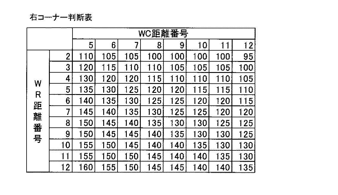


図31は、室内機の設置位置及び部屋形状を認識するためのフローチャートを示している。
Claims (15)
- 室内機に、障害物の有無及び大小を検知する障害物検知装置と、空気の吹き出し方向を左右に変更する左右羽根とを備える空気調和機であって、
前記障害物検知装置による検知結果に基づき、空調すべき領域内に、障害物が存在する障害物領域が複数あり、各障害物領域に存在する障害物の大きさが異なると判断された場合、前記左右羽根を制御して、小さな障害物が存在する障害物領域に向けて空気を吹き出す気流制御を行うことを特徴とする空気調和機。 - 前記左右羽根を揺動させて、小さな障害物が存在する障害物領域に向けて空気を吹き出すことを特徴とする、請求項1に記載の空気調和機。
- 人の在否を検知する人体検知装置をさらに備え、前記人体検知装置及び前記障害物検知装置による検知結果に基づき、空調すべき領域内に、人が存在する人領域と、前記複数の障害物領域がある場合に、前記左右羽根を制御して、小さな障害物が存在する障害物領域に向けて空気を吹き出す気流制御を行うことを特徴とする、請求項1に記載の空気調和機。
- 空調すべき領域を、前記人体検知装置により検知される複数の人位置判別領域に区分するとともに、前記障害物検知装置により検知される複数の障害物位置判別領域に区分し、前記複数の人位置判別領域の各々に少なくとも一つの障害物位置判別領域が属し、前記気流制御が行われるのは、前記人体検知装置により人がいると判定された人位置判別領域に属する障害物位置判別領域あるいは人がいると判定された人位置判別領域の前方に位置する障害物位置判別領域に障害物があると前記障害物検知装置により判定された場合であることを特徴とする、請求項3に記載の空気調和機。
- 前記複数の人位置判別領域の各々が、室内機からの距離に応じて第1の領域及び該第1の領域より遠い第2の領域のいずれかに区分され、前記人体検知装置により人がいると判定された人位置判別領域及び前記障害物検知装置により障害物があると判定された障害物位置判別領域が共に前記第1の領域に属していることを特徴とする請求項4に記載の空気調和機。
- 前記障害物検知装置により障害物がないと判定された障害物位置判別領域が一つの場合、当該一つの障害物位置判別領域を中心にその領域内で前記気流制御を行うことを特徴とする請求項4又は5に記載の空気調和機。
- 前記障害物検知装置により隣接する二つの障害物位置判別領域に障害物がないと判定された場合、前記二つの障害物位置判別領域の中心を両端として前記気流制御を行うことを特徴とする請求項4~6のいずれかに記載の空気調和機。
- 前記障害物検知装置により隣接しない二つの障害物位置判別領域に障害物がないと判定された場合、前記二つの障害物位置判別領域の中心を両端として前記気流制御を行うことを特徴とする請求項4~7のいずれかに記載の空気調和機。
- 前記人体検知装置により人がいると判定された人位置判別領域に属するすべての障害物位置判別領域に障害物があると前記障害物検知装置により判定された場合、障害物がより小さいと判定された障害物判別領域を中心にその領域内で前記の気流制御を行うことを特徴とする請求項4~8のいずれかに記載の空気調和機。
- 前記人体検知装置により人がいると判定された人位置判別領域に二つの障害物位置判別領域が属しており、一方の領域で前記障害物検知装置により障害物があると判定され、他方の領域で障害物がないと判定された場合、前記他方の領域内で前記の気流制御を行うことを特徴とする請求項4~9のいずれかに記載の空気調和機。
- 前記人体検知装置により人がいると判定された人位置判別領域に二つの障害物位置判別領域が属しており、該二つの障害物位置判別領域の両方で前記障害物検知装置により障害物があると判定された場合、人がいると判定された人位置判別領域内で障害物がより小さいと判定された障害物判別領域を中心にその領域内で気流制御を行うことを特徴とする請求項4~10のいずれかに記載の空気調和機。
- 前記複数の人位置判別領域の各々が、室内機からの距離に応じて第1の領域及び該第1の領域より遠い第2の領域のいずれかに区分され、前記人体検知装置により人がいると判定された人位置判別領域が前記第2の領域に属しており、人がいると判定された人位置判別領域に属する二つの障害物判別領域の一方で前記障害物検知装置により障害物がないと判定され、障害物がないと判定された前記一方の障害物判別領域の前方に位置する障害物判別領域に障害物があると判定され、かつ、障害物があると判定された前記障害物判別領域の両側の障害物判別領域のいずれにも障害物がないと判定された場合、前記一方の領域内で前記気流制御を行うことを特徴とする請求項4~11のいずれかに記載の空気調和機。
- 前記複数の人位置判別領域の各々が、室内機からの距離に応じて第1の領域及び該第1の領域より遠い第2の領域のいずれかに区分され、前記人体検知装置により人がいると判定された人位置判別領域が前記第2の領域に属しており、人がいると判定された人位置判別領域に属する二つの障害物判別領域あるいは人がいると判定された人位置判別領域の前方に位置する二つの障害物位置判別領域のうち、一方の領域で前記障害物検知装置により障害物があると判定され、他方の領域で障害物がないと判定された場合、前記他方の領域内で前記気流制御を行うことを特徴とする請求項4~12のいずれかに記載の空気調和機。
- 前記複数の人位置判別領域の各々が、室内機からの距離に応じて第1の領域及び該第1の領域より遠い第2の領域のいずれかに区分され、前記人体検知装置により人がいると判定された人位置判別領域が前記第2の領域に属しており、人がいると判定された人位置判別領域に属する二つの障害物判別領域あるいは人がいると判定された人位置判別領域の前方に位置する二つの障害物位置判別領域の両方で前記障害物検知装置により障害物があると判定された場合、前記二つの障害物位置判別領域内で障害物がより小さいと判定された障害物判別領域を中心にその領域内で気流制御を行うことを特徴とする請求項4~13のいずれかに記載の空気調和機。
- 前記左右羽根が左右それぞれ独立して制御可能な複数枚の左右羽根を備えていることを特徴とする請求項1~14のいずれかに記載の空気調和機。
Priority Applications (2)
| Application Number | Priority Date | Filing Date | Title |
|---|---|---|---|
| CN201080041142.2A CN102575862B (zh) | 2009-09-15 | 2010-07-30 | 空气调节机 |
| BR112012005865-7A BR112012005865A2 (pt) | 2009-09-15 | 2010-07-30 | Condicionador de ar |
Applications Claiming Priority (2)
| Application Number | Priority Date | Filing Date | Title |
|---|---|---|---|
| JP2009212597A JP5267395B2 (ja) | 2009-09-15 | 2009-09-15 | 空気調和機 |
| JP2009-212597 | 2009-09-15 |
Publications (1)
| Publication Number | Publication Date |
|---|---|
| WO2011033714A1 true WO2011033714A1 (ja) | 2011-03-24 |
Family
ID=43758332
Family Applications (1)
| Application Number | Title | Priority Date | Filing Date |
|---|---|---|---|
| PCT/JP2010/004828 WO2011033714A1 (ja) | 2009-09-15 | 2010-07-30 | 空気調和機 |
Country Status (5)
| Country | Link |
|---|---|
| JP (1) | JP5267395B2 (ja) |
| KR (1) | KR20120083334A (ja) |
| CN (1) | CN102575862B (ja) |
| BR (1) | BR112012005865A2 (ja) |
| WO (1) | WO2011033714A1 (ja) |
Families Citing this family (4)
| Publication number | Priority date | Publication date | Assignee | Title |
|---|---|---|---|---|
| KR102138502B1 (ko) * | 2013-06-19 | 2020-07-28 | 엘지전자 주식회사 | 인체감지용 안테나 유닛을 가지는 공기조화장치 |
| JP6552164B2 (ja) * | 2014-07-07 | 2019-07-31 | 日立ジョンソンコントロールズ空調株式会社 | 空気調和機 |
| CN112361557B (zh) * | 2020-11-10 | 2021-10-15 | 珠海格力电器股份有限公司 | 一种空调控制方法、装置、电子设备及可读存储介质 |
| CN112815484B (zh) * | 2021-01-07 | 2022-04-05 | 珠海格力电器股份有限公司 | 热出风的控制方法及控制装置、空调器设备 |
Citations (4)
| Publication number | Priority date | Publication date | Assignee | Title |
|---|---|---|---|---|
| JPH062922A (ja) * | 1992-06-19 | 1994-01-11 | Matsushita Electric Ind Co Ltd | 空気調和システム |
| JP2001355898A (ja) * | 2000-06-15 | 2001-12-26 | Mitsubishi Electric Corp | 空気調和機、壁掛形空気調和機、空気調和機を用いた管理システム |
| WO2008152862A1 (ja) * | 2007-06-12 | 2008-12-18 | Mitsubishi Electric Corporation | 空間認識装置及び空気調和機 |
| JP4524328B2 (ja) * | 2008-12-26 | 2010-08-18 | パナソニック株式会社 | 空気調和機 |
Family Cites Families (1)
| Publication number | Priority date | Publication date | Assignee | Title |
|---|---|---|---|---|
| KR100855000B1 (ko) * | 2007-04-27 | 2008-08-28 | 삼성전자주식회사 | 공기조화기 및 그 제어방법 |
-
2009
- 2009-09-15 JP JP2009212597A patent/JP5267395B2/ja not_active Expired - Fee Related
-
2010
- 2010-07-30 WO PCT/JP2010/004828 patent/WO2011033714A1/ja active Application Filing
- 2010-07-30 KR KR1020127006696A patent/KR20120083334A/ko not_active Application Discontinuation
- 2010-07-30 BR BR112012005865-7A patent/BR112012005865A2/pt not_active Application Discontinuation
- 2010-07-30 CN CN201080041142.2A patent/CN102575862B/zh not_active Expired - Fee Related
Patent Citations (4)
| Publication number | Priority date | Publication date | Assignee | Title |
|---|---|---|---|---|
| JPH062922A (ja) * | 1992-06-19 | 1994-01-11 | Matsushita Electric Ind Co Ltd | 空気調和システム |
| JP2001355898A (ja) * | 2000-06-15 | 2001-12-26 | Mitsubishi Electric Corp | 空気調和機、壁掛形空気調和機、空気調和機を用いた管理システム |
| WO2008152862A1 (ja) * | 2007-06-12 | 2008-12-18 | Mitsubishi Electric Corporation | 空間認識装置及び空気調和機 |
| JP4524328B2 (ja) * | 2008-12-26 | 2010-08-18 | パナソニック株式会社 | 空気調和機 |
Also Published As
| Publication number | Publication date |
|---|---|
| BR112012005865A2 (pt) | 2021-08-31 |
| JP2011064337A (ja) | 2011-03-31 |
| JP5267395B2 (ja) | 2013-08-21 |
| CN102575862A (zh) | 2012-07-11 |
| KR20120083334A (ko) | 2012-07-25 |
| CN102575862B (zh) | 2014-09-10 |
Similar Documents
| Publication | Publication Date | Title |
|---|---|---|
| JP4524328B2 (ja) | 空気調和機 | |
| JP5426235B2 (ja) | 空気調和機 | |
| JP5267408B2 (ja) | 空気調和機 | |
| JP5405901B2 (ja) | 空気調和機 | |
| JP5336931B2 (ja) | 空気調和機 | |
| JP4983882B2 (ja) | 空気調和機 | |
| JP5267395B2 (ja) | 空気調和機 | |
| JP5126189B2 (ja) | 空気調和機 | |
| JP4454683B1 (ja) | 空気調和機 | |
| JP4410301B1 (ja) | 空気調和機 | |
| JP4410302B1 (ja) | 空気調和機 | |
| JP5254881B2 (ja) | 空気調和機 | |
| JP5388726B2 (ja) | 空気調和機 | |
| JP5420302B2 (ja) | 空気調和機 | |
| JP2010276232A (ja) | 空気調和機 | |
| JP5405925B2 (ja) | 空気調和機 | |
| JP4410303B1 (ja) | 空気調和機 | |
| JP4410295B1 (ja) | 空気調和機 | |
| JP4503093B1 (ja) | 空気調和機 | |
| WO2010134283A1 (ja) | 空気調和機および障害物検知装置 | |
| JP5336951B2 (ja) | 空気調和機 | |
| JP2011017459A (ja) | 空気調和機 | |
| JP5426917B2 (ja) | 空気調和機 | |
| JP5249010B2 (ja) | 空気調和機 |
Legal Events
| Date | Code | Title | Description |
|---|---|---|---|
| WWE | Wipo information: entry into national phase |
Ref document number: 201080041142.2 Country of ref document: CN |
|
| 121 | Ep: the epo has been informed by wipo that ep was designated in this application |
Ref document number: 10816829 Country of ref document: EP Kind code of ref document: A1 |
|
| ENP | Entry into the national phase |
Ref document number: 20127006696 Country of ref document: KR Kind code of ref document: A |
|
| NENP | Non-entry into the national phase |
Ref country code: DE |
|
| WWE | Wipo information: entry into national phase |
Ref document number: 2370/CHENP/2012 Country of ref document: IN |
|
| WWE | Wipo information: entry into national phase |
Ref document number: 1201001130 Country of ref document: TH |
|
| 122 | Ep: pct application non-entry in european phase |
Ref document number: 10816829 Country of ref document: EP Kind code of ref document: A1 |
|
| REG | Reference to national code |
Ref country code: BR Ref legal event code: B01A Ref document number: 112012005865 Country of ref document: BR |
|
| ENP | Entry into the national phase |
Ref document number: 112012005865 Country of ref document: BR Kind code of ref document: A2 Effective date: 20120315 |