WO2011030748A1 - プロペラファン、成型用金型および流体送り装置 - Google Patents
プロペラファン、成型用金型および流体送り装置 Download PDFInfo
- Publication number
- WO2011030748A1 WO2011030748A1 PCT/JP2010/065301 JP2010065301W WO2011030748A1 WO 2011030748 A1 WO2011030748 A1 WO 2011030748A1 JP 2010065301 W JP2010065301 W JP 2010065301W WO 2011030748 A1 WO2011030748 A1 WO 2011030748A1
- Authority
- WO
- WIPO (PCT)
- Prior art keywords
- wing
- blade
- propeller fan
- edge portion
- central axis
- Prior art date
Links
Images


Classifications
-
- F—MECHANICAL ENGINEERING; LIGHTING; HEATING; WEAPONS; BLASTING
- F04—POSITIVE - DISPLACEMENT MACHINES FOR LIQUIDS; PUMPS FOR LIQUIDS OR ELASTIC FLUIDS
- F04D—NON-POSITIVE-DISPLACEMENT PUMPS
- F04D29/00—Details, component parts, or accessories
- F04D29/26—Rotors specially for elastic fluids
- F04D29/32—Rotors specially for elastic fluids for axial flow pumps
- F04D29/38—Blades
- F04D29/384—Blades characterised by form
-
- F—MECHANICAL ENGINEERING; LIGHTING; HEATING; WEAPONS; BLASTING
- F04—POSITIVE - DISPLACEMENT MACHINES FOR LIQUIDS; PUMPS FOR LIQUIDS OR ELASTIC FLUIDS
- F04D—NON-POSITIVE-DISPLACEMENT PUMPS
- F04D29/00—Details, component parts, or accessories
- F04D29/26—Rotors specially for elastic fluids
- F04D29/32—Rotors specially for elastic fluids for axial flow pumps
- F04D29/38—Blades
Abstract
Description
[2枚翼のプロペラファンの構造の説明]
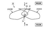
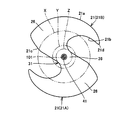
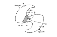
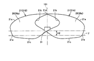
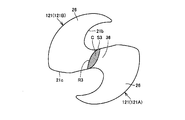
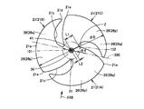
図1は、この発明の実施の形態1における2枚翼のプロペラファンを示す側面図である。図2は、図1中の矢印IIに示す方向(吸込側)から見たプロペラファンを示す平面図である。図3は、図1中の矢印IIIに示す方向(吹出側)から見たプロペラファンを示す平面図である。図4は、図1中のプロペラファンを吸込側から見た斜視図である。
続いて、本実施の形態におけるプロペラファン10によって奏される作用、効果について説明する。
(2)圧力流量特性を向上できるため、ファン性能を向上できる。(近年、たとえば、空気調和機においては、省エネルギー性を向上させるために熱交換器の能力増加に伴い圧力損失が増大する傾向にある。熱交換器の圧力損失が増大すると、風量が低下する(トレードオフの関係)ため、熱交換器の能力増加の効果を十分に得ることができないという課題があった。これに対して、本実施の形態におけるプロペラファン10によれば、圧力流量特性を向上できるため、圧力損失の大きい熱交換器に対しても、風量の低下を抑制でき、その結果、熱交換器の能力増加の効果を十分に得ることができる。)
(3)ファン効率を向上でき、消費電力を低減できる。(近年、たとえば、空気調和機においては、省エネルギー性を向上させるために風量を増加する傾向にある。このため、モータの消費電力が増大するといった問題があった。これに対して、本実施の形態におけるプロペラファン10によれば、風量を増加してもモータの消費電力の増大を抑制できる。風量を増加しない場合には、効率が向上しているため、モータの消費電力を低減できる。)
(4)軽量化により、材料を削減できるとともに、モータの消費電力をさらに低減できる。(ファンの重量が大きいと、モータシャフトのベアリング損失等が増大し、余分な消費電力を必要とする。これに対して、本実施の形態におけるプロペラファン10によれば、ファンを大幅に軽量化でき、その結果、モータシャフトのベアリング損失等を減少できるため、モータの消費電力を低減できる。)
この結果、この発明の実施の形態1におけるプロペラファン10によれば、地球環境保全に対し、省エネルギー性、省資源設計の面で、大きく貢献するプロペラファンを実現することができる。
続いて、図1中のプロペラファン10の構造を適用した3枚翼のプロペラファンの構造について説明する。なお、図1中のプロペラファン10と比較して重複する構造については説明を繰り返さない。
続いて、本実施の形態におけるプロペラファン10,50によって奏される作用、効果を確認するために行なった実施例について説明する。
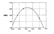
図23を参照して、本実施例では、H(平面γと、翼21Aの前縁部21bおよび翼21Bの後縁部21cの接続部分との間の距離)/D(翼21の周縁部21aの直径D)の値が異なる複数種類のプロペラファンを準備し、一定の回転数で回転させた。各プロペラファンにおける風量を測定し、その測定結果を図23中のグラフにまとめた。本実施例では、直径Dを460mmとし、回転数を1000rpmとした。
図24を参照して、本実施例では、d(仮想円102の直径)/D(翼21の周縁部21aの直径D)が変化するのに伴って、プロペラファンの最大応力がどのように変化するかをシミュレーションにより測定し、その結果を図24中に示すグラフにまとめた。シミュレーションは、中心軸101を中心にプロペラファンを回転させ、遠心力荷重によりプロペラファン全体に作用する応力を求めた。回転数は、1000rpmで一定とし、プロペラファン全体に作用する応力値の中で最も大きい応力を最大応力とした。
本実施の形態では、まず、実施の形態1における各種プロペラファンを樹脂を用いて成型するための成型用金型の構造について説明する。
Claims (12)
- 2枚翼のプロペラファンであって、
周方向に離間して設けられ、仮想の中心軸(101)を中心に回転するのに伴って送風を行ない、2枚翼をなす第1翼(21A)および第2翼(21B)と、
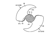
プロペラファンを前記中心軸(101)の軸方向から見て、前記第1翼(21A)および前記第2翼(21B)を周方向に離間させるような最小の仮想円(102)を描いた場合に、その仮想円(102)の内側に配置され、前記第1翼(21A)および前記第2翼(21B)を連接する連接部(31)とを備え、
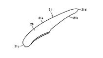
前記第1翼(21A)および前記第2翼(21B)の各翼は、前記中心軸(101)を中心に、直径Dを有して円弧状に延びる周縁部(21a)と、回転方向の側に配置される前縁部(21b)と、回転方向の反対側に配置され、前記周縁部(21a)に連なる後縁部(21c)と、前記前縁部(21b)と前記周縁部(21a)とを接続し、回転方向に向けて突出する翼先端縁部(21d)とを有し、
前記第1翼(21A)の前記前縁部(21b)と前記第2翼(21B)の前記後縁部(21c)とが、前記連接部(31)を通じて接続され、
前記第1翼(21A)および前記第2翼(21B)の、前記後縁部(21c)および前記周縁部(21a)の各交点(21e)を含み、前記中心軸(101)に直交する平面をγと規定し、
プロペラファンを、前記第1翼(21A)および前記第2翼(21B)の前記翼先端縁部(21d)と、前記中心軸(101)とを含む平面(210)に平行な方向から見た場合に、前記中心軸(101)の線上における、前記平面γと、前記第1翼(21A)の前記前縁部(21b)および前記第2翼(21B)の前記後縁部(21c)の接続部分との間の距離Hは、0.028≦H/D≦0.056の関係を満たす、プロペラファン。 - 前記連接部(31)は、前記第1翼(21A)と前記第2翼(21B)との間で延在し、前記第1翼(21A)の根元部および前記第2翼(21B)の根元部を接続する領域に、回転に伴って送風を行なうための翼面状の表面(36)を有する、請求の範囲1に記載のプロペラファン。
- 前記仮想円(102)の直径dは、0.14≦d/Dの関係を満たす、請求の範囲1に記載のプロペラファン。
- 樹脂により成型される、請求の範囲1に記載のプロペラファン。
- 請求の範囲4に記載のプロペラファンを樹脂により成型するために用いられる、成型用金型。
- 請求の範囲1に記載のプロペラファンを備える、流体送り装置。
- 3枚翼のプロペラファンであって、
周方向に離間して設けられ、仮想の中心軸(101)を中心に回転するのに伴って送風を行ない、3枚翼をなす第1翼(21A)、第2翼(21B)および第3翼(21C)と、
プロペラファンを前記中心軸(101)の軸方向から見て、前記第1翼(21A)、前記第2翼(21B)および前記第3翼(21C)を周方向に離間させるような最小の仮想円(102)を描いた場合に、その仮想円(102)の内側に配置され、前記第1翼(21A)、前記第2翼(21B)および前記第3翼(21C)を連接する連接部(31)とを備え、
前記第1翼(21A)、前記第2翼(21B)および前記第3翼(21C)の各翼は、前記中心軸(101)を中心に、直径Dを有して円弧状に延びる周縁部(21a)と、回転方向の側に配置される前縁部(21b)と、回転方向の反対側に配置され、前記周縁部(21a)に連なる後縁部(21c)と、前記前縁部(21b)と前記周縁部(21a)とを接続し、回転方向に向けて突出する翼先端縁部(21d)とを有し、
前記第2翼(21B)は、前記第1翼(21A)に対して回転方向の側に隣接して配置され、前記第3翼(21C)は、前記第2翼(21B)に対して回転方向の側に隣接して配置され、
前記第1翼(21A)の前記前縁部(21b)と、前記第2翼(21B)の前記後縁部(21c)とが、前記連接部(31)を通じて接続され、
前記第1翼(21A)、前記第2翼(21B)および前記第3翼(21C)の、前記後縁部(21c)および前記周縁部(21a)の各交点(21e)を含み、前記中心軸(101)に直交する平面をγと規定し、
プロペラファンを、前記第3翼(21C)の前記翼先端縁部(21d)と、前記中心軸(101)とを含む平面(220)に直角な方向から見た場合に、前記中心軸(101)の線上における、前記平面γと、前記第1翼(21A)の前記前縁部(21b)および前記第2翼(21B)の前記後縁部(21c)の接続部分との間の距離Hは、0.028≦H/D≦0.056の関係を満たす、プロペラファン。 - 前記連接部(31)は、前記第1翼(21A)、前記第2翼(21B)および前記第3翼(21C)のうちの隣接する翼間で延在し、隣接する翼の根元部同士を接続する領域に、回転に伴って送風を行なうための翼面状の表面(36)を有する、請求の範囲7に記載のプロペラファン。
- 前記仮想円(102)の直径dは、0.14≦d/Dの関係を満たす、請求の範囲7に記載のプロペラファン。
- 樹脂により成型される、請求の範囲7に記載のプロペラファン。
- 請求の範囲10に記載のプロペラファンを樹脂により成型するために用いられる、成型用金型。
- 請求の範囲7に記載のプロペラファンを備える、流体送り装置。
Priority Applications (4)
| Application Number | Priority Date | Filing Date | Title |
|---|---|---|---|
| CN201080040194.8A CN102483073B (zh) | 2009-09-11 | 2010-09-07 | 螺旋桨式风扇、成型用模具和流体输送装置 |
| EP10815345.3A EP2476912B1 (en) | 2009-09-11 | 2010-09-07 | Propeller fan, molding die, and fluid feed device |
| US13/395,194 US8926286B2 (en) | 2009-09-11 | 2010-09-07 | Propeller fan, molding die, and fluid feeder |
| KR1020127008985A KR101348012B1 (ko) | 2009-09-11 | 2010-09-07 | 프로펠러 팬, 성형용 금형 및 유체 이송 장치 |
Applications Claiming Priority (2)
| Application Number | Priority Date | Filing Date | Title |
|---|---|---|---|
| JP2009-210295 | 2009-09-11 | ||
| JP2009210295A JP4798640B2 (ja) | 2009-09-11 | 2009-09-11 | プロペラファン、成型用金型および流体送り装置 |
Publications (1)
| Publication Number | Publication Date |
|---|---|
| WO2011030748A1 true WO2011030748A1 (ja) | 2011-03-17 |
Family
ID=43732420
Family Applications (1)
| Application Number | Title | Priority Date | Filing Date |
|---|---|---|---|
| PCT/JP2010/065301 WO2011030748A1 (ja) | 2009-09-11 | 2010-09-07 | プロペラファン、成型用金型および流体送り装置 |
Country Status (6)
| Country | Link |
|---|---|
| US (1) | US8926286B2 (ja) |
| EP (1) | EP2476912B1 (ja) |
| JP (1) | JP4798640B2 (ja) |
| KR (1) | KR101348012B1 (ja) |
| CN (1) | CN102483073B (ja) |
| WO (1) | WO2011030748A1 (ja) |
Cited By (1)
| Publication number | Priority date | Publication date | Assignee | Title |
|---|---|---|---|---|
| EP2642130B1 (en) * | 2012-03-22 | 2019-04-17 | Elica S.p.A. | Impeller for axially conveying fluids, particularly for refrigeration systems |
Families Citing this family (14)
| Publication number | Priority date | Publication date | Assignee | Title |
|---|---|---|---|---|
| MY168508A (en) | 2012-04-10 | 2018-11-12 | Sharp Kk | Propeller fan for electric fan and electric fan including the same, and molding die for propeller fan for electric fan |
| WO2013154102A1 (ja) | 2012-04-10 | 2013-10-17 | シャープ株式会社 | プロペラファン、流体送り装置および成形用金型 |
| CN104088812B (zh) * | 2013-04-01 | 2017-05-17 | 苏州三星电子有限公司 | 一种轴流风扇 |
| JP1530002S (ja) * | 2014-08-11 | 2015-08-03 | ||
| CN107178512A (zh) * | 2017-07-27 | 2017-09-19 | 张兴军 | 螺旋桨式风扇及成型用模具 |
| EP3636337B1 (en) * | 2018-10-12 | 2023-08-16 | Xylem Europe GmbH | Propeller for a digestion tank mixer |
| USD972119S1 (en) * | 2018-11-28 | 2022-12-06 | Ebm-Papst Mulfingen Gmbh & Co. Kg | Fan |
| USD972706S1 (en) * | 2019-02-28 | 2022-12-13 | Ebm-Papst St. Georgen Gmbh & Co. Kg | Ventilating fan |
| USD971398S1 (en) * | 2019-03-04 | 2022-11-29 | Ebm-Papst Mulfingen Gmbh & Co. Kg | Fan wheel of an axial fan |
| USD980409S1 (en) * | 2019-03-07 | 2023-03-07 | Ziehl-Abegg Se | Fan wheel |
| USD972707S1 (en) * | 2019-04-29 | 2022-12-13 | Ebm-Papst Mulfingen Gmbh & Co. Kg | Ventilating fan |
| USD980965S1 (en) * | 2019-05-07 | 2023-03-14 | Carrier Corporation | Leading edge of a fan blade |
| CN110701103B (zh) * | 2019-11-14 | 2020-11-10 | 广东三奇实业发展有限公司 | 一种节能环保磁悬浮鼓风机组装机构 |
| US11821436B2 (en) * | 2021-05-28 | 2023-11-21 | Thermo King Llc | High efficiency axial fan |
Citations (9)
| Publication number | Priority date | Publication date | Assignee | Title |
|---|---|---|---|---|
| JPS6383496U (ja) * | 1986-11-19 | 1988-06-01 | ||
| JPS64397A (en) | 1987-03-13 | 1989-01-05 | Nippon Denso Co Ltd | Blower fan |
| JPH0388999A (ja) | 1989-09-01 | 1991-04-15 | Hitachi Ltd | 軸流フアン |
| JPH0667893U (ja) * | 1993-02-25 | 1994-09-22 | カルソニック株式会社 | モータファン |
| JP2000314399A (ja) | 1999-03-03 | 2000-11-14 | Mitsubishi Electric Corp | プロペラファン、プロペラファンの溶融金属成形方法、プロペラファンの溶融金属成形装置 |
| JP2004132211A (ja) | 2002-10-09 | 2004-04-30 | Mitsubishi Electric Corp | 羽根及び送風機 |
| JP2008240526A (ja) | 2007-03-23 | 2008-10-09 | Nippon Densan Corp | モータ、送風ファン及びその製造方法 |
| JP2010101223A (ja) * | 2008-10-22 | 2010-05-06 | Sharp Corp | プロペラファン、流体送り装置および成型金型 |
| JP2010101227A (ja) * | 2008-10-22 | 2010-05-06 | Sharp Corp | プロペラファン、流体送り装置および成型金型 |
Family Cites Families (9)
| Publication number | Priority date | Publication date | Assignee | Title |
|---|---|---|---|---|
| US958599A (en) * | 1909-09-01 | 1910-05-17 | Mansfield Cooksey | Propeller. |
| US1413296A (en) * | 1919-08-16 | 1922-04-18 | Spreekmeester Emanuel | Propeller |
| US3951611A (en) * | 1974-11-14 | 1976-04-20 | Morrill Wayne J | Blank for fan blade |
| JPS55139997A (en) * | 1979-04-20 | 1980-11-01 | Aisin Seiki Co Ltd | Plastic fan for cooling car engine |
| JPH07115381B2 (ja) * | 1991-09-13 | 1995-12-13 | 日本電装株式会社 | 成形用金型および成形品成形方法 |
| US5437541A (en) * | 1993-12-30 | 1995-08-01 | Vainrub; John | Blade for axial fan |
| ATE307268T1 (de) * | 1999-11-25 | 2005-11-15 | Jayden David Harman | Ein- oder mehrblättriger propellerrotor |
| JP4467952B2 (ja) * | 2003-11-10 | 2010-05-26 | 東芝キヤリア株式会社 | プロペラファン、これを用いた空気調和機用室外ユニット |
| JP4749175B2 (ja) * | 2006-02-14 | 2011-08-17 | シャープ株式会社 | プロペラファンと流体送り装置 |
-
2009
- 2009-09-11 JP JP2009210295A patent/JP4798640B2/ja active Active
-
2010
- 2010-09-07 WO PCT/JP2010/065301 patent/WO2011030748A1/ja active Application Filing
- 2010-09-07 KR KR1020127008985A patent/KR101348012B1/ko not_active IP Right Cessation
- 2010-09-07 CN CN201080040194.8A patent/CN102483073B/zh active Active
- 2010-09-07 EP EP10815345.3A patent/EP2476912B1/en active Active
- 2010-09-07 US US13/395,194 patent/US8926286B2/en active Active
Patent Citations (9)
| Publication number | Priority date | Publication date | Assignee | Title |
|---|---|---|---|---|
| JPS6383496U (ja) * | 1986-11-19 | 1988-06-01 | ||
| JPS64397A (en) | 1987-03-13 | 1989-01-05 | Nippon Denso Co Ltd | Blower fan |
| JPH0388999A (ja) | 1989-09-01 | 1991-04-15 | Hitachi Ltd | 軸流フアン |
| JPH0667893U (ja) * | 1993-02-25 | 1994-09-22 | カルソニック株式会社 | モータファン |
| JP2000314399A (ja) | 1999-03-03 | 2000-11-14 | Mitsubishi Electric Corp | プロペラファン、プロペラファンの溶融金属成形方法、プロペラファンの溶融金属成形装置 |
| JP2004132211A (ja) | 2002-10-09 | 2004-04-30 | Mitsubishi Electric Corp | 羽根及び送風機 |
| JP2008240526A (ja) | 2007-03-23 | 2008-10-09 | Nippon Densan Corp | モータ、送風ファン及びその製造方法 |
| JP2010101223A (ja) * | 2008-10-22 | 2010-05-06 | Sharp Corp | プロペラファン、流体送り装置および成型金型 |
| JP2010101227A (ja) * | 2008-10-22 | 2010-05-06 | Sharp Corp | プロペラファン、流体送り装置および成型金型 |
Cited By (1)
| Publication number | Priority date | Publication date | Assignee | Title |
|---|---|---|---|---|
| EP2642130B1 (en) * | 2012-03-22 | 2019-04-17 | Elica S.p.A. | Impeller for axially conveying fluids, particularly for refrigeration systems |
Also Published As
| Publication number | Publication date |
|---|---|
| EP2476912A1 (en) | 2012-07-18 |
| EP2476912B1 (en) | 2018-12-26 |
| CN102483073B (zh) | 2015-04-15 |
| US8926286B2 (en) | 2015-01-06 |
| US20120171042A1 (en) | 2012-07-05 |
| KR101348012B1 (ko) | 2014-01-07 |
| JP2011058449A (ja) | 2011-03-24 |
| KR20120061970A (ko) | 2012-06-13 |
| CN102483073A (zh) | 2012-05-30 |
| EP2476912A4 (en) | 2017-12-13 |
| JP4798640B2 (ja) | 2011-10-19 |
Similar Documents
| Publication | Publication Date | Title |
|---|---|---|
| JP4798640B2 (ja) | プロペラファン、成型用金型および流体送り装置 | |
| JP4388992B1 (ja) | プロペラファン、流体送り装置および成型金型 | |
| EP2383473B1 (en) | Propeller fan | |
| CN100374732C (zh) | 鼓风机叶轮 | |
| WO2010125645A1 (ja) | プロペラファン | |
| WO2018123519A1 (ja) | プロペラファン | |
| JP4388993B1 (ja) | プロペラファン、流体送り装置および成型金型 | |
| CN210290259U (zh) | 叶轮、风机及电机 | |
| JP5697465B2 (ja) | プロペラファン、成型用金型および流体送り装置 | |
| WO2018189931A1 (ja) | 遠心ファン、成型用金型および流体送り装置 | |
| JP5629720B2 (ja) | プロペラファン、流体送り装置および成形用金型 | |
| JP5629721B2 (ja) | プロペラファン、流体送り装置および成形用金型 | |
| JP6068720B2 (ja) | 扇風機またはサーキュレータ用プロペラファン、扇風機またはサーキュレータ、および成形用金型 | |
| JP2018112196A (ja) | プロペラファン | |
| JP2012012942A (ja) | プロペラファン | |
| JP4749175B2 (ja) | プロペラファンと流体送り装置 | |
| AU2011202590B2 (en) | Propeller fan, fluid feeder and molding die | |
| JPH02173395A (ja) | 軸流ファン構造 | |
| JP6088702B2 (ja) | 扇風機またはサーキュレータ用プロペラファン、扇風機またはサーキュレータ、および成形用金型 | |
| JP2013083158A (ja) | 軸流ファンまたは斜流ファン |
Legal Events
| Date | Code | Title | Description |
|---|---|---|---|
| WWE | Wipo information: entry into national phase |
Ref document number: 201080040194.8 Country of ref document: CN |
|
| 121 | Ep: the epo has been informed by wipo that ep was designated in this application |
Ref document number: 10815345 Country of ref document: EP Kind code of ref document: A1 |
|
| WWE | Wipo information: entry into national phase |
Ref document number: 13395194 Country of ref document: US |
|
| WWE | Wipo information: entry into national phase |
Ref document number: 1201000966 Country of ref document: TH |
|
| NENP | Non-entry into the national phase |
Ref country code: DE |
|
| WWE | Wipo information: entry into national phase |
Ref document number: 2010815345 Country of ref document: EP |
|
| ENP | Entry into the national phase |
Ref document number: 20127008985 Country of ref document: KR Kind code of ref document: A |
|
| WWE | Wipo information: entry into national phase |
Ref document number: 3169/CHENP/2012 Country of ref document: IN |