WO2011027763A1 - アクチュエータ、駆動装置、およびカメラモジュール - Google Patents
アクチュエータ、駆動装置、およびカメラモジュール Download PDFInfo
- Publication number
- WO2011027763A1 WO2011027763A1 PCT/JP2010/064882 JP2010064882W WO2011027763A1 WO 2011027763 A1 WO2011027763 A1 WO 2011027763A1 JP 2010064882 W JP2010064882 W JP 2010064882W WO 2011027763 A1 WO2011027763 A1 WO 2011027763A1
- Authority
- WO
- WIPO (PCT)
- Prior art keywords
- layer
- actuator
- movable
- deformation
- lens group
- Prior art date
- Legal status (The legal status is an assumption and is not a legal conclusion. Google has not performed a legal analysis and makes no representation as to the accuracy of the status listed.)
- Ceased
Links
Images






















Classifications
-
- G—PHYSICS
- G02—OPTICS
- G02B—OPTICAL ELEMENTS, SYSTEMS OR APPARATUS
- G02B7/00—Mountings, adjusting means, or light-tight connections, for optical elements
- G02B7/02—Mountings, adjusting means, or light-tight connections, for optical elements for lenses
- G02B7/028—Mountings, adjusting means, or light-tight connections, for optical elements for lenses with means for compensating for changes in temperature or for controlling the temperature; thermal stabilisation
-
- G—PHYSICS
- G02—OPTICS
- G02B—OPTICAL ELEMENTS, SYSTEMS OR APPARATUS
- G02B7/00—Mountings, adjusting means, or light-tight connections, for optical elements
- G02B7/02—Mountings, adjusting means, or light-tight connections, for optical elements for lenses
- G02B7/04—Mountings, adjusting means, or light-tight connections, for optical elements for lenses with mechanism for focusing or varying magnification
- G02B7/08—Mountings, adjusting means, or light-tight connections, for optical elements for lenses with mechanism for focusing or varying magnification adapted to co-operate with a remote control mechanism
-
- H—ELECTRICITY
- H04—ELECTRIC COMMUNICATION TECHNIQUE
- H04N—PICTORIAL COMMUNICATION, e.g. TELEVISION
- H04N23/00—Cameras or camera modules comprising electronic image sensors; Control thereof
- H04N23/57—Mechanical or electrical details of cameras or camera modules specially adapted for being embedded in other devices
Definitions
- the present invention relates to an actuator, and a drive device and a camera module equipped with the actuator.
- micro camera units In recent years, camera modules are often mounted on small electronic devices such as mobile phones, and so-called micro camera units (MCUs) that have become smaller and thinner have been adopted.
- MCUs micro camera units
- VCM voice coil motor
- AF autofocus
- an actuator using a so-called bi-metal strip can be manufactured in a sheet form.
- a camera module and a heat-driven MEMS (Micro Electro Mechanical Systems) relay to which an actuator using such a bimetal (bimetal actuator) is applied have been proposed (for example, Patent Document 2 and Non-Patent Document 1). ).
- the structure of the sheet-like bimetal actuator described above is easy to apply to the manufacture of MCU at the wafer level.
- the responsiveness that is generally regarded as a problem for the bimetallic actuator, the responsiveness is enhanced because the ratio of the surface area to the volume of the actuator is improved by downsizing. Therefore, it can be said that the bimetal actuator is suitable for use in the MCU.
- the displacement continuously changes as the temperature changes, and the generation amount of the driving force also changes continuously.
- the MCU that moves the optical lens by the bimetal actuator there is a problem that the optical lens moves according to the temperature (environment temperature) in which the MCU is used, and the desired optical conditions cannot be obtained. obtain. That is, it can be said that the accuracy related to driving of the actuator is poor.
- Non-Patent Document 1 since heat insulating portions that suppress heat transfer are provided at both ends of a movable portion having a bimetal, the responsiveness during cooling of the bimetal is low and the environmental temperature is low. No consideration is given to the problem that the optical lens moves in response to this. Moreover, in the technique of the above-mentioned Patent Document 2, when the bimetal reaches a certain temperature or more, the configuration is adopted in which the optical lens moves by being deformed so that the bimetal is reversed, so that the optical lens moves according to the environmental temperature. However, the position of the optical lens cannot be changed continuously, and the degree of freedom in driving the actuator is low.
- a space for example, in the temperature range of the environmental temperature in which the MCU is used, a space (idling space) is provided between the displacement portion of the actuator and the optical lens so that the displacement portion of the actuator does not contact the optical lens.
- a space in which the optical lens is held at a predetermined position by an external force (biasing force) larger than the maximum value of the force that can be applied to the optical lens by the bimetal actuator in the temperature range of the environmental temperature in which the MCU is used is conceivable.
- biasing force biasing force
- the temperature rise is relatively small in the vicinity of the portion (the portion on the root side) fixed to another member of the bimetallic actuator during heating.
- a portion of the actuator between the base portion and the displacement portion is displaced in a direction opposite to the direction in which the displacement portion is displaced, resulting in a decrease in the displacement amount of the displacement portion.
- Generation of such an unnecessary displacement causes an increase in energy consumption for causing a desired displacement in the displacement portion of the actuator.
- Such a problem is remarkably manifested, for example, by reducing the thickness of the actuator for the purpose of improving responsiveness.
- the present invention has been made in view of the above problems, and an actuator capable of reducing energy consumption while ensuring response performance and freedom of driving, and a driving device equipped with the actuator and An object is to provide a camera module.
- the actuator according to the first aspect is fixed at least one end of a movable portion having a displacement portion that is deformed according to a temperature change and is displaced according to the deformation.
- the reference portion and the reference portion that are fixed to the reference portion, and the deformation of the movable portion that is fixed to the reference portion from one end to the middle of the other end is suppressed in accordance with the temperature change.
- a deterrence unit a deterrence unit.
- the said movable part has a heater part which generate
- An actuator according to a second aspect is the actuator according to the first aspect, wherein the movable part includes a first layer and a second layer having a larger coefficient of thermal expansion than the first layer. Are stacked.
- the actuator according to a third aspect is the actuator according to the second aspect, wherein the plurality of layers include a third layer having a thermal conductivity larger than that of the first layer and the second layer, and the reference
- the heat dissipation part includes a heat conduction part having a structure integral with the third layer or in contact with the third layer, and having a thermal conductivity higher than that of the first layer and the second layer. Has a region.
- An actuator according to a fourth aspect is the actuator according to the first aspect, wherein the movable part has a base part, and a shape memory alloy is disposed separately from the heater part to the base part. Configured.
- An actuator according to a fifth aspect is the actuator according to the first aspect, wherein the movable portion has a base portion, the heater portion is configured using a shape memory alloy, and the base portion It arrange
- the actuator according to the sixth aspect is the actuator according to any one of the first to fifth aspects, and the reference portion and the suppression portion are made of the same member.
- the actuator according to the seventh aspect is the actuator according to any one of the first to sixth aspects, and the suppression unit is configured using a material having heat insulation properties.
- the actuator according to the eighth aspect is the actuator according to the seventh aspect, wherein the suppression portion is made of a material having higher heat insulation than the material constituting the movable portion.
- the actuator according to a ninth aspect is the actuator according to any one of the first to eighth aspects, wherein the restraining portion is displaced in response to heating with respect to the position of the movable portion. It is provided at a position in the direction of
- the actuator according to a tenth aspect is the actuator according to any one of the first to ninth aspects, wherein the restraining part is displaced in response to heating with reference to the position of the movable part. It is provided at a position in a direction opposite to the direction in which it is performed.
- the actuator according to the eleventh aspect is the actuator according to the ninth or tenth aspect, in which the suppression portion abuts against the movable portion.
- the actuator according to a twelfth aspect is the actuator according to the ninth or tenth aspect, in which the suppression portion is joined to the movable portion.
- the actuator according to a thirteenth aspect is the actuator according to the twelfth aspect, in which the suppression portion is joined to the movable portion via a material having heat insulation properties.
- a drive device includes the actuator according to any one of the first to thirteenth aspects, and a moving object that is moved by the displacement of the displacement portion.
- a camera module includes an actuator according to any one of the first to thirteenth aspects, an image sensor, and an optical system that guides light from a subject to the image sensor.
- the camera module at least one of the image sensor and the optical system is moved by the displacement of the displacement portion.
- the presence of the restraining portion reduces the amount of energy used when causing a desired displacement, thus ensuring response performance and freedom of driving.
- energy consumption can be reduced.
- the actuator of the second aspect when there is no deterrence part, there is a tendency that unnecessary displacement due to variations in temperature distribution tends to occur, whereas for example, the occurrence of unnecessary displacement is suppressed. , Energy consumption can be greatly reduced.
- the actuator according to the third aspect when there is no deterrence part, there is a tendency that unnecessary displacement due to variation in temperature distribution tends to occur due to the existence of the heat dissipation region, whereas, for example, unnecessary displacement
- the energy consumption can be further reduced while improving the response performance.
- the actuator according to the fourth aspect it is possible to suppress the occurrence of unnecessary displacement due to variations in temperature distribution.
- the actuator according to the fifth aspect it is possible to reduce the manufacturing cost and save resources by simplifying the structure.
- the manufacturing cost can be reduced by simplifying the structure.
- the actuator according to the ninth aspect it is possible to suppress the occurrence of unnecessary displacement according to changes in the environmental temperature.
- the actuator of the tenth aspect it is possible to suppress the occurrence of unnecessary displacement due to variations in temperature distribution.
- the actuator of the twelfth aspect it is possible to suppress the generation of both an unnecessary displacement according to a change in environmental temperature and an unnecessary displacement due to a variation in temperature distribution.
- the actuator according to the thirteenth aspect it is possible to increase the degree of freedom of the material constituting the suppression unit.
- the drive device in the configuration for moving the moving object, it is possible to reduce the energy consumption while ensuring the response performance and the degree of freedom of driving.
- the camera module of the fifteenth aspect in the configuration in which at least one of the image sensor and the optical system is moved, it is possible to reduce energy consumption while ensuring response performance and freedom of driving. it can.
- FIG. 1 is a schematic diagram showing a schematic configuration of a mobile phone equipped with a camera module according to the first and second embodiments.
- FIG. 2 is a schematic cross-sectional view focusing on the first housing according to the first and second embodiments.
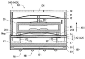
- FIG. 3 is a schematic cross-sectional view of the camera module according to the first and second embodiments.
- FIG. 4 is a schematic side view of the camera module according to the first and second embodiments.
- FIG. 5 is a schematic side view of the camera module according to the first and second embodiments.
- FIG. 6 is a schematic cross-sectional view of the lens group.
- FIG. 7 is a schematic cross-sectional view of the lens group.
- FIG. 8 is an external view of the first lens component layer as viewed from below.
- FIG. 8 is an external view of the first lens component layer as viewed from below.
- FIG. 9 is an external view of the second lens component layer as viewed from above.
- FIG. 10 is a diagram for explaining the shape of the spacer layer.
- FIG. 11 is an external view of the lens position adjustment layer as viewed from above.
- FIG. 12 is a schematic cross-sectional view of the lens position adjusting layer.
- FIG. 13 is an external view of the driving force generation layer as viewed from above.
- FIG. 14 is an external view of the driving force generation layer as viewed from the side.
- FIG. 15 is a diagram for explaining the layer structure of the driving force generation layer.
- FIG. 16 is a diagram showing the shape of the high thermal expansion layer constituting the driving force generation layer.
- FIG. 17 is a diagram showing the shape of the heat conductive layer constituting the driving force generation layer.
- FIG. 18 is a diagram showing the shape of the low thermal expansion layer constituting the driving force generation layer.
- FIG. 19 is a diagram showing the shape of the insulating layer constituting the driving force generation layer.
- FIG. 20 is a diagram showing the shape of the heater layer constituting the driving force generation layer.
- FIG. 21 is a top external view showing the detailed configuration of the driving force generation layer.
- FIG. 22 is a diagram for explaining a mode in which the movable portion generates a driving force.
- FIG. 23 is a diagram for explaining a mode in which the movable portion generates a driving force.
- FIG. 24 is a top view of the deformation suppression layer.
- FIG. 25 is a top view of the actuator layer.
- FIG. 26 is an external view of the second parallel spring as viewed from below.
- FIG. 27 is a diagram illustrating the second parallel spring attached to the lens group.
- FIG. 28 is an external view of the first parallel spring as viewed from below.
- FIG. 29 is a diagram illustrating a first parallel spring attached to the lens group.
- FIG. 30 is a diagram conceptually showing a mechanism for moving the lens group in the camera module not provided with the deformation suppression layer.
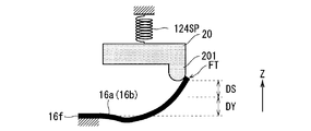
- FIG. 31 is a conceptual diagram showing a state in which the lens group is displaced in accordance with a change in environmental temperature.
- FIG. 32 is a conceptual diagram showing an aspect in which an empty swing space is provided.
- FIG. 33 is a conceptual diagram showing a state in which the lens group is displaced in response to heating.
- FIG. 34 is a diagram showing a temperature distribution in the movable part.
- FIG. 34 is a diagram showing a temperature distribution in the movable part.
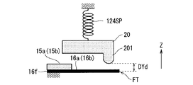
- FIG. 35 is a diagram conceptually showing a mechanism for moving the lens group in the camera module according to the first embodiment.
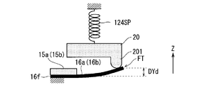
- FIG. 36 is a conceptual diagram illustrating a state in which the lens group is displaced in accordance with a change in environmental temperature in the camera module according to the first embodiment.
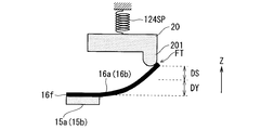
- FIG. 37 is a conceptual diagram showing a state in which the lens group is displaced in response to heating in the camera module according to the first embodiment.
- FIG. 38 is a flowchart showing the manufacturing process of the camera module.
- FIG. 39 is a diagram schematically illustrating a state in which prepared sheets and the like are stacked and joined.
- FIG. 40 is a conceptual diagram illustrating a state in which the lens group is displaced in accordance with a change in environmental temperature in the camera module according to the second embodiment.
- FIG. 41 is a conceptual diagram illustrating a state in which the lens group is displaced in response to heating in the camera module according to the second embodiment.
- FIG. 42 is a diagram conceptually showing a mechanism for moving the lens group in the camera module according to the first modification.
- FIG. 43 is a conceptual diagram showing a state in which the lens group is displaced in accordance with a change in environmental temperature in the camera module according to the first modification.
- FIG. 44 is a conceptual diagram illustrating a state in which the lens group is displaced in response to heating in the camera module according to the first modification.
- FIG. 45 is a diagram conceptually showing a mechanism for moving the lens group in the camera module according to the second modification.
- FIG. 46 is a conceptual diagram showing a state in which the lens group is displaced in accordance with a change in environmental temperature in the camera module according to the second modification.
- FIG. 47 is a conceptual diagram showing a state in which the lens group is displaced in response to heating in the camera module according to the second modification.
- FIG. 48 is a diagram conceptually showing a mechanism for moving the lens group in the camera modules according to the third and fourth modified examples.
- FIG. 49 is a conceptual diagram showing a state in which the lens group is displaced in accordance with a change in environmental temperature in the camera modules according to the third and fourth modifications.
- FIG. 50 is a conceptual diagram showing a state in which the lens group is displaced in response to heating in the camera modules according to the third and fourth modified examples.
- FIG. 51 is a diagram collectively illustrating the relationship between the installation mode of the deformation suppression unit and the obtained effect.
- FIG. 52 is a diagram illustrating an aspect in which an image sensor according to a modification is moved.
- FIG. 1 is a schematic diagram showing a schematic configuration of a mobile phone 100 equipped with a camera module 500 according to the first embodiment.
- three axes XYZ orthogonal to each other are appropriately attached in order to clarify the orientation relation.
- the mobile phone 100 is configured as a foldable mobile phone, and includes a first casing 200, a second casing 300, and a hinge part 400.
- Each of the first casing 200 and the second casing 300 has a plate-like substantially rectangular parallelepiped shape and serves as a casing for storing various electronic members.
- the first casing 200 includes a camera module 500 and a display
- the second casing 300 includes a control unit that electrically controls the mobile phone 100 and an operation member such as a button.
- the hinge part 400 connects the 1st housing
- the current supply driver 600, the electric resistance detection unit 700, and the contrast detection unit 800 are mounted on the first casing 200.
- the current supply driver 600 controls the supply of current to the heater layer 165 (FIG. 20 and FIG. 21) of the driving force generation layer 16 constituting the camera module 500.
- the electrical resistance detector 700 detects electrical resistance in the heater layer 165.
- the contrast detection unit 800 detects the contrast of the image signal obtained by the image sensor 191 (FIG. 3) of the camera module 500.
- a focusing control unit 310 is mounted on the second casing 300.
- the focus control unit 310 controls the amount of current supplied to the heater layer 165 via the current supply driver 600 in accordance with the input of signals from the electrical resistance detection unit 700 and the contrast detection unit 800, so that the camera module Auto focus (AF) control for adjusting the in-focus state of 500 is performed.
- AF Auto focus
- FIG. 2 is a schematic cross-sectional view focusing on the first casing 200 of the mobile phone 100.
- the camera module 500 is a small imaging device, so-called micro camera unit, having an XY cross-section of about 5 mm square and a thickness (depth in the Z direction) of about several mm. (MCU).
- FIG. 3 is a schematic cross-sectional view of the camera module 500, and the direction indicated by the arrow AR1 in FIG. 3 corresponds to the + Z direction.
- an arrow AR ⁇ b> 1 indicating a direction corresponding to the + Z direction is appropriately attached in order to clarify the orientation relationship.
- 4 and 5 are side views of the camera module 500 as viewed from the side.
- the camera module 500 includes an optical unit KB in which a lens group 20 as a photographing optical system is movably provided, and an imaging unit PB that acquires a photographed image related to a subject image. Yes.
- the imaging unit PB has a configuration in which, for example, an imaging element layer 19 having an imaging element 191 such as a CMOS sensor or a CCD sensor and a cover glass layer 18 are laminated in this order in the + Z direction.
- the cover glass layer 18 may include a filter layer that cuts infrared rays (IR).
- the optical unit KB includes a lid layer 10, a first frame layer 11, a first parallel spring (upper parallel spring) 12, a second frame layer 13, a second parallel spring (lower parallel spring) 14, a deformation suppression layer 15, a driving force.
- a generation layer 16, a lens position adjustment layer 17, and a lens group 20 are provided.
- the lid layer 10, the first frame layer 11, the first parallel spring 12, the second frame layer 13, the second parallel spring 14, the deformation suppression layer 15, the driving force generation layer 16, the lens position adjustment layer 17, and the lens group 20 are Both are manufactured in a wafer state (at the wafer level). These manufacturing processes will be described later.
- the lens position adjustment layer 17, the driving force generation layer 16, the deformation suppression layer 15, the second parallel spring 14, the second frame layer 13, the first parallel spring 12, the first frame layer 11, and the lid layer 10. are stacked in this order in the + Z direction, and the lens group 20 is held between the second parallel spring 14 and the first parallel spring 12. Then, the first parallel spring 12, the second parallel spring 14, and the driving force generation layer 16 cooperate with each other to move the lens group 20 in the direction along the Z axis.
- the lid layer 10, the first and second frame layers 11 and 13, the lens position adjustment layer 17, the cover glass layer 18, and the imaging element layer 19 serve as a fixing portion for the lens group 20.
- the camera module 500 and the optical unit KB are manufactured in a wafer state (at the wafer level), and four side surfaces thereof (side surfaces parallel to the Z axis in FIGS. 4 and 5) are cut surfaces formed by dicing. ing. And in this cut surface, the laminated structure of the multiple layer which comprises the optical unit KB and the imaging part PB is exposed.
- the lens group 20 is supported by the first and second parallel springs 12 and 14 coupled to the fixed portion. More specifically, the second parallel spring 14 and the deformation suppression layer 15 are provided between the driving force generation layer 16 and the lens group 20 on the ⁇ Z side (side on which the image sensor 191 is disposed) of the lens group 20. Is inserted. Further, a first parallel spring 12 is interposed between the first frame layer 11 and the lens group 20 on the + Z side (the side where the lid layer 10 is disposed) of the lens group 20. That is, the lens group 20 is sandwiched between the first parallel spring 12 and the second parallel spring 14.
- the posture of the lens group 20 is maintained regardless of the movement of the lens group 20, and the optical axis of the lens group 20 is substantially constant. Retained.
- first and second parallel springs 12 and 14 apply a force in a direction opposite to the moving direction of the lens group 20 (that is, the + Z direction) when the lens group 20 as the moving object moves in the + Z direction.
- the lens group 20 is given.
- the direction of the force applied to the lens group 20 by the first and second parallel springs 12 and 14 is the moving direction of the lens group 20 (ie, ⁇ Z Direction).
- the lens group 20 is moved by the elastic force of the first and second parallel springs 12 and 14 from the lens position adjusting layer 17.
- the lens group 20 is also supported by the lens position adjusting layer 17 by being pressed against the upper end surface of the protrusion 172. That is, the first and second parallel springs 12 and 14 function as springs (bias springs) that always apply a pressing force to the lens group 20 in the ⁇ Z direction.
- the lens group 20 is placed at a predetermined position on the most ⁇ Z side of a range (displaceable range) that can be displaced along the Z axis and is stationary.
- the predetermined position is, for example, a position where the focal point of the optical unit KB is arranged on the + Z side surface (hereinafter also referred to as “imaging surface”) on which a large number of pixel circuits are arranged in the imaging element 191. Is set.
- the focal point of the optical unit KB refers to a point where light beams emitted from the optical unit KB gather at one point when parallel light beams enter the optical unit KB from the + Z side.
- the lens group 20 is pressed against the lens position adjusting layer 17 by the elastic force of the first and second parallel springs 12, 14, and thus is strong against the camera module 500. Even when an impact is applied, the posture of the lens group 20 is maintained.
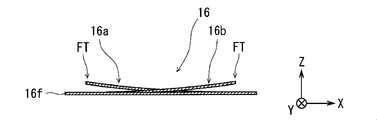
- the driving force generation layer 16 has movable parts 16a and 16b (FIG. 13) that generate driving displacement in the + Z direction, and is disposed on the ⁇ Z side of the lens group 20.
- the movable portions 16a and 16b are in contact with the first protrusion 201 that protrudes toward the ⁇ Z side of the lens group 20, and the drive displacement generated by the movable portions 16a and 16b is transmitted to the lens group 20 via the first protrusion 201. Is done. That is, the driving force generation layer 16 moves the lens group 20 that is a moving object in a predetermined direction (here, the + Z direction). In a scene where the drive displacement in the + Z direction in the movable parts 16a and 16b is reduced, the lens group 20 is moved in the direction opposite to the predetermined direction ( ⁇ Z by the elastic force of the first and second parallel springs 12 and 14). Direction).
- the deformation suppression layer 15 has deformation suppression portions 15a and 15b (FIG. 25) that suppress the drive displacement of the movable portions 16a and 16b in the + Z direction. Due to the presence of the deformation preventing portions 15a and 15b, the movable portions 16a and 16b are deformed in accordance with a change in the environment temperature (environment temperature) in which the camera module 500 is used, and the driving force generation layer 16 is unnecessary. Inconveniences that occur are suppressed. As described above, the driving force generation layer 16 causes a driving displacement by the cooperation of the driving force generation layer 16 and the deformation suppression layer 15. That is, the actuator layer AC is configured by laminating the driving force generation layer 16 and the deformation suppression layer 15.
- the side wiring 21 is a thin conductive member disposed on one of the four side surfaces of the camera module 500. As shown in FIGS. 4 and 5, the side wiring 21 electrically connects the heater layer 165 (FIG. 20), the current supply driver 600, and the electrical resistance detection unit 700 via the imaging element layer 19. . Note that an insulating portion 14ep is provided between the second parallel spring 14 and the side wiring 21 so that the side wiring 21 and the second parallel spring 14 are not short-circuited.
- the lens group 20 that is a moving object is coupled to the first and second parallel springs 12 and 14 disposed at positions facing each other via the lens group 20,
- the first and second parallel springs 12 and 14 are elastically deformed in a direction perpendicular to the lens group 20 (+ Z direction), and hold the posture of the lens group 20.
- the lens group 20 receives a driving force from the movable parts 16a and 16b of the driving force generation layer 16 and displaces its position along the Z axis. Therefore, the optical unit KB provided in the camera module 500 can displace the lens group 20 in the optical axis direction (+ Z direction) of the lens group 20, and the camera module 500 can be used as a driving device for displacing the lens group 20. Make it work.
- the lens group 20 is manufactured at a wafer level using a glass substrate as a base material, and is formed by, for example, superposing two or more lenses. In the present embodiment, a case where the lens group 20 is configured by overlapping two optical lenses is illustrated. In the present embodiment, the lens group 20 functions as an imaging lens that guides light from the subject to the imaging element 191.
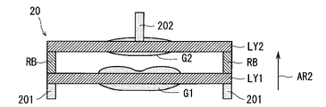
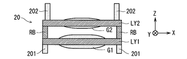
- FIG. 6 and 7 are schematic sectional views of the lens group 20, and the direction indicated by the arrow AR2 corresponds to the + Z direction.
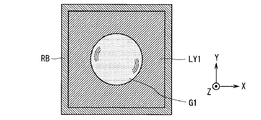
- 8 is a bottom view of the lens group 20 when the lens group 20 is viewed from below ( ⁇ Z side)
- FIG. 9 is a top view of the lens group 20 when the lens group 20 is viewed from above (+ Z side). It is.
- the lens group 20 includes a first lens constituent layer LY1 having a first lens G1, a second lens constituent layer LY2 having a second lens G2, and a spacer layer RB. . Then, the first lens constituent layer LY1 and the second lens constituent layer LY2 are coupled via the spacer layer RB.
- the outer edges of the non-lens portions of the first and second lens constituent layers LY1, LY2 have a substantially square shape.
- the first lens constituting layer LY1 having the first lens G1 has a first main surface (here, ⁇ Z side) on the non-lens portion that does not function as a lens.
- a protrusion 201 is provided.
- a non-lens portion that does not function as a lens is provided on one main surface (here, + Z side) of the second lens constituent layer LY ⁇ b> 2 having the second lens G ⁇ b> 2.
- a second protrusion 202 is provided.
- FIG. 10 is a view of the spacer layer RB as viewed from above (+ Z side) focusing on the shape of the spacer layer RB.
- the spacer layer RB is provided along the outer edge of the non-lens portion of the first and second lens constituting layers LY1 and LY2, and the outer edge and the inner edge of the XY cross section are rectangular in shape. It has a configuration. Then, the optical axis of the lens group 20 is set in a direction along the Z axis.
- each functional layer ⁇ (1-2-3)
- the ⁇ Z side surface is referred to as one main surface
- the + Z side surface is referred to as the other main surface.
- the image sensor layer 19 receives the light from the subject that has passed through the optical unit KB and generates an image signal related to the image of the subject, its peripheral circuit, and the image sensor 191. It is a member provided with the outer peripheral part surrounding.
- the image sensor 191 is configured by arranging a large number of pixel circuits.
- a solder ball HB for performing soldering by a reflow method is provided on one main surface (the surface on the ⁇ Z side) of the imaging element layer 19.
- various terminals for connecting a wiring for applying a signal to the image sensor 191 and reading a signal from the image sensor 191 are provided on one main surface of the image sensor layer 19.
- the current supply driver 600, the electric resistance detection unit 700, and the contrast detection unit 800 are formed on the imaging element layer 19, and the side surface wiring 21 is patterned on the side surface of the camera module 500 cut by dicing.
- the current supply driver 600 and the electric resistance detection unit 700 may be electrically connected to the driving force generation layer 16.
- a focus control unit 310 that controls the operation of the driving force generation layer 16 may be formed in the imaging element layer 19.
- the current supply driver 600, the electrical resistance detection unit 700, and the contrast detection unit 800 are provided, for example, on the circuit board of the second casing 300, and the contrast detection unit 800 captures an image by soldering using a reflow method. While being electrically connected to the element layer 19, the current supply driver 600 and the electric resistance detection unit 700 may be electrically connected to the driving force generation layer 16 via the imaging element layer 19. .
- the cover glass layer 18 has a substantially flat plate shape and an XY cross section having a substantially square shape, and is made of transparent glass or the like.
- the cover glass layer 18 is bonded to the other main surface (+ Z side surface) of the image sensor layer 19 and has a function of protecting the image sensor 191.
- the image sensor substrate 189 is configured with the cover glass layer 18 bonded to the image sensor layer 19.
- the lens position adjustment layer 17 is a member that is configured using a resin material, is disposed between the image sensor 191 and the lens group 20, and adjusts the distance between the image sensor 191 and the lens group 20. Specifically, the lens position adjustment layer 17 defines the position (initial position) of the lens group 20 in the non-driven state.
- the lens position adjustment layer 17 is generated using, for example, a method of etching a resin.
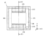
- FIG. 11 is a top view of the lens position adjusting layer 17 when the lens position adjusting layer 17 is viewed from above (+ Z side).
- FIG. 12 is a cross-sectional view of the lens position adjusting layer 17 as seen in the direction of the arrow at the cut surface XII-XII of the lens position adjusting layer 17.
- the lens position adjustment layer 17 includes a frame body 171 and a protrusion 172.
- the frame body 171 is a substantially rectangular annular portion constituting the outer peripheral portion of the lens position adjusting layer 17, and has a plate shape substantially parallel to the XY plane.
- the frame body 171 forms a hole (through hole) 17H penetrating in the direction along the Z axis, and the + Y side plate-like member and the ⁇ Y side plate-like member constituting the frame body 171 are:
- Each plate-like portion has a portion (convex portion) 171T protruding from the lower portion to the through-hole 17H side.
- one main surface of the frame body 171 is bonded to the adjacent cover glass layer 18, and the other main surface of the frame body 171 is connected to the adjacent driving force generation layer 16 (specifically, the driving force generation layer 16 It joins with the frame 16f (FIG. 13).
- the protrusion 172 is erected upward (in the + Z direction) in the vicinity of the inner edge of the protrusion 171T provided on the frame 171.
- the projection 172 is a plate-like portion having a substantially rectangular board surface substantially parallel to the XZ plane, and the longitudinal direction of the projection 172 is a direction substantially parallel to the X axis. Is a direction substantially parallel to the Z-axis.
- the end surface on the + Z side of the protrusion 172 has a function of placing the lens group 20 at the initial position when the lens group 20 abuts.
- an area where a plurality of pixel circuits constituting the image sensor 191 are arranged is indicated by a broken line.
- the protrusion 172 is disposed at a position that sandwiches the optical path from the subject through the lens group 20 to the pixel array region of the image sensor 191 in the direction in which the width of the pixel array region is the narrowest. That is, the protrusion 172 is installed so as not to adversely affect the photographing and increase the size of the apparatus.
- FIG. 13 is a top view of the driving force generation layer 16 as viewed from above (+ Z side).
- FIG. 14 is a side view of the driving force generation layer 16 as viewed from the side.
- FIG. 15 schematically shows the layer structure of the driving force generation layer 16.
- 16 to 20 are diagrams showing the configuration of each layer constituting the driving force generation layer 16.
- the driving force generation layer 16 includes a frame body 16f constituting the outer peripheral portion, and two plate-shaped protrusions projecting from the frame body 16f with respect to a hollow portion inside the frame body 16f.
- Movable parts 16a and 16b are provided. That is, one end of the movable parts 16a and 16b is fixed to the frame 16f as a reference part. Thereby, movable part 16a, 16b comprises the beam part which has what is called a cantilever form.
- One main surface of the frame body 16f is bonded to the adjacent lens position adjustment layer 17 (specifically, the frame body 171), and the other main surface of the frame body 16f is bonded to the adjacent deformation suppression layer 15 ( Specifically, it is joined to the frame 15f (FIG. 24).
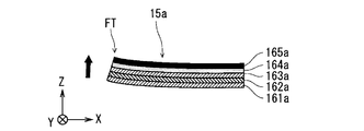
- the driving force generation layer 16 includes a high thermal expansion layer 161 (FIG. 16), a heat conductive layer 162 (FIG. 17), a low thermal expansion layer 163 (FIG. 18), and an insulating layer 164 (FIG. 19).
- the heater layer 165 (FIG. 20) are stacked in this order from the ⁇ Z side to the + Z side. That is, the movable parts 16a and 16b employ so-called bimetal (bi-metallic strip).
- the high thermal expansion layer 161 includes a frame portion 161 f constituting the frame body 16 f, and two plate-like shapes protruding from the frame portion 161 f with respect to a hollow portion inside the frame portion 161 f.
- Protruding portions 161a and 161b are provided.
- the protruding portion 161a constitutes the movable portion 16a
- the protruding portion 161b constitutes the movable portion 16b.
- the high thermal expansion layer 161 is made of a material having a larger coefficient of thermal expansion than the material forming the low thermal expansion layer 163.
- the material constituting the high thermal expansion layer 161 for example, iron-nickel-manganese alloy thermal expansion coefficient is 20 ⁇ 10 -6 / °C, manganese-copper thermal expansion coefficient is 30 ⁇ 10 -6 / °C nickel alloy, any of the thermal expansion coefficient of 18 ⁇ 10 -6 / °C iron-nickel-chromium alloys is, and thermal expansion coefficient of 18 ⁇ 10 -6 / °C iron-molybdenum-nickel alloy is 1 One material is enough. However, the thermal conductivity of these materials is relatively low. For example, the thermal conductivity of an iron / nickel / manganese alloy is about 8.8 W ⁇ m ⁇ 1 ⁇ K ⁇ 1 .
- the heat conductive layer 162 projects from the frame portion 162f to the frame portion 162f constituting the frame body 16f and the hollow portion inside the frame portion 162f, like the high thermal expansion layer 161.
- Two plate-like projecting portions 162a and 162b are provided.
- the protruding portion 162a constitutes the movable portion 16a
- the protruding portion 162b constitutes the movable portion 16b.
- the heat conductive layer 162 is made of a material having a higher thermal conductivity than the material forming the high thermal expansion layer 161 and the low thermal expansion layer 163.
- the material constituting the heat conducting layer 162 for example, copper and copper alloys thermal conductivity of 105.5W ⁇ m -1 ⁇ K -1, heat conductivity in 204W ⁇ m -1 ⁇ K -1 Any one of aluminum and nickel having a thermal conductivity of 90 W ⁇ m ⁇ 1 ⁇ K ⁇ 1 may be used.
- the low thermal expansion layer 163 protrudes from the frame portion 163f with respect to the frame portion 163f constituting the frame body 16f and the hollow portion inside the frame portion 163f, like the high thermal expansion layer 161.
- Two plate-like projecting portions 163a and 163b are provided.
- the protruding portion 163a constitutes the movable portion 16a
- the protruding portion 163b constitutes the movable portion 16b.
- a material constituting the low thermal expansion layer 163 for example, an iron / nickel alloy having a thermal expansion coefficient of 1.1 ⁇ 10 ⁇ 6 / ° C. is preferably employed. However, the thermal conductivity of this material is relatively low, about 8.8 W ⁇ m ⁇ 1 ⁇ K ⁇ 1 .
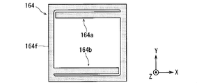
- the insulating layer 164 protrudes from the frame portion 164f with respect to the frame portion 164f constituting the frame body 16f and the hollow portion inside the frame portion 164f, like the high thermal expansion layer 161.
- the protruding portion 164a constitutes the movable portion 16a
- the protruding portion 164b constitutes the movable portion 16b.
- the insulating layer 164 is made of an insulator such as silica (silicon dioxide).
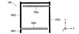
- the heater layer 165 is patterned on the insulating layer 164 and is made of a conductive metal such as platinum having a high resistivity. As shown in FIG. 20, in the heater layer 165, the wiring portion 1651, the heater portion 165b, the wiring portion 1652, the heater portion 165a, and the wiring portion 1653 are extended in this order, and are sequentially electrically connected.
- the wiring portions 1651, 1652, and 1653 constitute the frame body 16f
- the heater portion 165a constitutes the movable portion 16a
- the heater portion 165b constitutes the movable portion 16b.
- the wiring portions 1651, 1652, and 1653 are configured to be wider and have lower electrical resistance than the heater portions 165a and 165b. Therefore, when a voltage is applied between one end of the heater layer 165 (here, the end surface on the ⁇ Y side of the wiring portion 1651) and the other end (here, the end surface on the ⁇ Y side of the wiring portion 1653), The heater parts 165a and 165b having high resistance generate heat due to their own Joule heat. That is, the heater portions 165a and 165b as the heat generating portions generate heat in response to current supply.
- the wiring portions 1651, 1652, and 1653 are preferably made of a metal having a low resistivity such as gold or copper from the viewpoint of reducing power consumption.
- driving force generation layer 16 For the driving force generation layer 16, first, a sheet (driving force generation layer sheet) in which chips corresponding to the driving force generation layer 16 are formed in a predetermined arrangement is generated, and then the driving force generation layer sheet is The driving force generation layer 16 is divided into a shape by a dicing process described later.
- the driving force generation layer sheet is manufactured, for example, by the following process.
- the plate of the material of the high thermal expansion layer 161, the plate of the material of the heat conductive layer 162, and the plate of the material of the low thermal expansion layer 163 are pressed or rolled while being stacked in this order, so that 3 A laminar sheet is created.
- the thin plate having the three-layer structure is cut into a predetermined shape, and a silicon oxide film corresponding to the insulating layer 164 is formed on the thin plate (three-layer thin plate) after the cut by plasma CVD or the like.
- a resist film having a desired pattern by photolithography technology (i) formation of a resist film having a desired pattern by photolithography technology, (ii) formation of a metal film (platinum, copper, gold, etc.) by vapor deposition (or sputtering), etc., and (iii) The removal of unnecessary portions (resist film or the like) by the lift-off method or the like is sequentially performed as appropriate, whereby a wiring pattern corresponding to the heater layer 165 is formed.
- the wiring pattern corresponding to the heater layer 165 may be formed by screen printing or the like.
- the shapes of the movable portions 16a and 16b corresponding to the chips of the driving force generation layers 16, that is, hollow portions are formed by etching or pressing.
- FIG. 21 is a top view showing a detailed configuration of the driving force generation layer 16 when the driving force generation layer 16 is viewed from above (+ Z side).
- the heater layer 165 is formed on the other main surface (+ Z side surface) of the driving force generation layer 16.
- the heater portion 165a extends from one end portion (fixed end) fixed to the frame body 16f of the movable portion 16a to the vicinity of the other end portion (free end) FT of the movable portion 16a. It is folded in the vicinity of the free end FT and extends from the vicinity of the free end FT to the fixed end.
- the heater portion 165b extends from one end portion (fixed end) fixed to the frame body 16f of the movable portion 16b to the vicinity of the other end portion (free end) FT of the movable portion 16b. It is folded near the free end FT and extends from the free end FT to the fixed end. Also, one end of the heater layer 165 (specifically, the end surface on the ⁇ Y side of the wiring portion 1651) and the other end (the end surface on the ⁇ Y side of the wiring portion 1653) are exposed on the side surface of the camera module 500 in the dicing process. To do. A voltage and a current are supplied through the side surface wiring 21 by providing the side surface wiring 21 (FIGS. 3 to 5) to one end and the other end of the exposed heater layer 165.
- FIGS. 22 and 23 are schematic views showing a mode in which the driving force is generated by the deformation of the movable portions 16a and 16b in response to the heat generated by the heater portions 165a and 165b. Since the modes in which the movable parts 16a and 16b generate the driving force are the same, in FIGS. 22 and 23, the mode in which the driving part is generated by the deformation of the movable part 16a is shown as an example. Now, an example in which the driving force is generated by the deformation of the movable portion 16a will be described.
- the deformation of the movable portions 16a and 16b is actually suppressed by the deformation suppression layer 15, but here, first, without considering the suppression of the deformation of the movable portions 16a and 16b by the deformation suppression layer 15, Description will be made by paying attention to generation of driving force due to deformation of the movable parts 16a and 16b.
- production of a driving force are mentioned later.
- the movable portion 16a has a flat plate shape.
- the protruding portion 161a of the high thermal expansion layer 161 expands larger than the protruding portion 163a of the low thermal expansion layer 163 due to heat generated in response to energization to the heater portion 165a.
- the amount of heat generated by the heater 165a exceeds the amount of heat released to the surrounding atmosphere and the frame body 16f via the protruding portion 162a, so that the temperature of the movable portion 16a rises.
- the thickness of the movable portion 16a is made very thin, such as about 30 to 50 ⁇ m, the temperature of the movable portion 16a rises in a relatively short time.
- the movable portion 16a is deformed to warp due to a difference in expansion between the protruding portion 161a and the protruding portion 163a, and above the free end FT (+ Z direction). ) Occurs. That is, the movable portion 16a is deformed according to the temperature change, and the free end FT as the displacement portion is displaced according to the deformation.
- the projecting portions 162a and 162b constituting the movable portions 16a and 16b and the frame portion 162f as the heat conducting portion constituting the frame body 16f are integrally configured, and the heat A conductive layer 162 is formed.
- the heat generation of the heater parts 165a and 165b is finished from the state where the heat of the heater parts 165a and 165b is heated by the heat generation of the heater parts 165a and 165b, Via the frame 16f. At this time, heat is radiated not only from the surfaces of the movable portions 16a and 16b but also from the surface of the frame 16f.
- the frame body 16f is bonded to the deformation suppression layer 15 and the lens position adjustment layer 17 which are functional layers (adjacent layers) adjacent to the driving force generation layer 16 respectively. For this reason, the heat dissipation through the frame 16f and the adjacent layer is promoted, and the cooling rate of the movable parts 16a and 16b is increased. That is, the frame body 16f functions as a region (heat dissipation region) that dissipates heat in order to promote cooling of the movable portions 16a and 16b.
- the heat of the movable parts 16a, 16b is sufficiently absorbed in the heat dissipation area.
- the heat capacity of the frame body 16f is set to be larger than the heat capacity. That is, it is preferable that the volume of the frame body 16f as the heat dissipation region is set to be larger than the volume of the movable portions 16a and 16b.
- the surface area of the frame body 16f is set larger than the surface area of the movable portions 16a and 16b. .
- a heat conductive layer 162 is provided between the high thermal expansion layer 161 and the low thermal expansion layer 163. For this reason, the heat of the high thermal expansion layer 161 and the low thermal expansion layer 163 is easily transmitted to the heat conductive layer 162, and cooling of the movable parts 16a and 16b is promoted. Further, the presence of such a heat conductive layer 162 secures a space between the high thermal expansion layer 161 and the low thermal expansion layer 163, so that the expansion between the projecting portions 161a and 161b and the projecting portions 163a and 163b is achieved. Warpage of the movable parts 16a and 16b due to the difference is promoted. That is, it is possible to increase the displacement of the free end FT with less heating.
- the amount of deformation of the movable portions 16a and 16b is ensured, and the cooling rate of the movable portions 16a and 16b is increased. It is done. That is, response performance can be ensured.
- the thickness of the high thermal expansion layer 161 the thickness of the heat conductive layer 162, and the thickness of the low thermal expansion layer 163 are determined.
- a form having a 2: 1: 2 relationship is preferred.
- FIG. 24 is a top view of the deformation suppression layer 15 as viewed from above (+ Z side).
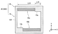
- FIG. 25 is a top view of the actuator layer AC as seen from above (+ Z side) of the actuator layer AC formed by combining the deformation suppressing layer 15 and the driving force generation layer 16.
- the deformation suppression layer 15 is a plate-like member, and the inner side of the frame body 15f from the opposing corners of the frame body 15f constituting the outer peripheral portion and the inner edge of the frame body 15f.
- transformation suppression parts 15a and 15b projected with respect to the hollow part of are provided. That is, the deformation inhibiting portions 15a and 15b are fixed to the frame body 15f as the reference portion.
- the deformation suppressing portion 15a covers the other main surface near the fixed end fixed to the frame body 16f of the movable portion 16a.
- the deformation suppressing portion 15a covers from the + Z side the portion from the fixed end fixed to the frame body 16f to the middle of the free end FT in the movable portion 16a.
- the deformation suppressing portion 15a covers, from the + Z side, a portion of the movable portion 16a corresponding to a section that is about 1/4 of the extension distance in the ⁇ X direction from the fixed end. That is, the ratio of the extension distance L15 along the ⁇ X direction of the deformation suppressing portion 15a and the extension distance L16 along the ⁇ X direction of the movable portion 16a is configured to be about 1: 4. And when the movable part 16a has a flat plate-like shape, it is preferable that the deformation
- the deformation suppressing portion 15a is provided in a space in a direction (here, the + Z direction) in which the free end FT is displaced when the movable portion 16a is heated with reference to the position of the movable portion 16a. For this reason, the deformation
- the deformation suppressing portion 15b covers the other main surface near the fixed end fixed to the frame body 16f of the movable portion 16b.
- the deformation suppressing portion 15b covers from the + Z side the portion from the fixed end fixed to the frame body 16f of the movable portion 16b to the middle of the free end FT.
- the deformation suppressing portion 15b covers, from the + Z side, a portion of the movable portion 16b corresponding to a section that is about 1 ⁇ 4 of the extension distance in the ⁇ X direction from the fixed end. That is, the ratio of the extension distance along the + X direction of the deformation suppressing portion 15b and the extension distance along the + X direction of the movable portion 16b is configured to be about 1: 4. And when the movable part 16b has a flat flat shape, it is preferable that the deformation
- the deformation suppressing portion 15b is provided in a space in a direction (here, the + Z direction) in which the free end FT is displaced when the movable portion 16b is heated with reference to the position of the movable portion 16b. For this reason, the deformation
- the deformation suppressing layer 15 is made of polyimide or the like. For this reason, even if the deformation
- the material constituting the deformation suppressing portions 15a and 15b may be made of a material having higher heat insulation than the material constituting the movable portions 16a and 16b. What is necessary is just to comprise using the material which has heat insulation, such as. The operation of the actuator layer AC will be further described later.
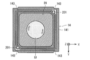
- FIG. 26 is an external view of the lower surface of the second parallel spring 14 when the second parallel spring 14 is viewed from below ( ⁇ Z direction).
- FIG. 27 is a diagram showing the second parallel spring 14 joined to the lens group 20.
- the second parallel spring 14 is an elastic member having a fixed frame body 141 and an elastic portion 142, and is a layer (elastic layer) forming a spring mechanism.
- SUS type metal material or phosphor bronze etc. are employ
- the fixed frame 141 constitutes the outer peripheral portion of the second parallel spring 14 and is joined to the frame 15f of the adjacent deformation suppression layer 15.
- the distance between the heater layer 165 of the driving force generation layer 16 and the second parallel spring 14 is very narrow.
- the side wiring 21 for supplying voltage and current to the heater layer 165 is simply provided from the imaging element layer 19 to the driving force generation layer 16 by printing or the like, the side wiring 21 extends to the fixed frame 141. There is a risk that. That is, the side wiring 21 and the second parallel spring 14 may be short-circuited.
- a notch 143 that is recessed at the outer edge in the vicinity of the four corners of the fixed frame 141 of the second parallel spring 14 is provided.
- the notch 143 is an epoxy used for joining when the second frame layer 13 and the second parallel spring 14 are joined and when the second parallel spring 14 and the deformation suppressing layer 15 are joined.
- An insulating part 14ep (FIGS. 3 to 5) is formed by filling an adhesive such as a resin. Due to the presence of the insulating portion 14ep, unnecessary short circuit due to contact between the side wiring 21 and the second parallel spring 14 is prevented.
- the elastic part 142 has a connection part PG1 with the fixed frame body 141 and a joint part PG2 with the lens group 20, and the connection part PG1 and the joint part PG2 are connected by a plate-like member EB.
- the second parallel spring 14 is joined to the lens group 20 at a joint portion PG ⁇ b> 2 provided in the elastic portion 142.
- the first protrusion 201 contacts the vicinity of the free end FT of the driving force generation layer 16 through the gap between the fixed frame 141 of the second parallel spring 14 and the plate member EB.
- the second parallel spring 14 can be elastically deformed in the optical axis direction ( ⁇ Z direction) of the lens group 20 by elastic deformation of the plate-like member EB, and functions as a spring mechanism.
- the second parallel spring 14 is manufactured using a SUS metal material or phosphor bronze.
- a resist in the shape of a parallel spring is patterned on the metal material by a photolithography technique, and dipped in an iron chloride-based etching solution to be wet. Etching is performed to form a parallel spring pattern.
- the second frame layer 13 is an annular member whose outer edge and inner edge of the XY cross section are each substantially rectangular, and forms a hollow portion that penetrates along the Z axis.
- the second frame layer 13 surrounds the lens group 20 from the side by arranging the lens group 20 in the hollow portion.
- resin, glass, etc. are mentioned as a raw material which comprises the 2nd frame layer 13,
- the 2nd frame layer 13 is manufactured by what is called a press method using a metal metal mold
- the lower end surface (one main surface) located on the ⁇ Z side of the second frame layer 13 is joined to the fixed frame body 141 of the adjacent second parallel spring 14. Further, the upper end surface (other main surface) located on the + Z side of the second frame layer is joined to the adjacent first parallel spring 12 (specifically, the fixed frame body 121 (FIG. 28) of the first parallel spring 12). Is done.
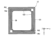
- FIG. 28 is an external view of the lower surface of the first parallel spring 12 when the first parallel spring 12 is viewed from below ( ⁇ Z direction).
- the first parallel spring 12 is an elastic member having the same configuration and function as the second parallel spring 14 except that the notch portion 143 is not provided. 121 and an elastic part 122.
- One main surface of the fixed frame 121 is joined to the other main surface of the adjacent second frame layer 13, and the other main surface of the fixed frame 121 is connected to the adjacent first frame layer 11 (in detail, the first 1 frame layer 11 at the ⁇ Z side lower end surface).
- FIG. 29 is a view showing the first parallel spring 12 joined to the lens group 20.
- the joint portion PG ⁇ b> 2 provided in the elastic portion 122 is joined to the + Z side upper end surface of the protrusion 202 of the lens group 20.
- elastic deformation occurs in the plate-like member EB, and the first parallel spring 12 functions as a spring mechanism.
- the first frame layer 11 is an annular member having an outer edge and an inner edge of the XY cross section that are substantially rectangular, similarly to the second frame layer 13, and penetrates along the Z axis. A hollow part is formed.
- the hollow portion of the first frame layer 11 becomes a space in which the plate-like member EB and the protruding portion 202 that are elastically deformed when the lens group 20 is moved in the + Z direction can move.
- the first frame layer 11 is formed by the same material and manufacturing method as the second frame layer 13.
- the lower end surface (one main surface) located on the ⁇ Z side of the first frame layer 11 is joined to the fixed frame body 121 of the adjacent first parallel spring 12.
- the upper end surface (other end surface) located on the + Z side of the first frame layer is joined to the adjacent lid layer 10 (specifically, near the outer peripheral portion of the lid layer).
- the outer edge of the XY cross section has a substantially square shape
- the lid layer 10 has a hole (through hole) 10 ⁇ / b> H penetrating in a direction parallel to the Z axis at a substantially center, and is substantially in the XY plane. It is a plate-like member having a parallel board surface.
- the through-hole 10H is a hole for guiding light from the subject to the image sensor 191 through the lens group 20, and the lid layer 10 is formed by pressing a flat resin material or by patterning the resin material.
- the through hole 10H is formed and manufactured by a method of etching later.
- FIGS. 30 to 34 are diagrams conceptually showing a mechanism for moving the lens group 20 in the camera module in which the deformation suppression layer 15 is not provided.
- the spring mechanism that is configured by the first and second parallel springs 12 and 14 and applies the force in the ⁇ Z direction to the lens group 20 is simplified as a bias spring 124SP. It is shown.
- the spring mechanism configured by the first and second parallel springs 12 and 14 and applying a force in the ⁇ Z direction to the lens group 20 is appropriately biased. Shown as spring 124SP.
- FIG. 30 shows a state where the movable portion 16a (16b) has a flat plate shape. At this time, the upper surface in the vicinity of the free end FT of the movable portion 16a (16b) is the first portion of the lens group 20. Abuts against the protrusion 201.
- the movable part 16a (16b) employing the bimetal is deformed in proportion to the temperature. For this reason, the movable portion 16a (16b) is deformed in response to a change in the environmental temperature.
- the range of the environmental temperature in which the camera module is used is about ⁇ 20 ° C. to + 70 ° C. in the cellular phone. Accordingly, in the temperature range, for example, when the lens unit 20 moves due to the movable portion 16a (16b) deforming according to a change in the environmental temperature, the lens unit 20 does not stop at a desired position.
- FIG. 31 shows a deformation mode of the movable portion 16a (16b) at the upper limit (here, about 70 ° C.) of the temperature range related to the environmental temperature.
- FIG. 31 shows a state in which the free end FT is displaced by a distance DY in the + Z direction with reference to the state shown in FIG.
- an external force (biasing force) larger than the maximum force that can be applied to the lens group 20 by the movable portion 16a (16b) is applied to the lens group 20 by the bias spring 124SP.
- biasing force larger than the maximum force that can be applied to the lens group 20 by the movable portion 16a (16b) is applied to the lens group 20 by the bias spring 124SP.
- the environmental temperature is low, it is necessary to generate a driving force exceeding the urging force when moving the lens group 20 due to the displacement of the displacement portion of the actuator. For this reason, a great amount of energy is required for heating the bimetal, resulting in an increase in energy consumption.
- FIG. 33 shows a state in which the movable portion 16a (16b) is heated and deformed by energizing the heater layer 165 with reference to the state shown in FIG.
- FIG. 33 shows a state in which the lens group 20 has moved by a distance DS in the + Z direction with reference to the state shown in FIG.
- FIG. 34 is a diagram illustrating an example of a temperature distribution of the movable portion 16a (16b) when the movable portion 16a (16b) is heated by the heater layer 165. As shown in FIG. 34, the temperature rise near the roots of the movable parts 16a and 16b is very small compared to the temperature rise near the free end FT.
- the amount of deformation and driving force generated near the base of the movable portion 16a (16b) is the amount of deformation and driving force generated near the free end FT.
- the biasing spring 124SP applies a pressing force in the ⁇ Z direction in the vicinity of the free end FT, so that in the movable portion 16a (16b), the free end FT is displaced in the region from the fixed end to the central portion.
- a phenomenon (sagging in the middle part) that causes a slight displacement in the direction opposite to the power direction occurs.
- the amount of displacement at the displacement portion here, in the vicinity of the free end FT
- generation of such an unnecessary displacement causes an increase in energy consumption for causing a desired displacement in the displacement portion of the actuator.
- the deformation suppression layer 15 is provided, so that the empty space can be reduced.
- the camera module 500A according to the second embodiment to be described later it is possible to suppress the sagging in the intermediate portion.
- the operation of the actuator layer AC in the camera module 500 according to the first embodiment will be described below.
- FIG. 35 to FIG. 37 are diagrams conceptually showing a mechanism for moving the lens group 20 in the camera module 500 provided with the deformation suppression layer 15.
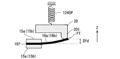
- FIG. 35 shows a state in which the environmental temperature is relatively low and the movable portion 16a (16b) has a flat plate shape. At this time, the upper surface of the movable portion 16a (16b) near the free end FT The distance from the first protrusion 201 of the lens group 20 is DYd.
- FIG. 36 shows a mode of deformation of the movable portion 16a (16b) at the upper limit (here, about 70 ° C.) of the temperature range related to the environmental temperature.
- 36 shows a state where the free end FT is displaced by a distance DYd in the + Z direction with reference to the state shown in FIG.
- the upper surface the surface on the + Z side
- the deformation suppressing portions 15a and 15b It abuts against the (-Z side surface).
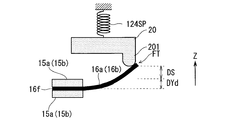
- the deformation suppression portions 15a and 15b suppress the displacement of the portions near the roots of the movable portions 16a and 16b. For this reason, the amount of displacement of the free end FT in the + Z direction is reduced as compared with the configuration in which the deformation inhibiting portions 15a and 15b are not provided (FIG. 31). That is, the relationship of distance DY> distance DYd is established.
- the empty space for coping with the deformation of the movable portions 16a and 16b according to the change of the environmental temperature is reduced.
- the energy consumption required to generate a displacement exceeding the idle swing space at the free end FT is reduced. That is, energy (here, electric power) required for heating the bimetal is reduced.
- FIG. 37 shows a state where the movable portion 16a (16b) is heated and deformed by energizing the heater layer 165 with the state shown in FIG. 35 as a reference.
- FIG. 37 shows a state in which the lens group 20 has moved by a distance DS in the + Z direction with reference to the state shown in FIG.
- a current supply driver 600, an electrical resistance detection unit 700, and a contrast detection unit 800 are mounted on the first casing 200, and the second casing 300 is in focus.
- a control unit 310 is mounted.
- the electrical resistance detector 700 detects the electrical resistance of the heater layer 165 and outputs a signal indicating the electrical resistance to the focus control unit 310.
- the focusing control unit 310 detects the deformation of the movable parts 16a and 16b (specifically, the displacement of the free end FT) based on the electric resistance of the heater layer 165.
- the detection of the displacement of the free end FT is performed by utilizing the fact that the relationship between the shape and the electrical resistance in the heater layer 165 (specifically, the heater portions 165a and 165b) is uniquely determined.
- the focus control unit 310 controls the current supplied to the heater layer 165 via the current supply driver 600 while detecting the displacement of the free end FT, so that the deformation amount of the movable units 16a and 16b, that is, free Control the displacement of the end FT.
- the lens group 20 is moved in the + Z direction, so that the separation distance between the lens group 20 and the image sensor 191 is changed, and the focal point of the optical unit KB. The position of is changed.
- the contrast detection unit 800 detects the contrast of the image signal obtained by the image sensor 191. For example, a numerical value obtained by accumulating differences in gradation values between adjacent pixels for the entire image is detected as an evaluation value indicating contrast. A signal related to the evaluation value indicating the contrast is output to the focus control unit 310.
- the separation distance between the lens group 20 and the image sensor 191 is sequentially set to preset multi-step separation distances under the control of the focus control unit 310, and each separation distance is set.
- An image signal is acquired by the image sensor 191 in the set state.
- the extension position of the lens group 20 in the + Z direction is set to a preset multi-stage position, and an image signal is received by the image sensor 191 at the time when the lens group 20 is arranged at each extension position.
- the focus control unit 310 controls the supply of current to the heater layer 165 via the current supply driver 600 while monitoring the electrical resistance of the heater layer 165 detected by the electrical resistance detection unit 700.
- the extended position of the lens group 20 is changed.
- the focus control unit 310 detects a feeding position where the evaluation value indicating the contrast is maximum based on the evaluation value indicating the contrast detected for each feeding position by the contrast detection unit 800.
- the state where the lens group 20 is disposed at the extended position where the evaluation value indicating the contrast is maximum corresponds to the state where the subject is in focus.
- the lens group 20 is moved to the extended position where the evaluation value indicating the contrast is maximized, thereby achieving focusing on the subject in the camera module 500. That is, AF control is realized.
- the degree of freedom of driving is ensured to the extent that the above-described AF control can be realized.
- FIG. 38 is a flowchart showing the manufacturing process of the camera module 500.
- process A generation of the lens group 20 (step SP1)
- step SP2 sheet preparation
- step SP3 assembly jig preparation
- step SP3 assembly jig preparation
- step SP4 First joining of the sheet
- step SP5 Mounting of the lens group 20
- Step SP6 Second joining of the sheet
- Step SP6 Second joining of the sheet
- Step SP8 Imaging element substrate 189
- step SP8 processing H
- step SP1 the lens group 20 is generated.
- a wafer in which a large number of lens groups 20 are arranged in a matrix (hereinafter also referred to as a “lens group wafer”) is manufactured, and a large number of lens groups 20 are separated into pieces by dicing. Group 20 is produced.
- the lens group wafer includes a wafer in which a large number of first lens constituent layers LY1 are arranged (first lens constituent layer wafer), a wafer in which a large number of spacer layers RB are arranged (spacer layer wafer), and a large number of second lenses.
- a wafer (second lens constituent layer wafer) on which the constituent layers LY2 are arranged is laminated and bonded together.
- step SP2 a sheet relating to each functional layer constituting the camera module 500 is formed for each layer.
- a disc-shaped sheet at the wafer level is prepared.
- a large number of chips corresponding to members related to the functional layer are formed in a matrix on the sheet for each functional layer.
- the lid layer 10 the first frame layer 11, the first parallel spring 12, the second frame layer 13, the second parallel spring 14, the deformation suppression layer 15, the driving force generation layer 16, and the lens
- Each sheet (specifically, a lid layer sheet, a first frame layer sheet, a first parallel spring sheet, a second frame layer sheet, etc.) in which a large number of chips related to each functional layer such as the position adjustment layer 17 are formed in a predetermined arrangement.
- Each of the sheets (imaging element substrate sheets) U189 including the chips is prepared. That is, nine sheets U10 to U189 and U189 are prepared.
- step SP3 Preparation of assembly jig (process C)>
- an assembly jig is prepared.
- the assembling jig is configured by providing a plurality of protrusions having substantially the same shape on a flat base in a predetermined arrangement.
- alignment marks for alignment are formed at two or more predetermined locations.
- the upper surface of the protrusion is configured to be substantially parallel to the main surface of the flat base.
- a unit corresponding to each camera module 500 is manufactured on the upper surface.
- step SP4 Three sheets U11 to U13 among the nine prepared sheets U10 to U189 and U189 are joined.
- the first frame layer sheet U11, the first parallel spring sheet U12, and the second frame layer sheet U13 are aligned in the sheet shape so that the chips included in the sheets U11 to U13 are stacked on each other. (Alignment) is performed. Then, the sheets U11 to U13 are joined using an adhesive or the like.
- FIG. 39 shows a state in which three sheets U11 to U13 are stacked and joined in step S4, a lens group 20 is attached in step S5, and five sheets U10 and U14 to U17 are stacked in step S6. It is a figure which shows typically a mode that it joins, and a mode that the image pick-up element board
- step SP5 the lens group 20 generated in step SP1 is attached to a hollow portion of each second frame layer 13 of the unit manufactured in step SP4 by a predetermined mounter. That is, the lens group 20 is inserted into each gap of the second frame layer sheet U13 having a lattice shape.
- the end surface of the second protrusion 202 is joined to the one main surface side of the joint PG2.
- the method etc. which join using the adhesive agent (UV curing adhesive) hardened
- step SP6 Five sheets U10, U14 to U17 out of the nine sheets U10 to U17 and U189 prepared in step SP2 are joined. Specifically, in step SP6, each of the units included in the second parallel spring sheet U14, the deformation suppression layer sheet U15, and the driving force generation layer sheet U16 with respect to the one main surface side of the units generated up to step SP5. Alignment (alignment) is performed with the sheet shape so that the chips are sequentially stacked on the chips included in the second frame layer sheet U13. Then, the sheets U14 to U16 are sequentially joined using an adhesive or the like.
- the sheet is so formed that each chip included in the lid layer sheet U10 is stacked with respect to each chip included in the first frame layer sheet U11 with respect to the other main surface side of the first frame layer sheet U11. Alignment (alignment) is performed in the shape. In this state, the lid layer sheet U10 is bonded to the other main surface side of the first frame layer sheet U11 using an adhesive or the like.
- each chip included in the lens position adjustment layer sheet U17 is laminated on each chip included in the driving force generation layer sheet U16 on one main surface side of the driving force generation layer sheet U16. Then, alignment (alignment) is performed in the sheet shape. In this state, the lens position adjustment layer sheet U17 is bonded to one main surface side of the driving force generation layer sheet U16 using an adhesive or the like.
- step SP7 the lens is arranged so that the outer peripheral portion of the image sensor substrate 189 is bonded to the frame body 171 of the lens position adjusting layer 17 of the unit formed by bonding the lens position adjusting layer 17 until step SP6.
- the other main surface of the imaging element substrate sheet U189 is bonded to one main surface of the position adjustment layer sheet U17.
- step SP8 a large number of lens groups 20 are inserted, and the laminated member formed by laminating the nine sheets U10 to U17 and U189 is protected by a dicing tape or the like and then separated for each chip by a dicing device. .
- a large number of camera modules 500 are completed.
- the side wiring 21 is formed. Specifically, when dicing along one direction is performed, each heater layer 165 is exposed at a cut surface corresponding to the side surface of each camera module 500. Therefore, a conductive material for forming the side wiring 21 is applied to the cut surface, and then dicing along the other direction is performed, so that a large number of camera modules 500 are completed.
- the amount of energy used when a desired displacement is generated is reduced due to the presence of the deformation suppressing portions 15a and 15b in the actuator layer AC. Therefore, the energy consumption can be reduced while ensuring the response performance and the degree of freedom of driving.
- the deformation suppressing portions 15a and 15b are provided at positions in the direction in which the free end FT is displaced in response to heating with the positions of the movable portions 16a and 16b as a reference. For this reason, generation
- the material constituting the deformation suppressing portions 15a and 15b is constituted by using a heat insulating material such as polyimide. Furthermore, the material constituting the deformation suppressing portions 15a and 15b is made of a material having higher heat insulation than the material constituting the movable portions 16a and 16b. With such a configuration, unnecessary displacement such as sagging in the intermediate portion is less likely to occur due to heat transfer from the movable portions 16a and 16b to the deformation suppressing portions 15a and 15b.
- the deformation suppression portions 15a and 15b suppress the displacement of the portions near the roots of the movable portions 16a and 16b according to changes in the environmental temperature, thereby reducing the empty swing space. As a result, energy consumption was reduced.
- the deformation suppression portions 15a and 15b are joined to the portions near the roots of the movable portions 16a and 16b, as shown in FIG. Occurrence of sagging in the intermediate portion is suppressed.
- the actuator layer AC of the camera module 500 according to the first embodiment has the deformation suppression portion 15a and the movable portion 16a joined together and the deformation suppression portion 15b and the movable portion.
- the actuator layer ACA is joined to 16b.
- the first casing 200 and the mobile phone 100 are changed to the first casing 200A and the mobile phone 100A.
- the actuator layer ACA shown in FIGS. 3 and 25 includes one main surface (surface on the ⁇ Z side) of the deformation suppressing portion 15a and a portion near the base of the movable portion 16a.
- the main surface (+ Z side surface) is joined, and one main surface ( ⁇ Z side surface) of the deformation suppressing portion 15b and the other main surface (+ Z side surface) near the root of the movable portion 16b Are joined together.
- the joining method include a method using an adhesive such as a resin.
- 40 and 41 are diagrams conceptually showing a mechanism for moving the lens group 20 in the camera module 500A.
- the mechanism for moving the lens group 20 is the same as that in the first embodiment shown in FIG. It will be as shown.
- FIG. 40 shows a mode of deformation of the movable portion 16a (16b) at the upper limit (here, about 70 ° C.) of the temperature range related to the environmental temperature. 40 shows a state where the free end FT is displaced by a distance DYd in the + Z direction with reference to the state shown in FIG.
- the deformation restraining parts 15a and 15b cause the portions near the roots of the movable parts 16a and 16b. Displacement is suppressed.
- the amount of displacement of the free end FT in the + Z direction is reduced as compared with the configuration in which the deformation inhibiting portions 15a and 15b are not provided (FIG. 31). Therefore, the energy (here, electric power) required for heating the bimetal is reduced due to the reduction of the idling space.
- FIG. 41 shows a state where the movable portion 16a (16b) is heated and deformed by energization of the heater layer 165 with reference to the state shown in FIG. 41 shows a state in which the lens group 20 has moved by a distance DS in the + Z direction with reference to the state shown in FIG.
- the deformation restraining portions 15a and 15b and the portions near the roots of the movable portions 16a and 16b are joined. Therefore, as shown in FIG. Is suppressed. Accordingly, since unnecessary deformation hardly occurs in the movable portions 16a and 16b, the bending of the movable portions 16a and 16b efficiently leads to the displacement of the free end FT. As a result, the power required to cause the lens group 20 to move the distance DS in the + Z direction on the basis of the state shown in FIG. 35 can be reduced.
- the deformation suppression portions 15a and 15b are joined to the portions near the roots of the movable portions 16a and 16b.
- the actuator layer ACA using bimetal if the deformation suppressing portions 15a and 15b are not present, unnecessary displacement due to variations in temperature distribution tends to occur. Furthermore, in the configuration of the actuator layer ACA provided with the heat dissipation area, unnecessary displacement due to variations in temperature distribution tends to occur. On the other hand, according to the configuration of the actuator layer ACA according to the present embodiment, the occurrence of unnecessary displacement is suppressed, and the energy consumption is significantly reduced.
- the deformation suppression layer 15 is provided on the other main surface side of the driving force generation layer 16, but the present invention is not limited to this.
- an aspect in which the deformation suppression layer 15 is provided on one main surface side of the driving force generation layer 16 is also conceivable.
- a mode in which the deformation suppression layer 15 is provided between the driving force generation layer 16 and the lens position adjustment layer 17 can be considered.
- the other main surfaces of the deformation suppression portions 15a and 15b of the deformation suppression layer 15 provided on the one main surface side of the driving force generation layer 16 are joined to one main surface of the portion near the root of the movable portions 16a and 16b.
- the embodiment to be considered is also possible. Specifically, for example, the following four modes (I) to (IV) can be considered.
- the deformation suppression layer 15 is provided between the driving force generation layer 16 and the lens position adjustment layer 17.
- the driving force generation layer 16 and the deformation suppression layer 15 provided on one main surface side constitute an actuator layer.
- the deformation suppression layer 15 is provided between the driving force generation layer 16 and the lens position adjustment layer 17.
- the driving force generation layer 16 and the deformation suppression layer 15 provided on one main surface side of the driving force generation layer 16 constitute an actuator layer.
- a deformation suppression layer 15 is provided between the driving force generation layer 16 and the second parallel spring 14, and a deformation suppression layer 15 is further provided between the driving force generation layer 16 and the lens position adjustment layer 17.
- the driving force generation layer 16 and the two deformation suppression layers 15 provided on the upper and lower sides thereof constitute an actuator layer.
- a deformation suppression layer 15 is provided between the driving force generation layer 16 and the second parallel spring 14, and a deformation suppression layer 15 is further provided between the driving force generation layer 16 and the lens position adjustment layer 17.
- the driving force generation layer 16 and the two deformation suppression layers 15 provided on the upper and lower sides thereof constitute an actuator layer.
- a deformation suppression layer 15 is provided between the driving force generation layer 16 and the second parallel spring 14, and a deformation suppression layer 15 is further provided between the driving force generation layer 16 and the lens position adjustment layer 17.
- a mode is also conceivable in which one main surface of the portions near the roots of the movable portions 16a and 16b and one main surface of the other main surfaces are joined to the deformation suppressing portions 15a and 15b.
- the effect obtained by this aspect is the same as the effect obtained by the above aspect (IV).
- First Modification> 42 to 44 are diagrams conceptually showing a mechanism for moving the lens group 20 in the camera module according to the first modification.
- FIG. 42 shows a state in which the environmental temperature is relatively low and the movable portion 16a (16b) has a flat plate shape. At this time, the upper surface of the movable portion 16a (16b) near the free end FT The distance from the first projection 201 of the lens group 20 is DY.
- 43 shows a mode of deformation of the movable portion 16a (16b) at the upper limit (here, about 70 ° C.) of the temperature range related to the environmental temperature. 43 shows a state in which the free end FT is displaced by a distance DY in the + Z direction with reference to the state shown in FIG.
- the movable parts 16a and 16b do not contact the deformation inhibiting parts 15a and 15b, the presence of the deformation inhibiting parts 15a and 15b in particular does not affect the deformation of the movable parts 16a and 16b.
- FIG. 44 shows a state in which the movable portion 16a (16b) is heated and deformed by energizing the heater layer 165 with reference to the state shown in FIG. 44 shows a state in which the lens group 20 has moved by a distance DS in the + Z direction with reference to the state shown in FIG.
- the deformation suppressing portions 15a and 15b are provided on the one main surface side of the portions near the roots of the movable portions 16a and 16b.
- the deformation inhibiting portions 15a and 15b are in a direction (here, ⁇ Z) opposite to the direction (here, the + Z direction) in which the free end FT is displaced in response to heating with respect to the positions of the movable portions 16a and 16b. (Z direction).
- the deformation suppression portions 15a and 15b suppress the displacement of the portions near the roots of the movable portions 16a and 16b. For this reason, as shown in FIG. 44, as compared with the configuration in which the deformation inhibiting portions 15a and 15b are not provided (FIG. 33), unnecessary displacement (specifically, in the intermediate portion) in the movable portions 16a and 16b. Occurrence of drooping) is suppressed.
- FIG. 45 shows a state in which the environmental temperature is relatively low and the movable portion 16a (16b) has a flat plate shape. At this time, the upper surface of the movable portion 16a (16b) near the free end FT The distance from the first protrusion 201 of the lens group 20 is DYd.
- FIG. 46 shows a mode of deformation of the movable portion 16a (16b) at the upper limit (here, about 70 ° C.) of the temperature range related to the environmental temperature. 46 shows a state in which the free end FT is displaced by a distance DYd in the + Z direction with reference to the state shown in FIG.
- the deformation restraining portions 15a and 15b and the portions near the roots of the movable portions 16a and 16b are joined, as shown in FIG. 46, the deformation restraining portions 15a and 15b cause the movable portions 16a and 16b to move. Displacement near the root is suppressed.
- the empty space for coping with the deformation of the movable portions 16a and 16b according to the change of the environmental temperature is reduced.
- the energy consumption required to generate a displacement exceeding the idle swing space at the free end FT is reduced. That is, energy (here, electric power) required for heating the bimetal can be reduced.
- 47 shows a state where the movable portion 16a (16b) is heated and deformed by energization of the heater layer 165 with the state shown in FIG. 45 as a reference. 47 shows a state in which the lens group 20 has moved by the distance DS in the + Z direction with reference to the state shown in FIG.
- the presence of the deformation inhibiting portions 15a and 15b suppresses the sag at the intermediate portion that occurs in the movable portions 16a and 16b, as shown in FIG. Is done. Accordingly, since unnecessary deformation hardly occurs in the movable portions 16a and 16b, the bending of the movable portions 16a and 16b efficiently leads to the displacement of the free end FT. As a result, the power required for the lens group 20 to move the distance DS in the + Z direction on the basis of the state shown in FIG. 45 can be reduced.
- FIG. 48 shows a state in which the environmental temperature is relatively low and the movable portion 16a (16b) has a flat plate shape. At this time, the upper surface of the movable portion 16a (16b) near the free end FT The distance from the first protrusion 201 of the lens group 20 is DYd.
- FIG. 49 shows a mode of deformation of the movable portion 16a (16b) at the upper limit (here, about 70 ° C.) of the temperature range related to the environmental temperature.
- FIG. 49 shows a state in which the free end FT is displaced by a distance DYd in the + Z direction with reference to the state shown in FIG.
- the upper surfaces (the surfaces on the + Z side) of the portions near the roots of the movable portions 16a and 16b are the upper deformation suppressing portions 15a and 15b. It contacts the lower surface (surface on the -Z side).
- the deformation suppression portions 15a and 15b suppress the displacement of the portions near the roots of the movable portions 16a and 16b. For this reason, the amount of displacement of the free end FT in the + Z direction is reduced as compared with the configuration in which the deformation inhibiting portions 15a and 15b are not provided (FIG. 31). That is, the relationship of distance DY> distance DYd is established.
- the deformation restraining portions 15a and 15b are provided on the other main surface side of the driving force generation layer 16, thereby reducing the idle space for coping with the deformation of the movable portions 16a and 16b according to the change in the environmental temperature. Is done.
- the energy consumption required to generate a displacement exceeding the idle swing space at the free end FT is reduced. That is, as in the first embodiment, energy (here, electric power) required for heating the bimetal can be reduced.
- FIG. 50 shows a state where the movable portion 16a (16b) is heated and deformed by energizing the heater layer 165 with the state shown in FIG. 48 as a reference. 50 shows a state in which the lens group 20 has moved by a distance DS in the + Z direction with reference to the state shown in FIG.
- the deformation suppressing portions 15a and 15b are provided on one main surface side of the portion near the roots of the movable portions 16a and 16b.
- the deformation inhibiting portions 15a and 15b are in a direction (here, ⁇ Z) opposite to the direction (here, the + Z direction) in which the free end FT is displaced in response to heating with respect to the positions of the movable portions 16a and 16b. (Z direction).
- the free end FT is displaced in the + Z direction by heating with the heater layer 165, the lower surface (surface on the ⁇ Z side) of the portion near the roots of the movable portions 16a and 16b becomes the lower deformation suppressing portions 15a and 15b.
- FIG. 51 is a figure which shows collectively the relationship between the installation mode of the deformation
- the energy required for heating the bimetal is reduced by reducing the idling space due to the presence of the deformation suppressing portions 15a and 15b.
- the present invention is not limited to this.
- a configuration in which the deformation of the movable parts 16a and 16b according to the change in the environmental temperature is suppressed by the urging force may be employed. In such a configuration, generation of unnecessary driving force by the movable parts 16a and 16b in response to changes in the environmental temperature is suppressed by installing the deformation suppressing parts 15a and 15b.
- the deformation suppression layer 15 is configured using a heat-insulating material such as polyimide.
- a heat-insulating material such as polyimide.
- the present invention is not limited to this.
- the movable portions 16a and 16b and the deformation suppressing portions 15a and 15b may be joined via a material having heat insulation properties.
- adhesives such as resin which has heat insulation, can be considered, for example. Even if such a configuration is adopted, since heat transfer from the movable parts 16a and 16b to the deformation inhibiting parts 15a and 15b is suppressed, variation in temperature distribution of the movable parts 16a and 16b can be suppressed.
- transformation suppression parts 15a and 15b may be comprised with the raw material which has electroconductivity, such as a metal. That is, the freedom degree of the material which comprises the deformation
- the bimetal is used for the movable parts 16a and 16b.
- a base such as silicon is used as a base.
- SMA shape memory alloy
- the movable portion does not cause unnecessary displacement according to the environmental temperature, but slightly sags at the intermediate portion during energization heating. . Therefore, if the deformation suppressing portions 15a and 15b are provided, generation of unnecessary displacement (specifically, drooping in the intermediate portion) due to variation in temperature distribution in the movable portion is suppressed during energization heating. .
- the SMA may perform the function of the heater layer without providing a separate heater layer.
- a movable part is configured by disposing a heater part configured using an SMA film on a substrate as a base part, and the heater part generates heat and contracts in response to energization. It is conceivable that the movable portion is deformed so as to be bent by applying a force corresponding to the contraction to the base portion. With such a configuration, the structure of the movable part can be simplified. As a result, the manufacturing cost and resource saving for the actuator can be reduced.
- the driving force generation layer 16 and the deformation suppression layer 15 are configured by separate members.
- the present invention is not limited to this.
- the driving force generation layer 16 and the deformation suppression layer 15 may be composed of the same member. That is, various variations are conceivable in which the frame body 16f of the driving force generation layer 16 and the deformation suppression layer 15 are composed of the same member. If such a configuration is adopted, the manufacturing cost can be reduced by simplifying the structure of the actuator.
- the projecting portions 162a and 162b and the frame portion 162f are integrally formed of the same material in the heat conductive layer 162. Not limited to this.
- the projecting portions 162a and 162b and the frame portion 162f are configured using different materials, and the projecting portions 162a and 162b and the frame portion 162f are in contact with each other, whereby the first and second embodiments described above are performed.
- a function similar to that of the heat conductive layer 162 according to the embodiment may be realized.
- the raw material which comprises the frame part 162f should just have a larger thermal conductivity than the raw material which comprises the high thermal expansion layer 161 and the low thermal expansion layer 163.
- the driving force generation layer 16 includes the heat conductive layer 162.
- the present invention is not limited to this. An embodiment in which the layer 162 is not provided is also conceivable.
- the object (moving object) moved by the movable parts 16a and 16b is the lens group 20 as an optical system.
- other members such as an image sensor may be used as the moving object.
- the lens group 20B corresponding to the optical system that guides light from the subject to the image sensor is fixed, and the lens group 20 is moved in the first and second embodiments and the first to fourth modifications.
- the image sensor layer may be moved in the Z direction depending on the configuration.
- FIG. 52 is a diagram illustrating a conceptual diagram of one aspect in which the lens group 20B is fixed and the imaging element layer 19B is moved back and forth in a direction along the optical axis Ax of the lens group 20B.
- an imaging unit PBB that moves the imaging element layer 19B back and forth along the optical axis Ax is depicted.
- the image pickup element layer 19B is moved back and forth along the optical axis Ax according to the operation of the actuator layer, and the distance between the lens group 20B and the image pickup element layer 19B is changed. Is realized.
- AF control is realized when at least one of the image sensor and the optical system is moved in accordance with the bending deformation of the movable portions 16a and 16b.
- the same effects as those in the first and second embodiments and the first to fourth modifications can be obtained.
- the response performance and the degree of freedom of driving are ensured, and the energy consumption can be reduced. It is done.
- an object (moving object) moved by the actuator is not limited to an element constituting the imaging apparatus such as an optical system or an imaging element.
- the moving object may be another object such as an objective lens of an optical pickup lens.
- the present invention can be applied to an actuator and a drive device in which a moving object is moved according to bending deformation of the actuator.
- the same effects as those of the first and second embodiments and the first to fourth modifications can be obtained.
- a drive device using an actuator with good responsiveness that generates a driving force by bending using a difference in thermal expansion coefficient response performance and freedom of driving are ensured, and energy consumption can be reduced. It is done.
- the camera module is mounted on the cellular phone 100, 100A, but the same configuration as the camera module is mounted on a compact digital camera. Also good.
- two movable parts 16a and 16b are provided.
- the present invention is not limited to this, and the number of movable parts may be one or three. It may be more than a book.
- the movable parts 16a and 16b have a so-called cantilever structure in which one end is fixed to the frame body 16f.
- the frame body 16f it is not limited to this.
- a doubly-supported beam structure in which both ends of the movable part are fixed to the frame is also conceivable.
Landscapes
- Physics & Mathematics (AREA)
- General Physics & Mathematics (AREA)
- Optics & Photonics (AREA)
- Engineering & Computer Science (AREA)
- Multimedia (AREA)
- Signal Processing (AREA)
- Studio Devices (AREA)
- Micromachines (AREA)
- Transforming Light Signals Into Electric Signals (AREA)
- Lens Barrels (AREA)
Abstract
応答性能と駆動の自由度とを確保しつつ、エネルギー消費量の低減を図ることが可能なアクチュエータ、ならびに該アクチュエータを搭載した駆動装置およびカメラモジュールを提供することを図る。上記目的を達成するために、アクチュエータは、温度変化に応じて変形を生じるとともに該変形に応じて変位する変位部を有する可動部と、該可動部の少なくとも一端が固定される基準部と、該基準部に対して固定されるとともに、可動部のうちの基準部に対して固定される一端から他端に至る途中までの部分における温度変化に応じた変形を抑止する抑止部と、を備える。そして、該アクチュエータでは、可動部が、通電に応じて発熱するヒータ部を有する。
Description
本発明は、アクチュエータ、ならびに該アクチュエータを搭載した駆動装置およびカメラモジュールに関する。
近年、携帯電話機等の小型の電子機器にカメラモジュールが搭載されることが多く、小型化および薄型化が進んだ所謂マイクロカメラユニット(MCU)が採用されている。そして、現在では、MCUに対してオートフォーカス(AF)機能を持たせるために、ボイスコイルモータ(VCM)等を用いたアクチュエータによって光学レンズを移動させる構造が採用されるのが主流となっている。
このMCUについては、カメラモジュールの小型化、薄型化、および低コスト化を図るために、基板と、多数の撮像素子が形成された半導体シートと、多数の撮像レンズが形成されたレンズアレイシートとを樹脂層を介して貼り付けて積層部材を形成し、該積層部材をダイシングすることで、多数のMCUを完成させる製造技術が提案されている(例えば、特許文献1等)。しかし、VCMを用いたアクチュエータについては、MCUの更なる小型化を図ることが難しく、上記特許文献1等で提案されているウエハレベルでのMCUの製造に対する適用も難しい。
ところで、いわゆるバイメタル(Bi-metallic strip)を用いたアクチュエータについては、シート状の形態で製造することが可能である。そして、このようなバイメタルを用いたアクチュエータ(バイメタルアクチュエータ)がそれぞれ適用されたカメラモジュールおよび熱駆動型MEMS(Micro Electro Mechanical Systems)リレーが提案されている(例えば、特許文献2および非特許文献1等)。
「シリコンバイメタル使用の熱駆動型MEMSリレー」松下電工技報 No.73 p.99 (2001年2月)
上述したシート状のバイメタルアクチュエータの構造は、ウエハレベルでのMCUの製造に対して適用し易いものと考えられる。そして、バイメタルアクチュエータについて一般的に課題とされている応答性についても、小型化によって、アクチュエータの体積に対する表面積の割合が向上するため、応答性が高められる。したがって、バイメタルアクチュエータは、MCUへの利用に適していると言える。
しかしながら、バイメタルアクチュエータは、温度の変化に対して、変位が連続的に変化するとともに駆動力の発生量も連続的に変化する。その結果、バイメタルアクチュエータによって光学レンズを移動させるMCUでは、該MCUが使用される環境の温度(環境温度)に応じて光学レンズが移動して、所望の光学的な条件が得られない問題が生じ得る。すなわち、アクチュエータの駆動に係る精度が悪いと言える。
例えば、上記非特許文献1の技術では、バイメタルを有する可動部の両端に熱の移動を抑制する熱絶縁部が設けられているために、バイメタルの冷却時における応答性が低い上に、環境温度に応じて光学レンズが移動してしまう問題に対して、何らの考慮もなされていない。また、上記特許文献2の技術では、バイメタルがある温度以上になると、該バイメタルが反転するように変形して光学レンズが移動する構成が採用されることで、環境温度に応じた光学レンズの移動が抑制されるものの、光学レンズの位置の連続的な変更が不可能であり、アクチュエータの駆動における自由度が低い。
したがって、このような問題に対して、アクチュエータの駆動に係る精度低下を招くことなく、MCUが使用される環境温度の温度範囲において、アクチュエータが変位および駆動力を発生させても、該変位および駆動力が光学レンズに対して作用せず、該光学レンズが移動しない構成が望まれる。
このような構成としては、例えば、MCUが使用される環境温度の温度範囲において、アクチュエータの変位部が光学レンズに当接しないように、アクチュエータの変位部と光学レンズとの間に空間(空振り空間)が設けられる構成が考えられる。また、MCUが使用される環境温度の温度範囲において、バイメタルアクチュエータによって光学レンズに付与され得る力の最大値よりも大きな外力(付勢力)によって光学レンズが所定位置に保持される構成が考えられる。更に、上記空振り空間を設ける構成と、上記付勢力が光学レンズに付与される構成との併用が考えられる。
しかしながら、このような構成では、アクチュエータの変位部の変位によって、光学レンズを移動させる際に、空振り空間を超える変位部の変位や、付勢力を超える駆動力の発生が必要であるため、バイメタルの加熱に多大なエネルギーを要する。すなわち、エネルギー消費量の増大を招く。
また、梁の構造を有するバイメタルアクチュエータでは、加熱時に、該バイメタルアクチュエータのうちの他の部材に固定されている部分近傍(根元側の部分)において、温度上昇が比較的小さくなる。このとき、アクチュエータのうちの根元側の部分と変位部との間の一部分が、変位部が変位する方向とは反対方向に変位して、結果として、変位部の変位量の低下を招く。このような不要な変位の発生により、アクチュエータの変位部に所望の変位を生じさせるためのエネルギー消費量の増大を招く。なお、このような問題は、例えば、応答性を高める目的でアクチュエータの厚さを薄くすることで顕著に発現する。
なお、これらの問題は、MCUに搭載されるバイメタルアクチュエータに限られるものではなく、加熱に応じて変形するアクチュエータ、ならびに該アクチュエータを搭載する駆動装置およびカメラモジュール一般に共通する。
本発明は、上記課題を鑑みてなされたものであり、応答性能と駆動の自由度とを確保しつつ、エネルギー消費量の低減を図ることが可能なアクチュエータ、ならびに該アクチュエータを搭載した駆動装置およびカメラモジュールを提供することを目的とする。
上記課題を解決するために、第1の態様に係るアクチュエータは、温度変化に応じて変形を生じるとともに該変形に応じて変位する変位部を有する可動部と、前記可動部の少なくとも一端が固定される基準部と、前記基準部に対して固定されるとともに、前記可動部のうちの前記基準部に対して固定される一端から他端に至る途中までの部分における温度変化に応じた変形を抑止する抑止部と、を備える。そして、該アクチュエータでは、前記可動部が、通電に応じて発熱するヒータ部を有する。
第2の態様に係るアクチュエータは、第1の態様に係るアクチュエータであって、前記可動部が、第1層と、該第1層よりも大きな熱膨張率を持つ第2層とを含む複数層が積層されて構成される。
第3の態様に係るアクチュエータは、第2の態様に係るアクチュエータであって、前記複数層が、前記第1層および前記第2層よりも大きな熱伝導率を持つ第3層を含み、前記基準部が、前記第3層と一体的な構造または前記第3層と接触する構造を有し、且つ前記第1層および前記第2層よりも大きな熱伝導率を持つ熱伝導部が含まれる放熱領域を有する。
第4の態様に係るアクチュエータは、第1の態様に係るアクチュエータであって、前記可動部が、ベース部を有するとともに、該ベース部に対して前記ヒータ部とは別に形状記憶合金が配設されて構成される。
第5の態様に係るアクチュエータは、第1の態様に係るアクチュエータであって、前記可動部が、ベース部を有し、前記ヒータ部が、形状記憶合金を用いて構成されるとともに前記ベース部に対して配設され、通電に応じて発熱するとともに収縮を生じ、該収縮に応じた力を前記ベース部に対して付与することによって、前記可動部を湾曲させるように変形させる。
第6の態様に係るアクチュエータは、第1から第5の何れか1つの態様に係るアクチュエータであって、前記基準部と前記抑止部とが同一部材で構成される。
第7の態様に係るアクチュエータは、第1から第6の何れか1つの態様に係るアクチュエータであって、前記抑止部が、断熱性を有する素材を用いて構成される。
第8の態様に係るアクチュエータは、第7の態様に係るアクチュエータであって、前記抑止部が、前記可動部を構成する素材よりも断熱性が高い素材によって構成される。
第9の態様に係るアクチュエータは、第1から第8の何れか1つの態様に係るアクチュエータであって、前記抑止部が、前記可動部の位置を基準として、前記変位部が加熱に応じて変位する方向の位置に設けられる。
第10の態様に係るアクチュエータは、第1から第9の何れか1つの態様に係るアクチュエータであって、前記抑止部が、前記可動部の位置を基準として、前記変位部が加熱に応じて変位する方向とは反対方向の位置に設けられる。
第11の態様に係るアクチュエータは、第9または第10の態様に係るアクチュエータであって、前記抑止部が、前記可動部に対して当接する。
第12の態様に係るアクチュエータは、第9または第10の態様に係るアクチュエータであって、前記抑止部が、前記可動部に対して接合される。
第13の態様に係るアクチュエータは、第12の態様に係るアクチュエータであって、前記抑止部が、前記可動部に対して断熱性を有する素材を介して接合される。
第14の態様に係る駆動装置は、第1から第13の何れか1つの態様に係るアクチュエータと、前記変位部の変位によって移動される移動対象物と、を備える。
第15の態様に係るカメラモジュールは、第1から第13の何れか1つの態様に係るアクチュエータと、撮像素子と、被写体からの光を前記撮像素子まで導く光学系と、を備える。そして、該カメラモジュールでは、前記撮像素子および前記光学系のうちの少なくとも一方が、前記変位部の変位によって移動される。
第1から第13の何れの態様に係るアクチュエータによっても、抑止部の存在により、所望の変位を生じさせる際に使用されるエネルギー量が低減されるため、応答性能と駆動の自由度とを確保しつつ、エネルギー消費量の低減を図ることができる。
第2の態様に係るアクチュエータによれば、抑止部が存在しない場合には温度分布のばらつきに起因する不要な変位が生じ易い傾向にあるのに対して、例えば、不要な変位の発生が抑制され、エネルギー消費量を大幅に低減することができる。
第3の態様に係るアクチュエータによれば、抑止部が存在しない場合には放熱領域の存在によって温度分布のばらつきに起因する不要な変位が生じ易い傾向にあるのに対して、例えば、不要な変位の発生を抑制することで、応答性能を高めつつ、エネルギー消費量を更に低減することができる。
第4の態様に係るアクチュエータによれば、温度分布のばらつきに起因する不要な変位の発生を抑制することができる。
第5の態様に係るアクチュエータによれば、構造の簡略化によって、製造コストの低減と省資源化とを図ることができる。
第6の態様に係るアクチュエータによれば、構造の簡略化によって、製造コストの低減を図ることができる。
第7および第8の何れの態様に係るアクチュエータによっても、可動部から抑止部への熱伝達に応じた不要な変位を生じ難くすることができる。
第9の態様に係るアクチュエータによれば、環境温度の変化に応じた不要な変位の発生を抑制することができる。
第10の態様に係るアクチュエータによれば、温度分布のばらつきに起因する不要な変位の発生を抑制することができる。
第12の態様に係るアクチュエータによれば、環境温度の変化に応じた不要な変位および温度分布のばらつきに起因する不要な変位の双方の発生を抑制することができる。
第13の態様に係るアクチュエータによれば、抑止部を構成する素材の自由度を高めることができる。
第14の態様に係る駆動装置によれば、移動対象物を移動させる構成において、応答性能と駆動の自由度とを確保しつつ、エネルギー消費量の低減を図ることができる。
第15の態様に係るカメラモジュールによれば、撮像素子および光学系のうちの少なくとも一方を移動させる構成において、応答性能と駆動の自由度とを確保しつつ、エネルギー消費量の低減を図ることができる。
以下、本発明の実施形態を図面に基づいて説明する。
<(1)第1実施形態>
<(1-1)携帯電話機の概略構成>
図1は、第1実施形態に係るカメラモジュール500を搭載した携帯電話機100の概略構成を示す模式図である。なお、図1およびその他の図では方位関係を明確化するために、XYZの相互に直交する3軸が適宜付されている。
<(1-1)携帯電話機の概略構成>
図1は、第1実施形態に係るカメラモジュール500を搭載した携帯電話機100の概略構成を示す模式図である。なお、図1およびその他の図では方位関係を明確化するために、XYZの相互に直交する3軸が適宜付されている。
図1で示されるように、携帯電話機100は、折り畳み式の携帯電話機として構成され、第1の筐体200と、第2の筐体300と、ヒンジ部400とを有する。第1の筐体200および第2の筐体300は、それぞれ板状の略直方体の形状を有し、各種電子部材を格納する筐体としての役割を有する。具体的には、第1の筐体200は、カメラモジュール500および表示ディスプレイを有し、第2の筐体300は、携帯電話機100を電気的に制御する制御部とボタン等の操作部材とを有する。なお、ヒンジ部400は、第1の筐体200と第2の筐体300とを回動可能に接続する。このため、携帯電話機100は、折り畳み可能となっている。
また、第1の筐体200には、電流供給ドライバ600、電気抵抗検出部700、およびコントラスト検出部800が搭載されている。電流供給ドライバ600は、カメラモジュール500を構成する駆動力発生層16のヒータ層165(図20および図21)への電流の供給を制御する。電気抵抗検出部700は、ヒータ層165における電気抵抗を検出する。コントラスト検出部800は、カメラモジュール500の撮像素子191(図3)で得られる画像信号についてコントラストを検出する。また、第2の筐体300には、合焦制御部310が搭載されている。合焦制御部310は、電気抵抗検出部700およびコントラスト検出部800からの信号の入力に応じて、電流供給ドライバ600を介したヒータ層165への電流の供給量を制御することで、カメラモジュール500の合焦状態を調整するオートフォーカス(AF)制御を行う。
図2は、携帯電話機100のうちの第1の筐体200に着目した断面模式図である。図1および図2で示されるように、カメラモジュール500は、XY断面のサイズが約5mm四方であり、厚さ(Z方向の奥行き)が数mm程度である小型の撮像装置、所謂マイクロカメラユニット(MCU)となっている。
以下、カメラモジュール500の構成、カメラモジュール500の動作、およびカメラモジュール500の製造工程について順次説明する。
<(1-2)カメラモジュールの構成>
<(1-2-1)カメラモジュールの概略構成>
図3は、カメラモジュール500の断面模式図であり、図3の矢印AR1の示す方向が+Z方向に対応する。なお、図3以降の他の図面においても、方位関係の明確化のために、+Z方向に対応する方向を示す矢印AR1が適宜付されている。また、図4および図5は、カメラモジュール500を側方から見た側面図である。
<(1-2-1)カメラモジュールの概略構成>
図3は、カメラモジュール500の断面模式図であり、図3の矢印AR1の示す方向が+Z方向に対応する。なお、図3以降の他の図面においても、方位関係の明確化のために、+Z方向に対応する方向を示す矢印AR1が適宜付されている。また、図4および図5は、カメラモジュール500を側方から見た側面図である。
図3で示されるように、カメラモジュール500は、撮影光学系としてのレンズ群20が移動可能に設けられている光学ユニットKBと、被写体像に関する撮影画像を取得する撮像部PBとを有している。
撮像部PBは、例えば、CMOSセンサまたはCCDセンサ等の撮像素子191を有する撮像素子層19と、カバーガラス層18とが+Z方向にこの順序で積層された構成を有する。なお、カバーガラス層18が、赤外線(IR)をカットするフィルタ層を含むようにしても良い。
光学ユニットKBは、蓋層10、第1枠層11、第1平行ばね(上層平行ばね)12、第2枠層13、第2平行ばね(下層平行ばね)14、変形抑止層15、駆動力発生層16、レンズ位置調整層17、およびレンズ群20を備える。蓋層10、第1枠層11、第1平行ばね12、第2枠層13、第2平行ばね14、変形抑止層15、駆動力発生層16、レンズ位置調整層17、およびレンズ群20は、いずれもウエハ状態(ウエハレベルで)製作される。これらの製作工程については後述する。
光学ユニットKBでは、レンズ位置調整層17、駆動力発生層16、変形抑止層15、第2平行ばね14、第2枠層13、第1平行ばね12、第1枠層11、および蓋層10が+Z方向にこの順序で積層され、第2平行ばね14と第1平行ばね12との間にレンズ群20が保持される。そして、第1平行ばね12と第2平行ばね14と駆動力発生層16とが互いに協働することで、レンズ群20をZ軸に沿った方向に移動させる。
カメラモジュール500では、蓋層10、第1および第2枠層11,13、レンズ位置調整層17、カバーガラス層18、および撮像素子層19が、レンズ群20に対する固定部となる。また、カメラモジュール500および光学ユニットKBは、ウエハ状態(ウエハレベルで)製作され、その4つの側面(図4および図5のZ軸に平行な側面)が、ダイシングによって形成された切断面となっている。そして、この切断面では、光学ユニットKBおよび撮像部PBを構成する複数層の積層構造が露出している。
ここで、レンズ群20は、固定部に結合された第1および第2平行ばね12,14によって支持される。より詳細には、レンズ群20の-Z側(撮像素子191が配置される側)における駆動力発生層16と該レンズ群20との間には、第2平行ばね14および変形抑止層15が介挿される。また、レンズ群20の+Z側(蓋層10が配置される側)における第1枠層11と該レンズ群20との間には、第1平行ばね12が介挿される。つまり、レンズ群20は、第1平行ばね12と第2平行ばね14とによって挟まれている。ここでは、第1および第2平行ばね12,14によってレンズ群20が挟持されるため、レンズ群20の移動に拘わらず、レンズ群20の姿勢が保持され、レンズ群20の光軸が略一定に保持される。
また、第1および第2平行ばね12,14は、移動対象物であるレンズ群20が+Z方向に移動する際に、レンズ群20の移動方向(すなわち+Z方向)とは反対方向の力を、該レンズ群20に対して付与する。なお、レンズ群20が-Z方向に移動する際には、第1および第2平行ばね12,14がレンズ群20に対して付与する力の方向は、レンズ群20の移動方向(すなわち-Z方向)と一致する。
更に、レンズ群20が+Z方向に移動していない非駆動状態(例えば駆動前の静止状態)では、第1および第2平行ばね12,14の弾性力によってレンズ群20がレンズ位置調整層17の突起部172の上端面に対して押し付けられ、レンズ群20がレンズ位置調整層17によっても支持される。つまり、第1および第2平行ばね12,14が、レンズ群20に対して常に-Z方向に押し付け力を付与するばね(バイアスばね)として機能する。そして、この非駆動状態では、レンズ群20がZ軸に沿って変位可能な範囲(変位可能範囲)の最も-Z側の所定位置に配置されて静止する。
なお、この所定位置は、例えば、撮像素子191において多数の画素回路が配列されている+Z側の面(以下「撮像面」とも称する)上に光学ユニットKBの焦点が配置されるような位置に設定される。ここで言う光学ユニットKBの焦点とは、+Z側から平行光線を光学ユニットKBに入射したときに、該光学ユニットKBから射出される光線が一点に集まる点のことを言う。
また、上述したように、非駆動状態では、レンズ群20は、第1および第2平行ばね12,14の弾性力によってレンズ位置調整層17に対して押し付けられるため、カメラモジュール500に対して強い衝撃が付与されても、レンズ群20の姿勢が保持される。
駆動力発生層16は、+Z方向への駆動変位を発生させる可動部16a,16b(図13)を有し、レンズ群20の-Z側に配置されている。
可動部16a,16bは、レンズ群20の-Z側に突出した第1突起部201と接触し、可動部16a,16bで生じる駆動変位は、第1突起部201を介してレンズ群20に伝達される。つまり、駆動力発生層16は、移動対象物であるレンズ群20を所定方向(ここでは、+Z方向)に移動させる。なお、可動部16a,16bにおける+Z方向への駆動変位が小さくなっていく場面では、第1および第2平行ばね12,14の弾性力によって、レンズ群20が所定方向とは反対方向(-Z方向)に移動する。
変形抑止層15は、可動部16a,16bの+Z方向への駆動変位を抑止する変形抑止部15a,15b(図25)を有する。この変形抑止部15a,15bの存在により、カメラモジュール500が使用される環境の温度(環境温度)の変化に応じて、可動部16a,16bが変形して駆動力発生層16が不要な駆動力を発生してしまう不具合が抑制される。このように、駆動力発生層16と変形抑止層15との協働によって、駆動力発生層16において駆動変位が生じる。つまり、アクチュエータ層ACが、駆動力発生層16と変形抑止層15とが積層されて構成される。
側面配線21は、カメラモジュール500の4つの側面のうちの1つの側面に配設される薄型の導電部材である。側面配線21は、図4および図5で示されるように、撮像素子層19を介して、ヒータ層165(図20)と、電流供給ドライバ600および電気抵抗検出部700とを電気的に接続する。なお、側面配線21と第2平行ばね14とが短絡しないように、第2平行ばね14と側面配線21との間に絶縁部14epが設けられる。
上述したように、カメラモジュール500では、移動対象物であるレンズ群20が、該レンズ群20を介して互いに対向する位置に配置された第1および第2平行ばね12,14と結合され、該第1および第2平行ばね12,14がレンズ群20に垂直な方向(+Z方向)に弾性変形しつつ、レンズ群20の姿勢を保持する。そして、レンズ群20は、駆動力発生層16の可動部16a,16bから駆動力を受けて、その位置をZ軸に沿って変位させる。従って、カメラモジュール500に設けられた光学ユニットKBは、レンズ群20を該レンズ群20の光軸方向(+Z方向)に変位させることができ、レンズ群20を変位させる駆動装置としてカメラモジュール500を機能させる。
<(1-2-2)レンズ群>
レンズ群20は、ガラス基板を基材としてウエハレベルで作製され、例えば、2枚以上のレンズを重ね合わせて成形される。本実施形態では、2枚の光学レンズを重ね合わせてレンズ群20が構成される場合について例示する。なお、本実施形態では、レンズ群20は、被写体からの光を撮像素子191に導く撮像レンズとして機能する。
レンズ群20は、ガラス基板を基材としてウエハレベルで作製され、例えば、2枚以上のレンズを重ね合わせて成形される。本実施形態では、2枚の光学レンズを重ね合わせてレンズ群20が構成される場合について例示する。なお、本実施形態では、レンズ群20は、被写体からの光を撮像素子191に導く撮像レンズとして機能する。
図6および図7は、レンズ群20の断面模式図であり、矢印AR2の示す方向が+Z方向に対応する。図8は、レンズ群20を下方(-Z側)から見たレンズ群20の下面外観図であり、図9は、レンズ群20を上方(+Z側)から見たレンズ群20の上面外観図である。
図6および図7で示されるように、レンズ群20は、第1レンズG1を有する第1レンズ構成層LY1と、第2レンズG2を有する第2レンズ構成層LY2と、スペーサ層RBとを備える。そして、第1レンズ構成層LY1と第2レンズ構成層LY2とが、スペーサ層RBを介して結合される。ここでは、第1および第2レンズ構成層LY1,LY2の非レンズ部の外縁が略正方形の形状を有する。
また、図6から図8で示されるように、第1レンズG1を有する第1レンズ構成層LY1の一方主面(ここでは、-Z側)には、レンズとして機能しない非レンズ部に第1突起部201が設けられる。更に、図6,図7および図9で示されるように、第2レンズG2を有する第2レンズ構成層LY2の一方主面(ここでは、+Z側)には、レンズとして機能しない非レンズ部に第2突起部202が設けられる。
また、図10は、スペーサ層RBの形状に着目して、スペーサ層RBを上方(+Z側)から見た図である。図10で示されるように、スペーサ層RBは、第1および第2レンズ構成層LY1,LY2の非レンズ部の外縁に沿って設けられ、XY断面の外縁および内縁の形状が矩形である環状の構成を有する。そして、レンズ群20の光軸が、Z軸に沿った方向に設定される。
<(1-2-3)各機能層について>
以下では、カメラモジュール500を構成する各機能層の詳細について説明する。なお、各機能層については、-Z側の面を一主面と称し、+Z側の面を他主面と称する。
以下では、カメラモジュール500を構成する各機能層の詳細について説明する。なお、各機能層については、-Z側の面を一主面と称し、+Z側の面を他主面と称する。
<(1-2-3-1)撮像素子層>
図3で示されるように、撮像素子層19は、光学ユニットKBを通過した被写体からの光を受光して、被写体の像に関する画像信号を生成する撮像素子191、その周辺回路、および撮像素子191を囲む外周部を備える部材である。また、撮像素子191は、多数の画素回路が配列されて構成される。なお、撮像素子層19の一主面(-Z側の面)には、リフロー方式によるはんだ付けを行うためのはんだボールHBが設けられる。また、撮像素子層19の一主面には、撮像素子191に対する信号の付与、および該撮像素子191からの信号の読み出しを行う配線を接続するための各種端子が設けられる。
図3で示されるように、撮像素子層19は、光学ユニットKBを通過した被写体からの光を受光して、被写体の像に関する画像信号を生成する撮像素子191、その周辺回路、および撮像素子191を囲む外周部を備える部材である。また、撮像素子191は、多数の画素回路が配列されて構成される。なお、撮像素子層19の一主面(-Z側の面)には、リフロー方式によるはんだ付けを行うためのはんだボールHBが設けられる。また、撮像素子層19の一主面には、撮像素子191に対する信号の付与、および該撮像素子191からの信号の読み出しを行う配線を接続するための各種端子が設けられる。
なお、電流供給ドライバ600、電気抵抗検出部700、およびコントラスト検出部800が、撮像素子層19に形成され、側面配線21が、ダイシングによって切断されたカメラモジュール500の側面にパターンニングされることで、電流供給ドライバ600および電気抵抗検出部700が、駆動力発生層16に対して電気的に接続されても良い。更に、駆動力発生層16の動作を制御する合焦制御部310が、撮像素子層19に形成されても良い。また、電流供給ドライバ600、電気抵抗検出部700、およびコントラスト検出部800が、例えば、第2の筐体300の回路基板上に設けられ、リフロー方式によるはんだ付けによって、コントラスト検出部800が、撮像素子層19に対して電気的に接続されるとともに、撮像素子層19を介して、電流供給ドライバ600および電気抵抗検出部700が、駆動力発生層16に対して電気的に接続されても良い。
<(1-2-3-2)カバーガラス層>
図3で示されるように、カバーガラス層18は、略平板状であり且つXY断面が略正方形の形状を有し、透明なガラス等によって構成される。このカバーガラス層18は、撮像素子層19の他主面(+Z側の面)に対して接合され、撮像素子191を保護する機能を有する。なお、カバーガラス層18が撮像素子層19上に接合された状態で撮像素子基板189を構成する。
図3で示されるように、カバーガラス層18は、略平板状であり且つXY断面が略正方形の形状を有し、透明なガラス等によって構成される。このカバーガラス層18は、撮像素子層19の他主面(+Z側の面)に対して接合され、撮像素子191を保護する機能を有する。なお、カバーガラス層18が撮像素子層19上に接合された状態で撮像素子基板189を構成する。
<(1-2-3-3)レンズ位置調整層>
レンズ位置調整層17は、樹脂材料を用いて構成されるとともに、撮像素子191とレンズ群20との間に配設され、且つ撮像素子191とレンズ群20との距離を調整する部材である。具体的には、レンズ位置調整層17は、非駆動状態におけるレンズ群20の位置(初期位置)を規定する。なお、レンズ位置調整層17は、例えば、樹脂をエッチングする手法等を用いて生成される。
レンズ位置調整層17は、樹脂材料を用いて構成されるとともに、撮像素子191とレンズ群20との間に配設され、且つ撮像素子191とレンズ群20との距離を調整する部材である。具体的には、レンズ位置調整層17は、非駆動状態におけるレンズ群20の位置(初期位置)を規定する。なお、レンズ位置調整層17は、例えば、樹脂をエッチングする手法等を用いて生成される。
図11は、レンズ位置調整層17を上方(+Z側)から見たレンズ位置調整層17の上面図である。図12は、レンズ位置調整層17の切断面XII-XIIにて矢印方向に見たレンズ位置調整層17の断面図である。図11および図12で示されるように、レンズ位置調整層17は、枠体171と突起部172とを備える。
枠体171は、レンズ位置調整層17の外周部分を構成する略矩形の環状の部分であり、XY平面に略平行な板状の形状を有する。そして、枠体171は、Z軸に沿った方向に貫通する孔(貫通孔)17Hを形成し、枠体171を構成する+Y側の板状の部材および-Y側の板状の部材は、各板状の部分の下部から貫通孔17H側に出っ張った部分(凸部)171Tをそれぞれ有する。また、枠体171の一主面は、隣接するカバーガラス層18に対して接合され、枠体171の他主面は、隣接する駆動力発生層16(詳細には、駆動力発生層16の枠体16f(図13))と接合される。
突起部172は、枠体171に設けられる凸部171Tの内縁近傍において上方(+Z方向)に向けて立設される。この突起部172は、XZ平面に略平行で且つ略長方形の盤面を有する板状の部分であり、突起部172の長手方向がX軸に略平行な方向とされ、突起部172の短手方向がZ軸に略平行な方向とされている。そして、突起部172の+Z側の端面は、レンズ群20が当接することで、該レンズ群20を初期位置に配置する機能を有する。
また、図11では、撮像素子191を構成する複数の画素回路が配列される領域(画素配列領域)、すなわち撮像素子191の前面(撮像面)の外縁が破線で示されている。図11で示されるように、撮像面は、(短辺の長さ):(長辺の長さ):(対角線の長さ)=3:4:5の関係が成立するように構成される。そして、突起部172は、被写体からレンズ群20を介して撮像素子191の画素配列領域に至る光路を、該画素配列領域の幅が最も狭い方向において挟む位置に配設されている。つまり、撮影への悪影響、および装置の大型化を招かないように、突起部172が設置される。
<(1-2-3-4)駆動力発生層>
図13は、駆動力発生層16を上方(+Z側)から見た該駆動力発生層16の上面図である。図14は、駆動力発生層16を側方から見た該駆動力発生層16の側面図である。図15は、駆動力発生層16の層構造を概略的に示す図である。図16から図20は、駆動力発生層16を構成する各層の構成を示す図である。
図13は、駆動力発生層16を上方(+Z側)から見た該駆動力発生層16の上面図である。図14は、駆動力発生層16を側方から見た該駆動力発生層16の側面図である。図15は、駆動力発生層16の層構造を概略的に示す図である。図16から図20は、駆動力発生層16を構成する各層の構成を示す図である。
図13で示されるように、駆動力発生層16は、外周部を構成する枠体16fと、枠体16fの内側の中空部分に対して枠体16fから突設される2枚の板状の可動部16aおよび16bとを備える。つまり、可動部16a,16bの一端が基準部としての枠体16fに対して固定される。これにより、可動部16a,16bは、いわゆる片持ち梁の形態を有する梁部を構成する。そして、枠体16fの一主面は、隣接するレンズ位置調整層17(具体的には、枠体171)に対して接合され、枠体16fの他主面は、隣接する変形抑止層15(具体的には、枠体15f(図24))と接合される。
また、図15で示されるように、駆動力発生層16は、高熱膨張層161(図16)、熱伝導層162(図17)、低熱膨張層163(図18)、絶縁層164(図19)、およびヒータ層165(図20)が、-Z側から+Z側に向けてこの順番に積層されて構成される。すなわち、可動部16a,16bでは、いわゆるバイメタル(Bi-metallic strip)が採用されている。
高熱膨張層161は、図16で示されるように、枠体16fを構成する枠部161fと、枠部161fの内側の中空部分に対して枠部161fから突設される2枚の板状の突設部161a,161bを備える。ここでは、突設部161aが可動部16aを構成するとともに、突設部161bが可動部16bを構成する。また、高熱膨張層161は、低熱膨張層163を構成する素材よりも大きな熱膨張率を持つ素材によって構成される。この高熱膨張層161を構成する素材としては、例えば、熱膨張率が20×10-6/℃である鉄・ニッケル・マンガン合金、熱膨張率が30×10-6/℃であるマンガン・銅・ニッケル合金、熱膨張率が18×10-6/℃である鉄・ニッケル・クロム合金、および熱膨張率が18×10-6/℃である鉄・モリブデン・ニッケル合金のうちの何れか1つの素材であれば良い。但し、これらの素材の熱伝導率は、比較的低く、例えば、鉄・ニッケル・マンガン合金の熱伝導率は、約8.8W・m-1・K-1である。
熱伝導層162は、図17で示されるように、高熱膨張層161と同様に、枠体16fを構成する枠部162fと、枠部162fの内側の中空部分に対して枠部162fから突設される2枚の板状の突設部162a,162bを備える。ここでは、突設部162aが可動部16aを構成するとともに、突設部162bが可動部16bを構成する。また、熱伝導層162は、高熱膨張層161および低熱膨張層163を構成する素材よりも大きな熱伝導率を持つ素材によって構成される。この熱伝導層162を構成する素材としては、例えば、熱伝導率が105.5W・m-1・K-1である銅および銅合金、熱伝導率が204W・m-1・K-1であるアルミニウム、ならびに熱伝導率が90W・m-1・K-1であるニッケルのうちの何れか1つの素材であれば良い。
低熱膨張層163は、図18で示されるように、高熱膨張層161と同様に、枠体16fを構成する枠部163fと、枠部163fの内側の中空部分に対して枠部163fから突設される2枚の板状の突設部163a,163bを備える。ここでは、突設部163aが可動部16aを構成するとともに、突設部163bが可動部16bを構成する。この低熱膨張層163を構成する素材としては、例えば、熱膨張率が1.1×10⁻⁶/℃である鉄・ニッケル合金が採用されることが好ましい。但し、この素材の熱伝導率は、比較的低く、約8.8W・m-1・K-1である。
絶縁層164は、図19で示されるように、高熱膨張層161と同様に、枠体16fを構成する枠部164fと、枠部164fの内側の中空部分に対して枠部164fから突設される2つの突設部164a,164bを備える。ここでは、突設部164aが可動部16aを構成するとともに、突設部164bが可動部16bを構成する。そして、絶縁層164は、シリカ(二酸化珪素)等の絶縁体によって構成される。
ヒータ層165は、絶縁層164上にパターンニングされ、白金等の抵抗率が高い導電性を有する金属等によって構成される。そして、図20で示されるように、ヒータ層165では、配線部1651、ヒータ部165b、配線部1652、ヒータ部165a、および配線部1653がこの順番で延設され、順次に電気的に接続される。そして、配線部1651,1652,1653が、枠体16fを構成し、ヒータ部165aが、可動部16aを構成し、ヒータ部165bが、可動部16bを構成する。
また、配線部1651,1652,1653は、ヒータ部165a,165bと比較して、幅が広く、電気抵抗が低くなるように構成される。従って、ヒータ層165の一端(ここでは、配線部1651の-Y側の端面)と他端(ここでは、配線部1653の-Y側の端面)との間に電圧が印加されると、電気抵抗が高いヒータ部165a,165bが、自身のジュール熱によって発熱する。つまり、発熱部としてのヒータ部165a,165bが電流の供給に応じて発熱する。なお、配線部1651,1652,1653については、低消費電力化の観点から言えば、金や銅等の抵抗率が低い導電性を有する金属等によって構成されることが望ましい。
この駆動力発生層16については、まず、該駆動力発生層16に相当するチップが所定配列で形成されるシート(駆動力発生層シート)が生成され、その後、該駆動力発生層シートが、後述するダイシング工程によって駆動力発生層16の形に分割される。駆動力発生層シートについては、例えば、次の様な工程で製作される。
まず、高熱膨張層161の素材の板と、熱伝導層162の素材の板と、低熱膨張層163の素材の板とが、この順番で重ねられた状態で圧接または圧延されることで、3層構造の薄板が作成される。次に、該3層構造の薄板が所定の形状にカットされ、カット後の薄板(3層薄板)上に、プラズマCVD等によって絶縁層164に対応するシリコン酸化膜が成膜される。その次に、シリコン酸化膜上において、(i)フォトリソグラフィ技術による所望のパターンのレジスト膜の形成、(ii)蒸着(またはスパッタリング)等による金属膜(白金、銅、金等)の生成、および(iii)リフトオフ法等による不要な部分(レジスト膜等)の除去、が適宜順次に実行されることで、ヒータ層165に対応する配線パターンが形成される。なお、ヒータ層165に対応する配線パターンについては、スクリーン印刷等によって形成されても良い。そして、最後に、エッチングまたはプレス等によって、各駆動力発生層16のチップに対応する可動部16a,16bの形状、すなわち中空部分が形成される。
図21は、駆動力発生層16を上方(+Z側)から見た該駆動力発生層16の詳細な構成を示す上面図である。図21で示されるように、駆動力発生層16の他主面(+Z側の面)には、ヒータ層165が形成される。詳細には、ヒータ部165aが、可動部16aのうちの枠体16fに固定される一端部(固定端)から、該可動部16aの他端部(自由端)FT近傍にかけて延設されるとともに、自由端FT近傍で折り返されて、自由端FT近傍から固定端にかけて延設される。同様に、ヒータ部165bが、可動部16bのうちの枠体16fに固定される一端部(固定端)から、該可動部16bの他端部(自由端)FT近傍にかけて延設されるとともに、自由端FT近傍で折り返されて、自由端FTから固定端にかけて延設される。また、ヒータ層165の一端(具体的には、配線部1651の-Y側の端面)と他端(配線部1653の-Y側の端面)が、ダイシング工程において、カメラモジュール500の側面に露出する。この露出するヒータ層165の一端および他端に対しては、側面配線21(図3から図5)が設けられることで、該側面配線21を介して電圧および電流が供給される。
図22および図23は、ヒータ部165a,165bの発熱に応じて可動部16a,16bが変形することで駆動力を発生させる態様を示す模式図である。可動部16a,16bが駆動力を発生させる態様は、それぞれ同様であるから、図22および図23では、可動部16aが変形することで駆動力を発生させる態様が一例として示されており、ここでは、可動部16aが変形することで駆動力を発生させる態様を例にとって説明する。なお、可動部16a,16bの変形については、実際には変形抑止層15によって抑止されるが、ここでは、まず、変形抑止層15による可動部16a,16bの変形の抑止を考慮することなく、可動部16a,16bの変形による駆動力の発生に着目して説明する。なお、変形抑止層15の存在に応じた可動部16a,16bの変形および駆動力の発生の態様については後述する。
図22で示されるように、ヒータ部165aが発熱していない状態では、可動部16aが平らな平板状の形状を有する。これに対して、図23で示されるように、ヒータ部165aに対する通電に応答した発熱により、高熱膨張層161の突設部161aが、低熱膨張層163の突設部163aよりも大きく膨張する。ここでは、ヒータ部165aの発熱による熱量が、突設部162aを介して周辺の雰囲気および枠体16fに対して放出される熱量を上回ることで、可動部16aの温度が上昇する。なお、可動部16aの厚みを30~50μm程度と非常に薄くしておくと、可動部16aの温度が比較的短時間で上昇する。そして、可動部16aの温度が上昇すると、突設部161aと突設部163aとの間の膨張の違いによって、可動部16aが反るような変形を生じて、自由端FTの上方(+Z方向)への変位が発生する。つまり、可動部16aでは、温度変化に応じて変形が生じて、該変形に応じて変位部としての自由端FTが変位する。
一方、ヒータ部165aに対する通電が停止されると、可動部16aの熱が熱伝導層162の存在によって枠体16fに急速に伝わり、枠体16fからの放熱によって、可動部16aが急速に冷却される。このとき、自由端FTの上方(+Z方向)への変位が低減されていき、図22で示されるように、可動部16aが平らな平板状の形状に戻る。
このような駆動力発生層16では、可動部16a,16bを構成する突設部162a,162bと、枠体16fを構成する熱伝導部としての枠部162fとが一体的に構成されて、熱伝導層162が形成される。このため、ヒータ部165a,165bの発熱によって可動部16a,16bが加熱されている状態から、ヒータ部165a,165bの発熱が終了されると、可動部16a,16bの熱が熱伝導層162を介して枠体16fに迅速に伝わる。このとき、可動部16a,16bの表面からだけでなく、枠体16fの表面からも放熱される。そして、枠体16fは、駆動力発生層16とそれぞれ隣接する機能層(隣接層)である変形抑止層15およびレンズ位置調整層17と接合される。このため、枠体16fおよび隣接層を介した放熱が促進され、可動部16a,16bの冷却速度が高まる。つまり、枠体16fが、可動部16a,16bの冷却を促進するために熱を放散させる領域(放熱領域)として働く。
なお、放熱領域における放熱を促進して、可動部16a,16bの冷却速度をより高めるためには、可動部16a,16bの熱が放熱領域に十分吸収されるように、可動部16a,16bの熱容量よりも、枠体16fの熱容量の方が大きくなるように設定されることが好ましい。すなわち、可動部16a,16bの体積よりも、放熱領域としての枠体16fの体積の方が大きくなるように設定されることが好ましい。そして、ここでは、可動部16a,16bおよび枠体16fの厚みが一定であるから、可動部16a,16bの表面積よりも、枠体16fの表面積の方が大きくなるように設定されることが好ましい。
また、駆動力発生層16では、高熱膨張層161と低熱膨張層163との間に熱伝導層162が設けられる。このため、高熱膨張層161と低熱膨張層163の熱が、熱伝導層162に対して容易に伝達され、可動部16a,16bの冷却が促進される。更に、このような熱伝導層162の存在により、高熱膨張層161と低熱膨張層163との間隔が確保されることで、突設部161a,161bと突設部163a,163bとの間の膨張の違いによる可動部16a,16bの反りが促進される。すなわち、少ない加熱で自由端FTの変位を大きくすることが可能となる。したがって、高熱膨張層161と低熱膨張層163との間に熱伝導層162が設けられることで、可動部16a,16bの変形可能な量が確保されつつ、可動部16a,16bの冷却速度が高められる。すなわち、応答性能の確保が可能となる。
更に、駆動力発生層16については、加熱速度と冷却速度と消費電力とを総合的に判断すると、例えば、高熱膨張層161の厚みと熱伝導層162の厚みと低熱膨張層163の厚みとが、2:1:2の関係を有するような形態が好ましい。
<(1-2-3-5)変形抑止層>
図24は、変形抑止層15を上方(+Z側)から見た該変形抑止層15の上面図である。図25は、変形抑止層15と駆動力発生層16とが組み合わさって形成されるアクチュエータ層ACを上方(+Z側)から見た該アクチュエータ層ACの上面図である。
図24は、変形抑止層15を上方(+Z側)から見た該変形抑止層15の上面図である。図25は、変形抑止層15と駆動力発生層16とが組み合わさって形成されるアクチュエータ層ACを上方(+Z側)から見た該アクチュエータ層ACの上面図である。
図24で示されるように、変形抑止層15は、板状の部材であり、外周部を構成する枠体15fと、枠体15fの内縁のうちの対向する角部から該枠体15fの内側の中空部分に対して突設される2枚の変形抑止部15a,15bとを備える。つまり、変形抑止部15a,15bが、基準部としての枠体15fに対してそれぞれ固定される。
また、図25で示されるように、変形抑止部15aは、可動部16aのうちの枠体16fに固定される固定端近くの他主面を覆う。換言すれば、変形抑止部15aは、可動部16aのうちの枠体16fに固定される固定端から自由端FTに至る途中までの部分を+Z側から覆う。
具体的には、変形抑止部15aは、可動部16aのうち、固定端から-X方向における延設距離の1/4程度の区間に相当する部分を+Z側から覆う。つまり、変形抑止部15aの-X方向に沿った延設距離L15と可動部16aの-X方向に沿った延設距離L16との比が、1:4程度となるように構成される。そして、可動部16aが平らな平板状の形状を有する場合に、変形抑止部15aが、該可動部16aの他主面に対して当接することが好ましい。また、ここでは、可動部16aの位置を基準として、該可動部16aが加熱される際に自由端FTが変位する方向(ここでは+Z方向)の空間に変形抑止部15aが設けられる。このため、変形抑止部15aが、環境温度の変化に応じた可動部16aの変形を抑止する。
また、図25で示されるように、変形抑止部15bは、可動部16bのうちの枠体16fに固定される固定端近くの他主面を覆う。換言すれば、変形抑止部15bは、可動部16bのうちの枠体16fに固定される固定端から自由端FTに至る途中までの部分を+Z側から覆う。
具体的には、変形抑止部15bは、可動部16bのうち、固定端から-X方向における延設距離の1/4程度の区間に相当する部分を+Z側から覆う。つまり、変形抑止部15bの+X方向に沿った延設距離と可動部16bの+X方向に沿った延設距離との比が、1:4程度となるように構成される。そして、変形抑止部15bは、可動部16bが平らな平板状の形状を有する場合に、該可動部16bの他主面に対して当接することが好ましい。また、ここでは、可動部16bの位置を基準として、該可動部16bが加熱される際に自由端FTが変位する方向(ここでは+Z方向)の空間に変形抑止部15bが設けられる。このため、変形抑止部15bが、環境温度の変化に応じた可動部16bの変形を抑止する。
また、変形抑止層15は、ポリイミド等によって構成される。このため、変形抑止部15a,15bが、可動部16a,16bに当接しても、可動部16a,16bから変形抑止部15a,15bに放熱され難い。したがって、可動部16a,16bの温度分布が過度に不均一となる不具合が防止される。このような効果を得るためには、変形抑止部15a,15bを構成する素材が、可動部16a,16bを構成する素材よりも、断熱性が高い素材によって構成されば良く、例えば、上述したポリイミド等の断熱性を有する素材を用いて構成されれば良い。なお、アクチュエータ層ACの動作については、さらに後述する。
<(1-2-3-6)第2平行ばね>
図26は、第2平行ばね14を下方(-Z方向)から見た該第2平行ばね14の下面外観図である。図27は、レンズ群20に接合された第2平行ばね14を示す図である。図26で示されるように、第2平行ばね14は、固定枠体141と、弾性部142とを有する弾性部材であり、ばね機構を形成する層(弾性層)となっている。なお、第2平行ばね14の素材としては、例えば、SUS系の金属材料またはりん青銅等が採用される。
図26は、第2平行ばね14を下方(-Z方向)から見た該第2平行ばね14の下面外観図である。図27は、レンズ群20に接合された第2平行ばね14を示す図である。図26で示されるように、第2平行ばね14は、固定枠体141と、弾性部142とを有する弾性部材であり、ばね機構を形成する層(弾性層)となっている。なお、第2平行ばね14の素材としては、例えば、SUS系の金属材料またはりん青銅等が採用される。
固定枠体141は、第2平行ばね14の外周部を構成し、隣接する変形抑止層15の枠体15fと接合される。ここで、駆動力発生層16のヒータ層165と、第2平行ばね14との間隔は、非常に狭い。このため、ヒータ層165に電圧および電流を供給する側面配線21を、例えば、印刷などによって撮像素子層19から駆動力発生層16にわたって単に設けると、側面配線21が、固定枠体141にまでかかってしまう虞がある。つまり、側面配線21と第2平行ばね14とが短絡してしまう虞がある。
そこで、この短絡を防ぐ目的で、第2平行ばね14の固定枠体141の4隅の近傍の外縁に窪んだ切り欠き部143が設けられる。この切り欠き部143には、第2枠層13と第2平行ばね14とが接合される際、および第2平行ばね14と変形抑止層15とが接合される際に、接合に用いられるエポキシ系の樹脂等の接着剤が充填されることで、絶縁部14ep(図3から図5)が形成される。この絶縁部14epの存在により、側面配線21と第2平行ばね14とが接触することによる不要な短絡が防止される。
弾性部142は、固定枠体141との接続部PG1と、レンズ群20との接合部PG2とを有し、接続部PG1と接合部PG2とが板状部材EBで繋がれる。そして、図27で示されるように、第2平行ばね14は、弾性部142に設けられる接合部PG2においてレンズ群20と接合される。ここでは、第1突起部201は、第2平行ばね14の固定枠体141と板状部材EBとの隙間を通って、駆動力発生層16の自由端FT近傍と当接する。
そして、レンズ群20が固定枠体141に対して+Z方向に移動されるにつれて、接続部PG1と接合部PG2とのZ方向の位置がずれ、板状部材EBは曲げ変形(たわみ変形)を生じて湾曲する。つまり、第2平行ばね14は、板状部材EBの弾性変形によって、レンズ群20の光軸方向(±Z方向)に弾性変形可能であり、ばね機構として機能する。
なお、第2平行ばね14は、SUS系の金属材料またはりん青銅等を用いて作製される。例えば、SUS系の金属材料で第2平行ばね14が作製される場合は、フォトリソグラフィ技術により、平行ばねの形状のレジストが金属材料上にパターンニングされ、塩化鉄系のエッチング液に浸してウエットエッチングが行われることで、平行ばねのパターンが形成される。
<(1-2-3-7)第2枠層>
図3で示されるように、第2枠層13は、XY断面の外縁および内縁がそれぞれ略矩形状である環状の部材であり、Z軸に沿って貫通する中空部分を形成する。第2枠層13は、中空部分にレンズ群20が配置されることで、該レンズ群20を側方から囲む。なお、第2枠層13を構成する素材としては、樹脂やガラス等が挙げられ、第2枠層13は、金属金型を用いたいわゆるプレス法や射出成型法等によって製作される。そして、第2枠層13の-Z側に位置する下端面(一主面)は、隣接する第2平行ばね14の固定枠体141と接合される。また、第2枠層の+Z側に位置する上端面(他主面)は、隣接する第1平行ばね12(詳細には、第1平行ばね12の固定枠体121(図28))と接合される。
図3で示されるように、第2枠層13は、XY断面の外縁および内縁がそれぞれ略矩形状である環状の部材であり、Z軸に沿って貫通する中空部分を形成する。第2枠層13は、中空部分にレンズ群20が配置されることで、該レンズ群20を側方から囲む。なお、第2枠層13を構成する素材としては、樹脂やガラス等が挙げられ、第2枠層13は、金属金型を用いたいわゆるプレス法や射出成型法等によって製作される。そして、第2枠層13の-Z側に位置する下端面(一主面)は、隣接する第2平行ばね14の固定枠体141と接合される。また、第2枠層の+Z側に位置する上端面(他主面)は、隣接する第1平行ばね12(詳細には、第1平行ばね12の固定枠体121(図28))と接合される。
<(1-2-3-8)第1平行ばね>
図28は、第1平行ばね12を下方(-Z方向)から見た該第1平行ばね12の下面外観図である。図28で示されるように、第1平行ばね12は、切り欠き部143が設けられていないことを除いて、第2平行ばね14と同様の構成および機能を有する弾性部材であり、固定枠体121と弾性部122とを備える。そして、固定枠体121の一主面は、隣接する第2枠層13の他主面と接合され、固定枠体121の他主面は、隣接する第1枠層11(詳細には、第1枠層11の-Z側の下端面)と接合される。
図28は、第1平行ばね12を下方(-Z方向)から見た該第1平行ばね12の下面外観図である。図28で示されるように、第1平行ばね12は、切り欠き部143が設けられていないことを除いて、第2平行ばね14と同様の構成および機能を有する弾性部材であり、固定枠体121と弾性部122とを備える。そして、固定枠体121の一主面は、隣接する第2枠層13の他主面と接合され、固定枠体121の他主面は、隣接する第1枠層11(詳細には、第1枠層11の-Z側の下端面)と接合される。
図29は、レンズ群20に接合された第1平行ばね12を示す図である。図29で示されるように、弾性部122に設けられた接合部PG2は、レンズ群20の突起部202の+Z側の上端面と接合される。このため、固定枠体121に対してレンズ群20が+Z方向に相対的に移動されると、板状部材EBにおいて弾性変形が発生し、第1平行ばね12が、ばね機構として機能する。
<(1-2-3-9)第1枠層>
図3で示されるように、第1枠層11は、第2枠層13と同様に、XY断面の外縁および内縁がそれぞれ略矩形状である環状の部材であり、Z軸に沿って貫通する中空部分を形成する。第1枠層11の中空部分は、レンズ群20が+Z方向に移動される際に、弾性変形する板状部材EBおよび突起部202が移動可能な空間となる。なお、第1枠層11は、第2枠層13と同様な素材および製作方法によって形成される。そして、第1枠層11の-Z側に位置する下端面(一主面)は、隣接する第1平行ばね12の固定枠体121と接合される。また、第1枠層の+Z側に位置する上端面(他端面)は、隣接する蓋層10(詳細には、蓋層の外周部近傍)と接合される。
図3で示されるように、第1枠層11は、第2枠層13と同様に、XY断面の外縁および内縁がそれぞれ略矩形状である環状の部材であり、Z軸に沿って貫通する中空部分を形成する。第1枠層11の中空部分は、レンズ群20が+Z方向に移動される際に、弾性変形する板状部材EBおよび突起部202が移動可能な空間となる。なお、第1枠層11は、第2枠層13と同様な素材および製作方法によって形成される。そして、第1枠層11の-Z側に位置する下端面(一主面)は、隣接する第1平行ばね12の固定枠体121と接合される。また、第1枠層の+Z側に位置する上端面(他端面)は、隣接する蓋層10(詳細には、蓋層の外周部近傍)と接合される。
<(1-2-3-10)蓋層>
図3で示されるように、蓋層10は、XY断面の外縁が略正方形であるとともに、略中央にZ軸に平行な方向に貫通する孔(貫通孔)10Hを有し、XY平面に略平行な盤面を有する板状の部材である。貫通孔10Hは、被写体からの光をレンズ群20を介して撮像素子191に導くための孔であり、この蓋層10は、平板状の樹脂材料をプレス加工する手法、あるいは樹脂材料をパターニングした後にエッチングする手法によって、貫通孔10Hが形成されて製作される。
図3で示されるように、蓋層10は、XY断面の外縁が略正方形であるとともに、略中央にZ軸に平行な方向に貫通する孔(貫通孔)10Hを有し、XY平面に略平行な盤面を有する板状の部材である。貫通孔10Hは、被写体からの光をレンズ群20を介して撮像素子191に導くための孔であり、この蓋層10は、平板状の樹脂材料をプレス加工する手法、あるいは樹脂材料をパターニングした後にエッチングする手法によって、貫通孔10Hが形成されて製作される。
なお、図3では、図示が省略されているが、蓋層10の貫通孔10Hからカメラモジュール500の内部にゴミ等が侵入しないように、蓋層10の上面(他主面)側には、適宜ガラス等で構成される透明な保護層が設けられる。
<(1-3)カメラモジュールの動作>
カメラモジュール500の動作のうち、アクチュエータ層ACの動作、およびAF制御について、順次に説明する。
カメラモジュール500の動作のうち、アクチュエータ層ACの動作、およびAF制御について、順次に説明する。
<(1-3-1)アクチュエータ層の動作>
本実施形態に係るアクチュエータ層ACの動作を説明する前に、まず、変形抑止層15が設けられていないアクチュエータの動作における問題点ついて説明する。すなわち、本実施形態に係るカメラモジュール500から変形抑止層15が取り除かれた構成における問題点について説明する。
本実施形態に係るアクチュエータ層ACの動作を説明する前に、まず、変形抑止層15が設けられていないアクチュエータの動作における問題点ついて説明する。すなわち、本実施形態に係るカメラモジュール500から変形抑止層15が取り除かれた構成における問題点について説明する。
<(1-3-1-1)アクチュエータの動作における問題点>
図30から図34は、変形抑止層15が設けられていないカメラモジュールにおけるレンズ群20を移動させるための機構を概念的に示す図である。なお、図30から図34では、第1および第2平行ばね12,14によって構成され且つレンズ群20に対して-Z方向の力を付与するばね機構が、簡略化されて、バイアスばね124SPとして示されている。なお、図35以降の他の図についても、同様に、第1および第2平行ばね12,14によって構成され且つレンズ群20に対して-Z方向の力を付与するばね機構が、適宜にバイアスばね124SPとして示される。
図30から図34は、変形抑止層15が設けられていないカメラモジュールにおけるレンズ群20を移動させるための機構を概念的に示す図である。なお、図30から図34では、第1および第2平行ばね12,14によって構成され且つレンズ群20に対して-Z方向の力を付与するばね機構が、簡略化されて、バイアスばね124SPとして示されている。なお、図35以降の他の図についても、同様に、第1および第2平行ばね12,14によって構成され且つレンズ群20に対して-Z方向の力を付与するばね機構が、適宜にバイアスばね124SPとして示される。
図30では、可動部16a(16b)が平らな板状の形状を有する状態が示されており、このとき、可動部16a(16b)の自由端FT近傍の上面が、レンズ群20の第1突起部201に対して当接する。
バイメタルが採用された可動部16a(16b)は、温度に比例した変形が生じる。このため、可動部16a(16b)は、環境温度の変化にも反応して、変形してしまう。ここで、カメラモジュールが使用される環境温度の範囲としては、携帯電話機では、-20℃~+70℃程度となる。したがって、該温度範囲において、例えば、可動部16a(16b)が、環境温度の変化に応じて変形することでレンズ群20が移動すると、所望の位置にレンズ群20が停止しないことになる。図31では、環境温度に係る温度範囲の上限(ここでは、約70℃)における可動部16a(16b)の変形の態様が示されている。なお、図31では、図30で示される状態を基準として自由端FTが+Z方向に距離DYの変位を生じた状態が示されている。
このような環境温度の変化に応じたレンズ群20の変位を抑制するためには、例えば、図32で示されるように、可動部16a(16b)が平らな板状の形状を有する状態において、可動部16a(16b)とレンズ群20とが+Z方向に距離DY離隔させる構成が考えられる。つまり、アクチュエータの変位部(ここでは、自由端FT近傍)とレンズ群20との間に距離DYの空間(空振り空間)が設けられる構成が考えられる。しかしながら、このような構成では、例えば、環境温度が低い場合は、レンズ群20を移動させる際に、空振り空間を超える変位部の変位が必要である。このため、バイメタルの加熱に多大なエネルギーを要し、エネルギー消費量の増大を招く。
また、環境温度の温度範囲において、可動部16a(16b)によってレンズ群20に付与され得る力の最大値よりも大きな外力(付勢力)がバイアスばね124SPによってレンズ群20に対して付与される構成が考えられる。しかしながら、このような構成では、例えば、環境温度が低い場合は、アクチュエータの変位部の変位によって、レンズ群20を移動させる際に、付勢力を超える駆動力の発生が必要である。このため、バイメタルの加熱に多大なエネルギーを要し、エネルギー消費量の増大を招く。
図33では、図32で示される状態を基準として、ヒータ層165への通電によって可動部16a(16b)が加熱されて変形した状態が示されている。そして、図33では、図32で示される状態を基準としてレンズ群20が+Z方向に距離DSの移動を生じた状態が示されている。
ここで、ヒータ層165によって可動部16a(16b)が加熱される際には、可動部16a(16b)から枠体16fへの熱伝導ならびに枠体16fからの放熱が生じる。このため、可動部16a(16b)においては、固定端に近づけば近づくほど、温度が下がるような温度分布が生じる。図34は、ヒータ層165によって可動部16a(16b)が加熱される際における可動部16a(16b)の温度分布の一例を示す図である。図34で示されるように、可動部16a,16bの根元近くの温度上昇は、自由端FT近傍の温度上昇と比較して非常に小さくなる。
このような温度分布の発生に伴って、図33で示されるように、可動部16a(16b)の根元近くの変形および駆動力の発生量が、自由端FT近傍の変形および駆動力の発生量と比較して小さくなる。このため、バイアスばね124SPによって自由端FT近傍に-Z方向へ押し付ける力が付与されることにより、可動部16a(16b)では、固定端から中央部分に掛けた領域において、自由端FTが変位すべき方向とは反対方向に若干変位が生じる現象(中間部における垂れ下がり)が生じる。そして、このような中間部における垂れ下がりによって、変位部(ここでは、自由端FT近傍)における変位量の低下を招く。このような不要な変位の発生により、アクチュエータの変位部に所望の変位を生じさせるためのエネルギー消費量の増大を招く。
これらの問題点のうち、第1実施形態に係るカメラモジュール500では、変形抑止層15が設けられることで、空振り空間の削減が図られる。なお、後述する第2実施形態に係るカメラモジュール500Aでは、中間部における垂れ下がりの抑制が図られる。ここでは、第1実施形態に係るカメラモジュール500におけるアクチュエータ層ACの動作について以下説明する。
<(1-3-1-2)第1実施形態に係るアクチュエータ層の動作>
図35から図37は、変形抑止層15が設けられたカメラモジュール500におけるレンズ群20を移動させるための機構を概念的に示す図である。
図35から図37は、変形抑止層15が設けられたカメラモジュール500におけるレンズ群20を移動させるための機構を概念的に示す図である。
図35では、環境温度が比較的低く、可動部16a(16b)が平らな板状の形状を有する状態が示されており、このとき、可動部16a(16b)の自由端FT近傍の上面と、レンズ群20の第1突起部201との離隔距離がDYdとなっている。
図36では、環境温度に係る温度範囲の上限(ここでは、約70℃)における可動部16a(16b)の変形の態様が示されている。なお、図36では、図35で示される状態を基準として自由端FTが+Z方向に距離DYdの変位を生じた状態が示されている。ここでは、可動部16a,16bの自由端FTが+Z方向に変位する際には、可動部16a,16bの根元近くの部分の上面(+Z側の面)が、変形抑止部15a,15bの下面(-Z側の面)に対して当接する。このとき、変形抑止部15a,15bによって、可動部16a,16bの根元近くの部分の変位が抑止される。このため、変形抑止部15a,15bが設けられていない構成(図31)と比較して、自由端FTの+Z方向への変位量が低減される。すなわち、距離DY>距離DYdの関係が成立する。
このように、変形抑止部15a,15bが設けられることで、環境温度の変化に応じた可動部16a,16bの変形に対処するための空振り空間が縮小される。その結果、レンズ群20を移動させる際に該空振り空間を超える変位を自由端FTにおいて発生させるために要するエネルギー消費量が削減される。すなわち、バイメタルの加熱に要するエネルギー(ここでは、電力)が低減される。
図37では、図35で示される状態を基準として、ヒータ層165への通電によって可動部16a(16b)が加熱されて変形した状態が示されている。なお、図37では、図35で示される状態を基準としてレンズ群20が+Z方向に距離DSの移動を生じた状態が示されている。
図37で示される状態では、中間部における垂れ下がりが発生するため、変形抑止部15a,15bの存在によって、可動部16a,16bの変形は阻害されない。そして、上述したように、環境温度の変化に応じたレンズ群20の移動を防止するための空振り空間が縮小する。したがって、レンズ群20の移動距離を所定距離DSとするためにアクチュエータで消費されるエネルギー(ここでは、電力)が低減される。
<(1-3-2)AF制御>
図1で示されるように、第1の筐体200には、電流供給ドライバ600、電気抵抗検出部700、およびコントラスト検出部800が搭載されるとともに、第2の筐体300には、合焦制御部310が搭載される。電気抵抗検出部700は、ヒータ層165の電気抵抗を検出し、該電気抵抗を示す信号を合焦制御部310に対して出力する。合焦制御部310は、ヒータ層165の電気抵抗に基づいて、可動部16a,16bの変形(具体的には、自由端FTの変位)を検出する。この自由端FTの変位の検出については、ヒータ層165(具体的には、ヒータ部165a,165b)における形状と電気抵抗との関係が一義的に決まることが利用されて実行される。
図1で示されるように、第1の筐体200には、電流供給ドライバ600、電気抵抗検出部700、およびコントラスト検出部800が搭載されるとともに、第2の筐体300には、合焦制御部310が搭載される。電気抵抗検出部700は、ヒータ層165の電気抵抗を検出し、該電気抵抗を示す信号を合焦制御部310に対して出力する。合焦制御部310は、ヒータ層165の電気抵抗に基づいて、可動部16a,16bの変形(具体的には、自由端FTの変位)を検出する。この自由端FTの変位の検出については、ヒータ層165(具体的には、ヒータ部165a,165b)における形状と電気抵抗との関係が一義的に決まることが利用されて実行される。
そして、合焦制御部310は、自由端FTの変位を検出しつつ、電流供給ドライバ600を介してヒータ層165に供給する電流を制御することで、可動部16a,16bの変形量、すなわち自由端FTの変位を制御する。このとき、自由端FTによる第1突起部201の押し上げにより、レンズ群20が+Z方向に移動されることで、レンズ群20と撮像素子191との離隔距離が変更されて、光学ユニットKBの焦点の位置が変更される。
また、コントラスト検出部800は、撮像素子191で得られる画像信号について、コントラストを検出する。例えば、隣接画素間の階調値の差分を画像全体について積算した数値が、コントラストを示す評価値として検出される。このコントラストを示す評価値に係る信号は、合焦制御部310に対して出力される。
AF制御を行う際には、合焦制御部310の制御により、まず、レンズ群20と撮像素子191との離隔距離が予め設定された多段階の離隔距離に順次に設定され、各離隔距離に設定される状態で撮像素子191によって画像信号が取得される。換言すれば、レンズ群20の+Z方向への繰り出し位置が、予め設定された多段階の位置に設定されるとともに、各繰り出し位置にレンズ群20が配置される時点において撮像素子191によって画像信号が取得される。なお、このとき、合焦制御部310が、電気抵抗検出部700で検出されるヒータ層165の電気抵抗をモニタリングしつつ、電流供給ドライバ600を介したヒータ層165への電流の供給を制御することで、レンズ群20の繰り出し位置が変更される。
次に、合焦制御部310が、コントラスト検出部800によって各繰り出し位置について検出されたコントラストを示す評価値に基づいて、コントラストを示す評価値が最大となる繰り出し位置を検出する。このコントラストを示す評価値が最大となる繰り出し位置にレンズ群20が配置されている状態が、被写体に合焦している状態に相当する。そして、合焦制御部310の制御により、レンズ群20がコントラストを示す評価値が最大となる繰り出し位置まで移動されることで、カメラモジュール500における被写体に対する合焦が実現される。すなわち、AF制御が実現される。
このように、アクチュエータ層ACでは、上述したAF制御を実現することが出来る程、駆動の自由度が確保される。
<(1-4)カメラモジュールの製造工程>
ここで、カメラモジュール500の製造工程について簡単に説明する。図38は、カメラモジュール500の製造工程を示すフローチャートである。図38で示されるように、(工程A)レンズ群20の生成(ステップSP1)、(工程B)シートの準備(ステップSP2)、(工程C)組み立て治具の準備(ステップSP3)、(工程D)シートの第1の接合(ステップSP4)、(工程E)レンズ群20の取り付け(ステップSP5)、(工程F)シートの第2の接合(ステップSP6)、(工程G)撮像素子基板189の取り付け(ステップSP7)、および(工程H)ダイシング(ステップSP8)が順次に行われて、カメラモジュール500が製造される。
ここで、カメラモジュール500の製造工程について簡単に説明する。図38は、カメラモジュール500の製造工程を示すフローチャートである。図38で示されるように、(工程A)レンズ群20の生成(ステップSP1)、(工程B)シートの準備(ステップSP2)、(工程C)組み立て治具の準備(ステップSP3)、(工程D)シートの第1の接合(ステップSP4)、(工程E)レンズ群20の取り付け(ステップSP5)、(工程F)シートの第2の接合(ステップSP6)、(工程G)撮像素子基板189の取り付け(ステップSP7)、および(工程H)ダイシング(ステップSP8)が順次に行われて、カメラモジュール500が製造される。
<(1-4-1)レンズ群の生成(工程A)>
ステップSP1では、レンズ群20が生成される。ここでは、まず、多数のレンズ群20がマトリックス状に配列されたウエハ(以下「レンズ群ウエハ」とも称する)が製作され、ダイシングにより、多数のレンズ群20が個片化されて、多数のレンズ群20が製作される。レンズ群ウエハは、多数の第1レンズ構成層LY1が配列されたウエハ(第1レンズ構成層ウエハ)と、多数のスペーサ層RBが配列されたウエハ(スペーサ層ウエハ)と、多数の第2レンズ構成層LY2が配列されたウエハ(第2レンズ構成層ウエハ)とが積層されて、相互に接合されることで製作される。
ステップSP1では、レンズ群20が生成される。ここでは、まず、多数のレンズ群20がマトリックス状に配列されたウエハ(以下「レンズ群ウエハ」とも称する)が製作され、ダイシングにより、多数のレンズ群20が個片化されて、多数のレンズ群20が製作される。レンズ群ウエハは、多数の第1レンズ構成層LY1が配列されたウエハ(第1レンズ構成層ウエハ)と、多数のスペーサ層RBが配列されたウエハ(スペーサ層ウエハ)と、多数の第2レンズ構成層LY2が配列されたウエハ(第2レンズ構成層ウエハ)とが積層されて、相互に接合されることで製作される。
<(1-4-2)シートの準備(工程B)>
ステップSP2では、カメラモジュール500を構成する各機能層に係るシートが、層ごとに形成される。なお、ここでは、ウエハレベルの円盤状のシートが準備される。機能層ごとのシートには、該機能層に係る部材に相当するチップがマトリクス状に所定配列で多数形成される。具体的には、ステップSP2では、蓋層10、第1枠層11、第1平行ばね12、第2枠層13、第2平行ばね14、変形抑止層15、駆動力発生層16、およびレンズ位置調整層17といった各機能層に係るチップがそれぞれ所定配列で多数形成された各シート(具体的には、蓋層シート、第1枠層シート、第1平行ばねシート、第2枠層シート、第2平行ばねシート、変形抑止層シート、駆動力発生層シート、およびレンズ位置調整層シート)U10~U17、ならびにカバーガラス層18と撮像素子層19とが接合されて形成される撮像素子基板189に係るチップを含むシート(撮像素子基板シート)U189がそれぞれ準備される。つまり、9枚のシートU10~17,U189が準備される。
ステップSP2では、カメラモジュール500を構成する各機能層に係るシートが、層ごとに形成される。なお、ここでは、ウエハレベルの円盤状のシートが準備される。機能層ごとのシートには、該機能層に係る部材に相当するチップがマトリクス状に所定配列で多数形成される。具体的には、ステップSP2では、蓋層10、第1枠層11、第1平行ばね12、第2枠層13、第2平行ばね14、変形抑止層15、駆動力発生層16、およびレンズ位置調整層17といった各機能層に係るチップがそれぞれ所定配列で多数形成された各シート(具体的には、蓋層シート、第1枠層シート、第1平行ばねシート、第2枠層シート、第2平行ばねシート、変形抑止層シート、駆動力発生層シート、およびレンズ位置調整層シート)U10~U17、ならびにカバーガラス層18と撮像素子層19とが接合されて形成される撮像素子基板189に係るチップを含むシート(撮像素子基板シート)U189がそれぞれ準備される。つまり、9枚のシートU10~17,U189が準備される。
<(1-4-3)組み立て治具の準備(工程C)>
ステップSP3では、組み立て治具が準備される。この組み立て治具は、平板状の基台上に略同一の形状を有する多数の突起部が所定配列で設けられて構成される。なお、組み立て治具には、2カ所以上の所定の箇所に位置合わせのためのアライメントマークが形成される。また、突起部の上面は、平板状の基台の主面に対して略平行となるように構成される。なお、該上面上で各カメラモジュール500に相当するユニットが製作される。
ステップSP3では、組み立て治具が準備される。この組み立て治具は、平板状の基台上に略同一の形状を有する多数の突起部が所定配列で設けられて構成される。なお、組み立て治具には、2カ所以上の所定の箇所に位置合わせのためのアライメントマークが形成される。また、突起部の上面は、平板状の基台の主面に対して略平行となるように構成される。なお、該上面上で各カメラモジュール500に相当するユニットが製作される。
<(1-4-4)シートの第1の接合(工程D)>
ステップSP4では、準備された9枚のシートU10~17,U189のうちの3枚のシートU11~U13が接合される。ここでは、第1枠層シートU11、第1平行ばねシートU12、および第2枠層シートU13について、各シートU11~U13に含まれる各チップが互いに積層されるように、シート形状のまま位置合わせ(アライメント)が行われる。そして、各シートU11~U13が接着剤等を用いて接合される。
ステップSP4では、準備された9枚のシートU10~17,U189のうちの3枚のシートU11~U13が接合される。ここでは、第1枠層シートU11、第1平行ばねシートU12、および第2枠層シートU13について、各シートU11~U13に含まれる各チップが互いに積層されるように、シート形状のまま位置合わせ(アライメント)が行われる。そして、各シートU11~U13が接着剤等を用いて接合される。
図39は、ステップS4で3枚のシートU11~U13が積層されて接合される様子、ステップS5でレンズ群20が取り付けられる様子、ステップS6で5枚のシートU10,U14~U17が積層されて接合される様子、およびステップSP7で撮像素子基板シートU189が接合される様子を合わせて模式的に示す図である。
<(1-4-5)レンズ群の取り付け(工程E)>
ステップSP5では、ステップSP4で製作されたユニットの各第2枠層13の中空部分に、ステップSP1で生成されたレンズ群20が、所定のマウンターによって取り付けられる。つまり、格子状の形状を有する第2枠層シートU13の各空隙に、レンズ群20がそれぞれ挿入される。ここでは、レンズ群20が接合部PG2に対して押し付けられつつ、第2突起部202の端面が、接合部PG2の一主面側に対して接合される。なお、この接合手法としては、紫外線の照射によって硬化する接着剤(紫外線硬化接着剤)を用いて接合する手法等が挙げられる。
ステップSP5では、ステップSP4で製作されたユニットの各第2枠層13の中空部分に、ステップSP1で生成されたレンズ群20が、所定のマウンターによって取り付けられる。つまり、格子状の形状を有する第2枠層シートU13の各空隙に、レンズ群20がそれぞれ挿入される。ここでは、レンズ群20が接合部PG2に対して押し付けられつつ、第2突起部202の端面が、接合部PG2の一主面側に対して接合される。なお、この接合手法としては、紫外線の照射によって硬化する接着剤(紫外線硬化接着剤)を用いて接合する手法等が挙げられる。
<(1-4-6)シートの第2の接合(工程F)>
ステップSP6では、ステップSP2で準備された9枚のシートU10~17,U189のうちの5枚のシートU10,U14~U17が接合される。具体的には、ステップSP6では、ステップSP5までに生成されたユニットの一主面側に対して、第2平行ばねシートU14、変形抑止層シートU15、および駆動力発生層シートU16に含まれる各チップが、第2枠層シートU13に含まれる各チップに対してそれぞれ順次に積層されるように、シート形状のまま位置合わせ(アライメント)が行われる。そして、各シートU14~U16が順次に接着剤等を用いて接合される。
ステップSP6では、ステップSP2で準備された9枚のシートU10~17,U189のうちの5枚のシートU10,U14~U17が接合される。具体的には、ステップSP6では、ステップSP5までに生成されたユニットの一主面側に対して、第2平行ばねシートU14、変形抑止層シートU15、および駆動力発生層シートU16に含まれる各チップが、第2枠層シートU13に含まれる各チップに対してそれぞれ順次に積層されるように、シート形状のまま位置合わせ(アライメント)が行われる。そして、各シートU14~U16が順次に接着剤等を用いて接合される。
また、第1枠層シートU11の他主面側に対して、蓋層シートU10に含まれる各チップが、第1枠層シートU11に含まれる各チップに対してそれぞれ積層されるように、シート形状のまま位置合わせ(アライメント)が行われる。そして、この状態で、第1枠層シートU11の他主面側に対して、蓋層シートU10が接着剤等を用いて接合される。
更に、駆動力発生層シートU16の一主面側に対して、レンズ位置調整層シートU17に含まれる各チップが、駆動力発生層シートU16に含まれる各チップに対してそれぞれ積層されるように、シート形状のまま位置合わせ(アライメント)が行われる。そして、この状態で、駆動力発生層シートU16の一主面側に対して、レンズ位置調整層シートU17が接着剤等を用いて接合される。
<(1-4-7)撮像素子基板の取り付け(工程G)>
ステップSP7では、ステップSP6までにレンズ位置調整層17が接合されて形成されたユニットのレンズ位置調整層17の枠体171に対して、撮像素子基板189の外周部が接合されるように、レンズ位置調整層シートU17の一主面に対して、撮像素子基板シートU189の他主面が接合される。
ステップSP7では、ステップSP6までにレンズ位置調整層17が接合されて形成されたユニットのレンズ位置調整層17の枠体171に対して、撮像素子基板189の外周部が接合されるように、レンズ位置調整層シートU17の一主面に対して、撮像素子基板シートU189の他主面が接合される。
<(1-4-8)ダイシング(工程H)>
ステップSP8では、多数のレンズ群20がそれぞれ挿入され、9つのシートU10~U17,U189が積層されて形成された積層部材が、ダイシングテープ等で保護された後、ダイシング装置によってチップ毎に切り離される。このとき、多数のカメラモジュール500が完成される。なお、このダイシング工程の途中で、側面配線21が形成される。具体的には、一方向に沿ったダイシングが行われた時点で、各カメラモジュール500の側面に相当する切断面において、各ヒータ層165が露出する。このため、切断面に側面配線21を形成するための導電材料が塗布され、その後、他方向に沿ったダイシングが行われることで、多数のカメラモジュール500が完成される。
ステップSP8では、多数のレンズ群20がそれぞれ挿入され、9つのシートU10~U17,U189が積層されて形成された積層部材が、ダイシングテープ等で保護された後、ダイシング装置によってチップ毎に切り離される。このとき、多数のカメラモジュール500が完成される。なお、このダイシング工程の途中で、側面配線21が形成される。具体的には、一方向に沿ったダイシングが行われた時点で、各カメラモジュール500の側面に相当する切断面において、各ヒータ層165が露出する。このため、切断面に側面配線21を形成するための導電材料が塗布され、その後、他方向に沿ったダイシングが行われることで、多数のカメラモジュール500が完成される。
以上のように、第1実施形態に係るカメラモジュール500では、アクチュエータ層ACにおいて、変形抑止部15a,15bの存在により、所望の変位を生じさせる際に使用されるエネルギー量が低減される。したがって、応答性能と駆動の自由度とを確保しつつ、エネルギー消費量の低減が図られる。具体的には、可動部16a,16bの位置を基準として、自由端FTが加熱に応じて変位する方向の位置に、変形抑止部15a,15bが設けられる。このため、環境温度の変化に応じた自由端FTにおける不要な変位の発生が抑制される。
また、変形抑止部15a,15bを構成する素材が、ポリイミド等の断熱性を有する素材を用いて構成される。更に、変形抑止部15a,15bを構成する素材が、可動部16a,16bを構成する素材よりも、断熱性が高い素材によって構成される。このような構成により、可動部16a,16bから変形抑止部15a,15bへの熱伝達によって、中間部における垂れ下がり等といった不要な変位が生じ難くなる。
<(2)第2実施形態>
上記第1実施形態に係るカメラモジュール500では、変形抑止部15a,15bによって、環境温度の変化に応じた可動部16a,16bの根元近くの部分の変位が抑止されることで、空振り空間が縮小され、エネルギー消費量の低減が図られた。
上記第1実施形態に係るカメラモジュール500では、変形抑止部15a,15bによって、環境温度の変化に応じた可動部16a,16bの根元近くの部分の変位が抑止されることで、空振り空間が縮小され、エネルギー消費量の低減が図られた。
これに対して、第2実施形態に係るカメラモジュール500Aでは、変形抑止部15a,15bが、可動部16a,16bの根元近くの部分に対して接合されることで、図37で示されるような中間部における垂れ下がりの発生が抑制される。
第2実施形態に係るカメラモジュール500Aは、上記第1実施形態に係るカメラモジュール500のうちのアクチュエータ層ACが、変形抑止部15aと可動部16aとが接合されるとともに変形抑止部15bと可動部16bとが接合されたアクチュエータ層ACAに変更されたものとなっている。この構成の変更に伴い、第2実施形態では、第1の筐体200と携帯電話機100とが、第1の筐体200Aと携帯電話機100Aとに変更されている。
以下、第2実施形態に係るカメラモジュール500Aのうち、上記第1実施形態に係るカメラモジュール500と異なる部分について説明する。なお、上記第1実施形態に係るカメラモジュール500と同様な部分については、同じ符号を付して、説明を省略する。
第2実施形態に係るカメラモジュール500では、図3および図25で示されるアクチュエータ層ACAが、変形抑止部15aの一主面(-Z側の面)と可動部16aの根元近くの部分の他主面(+Z側の面)とが接合されるとともに、変形抑止部15bの一主面(-Z側の面)と可動部16bの根元近くの部分の他主面(+Z側の面)とが接合されて構成される。この接合の手法としては、例えば、樹脂等の接着剤を用いた手法等が挙げられる。
図40および図41は、カメラモジュール500Aにおけるレンズ群20を移動させるための機構を概念的に示す図である。なお、環境温度が比較的低く、可動部16a(16b)が平らな板状の形状を有する状態では、レンズ群20を移動させるための機構は、上記第1実施形態と同様に、図35で示されるようなものとなる。
図40では、環境温度に係る温度範囲の上限(ここでは、約70℃)における可動部16a(16b)の変形の態様が示されている。なお、図40では、図35で示される状態を基準として自由端FTが+Z方向に距離DYdの変位を生じた状態が示されている。ここでは、可動部16a,16bの自由端FTが+Z方向に変位する際には、上記第1実施形態と同様に、変形抑止部15a,15bによって、可動部16a,16bの根元近くの部分の変位が抑止される。このため、変形抑止部15a,15bが設けられていない構成(図31)と比較して、自由端FTの+Z方向への変位量が低減される。したがって、空振り空間の縮小によって、バイメタルの加熱に要するエネルギー(ここでは、電力)が低減される。
図41では、図35で示される状態を基準として、ヒータ層165への通電によって可動部16a(16b)が加熱されて変形した状態が示されている。なお、図41では、図35で示される状態を基準としてレンズ群20が+Z方向に距離DSの移動を生じた状態が示されている。
アクチュエータ層ACAでは、変形抑止部15a,15bと可動部16a,16bの根元近くの部分とが接合されているため、図41で示されるように、可動部16a,16bにおいて中間部における垂れ下がりの発生が抑制される。したがって、可動部16a,16bにおいて不要な変形が生じ難くなるため、可動部16a,16bの湾曲が効率良く自由端FTの変位に結びつく。その結果、図35で示される状態を基準として+Z方向に距離DSの移動をレンズ群20に行わせるために必要な電力の低減が図られる。
以上のように、第2実施形態に係るカメラモジュール500Aでは、アクチュエータ層ACAにおいて、変形抑止部15a,15bが可動部16a,16bの根元近くの部分に対して接合される。このような構成により、環境温度の変化に応じた不要な変位および温度分布のばらつきに起因する不要な変位(中間部における垂れ下がり)の双方の発生が抑制される。その結果、所望の変位を生じさせる際に使用されるエネルギー量が低減される。
特に、バイメタルを用いたアクチュエータ層ACAについては、仮に変形抑止部15a,15bが存在しない場合には温度分布のばらつきに起因する不要な変位が生じ易い傾向にある。更に、放熱領域が設けられるアクチュエータ層ACAの構成では、温度分布のばらつきに起因する不要な変位が生じ易い傾向にある。これに対して、本実施形態に係るアクチュエータ層ACAの構成によれば、不要な変位の発生が抑制され、エネルギー消費量が大幅に低減される。
なお、このような変形抑止部15a,15bが可動部16a,16bの根元近くの部分に対して接合される構成では、変形抑止部15a,15bが設けられない構成と比較して、例えば、40%程度の電力の削減が図られる場合がある。
<(3)変形例>
なお、本発明は上述の実施の形態に限定されるものではなく、本発明の要旨を逸脱しない範囲において種々の変更、改良等が可能である。
なお、本発明は上述の実施の形態に限定されるものではなく、本発明の要旨を逸脱しない範囲において種々の変更、改良等が可能である。
<(3-1)主要な変形例>
上記第1および第2実施形態では、駆動力発生層16の他主面側に変形抑止層15が設けられたが、これに限られない。例えば、駆動力発生層16の一主面側に変形抑止層15が設けられる態様も考えられる。詳細には、例えば、駆動力発生層16とレンズ位置調整層17との間に変形抑止層15が設けられる態様が考えられる。そして、駆動力発生層16の一主面側に設けられる変形抑止層15のうちの変形抑止部15a,15bの他主面と可動部16a,16bの根元近くの部分の一主面とが接合される態様も考えられる。具体的には、例えば、以下の4つの態様(I)~(IV)が考えられる。
上記第1および第2実施形態では、駆動力発生層16の他主面側に変形抑止層15が設けられたが、これに限られない。例えば、駆動力発生層16の一主面側に変形抑止層15が設けられる態様も考えられる。詳細には、例えば、駆動力発生層16とレンズ位置調整層17との間に変形抑止層15が設けられる態様が考えられる。そして、駆動力発生層16の一主面側に設けられる変形抑止層15のうちの変形抑止部15a,15bの他主面と可動部16a,16bの根元近くの部分の一主面とが接合される態様も考えられる。具体的には、例えば、以下の4つの態様(I)~(IV)が考えられる。
(I)駆動力発生層16と第2平行ばね14との間に変形抑止層15が設けられる代わりに、駆動力発生層16とレンズ位置調整層17との間に変形抑止層15が設けられ、変形抑止部15a,15bの他主面と可動部16a,16bの根元近くの部分の一主面とが接合されない態様。この態様では、駆動力発生層16と一主面側に設けられた変形抑止層15とがアクチュエータ層を構成する。
(II)駆動力発生層16と第2平行ばね14との間に変形抑止層15が設けられる代わりに、駆動力発生層16とレンズ位置調整層17との間に変形抑止層15が設けられ、変形抑止部15a,15bの他主面と可動部16a,16bの根元近くの部分の一主面とが接合される態様。この態様では、駆動力発生層16と該駆動力発生層16の一主面側に設けられる変形抑止層15とがアクチュエータ層を構成する。
(III)駆動力発生層16と第2平行ばね14との間に変形抑止層15が設けられるとともに、駆動力発生層16とレンズ位置調整層17との間に更に変形抑止層15が設けられ、可動部16a,16bの根元近くの部分の一主面および他主面の双方が、変形抑止部15a,15bと接合されない態様。この態様では、駆動力発生層16とその上下に設けられる2つの変形抑止層15とがアクチュエータ層を構成する。
(IV)駆動力発生層16と第2平行ばね14との間に変形抑止層15が設けられるとともに、駆動力発生層16とレンズ位置調整層17との間に更に変形抑止層15が設けられ、可動部16a,16bの根元近くの部分の一主面および他主面の双方が、変形抑止部15a,15bと接合される態様。この態様では、駆動力発生層16とその上下に設けられる2つの変形抑止層15とがアクチュエータ層を構成する。
なお、駆動力発生層16と第2平行ばね14との間に変形抑止層15が設けられるとともに、駆動力発生層16とレンズ位置調整層17との間に更に変形抑止層15が設けられ、可動部16a,16bの根元近くの部分の一主面および他主面のうちの一方の主面が、変形抑止部15a,15bと接合される態様も考えられる。但し、この態様によって得られる効果は、上記態様(IV)によって得られる効果と同様なものとなる。
ここで、4つの態様(I)~(IV)を、第1~第4変形例として、各態様に係るアクチュエータ層の動作について簡単に説明する。
<(3-1-1)第1変形例に係るアクチュエータ層の動作>
図42から図44は、第1変形例に係るカメラモジュールにおいてレンズ群20を移動させるための機構を概念的に示す図である。
図42から図44は、第1変形例に係るカメラモジュールにおいてレンズ群20を移動させるための機構を概念的に示す図である。
図42では、環境温度が比較的低く、可動部16a(16b)が平らな板状の形状を有する状態が示されており、このとき、可動部16a(16b)の自由端FT近傍の上面と、レンズ群20の第1突起部201との離隔距離がDYとなっている。
図43では、環境温度に係る温度範囲の上限(ここでは、約70℃)における可動部16a(16b)の変形の態様が示されている。なお、図43では、図42で示される状態を基準として自由端FTが+Z方向に距離DYの変位を生じた状態が示されている。ここでは、可動部16a,16bが変形抑止部15a,15bに対して接触しないため、特に、変形抑止部15a,15bの存在が、可動部16a,16bの変形には影響しない。
図44では、図42で示される状態を基準として、ヒータ層165への通電によって可動部16a(16b)が加熱されて変形した状態が示されている。なお、図44では、図42で示される状態を基準としてレンズ群20が+Z方向に距離DSの移動を生じた状態が示されている。
ここで、第1変形例に係るアクチュエータ層では、変形抑止部15a,15bが、可動部16a,16bの根元近くの部分の一主面側に設けられる。換言すれば、変形抑止部15a,15bが、可動部16a,16bの位置を基準として、自由端FTが加熱に応じて変位する方向(ここでは、+Z方向)とは反対方向(ここでは、-Z方向)の位置に設けられる。そして、加熱によって自由端FTが+Z方向に変位する際には、可動部16a,16bの根元近くの部分の下面(-Z側の面)が、変形抑止部15a,15bの上面(+Z側の面)に対して当接する。このとき、変形抑止部15a,15bによって、可動部16a,16bの根元近くの部分の変位が抑止される。このため、変形抑止部15a,15bが設けられていない構成(図33)と比較して、図44で示されるように、可動部16a,16bにおいて不要な変位(具体的には、中間部における垂れ下がり)の発生が抑制される。
したがって、可動部16a,16bにおいて不要な変形が生じ難くなり、可動部16a,16bの湾曲が効率良く自由端FTの変位に結びつく。その結果、第2実施形態と同様に、図42で示される状態を基準として+Z方向に距離DSの移動をレンズ群20が行うために必要な電力の低減が図られる。
<(3-1-2)第2変形例に係るアクチュエータ層の動作>
図45から図47は、第2変形例に係るカメラモジュールにおいてレンズ群20を移動させるための機構を概念的に示す図である。
図45から図47は、第2変形例に係るカメラモジュールにおいてレンズ群20を移動させるための機構を概念的に示す図である。
図45では、環境温度が比較的低く、可動部16a(16b)が平らな板状の形状を有する状態が示されており、このとき、可動部16a(16b)の自由端FT近傍の上面と、レンズ群20の第1突起部201との離隔距離がDYdとなっている。
図46では、環境温度に係る温度範囲の上限(ここでは、約70℃)における可動部16a(16b)の変形の態様が示されている。なお、図46では、図45で示される状態を基準として自由端FTが+Z方向に距離DYdの変位を生じた状態が示されている。ここでは、変形抑止部15a,15bと可動部16a,16bの根元近くの部分とが接合されているため、図46で示されるように、変形抑止部15a,15bによって、可動部16a,16bの根元近くの部分の変位が抑止される。このため、変形抑止部15a,15bが設けられていない構成(図31)と比較して、自由端FTの+Z方向への変位量が低減される。すなわち、距離DY>距離DYdの関係が成立する。
このように、変形抑止部15a,15bが設けられることで、環境温度の変化に応じた可動部16a,16bの変形に対処するための空振り空間が縮小される。その結果、レンズ群20を移動させる際に、該空振り空間を超える変位を自由端FTにおいて発生させるために要するエネルギー消費量が削減される。すなわち、バイメタルの加熱に要するエネルギー(ここでは、電力)の低減が図られる。
図47では、図45で示される状態を基準として、ヒータ層165への通電によって可動部16a(16b)が加熱されて変形した状態が示されている。なお、図47では、図45で示される状態を基準としてレンズ群20が+Z方向に距離DSの移動を生じた状態が示されている。
第2変形例に係るアクチュエータ層では、第1変形例と同様に、変形抑止部15a,15bの存在により、図47で示されるように、可動部16a,16bにおいて発生する中間部における垂れ下がりが抑制される。したがって、可動部16a,16bにおいて不要な変形が生じ難くなるため、可動部16a,16bの湾曲が効率良く自由端FTの変位に結びつく。その結果、図45で示される状態を基準として+Z方向に距離DSの移動をレンズ群20が行うために必要な電力の低減が図られる。
<(3-1-3)第3変形例に係るアクチュエータ層の動作>
図48から図50は、第3変形例に係るカメラモジュールにおいてレンズ群20を移動させるための機構を概念的に示す図である。
図48から図50は、第3変形例に係るカメラモジュールにおいてレンズ群20を移動させるための機構を概念的に示す図である。
図48では、環境温度が比較的低く、可動部16a(16b)が平らな板状の形状を有する状態が示されており、このとき、可動部16a(16b)の自由端FT近傍の上面と、レンズ群20の第1突起部201との離隔距離がDYdとなっている。
図49では、環境温度に係る温度範囲の上限(ここでは、約70℃)における可動部16a(16b)の変形の態様が示されている。なお、図49では、図48で示される状態を基準として自由端FTが+Z方向に距離DYdの変位を生じた状態が示されている。ここでは、可動部16a,16bの自由端FTが+Z方向に変位する際には、可動部16a,16bの根元近くの部分の上面(+Z側の面)が、上方の変形抑止部15a,15bの下面(-Z側の面)に対して当接する。このとき、変形抑止部15a,15bによって、可動部16a,16bの根元近くの部分の変位が抑止される。このため、変形抑止部15a,15bが設けられていない構成(図31)と比較して、自由端FTの+Z方向への変位量が低減される。すなわち、距離DY>距離DYdの関係が成立する。
このように、駆動力発生層16の他主面側に変形抑止部15a,15bが設けられることで、環境温度の変化に応じた可動部16a,16bの変形に対処するための空振り空間が縮小される。その結果、レンズ群20を移動させる際に該空振り空間を超える変位を自由端FTにおいて発生させるために要するエネルギー消費量が削減される。すなわち、第1実施形態と同様に、バイメタルの加熱に要するエネルギー(ここでは、電力)の低減が可能となる。
図50では、図48で示される状態を基準として、ヒータ層165への通電によって可動部16a(16b)が加熱されて変形した状態が示されている。なお、図50では、図48で示される状態を基準としてレンズ群20が+Z方向に距離DSの移動を生じた状態が示されている。
ここで、第3変形例に係るアクチュエータ層では、変形抑止部15a,15bが、可動部16a,16bの根元近くの部分の一主面側に設けられる。換言すれば、変形抑止部15a,15bが、可動部16a,16bの位置を基準として、自由端FTが加熱に応じて変位する方向(ここでは、+Z方向)とは反対方向(ここでは、-Z方向)の位置に設けられる。そして、ヒータ層165による加熱によって自由端FTが+Z方向に変位する際には、可動部16a,16bの根元近くの部分の下面(-Z側の面)が、下方の変形抑止部15a,15bの上面(+Z側の面)に対して当接する。このとき、下方の変形抑止部15a,15bによって、可動部16a,16bの根元近くの部分の変位が抑止される。このため、変形抑止部15a,15bが設けられていない構成(図33)と比較して、図50で示されるように、可動部16a,16bにおいて不要な変位(具体的には、中間部における垂れ下がり)の発生が抑制される。
したがって、第2実施形態と同様に、可動部16a,16bにおいて不要な変形が生じ難くなり、可動部16a,16bの湾曲が効率良く自由端FTの変位に結びつく。その結果、第2実施形態と同様に、図48で示される状態を基準として+Z方向に距離DSの移動をレンズ群20に行わせるために必要な電力の低減が図られる。
このように、第3変形例では、環境温度の変化に応じた不要な変位および温度分布のばらつきに起因する不要な変位(中間部における垂れ下がり)の双方の発生が抑制される。
<(3-1-4)第4変形例に係るアクチュエータ層の動作>
第4変形例に係るカメラモジュールにおいてレンズ群20を移動させるための機構に係る概念的な図については、第3変形例に係るカメラモジュールにおいてレンズ群20を移動させるための機構に係る概念的な図(図48から図50)と同様なものとなる。
第4変形例に係るカメラモジュールにおいてレンズ群20を移動させるための機構に係る概念的な図については、第3変形例に係るカメラモジュールにおいてレンズ群20を移動させるための機構に係る概念的な図(図48から図50)と同様なものとなる。
そして、上下の変形抑止部15a,15bに対して可動部16a,16bの根元近くの部分が当接する代わりに、上下の変形抑止部15a,15bに対して可動部16a,16bの根元近くの部分が接合されているが、可動部16a,16bが変形する際には、第3変形例と同様な効果が得られる。すなわち、第3変形例と同様に、環境温度の変化に応じた不要な変位および温度分布のばらつきに起因する不要な変位(中間部における垂れ下がり)の双方の発生が抑制される。
なお、図51は、変形抑止部15a,15bの設置態様と得られる効果との関係をまとめて示す図である。すなわち、図51では、上記第1および第2実施形態ならびに上記第1~第4変形例において得られる効果がそれぞれ示される。
<(3-2)その他の変形例>
◎例えば、上記第1および第2実施形態ならびに第2~第4変形例では、変形抑止部15a,15bの存在によって、空振り空間が削減されることで、バイメタルの加熱に要するエネルギーが低減される例について説明したが、これに限られない。例えば、空振り空間が設けられる代わりに、環境温度の変化に応じた可動部16a,16bの変形が付勢力によって抑制される構成が採用されても良い。このような構成では、変形抑止部15a,15bの設置によって、環境温度の変化に応じた可動部16a,16bによる不要な駆動力の発生が抑制される。このため、環境温度の変化に応じた可動部16a,16bの変形を抑制する付勢力を低減することが可能である。その結果、レンズ群20を移動させる際に、該付勢力を超える駆動力をアクチュエータによって発生させるために要するエネルギー消費量が削減される。すなわち、バイメタルの加熱に要するエネルギーが低減される。
◎例えば、上記第1および第2実施形態ならびに第2~第4変形例では、変形抑止部15a,15bの存在によって、空振り空間が削減されることで、バイメタルの加熱に要するエネルギーが低減される例について説明したが、これに限られない。例えば、空振り空間が設けられる代わりに、環境温度の変化に応じた可動部16a,16bの変形が付勢力によって抑制される構成が採用されても良い。このような構成では、変形抑止部15a,15bの設置によって、環境温度の変化に応じた可動部16a,16bによる不要な駆動力の発生が抑制される。このため、環境温度の変化に応じた可動部16a,16bの変形を抑制する付勢力を低減することが可能である。その結果、レンズ群20を移動させる際に、該付勢力を超える駆動力をアクチュエータによって発生させるために要するエネルギー消費量が削減される。すなわち、バイメタルの加熱に要するエネルギーが低減される。
◎また、上記第2実施形態ならびに第2および第4変形例では、変形抑止層15がポリイミド等の断熱性を有する素材を用いて構成されたが、これに限られない。例えば、可動部16a,16bと変形抑止部15a,15bとが、断熱性を有する素材を介して接合されても良い。なお、接合のための断熱性を有する素材としては、例えば、断熱性を有する樹脂等の接着剤が考えられる。このような構成が採用されても、可動部16a,16bから変形抑止部15a,15bへの熱伝達が抑制されるため、可動部16a,16bの温度分布のばらつきの抑制が図られる。そして、このような構成が採用される場合には、変形抑止部15a,15bが、金属等といった導電性を有する素材によって構成されても良い。すなわち、変形抑止部15a,15bを構成する素材の自由度が高められる。
◎また、上記第2実施形態ならびに第1~第4変形例では、可動部16a,16bにバイメタルが採用されていたが、これに限られず、例えば、バイメタルの代わりに、シリコン等の基板をベース部として、該基板の上面に形状記憶合金(SMA)の薄膜が配設されるような構成が採用されても良い。このような構成では、仮に変形抑止部15a,15bが設けられていない場合には、可動部において、環境温度に応じた不要な変位は生じないものの、通電加熱時における中間部における垂れ下がりが若干生じる。したがって、変形抑止部15a,15bが設けられていれば、通電加熱時において、可動部において温度分布のばらつきに起因する不要な変位(具体的には、中間部における垂れ下がり)の発生が抑制される。
また、バイメタルの代わりに、ベース部とSMAとの組合せが採用される場合には、ヒータ層が別には設けられることなく、SMAがヒータ層の機能を果たすようにしても良い。詳細には、例えば、ベース部としての基板上にSMAの膜を用いて構成されたヒータ部が配設されることで可動部が構成され、該ヒータ部が、通電に応じて発熱するとともに収縮を生じ、該収縮に応じた力がベース部に対して付与されることで、可動部を湾曲するように変形させる態様が考えられる。このような構成では、可動部の構造の簡略化が図られる。その結果、アクチュエータに係る製造コストの低減と省資源化とが図られる。
◎また、上記第1および第2実施形態ならびに第1~第4変形例では、駆動力発生層16と変形抑止層15とが別部材によって構成されたが、これに限られない。例えば、駆動力発生層16と変形抑止層15とが同一部材で構成されても良い。つまり、駆動力発生層16の枠体16fと変形抑止層15とが同一部材で構成される等といった各種のバリエーションが考えられる。このような構成が採用されれば、アクチュエータの構造の簡略化によって、製造コストの低減が図られる。
◎また、上記第1および第2実施形態ならびに第1~第4変形例では、熱伝導層162において、突設部162a,162bと、枠部162fとが同じ素材で一体的に構成されたが、これに限られない。例えば、突設部162a,162bと、枠部162fとが異なる素材を用いて構成され、突設部162a,162bと、枠部162fとが相互に接触することで、上記第1および第2実施形態に係る熱伝導層162と同様な機能が実現されても良い。なお、このような構成を採用する場合には、枠部162fを構成する素材が、高熱膨張層161および低熱膨張層163を構成する素材よりも大きな熱伝導率を有していれば良い。
◎また、上記第1および第2実施形態ならびに第1~第4変形例では、駆動力発生層16が、熱伝導層162を有して構成されたが、これに限られず、例えば、熱伝導層162が設けられない態様も考えられる。
◎また、上記第1および第2実施形態ならびに第1~第4変形例では、可動部16a,16bによって移動される対象物(移動対象物)が、光学系としてのレンズ群20であったが、これに限られない。例えば、撮像素子等のその他の部材を移動対象物としても良い。例えば、被写体からの光を撮像素子に導く光学系にあたるレンズ群20Bを固定し、上記第1および第2実施形態ならびに第1~第4変形例においてレンズ群20を移動させるための構成と同様な構成によって撮像素子層をZ方向に移動させても良い。
図52は、レンズ群20Bを固定して、該レンズ群20Bの光軸Axに沿った方向に撮像素子層19Bを前後に移動させる一態様の概念図を例示する図である。図52では、撮像素子層19Bを光軸Axに沿って前後に移動させる撮像部PBBが描かれている。このような構成では、アクチュエータ層の動作に応じて撮像素子層19Bが光軸Axに沿って前後に移動されて、レンズ群20Bと撮像素子層19Bとの距離が変更されることで、AF制御が実現される。このように、可動部16a,16bの曲げ変形に応じて撮像素子および光学系のうちの少なくとも一方が移動されれば、AF制御が実現される。そして、何れの構成であっても、上記第1および第2実施形態ならびに第1~第4変形例と同様な効果が得られる。このため、熱膨張率の相違を利用した湾曲によって駆動力を生じる応答性が良好なアクチュエータを用いた撮像装置において、応答性能と駆動の自由度とが確保されつつ、エネルギー消費量の低減が図られる。
また、アクチュエータによって移動される対象物(移動対象物)は、光学系や撮像素子等といった撮像装置を構成する要素に限られない。例えば、移動対象物は、光ピックアップレンズの対物レンズ等といったその他のものであっても良い。すなわち、本発明は、アクチュエータと、該アクチュエータの曲げ変形に応じて移動対象物が移動される駆動装置一般に適用することができる。そして、このような駆動装置では、上記第1および第2実施形態ならびに第1~第4変形例と同様な効果が得られる。このため、熱膨張率の相違を利用した湾曲によって駆動力を生じる応答性が良好なアクチュエータを用いた駆動装置において、応答性能と駆動の自由度とが確保されつつ、エネルギー消費量の低減が図られる。
◎また、上記第1および第2実施形態ならびに第1~第4変形例では携帯電話機100,100Aにカメラモジュールが搭載されたが、該カメラモジュールと同様な構成をコンパクトタイプのデジタルカメラに搭載しても良い。
◎また、上記第1および第2実施形態ならびに第1~第4変形例では2本の可動部16a,16bが設けられたが、これに限られず、可動部は、1本でも良いし、3本以上であっても良い。
◎また、上記第1および第2実施形態ならびに第1~第4変形例では可動部16a,16bが、その一端が枠体16fに対して固定された、いわゆる片持ち梁の構成を有していたが、これに限られない。例えば、可動部の両端が枠体に対して固定された、いわゆる両持ち梁の構成を有するものも考えられる。
◎なお、上記第1および第2実施形態ならびに各種変形例をそれぞれ構成する全部または一部の構成を、適宜に矛盾しない範囲で組み合わせ可能であることは言うまでもない。
15 変形抑止層
15a,15b 変形抑止部
16 駆動力発生層
16a,16b 可動部
16f 枠体
19,19B 撮像素子層
20,20B レンズ群
100,100A 携帯電話機
161 高熱膨張層
162 熱伝導層
163 低熱膨張層
165 ヒータ層
165a,165b ヒータ部
191 撮像素子
AC,ACA アクチュエータ層
FT 自由端
15a,15b 変形抑止部
16 駆動力発生層
16a,16b 可動部
16f 枠体
19,19B 撮像素子層
20,20B レンズ群
100,100A 携帯電話機
161 高熱膨張層
162 熱伝導層
163 低熱膨張層
165 ヒータ層
165a,165b ヒータ部
191 撮像素子
AC,ACA アクチュエータ層
FT 自由端
Claims (15)
- 温度変化に応じて変形を生じるとともに該変形に応じて変位する変位部を有する可動部と、
前記可動部の少なくとも一端が固定される基準部と、
前記基準部に対して固定されるとともに、前記可動部のうちの前記基準部に対して固定される一端から他端に至る途中までの部分における温度変化に応じた変形を抑止する抑止部と、を備え、
前記可動部が、
通電に応じて発熱するヒータ部を有することを特徴とするアクチュエータ。 - 請求項1に記載のアクチュエータであって、
前記可動部が、
第1層と、該第1層よりも大きな熱膨張率を持つ第2層とを含む複数層が積層されて構成されることを特徴とするアクチュエータ。 - 請求項2に記載のアクチュエータであって、
前記複数層が、
前記第1層および前記第2層よりも大きな熱伝導率を持つ第3層を含み、
前記基準部が、
前記第3層と一体的な構造または前記第3層と接触する構造を有し、且つ前記第1層および前記第2層よりも大きな熱伝導率を持つ熱伝導部が含まれる放熱領域を有することを特徴とするアクチュエータ。 - 請求項1に記載のアクチュエータであって、
前記可動部が、
ベース部を有するとともに、該ベース部に対して前記ヒータ部とは別に形状記憶合金が配設されて構成されることを特徴とするアクチュエータ。 - 請求項1に記載のアクチュエータであって、
前記可動部が、
ベース部を有し、
前記ヒータ部が、
形状記憶合金を用いて構成されるとともに前記ベース部に対して配設され、通電に応じて発熱するとともに収縮を生じ、該収縮に応じた力を前記ベース部に対して付与することによって、前記可動部を湾曲させるように変形させることを特徴とするアクチュエータ。 - 請求項1に記載のアクチュエータであって、
前記基準部と前記抑止部とが同一部材で構成されることを特徴とするアクチュエータ。 - 請求項1に記載のアクチュエータであって、
前記抑止部が、
断熱性を有する素材を用いて構成されることを特徴とするアクチュエータ。 - 請求項7に記載のアクチュエータであって、
前記抑止部が、
前記可動部を構成する素材よりも断熱性が高い素材によって構成されることを特徴とするアクチュエータ。 - 請求項1に記載のアクチュエータであって、
前記抑止部が、
前記可動部の位置を基準として、前記変位部が加熱に応じて変位する方向の位置に設けられることを特徴とするアクチュエータ。 - 請求項1に記載のアクチュエータであって、
前記抑止部が、
前記可動部の位置を基準として、前記変位部が加熱に応じて変位する方向とは反対方向の位置に設けられることを特徴とするアクチュエータ。 - 請求項9に記載のアクチュエータであって、
前記抑止部が、
前記可動部に対して当接することを特徴とするアクチュエータ。 - 請求項9に記載のアクチュエータであって、
前記抑止部が、
前記可動部に対して接合されることを特徴とするアクチュエータ。 - 請求項12に記載のアクチュエータであって、
前記抑止部が、
前記可動部に対して断熱性を有する素材を介して接合されることを特徴とするアクチュエータ。 - 請求項1に記載のアクチュエータと、
前記変位部の変位によって移動される移動対象物と、
を備えることを特徴とする駆動装置。 - 請求項1に記載のアクチュエータと、
撮像素子と、
被写体からの光を前記撮像素子まで導く光学系と、
を備え、
前記撮像素子および前記光学系のうちの少なくとも一方が、前記変位部の変位によって移動されることを特徴とするカメラモジュール。
Priority Applications (1)
| Application Number | Priority Date | Filing Date | Title |
|---|---|---|---|
| JP2011529908A JP5447528B2 (ja) | 2009-09-01 | 2010-09-01 | アクチュエータ、駆動装置、およびカメラモジュール |
Applications Claiming Priority (2)
| Application Number | Priority Date | Filing Date | Title |
|---|---|---|---|
| JP2009-201243 | 2009-09-01 | ||
| JP2009201243 | 2009-09-01 |
Publications (1)
| Publication Number | Publication Date |
|---|---|
| WO2011027763A1 true WO2011027763A1 (ja) | 2011-03-10 |
Family
ID=43649298
Family Applications (1)
| Application Number | Title | Priority Date | Filing Date |
|---|---|---|---|
| PCT/JP2010/064882 Ceased WO2011027763A1 (ja) | 2009-09-01 | 2010-09-01 | アクチュエータ、駆動装置、およびカメラモジュール |
Country Status (2)
| Country | Link |
|---|---|
| JP (1) | JP5447528B2 (ja) |
| WO (1) | WO2011027763A1 (ja) |
Citations (3)
| Publication number | Priority date | Publication date | Assignee | Title |
|---|---|---|---|---|
| JPS6129249U (ja) * | 1984-07-25 | 1986-02-21 | 正一 高橋 | 換気装置 |
| JP2008009381A (ja) * | 2006-05-30 | 2008-01-17 | Konica Minolta Opto Inc | 駆動装置、駆動機構及び撮像装置 |
| JP2009009093A (ja) * | 2007-05-28 | 2009-01-15 | Konica Minolta Opto Inc | 画像表示装置 |
Family Cites Families (2)
| Publication number | Priority date | Publication date | Assignee | Title |
|---|---|---|---|---|
| JPS60217319A (ja) * | 1984-04-12 | 1985-10-30 | Canon Inc | 電歪材料を用いたレンズ移動装置 |
| JPH09179010A (ja) * | 1995-12-21 | 1997-07-11 | Nikon Corp | レンズ駆動装置 |
-
2010
- 2010-09-01 WO PCT/JP2010/064882 patent/WO2011027763A1/ja not_active Ceased
- 2010-09-01 JP JP2011529908A patent/JP5447528B2/ja not_active Expired - Fee Related
Patent Citations (3)
| Publication number | Priority date | Publication date | Assignee | Title |
|---|---|---|---|---|
| JPS6129249U (ja) * | 1984-07-25 | 1986-02-21 | 正一 高橋 | 換気装置 |
| JP2008009381A (ja) * | 2006-05-30 | 2008-01-17 | Konica Minolta Opto Inc | 駆動装置、駆動機構及び撮像装置 |
| JP2009009093A (ja) * | 2007-05-28 | 2009-01-15 | Konica Minolta Opto Inc | 画像表示装置 |
Also Published As
| Publication number | Publication date |
|---|---|
| JP5447528B2 (ja) | 2014-03-19 |
| JPWO2011027763A1 (ja) | 2013-02-04 |
Similar Documents
| Publication | Publication Date | Title |
|---|---|---|
| JP5348241B2 (ja) | アクチュエータ、駆動装置、および撮像装置 | |
| JP5447387B2 (ja) | 撮像ユニットおよび撮像装置 | |
| US9661196B2 (en) | Camera module | |
| JP2012032778A (ja) | カメラモジュール | |
| JP5056984B2 (ja) | 駆動装置、およびカメラモジュール | |
| JP5163587B2 (ja) | アクチュエータ、駆動装置、および撮像装置 | |
| JP5500179B2 (ja) | 光学ユニット、および撮像ユニット | |
| JP5447528B2 (ja) | アクチュエータ、駆動装置、およびカメラモジュール | |
| KR102043896B1 (ko) | 카메라 모듈 | |
| JP2011109853A (ja) | アクチュエータの製造方法、アクチュエータ、移動機構、およびカメラモジュール | |
| JP5429190B2 (ja) | 撮像装置 | |
| JP2010169800A (ja) | 駆動装置、および撮像装置 | |
| JP2011083847A (ja) | アクチュエータの製造方法、アクチュエータ、及び撮像装置 | |
| JP2010074502A (ja) | 駆動装置および撮像装置 | |
| JP5115510B2 (ja) | 撮像装置、光学ユニット、および撮像装置の製造方法 | |
| JP2013077031A (ja) | アクチュエータ、駆動装置、および撮像装置 | |
| JP5035188B2 (ja) | 撮像装置の製造方法および撮像装置 | |
| JP5440600B2 (ja) | カメラモジュールアレイおよびその製造方法 | |
| JP5261749B2 (ja) | 駆動装置および撮像装置 | |
| JP2010160187A (ja) | 駆動装置の製造方法、および撮像装置の製造方法 | |
| JP5407409B2 (ja) | 撮像装置およびその製造方法 | |
| JP5402277B2 (ja) | アクチュエータ、駆動装置、および撮像装置 | |
| JP2010243695A (ja) | アクチュエータ、駆動装置、および撮像装置 | |
| JP5422986B2 (ja) | 駆動装置および撮像装置 | |
| JP2011118074A (ja) | 移動機構の製造方法、移動機構、および撮像装置 |
Legal Events
| Date | Code | Title | Description |
|---|---|---|---|
| 121 | Ep: the epo has been informed by wipo that ep was designated in this application |
Ref document number: 10813712 Country of ref document: EP Kind code of ref document: A1 |
|
| WWE | Wipo information: entry into national phase |
Ref document number: 2011529908 Country of ref document: JP |
|
| NENP | Non-entry into the national phase |
Ref country code: DE |
|
| 122 | Ep: pct application non-entry in european phase |
Ref document number: 10813712 Country of ref document: EP Kind code of ref document: A1 |