WO2011027761A1 - レンズ駆動装置およびレンズ駆動装置を搭載したカメラモジュール、携帯電話 - Google Patents
レンズ駆動装置およびレンズ駆動装置を搭載したカメラモジュール、携帯電話 Download PDFInfo
- Publication number
- WO2011027761A1 WO2011027761A1 PCT/JP2010/064879 JP2010064879W WO2011027761A1 WO 2011027761 A1 WO2011027761 A1 WO 2011027761A1 JP 2010064879 W JP2010064879 W JP 2010064879W WO 2011027761 A1 WO2011027761 A1 WO 2011027761A1
- Authority
- WO
- WIPO (PCT)
- Prior art keywords
- shaft
- end support
- optical axis
- axis direction
- shafts
- Prior art date
- Legal status (The legal status is an assumption and is not a legal conclusion. Google has not performed a legal analysis and makes no representation as to the accuracy of the status listed.)
- Ceased
Links
Images


Classifications
-
- G—PHYSICS
- G02—OPTICS
- G02B—OPTICAL ELEMENTS, SYSTEMS OR APPARATUS
- G02B7/00—Mountings, adjusting means, or light-tight connections, for optical elements
- G02B7/02—Mountings, adjusting means, or light-tight connections, for optical elements for lenses
- G02B7/04—Mountings, adjusting means, or light-tight connections, for optical elements for lenses with mechanism for focusing or varying magnification
- G02B7/08—Mountings, adjusting means, or light-tight connections, for optical elements for lenses with mechanism for focusing or varying magnification adapted to co-operate with a remote control mechanism
-
- H—ELECTRICITY
- H04—ELECTRIC COMMUNICATION TECHNIQUE
- H04N—PICTORIAL COMMUNICATION, e.g. TELEVISION
- H04N23/00—Cameras or camera modules comprising electronic image sensors; Control thereof
- H04N23/50—Constructional details
-
- H—ELECTRICITY
- H04—ELECTRIC COMMUNICATION TECHNIQUE
- H04N—PICTORIAL COMMUNICATION, e.g. TELEVISION
- H04N23/00—Cameras or camera modules comprising electronic image sensors; Control thereof
- H04N23/57—Mechanical or electrical details of cameras or camera modules specially adapted for being embedded in other devices
Definitions
- the present invention relates to a lens driving device that moves a lens module in the optical axis direction by guiding the shaft disposed in the optical axis direction, a camera module equipped with the lens driving device, and a mobile phone.
- a lens driving device is used for auto-focusing the camera module.
- a structure for driving the lens unit of the lens driving device for example, a structure using a moving magnet type linear drive system as in Patent Document 1 is adopted. It is known that the structure using this moving magnet type linear drive system can generally simplify the structure as compared with the structure using a stepping motor, so that the lens drive device can be miniaturized.
- a magnet 120 is attached to a holder 110 that holds the lens unit 113.
- a coil 160 is mounted on a base 130 fixed to the camera module body.
- the magnet 120 mounted on the holder 110 receives a force in the optical axis direction by an electromagnetic driving force generated by applying a current to the coil 160, so that the holder 110 moves in the optical axis direction of the lens unit 113.
- the shaft 151 and the shaft 152 are respectively held by the base 131 of the base 130 in the optical axis direction. More specifically, the shaft 151 is supported by a shaft lower end support portion 137 that is a recess provided in the base portion 131 and a shaft upper end support hole 141 that is a through hole provided in the cover 140. Similarly, the shaft 152 is supported by a shaft lower end support portion 138 that is a recess provided in the base portion 131 and a shaft upper end support hole 142 that is a through hole provided in the cover 140.
- the holder 110 is provided with a shaft hole 115 which is a through hole corresponding to the shaft 151 and opened in the optical axis direction, and a shaft hole 116 corresponding to the shaft 152 and opened in the optical axis direction. ing.
- the shaft 151 is inserted into the shaft hole 115 and the shaft 152 is inserted into the shaft hole 116, the holder 110 is held in a manner slidable in the optical axis direction with respect to the shaft 151 and the shaft 152.
- the magnet 120 attached to the holder 110 receives a force in the optical axis direction, the magnet 120 is guided by the shaft hole 115 and the shaft hole 116, and the holder 110 moves in the optical axis direction.
- the center position of the shaft upper end support hole 141 is shifted from the extension line in the optical axis direction at the center of the shaft lower end support portion 137, and the extension in the optical axis direction at the center of the shaft lower end support portion 138 is performed.
- the center position of the shaft upper end support hole 142 is deviated from the line, both the shaft 151 and the shaft 152 are supported in a state deviated from the optical axis direction.
- both the shaft 151 and the shaft 152 are supported with the optical axis direction shifted, it is difficult for the holder 110 to move in the optical axis direction. Moreover, even if it moves, smooth movement cannot be expected.
- the shaft upper end support hole 141 is formed on the extension line in the optical axis direction at the center of the shaft lower end support portion 137. It is possible to align the centers.
- the shaft lower end support portion 137 It is impossible to align the center of the shaft upper end support hole 141 with the center of the shaft upper end support hole 141 on the center extension line in the optical axis direction and at the same time to align the center of the shaft upper end support hole 142 with the extension line in the center of the shaft lower end support portion 138 in the optical axis direction. is there.
- the shaft 151 and the shaft 152 is the optical axis. It will be supported tilted with respect to the direction.
- the shaft 151 and the shaft 152 are supported while being inclined with respect to the optical axis direction, there arises a problem that the holder 110 does not move smoothly in the optical axis direction. In extreme cases, there may be a problem that the holder 110 cannot be moved.
- An object of the present invention is to provide a lens driving device that moves in the axial direction and that moves smoothly. It is another object of the present invention to provide a camera module equipped with the lens driving device and a mobile phone equipped with the camera module.
- a lens driving device includes: a holder that holds a lens unit; a plurality of columnar shafts that guide movement of the holder in the optical axis direction and that have a central axis directed in the optical axis direction of the lens unit; A base portion fixed to the device; a plurality of shaft lower end support portions provided on the base portion and supporting the lower end portions of the plurality of shafts; and the lens unit, the holder, the plurality of shafts, and the base portion. And a plurality of shaft upper end support holes provided in the cover for supporting the upper end portions of the plurality of shafts, and a through hole into which the upper end portions of the plurality of shafts can be inserted.
- An optical axis of at least one shaft upper end support hole among the plurality of shaft upper end support holes is provided.
- the cross section perpendicular to the optical axis direction of at least one shaft upper end support hole among the plurality of shaft upper end support holes is larger than the cross section perpendicular to the optical axis direction of the corresponding shaft among the plurality of shafts. Therefore, even when the center position of the shaft upper end support hole is deviated from the position where the center position of the shaft lower end support portion is extended in the optical axis direction, the difference in the cross section absorbs or reduces the position shift.
- the shaft extending direction is restrained from being inclined with respect to the optical axis direction.
- a lens driving device includes: a holder that holds a lens unit; a plurality of columnar shafts that guide movement of the holder in the optical axis direction and that have a central axis directed in the optical axis direction of the lens unit; A base portion fixed to the device, a plurality of shaft lower end support portions provided on the base portion while supporting a lower end portion of the plurality of shafts, and a through hole into which the upper end portions of the plurality of shafts can be inserted.
- a shaft holder having a plurality of shaft upper end support holes for supporting upper end portions of the plurality of shafts, and a cover for protecting the lens unit, the holder, the plurality of shafts, the shaft holder, and the base portion by covering them.
- the shaft holder is formed with a plurality of shaft upper end support holes similar to the cover, thereby suppressing the shaft extending direction from being inclined with respect to the optical axis direction.
- the lens driving device further includes a shaft fixing member that fixes the shaft to the shaft upper end support hole, and at least one shaft upper support portion of the shaft upper end support hole is interposed through the shaft fixing member. It is preferable that the upper end portion of the shaft is supported.
- At least one shaft upper support portion of the shaft upper end support hole supports the upper end portion of the shaft via the shaft fixing member. Therefore, as described above, the cross section perpendicular to the optical axis direction of at least one shaft upper end support hole among the plurality of shaft upper end support holes is larger than the cross section perpendicular to the optical axis direction of the corresponding shaft among the plurality of shafts. Even in this case, the shaft can be reliably fixed to the shaft upper support portion by the shaft fixing member.
- the lens driving device is characterized in that an adhesive movement restricting portion for restricting the adhesive applied to the shaft fixing member from moving downward is provided on the shaft fixing member. It is preferable to do.
- the shaft fixing member Since the adhesive movement restriction part for restricting the downward movement of the adhesive applied to the shaft fixing member is provided on the shaft fixing member, the shaft fixing member is fixed to the shaft upper end support hole by the adhesive. Even in this case, it is possible to prevent the adhesive applied to the shaft fixing member from moving downward and harming the lens driving device.
- the adhesive movement restricting portion include a groove for accumulating the adhesive moved downward by the flow, a convex portion, and the like.
- a lens driving device includes: a holder that holds a lens unit; a plurality of columnar shafts that guide movement of the holder in the optical axis direction and that have a central axis directed in the optical axis direction of the lens unit; A base portion fixed to the device; a plurality of shaft lower end support portions provided on the base portion and supporting the lower end portions of the plurality of shafts; and the lens unit, the holder, the plurality of shafts, and the base portion. And a plurality of shaft upper end support holes provided in the cover for supporting the upper end portions of the plurality of shafts, and a through hole into which the upper end portions of the plurality of shafts can be inserted.
- the plurality of lower end support portions are recesses into which the lower end portions of the shaft can be inserted.
- a cross section perpendicular to the optical axis direction of at least one shaft lower end support portion of the plurality of shaft lower end support portions is larger than a cross section perpendicular to the optical axis direction of the corresponding shaft among the plurality of shafts. .
- a cross section perpendicular to the optical axis direction of at least one shaft lower end support portion among the plurality of shaft lower end support portions is larger than a cross section perpendicular to the optical axis direction of the corresponding shaft among the plurality of shafts.
- the shape of the cross section perpendicular to the optical axis direction of at least one shaft lower end support portion among the plurality of shaft lower end support portions is two shafts facing each other among the plurality of shaft lower end support portions. It is an oval whose major axis is the direction connecting the lower end support portions. Moreover, it is preferable that the shape of a cross section perpendicular
- the shape of the cross section perpendicular to the optical axis direction of at least one shaft lower end support portion of the plurality of shaft lower end support portions is oval, and the shape of the cross section perpendicular to the optical axis direction of the corresponding shaft is The circle is smaller in diameter than the oval. Therefore, if the center position of the shaft upper end support hole is shifted in the major axis direction of the oval from the position where the center position of the shaft lower end support portion is extended in the optical axis direction, the extending direction of the shaft is the optical axis. Inclination to the direction and support are suppressed.
- this ellipse has a major axis direction that connects two opposite shaft lower end support portions among a plurality of shaft lower end support portions, the extending direction of the shaft is supported with an inclination relative to the optical axis direction. Even if it is a case, an adverse effect is suppressed by another shaft. Therefore, the possibility that the holder tilts due to the tilted shaft is reduced.
- the camera module according to the present invention is characterized by mounting the above-described lens driving device. Since the lens driving device described above is a lens driving device that facilitates movement of the lens module, it can be a lens driving device with high driving accuracy. Therefore, a camera module equipped with this lens driving device can be a highly accurate camera module.
- the mobile phone according to the present invention is characterized by mounting the above-described camera module. Since the above-described camera module can be a small and highly accurate camera module, it is suitable as a camera module mounted on a mobile phone.
- the holder moves in the optical axis direction more accurately than in the past, and the movement It is possible to provide a lens driving device that is smooth.
- a camera module equipped with this lens driving device and a mobile phone equipped with the camera module can be provided.
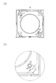
- FIG. It is drawing explaining 2nd Embodiment of the mobile telephone concerning this invention, Comprising: (a) is a top view of the base of a lens drive device, (b) is a partially expanded plane of the shaft vicinity of (a).
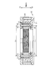
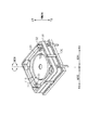
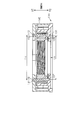
- FIG. It is drawing explaining 2nd Embodiment of the mobile telephone concerning this invention, Comprising: It is an optical axis direction sectional view of a lens drive device.
- It is drawing explaining the conventional lens drive device Comprising: It is a perspective view of the state which removed the cover.
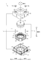
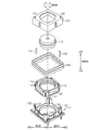
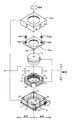
- 3rd Embodiment of the mobile telephone concerning this invention Comprising: It is a disassembled perspective view of the lens drive device of the camera module mounted in a mobile telephone.
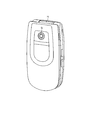
- FIG. 1 shows a folded state, and a cover glass 9 which is a part of the camera module is exposed on the front surface.
- FIG. 2A is a diagram in which the mobile phone is opened and the display unit 81 and the operation unit 82 are in front.
- FIG. 2B is a view of the opened mobile phone as viewed from the back. The photographer turns the shutter by operating the operation unit 82 while confirming the image on the display unit 81 toward the object for which the cover glass 9 is desired to be photographed with the mobile phone opened in this manner. You can shoot.
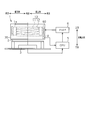
- a filter 2 and an image sensor 3 are disposed on the base 30 side of the lens driving device 1.
- the Hall element 4 is disposed as a position detection element. Based on the signal from the Hall element 4, the position of the lens module 1a is detected.
- a CPU Central Processing Unit
- the driver 6 controls the driver 6 to move the lens module 1a upward from the home position to a preset position in the optical axis direction.
- a position detection signal from the Hall element 4 is input to the CPU 5.
- the CPU 5 processes a signal input from the image sensor 3 to obtain a contrast value of the captured image. Such an operation is repeated, and the position of the lens module 1a having the best contrast value is acquired as the in-focus position.
- the CPU 5 drives the lens module 1a to such a focus position. Specifically, the CPU 5 monitors the signal from the hall element 4 and drives the lens module 1a until the signal from the hall element 4 is in a state corresponding to the in-focus position. With this operation, the lens module 1a moves to the in-focus position.
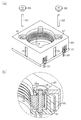
- the lens driving device 1 includes a lens module 1a that can move in the optical axis direction, and a fixed body 1b that applies driving force to the lens module 1a and is fixed to a device on which the lens driving device 1 is mounted. Yes.
- the lens driving device 1 moves the lens module 1a in the optical axis direction to realize autofocus.
- the lens driving device 1 of the present embodiment is formed in a square of about 8.5 mm in a plan view in the optical axis direction, and the height of the lens driving device 1 in the optical axis direction is formed to be about 3 mm. ing.
- the lens module 1a is also formed with a lens unit 13 including a plurality of optical lenses 11 and a lens barrel 12 that holds the plurality of optical lenses 11, and a resin that holds the lens unit 13, with reference to FIG. It is comprised by the holder 10 and the some magnet 20 fixed to the holder 10.
- FIG. Note that four magnets 20 of the present embodiment are fixed to the holder 10 so as to surround the lens unit 13 in the circumferential direction from the outside in the radial direction through a certain distance in the circumferential direction.
- the holder 10 is formed by injection molding a resin material. At that time, a magnet 20 is mounted on a mold for forming the holder 10 in advance, and the holder is integrally formed with the magnet 20 simultaneously with injection molding.
- the bonding strength between the magnet 20 and the holder 10 can be improved as compared with the case where the magnet 20 and the holder 10 are bonded with an adhesive. Moreover, the attachment process of the magnet 20 can be omitted, which contributes to cost reduction.
- the holder 10 has a main shaft hole 15 that is a through hole in the optical axis direction into which the main shaft 51 is inserted, and a sub shaft that is a through hole in the optical axis direction into which the sub shaft 52 is inserted.
- a shaft hole 16 is provided. Since the main shaft 51 and the sub shaft 52 are arranged in the optical axis direction of the lens unit 13, the inner peripheral surface of the main shaft hole 15 is brought into sliding contact with the outer peripheral surface of the main shaft 51, and The lens module 1a can be moved in the optical axis direction by moving the holder 10 in a state where the peripheral surface is in sliding contact with the outer peripheral surface of the sub shaft 52.
- the fixed body 1b is fixed to the base 30 and the cover 40 that constitute the outer frame of the lens driving device 1, and the above-described main shaft 51 and sub shaft 52 that guide the movement of the holder 10 in the optical axis direction. And a coil 60 that forms a magnetic field when an electric current is applied thereto.
- a magnetic plate 70 which is a rectangular plate-like magnetic member formed of a magnetic steel plate, is fixed to the base 30 outside the coil 60 in the radial direction.
- the base 30 is provided with a base portion 31 constituting the lower surface of the outer frame of the lens driving device 1 and a support column 32 extending from the base portion 31 along the optical axis direction.
- the base 31 is formed in a square shape in a plan view in the optical axis direction.
- the support columns 32 are provided at the four corners of the base 31.
- An opening 33 that is a circular through hole is formed at the center of the base 31.
- the base 30 supports a lower end portion (hereinafter simply referred to as “lower end portion”) of the main shaft 51 in the optical axis direction of which the central axis is directed in the optical axis direction of the lens unit 13.
- a shaft lower end support portion 37 is provided as a recess for the purpose.
- a shaft lower end support portion 38 which is a recess for supporting the lower end portion of the sub shaft 52 whose central axis is directed in the optical axis direction of the lens unit 13 is provided.
- the cover 40 constituting the outer side surface and the upper surface of the lens driving device 1 is attached to the base 30 so as to surround the outer side in the radial direction of the coil 60.
- the upper surface of the cover 40 is provided with a shaft upper end support hole 41 which is a through hole for supporting an upper end portion (hereinafter simply referred to as “upper end portion”) of the main shaft 51 in the optical axis direction.
- a shaft upper end support hole 42 which is a through hole for supporting the upper end portion of the sub shaft 52 is also provided.
- the cross section perpendicular to the optical axis direction of the shaft upper end support hole 41 and the shaft upper end support hole 42 is larger than the cross section perpendicular to the axial direction of the corresponding main shaft 51 and sub shaft 52, respectively. . Therefore, even if the center positions of the shaft upper end support hole 41 and the shaft upper end support hole 42 are deviated from the positions where the center positions of the shaft lower end support portion 37 and the shaft lower end support portion 38 are extended in the optical axis direction.
- the cross-sectional difference absorbs or reduces the misalignment, so that the shaft extending direction is restrained from being inclined with respect to the optical axis direction.
- a shaft fixing member 55 and a shaft fixing member 56 are further provided for fixing the upper ends of the main shaft 51 and the sub shaft 52 to the shaft upper end support hole 41 and the shaft upper end support hole 42, respectively.
- the upper end portion of the main shaft 51 is fixed to the shaft upper end support hole 41 via the shaft fixing member 55
- the upper end portion of the sub shaft 52 is fixed to the shaft upper end support hole 42 via the shaft fixing member 56.
- the shaft fixing member 55 and the shaft fixing member 56 seal the cylindrical portion into which the upper end portions of the main shaft 51 and the sub shaft 52 can be inserted, and the upper end portion of the cylindrical portion. It has a slewing disk-shaped part.
- the outer peripheral surface of the cylindrical portion of the shaft fixing member 56 is a concave groove for restricting the adhesive applied to the shaft fixing member 56 from moving downward.
- An adhesive movement restricting portion 56a is formed.
- the outer peripheral surface of the cylindrical portion of the shaft fixing member 55 is also a concave groove for restricting the adhesive applied to the shaft fixing member 55 from moving downward.
- An adhesive movement restricting portion is formed.
- a recessed portion that is recessed downward in a circular shape is provided in the periphery of the upper end support hole 41 and the shaft upper end support hole 42 on the upper surface of the cover 40. Since the depth of the recessed portion is substantially the same as the thickness of the disk-shaped portion of the shaft fixing member 56, the height of the lens driving device 1 is higher than that of the conventional device even after the shaft fixing member 56 is attached. It will never grow. Further, since the diameter of the recessed portion is larger than the diameter of the disk-shaped portion of the shaft fixing member 56, the fixing position of the fixing member 56 is not limited by the recessed portion.
- the main shaft 51 and the sub shaft 52 of the lens driving device 1 are arranged in the optical axis direction as follows, for example.
- the base 30 is fixed to a jig or the like (not shown), and the lens module 1a including the holder 10 and the cover 40 are assembled.
- the shaft lower end support portion 37, the main shaft hole 15 and the shaft upper end support hole 41 are arranged in the optical axis direction
- the shaft lower end support portion 38, the sub shaft hole 16 and the shaft upper end support hole 42 are arranged in the optical axis direction.
- the main shaft 51 is inserted from above in the optical axis direction in the order of the shaft upper end support hole 41, the main shaft hole 15, and the shaft lower end support portion 37.
- the lower end portion of the main shaft 51 is accurately supported in the optical axis direction. Since the cross section perpendicular to the optical axis direction of the shaft upper end support hole 41 is larger than the cross section perpendicular to the optical axis direction of the main shaft 51, if the main shaft 51 stands in the optical axis direction with the shaft lower end support portion 37 as a fulcrum, The direction of the support hole 41 is not inclined.
- the sub shaft 52 is inserted in the order of the shaft upper end support hole 42, the sub shaft hole 16 and the shaft lower end support portion 38, and the shaft lower end support portion 38 causes the lower end portion of the sub shaft 52 to be inserted. Is accurately supported in the optical axis direction. Since the cross section perpendicular to the optical axis direction of the shaft upper end support hole 42 is larger than the cross section perpendicular to the optical axis direction of the sub shaft 52, if the sub shaft 52 stands in the optical axis direction with the shaft lower end support portion 38 as a fulcrum, The direction of the support hole 42 is not inclined.
- the shaft fixing member 55 is attached to the upper end portion of the main shaft 51 by inserting the cylindrical portion of the shaft fixing member 55, and the shaft fixing member 55 is bonded to the shaft upper end support hole 41, thereby allowing the shaft fixing member 55 to pass through.
- the upper end portion of the main shaft 51 is supported by the shaft upper end support hole 41.
- the auxiliary shaft 52 is also supported at the upper end portion of the auxiliary shaft 52 by the shaft upper end support hole 42 via the shaft fixing member 56. In this way, both the main shaft 51 and the sub shaft 52 can be disposed in the optical axis direction.
- the lens driving device 1 of the present embodiment According to the lens driving device 1 of the present embodiment, the following effects can be obtained.
- the cross sections perpendicular to the optical axis direction of the two shaft upper end support holes 41 and 42 are larger than the cross sections perpendicular to the optical axis direction of the corresponding main shaft 51 and sub shaft 52, respectively. Therefore, even if the center positions of the shaft upper end support holes 41 and 42 are deviated from the positions where the center positions of the shaft lower end support portions 37 and 38 are extended in the optical axis direction, the difference in the cross section causes the position shift. By absorbing or reducing, it is suppressed that the extending direction of the main shaft 51 and the sub shaft 52 is supported with being inclined with respect to the optical axis direction.
- the two shaft upper end support holes 41 and 42 support the upper end portion of the shaft via the shaft fixing members 55 and 56. Therefore, as described above, even if the cross section perpendicular to the optical axis direction of the shaft upper end support holes 41 and 42 is larger than the cross section perpendicular to the optical axis direction of the corresponding main shaft 51 and sub shaft 52, respectively.
- the main shaft 51 and the sub shaft 52 can be reliably fixed to the shaft upper end support holes 41 and 42 by the shaft fixing members 55 and 56, respectively.
- the shaft fixing members 55 and 56 are provided with an adhesive movement restricting portion for restricting the adhesive applied to the shaft fixing members 55 and 56 from moving downward. Therefore, even when the shaft fixing members 55 and 56 are fixed to the shaft upper end support holes 41 and 42 respectively by the adhesive, the adhesive applied to the shaft fixing members 55 and 56 moves downward, and the lens driving device 1 is prevented from harming.
- the camera module of this embodiment is equipped with the lens driving device 1 described above. Since the lens driving device 1 described above is a lens driving device that facilitates the movement of the lens module, it is a lens driving device with high driving accuracy. Therefore, a camera module equipped with this lens driving device can be a highly accurate camera module.
- the mobile phone of this embodiment is equipped with the camera module described above. Since this camera module is a small and highly accurate camera module as described above, it is suitable as a camera module mounted on a mobile phone.
- the upper ends of the main shaft 51 and the sub shaft 52 are directly fixed to the shaft upper end support hole 41 and the shaft upper end support hole 42, respectively, and the shaft fixing member 55 is not used.
- a cross section perpendicular to the optical axis direction of at least one shaft lower end support portion among the plurality of shaft lower end support portions is larger than a cross section perpendicular to the optical axis direction of the corresponding shaft among the plurality of shafts.
- the shape of the cross section perpendicular to the optical axis direction of at least one shaft lower end support portion of the plurality of shaft lower end support portions is an oval
- the cross section perpendicular to the optical axis direction of the corresponding shaft is The shape is a circle having a smaller diameter than this oval.
- the shape of the cross section perpendicular to the optical axis direction of the shaft lower end support portion 38 corresponding to the sub shaft 52 is an oval.
- the minor axis of the ellipse is substantially equal to the diameter of the secondary shaft 52, and the major axis of the ellipse is larger than the diameter of the secondary shaft 52. Therefore, the cross section perpendicular to the optical axis direction of the shaft lower end support portion 38 is larger than the cross section perpendicular to the optical axis direction of the auxiliary shaft 52.
- the major axis of the oval is the same direction as the straight line connecting the shaft lower end support portion 37 and the shaft lower end support portion 38 facing each other. In the present embodiment, specifically, it is the radial direction. Therefore, for example, even when the auxiliary shaft 52 corresponding to the shaft lower end support portion 38 is inclined with respect to the optical axis direction, the inclination direction is the direction of the main shaft 51. Therefore, even when the sub shaft 52 is inclined in the radial direction, if the main shaft 51 is accurately fixed in the optical axis direction, the influence is suppressed by the main shaft 51, and the lens module 1a may be inclined. It is suppressed.
- the lens module 1a can be tilted.
- the main shaft 51 and the sub shaft 52 of the lens driving device 1 are arranged in the optical axis direction as follows, for example.
- the base 30 is fixed to a jig or the like (not shown), and the lens module 1a including the holder 10 and the cover 40 are assembled.
- the shaft lower end support portion 37, the main shaft hole 15 and the shaft upper end support hole 41 are arranged in the optical axis direction
- the shaft lower end support portion 38, the sub shaft hole 16 and the shaft upper end support hole 42 are arranged in the optical axis direction.
- the main shaft 51 is inserted from above in the optical axis direction in the order of the shaft upper end support hole 41, the main shaft hole 15, and the shaft lower end support portion 37.
- the lower end portion of the main shaft 51 is accurately supported in the optical axis direction.
- the cross section perpendicular to the optical axis direction of the shaft upper end support hole 41 is substantially equal to the cross section perpendicular to the optical axis direction of the main shaft 51, the upper end portion of the main shaft 51 is directly fixed by the shaft upper end support hole 41, Supported.
- the center of the shaft upper end support hole 41 and the center of the shaft lower end support portion 37 are light-transmitted. By matching in the axial direction, the main shaft can be accurately supported in the optical axis direction.
- the sub shaft 52 can also be disposed in the optical axis direction by inserting the sub shaft 52 in the same manner as the main shaft 51 in the optical axis direction with the center position of the shaft upper end support hole 42 as a reference.
- the cross section perpendicular to the optical axis direction of the shaft upper end support hole 42 is substantially equal to the cross section perpendicular to the optical axis direction of the sub shaft 52, the upper end portion of the sub shaft 52 is directly fixed by the shaft upper end support hole 42, Supported.
- the cross section perpendicular to the optical axis direction of the shaft lower end support portion 38 is larger than the cross section perpendicular to the optical axis direction of the sub shaft 52, the center of the shaft upper end support hole 42 and the center of the shaft lower end support portion 38 are formed. Even if it is not possible to match in the optical axis direction, the sub shaft can be accurately supported in the optical axis direction if the difference in the center can be absorbed by the difference in cross section.
- the distance Lb between the centers of the shaft lower end support portion 37 and the shaft lower end support portion 38 does not match the distance Lc between the centers of the shaft upper end support hole 41 and the shaft upper end support hole 42. Even so, if the difference in distance can be absorbed by the difference between the cross section of the shaft lower end support portion 38 and the cross section of the sub shaft 52, both the main shaft 51 and the sub shaft 52 are supported in the optical axis direction.
- the cross section perpendicular to the optical axis direction of one shaft lower end support portion 38 of the two shaft lower end support portions 37 and 38 is perpendicular to the optical axis direction of the corresponding sub shaft 52. Larger than cross section. Therefore, even when the center position of the shaft upper end support hole is deviated from the position where the center position of the shaft lower end support portion is extended in the optical axis direction, the difference in the cross section absorbs or reduces the position shift. Thus, the shaft extending direction is restrained from being inclined with respect to the optical axis direction.
- the cross section perpendicular to the optical axis direction of the shaft lower end support portion 38 is larger than the cross section perpendicular to the optical axis direction of the corresponding sub shaft 52. Therefore, even when the center position of the shaft upper end support hole 42 is deviated from the position where the center position of the shaft lower end support portion 38 is extended in the optical axis direction, the difference in the cross section absorbs the position shift. Thus, the extending direction of the sub shaft 52 is suppressed from being inclined with respect to the optical axis direction.
- the shape of the cross section perpendicular to the optical axis direction of the shaft lower end support portion 38 is oval, and the shape of the cross section of the corresponding sub shaft 52 perpendicular to the optical axis direction is It is a circle with a smaller diameter than the circle. Therefore, even if the center position of the shaft upper end support hole 42 is shifted in the major axis direction of the oval from the position where the center position of the shaft lower end support portion 38 is extended in the optical axis direction, the extension of the shaft is extended. It is suppressed that the direction is inclined and supported with respect to the optical axis direction.
- the camera module of the second embodiment is equipped with the lens driving device 1 described above. Since the lens driving device 1 described above is a lens driving device that facilitates the movement of the lens module, it is a lens driving device with high driving accuracy. Therefore, a camera module equipped with this lens driving device can be a highly accurate camera module.
- the mobile phone of the second embodiment is equipped with the camera module described above. Since this camera module is a small and highly accurate camera module as described above, it is suitable as a camera module mounted on a mobile phone.
- the shaft upper end support hole 41 and the shaft upper end support hole 42 of the cover 40 of the first embodiment are eliminated, and the shaft upper end support hole 410 and the shaft upper end support hole are introduced into the newly introduced shaft holder 500.
- a contact portion 430 is provided for positioning to the base 30.
- the shaft upper end support hole 410 and the shaft upper end support hole 420 By introducing the shaft upper end support hole 410 and the shaft upper end support hole 420 into the shaft holder 500, the same effects as those of the first embodiment are obtained. Furthermore, in order to form the shaft upper end support holes 410, 420 in a flat shape like the shaft holder 500, the shaft upper end support hole 41, in a complicated shape like the cover 40 of the first embodiment. 42 does not need to be formed and can be manufactured easily.
- the third embodiment can also be applied to the second embodiment.
- the cross section perpendicular to the optical axis direction of the shaft upper end support hole 41 and the shaft upper end support hole 42 is larger than the cross section perpendicular to the axial direction of the corresponding main shaft 51 and sub shaft 52, respectively.
- Other configurations may be used.
- the cross section perpendicular to the optical axis direction of the shaft upper end support hole 42 is larger than the cross section perpendicular to the axial direction of the sub shaft 52, but the shaft upper end support hole 41 has the same area as the cross section perpendicular to the axial direction of the main shaft 51. There may be.
- the extension direction of the main shaft 51 and the sub shaft 52 is inclined with respect to the optical axis direction due to the difference in cross section between the shaft upper end support hole 42 and the sub shaft 52 absorbing the displacement. It can suppress that it is supported.
- the third embodiment also has the same effect.
- the two shaft upper end support holes 41 and 42 are supported at the upper end portion of the shaft via the shaft fixing members 55 and 56, but may have other configurations.
- the shaft fixing members 55 and 56 may be fixed without using one. If the shaft upper end support hole 41 has the same area as the cross section perpendicular to the axial direction of the main shaft 51 as in the above modification, the upper end portion of the main shaft 51 is connected to the shaft upper end support hole 41 without using the shaft fixing member 55. Directly supported by In this case, the number of parts and the mounting process of the shaft fixing member 55 can be omitted, which contributes to cost reduction.
- the third embodiment can have the same configuration and the same operation and effect.
- the shaft fixing member 56 can be omitted. In this case, since the number of parts and the mounting process of the shaft fixing member 56 can be omitted, the cost can be further reduced.
- an adhesive movement restricting portion for restricting the adhesive applied to the shaft fixing members 55 and 56 from moving downward is provided on the outer peripheral surface of the cylindrical portion of the shaft fixing member 56.
- the adhesive applied to the shaft fixing members 55 and 56 can be restricted from moving downward, so that the convex portion provided on the outer peripheral surface of the cylindrical portion, the step portion, or the rough surface processed portion can be used. There may be. Further, if it is not a problem that the adhesive moves downward, the adhesive movement restriction part itself may be omitted. At this time, it can be applied to the shaft fixing members 550 and 560 of the third embodiment, and the same operation and effect are obtained.
- vertical to the optical axis direction of the shaft lower end support part 38 is an oval, and the shape of the cross section perpendicular
- the difference between the cross section perpendicular to the optical axis direction of the shaft lower end support portion 38 and the cross section perpendicular to the optical axis direction of the sub shaft 52 absorbs the positional deviation, so that the extending direction of the shaft becomes the optical axis direction. Since it is only necessary to be supported by being inclined, the cross-sectional shape is not limited as long as the shapes correspond to each other.
- the cross section perpendicular to the optical axis direction of the shaft lower end support portion 38 is larger than the cross section perpendicular to the optical axis direction of the corresponding sub shaft 52, but other configurations may be used.
- the cross section perpendicular to the optical axis direction of the shaft lower end support portion 37 is also perpendicular to the optical axis direction of the corresponding main shaft 51. It may be larger than the cross section. In this case, the main shaft 51 can be supported in the optical axis direction even when the center of the shaft upper end support hole 41 and the center of the shaft lower end support portion 37 are displaced in the optical axis direction.
- only one sub shaft 52 is used, but a plurality of sub shafts 52 may be used.
- Increasing the number of sub-shafts can suppress the inclination of the lens module 1a with respect to the optical axis direction.
- the cross section perpendicular to the optical axis direction of the corresponding shaft upper end support hole is made larger than the cross section perpendicular to the optical axis direction of the auxiliary shaft, or the optical axis of the corresponding shaft lower end support portion.
- the main shaft 51 and the sub shaft 52 are moved in the optical axis direction even when the positions of the center of the shaft upper end support hole and the center of the shaft lower end support portion are shifted in the optical axis direction. It becomes possible to support.
- the lens driving device is mounted on the camera module, but may have other configurations.
- an autofocus function can be added to such an optical device.
- the camera module is mounted on the mobile phone, but other configurations may be used. It may be a compact digital camera, a digital single-lens reflex camera, or a camera for silver salt photography. Further, it may be mounted on a digital video camera or a film camera for moving image shooting.
- SYMBOLS 1 ... Lens drive device, 1a ... Lens module, 1b ... Fixed body, 2 ... Filter, 3 ... Image sensor, 4 ... Hall element, 6 ... Driver, 9 ... Cover glass, 10 ... Holder, 11 ... Optical lens, 12 ... Lens barrel, 13 ... lens unit, 15 ... main shaft hole, 16 ... sub shaft hole, 20 ... magnet, 30 ... base, 31 ... base, 32 ... column, 33 ... opening, 37 ... shaft lower end support, 38 ... Shaft lower end support, 40 ... cover, 400 ... cover, 41 ... shaft upper end support hole, 42 ... shaft upper end support hole, 410 ... shaft upper end support hole, 420 ...
- shaft upper end support hole, 430 ... contact portion, 500 ... shaft Holder 51 ... Main shaft 52 ... Sub shaft 55,56 ... Shaft fixing member 550,560 ... Shaft fixing member 56a ... Adhesive movement restriction , 60 ... Coil, 70 ... Magnetic plate, 81 ... Display unit, 82 ... Operation unit, 110 ... Holder, 113 ... Lens unit, 115 ... Shaft hole, 116 ... Shaft hole, 120 ... Magnet, 130 ... Base, 131 ... Base DESCRIPTION OF SYMBOLS 137 ... Shaft lower end support part, 138 ... Shaft lower end support part, 140 ... Cover, 141 ... Shaft upper end support hole, 142 ... Shaft upper end support hole, 151 ... Shaft, 152 ... Shaft, 160 ... Coil, H ... Hinge
Landscapes
- Engineering & Computer Science (AREA)
- Multimedia (AREA)
- Signal Processing (AREA)
- Physics & Mathematics (AREA)
- General Physics & Mathematics (AREA)
- Optics & Photonics (AREA)
- Lens Barrels (AREA)
- Studio Devices (AREA)
Abstract
Description
以下、本発明の携帯電話を具体化した携帯電話の一実施形態を図面を用いて説明する。
図1に示すように、係る携帯電話はヒンジHを中心に折り畳む構成の携帯電話である。図1は折り畳んだ状態を示す図であり前面にはカメラモジュールの一部であるカバーガラス9が露出している。図2(a)は、この携帯電話を開いて表示部81、操作部82を前面にした図である。図2(b)は、開いた携帯電話を背面から見た図である。撮影者は、このように携帯電話を開いた状態でカバーガラス9を撮影したい対象に向けて、表示部81で画像を確認しつつ、操作部82を操作することによりシャッターを切り、対象物を撮影することができる。
次に、本発明を具体化した携帯電話の第2の実施形態を図7にしたがって説明する。なお、第2の実施形態は、第1の実施形態のカバー40およびベース30の構造を変更したのみの構成であるため、同様の部分についてはその詳細な説明を省略する。
従って、シャフト下端支持部38の光軸方向に垂直な断面が、副シャフト52の光軸方向に垂直な断面より大きい。
次に、本発明を具体化した携帯電話の第3の実施形態を図12にしたがって説明する。なお、第3の実施形態はシャフトホルダー500を導入し、第1の実施形態のカバー40およびベース30の構造を変更したのみの構成であるため、同様の部分についてはその詳細な説明を省略する。
着剤が下方に移動することが問題とならないのであれば、接着剤移動規制部自体を割愛し
ても良い。この時、第3の実施形のシャフト固定部材550および560にも応用出来同様な作用効果となる。
長円形であり、対応する副シャフト52の光軸方向に垂直な断面の形状が、この長円形よ
り小径の円形であるが他の構成であっても良い。要はシャフト下端支持部38の光軸方向
に垂直な断面と副シャフト52の光軸方向に垂直な断面との差が位置のずれを吸収するこ
とにより、シャフトの延設方向が光軸方向に対して傾いて支持されることが抑制されれば
よいのであるから、互いに対応する形状であれば、断面形状は限定されない。
Claims (9)
- レンズユニットを保持するホルダと、
前記ホルダの光軸方向の移動をガイドするとともに、前記レンズユニットの光軸方向に中心軸が向けられる、柱状の複数のシャフトと、
機器に固定される基部と、
前記複数のシャフトの下端部を支持するとともに前記基部に設けられた複数のシャフト下端支持部と、
前記レンズユニット、前記ホルダ、前記複数のシャフトおよび前記基部を覆うことにより保護するカバーと、
前記複数のシャフトの上端部を挿入させることができる貫通孔であるとともに、前記複数のシャフトの上端部を支持する前記カバーに設けられた複数のシャフト上端支持孔とを備えたレンズ駆動装置において、
前記複数のシャフト上端支持孔のうち少なくとも1つのシャフト上端支持孔の光軸方向に垂直な断面が、前記複数のシャフトのうち対応するシャフトの光軸方向に垂直な断面より大きいことを特徴とするレンズ駆動装置。 - レンズユニットを保持するホルダと、
前記ホルダの光軸方向の移動をガイドするとともに、前記レンズユニットの光軸方向に中心軸が向けられる、柱状の複数のシャフトと、
機器に固定される基部と、
前記複数のシャフトの下端部を支持するとともに前記基部に設けられた複数のシャフト下端支持部と、
前記複数のシャフトの上端部を挿入させることができる貫通孔であるとともに、前記複数のシャフトの上端部を支持する複数のシャフト上端支持孔を有するシャフトホルダーと、
前記レンズユニット、前記ホルダ、前記複数のシャフト、前記シャフトホルダーおよび前記基部を覆うことにより保護するカバーとを備えたレンズ駆動装置において、
前記複数のシャフト上端支持孔のうち少なくとも1つのシャフト上端支持孔の光軸方向に垂直な断面が、前記複数のシャフトのうち対応するシャフトの光軸方向に垂直な断面より大きいことを特徴とするレンズ駆動装置。 - 前記シャフトを前記シャフト上端支持孔に固定するシャフト固定部材を更に備え、
前記シャフト上端支持孔のうち少なくとも1つのシャフト上部支持部は前記シャフト固定部材を介して前記シャフトの前記上端部を支持することを特徴とする請求項1又は2に記載のレンズ駆動装置。 - 前記シャフト固定部材に塗布された接着剤が下方に移動することを規制するための接着剤移動規制部が、前記シャフト固定部材に設けられていることを特徴とする請求項3に記載のレンズ駆動装置。
- レンズユニットを保持するホルダと、
前記ホルダの光軸方向の移動をガイドするとともに、前記レンズユニットの光軸方向に中心軸が向けられる、柱状の複数のシャフトと、
機器に固定される基部と、
前記複数のシャフトの下端部を支持するとともに前記基部に設けられた複数のシャフト下端支持部と、
前記レンズユニット、前記ホルダ、前記複数のシャフトおよび前記基部を覆うことにより保護するカバーと、
前記複数のシャフトの上端部を挿入させることができる貫通孔であるとともに、前記複数のシャフトの上端部を支持する前記カバーに設けられた複数のシャフト上端支持孔とを備えたレンズ駆動装置において、
前記複数の下端支持部が前記シャフトの下端部を挿入することができる凹陥であり、
前記複数のシャフト下端支持部のうち少なくとも1つのシャフト下端支持部の光軸方向に垂直な断面が、前記複数のシャフトのうち対応するシャフトの光軸方向に垂直な断面より大きいことを特徴とするレンズ駆動装置。 - レンズユニットを保持するホルダと、
前記ホルダの光軸方向の移動をガイドするとともに、前記レンズユニットの光軸方向に中心軸が向けられる、柱状の複数のシャフトと、
機器に固定される基部と、
前記複数のシャフトの下端部を支持するとともに前記基部に設けられた複数のシャフト下端支持部と、
前記複数のシャフトの上端部を挿入させることができる貫通孔であるとともに、前記複数のシャフトの上端部を支持する複数のシャフト上端支持孔を有するシャフトホルダーと、
前記レンズユニット、前記ホルダ、前記複数のシャフト、前記シャフトホルダーおよび前記基部を覆うことにより保護するカバーとを備えたレンズ駆動装置において、
前記複数の下端支持部が前記シャフトの下端部を挿入することができる凹陥であり、
前記複数のシャフト下端支持部のうち少なくとも1つのシャフト下端支持部の光軸方向に垂直な断面が、前記複数のシャフトのうち対応するシャフトの光軸方向に垂直な断面より大きいことを特徴とするレンズ駆動装置。 - 前記複数のシャフト下端支持部のうち少なくとも1つのシャフト下端支持部の光軸方向に垂直な断面の形状が、複数のシャフト下端支持部のうち対向する2つのシャフト下端支持部を結ぶ方向を長径とする長円形であり、
前記対応するシャフトの光軸方向に垂直な断面の形状が、前記長円形より小径の円形であることを特徴とする請求項5又は6に記載のレンズ駆動装置。 - 請求項1~請求項7のいずれか一項に記載のレンズ駆動装置が搭載されていることを特徴とするカメラモジュール。
- 請求項8に記載のカメラモジュールが搭載されていることを特徴とする携帯電話。
Priority Applications (2)
| Application Number | Priority Date | Filing Date | Title |
|---|---|---|---|
| US13/392,973 US20120154671A1 (en) | 2009-09-03 | 2010-09-01 | Lens drive device, and camera module and cellular phone equipped with lens drive device |
| JP2011529906A JPWO2011027761A1 (ja) | 2009-09-03 | 2010-09-01 | レンズ駆動装置およびレンズ駆動装置を搭載したカメラモジュール、携帯電話 |
Applications Claiming Priority (2)
| Application Number | Priority Date | Filing Date | Title |
|---|---|---|---|
| JP2009203794 | 2009-09-03 | ||
| JP2009-203794 | 2009-09-03 |
Publications (1)
| Publication Number | Publication Date |
|---|---|
| WO2011027761A1 true WO2011027761A1 (ja) | 2011-03-10 |
Family
ID=43649296
Family Applications (1)
| Application Number | Title | Priority Date | Filing Date |
|---|---|---|---|
| PCT/JP2010/064879 Ceased WO2011027761A1 (ja) | 2009-09-03 | 2010-09-01 | レンズ駆動装置およびレンズ駆動装置を搭載したカメラモジュール、携帯電話 |
Country Status (3)
| Country | Link |
|---|---|
| US (1) | US20120154671A1 (ja) |
| JP (1) | JPWO2011027761A1 (ja) |
| WO (1) | WO2011027761A1 (ja) |
Families Citing this family (1)
| Publication number | Priority date | Publication date | Assignee | Title |
|---|---|---|---|---|
| KR101170084B1 (ko) * | 2010-12-24 | 2012-07-31 | 엘지이노텍 주식회사 | 카메라 모듈 |
Citations (6)
| Publication number | Priority date | Publication date | Assignee | Title |
|---|---|---|---|---|
| JP2005055761A (ja) * | 2003-08-06 | 2005-03-03 | Sony Corp | 撮像装置およびレンズ装置並びに撮像装置およびレンズ装置の製造方法 |
| JP2006304225A (ja) * | 2005-04-25 | 2006-11-02 | Matsushita Electric Works Ltd | カメラ付きドアホン子機 |
| JP2006301058A (ja) * | 2005-04-18 | 2006-11-02 | Seiko Instruments Inc | レンズ駆動装置及びカメラモジュール |
| JP2008026784A (ja) * | 2006-07-25 | 2008-02-07 | Seiko Instruments Inc | レンズ駆動モジュール及びカメラモジュール並びに電子機器 |
| JP2009069611A (ja) * | 2007-09-14 | 2009-04-02 | Sanyo Electric Co Ltd | レンズ駆動装置 |
| JP2009150950A (ja) * | 2007-12-19 | 2009-07-09 | Sony Corp | レンズ鏡筒および撮像装置 |
-
2010
- 2010-09-01 JP JP2011529906A patent/JPWO2011027761A1/ja active Pending
- 2010-09-01 WO PCT/JP2010/064879 patent/WO2011027761A1/ja not_active Ceased
- 2010-09-01 US US13/392,973 patent/US20120154671A1/en not_active Abandoned
Patent Citations (6)
| Publication number | Priority date | Publication date | Assignee | Title |
|---|---|---|---|---|
| JP2005055761A (ja) * | 2003-08-06 | 2005-03-03 | Sony Corp | 撮像装置およびレンズ装置並びに撮像装置およびレンズ装置の製造方法 |
| JP2006301058A (ja) * | 2005-04-18 | 2006-11-02 | Seiko Instruments Inc | レンズ駆動装置及びカメラモジュール |
| JP2006304225A (ja) * | 2005-04-25 | 2006-11-02 | Matsushita Electric Works Ltd | カメラ付きドアホン子機 |
| JP2008026784A (ja) * | 2006-07-25 | 2008-02-07 | Seiko Instruments Inc | レンズ駆動モジュール及びカメラモジュール並びに電子機器 |
| JP2009069611A (ja) * | 2007-09-14 | 2009-04-02 | Sanyo Electric Co Ltd | レンズ駆動装置 |
| JP2009150950A (ja) * | 2007-12-19 | 2009-07-09 | Sony Corp | レンズ鏡筒および撮像装置 |
Also Published As
| Publication number | Publication date |
|---|---|
| US20120154671A1 (en) | 2012-06-21 |
| JPWO2011027761A1 (ja) | 2013-02-04 |
Similar Documents
| Publication | Publication Date | Title |
|---|---|---|
| KR100935312B1 (ko) | 초소형 카메라 모듈용 손떨림 보정장치 | |
| US10348968B2 (en) | Method for producing camera module | |
| KR101073442B1 (ko) | 판 스프링, 렌즈 구동장치 및 판 스프링의 제조방법 | |
| US12560853B2 (en) | Optical element driving mechanism | |
| CN103348275B (zh) | 相机模块的制造方法、相机模块、以及电子设备 | |
| KR101012720B1 (ko) | 카메라 모듈 | |
| US8503121B2 (en) | Lens driving device capable of suppressing a reduction of magnetic efficiency of a magnetic circuit | |
| JP5825534B2 (ja) | カメラモジュール | |
| US20190049690A1 (en) | Lens driving device | |
| KR20160121298A (ko) | 렌즈 구동 장치 및 이를 포함하는 카메라 모듈 | |
| WO2011068115A1 (ja) | レンズ駆動装置およびレンズ駆動装置を搭載したカメラモジュール、携帯電話 | |
| WO2011027685A1 (ja) | レンズ駆動装置及びこのレンズ駆動装置を搭載したカメラモジュール、携帯電話 | |
| KR20170120112A (ko) | 렌즈 구동장치, 카메라 모듈, 및 카메라 탑재 장치 | |
| JP6207955B2 (ja) | カメラモジュール、およびカメラモジュールの製造方法 | |
| KR100987934B1 (ko) | 렌즈 구동장치 | |
| CN219268983U (zh) | 用于光学图像防抖的致动器及包括致动器的相机模块 | |
| US12498534B2 (en) | Optical system | |
| JP2010160435A (ja) | レンズ駆動装置及びこのレンズ駆動装置を搭載したカメラモジュール | |
| JP2007155801A (ja) | カメラモジュール | |
| KR101068124B1 (ko) | 카메라 모듈용 보이스 코일 모터 | |
| JP2011112933A (ja) | レンズ駆動装置およびレンズ駆動装置を搭載したカメラモジュール、携帯電話 | |
| JPWO2011027761A1 (ja) | レンズ駆動装置およびレンズ駆動装置を搭載したカメラモジュール、携帯電話 | |
| JP2010066292A (ja) | レンズユニット、撮像装置、光学機器、レンズユニットの組立方法および撮像装置の組立方法 | |
| JP4918385B2 (ja) | 八角形マイクロレンズのピント合わせ構造 | |
| WO2010058637A1 (ja) | レンズ駆動装置及びレンズ駆動装置を搭載したカメラモジュール |
Legal Events
| Date | Code | Title | Description |
|---|---|---|---|
| 121 | Ep: the epo has been informed by wipo that ep was designated in this application |
Ref document number: 10813710 Country of ref document: EP Kind code of ref document: A1 |
|
| WWE | Wipo information: entry into national phase |
Ref document number: 2011529906 Country of ref document: JP |
|
| WWE | Wipo information: entry into national phase |
Ref document number: 13392973 Country of ref document: US |
|
| NENP | Non-entry into the national phase |
Ref country code: DE |
|
| 122 | Ep: pct application non-entry in european phase |
Ref document number: 10813710 Country of ref document: EP Kind code of ref document: A1 |