WO2011027708A1 - Vehicle lamp fitting - Google Patents

Vehicle lamp fitting Download PDF

Info

Publication number
WO2011027708A1
WO2011027708A1 PCT/JP2010/064487 JP2010064487W WO2011027708A1 WO 2011027708 A1 WO2011027708 A1 WO 2011027708A1 JP 2010064487 W JP2010064487 W JP 2010064487W WO 2011027708 A1 WO2011027708 A1 WO 2011027708A1
Authority
WO
WIPO (PCT)
Prior art keywords
light
lens body
incident
dark boundary
emitted
Prior art date
Application number
PCT/JP2010/064487
Other languages
French (fr)
Japanese (ja)
Inventor
雅典 大野
Original Assignee
スタンレー電気株式会社
Priority date (The priority date is an assumption and is not a legal conclusion. Google has not performed a legal analysis and makes no representation as to the accuracy of the date listed.)
Filing date
Publication date
Application filed by スタンレー電気株式会社 filed Critical スタンレー電気株式会社
Priority to KR1020127005793A priority Critical patent/KR101772238B1/en
Priority to EP10813657.3A priority patent/EP2474779B1/en
Priority to CN201080039228.1A priority patent/CN102483209B/en
Publication of WO2011027708A1 publication Critical patent/WO2011027708A1/en
Priority to US13/412,579 priority patent/US8702287B2/en

Links

Images

Classifications

    • FMECHANICAL ENGINEERING; LIGHTING; HEATING; WEAPONS; BLASTING
    • F21LIGHTING
    • F21SNON-PORTABLE LIGHTING DEVICES; SYSTEMS THEREOF; VEHICLE LIGHTING DEVICES SPECIALLY ADAPTED FOR VEHICLE EXTERIORS
    • F21S41/00Illuminating devices specially adapted for vehicle exteriors, e.g. headlamps
    • F21S41/30Illuminating devices specially adapted for vehicle exteriors, e.g. headlamps characterised by reflectors
    • F21S41/32Optical layout thereof
    • F21S41/322Optical layout thereof the reflector using total internal reflection
    • FMECHANICAL ENGINEERING; LIGHTING; HEATING; WEAPONS; BLASTING
    • F21LIGHTING
    • F21SNON-PORTABLE LIGHTING DEVICES; SYSTEMS THEREOF; VEHICLE LIGHTING DEVICES SPECIALLY ADAPTED FOR VEHICLE EXTERIORS
    • F21S41/00Illuminating devices specially adapted for vehicle exteriors, e.g. headlamps
    • F21S41/10Illuminating devices specially adapted for vehicle exteriors, e.g. headlamps characterised by the light source
    • F21S41/14Illuminating devices specially adapted for vehicle exteriors, e.g. headlamps characterised by the light source characterised by the type of light source
    • F21S41/141Light emitting diodes [LED]
    • F21S41/143Light emitting diodes [LED] the main emission direction of the LED being parallel to the optical axis of the illuminating device
    • FMECHANICAL ENGINEERING; LIGHTING; HEATING; WEAPONS; BLASTING
    • F21LIGHTING
    • F21SNON-PORTABLE LIGHTING DEVICES; SYSTEMS THEREOF; VEHICLE LIGHTING DEVICES SPECIALLY ADAPTED FOR VEHICLE EXTERIORS
    • F21S41/00Illuminating devices specially adapted for vehicle exteriors, e.g. headlamps
    • F21S41/10Illuminating devices specially adapted for vehicle exteriors, e.g. headlamps characterised by the light source
    • F21S41/14Illuminating devices specially adapted for vehicle exteriors, e.g. headlamps characterised by the light source characterised by the type of light source
    • F21S41/141Light emitting diodes [LED]
    • F21S41/147Light emitting diodes [LED] the main emission direction of the LED being angled to the optical axis of the illuminating device
    • F21S41/148Light emitting diodes [LED] the main emission direction of the LED being angled to the optical axis of the illuminating device the main emission direction of the LED being perpendicular to the optical axis
    • FMECHANICAL ENGINEERING; LIGHTING; HEATING; WEAPONS; BLASTING
    • F21LIGHTING
    • F21SNON-PORTABLE LIGHTING DEVICES; SYSTEMS THEREOF; VEHICLE LIGHTING DEVICES SPECIALLY ADAPTED FOR VEHICLE EXTERIORS
    • F21S41/00Illuminating devices specially adapted for vehicle exteriors, e.g. headlamps
    • F21S41/10Illuminating devices specially adapted for vehicle exteriors, e.g. headlamps characterised by the light source
    • F21S41/14Illuminating devices specially adapted for vehicle exteriors, e.g. headlamps characterised by the light source characterised by the type of light source
    • F21S41/141Light emitting diodes [LED]
    • F21S41/155Surface emitters, e.g. organic light emitting diodes [OLED]
    • FMECHANICAL ENGINEERING; LIGHTING; HEATING; WEAPONS; BLASTING
    • F21LIGHTING
    • F21VFUNCTIONAL FEATURES OR DETAILS OF LIGHTING DEVICES OR SYSTEMS THEREOF; STRUCTURAL COMBINATIONS OF LIGHTING DEVICES WITH OTHER ARTICLES, NOT OTHERWISE PROVIDED FOR
    • F21V5/00Refractors for light sources
    • F21V5/04Refractors for light sources of lens shape
    • FMECHANICAL ENGINEERING; LIGHTING; HEATING; WEAPONS; BLASTING
    • F21LIGHTING
    • F21VFUNCTIONAL FEATURES OR DETAILS OF LIGHTING DEVICES OR SYSTEMS THEREOF; STRUCTURAL COMBINATIONS OF LIGHTING DEVICES WITH OTHER ARTICLES, NOT OTHERWISE PROVIDED FOR
    • F21V7/00Reflectors for light sources
    • F21V7/0091Reflectors for light sources using total internal reflection
    • FMECHANICAL ENGINEERING; LIGHTING; HEATING; WEAPONS; BLASTING
    • F21LIGHTING
    • F21YINDEXING SCHEME ASSOCIATED WITH SUBCLASSES F21K, F21L, F21S and F21V, RELATING TO THE FORM OR THE KIND OF THE LIGHT SOURCES OR OF THE COLOUR OF THE LIGHT EMITTED
    • F21Y2101/00Point-like light sources
    • FMECHANICAL ENGINEERING; LIGHTING; HEATING; WEAPONS; BLASTING
    • F21LIGHTING
    • F21YINDEXING SCHEME ASSOCIATED WITH SUBCLASSES F21K, F21L, F21S and F21V, RELATING TO THE FORM OR THE KIND OF THE LIGHT SOURCES OR OF THE COLOUR OF THE LIGHT EMITTED
    • F21Y2115/00Light-generating elements of semiconductor light sources
    • F21Y2115/10Light-emitting diodes [LED]

Definitions

  • the present invention relates to a vehicular lamp, and in particular, uses a light emitting diode (LED: Light Emitting Diode) as a light source, and uses a light guide (a lens body having a reflection surface that internally reflects light from the LED light source).
  • LED Light Emitting Diode
  • the present invention relates to a vehicular lamp that irradiates illumination light that forms a light distribution pattern for passing light (low beam).
  • Patent Document 1 discloses a vehicular lamp that uses a light emitting diode (LED) as a light source and controls light distribution of the LED light using a light guide.
  • FIG. 7 is a vertical sectional view showing the configuration of the vehicular lamp.
  • the light emitting element 100 a of the light source 100 is disposed upward of the vehicle, and the light guide 102 is disposed above the light source 100.
  • the light guide 102 includes an incident surface 104 on the vehicle lower side where light from the light source 100 enters the inside of the light guide 102, and a reflection surface 106 on the rear side of the vehicle where light incident on the inside from the incident surface 104 is reflected forward of the vehicle.
  • the light reflected by the reflecting surface is emitted from the light guide 102 to the outside of the light guide 102, and the light emitting surface 108 on the vehicle front side.
  • chromatic aberration chromatic aberration
  • chromatic aberration chromatic aberration
  • a blue or red strip-shaped illumination area appears above the light / dark boundary, and color separation is observed.
  • the color separation appears at the light / dark boundary of the light distribution pattern by the light guide, and hinders the uniformity of the light distribution pattern. For this reason, there is a fear that the legal requirement as a headlamp cannot be satisfied.
  • the problem of such unintended illumination areas is not limited to the case where the light guide is molded from a polycarbonate material, but is the case where the light guide is molded from another transparent material (glass, acrylic, etc.). However, it also occurs in a similar manner.
  • the present invention has been made in view of such circumstances, and in the case of irradiating light in the direction of the light / dark boundary of a light distribution pattern by an optical system using a light guide (a lens body having a reflection surface for internal reflection).
  • An object of the present invention is to provide a vehicular lamp that reduces the problem that an unintended illumination region is generated due to color dispersion above a light / dark boundary.
  • the vehicular lamp according to the first aspect of the present invention irradiates light used for forming a partial light distribution pattern constituting a predetermined white low beam light distribution pattern.
  • a lens body including a reflecting surface, and the reflecting surface is radiated from an end of the light source corresponding to the bright / dark boundary line and is incident perpendicularly to the incident surface without being refracted.
  • the first reflection region configured to internally reflect the reflected light, and the reflected light is emitted from the emission surface to form the light / dark boundary line, and emitted from an end of the light source corresponding to the light / dark boundary line
  • a second reflection region configured to distribute light below the light-dark boundary line, and is emitted from an end of the light source corresponding to the light-dark boundary line and is incident at an angle other than perpendicular to the incident surface.
  • the light having a wavelength shorter than the reference wavelength that is refracted according to the incident angle and is incident on the inside of the lens body is internally reflected so that the reflected light is emitted from the emission surface and is distributed below the light / dark boundary line.
  • a third reflective region configured to There.
  • a vehicular lamp according to a second aspect of the present invention is a lens body having a light source that emits visible light having a plurality of wavelength components, an incident surface, a reflective surface, and an output surface, and passes through the incident surface.
  • the shape of the surface and the exit surface is such that the light of the green wavelength included in the light in the visible light region emitted from the end of the light source and incident on the entrance surface is emitted in the direction of the light / dark boundary line of the predetermined light distribution pattern.
  • Light that is configured to be emitted from a surface and that is reflected at a substantially central position in the vertical direction of the reflecting surface among light of a green wavelength emitted from the emitting surface in the direction of the light-dark boundary line causes refraction at the entrance and exit surfaces.
  • a light that passes through a non-refractive optical path and is reflected at positions above and below the reflective surface relative to the light of the non-refractive optical path passes through a refractive optical path that causes refraction at the incident surface or the exit surface.
  • at least one of the entrance surface, the reflection surface, and the exit surface of the lens body includes light having a wavelength component other than the green wavelength component that is color-dispersed by refraction among light passing through the refraction light path. It has a shape corrected so that light of the green wavelength component passing through the refractive light path is distributed below the direction of the light / dark boundary line so as not to be distributed above the light / dark boundary line. .
  • the refractive index for green wavelength light is used as the refractive index of the lens body.
  • the green wavelength included in the light ray white light ray
  • the shapes of the entrance surface, the reflection surface, and the exit surface of the lens body are formed such that the light beam is irradiated in the direction of the light / dark boundary.
  • the present invention corrects the shapes of the entrance surface, the reflection surface, and the exit surface of such a lens body so that the light having the green wavelength that has passed through the refractive optical path in which chromatic dispersion occurs is more than the direction of the light / dark boundary line. Irradiate in the downward direction. As a result, it is possible to prevent a problem that light rays other than the green wavelength generated by chromatic dispersion are directed upward from the direction of the light / dark boundary, and to prevent a problem that an unintended illumination region is generated above the light / dark boundary.
  • the position of the reflecting surface where the light beam of the non-refractive optical path where chromatic dispersion does not occur is approximately the center in the vertical direction of the reflecting surface, the position of the reflecting surface where the light beam of the non-refractive optical path is reflected is reflected.
  • chromatic dispersion generated in the refractive light path can be reduced as a whole, and the occurrence of an unintended illumination region occurring above the light / dark boundary is reduced. be able to.
  • the magnitude of correction when correcting the shape of any one of the incident surface, the reflective surface, and the exit surface in a direction downward from the direction of the light-dark boundary for the light having the green wavelength passing through the refractive optical path is also large. Can be small.
  • the vehicular lamp according to a third aspect of the present invention is the vehicle lamp according to the first or second aspect, wherein the incident surface has an arc whose cross-sectional shape is centered on a position away from the end of the light source, or
  • the concave curved surface is an elliptical arc.
  • the incident surface by forming the incident surface with a concave curved surface, the incident angle of the light beam incident on the incident surface from the LED light source can be reduced, and the chromatic dispersion caused by the refraction of the incident surface can be reduced. A problem that an unintended illumination area is generated above the boundary is prevented.
  • a vehicular lamp is a lens body having a light source that emits visible light having a plurality of wavelength components, an incident surface, a reflective surface, and an exit surface, and the lens body from the incident surface.
  • the incident surface includes a non-refractive optical path where light radiated from the end of the light source and incident on the incident surface does not cause refraction at the incident surface, and a refractive light path that causes refraction at the incident surface.
  • the reflecting surface is a non-refractive optical path reflecting part that reflects light passing through the non-refractive optical path, a refractive optical path reflecting part that reflects light passing through the refractive optical path, and a lens body.
  • an upper refractive light path reflecting portion positioned on the reflecting surface above the vehicle with respect to the non-refracting light path reflecting portion, and the upper refractive light path reflecting portion is arranged in the case where the light emitted from the light source is green.
  • the light passing through the refractive light path is slightly downward relative to the light emitted to the outside of the lens body, and the light emitted from the light source is refracted smaller than the refractive index of the green wavelength in the lens body.
  • the light emitted to the outside of the lens body through the non-refractive optical path is emitted on the light / dark boundary line of the light distribution pattern or toward the light distribution pattern.
  • the problem of the unintended illumination region above the light / dark boundary becomes remarkable in the light beam reflected by the upper refractive light path reflecting portion above the non-refracting light path reflecting portion.
  • visible light rays having a refractive index smaller than the green wavelength are light rays having a green wavelength.
  • the visible light beam emitted in the upward direction from the light having the green wavelength is emitted on the light / dark boundary of the light distribution pattern or in the light distribution pattern.
  • An upper refractive optical path reflecting portion is formed in Therefore, it is possible to prevent a problem that an unintended illumination region is generated above the light / dark boundary.
  • the vehicular lamp according to a fifth aspect of the present invention is the vehicle lamp according to the fourth aspect, wherein the reflection surface further reflects the reflection on the vehicle lower side of the non-refractive optical path reflection portion in the vertical section of the lens body.
  • the reflection surface further reflects the reflection on the vehicle lower side of the non-refractive optical path reflection portion in the vertical section of the lens body.
  • green light is reflected from the lower refractive light path reflecting portion and emitted to the outside of the lens body.
  • Visible light rays having a refractive index wavelength greater than the wavelength of the light are emitted upward from the green light rays, but visible light rays emitted upward from the green wavelength light are emitted.
  • the lower refractive optical path reflecting portion is formed so as to be emitted on the light / dark boundary of the light distribution pattern or in the light distribution pattern. Therefore, it is possible to prevent a problem that an unintended illumination region is generated above the light / dark boundary.
  • the non-refractive optical path reflection part is formed near the center in the vertical direction of the reflection surface sandwiched between the upper refractive optical path reflection part and the lower refractive optical path reflection part, the non-refractive optical path reflection surface is the upper end or lower end of the reflection surface.
  • the chromatic dispersion which arises in a refractive light path can be made small entirely, and generation
  • the lens body in the second or fourth aspect, includes a second reflecting surface different from the reflecting surface, and the second reflecting surface is an incident surface. Is provided in the optical path that travels through the lens body and reaches the reflecting surface.
  • the width of the light source arrangement location can be widened.
  • a vehicle lamp according to a seventh aspect of the present invention is the vehicle lamp according to any one of the first to sixth aspects, wherein the light source is an LED light source including a light emitting diode element and a wavelength conversion material.
  • This aspect shows an aspect in which a light emitting diode element and a wavelength conversion material are used as a light source in order to reduce the size and power consumption of a vehicular lamp.
  • a vehicular lamp according to an eighth aspect of the present invention is the vehicle lamp according to the first to seventh aspects, wherein the lens body is formed of a polycarbonate material. Since the polycarbonate material is a transparent resin having high heat resistance, the polycarbonate material is suitable as a material for a lens body in a situation where the temperature in the lamp body is high. On the other hand, the polycarbonate material has a large chromatic dispersion, so there is a high possibility that an unintended illumination area will be generated above the light / dark boundary line due to the chromatic dispersion. However, in the vehicular lamp configured as in the first to seventh aspects, When used in a lens body, such an unintended illumination region is prevented from being generated, so that it can be used as a lens body material without any problems.
  • the present invention it is possible to prevent problems due to chromatic dispersion caused by the difference in refractive index for each wavelength, so that when the refractive index changes with temperature, the lens body material has birefringent properties. In this case, it is possible to reduce a problem that an unintended illumination area is generated above the light / dark boundary.
  • the vertical sectional view which showed the structure of 1st Embodiment of the vehicle lamp which concerns on this invention.
  • the vertical sectional view which showed the structure of 2nd Embodiment of the vehicle lamp which concerns on this invention.
  • the vertical sectional view which showed the structure of 3rd Embodiment of the vehicle lamp which concerns on this invention.
  • the front view which showed the structure of the LED light source.
  • FIG. 1 is a vertical sectional view showing the configuration of a first embodiment of a vehicular lamp according to the present invention.
  • a vehicle lamp 1 shown in FIG. 1 is applied to a headlamp that emits illumination light having a light distribution pattern for passing light (low beam) in, for example, an automobile or a motorcycle, and is made of a transparent resin having high heat resistance.
  • the lens body 10 (light guide) injection-molded with a certain polycarbonate material and the LED light source 30 are provided.
  • the lens body 10 is, for example, disposed on the bottom surface 14 including the incident surface 12, the reflecting surface 16 disposed on the vehicle rear side (lamp rear side), the emission surface 18 disposed on the vehicle front side, and the vehicle upper side. And a three-dimensional shape surrounded by two side surfaces (not shown) arranged on both sides of the vehicle.
  • the incident surface 12 is an incident surface on which the light emitted from the LED light source 30 is incident on the inside of the lens body 10 and is formed by a plane inclined obliquely with respect to the horizontal direction (vehicle longitudinal direction).
  • the other surface constituting the bottom surface 14 is a horizontal plane.
  • the reflection surface 16 reflects the light emitted from the LED light source 30 and passing through the incident surface 12 and entering the lens body 10 in a predetermined direction.
  • the reflecting surface 16 is formed based on, for example, the shape of a rotating paraboloid system.
  • the reflection surface 16 may be configured to totally reflect the incident light on its inner surface, or a metal reflection film such as aluminum is provided on the outer surface of the reflection surface 16 in a portion where the incident light is not totally reflected. It may be formed and reflected by the reflective film.
  • the emission surface 18 is a surface from which the reflected light from the reflection surface 16 is emitted, and is formed by a vertical plane orthogonal to the vehicle longitudinal direction in this embodiment.
  • the LED light source 30 is, for example, a light source that emits white light in which one or a plurality of LED chips are packaged, and a planar light emitting surface 30A that emits light is disposed substantially upward in the vertical direction.
  • a light source that emits white light in which one or a plurality of LED chips are packaged
  • a planar light emitting surface 30A that emits light is disposed substantially upward in the vertical direction.
  • an InGaN-based LED chip that emits blue light is used as the LED chip
  • the wavelength change material layer 204 is provided in a planar shape on the LED chip 200 mounted on the circuit board 202 as shown in FIGS. 6A and 6B.
  • the wavelength conversion material layer 204 for example, a YAG (Yttrium Aluminum Garnet) phosphor dispersed in a silicone resin is used.
  • the light emitting surface 30A is not limited to a flat shape, and may be a convex shape.
  • the vehicular lamp 1 configured as described above irradiates the light emitted from the LED light source 30 with illumination light having a light distribution pattern for passing light as shown in FIG. It is configured.
  • FIG. 2 shows an H line indicating a horizontal angle with respect to a direction directly in front of the vehicular lamp 1 and a V line indicating an angle in the vertical direction.
  • the light distribution pattern of FIG. 2 includes light distribution regions P (regions P1 to P4 in which light intensity values decrease in order) that are irradiated with light spread on both the left and right sides of the V line within an angle range downward from the H line. Contains.
  • a light-dark boundary line (cut-off line) CL indicating a light-dark boundary between a bright region irradiated with light and a dark region not irradiated with light is formed in the horizontal direction.
  • the line CL is formed in the vicinity of the H line (for example, downward 0.57 degrees).
  • the light distribution pattern P formed by the vehicular lamp 1 of the present embodiment is a part of the light distribution pattern in FIG. 2 (for example, any one of the regions P1 to P4).
  • a plurality of lamps configured in the same manner as the vehicular lamp 1 of the present embodiment may be arranged in a predetermined direction such as a vertical direction or a horizontal direction, and the light distribution pattern of FIG. 2 may be formed as a whole. .
  • the optical design of the vehicular lamp 1 when the optical design of the vehicular lamp 1 is performed, first, with respect to white light rays (light rays having a wavelength in the visible light region) emitted in each direction from the light emission surface 30A of the LED light source 30, FIG.
  • the positional relationship between the LED light source 30 and the lens body 10 and the target irradiation direction of those white light rays (the target emission direction when the white light rays are emitted from the lens body 10) It is decided.
  • the shapes of the entrance surface 12, the reflection surface 16, and the exit surface 18 of the lens body 10 are set so that each white light beam emitted from the light emitting surface 30A in each direction becomes the target exit direction.
  • the light emitting point 30B which is the rearmost end of the light emitting surface 30A in the vehicle front-rear direction, is enlarged and projected onto the light / dark boundary line CL so that a cut-off line is formed.
  • a reflecting surface 16 is set. If the last end is the light / dark boundary line CL, the light emitted from the front end of the light emitting surface 30A is directed downward from the light / dark boundary line CL, and glare light upward from the H line is not generated. .
  • the refractive angle with respect to the incident angle of the incident surface 12 or the exit surface 18 of the white light beam is determined according to the refractive index according to the material of the lens body 10 and specified when the refractive index varies depending on the wavelength of the light.
  • the refractive index with respect to the reference wavelength (hereinafter referred to as the reference refractive index) is approximately used as a constant refractive index in the entire wavelength range of white light (visible light region).
  • a green wavelength which is a substantially central wavelength in the wavelength region of white light, is set as a reference wavelength
  • a refractive index of the green wavelength is set as a reference refractive index.
  • the lens body 10 is formed of a transparent resin material as in the present embodiment
  • the difference in refractive index for each wavelength of light is larger than that of a glass lens that is an inorganic material.
  • the polycarbonate material when formed from a polycarbonate material with excellent transparency, heat resistance, and weather resistance, the polycarbonate material has a large difference in refractive index for each wavelength of light and large color dispersion. If the optical design is made so that a light distribution pattern as shown in FIG. 2 is obtained assuming that the reference refractive index is a constant refractive index for the entire wavelength range of white light, a light / dark boundary line as shown in FIG.
  • chromatic dispersion refers to dispersion of light (dispersion of light), and refers to a phenomenon in which, when light enters a lens or the like, the refractive index varies depending on the wavelength.
  • the lens body 10 basically forms a light distribution pattern (or a part thereof) as shown in FIG. 2 by enlarging and projecting the light emitting surface 30A of the LED light source 30. Accordingly, the optical design was performed so that the light distribution pattern of FIG. 2 can be obtained without considering the chromatic dispersion of the lens body 10 assuming a constant reference refractive index for the entire wavelength range of white light as described above. In this case, the positional relationship between the light emitting surface 30A of the LED light source 30 and the lens body 10 is determined so that the light emitting point 30B which is the rearmost end in the vehicle longitudinal direction of the light emitting surface 30A is the focal point of the entire lens body 10.
  • the focal point of the entire lens body 10 refers to a focal position that is adjusted in consideration of the influence of refraction by the incident surface 12 with respect to the focal position of the reflecting surface 16 of the paraboloidal system.
  • the white light beam emitted in each direction from the light emission point 30B is irradiated as a light beam substantially parallel to the angular direction of the light / dark boundary line CL which is the design target.
  • the white light beam emitted from each point of the light emission surface 30A on the vehicle front side from the light emission point 30B is designed to illuminate an angular range below the design target light / dark boundary line CL.
  • the light passing through the optical path refracted on the incident surface 12 or the light exit surface 18 is a light beam having a wavelength other than the green light beam (green light beam) used as the reference refractive index, that is, longer than the green wavelength.
  • the red or blue light rays on the wavelength side or the short wavelength side are separated in a direction different from the green light rays on the surface where the refraction of the lens body 10 occurs because the actual refractive index of those wavelengths is different from the reference refractive index. .
  • a part of red and blue light rays are irradiated in an upward angle direction with respect to the light / dark boundary line CL which is the design target, causing chromatic aberration (color blur) above the light / dark boundary line CL, and the light / dark boundary line CL.
  • the basic configuration of the vehicular lamp 1 designed without considering chromatic dispersion assuming a constant reference refractive index for the entire wavelength range of white light that is, With respect to the positional relationship between the LED light source 30 and the lens body 10, the configuration of the lens body 10, etc. (shapes of the incident surface 12, the reflective surface 16, and the exit surface 38),
  • the incident surface of the lens body 10 does not cause chromatic aberration (unintended illumination region Q) above the light-dark boundary line CL. 12, the shapes of the reflecting surface 16 and the emitting surface 18 are adjusted (corrected).
  • the polycarbonate material has a characteristic that the refractive index decreases as the wavelength increases in the range of about 380 to 780 nm, which is the wavelength region of white light (visible light wavelength region).
  • the refractive index of a polycarbonate material for a blue wavelength of 435.8 nm is 1.6115
  • the refractive index of a polycarbonate material for a green wavelength of 546.1 nm is 1.5855
  • the refractive index of the polycarbonate material for a blue wavelength of 706.5 nm is 1. .576.
  • the basic shapes of the entrance surface 12, the reflection surface 16, and the exit surface 18 of the lens body 10 for example, green light (wavelength 546.1 nm) is used as the reference wavelength light, and the reference refractive index is Set to 1.5855.
  • the longest wavelength is, for example, the wavelength of red light (706.5 nm)
  • the shortest wavelength is, for example.
  • the basic shape of the entrance surface 12, the reflection surface 16, and the exit surface 18 of the lens body 10 is adjusted as the wavelength of the blue light (435.8 nm).
  • light described by designating colors such as green light, red light, and blue light shall indicate light having the wavelengths listed above. However, the values of these specific wavelengths can be changed as appropriate.
  • the basic shapes of the entrance surface 12, the reflection surface 16, and the exit surface 18 of the lens body 10 are adjusted only by adjusting the reflection surface 16. That is, the shapes of the entrance surface 12 and the exit surface 18 are both fixed to the surface shape (plane) when designed so as to obtain the light distribution pattern of FIG. Is adjusted, for example, with respect to the paraboloid obtained as a basic shape.
  • the exit surface 18 of the lens body 10 of the present embodiment is formed as a substantially vertical plane as described above. Since the light reflected from the reflecting surface 16 in the vicinity of the light-dark boundary line CL is irradiated substantially horizontally, the refraction by the emitting surface 18 is small and the degree of chromatic dispersion is also small. Therefore, for the sake of simplicity, it is assumed that color dispersion and color separation are not caused by the exit surface 18, and the direction of the light beam emitted from the exit surface 18 is equal to the direction of the light beam reflected by the reflective surface 16. And
  • the lens body 10 in FIG. 1 has a shape of the reflecting surface 16 of the lens body 10 in consideration of chromatic dispersion (difference in refractive index for each wavelength) so that an unintended illumination region Q does not occur above the light / dark boundary line CL.
  • white light emitted from the light emission point 30 ⁇ / b> B at the rearmost end of the LED light source 30 is incident on the incident surface 12 perpendicularly (incidence angle 0 degree).
  • each white light beam X ⁇ b> 1, X ⁇ b> 2, X ⁇ b> 3 emitted from the light emission point 30 ⁇ / b> B of the LED light source 30 enters the lens body 10 from the incident surface 12 and is reflected by the reflecting surface 16.
  • the lens body 10 is irradiated from the exit surface 18.
  • the optical paths corresponding to the white light rays X1, X2 and X3 in the case where chromatic dispersion is not taken into consideration are shown as the optical paths CLD1, CLD2 and CLD3. It is described as.
  • CLD1 has the same optical path as X1, and CLD2 and CLD3 irradiate light beams parallel to CLD1 from the exit surface 18 to the outside.
  • Such optical paths CLD1, CLD2, and CLD3 are focused on the position of the light emission point 30B as the reflecting surface 16 (strictly, the position in the slightly lower left direction of the drawing 30B considering refraction by the incident surface 12).
  • This shape is a basic shape.
  • the optical paths CLD1, CLD2, and CLD3 indicated by alternate long and short dash lines indicate the optical paths for emitting the white light rays X1, X2, and X3 from the emission surface 18 in the angular direction of the design target bright / dark boundary line CL, as described above. Since light rays in the vicinity of the light / dark boundary line CL are not refracted at the exit surface 18, their optical paths CLD 1, CLD 2, and CLD 3 are shown as straight lines from the position of the reflective surface 16 to the outside of the lens body 10 via the exit surface 18. .
  • the shape of the reflecting surface 16 is set in consideration of chromatic dispersion. That is, for the white light beam X1 that is perpendicularly incident on the incident surface 12 and is not refracted at the incident surface 12 and the exit surface 18 of the lens body 10, the target irradiation direction is the design target light / dark boundary line CL without any change. Is set in the angle direction. As shown in FIG. 1, the shape (position and inclination) of the reflecting surface 16 at the position T1 is such that the white light beam X1 incident on the position T1 of the reflecting surface 16 is reflected in the angular direction of the light / dark boundary line CL along the optical path CLD1. Is formed in accordance with the basic shape.
  • the angle of the incident surface 12 is set so that the position T1 of the reflective surface 16 where the white light ray X1 that does not cause refraction at the incident surface 12 is reflected is approximately the center of the range in the vertical direction of the reflective surface 16. Yes.
  • the incident angle (refractive angle) of all light rays reflected by the reflecting surface 16 on the incident surface 12 is considered to be as small as possible, and the occurrence of chromatic dispersion is reduced. That is, the position T1 is a reflection part of a non-refractive optical path where refraction does not occur on the incident surface 12, and coincides with the basic shape described above.
  • white light rays (white light rays X2 and X3) that are incident on the incident surface 12 toward the vehicle front side or vehicle rear side with respect to the white light ray X1 and are refracted at the incident surface 12, color dispersion (color separation) caused by the refraction.
  • the target irradiation direction is set to an angle direction downward from the design target light / dark boundary line CL. Assuming that a constant reference refractive index is assumed for the entire wavelength range of white light as shown in FIG.
  • white light rays X2 and X3 that is, incident on positions T2 and T3 above and below the position T1 of the reflecting surface 16 (ie, The shape of the reflecting surface 16 is designed so that the green light rays are irradiated (reflected) in the angular direction downward from the angular direction of the light-dark boundary line CL (optical paths CLD2, CLD3).
  • a position T1 where no correction is applied to the reflecting surface of the basic shape is used as a reference point. Assume that points on the reflecting surface are set as correction points in order above the reference point. Then, at a certain correction point, the inclination of the reflecting surface 16 is corrected so as to reflect the white light incident on the correction point in the corrected target irradiation direction, and the correction amount of the inclination is corrected.
  • the position and inclination of each point on the entire reflecting surface above the correction point are corrected without changing the overall shape.
  • white light rays X1, X2, and X3 emitted from the light emission point 30B of the LED light source 30 are designed. Will be described in detail as to how the lens is actually irradiated through the lens body 10.
  • the white light beam X1 travels through the lens body 10 without causing chromatic dispersion (color separation) as it is, and reaches the position T1 of the reflecting surface 16. Incident.
  • the white light beam X1 incident on the reflecting surface 16 is reflected in the direction along the optical path CLD1, and is irradiated (emitted from the emitting surface 18) in the angular direction of the design target light / dark boundary line CL.
  • the green light ray G1 included in the white light ray X1 passes through the same optical path as the white light ray X1 shown in FIG. 1 regardless of the presence or absence of refraction, and is irradiated in the angular direction of the light / dark boundary line CL of the design target.
  • light rays such as red and blue other than the green wavelength included in the white light beam X1 are not refracted at the incident surface 12 (and the output surface 18), and thus are not separated and are the same as the white light beam X1.
  • the light passes through the optical path and is irradiated in the angular direction of the light / dark boundary line CL which is the design target. Accordingly, the white light beam X1 emitted from the light emission point 30B and perpendicularly incident on the incident surface 12 is irradiated in the angular direction of the light / dark boundary line CL as a design target while being white, thereby forming a white light / dark boundary line CL. To do.
  • the white light beam X2 obliquely incident on the incident surface 12 from the front side of the vehicle is incident on the incident surface 12, refraction occurs and color separation occurs inside the lens body 10 due to chromatic dispersion.
  • the green light ray G2 included in the white light ray X2 travels along the same optical path as the white light ray X2 when a constant reference refractive index is assumed, and enters the position T2 of the reflecting surface 16. .
  • the light is reflected by the reflecting surface 16 in the downward angular direction with respect to the optical path CLD2, and is irradiated in the downward angular direction with respect to the angular direction of the light / dark boundary line CL which is the design target.
  • the incident surface 12 has a lower refractive index than the green light ray G2.
  • the light beam is refracted at a small refraction angle, travels along the optical path in the angular direction that is on the vehicle front side of the optical path of the white light beam X2 (the optical path of the green light beam G2), and enters the vicinity (upper side) of the reflective surface 16 at the position T2.
  • the red light ray R2 is reflected in the upward angle direction than the white light ray X2 (green light ray G2). The At this time, considering how much the red light ray R2 is reflected in the upward angular direction with respect to the white light ray X2 (green light ray G2), the red light ray R2 is upward from the light / dark boundary line CL of the design target.
  • the red light beam R2 substantially follows the optical path CLD2.
  • the light is reflected by the reflecting surface 16 in the angular direction or in an angular direction downward from the optical path CLD2.
  • the red light ray R2 is emitted from the emission surface 18 in an angular direction that is not upward from the design target light / dark boundary line CL.
  • a blue light beam (not shown) included in the white light beam X2 is also separated by the incident surface 12, and passes through a different optical path from the white light beam X2 (green light beam G2) shown in FIG.
  • the red light ray R2 is emitted from the emission surface 18 in the downward angle direction with respect to the white light ray X2 (green light ray G2) as opposed to the red light ray R2
  • the red light ray R2 is more than the light / dark boundary line CL of the design target.
  • the white light beam X3 obliquely incident on the incident surface 12 from the rear side of the vehicle is incident on the incident surface 12, refraction occurs and color separation occurs inside the lens body 10 due to chromatic dispersion.
  • the green light ray G3 included in the white light ray X3 travels along the same optical path as the white light ray X3 when a constant reference refractive index is assumed, and is incident on the position T3 of the reflecting surface 16. .
  • the light is reflected by the reflecting surface 16 in the downward angle direction with respect to the optical path CLD3 and irradiated in the downward angle direction with respect to the angular direction of the light / dark boundary line CL which is the design target.
  • the incident surface 12 has a higher refractive index than the green light ray G3.
  • the light beam is refracted at a large refraction angle, travels along an optical path in the angular direction that is on the vehicle front side of the optical path of the white light beam X3 (the optical path of the green light beam G3), and enters the vicinity (upper side) of the position T3 of the reflecting surface 16.
  • the blue light ray B3 is reflected in an angle direction upward from the white light ray X3 (green light ray G3) because the angle of incidence on the reflecting surface 16 is larger than that of the white light ray X3 (green light ray G3).
  • the blue light ray B3 is directed upward from the light / dark boundary line CL of the design target.
  • the target irradiation direction of the white light beam X3 (green light beam G3) is set so as not to be irradiated in the angular direction, and the shape of the reflection surface 16 is set.
  • the blue light beam B3 is reflected by the reflecting surface 16 in an angular direction substantially along the optical path CLD3 or in an angular direction downward from the optical path CLD3.
  • the blue light beam B3 is emitted from the emission surface 18 in an angular direction that is not upward from the design target light / dark boundary line CL.
  • a red light beam (not shown) included in the white light beam X3 is separated by the incident surface 12, and passes through an optical path different from that of the white light beam X3 (green light beam G3) shown in FIG. Then, the red light beam is emitted from the emission surface 18 in the angular direction downward from the white light beam X3 (green light beam G3), opposite to the blue light beam B3. For this reason, the blue light ray B3 is irradiated in an angular direction that does not face upward from the light / dark boundary line CL of the design target, so that the red light light inevitably does not face upward from the light / dark boundary line CL of the design target. Irradiated in the direction.
  • the vehicular lamp 1 of the present embodiment among the white light rays emitted in the respective directions from the light emission point 30B of the LED light source 30, no refraction occurs in the lens body 10 and color dispersion occurs.
  • a light beam such as the white light beam X1 passing through an optical path where no (color separation) occurs is irradiated in the angle direction of the light / dark boundary line CL, and a clear light / dark boundary line CL is formed by the white light. Further, the formation of the light / dark boundary line CL by the white light beam X1 maintains the chromaticity of the light / dark boundary line CL in the white range.
  • the target irradiation direction (irradiation direction of the green light beam) assuming a constant reference refractive index in the entire wavelength range of the white light rays Is set in an angle direction downward from the light-dark boundary line CL.
  • red or blue light rays radiated in an upward angle direction with respect to the green light rays due to chromatic dispersion are radiated in an angle direction downward with respect to the light / dark boundary line CL. That is, the light of the wavelength region that is color-separated irradiates the light distribution pattern below the light / dark boundary line CL.
  • the light is mixed with irradiation light or the like from a place other than the light emission point 30B. Therefore, a problem that an unintended illumination region Q due to color dispersion occurs above the light / dark boundary line CL is prevented.
  • an LED light source using a wavelength conversion material as a light source when used to form a light / dark boundary, it is energy to form the light / dark boundary by using it as effectively as possible without shielding the light flux emitted from the LED chip. It is also preferable from the viewpoint of utilization efficiency. Therefore, it is preferable to use the end portion of the LED light source as a light / dark boundary, in particular, as a light / dark boundary line CL in the vicinity of the H line of the headlamp for passing light distribution. In this case, since the LED light source is provided with the wavelength conversion material layer up to the LED end as shown in FIG. 6, color unevenness is more likely to occur at the LED light source end than at the center.
  • the lens body considering the chromatic dispersion in the light / dark boundary line CL is used. Therefore, even when the color unevenness occurs at the end of the LED light source, the color unevenness can be reduced. Become.
  • FIG. 4 is a vertical sectional view showing the configuration of the second embodiment of the vehicular lamp according to the present invention. Elements that are the same as or similar to those in the vehicular lamp 1 of the first embodiment in FIG. 4 is different from the vehicle lamp 1 of FIG. 1 in the shape of the incident surface 12 '.
  • the incident surface 12 ′ of the vehicular lamp 50 in FIG. 4 is not a flat surface but a concave surface.
  • the other components of the vehicular lamp 50 of FIG. 4 are configured in the same manner as the vehicular lamp 1 of the first embodiment, and the reflecting surface 16 ′ of the lens body 10 is formed so as to form the light distribution pattern of FIG. The shape is formed.
  • the incident surface 12 ' is, for example, in the shape of a circular arc (light from the LED light source 30) centered at a position away from the light emission point 30B of the LED light source 30 with respect to the incident surface 12' on the vertical sectional view of FIG.
  • the center 52 of the arc of the incident surface 12 ' is formed as an arc-shaped concave surface located on a straight line passing through the light emitting point 30B and the position T1' near the center of the reflecting surface 16 '.
  • the incident angle when white light emitted in each direction from the light emitting point 30B is incident on the incident surface 12 ' is generally smaller than that in the case of the vehicular lamp 1 of the first embodiment, and the incident surface.
  • the chromatic dispersion due to refraction at 12 ' is reduced.
  • the shape of the reflecting surface 16 ′ is designed in consideration of chromatic dispersion generated in the lens body 10.
  • the white light rays X1 ′ that are perpendicularly incident on the incident surface 12 ′ and are not refracted on the incident surface 12 ′ and the emission surface 18 of the lens body 10 are as follows.
  • the target irradiation direction is set to the angular direction of the light / dark boundary line CL. As shown in FIG.
  • the position T1 ′ is such that the white light beam X1 ′ (green light beam G1 ′) incident on the position T1 ′ of the reflecting surface 16 ′ is reflected in the angle direction of the light / dark boundary line CL along the optical path CLD1 ′.
  • the shape (position and inclination) of the reflecting surface 16 ' is formed.
  • white light rays (white light rays X2 ′ and X3 ′) that are incident on the incident surface 12 ′ at the front side or the rear side of the vehicle with respect to the white light ray X1 and are refracted at the incident surface 12 ′ are caused by the refraction.
  • the target irradiation direction is set to an angle direction downward from the design target light / dark boundary line CL in accordance with the magnitude of color dispersion (color separation) to be generated.
  • white light rays X2 'and X3' (green) incident on positions T2 'and T3' above and below the position T1 'of the reflecting surface 16'.
  • the reflection surface 16 ' is designed so that the light rays G2', G3 ') are irradiated (reflected) in the angle direction downward from the angle direction of the light-dark boundary line CL (optical path CLD2', CLD3 ').
  • the light dispersion at the incident surface 12 ′ can be further reduced, it is possible to more reliably prevent the illumination region Q from being generated above the light / dark boundary line CL. Moreover, in order to prevent the generation of the illumination region Q almost completely, the degree of downward direction of the irradiation direction of the white light (green light) (the size of the downward angle) can be made relatively small. Changes to the shape of the reflecting surface 16 ′ can be reduced, and the influence on the light distribution in other illumination areas other than the light / dark boundary line CL can be reduced.
  • the incident surface 12 ' may have an elliptical arc or a circular section in the vertical direction. If the concave surface is viewed from the light emission point 30B, the same effect as described above can be obtained. If the shape of the incident surface 12 'is a spherical surface with the light emission point 30B as the center point, the incident angle from the light emission point 30B is 0 degrees and no refraction occurs. For this reason, it is possible to prevent color separation caused by the incident angle. However, in this case, the light utilization efficiency is lowered unless the reflecting surface is set so as to cover the spherical surface corresponding to the spherical surface corresponding to the light incident from the spherical incident surface. That is, the lens body is increased in size.
  • the concave curved surface so as to reduce the chromatic dispersion in consideration of the balance between the amount of light emitted from the light emitting surface 30A and the size of the reflecting surface 16. More preferably, the curvature of the incident surface close to the reflecting surface is close to a spherical surface with the light emission point 30B as the center point as shown in FIG.
  • FIG. 5 is a vertical sectional view showing the configuration of the third embodiment of the vehicular lamp according to the present invention. Elements that are the same as or similar to those of the vehicular lamp 1 according to the first embodiment of FIG. 1 are given the same reference numerals or double prime symbols.
  • the vehicle lamp 100 of FIG. 5 differs from the vehicle lamp 1 of FIG. 1 in the configuration until the light emitted from the LED light source 30 is guided to the reflective surface 16 ′′ corresponding to the reflective surface 16 of FIG.
  • the incident surface 12 ′′ is formed on the back side (vehicle rear side) of the lens body 10, and the LED light source 30 is arranged on the back side of the lens body 10 with the light emission surface 30A facing the vehicle front side. .
  • the light from the LED light source 30 that has entered the lens body 10 from the incident surface 12 ′′ is not directly incident on the reflecting surface 16 ′′, but is reflected once by the reflecting surface 102 different from the reflecting surface 16 ′′.
  • the light from the LED light source 30 that has entered the lens body 10 from the incident surface 12 ′′ is reflected twice inside the lens body 10, and then is emitted from the exit surface 18.
  • Aluminum is vapor-deposited on the outer surface portion where the reflecting surface 102 is formed, and the reflecting surface 102 that reflects light inside the lens body 10 is formed.
  • the vehicular lamp 100 having such a configuration similarly to the first embodiment, it is possible to prevent a problem that the illumination area Q due to color dispersion is generated above the light / dark boundary line CL.
  • the shape of the reflecting surface 16 ′′ is designed in consideration of the chromatic dispersion generated in the lens body 10.
  • the reflecting surface 16 ′′ enters the incident surface 12 ′′ perpendicularly.
  • the target irradiation direction is set to the angular direction of the light / dark boundary line CL. As shown in FIG.
  • the position T1 is such that the white light beam X1 ′′ (green light beam G1 ′′) incident on the position T1 ′′ of the reflecting surface 16 ′′ is reflected in the angular direction of the light / dark boundary line CL along the optical path CLD1 ′′.
  • the shape (position and inclination) of the reflecting surface 16 "at” is formed.
  • white light rays (white light rays X2 ′′ and X3 ′′) that enter the incident surface 12 ′′ from the position above or below the vehicle with respect to the white light beam X1 ′′ and are refracted at the incident surface 12 ′′ are refracted.
  • the target irradiation direction is set to an angle direction downward from the design target light / dark boundary line CL in accordance with the magnitude of the chromatic dispersion (color separation) caused by the above.
  • white light rays X2 ′′ and X3 ′′ (green light rays G2 ′′ and G3 ′′) incident on the positions T2 ′′ and T3 ′′ above and below the position T1 ′′ of the reflecting surface 16 ′′ are bright and dark boundary lines.
  • the shape of the reflecting surface 16 ′′ is designed so that it is irradiated (reflected) in the angle direction downward from the angle direction of the CL (optical paths CLD2 ′′, CLD3 ′′).
  • the selection range of the LED light source 30 can be widened.
  • the location of the LED light source 30 can be changed to a position different from that shown in FIG. 5 by changing the positions of the incident surface 12 ′′ and the reflecting surface 102.
  • the irradiation direction of the green light ray (white light ray when a fixed reference refractive index is assumed) passing through the optical path where refraction occurs is the angle direction of the light-dark boundary line CL
  • the shape of the reflecting surface 16 ′′ is set (corrected from the basic shape) so as to be in a downward angle direction, it is possible to prevent the illumination region Q from being generated above the light / dark boundary line CL.
  • the lens body 10 having a configuration in which the light incident on the lens body 10 is reflected twice inside the lens body 10 and emitted from the exit surface 18 is shown. Even in the case of a vehicular lamp that uses a lens body that reflects incident light three times or more inside the lens body 10 and emits the light from the exit surface 18, it is above the light / dark boundary line CL in the same manner as in the above embodiment. Generation of the illumination area Q can be prevented.
  • the lens body 10 is formed of a polycarbonate material.
  • the lens body 10 is made of a material other than the polycarbonate material (for example, glass, Even in the case of being formed of a transparent material such as acrylic), the present invention can be applied in the same manner as in the above embodiment as long as color dispersion occurs. Accordingly, it is possible to prevent the unintended illumination region Q above the bright / dark boundary line from occurring regardless of the degree of chromatic dispersion that may occur for each material of the lens body 10.
  • the vehicular lamp according to the present invention not only prevents the unintended illumination region Q above the light / dark boundary line from being generated due to the color dispersion in the lens body 10, but also the material of the lens body 10 is a polycarbonate material.
  • the birefringence has a birefringence property, blurring of a bright / dark boundary line caused by the birefringence can be reduced.
  • a polycarbonate material has a large residual stress at the time of molding, and has a birefringence property due to the high photoelasticity characteristic of the material. Due to the birefringence, the polycarbonate material is emitted from the light emission point 30B of the LED light source 30.
  • the light rays obliquely incident on the incident surface 12 (12 ', 12 ") (light rays refracted by the incident surface 12) are complicatedly separated in a plurality of directions. If the design is such that white light (green light) is assumed to be irradiated in the angular direction of the light / dark boundary line CL without assuming birefringence and assuming a constant reference refractive index, the separated light rays are caused by birefringence. Causes blurring of the light / dark boundary line CL.
  • the light beam refracted on the incident surface 12 (12 ′, 12 ′′) to be irradiated in the angle direction downward from the light / dark boundary line CL as in the above-described embodiment, the light beam becomes a light / dark boundary.
  • the influence on the line CL is reduced, thereby preventing an unintended illumination region Q due to chromatic dispersion and preventing blurring of the bright / dark boundary line CL due to birefringence.
  • the irradiation direction of the green light ray (white light ray assuming a constant reference refractive index) that passes through the optical path in which refraction occurs is greater than the angular direction of the light / dark boundary line CL.
  • the shape of the reflecting surface 16 (16 ') is corrected from the basic shape so that the angle direction is downward, but the incident surface 12 (12'), the reflecting surface 16 (16 ') and the exit surface 18 are corrected.
  • the shape of at least one surface (any one or a plurality of surfaces) of (18 ′) with respect to the basic shape the green light ray passing through the optical path where refraction occurs becomes the light / dark boundary line CL.
  • the angle direction may be lower than the angle direction.
  • the light exit surface 18 of the lens body 10 is a flat surface, and the light rays irradiated from the reflective surface 16 in the angular direction near the design target light / dark boundary line CL are not refracted by the light exit surface 18.
  • the present invention can be applied even when the exit surface 18 is not flat (for example, a concave surface or a convex surface) and refraction occurs on the exit surface 18.
  • the incident surface 12 (12 ', 12 ") and the exit surface 18 are incident vertically and no refraction occurs.
  • the irradiation direction of the green light beam (white light beam) passing through the optical path is defined as the direction of the light / dark boundary line CL.
  • the light ray refracted at the entrance surface 12 (12 ') or the exit surface 18 (refractive light path) is a green ray (a constant reference refractive index). If the irradiation direction of white light (when white light is assumed) is set to be an angle direction downward from the angle direction of the light / dark boundary line CL, an unintended illumination region Q is prevented from being generated above the light / dark boundary line CL.
  • the position T1 (T1 ′, T1 ′′) of the non-refractive optical path reflecting portion where the light beam passing through the non-refractive optical path is reflected by the reflecting surface 16 (16 ′, 16 ′′) is approximately the center in the vertical direction of the reflecting surface 16. Although it is desirable, it does not necessarily have to be in the center.
  • an unintended illumination region Q is generated when the reflecting surface 16 has an upper refractive light path reflecting portion and a lower refractive light path reflecting portion that reflect light rays passing through the refractive light path above and below the non-refractive light path reflecting portion.
  • the influence of the light beam on the refracted optical path reflected by the upper refracted optical path reflector is larger.
  • only the irradiation direction of the green light beam (white light beam assuming a constant reference refractive index) reflected by the upper refracted light path reflecting portion is set to be an angular direction downward from the angular direction of the light / dark boundary line CL. You may make it correct
  • the vehicular lamp is applied to a headlamp that emits illumination light having a light distribution pattern for passing light.
  • the present invention is limited to a vehicular lamp that is a headlamp. Is not to be done.
  • the present invention can be applied not only to the headlamp for passing light distribution but also to other types of vehicle lamps such as a headlamp for a traveling beam and a fog lamp.
  • SYMBOLS 1, 50 100 ... Vehicle lamp, 10 ... Lens body, 12, 12 ', 12 "... Incident surface, 16, 16', 16", 102 ... Reflecting surface, 18 ... Output surface, 30 ... LED light source, 30A ... light emission surface, 30B ... light emission point

Abstract

Disclosed is a vehicle lamp fitting comprised of a light source and a lens element which contains an incidence plane through which a light emitted from the light source enters the inside of the lens element, an exit plane, and a reflective plane which is configured so that the light which has entered the inside of the lens element through the incidence plane is reflected, and the reflected light exits through the exit plane to form a predetermined light distribution pattern having a terminator. The reflective plane is comprised of a first reflective region, a second reflective region, and a third reflective region. In the first reflective region, one side of the light source corresponds to the terminator, and a light having a standard wavelength, which has been emitted from the one side of the light source and which has vertically entered the incidence plane, is reflected so as to form the terminator. In the second reflective region, a light having a wavelength longer than the standard wavelength, which has entered at angles other than a right angle from the one side of the light source to the incidence plane, is reflected so as to be distributed along or below the terminator. In the third reflective region, a light having a wavelength shorter than the standard wavelength, which has entered at angles other than a right angle from the one side of the light source to the incidence plane, is reflected so as to be distributed along or below the terminator.

Description

車両用灯具Vehicle lighting
 本発明は車両用灯具に係り、特に発光ダイオード(LED:Light Emitting Diode)を光源とし、LED光源からの光をライトガイド(LED光源からの光を内部反射させる反射面を有するレンズ体)を用いた光学系により配光制御し、例えば、すれ違い光(ロービーム)用の配光パターンを形成する照明光を照射する車両用灯具に関する。 The present invention relates to a vehicular lamp, and in particular, uses a light emitting diode (LED: Light Emitting Diode) as a light source, and uses a light guide (a lens body having a reflection surface that internally reflects light from the LED light source). For example, the present invention relates to a vehicular lamp that irradiates illumination light that forms a light distribution pattern for passing light (low beam).
 特許文献1には、発光ダイオード(LED)を光源とし、LEDの光をライトガイドを使用して配光制御する車両用灯具が開示されている。図7は、その車両用灯具の構成を示した鉛直断面図である。同図に示すように光源100の発光素子100aが車両上向きに配置され、光源100の上方にライトガイド102が配置される。ライトガイド102は、光源100からの光がライトガイド102内部に進入する車両下方側の入射面104と、入射面104から内部に進入した光が車両前方に反射する車両後方側の反射面106と、反射面で反射した光がライトガイド102外部に出射する車両前方側の出射面108とから構成されている。 Patent Document 1 discloses a vehicular lamp that uses a light emitting diode (LED) as a light source and controls light distribution of the LED light using a light guide. FIG. 7 is a vertical sectional view showing the configuration of the vehicular lamp. As shown in the figure, the light emitting element 100 a of the light source 100 is disposed upward of the vehicle, and the light guide 102 is disposed above the light source 100. The light guide 102 includes an incident surface 104 on the vehicle lower side where light from the light source 100 enters the inside of the light guide 102, and a reflection surface 106 on the rear side of the vehicle where light incident on the inside from the incident surface 104 is reflected forward of the vehicle. The light reflected by the reflecting surface is emitted from the light guide 102 to the outside of the light guide 102, and the light emitting surface 108 on the vehicle front side.
特開2008-78086号公報JP 2008-78086 A
 特許文献1のガラス製のライトガイドをヘッドランプの軽量化のために透明樹脂としてアクリルを用いるようにしたところ、配光パターンの境界で色にじみが目立つようになった。また、樹脂材料としてアクリルに比べて耐熱性の高いポリカーボネートを用いると配光パターンの境界で色にじみの問題が顕著に現れた。光源がLEDであっても灯体内温度が高温になるため、ライトガイドは、ポリカーボネート材のような耐熱性の高い透明樹脂で成形する必要がある。しかしながら、ポリカーボネート材は他の透明樹脂材料と比較しても、屈折率が光の波長によって大きく異なり、色分散が大きい。なお、色分散とは、光の分散(dispersion of light)をいい、光がレンズやプリズムに入射したとき、その波長によって屈折率が異なる現象をいう。 When acrylic light was used as the transparent resin for the light guide made of glass in Patent Document 1 to reduce the weight of the headlamp, color blur became conspicuous at the boundary of the light distribution pattern. In addition, when polycarbonate having a higher heat resistance than acrylic is used as a resin material, a problem of color bleeding appears remarkably at the boundary of the light distribution pattern. Even if the light source is an LED, the temperature inside the lamp body becomes high, so the light guide needs to be molded from a transparent resin having high heat resistance such as a polycarbonate material. However, compared with other transparent resin materials, the refractive index of the polycarbonate material varies greatly depending on the wavelength of light, and the color dispersion is large. Note that chromatic dispersion refers to dispersion of light (dispersion of light), and refers to a phenomenon in which the refractive index varies depending on the wavelength when light enters a lens or prism.
 そのため、上記のように所定の配光パターンを形成するライトガイドに色分散の大きいポリカーボネート材を使用した場合には、配光パターンの上端縁である明暗境界に生じる色収差(chromatic aberration)も大きくなる。そして、明暗境界の上側に青色や赤色の帯状の照明領域が現れ、色分離が観察される。色分離はライトガイドによる配光パターンの明暗境界に現れ、配光パターンの均一性を阻害する。このため、ヘッドランプとしての法規要件を満たすことができないという恐れもある。このような意図しない照明領域(色分離)の発生の問題は、ポリカーボネート材でライトガイドを成形した場合に限らず、他の透明材料(ガラス、アクリル等)でライトガイドを成形した場合であっても程度の差はあるが同様に生じる。 Therefore, when a polycarbonate material having a large chromatic dispersion is used for the light guide that forms a predetermined light distribution pattern as described above, chromatic aberration (chromatic aberration) that occurs at the light-dark boundary that is the upper edge of the light distribution pattern also increases. . Then, a blue or red strip-shaped illumination area appears above the light / dark boundary, and color separation is observed. The color separation appears at the light / dark boundary of the light distribution pattern by the light guide, and hinders the uniformity of the light distribution pattern. For this reason, there is a fear that the legal requirement as a headlamp cannot be satisfied. The problem of such unintended illumination areas (color separation) is not limited to the case where the light guide is molded from a polycarbonate material, but is the case where the light guide is molded from another transparent material (glass, acrylic, etc.). However, it also occurs in a similar manner.
 本発明は、このような事情に鑑みてなされたもので、ライトガイド(内部反射させる反射面を有するレンズ体)を用いた光学系により配光パターンの明暗境界の方向に光を照射する場合に、明暗境界の上側に色分散による意図しない照明領域が発生する不具合を軽減する車両用灯具を提供することを目的とする。 The present invention has been made in view of such circumstances, and in the case of irradiating light in the direction of the light / dark boundary of a light distribution pattern by an optical system using a light guide (a lens body having a reflection surface for internal reflection). An object of the present invention is to provide a vehicular lamp that reduces the problem that an unintended illumination region is generated due to color dispersion above a light / dark boundary.
 前記目的を達成するために、本発明の第1の態様に係る車両用灯具は、予め定められた白色のロービーム用配光パターンを構成する部分配光パターンの形成に用いられる光を照射するための車両用灯具であって、複数の波長成分の可視光を放射する光源と、中実のレンズ体であって、前記光源から放射された光が前記レンズ体の内部に入射する入射面と、出射面と、前記入射面から前記レンズ体の内部に入射した光を内部反射し、当該内部反射した光が前記出射面から出射して明暗境界線を有する所定配光パターンを形成するように構成された反射面とを含むレンズ体とを備え、前記反射面は、前記明暗境界線に対応する前記光源の端部から放射され前記入射面に対して垂直に入射し屈折することなく前記レンズ体の内部に入射した基準波長の光を内部反射し当該反射光が前記出射面から出射し前記明暗境界線を形成するように構成された第1反射領域と、前記明暗境界線に対応する前記光源の端部から放射され前記入射面に対して垂直以外の角度で入射しその入射角度に応じて屈折して前記レンズ体の内部に入射した基準波長よりも長い波長の光を内部反射し当該反射光が前記出射面から出射し前記明暗境界線以下に配光されるように構成された第2反射領域と、前記明暗境界線に対応する前記光源の端部から放射され前記入射面に対して垂直以外の角度で入射しその入射角度に応じて屈折して前記レンズ体の内部に入射した基準波長よりも短い波長の光を内部反射し当該反射光が前記出射面から出射し前記明暗境界線以下に配光されるように構成された第3反射領域とを含んでいる。 In order to achieve the above object, the vehicular lamp according to the first aspect of the present invention irradiates light used for forming a partial light distribution pattern constituting a predetermined white low beam light distribution pattern. A light source that emits visible light having a plurality of wavelength components, a solid lens body, and an incident surface on which light emitted from the light source is incident on the inside of the lens body, A light emitting surface and a light incident on the inside of the lens body from the incident surface are internally reflected, and the internally reflected light is emitted from the light emitting surface to form a predetermined light distribution pattern having a light / dark boundary line A lens body including a reflecting surface, and the reflecting surface is radiated from an end of the light source corresponding to the bright / dark boundary line and is incident perpendicularly to the incident surface without being refracted. Reference wave incident inside The first reflection region configured to internally reflect the reflected light, and the reflected light is emitted from the emission surface to form the light / dark boundary line, and emitted from an end of the light source corresponding to the light / dark boundary line Light incident at an angle other than perpendicular to the incident surface, refracted according to the incident angle, and internally reflected at a wavelength longer than the reference wavelength incident on the inside of the lens body, and the reflected light is emitted from the exit surface. And a second reflection region configured to distribute light below the light-dark boundary line, and is emitted from an end of the light source corresponding to the light-dark boundary line and is incident at an angle other than perpendicular to the incident surface. The light having a wavelength shorter than the reference wavelength that is refracted according to the incident angle and is incident on the inside of the lens body is internally reflected so that the reflected light is emitted from the emission surface and is distributed below the light / dark boundary line. And a third reflective region configured to There.
 本発明の第2の態様に係る車両用灯具は、複数の波長成分の可視光を放射する光源と、入射面、反射面及び出射面を有するレンズ体であって、前記入射面を通過して前記レンズ体の内部に入射した前記光源からの光を前記反射面によって所定方向に反射して前記出射面から前記レンズ体の外部に出射するレンズ体とを備え、前記レンズ体の入射面、反射面及び出射面の形状が、前記光源の端部から放射されて前記入射面に入射した可視光領域の光に含まれる緑色の波長の光が所定配光パターンの明暗境界線の方向に前記出射面から出射されるように構成され、かつ、前記明暗境界線の方向に前記出射面から出射される緑色の波長の光のうち、前記反射面の上下方向の略中央の位置で反射される光が前記入射面及び出射面において屈折を生じない非屈折光路を通過し、該非屈折光路の光よりも前記反射面の上側及び下側の位置で反射される光が前記入射面又は出射面において屈折を生じる屈折光路を通過するように構成されており、前記レンズ体の入射面、反射面及び出射面のうち少なくとも1つの面が、前記屈折光路を通過する光のうち、屈折により色分散された緑色の波長成分以外の波長成分の光が前記明暗境界線よりも上側に配光されないように、前記屈折光路を通過する緑色の波長成分の光が前記明暗境界線の方向よりも下側に配光されるように補正された形状を有する。 A vehicular lamp according to a second aspect of the present invention is a lens body having a light source that emits visible light having a plurality of wavelength components, an incident surface, a reflective surface, and an output surface, and passes through the incident surface. A lens body that reflects light from the light source incident on the inside of the lens body in a predetermined direction by the reflecting surface and exits the lens body to the outside of the lens body. The shape of the surface and the exit surface is such that the light of the green wavelength included in the light in the visible light region emitted from the end of the light source and incident on the entrance surface is emitted in the direction of the light / dark boundary line of the predetermined light distribution pattern. Light that is configured to be emitted from a surface and that is reflected at a substantially central position in the vertical direction of the reflecting surface among light of a green wavelength emitted from the emitting surface in the direction of the light-dark boundary line Causes refraction at the entrance and exit surfaces. A light that passes through a non-refractive optical path and is reflected at positions above and below the reflective surface relative to the light of the non-refractive optical path passes through a refractive optical path that causes refraction at the incident surface or the exit surface. And at least one of the entrance surface, the reflection surface, and the exit surface of the lens body includes light having a wavelength component other than the green wavelength component that is color-dispersed by refraction among light passing through the refraction light path. It has a shape corrected so that light of the green wavelength component passing through the refractive light path is distributed below the direction of the light / dark boundary line so as not to be distributed above the light / dark boundary line. .
 一般的に、車両用灯具の光学設計時には、レンズ体の屈折率として緑色の波長の光に対する屈折率が用いられる。これによって、配光パターンの明暗境界線の方向に光を照射するように設計した場合には、光源の所定点から出射される可視光領域の波長の光線(白色光線)に含まれる緑色の波長の光線が明暗境界の方向に照射されるようにレンズ体の入射面、反射面及び出射面の形状が形成される。本発明は、このようなレンズ体の入射面、反射面及び出射面の形状に対して補正を施し、色分散が生じる屈折光路を通過した緑色の波長の光線を、明暗境界線の方向よりも下向きの方向に照射するようにしている。これによって色分散により生じた緑色の波長以外の光線が明暗境界の方向よりも上向きの方向となる不具合が防止され、明暗境界の上側に意図しない照明領域が生じる不具合を防止することができる。 Generally, at the time of optical design of a vehicular lamp, the refractive index for green wavelength light is used as the refractive index of the lens body. Thus, when it is designed to irradiate light in the direction of the light / dark boundary line of the light distribution pattern, the green wavelength included in the light ray (white light ray) having a wavelength in the visible light region emitted from a predetermined point of the light source The shapes of the entrance surface, the reflection surface, and the exit surface of the lens body are formed such that the light beam is irradiated in the direction of the light / dark boundary. The present invention corrects the shapes of the entrance surface, the reflection surface, and the exit surface of such a lens body so that the light having the green wavelength that has passed through the refractive optical path in which chromatic dispersion occurs is more than the direction of the light / dark boundary line. Irradiate in the downward direction. As a result, it is possible to prevent a problem that light rays other than the green wavelength generated by chromatic dispersion are directed upward from the direction of the light / dark boundary, and to prevent a problem that an unintended illumination region is generated above the light / dark boundary.
 また、色分散が生じない非屈折光路の光線が反射する反射面の位置を反射面の上下方向の略中央となるようにすることによって、非屈折光路の光線が反射する反射面の位置を反射面の上端側又は下端側となるようにした場合と比較して、屈折光路で生じる色分散を全体的に小さくすることができ、明暗境界の上側に生じる意図しない照明領域の発生自体を軽減することができる。また、屈折光路を通過する緑色の波長の光線を明暗境界の方向よりも下向きの方向に入射面、反射面及び出射面のうちのいずれか1つの面の形状を補正する場合の補正の大きさも小さくすることができる。 In addition, by reflecting the position of the reflecting surface where the light beam of the non-refractive optical path where chromatic dispersion does not occur is approximately the center in the vertical direction of the reflecting surface, the position of the reflecting surface where the light beam of the non-refractive optical path is reflected is reflected. Compared with the case where the upper end side or the lower end side of the surface is used, chromatic dispersion generated in the refractive light path can be reduced as a whole, and the occurrence of an unintended illumination region occurring above the light / dark boundary is reduced. be able to. Also, the magnitude of correction when correcting the shape of any one of the incident surface, the reflective surface, and the exit surface in a direction downward from the direction of the light-dark boundary for the light having the green wavelength passing through the refractive optical path is also large. Can be small.
 本発明の第3の態様に係る車両用灯具は、上記第1又は2の態様において、前記入射面を、その断面形状が前記光源の前記端部よりも離れた位置を中心とする円弧、又は、楕円弧となる凹曲面としたものである。 The vehicular lamp according to a third aspect of the present invention is the vehicle lamp according to the first or second aspect, wherein the incident surface has an arc whose cross-sectional shape is centered on a position away from the end of the light source, or The concave curved surface is an elliptical arc.
 本態様によれば、入射面を凹曲面で形成することによって、LED光源から入射面に入射する光線の入射角を小さくし、入射面の屈折で生じる色分散を小さくすることができるため、明暗境界の上側に意図しない照明領域が発生する不具合が防止される。 According to this aspect, by forming the incident surface with a concave curved surface, the incident angle of the light beam incident on the incident surface from the LED light source can be reduced, and the chromatic dispersion caused by the refraction of the incident surface can be reduced. A problem that an unintended illumination area is generated above the boundary is prevented.
 本発明の第4の態様に係る車両用灯具は、複数の波長成分の可視光を放射する光源と、入射面、反射面及び出射面を有するレンズ体であって、前記入射面より前記レンズ体の内部に入射した前記光源からの光を前記反射面で所定方向に反射して前記出射面から前記レンズ体の外部に出射することによって形成される配光パターンが明暗境界線を形成するレンズ体とを備え、前記入射面は、前記光源の端部から放射されて前記入射面に入射する光が、該入射面において屈折を生じない非屈折光路と、該入射面において屈折を生じる屈折光路を形成する平面および/または凹曲面とされ、前記反射面は、前記非屈折光路を通る光が反射する非屈折光路反射部と、前記屈折光路を通る光が反射する屈折光路反射部と、レンズ体の上下方向断面において、非屈折光路反射部よりも車両上側の当該反射面に位置する上側屈折光路反射部とを備え、前記上側屈折光路反射部は、前記光源から放射される光が緑色の場合において、前記非屈折光路を通る光が前記レンズ体の外部に出射する光に対して僅かに下向きとなり、且つ、前記光源から放射される光が、前記レンズ体における前記緑色の波長の屈折率に比べて小さな屈折率となる波長の可視光色とした場合において、前記非屈折光路を通ってレンズ体の外部に出射する光が配光パターンの明暗境界線上もしくは配光パターン内に向かって出射するように形成される。 A vehicular lamp according to a fourth aspect of the present invention is a lens body having a light source that emits visible light having a plurality of wavelength components, an incident surface, a reflective surface, and an exit surface, and the lens body from the incident surface. A lens body in which a light distribution pattern formed by reflecting light from the light source incident on the inside in a predetermined direction on the reflecting surface and emitting the light from the emitting surface to the outside of the lens body forms a light / dark boundary line The incident surface includes a non-refractive optical path where light radiated from the end of the light source and incident on the incident surface does not cause refraction at the incident surface, and a refractive light path that causes refraction at the incident surface. The reflecting surface is a non-refractive optical path reflecting part that reflects light passing through the non-refractive optical path, a refractive optical path reflecting part that reflects light passing through the refractive optical path, and a lens body. In the vertical section of And an upper refractive light path reflecting portion positioned on the reflecting surface above the vehicle with respect to the non-refracting light path reflecting portion, and the upper refractive light path reflecting portion is arranged in the case where the light emitted from the light source is green. The light passing through the refractive light path is slightly downward relative to the light emitted to the outside of the lens body, and the light emitted from the light source is refracted smaller than the refractive index of the green wavelength in the lens body. In the case of a visible light color having a wavelength that is a rate, the light emitted to the outside of the lens body through the non-refractive optical path is emitted on the light / dark boundary line of the light distribution pattern or toward the light distribution pattern. The
 明暗境界の上側の意図しない照明領域の問題が顕著となるのは、非屈折光路反射部よりも上側の上側屈折光路反射部で反射される光線である。本態様によれば、その上側屈折光路反射部で反射されてレンズ体外部に出射される光線のうち、緑色の波長よりも小さな屈折率の波長の可視光色の光線は、緑色の波長の光線よりも上向きに方向に出射されるが、その緑色の波長の光線よりも上向きに方向に出射される可視光色の光線が、配光パターンの明暗境界上もしくは配光パターン内に出射されるように上側屈折光路反射部が形成される。従って、明暗境界の上側に意図しない照明領域が生じる不具合を防止することができる。 The problem of the unintended illumination region above the light / dark boundary becomes remarkable in the light beam reflected by the upper refractive light path reflecting portion above the non-refracting light path reflecting portion. According to this aspect, among the light rays reflected by the upper refractive light path reflection portion and emitted to the outside of the lens body, visible light rays having a refractive index smaller than the green wavelength are light rays having a green wavelength. The visible light beam emitted in the upward direction from the light having the green wavelength is emitted on the light / dark boundary of the light distribution pattern or in the light distribution pattern. An upper refractive optical path reflecting portion is formed in Therefore, it is possible to prevent a problem that an unintended illumination region is generated above the light / dark boundary.
 本発明の第5の態様に係る車両用灯具は、上記第4の態様において、前記反射面は、更に、前記レンズ体の上下方向断面において、非屈折光路反射部よりも車両下側の当該反射面に下側屈折光路反射部が位置しており、前記下側屈折光路反射部は、前記光源から放射される光が緑色とした場合において、前記非屈折光路を通る光がレンズ体の外部に出射する光に対して僅かに下向きとなり、かつ、前記光源から放射される光が、レンズ体における前記緑色の波長成分の光の屈折率に比べて大きな屈折率となる波長の可視光色とした場合において、前記非屈折光路を通ってレンズ体の外部に出射する光が配光パターンの明暗境界線上もしくは配光パターン内に向かって出射するように形成される。 The vehicular lamp according to a fifth aspect of the present invention is the vehicle lamp according to the fourth aspect, wherein the reflection surface further reflects the reflection on the vehicle lower side of the non-refractive optical path reflection portion in the vertical section of the lens body. When the light radiated from the light source is green, the light passing through the non-refractive optical path is exposed to the outside of the lens body. The light emitted from the light source is slightly downward with respect to the emitted light, and the visible light color has a wavelength at which the refractive index of the lens body is larger than the refractive index of the light of the green wavelength component. In some cases, the light emitted through the non-refractive optical path to the outside of the lens body is emitted so as to exit on the light / dark boundary line of the light distribution pattern or in the light distribution pattern.
 本態様によれば、非屈折光路反射部よりも下側の下側屈折光路反射部を有する場合において、その下側屈折光路反射部で反射されてレンズ体外部に出射される光線のうち、緑色の波長よりも大きな屈折率の波長の可視光色の光線は、緑色の波長の光線よりも上向きに出射されるが、その緑色の波長の光線よりも上向きに出射される可視光色の光線が、配光パターンの明暗境界上もしくは配光パターン内に出射されるように下側屈折光路反射部が形成される。従って、明暗境界の上側に意図しない照明領域が生じる不具合を防止することができる。また、非屈折光路反射部が上側屈折光路反射部と下側屈折光路反射部により挟まれた反射面の上下方向の中央寄りに形成されるため、非屈折光路反射面を反射面の上端又は下端となるようにした場合と比較して、屈折光路で生じる色分散を全体的に小さくすることができ、明暗境界の上側に生じる意図しない照明領域の発生自体を軽減することができる。 According to this aspect, in the case of having the lower refractive light path reflecting portion below the non-refracting light path reflecting portion, green light is reflected from the lower refractive light path reflecting portion and emitted to the outside of the lens body. Visible light rays having a refractive index wavelength greater than the wavelength of the light are emitted upward from the green light rays, but visible light rays emitted upward from the green wavelength light are emitted. The lower refractive optical path reflecting portion is formed so as to be emitted on the light / dark boundary of the light distribution pattern or in the light distribution pattern. Therefore, it is possible to prevent a problem that an unintended illumination region is generated above the light / dark boundary. In addition, since the non-refractive optical path reflection part is formed near the center in the vertical direction of the reflection surface sandwiched between the upper refractive optical path reflection part and the lower refractive optical path reflection part, the non-refractive optical path reflection surface is the upper end or lower end of the reflection surface. Compared with the case where it becomes so, the chromatic dispersion which arises in a refractive light path can be made small entirely, and generation | occurrence | production of the unintended illumination area | region which arises above a light-dark boundary itself can be reduced.
 本発明の第6の態様に係る車両用灯具は、上記第2または第4の態様において、前記レンズ体は、前記反射面と異なる第二反射面を備え、前記第二反射面は、入射面から入射した光がレンズ体内を進んで前記反射面に到る光路内に設けられたものである。 In the vehicle lamp according to a sixth aspect of the present invention, in the second or fourth aspect, the lens body includes a second reflecting surface different from the reflecting surface, and the second reflecting surface is an incident surface. Is provided in the optical path that travels through the lens body and reaches the reflecting surface.
 本態様のようにレンズ体に反射面を複数設けることによって、光源の配置場所の幅を広げることができる。 設 け る By providing a plurality of reflecting surfaces on the lens body as in this embodiment, the width of the light source arrangement location can be widened.
 本発明の第7の態様に係る車両用灯具は、上記第1から第6の何れかの態様において、前記光源を、発光ダイオード素子と波長変換材料を含むLED光源により構成したものである。 A vehicle lamp according to a seventh aspect of the present invention is the vehicle lamp according to any one of the first to sixth aspects, wherein the light source is an LED light source including a light emitting diode element and a wavelength conversion material.
 本態様は、車両用灯具の小型化や省電力化を図るために光源に発光ダイオード素子と波長変換材料を用いた態様を示す。 This aspect shows an aspect in which a light emitting diode element and a wavelength conversion material are used as a light source in order to reduce the size and power consumption of a vehicular lamp.
 本発明の第8の態様に係る車両用灯具は、上記第1から第7の態様において、前記レンズ体を、ポリカーボネート材により形成したものである。ポリカーボネート材は、耐熱性の高い透明樹脂であるため、灯体内温度が高温になるような状況におかれるレンズ体の材料として好適である。一方、ポリカーボネート材は色分散が大きいため、色分散により明暗境界線の上側に意図しない照明領域が発生するおそれが高いが、上記第1から第7の態様のように構成された車両用灯具のレンズ体に使用する場合には、そのような意図しない照明領域の発生が防止されるため、不具合なくレンズ体の材料として使用することができる。 A vehicular lamp according to an eighth aspect of the present invention is the vehicle lamp according to the first to seventh aspects, wherein the lens body is formed of a polycarbonate material. Since the polycarbonate material is a transparent resin having high heat resistance, the polycarbonate material is suitable as a material for a lens body in a situation where the temperature in the lamp body is high. On the other hand, the polycarbonate material has a large chromatic dispersion, so there is a high possibility that an unintended illumination area will be generated above the light / dark boundary line due to the chromatic dispersion. However, in the vehicular lamp configured as in the first to seventh aspects, When used in a lens body, such an unintended illumination region is prevented from being generated, so that it can be used as a lens body material without any problems.
 本発明によれば、ライトガイドを用いた光学系により明暗境界を有する配光パターンを形成する場合に、明暗境界線の上側に色分散による意図しない照明領域が発生する不具合を防止することができる。 ADVANTAGE OF THE INVENTION According to this invention, when forming the light distribution pattern which has a light-dark boundary with the optical system using a light guide, the malfunction which the unintended illumination area by color dispersion generate | occur | produces above a light-dark boundary line can be prevented. .
 更に、本発明によれば、波長ごとの屈折率の相違に起因する色分散による不具合を防止することができるので、温度によって屈折率が変化する場合や、レンズ体の材料が複屈折の性質を有する場合に明暗境界の上側に意図しない照明領域が発生してしまうという不具合を軽減することにもなる。 Furthermore, according to the present invention, it is possible to prevent problems due to chromatic dispersion caused by the difference in refractive index for each wavelength, so that when the refractive index changes with temperature, the lens body material has birefringent properties. In this case, it is possible to reduce a problem that an unintended illumination area is generated above the light / dark boundary.
本発明に係る車両用灯具の第1の実施の形態の構成を示した鉛直断面図。BRIEF DESCRIPTION OF THE DRAWINGS The vertical sectional view which showed the structure of 1st Embodiment of the vehicle lamp which concerns on this invention. 図1の車両用灯具により照射される照明光の配光パターンを示した図。The figure which showed the light distribution pattern of the illumination light irradiated with the vehicle lamp of FIG. 図1の車両用灯具により発生し得る明暗境界線上の色収差を説明するための図。The figure for demonstrating the chromatic aberration on the light-dark boundary line which may generate | occur | produce with the vehicle lamp of FIG. 本発明に係る車両用灯具の第2の実施の形態の構成を示した鉛直断面図。The vertical sectional view which showed the structure of 2nd Embodiment of the vehicle lamp which concerns on this invention. 本発明に係る車両用灯具の第3の実施の形態の構成を示した鉛直断面図。The vertical sectional view which showed the structure of 3rd Embodiment of the vehicle lamp which concerns on this invention. LED光源の構成を示した正面図。The front view which showed the structure of the LED light source. LED光源の構成を示した側断面図。The side sectional view showing the composition of the LED light source. ライトガイドを使用した従来の車両用灯具の構成を示した鉛直断面図。The vertical sectional view which showed the structure of the conventional vehicle lamp using a light guide.
 以下、添付図面を参照して、本発明に係る車両用灯具を実施するための形態について詳細に説明する。 Hereinafter, with reference to the attached drawings, a mode for carrying out a vehicular lamp according to the present invention will be described in detail.
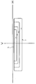
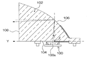
 図1は、本発明に係る車両用灯具の第1の実施の形態の構成を示した鉛直断面図である。図1に示す車両用灯具1は、例えば、自動車や自動二輪車等においてすれ違い光(ロービーム)用の配光パターンの照明光を照射するヘッドランプに適用されるもので、耐熱性の高い透明樹脂であるポリカーボネート材により射出形成されたレンズ体10(ライトガイド)と、LED光源30とを備えている。 FIG. 1 is a vertical sectional view showing the configuration of a first embodiment of a vehicular lamp according to the present invention. A vehicle lamp 1 shown in FIG. 1 is applied to a headlamp that emits illumination light having a light distribution pattern for passing light (low beam) in, for example, an automobile or a motorcycle, and is made of a transparent resin having high heat resistance. The lens body 10 (light guide) injection-molded with a certain polycarbonate material and the LED light source 30 are provided.
 レンズ体10は、例えば、入射面12を含む底面14と、車両後方側(灯具後方側)に配置される反射面16と、車両前方側に配置される出射面18と、車両上方側に配置される上面20と、車両側方両側に配置される図示しない2つの側面とで囲まれた立体形状に形成されている。 The lens body 10 is, for example, disposed on the bottom surface 14 including the incident surface 12, the reflecting surface 16 disposed on the vehicle rear side (lamp rear side), the emission surface 18 disposed on the vehicle front side, and the vehicle upper side. And a three-dimensional shape surrounded by two side surfaces (not shown) arranged on both sides of the vehicle.
 入射面12は、LED光源30から出射された光がレンズ体10内部に入射する入射面であり、水平方向(車両前後方向)に関して斜めに傾斜した平面により形成されている。底面14を構成する他の面は水平な平面で構成されている。 The incident surface 12 is an incident surface on which the light emitted from the LED light source 30 is incident on the inside of the lens body 10 and is formed by a plane inclined obliquely with respect to the horizontal direction (vehicle longitudinal direction). The other surface constituting the bottom surface 14 is a horizontal plane.
 反射面16は、LED光源30から出射されて入射面12を通過してレンズ体10内部に入射した光を予め定められた方向へ反射する。反射面16は、例えば、回転放物面系の形状を基調として形成されている。この反射面16は、その内面で上記入射光を全反射するように構成されていてもよいし、入射光が全反射されない部分等において反射面16の外面にアルミニウムなどの金属の反射膜等を形成して該反射膜によって反射させるようにしてもよい。 The reflection surface 16 reflects the light emitted from the LED light source 30 and passing through the incident surface 12 and entering the lens body 10 in a predetermined direction. The reflecting surface 16 is formed based on, for example, the shape of a rotating paraboloid system. The reflection surface 16 may be configured to totally reflect the incident light on its inner surface, or a metal reflection film such as aluminum is provided on the outer surface of the reflection surface 16 in a portion where the incident light is not totally reflected. It may be formed and reflected by the reflective film.
 出射面18は、反射面16からの反射光が出射する面であり、本実施の形態では車両前後方向に直交する鉛直方向の平面で形成されている。 The emission surface 18 is a surface from which the reflected light from the reflection surface 16 is emitted, and is formed by a vertical plane orthogonal to the vehicle longitudinal direction in this embodiment.
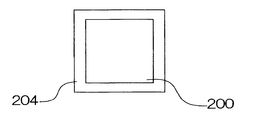
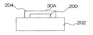
 LED光源30は、例えば、一つ又は複数のLEDチップをパッケージ化した白色光を出射する光源であり、光を放出する平面状の光放出面30Aが略鉛直方向上向きに配置されている。例えば、LEDチップとして青色発光のInGaN系のLEDチップを用い、図6A及び図6Bに示すように回路基板202に実装された当該LEDチップ200上に波長変化材料層204を平面状に設けたものを用いることができる。波長変換材料層204は、例えば、YAG(Yttrium Aluminum Garnet)蛍光体をシリコーン樹脂中に分散したものなどが用いられる。これによりLEDチップからの青色と、YAG蛍光体に波長変換された黄色(赤色成分および緑色成分を含む光)との混色により白色光を出射する。なお、光放出面30Aは平面状に限るものではなく、凸形状をなしたものでもよい。 The LED light source 30 is, for example, a light source that emits white light in which one or a plurality of LED chips are packaged, and a planar light emitting surface 30A that emits light is disposed substantially upward in the vertical direction. For example, an InGaN-based LED chip that emits blue light is used as the LED chip, and the wavelength change material layer 204 is provided in a planar shape on the LED chip 200 mounted on the circuit board 202 as shown in FIGS. 6A and 6B. Can be used. As the wavelength conversion material layer 204, for example, a YAG (Yttrium Aluminum Garnet) phosphor dispersed in a silicone resin is used. As a result, white light is emitted by a color mixture of blue from the LED chip and yellow (light including red and green components) wavelength-converted into a YAG phosphor. The light emitting surface 30A is not limited to a flat shape, and may be a convex shape.
 以上のごとく構成された車両用灯具1は、LED光源30から出射された光に対して、図2に示すようなすれ違い光用の配光パターンの照明光をレンズ体10を介して照射するように構成されている。図2には、車両用灯具1の真正面の方向に対して水平方向の角度を示すHラインと、鉛直方向の角度を示すVラインが示されている。図2の配光パターンは、Hラインより下向きとなる角度範囲内において、Vラインの左右両側に光が拡げられて照射される配光領域P(光度値が順に低減する領域P1~P4)を含んでいる。その配光領域Pの上端縁には、光が照射される明るい領域と、光が照射されない暗い領域との明暗境界を示す明暗境界線(カットオフライン)CLが水平方向に形成され、その明暗境界線CLは、Hラインの近傍(例えば、下向き0.57度)に形成される。ここで、本実施の形態の車両用灯具1が形成する配光パターンPは、図2の配光パターンの一部(例えば、領域P1~P4のいずれか)とする。なお、本実施の形態の車両用灯具1と同様に構成された灯具を縦方向や横方向などの所定方向に複数配列し、それら全体として図2の配光パターンを形成するようにしてもよい。 The vehicular lamp 1 configured as described above irradiates the light emitted from the LED light source 30 with illumination light having a light distribution pattern for passing light as shown in FIG. It is configured. FIG. 2 shows an H line indicating a horizontal angle with respect to a direction directly in front of the vehicular lamp 1 and a V line indicating an angle in the vertical direction. The light distribution pattern of FIG. 2 includes light distribution regions P (regions P1 to P4 in which light intensity values decrease in order) that are irradiated with light spread on both the left and right sides of the V line within an angle range downward from the H line. Contains. At the upper edge of the light distribution region P, a light-dark boundary line (cut-off line) CL indicating a light-dark boundary between a bright region irradiated with light and a dark region not irradiated with light is formed in the horizontal direction. The line CL is formed in the vicinity of the H line (for example, downward 0.57 degrees). Here, the light distribution pattern P formed by the vehicular lamp 1 of the present embodiment is a part of the light distribution pattern in FIG. 2 (for example, any one of the regions P1 to P4). Note that a plurality of lamps configured in the same manner as the vehicular lamp 1 of the present embodiment may be arranged in a predetermined direction such as a vertical direction or a horizontal direction, and the light distribution pattern of FIG. 2 may be formed as a whole. .
 ところで、上記車両用灯具1の光学設計を行う場合に、まず、LED光源30の光放出面30Aから各方向に放出される白色光線(可視光領域の波長からなる光線)に対して、図2の配光パターンが形成されるように、LED光源30とレンズ体10の位置関係や、それらの白色光線の目標の照射方向(白色光線をレンズ体10から出射する際の目標の出射方向)が決められる。そして、光放出面30Aから各方向に放出される各白色光線が目標の出射方向となるようにレンズ体10の入射面12、反射面16及び出射面18の形状が設定される。本実施の形態では、光放出面30Aのうち車両前後方向に関して最後端となる光放出点30Bが明暗境界線CLに拡大投影されることでカットオフラインを形成するように回転放物面形系の反射面16を設定している。最後端を明暗境界線CLとすれば、光放出面30Aのうち最前端からの放出光は明暗境界線CLより下側に向くことになり、Hラインより上向きのグレア光を生じないからである。 By the way, when the optical design of the vehicular lamp 1 is performed, first, with respect to white light rays (light rays having a wavelength in the visible light region) emitted in each direction from the light emission surface 30A of the LED light source 30, FIG. The positional relationship between the LED light source 30 and the lens body 10 and the target irradiation direction of those white light rays (the target emission direction when the white light rays are emitted from the lens body 10) It is decided. Then, the shapes of the entrance surface 12, the reflection surface 16, and the exit surface 18 of the lens body 10 are set so that each white light beam emitted from the light emitting surface 30A in each direction becomes the target exit direction. In the present embodiment, the light emitting point 30B, which is the rearmost end of the light emitting surface 30A in the vehicle front-rear direction, is enlarged and projected onto the light / dark boundary line CL so that a cut-off line is formed. A reflecting surface 16 is set. If the last end is the light / dark boundary line CL, the light emitted from the front end of the light emitting surface 30A is directed downward from the light / dark boundary line CL, and glare light upward from the H line is not generated. .
 その際、白色光線の入射面12や出射面18での入射角に対する屈折角は、レンズ体10の材料に応じた屈折率が用いられるとともに、光の波長によって屈折率が異なる場合には、特定の基準波長に対する屈折率(以下、基準屈折率という)が白色光線の波長全域(可視光領域)での一定の屈折率として近似的に用いられる。本実施の形態では、白色光線の波長領域の略中心波長である緑色の波長を基準波長、緑色の波長の屈折率を基準屈折率として、白色光線の波長全域に対して一定の基準屈折率を想定し、図2のような配光パターンが得られるようにレンズ体10の入射面12、反射面16及び出射面18の形状等の光学設計が行われるものとする。 At that time, the refractive angle with respect to the incident angle of the incident surface 12 or the exit surface 18 of the white light beam is determined according to the refractive index according to the material of the lens body 10 and specified when the refractive index varies depending on the wavelength of the light. The refractive index with respect to the reference wavelength (hereinafter referred to as the reference refractive index) is approximately used as a constant refractive index in the entire wavelength range of white light (visible light region). In this embodiment, a green wavelength, which is a substantially central wavelength in the wavelength region of white light, is set as a reference wavelength, and a refractive index of the green wavelength is set as a reference refractive index. Assume that the optical design such as the shapes of the incident surface 12, the reflecting surface 16, and the emitting surface 18 of the lens body 10 is performed so that a light distribution pattern as shown in FIG. 2 is obtained.
 一方、本実施の形態のようにレンズ体10を透明樹脂材料にて形成した場合、無機材料であるガラスレンズに比べて光の波長ごとの屈折率の違いが大きい。特に透明性、耐熱性および耐候性に優れたポリカーボネート材で形成した場合、ポリカーボネート材は光の波長ごとの屈折率の違いが大きく、色分散が大きいため、上記のように緑色の波長の屈折率を基準屈折率とし、白色光線の波長全域に対して一定の基準屈折率を想定して図2のような配光パターンが得られるように光学設計を行うと、図3のように明暗境界線CLの角度位置よりも上側に色分散による意図しない色分離した照明領域Qが形成されてしまう不具合が生じる。ここで、色分散とは、光の分散(dispersion of light)をいい、光がレンズ等に入射したとき、その波長によって屈折率が異なる現象をいう。 On the other hand, when the lens body 10 is formed of a transparent resin material as in the present embodiment, the difference in refractive index for each wavelength of light is larger than that of a glass lens that is an inorganic material. In particular, when formed from a polycarbonate material with excellent transparency, heat resistance, and weather resistance, the polycarbonate material has a large difference in refractive index for each wavelength of light and large color dispersion. If the optical design is made so that a light distribution pattern as shown in FIG. 2 is obtained assuming that the reference refractive index is a constant refractive index for the entire wavelength range of white light, a light / dark boundary line as shown in FIG. There arises a problem that an unintended color-separated illumination region Q is formed above the angle position of CL by color dispersion. Here, chromatic dispersion refers to dispersion of light (dispersion of light), and refers to a phenomenon in which, when light enters a lens or the like, the refractive index varies depending on the wavelength.
 即ち、上記レンズ体10は基本的にLED光源30の光放出面30Aを拡大投影することによって図2のような配光パターン(又はその一部)を形成するものである。従って、上記のように白色光線の波長全域に対して一定の基準屈折率を想定し、レンズ体10の色分散を考慮せずに図2の配光パターンが得られるように光学設計を行った場合、光放出面30Aのうち車両前後方向に関して最後端となる光放出点30Bがレンズ体10全体の焦点となるようにLED光源30の光放出面30Aとレンズ体10との位置関係が決定される。なお、レンズ体10全体の焦点とは、回転放物面系の反射面16の焦点位置について入射面12による屈折による影響を考慮して調整した焦点位置をいう。このとき、その光放出点30Bから各方向に放出された白色光線が、設計目標とする明暗境界線CLの角度方向に略平行な光線として照射される。そして、光放出点30Bより車両前方側の光放出面30Aの各点から放出された白色光線が、設計目標の明暗境界線CLよりも下側の角度範囲を照明するように設計される。 That is, the lens body 10 basically forms a light distribution pattern (or a part thereof) as shown in FIG. 2 by enlarging and projecting the light emitting surface 30A of the LED light source 30. Accordingly, the optical design was performed so that the light distribution pattern of FIG. 2 can be obtained without considering the chromatic dispersion of the lens body 10 assuming a constant reference refractive index for the entire wavelength range of white light as described above. In this case, the positional relationship between the light emitting surface 30A of the LED light source 30 and the lens body 10 is determined so that the light emitting point 30B which is the rearmost end in the vehicle longitudinal direction of the light emitting surface 30A is the focal point of the entire lens body 10. The The focal point of the entire lens body 10 refers to a focal position that is adjusted in consideration of the influence of refraction by the incident surface 12 with respect to the focal position of the reflecting surface 16 of the paraboloidal system. At this time, the white light beam emitted in each direction from the light emission point 30B is irradiated as a light beam substantially parallel to the angular direction of the light / dark boundary line CL which is the design target. The white light beam emitted from each point of the light emission surface 30A on the vehicle front side from the light emission point 30B is designed to illuminate an angular range below the design target light / dark boundary line CL.
 このとき、レンズ体10の色分散を考慮すると、光放出点30Bから放出された白色光線のうち、入射面12と出射面18の両方で屈折しない光路を通過するものは、設計目標の明暗境界線CLの角度方向に照射される。一方、入射面12又は出射面18で屈折する光路を通過するものについては、基準屈折率として用いた緑色の波長の光線(緑色の光線)以外の波長の光線、即ち、その緑色の波長より長波長側又は短波長側の赤色や青色の光線がそれらの波長の実際の屈折率が基準屈折率と相違するため、レンズ体10の屈折が生じる面で緑色の光線とは異なる方向に分離される。その結果、赤色や青色の光線の一部が設計目標とした明暗境界線CLよりも上向きの角度方向に照射され、明暗境界線CLの上側に色収差(色にじみ)を生じさせ、明暗境界線CLの上側に図3のような意図しない照明領域Qを形成する。 At this time, in consideration of the chromatic dispersion of the lens body 10, among the white light rays emitted from the light emission point 30 </ b> B, those passing through an optical path that is not refracted by both the entrance surface 12 and the exit surface 18 Irradiation is in the angle direction of the line CL. On the other hand, the light passing through the optical path refracted on the incident surface 12 or the light exit surface 18 is a light beam having a wavelength other than the green light beam (green light beam) used as the reference refractive index, that is, longer than the green wavelength. The red or blue light rays on the wavelength side or the short wavelength side are separated in a direction different from the green light rays on the surface where the refraction of the lens body 10 occurs because the actual refractive index of those wavelengths is different from the reference refractive index. . As a result, a part of red and blue light rays are irradiated in an upward angle direction with respect to the light / dark boundary line CL which is the design target, causing chromatic aberration (color blur) above the light / dark boundary line CL, and the light / dark boundary line CL. An unintended illumination region Q as shown in FIG.
 そこで、本実施の形態では、上記のように白色光線の波長全域に対して一定の基準屈折率を想定して色分散を考慮せずに設計される車両用灯具1の基本的な構成、即ち、LED光源30とレンズ体10との位置関係やレンズ体10の構成等(入射面12、反射面16及び出射面38の形状等)に対して、以下のように光放出面30Aの光放出点30Bから放出された白色光線について色分散(波長ごとの屈折率の相違)を考慮し、明暗境界線CLの上側に色収差(意図しない照明領域Q)が生じないようにレンズ体10の入射面12、反射面16及び出射面18の形状に調整(補正)が施されている。 Therefore, in the present embodiment, as described above, the basic configuration of the vehicular lamp 1 designed without considering chromatic dispersion assuming a constant reference refractive index for the entire wavelength range of white light, that is, With respect to the positional relationship between the LED light source 30 and the lens body 10, the configuration of the lens body 10, etc. (shapes of the incident surface 12, the reflective surface 16, and the exit surface 38), In consideration of chromatic dispersion (difference in refractive index for each wavelength) with respect to white light emitted from the point 30B, the incident surface of the lens body 10 does not cause chromatic aberration (unintended illumination region Q) above the light-dark boundary line CL. 12, the shapes of the reflecting surface 16 and the emitting surface 18 are adjusted (corrected).
 尚、ポリカーボネート材は、白色光線の波長領域(可視光の波長領域)である約380~780nmの範囲において、波長が長くなるほど屈折率が小さくなるという特性を有している。例えば、青色の波長435.8nmに対するポリカーボネート材の屈折率は1.6115、緑色の波長546.1nmに対するポリカーボネート材の屈折率は1.5855、青色の波長706.5nmに対するポリカーボネート材の屈折率は1.576である。このとき、レンズ体10の入射面12、反射面16及び出射面18の基本的形状の設計時には、例えば、基準波長の光として緑色の光(波長546.1nm)が用いられ、基準屈折率が1.5855に設定される。また、レンズ体10の色分散の問題に対して考慮すべき光の波長範囲のうち、最も長い波長を、例えば、上記赤色の光の波長(706.5nm)として、最も短い波長を、例えば、上記青色の光の波長(435.8nm)としてレンズ体10の入射面12、反射面16及び出射面18の基本的形状に対する調整が施されるものとする。以下において、緑色の光線、赤色の光線、青色の光線のように色を指定して記載する光は、上記に列挙した波長の光を示すものとする。ただし、これらの具体的に示した各波長の値は適宜変更可能である。 The polycarbonate material has a characteristic that the refractive index decreases as the wavelength increases in the range of about 380 to 780 nm, which is the wavelength region of white light (visible light wavelength region). For example, the refractive index of a polycarbonate material for a blue wavelength of 435.8 nm is 1.6115, the refractive index of a polycarbonate material for a green wavelength of 546.1 nm is 1.5855, and the refractive index of the polycarbonate material for a blue wavelength of 706.5 nm is 1. .576. At this time, when designing the basic shapes of the entrance surface 12, the reflection surface 16, and the exit surface 18 of the lens body 10, for example, green light (wavelength 546.1 nm) is used as the reference wavelength light, and the reference refractive index is Set to 1.5855. In addition, among the wavelength range of light to be considered for the problem of chromatic dispersion of the lens body 10, the longest wavelength is, for example, the wavelength of red light (706.5 nm), and the shortest wavelength is, for example, It is assumed that the basic shape of the entrance surface 12, the reflection surface 16, and the exit surface 18 of the lens body 10 is adjusted as the wavelength of the blue light (435.8 nm). In the following, light described by designating colors such as green light, red light, and blue light shall indicate light having the wavelengths listed above. However, the values of these specific wavelengths can be changed as appropriate.
 また、本実施の形態では、レンズ体10の入射面12、反射面16及び出射面18の基本的な形状に対する調整は、反射面16の調整のみによって行われたものである。即ち、入射面12及び出射面18の形状はいずれも基準屈折率を想定して図2の配光パターンが得られるように設計された際の面形状(平面)に固定され、反射面16には、例えば、基本的な形状として求められた回転放物面に対して調整が施される。 In the present embodiment, the basic shapes of the entrance surface 12, the reflection surface 16, and the exit surface 18 of the lens body 10 are adjusted only by adjusting the reflection surface 16. That is, the shapes of the entrance surface 12 and the exit surface 18 are both fixed to the surface shape (plane) when designed so as to obtain the light distribution pattern of FIG. Is adjusted, for example, with respect to the paraboloid obtained as a basic shape.
 更に、本実施の形態のレンズ体10の出射面18は、上記のように略鉛直方向の平面で形成されている。反射面16から明暗境界線CLの近傍方向に反射される光は略水平に照射するものであるから出射面18による屈折は小さく、色分散の程度も小さくなる。そこで、説明を簡単にするために、出射面18により色分散および色分離が生じないものとし、出射面18から出射される光線の方向は、反射面16で反射された光線の方向に等しいものとする。 Furthermore, the exit surface 18 of the lens body 10 of the present embodiment is formed as a substantially vertical plane as described above. Since the light reflected from the reflecting surface 16 in the vicinity of the light-dark boundary line CL is irradiated substantially horizontally, the refraction by the emitting surface 18 is small and the degree of chromatic dispersion is also small. Therefore, for the sake of simplicity, it is assumed that color dispersion and color separation are not caused by the exit surface 18, and the direction of the light beam emitted from the exit surface 18 is equal to the direction of the light beam reflected by the reflective surface 16. And
 以下、レンズ体10の形状調整について説明する。図1のレンズ体10は、明暗境界線CLの上側に意図しない照明領域Qが生じないように色分散(波長ごとの屈折率の相違)が考慮されてレンズ体10の反射面16の形状に調整(補正)が施されたものであり、図1には、LED光源30の最後端の光放出点30Bから放出された白色光線のうち、入射面12に垂直に入射(入射角0度)する白色光線X1と、その白色光線X1より車両前方側と車両後方側で入射面12に斜めに入射する白色光線X2、X3の基本屈折率での光路(白色光線の波長全域で屈折率が一定の基本屈折率とした場合の光路)が実線で例示されている。図1に示すように、LED光源30の光放出点30Bから放出された各々の白色光線X1、X2、X3は、入射面12からレンズ体10内部に進入し、反射面16で反射された後、出射面18からレンズ体10外部に照射される。図1において、白色光線の波長全域に対して一定の基準屈折率を想定し、色分散を考慮しない場合の白色光線X1、X2およびX3に対応する光路を一点鎖線にて光路CLD1、CLD2およびCLD3として記載している。CLD1はX1と同一光路であり、CLD2およびCLD3はCLD1と平行な光線を出射面18から外部に照射するものとしている。このような光路CLD1、CLD2およびCLD3は、反射面16として光放出点30B(厳密には、入射面12による屈折を考慮した30Bよりも僅かに図面斜め左下方向の位置)の位置を焦点とした回転放物面反射面とすることにより得ることができる。この形状を基本的形状とする。尚、一点鎖線で示す光路CLD1、CLD2、CLD3は、白色光線X1、X2、X3を設計目標の明暗境界線CLの角度方向に出射面18から出射されるための光路を示し、上記のように明暗境界線CLの近傍方向への光線は出射面18で屈折しないため、それらの光路CLD1、CLD2、CLD3は、反射面16の位置から出射面18を介したレンズ体10外部まで直線で示される。 Hereinafter, the shape adjustment of the lens body 10 will be described. The lens body 10 in FIG. 1 has a shape of the reflecting surface 16 of the lens body 10 in consideration of chromatic dispersion (difference in refractive index for each wavelength) so that an unintended illumination region Q does not occur above the light / dark boundary line CL. In FIG. 1, white light emitted from the light emission point 30 </ b> B at the rearmost end of the LED light source 30 is incident on the incident surface 12 perpendicularly (incidence angle 0 degree). And a light path with a basic refractive index of white light rays X2 and X3 obliquely incident on the incident surface 12 on the vehicle front side and the vehicle rear side with respect to the white light beam X1 (the refractive index is constant over the entire wavelength range of the white light beam). The optical path in the case of the basic refractive index is illustrated by a solid line. As shown in FIG. 1, each white light beam X <b> 1, X <b> 2, X <b> 3 emitted from the light emission point 30 </ b> B of the LED light source 30 enters the lens body 10 from the incident surface 12 and is reflected by the reflecting surface 16. The lens body 10 is irradiated from the exit surface 18. In FIG. 1, assuming a constant reference refractive index for the entire wavelength range of white light rays, the optical paths corresponding to the white light rays X1, X2 and X3 in the case where chromatic dispersion is not taken into consideration are shown as the optical paths CLD1, CLD2 and CLD3. It is described as. CLD1 has the same optical path as X1, and CLD2 and CLD3 irradiate light beams parallel to CLD1 from the exit surface 18 to the outside. Such optical paths CLD1, CLD2, and CLD3 are focused on the position of the light emission point 30B as the reflecting surface 16 (strictly, the position in the slightly lower left direction of the drawing 30B considering refraction by the incident surface 12). It can be obtained by using a paraboloidal reflecting surface. This shape is a basic shape. The optical paths CLD1, CLD2, and CLD3 indicated by alternate long and short dash lines indicate the optical paths for emitting the white light rays X1, X2, and X3 from the emission surface 18 in the angular direction of the design target bright / dark boundary line CL, as described above. Since light rays in the vicinity of the light / dark boundary line CL are not refracted at the exit surface 18, their optical paths CLD 1, CLD 2, and CLD 3 are shown as straight lines from the position of the reflective surface 16 to the outside of the lens body 10 via the exit surface 18. .
 これに対して、本実施の形態のレンズ体10においては、色分散が考慮されて反射面16の形状が設定されている。即ち、入射面12に垂直に入射し、レンズ体10の入射面12及び出射面18で屈折が生じない白色光線X1については、目標の照射方向が、上記と変更なく設計目標の明暗境界線CLの角度方向に設定される。図1のように、反射面16の位置T1に入射した白色光線X1が光路CLD1に沿った明暗境界線CLの角度方向に反射するように位置T1での反射面16の形状(位置及び傾き)が基本的形状と一致したものに形成されている。尚、入射面12で屈折が生じない白色光線X1が反射する反射面16の位置T1は、反射面16の上下方向の範囲のうちの略中央となるように入射面12の角度が設定されている。これによって、反射面16で反射する全ての光線の入射面12における入射角(屈折角)の大きさが、できるだけ小さくなるように考慮されており、色分散の発生が低減されている。すなわち、位置T1は、入射面12で屈折が生じない非屈折光路の反射部であり、上記した基本的形状と一致する。 In contrast, in the lens body 10 of the present embodiment, the shape of the reflecting surface 16 is set in consideration of chromatic dispersion. That is, for the white light beam X1 that is perpendicularly incident on the incident surface 12 and is not refracted at the incident surface 12 and the exit surface 18 of the lens body 10, the target irradiation direction is the design target light / dark boundary line CL without any change. Is set in the angle direction. As shown in FIG. 1, the shape (position and inclination) of the reflecting surface 16 at the position T1 is such that the white light beam X1 incident on the position T1 of the reflecting surface 16 is reflected in the angular direction of the light / dark boundary line CL along the optical path CLD1. Is formed in accordance with the basic shape. In addition, the angle of the incident surface 12 is set so that the position T1 of the reflective surface 16 where the white light ray X1 that does not cause refraction at the incident surface 12 is reflected is approximately the center of the range in the vertical direction of the reflective surface 16. Yes. As a result, the incident angle (refractive angle) of all light rays reflected by the reflecting surface 16 on the incident surface 12 is considered to be as small as possible, and the occurrence of chromatic dispersion is reduced. That is, the position T1 is a reflection part of a non-refractive optical path where refraction does not occur on the incident surface 12, and coincides with the basic shape described above.
 一方、白色光線X1よりも車両前方側又は車両後方側に入射面12に入射し、入射面12で屈折が生じる白色光線(白色光線X2、X3)については、その屈折により生じる色分散(色分離)の大きさに応じて目標の照射方向が、設計目標の明暗境界線CLよりも下向きの角度方向に設定される。図1のように白色光線の波長全域に対して一定の基準屈折率を想定した場合において、反射面16の位置T1より上側と下側の位置T2、T3に入射した白色光線X2、X3(即ち、緑色の光線)が明暗境界線CLの角度方向(光路CLD2、CLD3)よりも下向きの角度方向に照射(反射)されるように反射面16の形状が設計されている。 On the other hand, with respect to white light rays (white light rays X2 and X3) that are incident on the incident surface 12 toward the vehicle front side or vehicle rear side with respect to the white light ray X1 and are refracted at the incident surface 12, color dispersion (color separation) caused by the refraction. The target irradiation direction is set to an angle direction downward from the design target light / dark boundary line CL. Assuming that a constant reference refractive index is assumed for the entire wavelength range of white light as shown in FIG. 1, white light rays X2 and X3 (that is, incident on positions T2 and T3 above and below the position T1 of the reflecting surface 16 (ie, The shape of the reflecting surface 16 is designed so that the green light rays are irradiated (reflected) in the angular direction downward from the angular direction of the light-dark boundary line CL (optical paths CLD2, CLD3).
 尚、基本的形状の反射面に対して補正を加えて本実施の形態の反射面16を設計する方法として、例えば、基本的形状の反射面に対して補正を加えない位置T1を基準点にして基準点より上側に順に反射面上の点を補正点として設定していくものとする。そして、ある補正点において、反射面16の傾きが、その補正点に入射した白色光線を補正後の目標の照射方向に反射させるような傾きとなるように補正すると共に、その傾きの補正分の回転を補正点よりも上側の反射面全体に全体加えることによって補正点よりも上側の反射面全体の各点の位置及び傾きをその全体形状を変更することなく補正する。この後、新たな補正点を補正した反射面上に設定して、同じ操作を繰り返す。また、位置T1よりも下側の反射面にも同様の操作を繰り返す、というような方法が考えられる、ただし、本実施の形態の反射面16を設計する方法についてはこれに限らない。 As a method of designing the reflecting surface 16 of the present embodiment by correcting the reflecting surface of the basic shape, for example, a position T1 where no correction is applied to the reflecting surface of the basic shape is used as a reference point. Assume that points on the reflecting surface are set as correction points in order above the reference point. Then, at a certain correction point, the inclination of the reflecting surface 16 is corrected so as to reflect the white light incident on the correction point in the corrected target irradiation direction, and the correction amount of the inclination is corrected. By applying rotation to the entire reflecting surface above the correction point, the position and inclination of each point on the entire reflecting surface above the correction point are corrected without changing the overall shape. Thereafter, a new correction point is set on the corrected reflection surface, and the same operation is repeated. A method of repeating the same operation on the reflective surface below the position T1 is conceivable. However, the method of designing the reflective surface 16 of the present embodiment is not limited to this.
 ここで、本実施の形態のレンズ体10のように色分散を考慮して反射面16の形状を設計した場合に、LED光源30の光放出点30Bから放出された白色光線X1、X2、X3がレンズ体10を介して実際にどのように照射されるかについて具体的に説明する。 Here, when the shape of the reflecting surface 16 is designed in consideration of chromatic dispersion as in the lens body 10 of the present embodiment, white light rays X1, X2, and X3 emitted from the light emission point 30B of the LED light source 30 are designed. Will be described in detail as to how the lens is actually irradiated through the lens body 10.
 まず、入射面12に垂直に入射する白色光線X1は、入射面12において屈折しないため、そのまま色分散(色分離)を生じることなく、レンズ体10内部を進行し、反射面16の位置T1に入射する。そして、その反射面16に入射した白色光線X1は、光路CLD1に沿った方向に反射され、設計目標の明暗境界線CLの角度方向に照射(出射面18から出射)される。図1の白色光線X1、X2、X3の光路は、白色光線の波長全域で一定の基準屈折率と想定した場合の光路であり、基準屈折率は、緑色の光線の屈折率である。このため、白色光線X1に含まれる緑色の光線G1は、屈折の有無に関係なく、図1に示した白色光線X1と同じ光路を通過して設計目標の明暗境界線CLの角度方向に照射される。また、白色光線X1に含まれる緑色の波長以外の赤色や青色のような光線も入射面12(及び出射面18)での屈折が生じないため、色分離されることなく、白色光線X1と同じ光路を通過して設計目標の明暗境界線CLの角度方向に照射される。従って、光放出点30Bから出射され、入射面12に対して垂直に入射する白色光線X1は、白色のまま設計目標の明暗境界線CLの角度方向に照射され、白色の明暗境界線CLを形成する。 First, since the white light ray X1 incident perpendicularly to the incident surface 12 is not refracted at the incident surface 12, the white light beam X1 travels through the lens body 10 without causing chromatic dispersion (color separation) as it is, and reaches the position T1 of the reflecting surface 16. Incident. The white light beam X1 incident on the reflecting surface 16 is reflected in the direction along the optical path CLD1, and is irradiated (emitted from the emitting surface 18) in the angular direction of the design target light / dark boundary line CL. The optical paths of the white light beams X1, X2, and X3 in FIG. 1 are optical paths when assuming a constant reference refractive index over the entire wavelength range of the white light beams, and the reference refractive index is the refractive index of the green light beam. For this reason, the green light ray G1 included in the white light ray X1 passes through the same optical path as the white light ray X1 shown in FIG. 1 regardless of the presence or absence of refraction, and is irradiated in the angular direction of the light / dark boundary line CL of the design target. The In addition, light rays such as red and blue other than the green wavelength included in the white light beam X1 are not refracted at the incident surface 12 (and the output surface 18), and thus are not separated and are the same as the white light beam X1. The light passes through the optical path and is irradiated in the angular direction of the light / dark boundary line CL which is the design target. Accordingly, the white light beam X1 emitted from the light emission point 30B and perpendicularly incident on the incident surface 12 is irradiated in the angular direction of the light / dark boundary line CL as a design target while being white, thereby forming a white light / dark boundary line CL. To do.
 一方、入射面12に対して車両前方側から斜めに入射する白色光線X2は、入射面12に入射すると、屈折を生じ色分散によりレンズ体10内部において色分離を起こす。このとき、レンズ体10内部において、白色光線X2に含まれる緑色の光線G2は、一定の基準屈折率を想定した場合の白色光線X2と同じ光路を進行して反射面16の位置T2に入射する。そして、反射面16により光路CLD2よりも下向きの角度方向に反射され、設計目標の明暗境界線CLの角度方向よりも下向きの角度方向に照射される。 On the other hand, when the white light beam X2 obliquely incident on the incident surface 12 from the front side of the vehicle is incident on the incident surface 12, refraction occurs and color separation occurs inside the lens body 10 due to chromatic dispersion. At this time, in the lens body 10, the green light ray G2 included in the white light ray X2 travels along the same optical path as the white light ray X2 when a constant reference refractive index is assumed, and enters the position T2 of the reflecting surface 16. . Then, the light is reflected by the reflecting surface 16 in the downward angular direction with respect to the optical path CLD2, and is irradiated in the downward angular direction with respect to the angular direction of the light / dark boundary line CL which is the design target.
 これに対して、白色光線X2に含まれる赤色の光線R2(点線)は、基準屈折率(緑色の波長の屈折率)よりも屈折率が小さいため、入射面12において、緑色の光線G2よりも小さな屈折角で屈折し、白色光線X2の光路(緑色の光線G2の光路)よりも車両前方側となる角度方向の光路を進行し、反射面16の位置T2の近傍(上側)に入射する。そして、その赤色の光線R2は、反射面16への入射角が白色光線X2(緑色の光線G2)よりも大きくなるため、白色光線X2(緑色の光線G2)よりも上向きの角度方向に反射される。このとき、赤色の光線R2が白色光線X2(緑色の光線G2)に対してどの程度上向きの角度方向に反射されるかが考慮されて、赤色の光線R2が設計目標の明暗境界線CLより上向きの角度方向に照射されないように白色光線X2(緑色の光線G2)の目標の照射方向が設定され、反射面16の形状が設定されているため、赤色の光線R2は、光路CLD2に略沿った角度方向、又は、光路CLD2よりも下向きの角度方向に反射面16で反射される。これにより、赤色の光線R2が、設計目標の明暗境界線CLよりも上向きとならない角度方向に出射面18から出射される。 On the other hand, since the red light ray R2 (dotted line) included in the white light ray X2 has a refractive index smaller than the reference refractive index (refractive index of the green wavelength), the incident surface 12 has a lower refractive index than the green light ray G2. The light beam is refracted at a small refraction angle, travels along the optical path in the angular direction that is on the vehicle front side of the optical path of the white light beam X2 (the optical path of the green light beam G2), and enters the vicinity (upper side) of the reflective surface 16 at the position T2. And since the incident angle to the reflecting surface 16 becomes larger than the white light ray X2 (green light ray G2), the red light ray R2 is reflected in the upward angle direction than the white light ray X2 (green light ray G2). The At this time, considering how much the red light ray R2 is reflected in the upward angular direction with respect to the white light ray X2 (green light ray G2), the red light ray R2 is upward from the light / dark boundary line CL of the design target. Since the target irradiation direction of the white light beam X2 (green light beam G2) is set and the shape of the reflecting surface 16 is set so that the light beam R2 is not irradiated in the angular direction of the red light beam R2, the red light beam R2 substantially follows the optical path CLD2. The light is reflected by the reflecting surface 16 in the angular direction or in an angular direction downward from the optical path CLD2. As a result, the red light ray R2 is emitted from the emission surface 18 in an angular direction that is not upward from the design target light / dark boundary line CL.
 尚、白色光線X2に含まれる図示しない青色の光線についても入射面12で分離され、図1に示す白色光線X2(緑色の光線G2)と異なる光路を通過する。ただし、赤色の光線R2とは反対に白色光線X2(緑色の光線G2)よりも下向きの角度方向に出射面18から出射されるため、赤色の光線R2が、設計目標の明暗境界線CLよりも上向きとならない角度方向に照射されることによって、青色の光線も必然的に設計目標の明暗境界線CLよりも上向きとならない角度方向に照射される。 Note that a blue light beam (not shown) included in the white light beam X2 is also separated by the incident surface 12, and passes through a different optical path from the white light beam X2 (green light beam G2) shown in FIG. However, since the red light ray R2 is emitted from the emission surface 18 in the downward angle direction with respect to the white light ray X2 (green light ray G2) as opposed to the red light ray R2, the red light ray R2 is more than the light / dark boundary line CL of the design target. By irradiating in an angular direction that does not face upward, blue light is inevitably emitted in an angular direction that does not face upward from the design target light / dark boundary line CL.
 また、入射面12に対して車両後方側から斜めに入射する白色光線X3は、入射面12に入射すると、屈折を生じ色分散によりレンズ体10内部において色分離を起こす。このとき、レンズ体10内部において、白色光線X3に含まれる緑色の光線G3は、一定の基準屈折率を想定した場合の白色光線X3と同じ光路を進行して反射面16の位置T3に入射する。そして、反射面16により光路CLD3よりも下向きの角度方向に反射され、設計目標の明暗境界線CLの角度方向よりも下向きの角度方向に照射される。 Further, when the white light beam X3 obliquely incident on the incident surface 12 from the rear side of the vehicle is incident on the incident surface 12, refraction occurs and color separation occurs inside the lens body 10 due to chromatic dispersion. At this time, in the lens body 10, the green light ray G3 included in the white light ray X3 travels along the same optical path as the white light ray X3 when a constant reference refractive index is assumed, and is incident on the position T3 of the reflecting surface 16. . Then, the light is reflected by the reflecting surface 16 in the downward angle direction with respect to the optical path CLD3 and irradiated in the downward angle direction with respect to the angular direction of the light / dark boundary line CL which is the design target.
 これに対して、白色光線X3に含まれる青色の光線B3(点線)は、基準屈折率(緑色の波長の屈折率)よりも屈折率が大きいため、入射面12において、緑色の光線G3よりも大きな屈折角で屈折し、白色光線X3の光路(緑色の光線G3の光路)よりも車両前方側となる角度方向の光路を進行し、反射面16の位置T3の近傍(上側)に入射する。そして、その青色の光線B3は、反射面16への入射角が白色光線X3(緑色の光線G3)よりも大きくなるため、白色光線X3(緑色の光線G3)よりも上向きの角度方向に反射される。このとき、青色の光線B3が白色光線X3(緑色の光線G3)に対してどの程度上向きの角度方向に反射されるかが考慮されて、青色の光線B3が設計目標の明暗境界線CLより上向きの角度方向に照射されないように白色光線X3(緑色の光線G3)の目標の照射方向が設定され、反射面16の形状が設定される。このため、青色の光線B3は、光路CLD3に略沿った角度方向、又は、光路CLD3よりも下向きの角度方向に反射面16で反射される。これにより、青色の光線B3が、設計目標の明暗境界線CLよりも上向きとならない角度方向に出射面18から出射される。 On the other hand, since the blue light ray B3 (dotted line) included in the white light ray X3 has a refractive index larger than the reference refractive index (refractive index of the green wavelength), the incident surface 12 has a higher refractive index than the green light ray G3. The light beam is refracted at a large refraction angle, travels along an optical path in the angular direction that is on the vehicle front side of the optical path of the white light beam X3 (the optical path of the green light beam G3), and enters the vicinity (upper side) of the position T3 of the reflecting surface 16. The blue light ray B3 is reflected in an angle direction upward from the white light ray X3 (green light ray G3) because the angle of incidence on the reflecting surface 16 is larger than that of the white light ray X3 (green light ray G3). The At this time, considering how much the blue light ray B3 is reflected in the upward angular direction with respect to the white light ray X3 (green light ray G3), the blue light ray B3 is directed upward from the light / dark boundary line CL of the design target. The target irradiation direction of the white light beam X3 (green light beam G3) is set so as not to be irradiated in the angular direction, and the shape of the reflection surface 16 is set. For this reason, the blue light beam B3 is reflected by the reflecting surface 16 in an angular direction substantially along the optical path CLD3 or in an angular direction downward from the optical path CLD3. As a result, the blue light beam B3 is emitted from the emission surface 18 in an angular direction that is not upward from the design target light / dark boundary line CL.
 尚、白色光線X3に含まれる図示しない赤色の光線は、入射面12で分離され、図1に示す白色光線X3(緑色の光線G3)と異なる光路を通過する。そして、該赤色光線は、青色の光線B3とは反対に白色光線X3(緑色の光線G3)よりも下向きの角度方向に出射面18から出射される。このため、青色の光線B3が、設計目標の明暗境界線CLよりも上向きとならない角度方向に照射されることによって、赤色の光線も必然的に設計目標の明暗境界線CLよりも上向きとならない角度方向に照射される。 Note that a red light beam (not shown) included in the white light beam X3 is separated by the incident surface 12, and passes through an optical path different from that of the white light beam X3 (green light beam G3) shown in FIG. Then, the red light beam is emitted from the emission surface 18 in the angular direction downward from the white light beam X3 (green light beam G3), opposite to the blue light beam B3. For this reason, the blue light ray B3 is irradiated in an angular direction that does not face upward from the light / dark boundary line CL of the design target, so that the red light light inevitably does not face upward from the light / dark boundary line CL of the design target. Irradiated in the direction.
 以上のように、本実施の形態の車両用灯具1によれば、LED光源30の光放出点30Bから各方向に放出された白色光線のうち、レンズ体10において、屈折が生じず、色分散(色分離)が生じない光路を通過する白色光線X1のような光線については、明暗境界線CLの角度方向に照射され、白色光によって明瞭な明暗境界線CLが形成される。また、この白色光線X1による明暗境界線CLの形成によって、明暗境界線CLの色度が白色の範囲に保持される。 As described above, according to the vehicular lamp 1 of the present embodiment, among the white light rays emitted in the respective directions from the light emission point 30B of the LED light source 30, no refraction occurs in the lens body 10 and color dispersion occurs. A light beam such as the white light beam X1 passing through an optical path where no (color separation) occurs is irradiated in the angle direction of the light / dark boundary line CL, and a clear light / dark boundary line CL is formed by the white light. Further, the formation of the light / dark boundary line CL by the white light beam X1 maintains the chromaticity of the light / dark boundary line CL in the white range.
 一方、屈折が生じ、色分散が生じる光路を通過する白色光線X2、X3については、白色光線の波長全域において一定の基準屈折率を想定した場合の目標の照射方向(緑色の光線の照射方向)が、明暗境界線CLよりも下向きの角度方向に設定される。これにより、色分散により緑色の光線よりも上向きの角度方向に照射される赤色や青色の光線が明暗境界線CLよりも下向きの角度方向に照射される。即ち、色分離した波長域の光は明暗境界線CLの下側の配光パターン内を照射する。配光パターン内において光放出点30B以外の箇所からの照射光等と混色される。従って、明暗境界線CLの上側に色分散による意図しない照明領域Qが発生する不具合が防止される。 On the other hand, for the white light rays X2 and X3 passing through the optical path where refraction occurs and chromatic dispersion occurs, the target irradiation direction (irradiation direction of the green light beam) assuming a constant reference refractive index in the entire wavelength range of the white light rays Is set in an angle direction downward from the light-dark boundary line CL. As a result, red or blue light rays radiated in an upward angle direction with respect to the green light rays due to chromatic dispersion are radiated in an angle direction downward with respect to the light / dark boundary line CL. That is, the light of the wavelength region that is color-separated irradiates the light distribution pattern below the light / dark boundary line CL. In the light distribution pattern, the light is mixed with irradiation light or the like from a place other than the light emission point 30B. Therefore, a problem that an unintended illumination region Q due to color dispersion occurs above the light / dark boundary line CL is prevented.
 また、光源として波長変換材料を用いたLED光源を用いて明暗境界を形成する場合、LEDチップから照射される光束を遮光することなく、できる限り有効に利用して明暗境界を形成するのがエネルギー利用効率の点からも好適である。それゆえ、LED光源の端部を明暗境界、特にすれ違い配光用のヘッドランプのHライン近傍の明暗境界線CLとして利用するのが好ましい。この場合、LED光源は図6に示したようにLED端部にまで波長変換材料層を設けているため、LED光源端部においては中央部に比べて色むらが生じやすい。このことは、LED光源をレンズ体にて拡大投影する場合において、明暗境界線CLにLED光源の色むらをそのまま投影する潜在的な問題点を有することになる。本実施形態においては、上述したように明暗境界線CLに色分散を考慮したレンズ体としているので、LED光源の端部における色むらが生じている場合でも、色むらを低減することが可能となる。 In addition, when an LED light source using a wavelength conversion material as a light source is used to form a light / dark boundary, it is energy to form the light / dark boundary by using it as effectively as possible without shielding the light flux emitted from the LED chip. It is also preferable from the viewpoint of utilization efficiency. Therefore, it is preferable to use the end portion of the LED light source as a light / dark boundary, in particular, as a light / dark boundary line CL in the vicinity of the H line of the headlamp for passing light distribution. In this case, since the LED light source is provided with the wavelength conversion material layer up to the LED end as shown in FIG. 6, color unevenness is more likely to occur at the LED light source end than at the center. This has the potential problem of projecting the color unevenness of the LED light source as it is onto the light / dark boundary line CL when the LED light source is enlarged and projected by the lens body. In the present embodiment, as described above, the lens body considering the chromatic dispersion in the light / dark boundary line CL is used. Therefore, even when the color unevenness occurs at the end of the LED light source, the color unevenness can be reduced. Become.
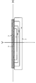
 図4は、本発明に係る車両用灯具の第2の実施の形態の構成を示した鉛直断面図である。図1の第1の実施の形態の車両用灯具1と同一又は類似の要素には同一符号又はプライム記号を付している。図4の車両用灯具50は、図1の車両用灯具1と比較して、入射面12′の形状が相違している。図4の車両用灯具50の入射面12′は、平面ではなく凹面に形成されている。図4の車両用灯具50のその他の構成要素については第1の実施の形態の車両用灯具1と同様に構成され、図2の配光パターンを形成するようにレンズ体10の反射面16′の形状が形成されている。 FIG. 4 is a vertical sectional view showing the configuration of the second embodiment of the vehicular lamp according to the present invention. Elements that are the same as or similar to those in the vehicular lamp 1 of the first embodiment in FIG. 4 is different from the vehicle lamp 1 of FIG. 1 in the shape of the incident surface 12 '. The incident surface 12 ′ of the vehicular lamp 50 in FIG. 4 is not a flat surface but a concave surface. The other components of the vehicular lamp 50 of FIG. 4 are configured in the same manner as the vehicular lamp 1 of the first embodiment, and the reflecting surface 16 ′ of the lens body 10 is formed so as to form the light distribution pattern of FIG. The shape is formed.
 入射面12′は、例えば、図4の鉛直断面図上において、入射面12′に対してLED光源30の光放出点30Bよりも離れた位置を中心52とする円弧状(LED光源30の光放出点30Bを中心とする円弧よりも曲率半径が大きい円弧)に形成される。更に、入射面12′の円弧の中心52が、光放出点30Bと反射面16′の中央付近の位置T1′とを通る直線上に位置するような円弧の凹面で形成されている。従って、光放出点30Bから各方向に放出された白色光線が入射面12′に入射する際の入射角が第1の実施の形態の車両用灯具1の場合よりも全体的に小さく、入射面12′での屈折による色分散が小さくなっている。 The incident surface 12 'is, for example, in the shape of a circular arc (light from the LED light source 30) centered at a position away from the light emission point 30B of the LED light source 30 with respect to the incident surface 12' on the vertical sectional view of FIG. An arc having a larger radius of curvature than an arc centered on the discharge point 30B). Further, the center 52 of the arc of the incident surface 12 'is formed as an arc-shaped concave surface located on a straight line passing through the light emitting point 30B and the position T1' near the center of the reflecting surface 16 '. Accordingly, the incident angle when white light emitted in each direction from the light emitting point 30B is incident on the incident surface 12 'is generally smaller than that in the case of the vehicular lamp 1 of the first embodiment, and the incident surface. The chromatic dispersion due to refraction at 12 'is reduced.
 反射面16′の形状は、レンズ体10で生じる色分散が考慮されて設計されている。光放出点30Bから各方向に放出された白色光線のうち、入射面12′に垂直に入射し、レンズ体10の入射面12′及び出射面18で屈折が生じない白色光線X1′については、目標の照射方向が、明暗境界線CLの角度方向に設定されている。図4のように、反射面16′の位置T1′に入射した白色光線X1′(緑色の光線G1′)が光路CLD1′に沿った明暗境界線CLの角度方向に反射するように位置T1′での反射面16′の形状(位置及び傾き)が形成されている。 The shape of the reflecting surface 16 ′ is designed in consideration of chromatic dispersion generated in the lens body 10. Of the white light rays emitted from the light emitting point 30B in each direction, the white light rays X1 ′ that are perpendicularly incident on the incident surface 12 ′ and are not refracted on the incident surface 12 ′ and the emission surface 18 of the lens body 10 are as follows. The target irradiation direction is set to the angular direction of the light / dark boundary line CL. As shown in FIG. 4, the position T1 ′ is such that the white light beam X1 ′ (green light beam G1 ′) incident on the position T1 ′ of the reflecting surface 16 ′ is reflected in the angle direction of the light / dark boundary line CL along the optical path CLD1 ′. The shape (position and inclination) of the reflecting surface 16 'is formed.
 一方、白色光線X1よりも車両前方側又は車両後方側の位置で入射面12′に入射し、入射面12′で屈折が生じる白色光線(白色光線X2′、X3′)については、その屈折により生じる色分散(色分離)の大きさに応じて目標の照射方向が、設計目標の明暗境界線CLよりも下向きの角度方向に設定される。白色光線の波長全域に対して一定の基準屈折率を想定した場合に反射面16′の位置T1′より上側と下側の位置T2′、T3′に入射した白色光線X2′、X3′(緑色の光線G2′、G3′)を明暗境界線CLの角度方向(光路CLD2′、CLD3′)よりも下向きの角度方向に照射(反射)するように反射面16′の形状が設計されている。 On the other hand, white light rays (white light rays X2 ′ and X3 ′) that are incident on the incident surface 12 ′ at the front side or the rear side of the vehicle with respect to the white light ray X1 and are refracted at the incident surface 12 ′ are caused by the refraction. The target irradiation direction is set to an angle direction downward from the design target light / dark boundary line CL in accordance with the magnitude of color dispersion (color separation) to be generated. Assuming a constant reference refractive index for the entire wavelength range of white light, white light rays X2 'and X3' (green) incident on positions T2 'and T3' above and below the position T1 'of the reflecting surface 16'. The reflection surface 16 'is designed so that the light rays G2', G3 ') are irradiated (reflected) in the angle direction downward from the angle direction of the light-dark boundary line CL (optical path CLD2', CLD3 ').
 これによれば、入射面12′での光分散をより小さくすることができるので、明暗境界線CLの上側に照明領域Qが発生することをより確実に防止することができる。また、その照明領域Qの発生をほぼ完全に防止するために、白色光線(緑色の光線)の照射方向を下向きにする度合(下向きの角度の大きさ)も比較的小さくすることができるので、反射面16′の形状に加える変更を少なくすることができるとともに、明暗境界線CL以外の他の照明領域の配光に与える影響も少なくすることができる。 According to this, since the light dispersion at the incident surface 12 ′ can be further reduced, it is possible to more reliably prevent the illumination region Q from being generated above the light / dark boundary line CL. Moreover, in order to prevent the generation of the illumination region Q almost completely, the degree of downward direction of the irradiation direction of the white light (green light) (the size of the downward angle) can be made relatively small. Changes to the shape of the reflecting surface 16 ′ can be reduced, and the influence on the light distribution in other illumination areas other than the light / dark boundary line CL can be reduced.
 尚、上記入射面12′は、鉛直方向断面が円弧状でなくても楕円弧であってもよく、光放出点30Bから見て凹曲面であれば、上記と同様の効果が得られる。入射面12′の形状を光放出点30Bを中心点とする球面とすれば、光放出点30Bからの入射角は0度となり屈折が生じない。このため、入射角に起因する色分離も生じなくすることができる。しかしながら、この場合には球面とした入射面から入射した光に対応して反射面も球面に対応して球面を覆うように大きく設置しないと光の利用効率が低下することになる。即ち、レンズ体が大型化することになる。よって、光放出面30Aからの放射される光の取り込み量と反射面16の大きさのバランスを考慮して、色分散が小さくなるように凹曲面を設計するのが好ましい。更に好ましくは、図4のように反射面寄りの入射面の曲率を光放出点30Bを中心点とする球面に近いものとすると良い。 The incident surface 12 'may have an elliptical arc or a circular section in the vertical direction. If the concave surface is viewed from the light emission point 30B, the same effect as described above can be obtained. If the shape of the incident surface 12 'is a spherical surface with the light emission point 30B as the center point, the incident angle from the light emission point 30B is 0 degrees and no refraction occurs. For this reason, it is possible to prevent color separation caused by the incident angle. However, in this case, the light utilization efficiency is lowered unless the reflecting surface is set so as to cover the spherical surface corresponding to the spherical surface corresponding to the light incident from the spherical incident surface. That is, the lens body is increased in size. Therefore, it is preferable to design the concave curved surface so as to reduce the chromatic dispersion in consideration of the balance between the amount of light emitted from the light emitting surface 30A and the size of the reflecting surface 16. More preferably, the curvature of the incident surface close to the reflecting surface is close to a spherical surface with the light emission point 30B as the center point as shown in FIG.
 図5は、本発明に係る車両用灯具の第3の実施の形態の構成を示した鉛直断面図である。図1の第1の実施の形態の車両用灯具1と同一又は類似の要素には同一符号又はダブルプライム記号を付している。図5の車両用灯具100は、図1の車両用灯具1と比較して、LED光源30から放出された光を図1の反射面16に相当する反射面16″まで導くまでの構成が相違しており、入射面12″がレンズ体10の背面側(車両後方側)に形成され、LED光源30が光放出面30Aを車両前方側に向けてレンズ体10の背面側に配置されている。 FIG. 5 is a vertical sectional view showing the configuration of the third embodiment of the vehicular lamp according to the present invention. Elements that are the same as or similar to those of the vehicular lamp 1 according to the first embodiment of FIG. 1 are given the same reference numerals or double prime symbols. The vehicle lamp 100 of FIG. 5 differs from the vehicle lamp 1 of FIG. 1 in the configuration until the light emitted from the LED light source 30 is guided to the reflective surface 16 ″ corresponding to the reflective surface 16 of FIG. The incident surface 12 ″ is formed on the back side (vehicle rear side) of the lens body 10, and the LED light source 30 is arranged on the back side of the lens body 10 with the light emission surface 30A facing the vehicle front side. .
 また、入射面12″からレンズ体10内部に入射したLED光源30からの光を反射面16″に直接入射させるのではなく、反射面16″とは別の反射面102で一回反射させてから反射面16″に入射させる構成となっている。即ち、入射面12″からレンズ体10内部に入射したLED光源30からの光がレンズ体10内部で2回反射した後、出射面18から出射するようになっている。尚、レンズ体10の反射面102が形成される外面部分にアルミニウムが蒸着されてレンズ体10内部で光を反射する反射面102が形成されている。 Further, the light from the LED light source 30 that has entered the lens body 10 from the incident surface 12 ″ is not directly incident on the reflecting surface 16 ″, but is reflected once by the reflecting surface 102 different from the reflecting surface 16 ″. To the reflecting surface 16 ″. That is, the light from the LED light source 30 that has entered the lens body 10 from the incident surface 12 ″ is reflected twice inside the lens body 10, and then is emitted from the exit surface 18. Aluminum is vapor-deposited on the outer surface portion where the reflecting surface 102 is formed, and the reflecting surface 102 that reflects light inside the lens body 10 is formed.
 このような構成の車両用灯具100においても第1の実施の形態と同様にして、明暗境界線CLの上側に色分散に起因する照明領域Qが発生する不具合が防止される。 In the vehicular lamp 100 having such a configuration, similarly to the first embodiment, it is possible to prevent a problem that the illumination area Q due to color dispersion is generated above the light / dark boundary line CL.
 即ち、反射面16″の形状は、レンズ体10で生じる色分散が考慮されて設計される。光放出点30Bから各方向に放出された白色光線のうち、入射面12″に垂直に入射し、レンズ体10の入射面12″及び出射面18で屈折が生じない白色光線X1″については、目標の照射方向が、明暗境界線CLの角度方向に設定される。図5のように、反射面16″の位置T1″に入射した白色光線X1″(緑色の光線G1″)が光路CLD1″に沿った明暗境界線CLの角度方向に反射されるように位置T1″での反射面16″の形状(位置及び傾き)が形成されている。 That is, the shape of the reflecting surface 16 ″ is designed in consideration of the chromatic dispersion generated in the lens body 10. Of the white light rays emitted from the light emitting point 30B in each direction, the reflecting surface 16 ″ enters the incident surface 12 ″ perpendicularly. For the white light beam X1 ″ that is not refracted at the entrance surface 12 ″ and the exit surface 18 of the lens body 10, the target irradiation direction is set to the angular direction of the light / dark boundary line CL. As shown in FIG. 5, the position T1 is such that the white light beam X1 ″ (green light beam G1 ″) incident on the position T1 ″ of the reflecting surface 16 ″ is reflected in the angular direction of the light / dark boundary line CL along the optical path CLD1 ″. The shape (position and inclination) of the reflecting surface 16 "at" is formed.
 一方、白色光線X1″よりも車両上方側又は車両下方側の位置から入射面12″に入射し、入射面12″で屈折が生じる白色光線(白色光線X2″、X3″)については、その屈折により生じる色分散(色分離)の大きさに応じて目標の照射方向が、設計目標の明暗境界線CLよりも下向きの角度方向に設定される。白色光線の波長全域に対して一定の基準屈折率を想定した場合に反射面16″の位置T1″より上側と下側の位置T2″、T3″に入射した白色光線X2″、X3″(緑色の光線G2″、G3″)が明暗境界線CLの角度方向(光路CLD2″、CLD3″)よりも下向きの角度方向に照射(反射)されるように反射面16″の形状が設計されている。 On the other hand, white light rays (white light rays X2 ″ and X3 ″) that enter the incident surface 12 ″ from the position above or below the vehicle with respect to the white light beam X1 ″ and are refracted at the incident surface 12 ″ are refracted. The target irradiation direction is set to an angle direction downward from the design target light / dark boundary line CL in accordance with the magnitude of the chromatic dispersion (color separation) caused by the above. When the rate is assumed, white light rays X2 ″ and X3 ″ (green light rays G2 ″ and G3 ″) incident on the positions T2 ″ and T3 ″ above and below the position T1 ″ of the reflecting surface 16 ″ are bright and dark boundary lines. The shape of the reflecting surface 16 ″ is designed so that it is irradiated (reflected) in the angle direction downward from the angle direction of the CL (optical paths CLD2 ″, CLD3 ″).
 上記第3の実施の形態によれば、レンズ体10内部で光を反射する反射面(16″、102)を複数設けることによってLED光源30の配置場所の選択の幅を広げることができる。即ち、入射面12″と反射面102の位置を変えることによってLED光源30の配置場所を図5と異なる位置に変更することが可能である。そして、反射面を複数設けた態様であっても、屈折が生じる光路を通過する緑色の光線(一定の基準屈折率を想定した場合の白色光線)の照射方向が、明暗境界線CLの角度方向よりも下向きの角度方向となるように反射面16″の形状を設定(基本的形状から補正)すれば、明暗境界線CLの上側に照明領域Qが発生することを防止することができる。 According to the third embodiment, by providing a plurality of reflecting surfaces (16 ″, 102) for reflecting light inside the lens body 10, the selection range of the LED light source 30 can be widened. The location of the LED light source 30 can be changed to a position different from that shown in FIG. 5 by changing the positions of the incident surface 12 ″ and the reflecting surface 102. And even if it is the aspect which provided multiple reflective surfaces, the irradiation direction of the green light ray (white light ray when a fixed reference refractive index is assumed) passing through the optical path where refraction occurs is the angle direction of the light-dark boundary line CL If the shape of the reflecting surface 16 ″ is set (corrected from the basic shape) so as to be in a downward angle direction, it is possible to prevent the illumination region Q from being generated above the light / dark boundary line CL.
 なお、第3の実施の形態では、レンズ体10内部に入射した光をレンズ体10内部で2回反射させて出射面18から出射する構成のレンズ体10を示したが、レンズ体10内部に入射した光をレンズ体10内部で3回以上反射させて出射面18から出射する構成のレンズ体を用いた車両用灯具であっても上記実施の形態と同様にして明暗境界線CLの上側に照明領域Qが発生することを防止することができる。 In the third embodiment, the lens body 10 having a configuration in which the light incident on the lens body 10 is reflected twice inside the lens body 10 and emitted from the exit surface 18 is shown. Even in the case of a vehicular lamp that uses a lens body that reflects incident light three times or more inside the lens body 10 and emits the light from the exit surface 18, it is above the light / dark boundary line CL in the same manner as in the above embodiment. Generation of the illumination area Q can be prevented.
 以上、上記の第1乃至第3の実施の形態で示した車両用灯具は、レンズ体10がポリカーボネート材で形成されたものであるが、レンズ体10がポリカーボネート材以外の材料(例えば、ガラス、アクリル等の透明材料)で形成される場合であっても、色分散が生じる材料であれば、上記実施の形態と同様にして本願発明が適用できる。これにより、レンズ体10の材質ごとに生じうる色分散の程度に関係なく、明暗境界線の上側の意図しない照明領域Qが発生することを防止することができる。 As described above, in the vehicular lamp shown in the first to third embodiments, the lens body 10 is formed of a polycarbonate material. However, the lens body 10 is made of a material other than the polycarbonate material (for example, glass, Even in the case of being formed of a transparent material such as acrylic), the present invention can be applied in the same manner as in the above embodiment as long as color dispersion occurs. Accordingly, it is possible to prevent the unintended illumination region Q above the bright / dark boundary line from occurring regardless of the degree of chromatic dispersion that may occur for each material of the lens body 10.
 また、本発明に係る車両用灯具は、レンズ体10における色分散により明暗境界線の上側の意図しない照明領域Qの発生することを防止するだけでなく、レンズ体10の材料がポリカーボネート材のように複屈折の性質を有する場合に、その複屈折によって生じる明暗境界線のぼけを低減することができる。例えば、ポリカーボネート材は成形時に残留応力が大きく、材料特有の光弾性率の高さにより複屈折の性質を有してしまい、その複屈折の影響で、LED光源30の光放出点30Bから放出された光線のうち、入射面12(12′、12″)に斜めに入射する光線(入射面12で屈折する光線)が、複数の方向に複雑に分離する。もし、このような光線に対して複屈折を考慮せずに、一定の基準屈折率を想定した場合の白色光線(緑色の光線)が明暗境界線CLの角度方向に照射されるように設計すると、複屈折によりそれらの分離した光線が明暗境界線CLのボケを生じさせる。 In addition, the vehicular lamp according to the present invention not only prevents the unintended illumination region Q above the light / dark boundary line from being generated due to the color dispersion in the lens body 10, but also the material of the lens body 10 is a polycarbonate material. When the birefringence has a birefringence property, blurring of a bright / dark boundary line caused by the birefringence can be reduced. For example, a polycarbonate material has a large residual stress at the time of molding, and has a birefringence property due to the high photoelasticity characteristic of the material. Due to the birefringence, the polycarbonate material is emitted from the light emission point 30B of the LED light source 30. Among the incident light rays, the light rays obliquely incident on the incident surface 12 (12 ', 12 ") (light rays refracted by the incident surface 12) are complicatedly separated in a plurality of directions. If the design is such that white light (green light) is assumed to be irradiated in the angular direction of the light / dark boundary line CL without assuming birefringence and assuming a constant reference refractive index, the separated light rays are caused by birefringence. Causes blurring of the light / dark boundary line CL.
 一方、上記実施の形態のように入射面12(12′、12″)で屈折する光線が明暗境界線CLよりも下向きの角度方向に照射されるように設計することによって、その光線が明暗境界線CLに与える影響が低減される。これにより、色分散による意図しない照明領域Qの発生が防止されるとともに、複屈折による明暗境界線CLのボケの発生も防止されるようになる。 On the other hand, by designing the light beam refracted on the incident surface 12 (12 ′, 12 ″) to be irradiated in the angle direction downward from the light / dark boundary line CL as in the above-described embodiment, the light beam becomes a light / dark boundary. The influence on the line CL is reduced, thereby preventing an unintended illumination region Q due to chromatic dispersion and preventing blurring of the bright / dark boundary line CL due to birefringence.
 また、上記実施の形態では、レンズ体10において、屈折が生じる光路を通過する緑色の光線(一定の基準屈折率を想定した場合の白色光線)の照射方向が、明暗境界線CLの角度方向よりも下向きの角度方向となるように反射面16(16′)の形状のみを基本的形状から補正するようにしたが、入射面12(12′)、反射面16(16′)及び出射面18(18′)のうち少なくとも1つの面(いずれか1つ又は複数の面)の形状を基本的形状に対して補正することによって、屈折が生じる光路を通過する緑色の光線が、明暗境界線CLの角度方向よりも下向きの角度方向となるようにしてもよい。 In the above embodiment, in the lens body 10, the irradiation direction of the green light ray (white light ray assuming a constant reference refractive index) that passes through the optical path in which refraction occurs is greater than the angular direction of the light / dark boundary line CL. However, only the shape of the reflecting surface 16 (16 ') is corrected from the basic shape so that the angle direction is downward, but the incident surface 12 (12'), the reflecting surface 16 (16 ') and the exit surface 18 are corrected. By correcting the shape of at least one surface (any one or a plurality of surfaces) of (18 ′) with respect to the basic shape, the green light ray passing through the optical path where refraction occurs becomes the light / dark boundary line CL. The angle direction may be lower than the angle direction.
 また、上記実施の形態では、レンズ体10の出射面18を平面とし、設計目標の明暗境界線CLの近傍の角度方向に反射面16から照射される光線は、出射面18で屈折しないことを条件としたが、本発明は、出射面18が平面でなく(例えば、凹面や凸面)、出射面18で屈折が生じる場合であっても適用できる。 Further, in the above embodiment, the light exit surface 18 of the lens body 10 is a flat surface, and the light rays irradiated from the reflective surface 16 in the angular direction near the design target light / dark boundary line CL are not refracted by the light exit surface 18. Although the conditions are satisfied, the present invention can be applied even when the exit surface 18 is not flat (for example, a concave surface or a convex surface) and refraction occurs on the exit surface 18.
 即ち、本発明においては、LED光源30の光放出点30Bから放出された光線のうち、入射面12(12′、12″)及び出射面18のいずれにおいても垂直に入射して屈折が生じない光線の光路(非屈折光路)を少なくとも1つ設けることを条件とし、その光路を通過する緑色の光線(白色光線)の照射方向(出射面18からの出射方向)を明暗境界線CLの方向とし、LED光源30の光放出点30Bから放出された光線のうち、入射面12(12′)又は出射面18で屈折する光線の光路(屈折光路)については、緑色の光線(一定の基準屈折率を想定した場合の白色光線)の照射方向を明暗境界線CLの角度方向よりも下向きの角度方向となるようにすれば、明暗境界線CLの上側に意図しない照明領域Qが発生することを防止することができる。このとき、基準屈折率の波長よりも長波長側及び短波長側の光の全てが明暗境界線CLの角度方向と一致する方向、又は、明暗境界線CLの角度方向よりも下向きの方向となるように緑色の光線(一定の基準屈折率を想定した場合の白色光線)の照射方向を決めれば、明暗境界線CLよりも上向きの角度方向に照射される光を完全に無くすことでき、意図しない照明領域Qの発生も完全に防止できる。 That is, in the present invention, out of the light rays emitted from the light emission point 30B of the LED light source 30, the incident surface 12 (12 ', 12 ") and the exit surface 18 are incident vertically and no refraction occurs. On the condition that at least one optical path (non-refractive optical path) of the light beam is provided, the irradiation direction of the green light beam (white light beam) passing through the optical path (the output direction from the output surface 18) is defined as the direction of the light / dark boundary line CL. Among the light rays emitted from the light emission point 30B of the LED light source 30, the light ray refracted at the entrance surface 12 (12 ') or the exit surface 18 (refractive light path) is a green ray (a constant reference refractive index). If the irradiation direction of white light (when white light is assumed) is set to be an angle direction downward from the angle direction of the light / dark boundary line CL, an unintended illumination region Q is prevented from being generated above the light / dark boundary line CL. At this time, the direction in which all of the light on the longer wavelength side and the shorter wavelength side than the wavelength of the reference refractive index coincides with the angular direction of the light-dark boundary line CL, or the angular direction of the light-dark boundary line CL. If the irradiation direction of the green light beam (white light beam assuming a constant reference refractive index) is determined so as to be in the downward direction, the light irradiated in the upward angle direction from the light / dark boundary line CL is completely eliminated. It is possible to completely prevent the unintended illumination area Q from occurring.
 また、非屈折光路を通る光線が反射面16(16′、16″)において反射する非屈折光路反射部の位置T1(T1′、T1″)は、反射面16の上下方向の略中央とすることが望ましいが、必ずしも中央でなくてもよい。 Further, the position T1 (T1 ′, T1 ″) of the non-refractive optical path reflecting portion where the light beam passing through the non-refractive optical path is reflected by the reflecting surface 16 (16 ′, 16 ″) is approximately the center in the vertical direction of the reflecting surface 16. Although it is desirable, it does not necessarily have to be in the center.
 また、反射面16において非屈折光路反射部より上側と下側に屈折光路を通る光線を反射する上側屈折光路反射部と下側屈折光路反射部とを有する場合に、意図しない照明領域Qが発生する要因としては、上側屈折光路反射部を反射した屈折光路の光線による影響の方が大きい。このため、上側屈折光路反射部で反射する緑色の光線(一定の基準屈折率を想定した場合の白色光線)の照射方向のみが明暗境界線CLの角度方向よりも下向きの角度方向となるように上側屈折光路反射部の形状を基本的形状に対して補正するようにしてもよい。 In addition, an unintended illumination region Q is generated when the reflecting surface 16 has an upper refractive light path reflecting portion and a lower refractive light path reflecting portion that reflect light rays passing through the refractive light path above and below the non-refractive light path reflecting portion. As a factor for this, the influence of the light beam on the refracted optical path reflected by the upper refracted optical path reflector is larger. For this reason, only the irradiation direction of the green light beam (white light beam assuming a constant reference refractive index) reflected by the upper refracted light path reflecting portion is set to be an angular direction downward from the angular direction of the light / dark boundary line CL. You may make it correct | amend the shape of an upper side refractive optical path reflection part with respect to a basic shape.
 また、上記実施の形態では、車両用灯具が、すれ違い光用の配光パターンの照明光を照射するヘッドランプに適用される場合について示したが、本発明は、車両用灯具はヘッドランプに限定されるものではない。例えば、配光パターン端縁に明暗境界を有する配光パターンを形成する車両用灯具、又は、その配光パターンの一部であって明暗境界の方向に照明光を照射する車両用灯具であれば、すれ違い配光用のヘッドランプに限らず、走行ビーム用のヘッドランプやフォグランプ等の他の種類の車両用灯具にも適用できる。 In the above-described embodiment, the case where the vehicular lamp is applied to a headlamp that emits illumination light having a light distribution pattern for passing light has been described. However, the present invention is limited to a vehicular lamp that is a headlamp. Is not to be done. For example, a vehicle lamp that forms a light distribution pattern having a light / dark boundary at the edge of the light distribution pattern, or a vehicle lamp that irradiates illumination light in the direction of the light / dark boundary that is part of the light distribution pattern. The present invention can be applied not only to the headlamp for passing light distribution but also to other types of vehicle lamps such as a headlamp for a traveling beam and a fog lamp.
 1、50、100…車両用灯具、10…レンズ体、12、12′、12″…入射面、16、16′、16″、102…反射面、18…出射面、30…LED光源、30A…光放出面、30B…光放出点 DESCRIPTION OF SYMBOLS 1, 50, 100 ... Vehicle lamp, 10 ... Lens body, 12, 12 ', 12 "... Incident surface, 16, 16', 16", 102 ... Reflecting surface, 18 ... Output surface, 30 ... LED light source, 30A ... light emission surface, 30B ... light emission point

Claims (8)

  1.  予め定められた白色のロービーム用配光パターンを構成する部分配光パターンの形成に用いられる光を照射するための車両用灯具であって、
     複数の波長成分の可視光を放射する光源と、
     中実のレンズ体であって、前記光源から放射された光が前記レンズ体の内部に入射する入射面と、出射面と、前記入射面から前記レンズ体の内部に入射した光を内部反射し、当該内部反射した光が前記出射面から出射して明暗境界線を有する所定配光パターンを形成するように構成された反射面とを含むレンズ体とを備え、
     前記反射面は、
     前記明暗境界線に対応する前記光源の端部から放射され前記入射面に対して垂直に入射し屈折することなく前記レンズ体の内部に入射した基準波長の光を内部反射し当該反射光が前記出射面から出射し前記明暗境界線を形成するように構成された第1反射領域と、
     前記明暗境界線に対応する前記光源の端部から放射され前記入射面に対して垂直以外の角度で入射しその入射角度に応じて屈折して前記レンズ体の内部に入射した基準波長よりも長い波長の光を内部反射し当該反射光が前記出射面から出射した場合に前記明暗境界線以下に配光されるように構成された第2反射領域と、
     前記明暗境界線に対応する前記光源の端部から放射され前記入射面に対して垂直以外の角度で入射しその入射角度に応じて屈折して前記レンズ体の内部に入射した基準波長よりも短い波長の光を内部反射し当該反射光が前記出射面から出射した場合に前記明暗境界線以下に配光されるように構成された第3反射領域と、
     を含む車両用灯具。
    A vehicular lamp for irradiating light used for forming a partial light distribution pattern constituting a predetermined white low beam light distribution pattern,
    A light source that emits visible light of multiple wavelength components;
    A solid lens body, wherein the light emitted from the light source is incident on the inside of the lens body, the exit surface, and the light incident on the inside of the lens body from the incident surface is internally reflected. A lens body including a reflection surface configured to form a predetermined light distribution pattern in which the internally reflected light is emitted from the emission surface and has a bright and dark boundary line, and
    The reflective surface is
    The light of the reference wavelength which is emitted from the end of the light source corresponding to the light / dark boundary line and enters the lens body without being refracted by being incident perpendicularly to the incident surface is internally reflected, and the reflected light is A first reflection region configured to exit from the exit surface and form the light / dark boundary line;
    Longer than a reference wavelength that is radiated from an end portion of the light source corresponding to the light / dark boundary line, is incident at an angle other than perpendicular to the incident surface, is refracted according to the incident angle, and is incident on the inside of the lens body A second reflection region configured to internally reflect light of a wavelength and be distributed below the light-dark boundary line when the reflected light is emitted from the emission surface;
    Shorter than a reference wavelength that is emitted from an end of the light source corresponding to the light / dark boundary line, is incident at an angle other than perpendicular to the incident surface, is refracted according to the incident angle, and is incident on the inside of the lens body. A third reflection region configured to internally reflect light having a wavelength and be distributed below the light-dark boundary line when the reflected light is emitted from the emission surface;
    Vehicle lamps including
  2.  車両用灯具であって、
     複数の波長成分の可視光を放射する光源と、
     入射面、反射面及び出射面を有するレンズ体であって、前記入射面を通過して前記レンズ体の内部に入射した前記光源からの光を前記反射面によって所定方向に反射して前記出射面から前記レンズ体の外部に出射するレンズ体とを備え、
     前記レンズ体の入射面、反射面及び出射面の形状が、前記光源の端部から放射されて前記入射面に入射した可視光領域の光に含まれる緑色の波長の光が所定配光パターンの明暗境界線の方向に前記出射面から出射されるように構成され、かつ、前記明暗境界線の方向に前記出射面から出射される緑色の波長の光のうち、前記反射面の上下方向の略中央の位置で反射される光が前記入射面及び出射面において屈折を生じない非屈折光路を通過し、該非屈折光路の光よりも前記反射面の上側及び下側の位置で反射される光が前記入射面又は出射面において屈折を生じる屈折光路を通過するように構成されており、
     前記レンズ体の入射面、反射面及び出射面のうち少なくとも1つの面が、前記屈折光路を通過する光のうち、屈折により色分散された緑色の波長成分以外の波長成分の光が前記明暗境界線よりも上側に配光されないように、前記屈折光路を通過する緑色の波長成分の光が前記明暗境界線の方向よりも下側に配光されるように補正された形状を有する車両用灯具。
    A vehicular lamp,
    A light source that emits visible light of multiple wavelength components;
    A lens body having an incident surface, a reflective surface, and an exit surface, wherein the light from the light source that has passed through the entrance surface and entered the lens body is reflected in a predetermined direction by the reflective surface, and the exit surface A lens body that emits to the outside of the lens body,
    The shape of the entrance surface, the reflection surface, and the exit surface of the lens body is such that light having a green wavelength included in light in a visible light region emitted from an end of the light source and incident on the entrance surface has a predetermined light distribution pattern. Of the light of the green wavelength emitted from the emission surface in the direction of the light / dark boundary line, it is configured to be emitted from the emission surface in the direction of the light / dark boundary line. The light reflected at the central position passes through a non-refractive optical path that does not generate refraction at the incident surface and the output surface, and the light reflected at positions above and below the reflective surface with respect to the light on the non-refractive optical path. It is configured to pass through a refracting optical path that causes refraction at the entrance surface or the exit surface,
    Of the light that passes through the refractive light path, at least one of the incident surface, the reflective surface, and the light exit surface of the lens body, light having a wavelength component other than the green wavelength component that is color-dispersed by refraction is the light-dark boundary. A vehicle lamp having a shape corrected so that light of a green wavelength component passing through the refractive light path is distributed below the direction of the light / dark boundary so that the light is not distributed above the line .
  3.  前記入射面は、その断面形状が前記光源の前記端部よりも離れた位置を中心とする円弧、又は、楕円弧となる凹曲面である、請求項1又は2記載の車両用灯具。 The vehicular lamp according to claim 1 or 2, wherein the incident surface is a concave curved surface whose cross-sectional shape is an arc centered at a position away from the end of the light source or an elliptical arc.
  4.  車両用灯具であって、
     複数の波長成分の可視光を放射する光源と、
     入射面、反射面及び出射面を有するレンズ体であって、前記入射面より前記レンズ体の内部に入射した前記光源からの光を前記反射面で所定方向に反射して前記出射面から前記レンズ体の外部に出射することによって形成される配光パターンが明暗境界線を形成するレンズ体とを備え、
     前記入射面は、前記光源の端部から放射されて前記入射面に入射する光が、該入射面において屈折を生じない非屈折光路と、該入射面において屈折を生じる屈折光路を形成する平面および/または凹曲面とされ、
     前記反射面は、前記非屈折光路を通る光が反射する非屈折光路反射部と、前記屈折光路を通る光が反射する屈折光路反射部と、レンズ体の上下方向断面において、非屈折光路反射部よりも車両上側の当該反射面に位置する上側屈折光路反射部とを備え、
     前記上側屈折光路反射部は、前記光源から放射される光が緑色と仮定した場合において、前記非屈折光路を通る光が前記レンズ体の外部に出射する光に対して僅かに下向きとなり、且つ、前記光源から放射される光が、前記レンズ体における前記緑色の波長の屈折率に比べて小さな屈折率となる波長の可視光色と仮定した場合において、前記非屈折光路を通ってレンズ体の外部に出射する光が構成する配光パターンの明暗境界線上もしくは配光パターン内に向かって出射するように形成される車両用灯具。
    A vehicular lamp,
    A light source that emits visible light of multiple wavelength components;
    A lens body having an entrance surface, a reflection surface, and an exit surface, wherein light from the light source that has entered the inside of the lens body from the entrance surface is reflected by the reflection surface in a predetermined direction, and the lens from the exit surface A light distribution pattern formed by emitting to the outside of the body comprises a lens body that forms a light-dark boundary line;
    The incident surface includes a plane that forms a non-refractive optical path in which light radiated from an end of the light source and incident on the incident surface does not refract on the incident surface, and a refracted optical path that refracts on the incident surface; / Or a concave curved surface,
    The reflection surface includes a non-refractive optical path reflection unit that reflects light passing through the non-refractive optical path, a refractive optical path reflection unit that reflects light passing through the refractive optical path, and a non-refractive optical path reflection unit in a vertical section of the lens body. An upper refractive light path reflecting portion located on the reflecting surface above the vehicle,
    When the light radiated from the light source is assumed to be green, the upper refractive light path reflecting portion is slightly downward with respect to the light that passes through the non-refractive optical path and is emitted to the outside of the lens body, and In the case where the light emitted from the light source is assumed to be a visible light color having a refractive index smaller than the refractive index of the green wavelength in the lens body, it passes through the non-refractive optical path to the outside of the lens body. The vehicle lamp formed so that it may radiate | emit toward the light-and-dark boundary line of the light distribution pattern which the light radiate | emits, or in the light distribution pattern.
  5.  前記反射面は、更に、前記レンズ体の上下方向断面において、非屈折光路反射部よりも車両下側の当該反射面に下側屈折光路反射部が位置しており、
     前記下側屈折光路反射部は、前記光源から放射される光が緑色とした場合において、前記非屈折光路を通る光がレンズ体の外部に出射する光に対して僅かに下向きとなり、かつ、前記光源から放射される光が、レンズ体における前記緑色の波長成分の光の屈折率に比べて大きな屈折率となる波長の可視光色とした場合において、前記非屈折光路を通ってレンズ体の外部に出射する光が構成する配光パターンの明暗境界線上もしくは配光パターン内に向かって出射するように形成される、請求項4記載の車両用灯具。
    Further, in the vertical cross section of the lens body, the reflecting surface has a lower refractive light path reflecting portion located on the reflecting surface on the vehicle lower side than the non-refracting light path reflecting portion,
    When the light emitted from the light source is green, the lower refractive light path reflecting portion is slightly downward with respect to the light emitted to the outside of the lens body, and the light passing through the non-refractive light path is When the light emitted from the light source has a visible light color having a wavelength that is larger than the refractive index of the light of the green wavelength component in the lens body, it passes through the non-refractive optical path to the outside of the lens body. The vehicular lamp according to claim 4, wherein the vehicular lamp is formed so as to be emitted on a light / dark boundary line of a light distribution pattern formed in the light distribution pattern or toward a light distribution pattern.
  6.  前記レンズ体は、前記反射面と異なる第二反射面を備え、
     前記第二反射面は、入射面から入射した光がレンズ体内を進んで前記反射面に到る光路内に設けられている、請求項2又は4記載の車両用灯具。
    The lens body includes a second reflecting surface different from the reflecting surface,
    5. The vehicular lamp according to claim 2, wherein the second reflecting surface is provided in an optical path in which light incident from the incident surface travels through the lens body and reaches the reflecting surface.
  7.  前記光源が、発光ダイオード素子と波長変換材料を含むLED光源である、請求項1から6のいずれか1項記載の車両用灯具。 The vehicle lamp according to any one of claims 1 to 6, wherein the light source is an LED light source including a light emitting diode element and a wavelength conversion material.
  8.  前記レンズ体は、ポリカーボネート材により形成される、請求項1から7のいずれか1項記載の車両用灯具。 The vehicle lamp according to any one of claims 1 to 7, wherein the lens body is formed of a polycarbonate material.
PCT/JP2010/064487 2009-09-04 2010-08-26 Vehicle lamp fitting WO2011027708A1 (en)

Priority Applications (4)

Application Number Priority Date Filing Date Title
KR1020127005793A KR101772238B1 (en) 2009-09-04 2010-08-26 Vehicle lamp fitting
EP10813657.3A EP2474779B1 (en) 2009-09-04 2010-08-26 Vehicle lamp fitting
CN201080039228.1A CN102483209B (en) 2009-09-04 2010-08-26 Vehicle lamp fitting
US13/412,579 US8702287B2 (en) 2009-09-04 2012-03-05 Lighting fixture

Applications Claiming Priority (2)

Application Number Priority Date Filing Date Title
JP2009-204822 2009-09-04
JP2009204822A JP5445923B2 (en) 2009-09-04 2009-09-04 Vehicle lighting

Related Child Applications (1)

Application Number Title Priority Date Filing Date
US13/412,579 Continuation US8702287B2 (en) 2009-09-04 2012-03-05 Lighting fixture

Publications (1)

Publication Number Publication Date
WO2011027708A1 true WO2011027708A1 (en) 2011-03-10

Family

ID=43649246

Family Applications (1)

Application Number Title Priority Date Filing Date
PCT/JP2010/064487 WO2011027708A1 (en) 2009-09-04 2010-08-26 Vehicle lamp fitting

Country Status (6)

Country Link
US (1) US8702287B2 (en)
EP (1) EP2474779B1 (en)
JP (1) JP5445923B2 (en)
KR (1) KR101772238B1 (en)
CN (1) CN102483209B (en)
WO (1) WO2011027708A1 (en)

Cited By (3)

* Cited by examiner, † Cited by third party
Publication number Priority date Publication date Assignee Title
EP2503224A3 (en) * 2011-03-25 2018-03-21 Stanley Electric Co., Ltd. Vehicle lighting unit
CN108613125A (en) * 2016-12-23 2018-10-02 市光法雷奥(佛山)汽车照明系统有限公司 Light-emitting device for motor vehicles
TWI841372B (en) 2022-05-04 2024-05-01 乾坤科技股份有限公司 A light guide assembly

Families Citing this family (38)

* Cited by examiner, † Cited by third party
Publication number Priority date Publication date Assignee Title
JP5562120B2 (en) * 2010-05-21 2014-07-30 スタンレー電気株式会社 Vehicle lamp unit
JP5919685B2 (en) * 2011-08-31 2016-05-18 市光工業株式会社 Vehicle headlamp
DE102012209172A1 (en) * 2012-05-31 2013-12-05 Osram Gmbh Lens with internal reflecting reflection layer
DE102012218179A1 (en) * 2012-10-05 2014-04-10 Osram Gmbh Device for beam shaping of light
DE102012218684B9 (en) * 2012-10-12 2016-05-25 Automotive Lighting Reutlingen Gmbh light module
DE102013013995B4 (en) * 2013-01-23 2023-06-07 Docter Optics Se Headlight lens for a vehicle headlight
US9222637B2 (en) 2013-03-14 2015-12-29 Valeo North America, Inc. Lightguide with horizontal cutoff and horizontal spread
JP6409259B2 (en) * 2013-09-05 2018-10-24 市光工業株式会社 Vehicle lighting
DE102013220192B4 (en) * 2013-10-07 2015-04-30 Automotive Lighting Reutlingen Gmbh LED module of a motor vehicle headlight
CN104654119A (en) * 2013-11-25 2015-05-27 上海航空电器有限公司 Large-angle incident LED lighting lamp capable of secondary light distribution
CN103759202A (en) * 2013-12-09 2014-04-30 广东雪莱特光电科技股份有限公司 Illumination structure and heat dissipation structure for automobile headlamp
FR3019264B1 (en) * 2014-03-31 2019-04-05 Morpho LIGHTING OPTICS
WO2015178155A1 (en) 2014-05-23 2015-11-26 スタンレー電気株式会社 Lens body, combined lens body, and vehicular lamp fitting
KR102243936B1 (en) * 2014-07-04 2021-04-23 에스엘 주식회사 Lens and lamp using the smae for vehicles
FR3023600B1 (en) * 2014-07-11 2021-04-16 Valeo Vision LIGHTING MODULE OF A MOTOR VEHICLE
JP6081519B2 (en) * 2014-08-27 2017-02-15 三菱電機株式会社 Headlight module and headlight
DE102014226647A1 (en) * 2014-12-19 2016-06-23 Osram Gmbh LED carrier with an LED and luminaire with such an LED carrier
CN104633572B (en) * 2014-12-27 2017-08-25 长城汽车股份有限公司 Light processing equipment and car light and vehicle
KR102289727B1 (en) * 2015-05-22 2021-08-13 에스엘 주식회사 Head lamp for vehicle
CN107735615B (en) * 2015-06-29 2021-02-09 株式会社小糸制作所 Vehicle lamp
US9939563B2 (en) * 2015-07-15 2018-04-10 Coelux S.R.L. Sky-dome lighting system
PT3345042T (en) * 2015-09-05 2022-02-18 Leia Inc Dual surface collimator and 3d electronic display employing grating-based backlighting using same
DE102015015360A1 (en) * 2015-11-27 2017-06-01 GM Global Technology Operations LLC (n. d. Ges. d. Staates Delaware) Headlight for a motor vehicle
FR3048485B1 (en) * 2016-03-02 2019-04-05 Valeo Vision IMPROVED LENS FOR LIGHTING DEVICE OF MOTOR VEHICLE
JP6818542B2 (en) * 2016-12-26 2021-01-20 スタンレー電気株式会社 Lens holding structure and vehicle lighting equipment
CN107062119A (en) * 2017-01-09 2017-08-18 成都恒坤光电科技有限公司 A kind of luminous lens and double light car lights
KR101906526B1 (en) 2017-02-03 2018-10-10 영남대학교 산학협력단 Integrated optical system of lighting device for vehicle
CN108916805B (en) * 2017-03-22 2021-03-30 堤维西交通工业股份有限公司 Car light lens
JP6840606B2 (en) * 2017-04-14 2021-03-10 スタンレー電気株式会社 Lens body and vehicle lighting equipment
DE102017109079B4 (en) 2017-04-27 2024-02-22 OSRAM Opto Semiconductors Gesellschaft mit beschränkter Haftung Optoelectronic component and component with such a component
KR102439106B1 (en) * 2017-09-05 2022-09-05 현대자동차주식회사 Rear lamp apparatus of vehicle
CN107781781B (en) * 2017-11-21 2023-11-10 华域视觉科技(上海)有限公司 Reflection type condenser, car lamp and car
JP6523417B2 (en) * 2017-12-07 2019-05-29 スタンレー電気株式会社 Vehicle headlights
WO2019147276A1 (en) * 2018-01-27 2019-08-01 Leia Inc. Polarization recycling backlight, method and multiview display employing subwavelength gratings
DE102018127610A1 (en) * 2018-11-06 2020-05-07 HELLA GmbH & Co. KGaA Process for producing an optical component, optical component and imaging unit
CN211575020U (en) * 2019-12-04 2020-09-25 华域视觉科技(上海)有限公司 Lens and car light lighting system
JP7031087B1 (en) * 2021-05-12 2022-03-07 三菱電機株式会社 Light source distribution element for headlight device, headlight device, and headlight module
JP2024024516A (en) * 2022-08-09 2024-02-22 株式会社小糸製作所 Optical components and vehicle lights

Citations (4)

* Cited by examiner, † Cited by third party
Publication number Priority date Publication date Assignee Title
JPH0650107U (en) * 1992-12-10 1994-07-08 株式会社小糸製作所 Projector headlight
JP2005228502A (en) * 2004-02-10 2005-08-25 Koito Mfg Co Ltd Vehicular lamp tool unit
JP2006324013A (en) * 2005-05-17 2006-11-30 Koito Mfg Co Ltd Vehicular lighting lamp
JP2007250233A (en) * 2006-03-14 2007-09-27 Koito Mfg Co Ltd Vehicular lighting fixture unit

Family Cites Families (15)

* Cited by examiner, † Cited by third party
Publication number Priority date Publication date Assignee Title
US3818210A (en) * 1972-03-06 1974-06-18 Westinghouse Electric Corp Vehicular road-lighting system having a headlamp with a dual-segment reflector
DE3507013A1 (en) * 1985-02-28 1986-08-28 Robert Bosch Gmbh, 7000 Stuttgart HEADLIGHTS FOR LOW BEAM OR FOG LIGHTS OF MOTOR VEHICLES
EP0221416B1 (en) * 1985-11-07 1995-09-27 Robert Bosch Gmbh Dipped-beam head light or fog light for motor vehicles
CN2045813U (en) * 1988-12-17 1989-10-11 王志臣 Double-paraboloid anti-glaring head lamp
JP2707391B2 (en) * 1992-09-01 1998-01-28 株式会社小糸製作所 Projector type headlight
US5307247A (en) * 1992-09-22 1994-04-26 Autopal, Statni Podnik Headlamp for motor vehicles
JP2002214563A (en) * 2001-01-12 2002-07-31 Mitsubishi Electric Corp Lamp, polarization converting optical system, condensing optical system and picture display device
DE60236976D1 (en) * 2001-01-22 2010-08-26 Ichikoh Industries Ltd Vehicle Scheinwefer
JP4068387B2 (en) * 2002-04-23 2008-03-26 株式会社小糸製作所 Light source unit
JP4138586B2 (en) * 2003-06-13 2008-08-27 スタンレー電気株式会社 LED lamp for light source and vehicle headlamp using the same
KR100813959B1 (en) * 2004-10-19 2008-03-14 삼성전자주식회사 Illuminator
JP2006127856A (en) * 2004-10-27 2006-05-18 Koito Mfg Co Ltd Vehicular lighting lamp
JP2007335311A (en) * 2006-06-16 2007-12-27 Koito Mfg Co Ltd Lamp for vehicle
JP4798784B2 (en) 2006-09-25 2011-10-19 スタンレー電気株式会社 Vehicle lighting
KR20080053712A (en) * 2006-12-11 2008-06-16 삼성전기주식회사 Apparatus of light source using light emitting diode

Patent Citations (4)

* Cited by examiner, † Cited by third party
Publication number Priority date Publication date Assignee Title
JPH0650107U (en) * 1992-12-10 1994-07-08 株式会社小糸製作所 Projector headlight
JP2005228502A (en) * 2004-02-10 2005-08-25 Koito Mfg Co Ltd Vehicular lamp tool unit
JP2006324013A (en) * 2005-05-17 2006-11-30 Koito Mfg Co Ltd Vehicular lighting lamp
JP2007250233A (en) * 2006-03-14 2007-09-27 Koito Mfg Co Ltd Vehicular lighting fixture unit

Cited By (4)

* Cited by examiner, † Cited by third party
Publication number Priority date Publication date Assignee Title
EP2503224A3 (en) * 2011-03-25 2018-03-21 Stanley Electric Co., Ltd. Vehicle lighting unit
CN108613125A (en) * 2016-12-23 2018-10-02 市光法雷奥(佛山)汽车照明系统有限公司 Light-emitting device for motor vehicles
CN108613125B (en) * 2016-12-23 2023-11-21 市光法雷奥(佛山)汽车照明系统有限公司 Lighting device for a motor vehicle
TWI841372B (en) 2022-05-04 2024-05-01 乾坤科技股份有限公司 A light guide assembly

Also Published As

Publication number Publication date
CN102483209A (en) 2012-05-30
JP2011054527A (en) 2011-03-17
EP2474779A1 (en) 2012-07-11
CN102483209B (en) 2014-10-22
US8702287B2 (en) 2014-04-22
EP2474779B1 (en) 2018-10-10
EP2474779A4 (en) 2015-09-09
JP5445923B2 (en) 2014-03-19
KR20120056840A (en) 2012-06-04
US20120176809A1 (en) 2012-07-12
KR101772238B1 (en) 2017-09-12

Similar Documents

Publication Publication Date Title
JP5445923B2 (en) Vehicle lighting
JP5481764B2 (en) Vehicle lighting
JP5516854B2 (en) Vehicle lighting
JP4970136B2 (en) Vehicle headlamp lamp unit
US10371334B2 (en) Vehicle lamp
US8517581B2 (en) Vehicle light with LED light source
JP5883623B2 (en) Laser light source device
JP2009059700A (en) Light-projecting module for vehicular headlight
WO2018084269A1 (en) Vehicle lamp
JP2012256491A (en) Vehicle lamp unit
JP5829478B2 (en) Vehicle lighting
JP5486894B2 (en) Vehicle headlamp
JP5445049B2 (en) Vehicle lighting
JP5497408B2 (en) Vehicle headlamp
US10281103B2 (en) Body and lighting tool for vehicle
JP2005259532A (en) Vehicular lighting fixture unit
JP5446757B2 (en) Vehicle lighting
JP5793822B2 (en) Light source unit for vehicle headlamp and vehicle headlamp using the same
US10697603B2 (en) Vehicular light with projection lens
JP5397174B2 (en) Vehicle lighting
KR20230036354A (en) Lamp module and lamp for vehicle having the same

Legal Events

Date Code Title Description
WWE Wipo information: entry into national phase

Ref document number: 201080039228.1

Country of ref document: CN

121 Ep: the epo has been informed by wipo that ep was designated in this application

Ref document number: 10813657

Country of ref document: EP

Kind code of ref document: A1

WWE Wipo information: entry into national phase

Ref document number: 2010813657

Country of ref document: EP

ENP Entry into the national phase

Ref document number: 20127005793

Country of ref document: KR

Kind code of ref document: A

NENP Non-entry into the national phase

Ref country code: DE