JP5883623B2 - Laser light source device - Google Patents
Laser light source device Download PDFInfo
- Publication number
- JP5883623B2 JP5883623B2 JP2011254936A JP2011254936A JP5883623B2 JP 5883623 B2 JP5883623 B2 JP 5883623B2 JP 2011254936 A JP2011254936 A JP 2011254936A JP 2011254936 A JP2011254936 A JP 2011254936A JP 5883623 B2 JP5883623 B2 JP 5883623B2
- Authority
- JP
- Japan
- Prior art keywords
- laser
- light
- light source
- laser light
- light guide
- Prior art date
- Legal status (The legal status is an assumption and is not a legal conclusion. Google has not performed a legal analysis and makes no representation as to the accuracy of the status listed.)
- Active
Links
- 230000003287 optical effect Effects 0.000 claims description 54
- 238000006243 chemical reaction Methods 0.000 claims description 9
- 229920005989 resin Polymers 0.000 claims description 6
- 239000011347 resin Substances 0.000 claims description 6
- 239000011521 glass Substances 0.000 claims description 3
- 238000001579 optical reflectometry Methods 0.000 claims 1
- OAICVXFJPJFONN-UHFFFAOYSA-N Phosphorus Chemical compound [P] OAICVXFJPJFONN-UHFFFAOYSA-N 0.000 description 49
- 238000009826 distribution Methods 0.000 description 37
- 239000004065 semiconductor Substances 0.000 description 33
- 238000010586 diagram Methods 0.000 description 9
- 230000000694 effects Effects 0.000 description 7
- 230000007423 decrease Effects 0.000 description 6
- 230000001902 propagating effect Effects 0.000 description 5
- 230000000052 comparative effect Effects 0.000 description 4
- 239000000463 material Substances 0.000 description 3
- 239000011230 binding agent Substances 0.000 description 2
- 230000001678 irradiating effect Effects 0.000 description 2
- 230000031700 light absorption Effects 0.000 description 2
- 238000004519 manufacturing process Methods 0.000 description 2
- 239000002184 metal Substances 0.000 description 2
- 229910052751 metal Inorganic materials 0.000 description 2
- 238000013459 approach Methods 0.000 description 1
- 230000015572 biosynthetic process Effects 0.000 description 1
- 230000000903 blocking effect Effects 0.000 description 1
- -1 for example Substances 0.000 description 1
- 230000004313 glare Effects 0.000 description 1
- 230000012447 hatching Effects 0.000 description 1
- 150000004767 nitrides Chemical class 0.000 description 1
- 229920002050 silicone resin Polymers 0.000 description 1
- 229910052709 silver Inorganic materials 0.000 description 1
- 239000000126 substance Substances 0.000 description 1
Images


Classifications
-
- H—ELECTRICITY
- H01—ELECTRIC ELEMENTS
- H01S—DEVICES USING THE PROCESS OF LIGHT AMPLIFICATION BY STIMULATED EMISSION OF RADIATION [LASER] TO AMPLIFY OR GENERATE LIGHT; DEVICES USING STIMULATED EMISSION OF ELECTROMAGNETIC RADIATION IN WAVE RANGES OTHER THAN OPTICAL
- H01S5/00—Semiconductor lasers
- H01S5/005—Optical components external to the laser cavity, specially adapted therefor, e.g. for homogenisation or merging of the beams or for manipulating laser pulses, e.g. pulse shaping
- H01S5/0087—Optical components external to the laser cavity, specially adapted therefor, e.g. for homogenisation or merging of the beams or for manipulating laser pulses, e.g. pulse shaping for illuminating phosphorescent or fluorescent materials, e.g. using optical arrangements specifically adapted for guiding or shaping laser beams illuminating these materials
-
- F—MECHANICAL ENGINEERING; LIGHTING; HEATING; WEAPONS; BLASTING
- F21—LIGHTING
- F21V—FUNCTIONAL FEATURES OR DETAILS OF LIGHTING DEVICES OR SYSTEMS THEREOF; STRUCTURAL COMBINATIONS OF LIGHTING DEVICES WITH OTHER ARTICLES, NOT OTHERWISE PROVIDED FOR
- F21V13/00—Producing particular characteristics or distribution of the light emitted by means of a combination of elements specified in two or more of main groups F21V1/00 - F21V11/00
- F21V13/02—Combinations of only two kinds of elements
- F21V13/04—Combinations of only two kinds of elements the elements being reflectors and refractors
-
- H—ELECTRICITY
- H01—ELECTRIC ELEMENTS
- H01S—DEVICES USING THE PROCESS OF LIGHT AMPLIFICATION BY STIMULATED EMISSION OF RADIATION [LASER] TO AMPLIFY OR GENERATE LIGHT; DEVICES USING STIMULATED EMISSION OF ELECTROMAGNETIC RADIATION IN WAVE RANGES OTHER THAN OPTICAL
- H01S5/00—Semiconductor lasers
- H01S5/02—Structural details or components not essential to laser action
- H01S5/022—Mountings; Housings
- H01S5/0225—Out-coupling of light
- H01S5/02253—Out-coupling of light using lenses
-
- H—ELECTRICITY
- H01—ELECTRIC ELEMENTS
- H01S—DEVICES USING THE PROCESS OF LIGHT AMPLIFICATION BY STIMULATED EMISSION OF RADIATION [LASER] TO AMPLIFY OR GENERATE LIGHT; DEVICES USING STIMULATED EMISSION OF ELECTROMAGNETIC RADIATION IN WAVE RANGES OTHER THAN OPTICAL
- H01S5/00—Semiconductor lasers
- H01S5/005—Optical components external to the laser cavity, specially adapted therefor, e.g. for homogenisation or merging of the beams or for manipulating laser pulses, e.g. pulse shaping
- H01S5/0092—Optical components external to the laser cavity, specially adapted therefor, e.g. for homogenisation or merging of the beams or for manipulating laser pulses, e.g. pulse shaping for nonlinear frequency conversion, e.g. second harmonic generation [SHG] or sum- or difference-frequency generation outside the laser cavity
-
- H—ELECTRICITY
- H01—ELECTRIC ELEMENTS
- H01S—DEVICES USING THE PROCESS OF LIGHT AMPLIFICATION BY STIMULATED EMISSION OF RADIATION [LASER] TO AMPLIFY OR GENERATE LIGHT; DEVICES USING STIMULATED EMISSION OF ELECTROMAGNETIC RADIATION IN WAVE RANGES OTHER THAN OPTICAL
- H01S5/00—Semiconductor lasers
- H01S5/02—Structural details or components not essential to laser action
- H01S5/022—Mountings; Housings
- H01S5/02208—Mountings; Housings characterised by the shape of the housings
- H01S5/02212—Can-type, e.g. TO-CAN housings with emission along or parallel to symmetry axis
-
- H—ELECTRICITY
- H01—ELECTRIC ELEMENTS
- H01S—DEVICES USING THE PROCESS OF LIGHT AMPLIFICATION BY STIMULATED EMISSION OF RADIATION [LASER] TO AMPLIFY OR GENERATE LIGHT; DEVICES USING STIMULATED EMISSION OF ELECTROMAGNETIC RADIATION IN WAVE RANGES OTHER THAN OPTICAL
- H01S5/00—Semiconductor lasers
- H01S5/02—Structural details or components not essential to laser action
- H01S5/022—Mountings; Housings
- H01S5/0225—Out-coupling of light
Description
本発明は、レーザ光源を用いたレーザ光源装置に関する。 The present invention relates to a laser light source device using a laser light source.
車両用灯具においては、十分な強度の光で遠方を照明するために高輝度の光源が要求される。近年においては、青色レーザ光を出射する半導体レーザと、半導体レーザからの青色レーザによって励起されて発光する蛍光体とを組み合わせたレーザ光源装置を備えた車両用灯具が提案されている。 In a vehicular lamp, a high-luminance light source is required to illuminate a distant place with light of sufficient intensity. In recent years, a vehicular lamp has been proposed that includes a laser light source device that combines a semiconductor laser that emits blue laser light and a phosphor that emits light when excited by the blue laser from the semiconductor laser.
例えば特許文献1には、複数の発光部を表面に並列配置した面発光レーザ素子と、該面発光レーザ素子の表面に設けられて該発光部を露出させるマスク開口部を有するマスクと、マスク開口部内に充填された蛍光体と、を含むレーザ光源装置が記載されている。
For example,
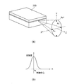
図1(a)は、一般的なレーザダイオード200から出射されたレーザ光を、その光軸と直交する投影面上に投影したときに当該投影面上に形成されるビームスポットSp1の形状を示す図である。図1(b)は、当該ビームスポットにおける輝度分布を示す図である。ビームスポットSp1は、レーザダイオード200のpn接合面に対して平行なX方向における幅AHが、pn接合面に対して垂直なY方向における幅AVよりも小さい楕円形形状を有している。ビームスポットSp1の光強度分布は、光軸中心における光強度が最も高く、光軸中心から外側に向けて光強度が緩やかに低下する対称型ガウシアン分布となる。
FIG. 1A shows the shape of a beam spot Sp1 formed on a projection surface when laser light emitted from a
車両用灯具に用いられるレーザ光源装置においては、このようなガウシアン分布の光強度分布を持つ光を集光レンズを介して蛍光体部に照射することにより白色光を生成する。この場合、白色光の光強度分布も同様にガウシアン分布となり、発光エリアの端部における光強度が相対的に低い。車両用灯具においては、レンズやリフレクタなどの光学系を用いて光源からの光を路面上に投影する。路面上の照度は光源からの距離の2乗に反比例するところ、路面の遠方側を照らす光源端部の輝度が相対的に低い場合には、路面遠方における照度が、車両近傍における照度よりも低くなり、いわゆるカットオフラインと称される明暗境界線が不明瞭となり遠方視認性が低下する。そこで、光源の前方にシェード等の遮光部材を設けて光源からの光を部分的に遮断することにより明暗境界線を明瞭にすることが行われている。しかしながら、この場合、光の利用効率が著しく低下する。レーザダイオードの中には面発光レーザのように図1のような楕円形ではないビームスポットを持つものもあるが、光軸中心の光強度が最も高く外側に向けて緩やかに低下する分布をもつことは同様のため、同様の問題を有する。 In a laser light source device used for a vehicular lamp, white light is generated by irradiating the phosphor portion with light having such a Gaussian distribution light intensity distribution via a condenser lens. In this case, the light intensity distribution of the white light is similarly a Gaussian distribution, and the light intensity at the end of the light emitting area is relatively low. In a vehicle lamp, light from a light source is projected on a road surface using an optical system such as a lens or a reflector. The illuminance on the road surface is inversely proportional to the square of the distance from the light source. When the luminance of the light source end that illuminates the far side of the road surface is relatively low, the illuminance at the far road surface is lower than the illuminance near the vehicle. Thus, the bright and dark boundary line called so-called cut-off line becomes unclear, and the distance visibility is lowered. Therefore, a light / dark boundary line is made clear by providing a light blocking member such as a shade in front of the light source to partially block light from the light source. However, in this case, the light use efficiency is significantly reduced. Some laser diodes, such as surface-emitting lasers, have a beam spot that is not elliptical as shown in FIG. 1, but have a distribution in which the light intensity at the center of the optical axis is the highest and gradually decreases outward. Because it is similar, it has similar problems.
本発明は、上記した点に鑑みてなされたものであり、車両用灯具に用いた場合などに光の利用効率を低下させることなく遠方視認性を改善することができるレーザ光源装置を提供することを目的とする。 The present invention has been made in view of the above points, and provides a laser light source device capable of improving far visibility without reducing light utilization efficiency when used in a vehicular lamp. With the goal.
本発明に係るレーザ光源装置は、レーザ出射口からレーザ光を発するレーザ光源と、前記レーザ光源のレーザ出射方向前方に設けられて、前記レーザ光を集光する集光レンズと、を含み、さらに、前記レーザ光源と前記集光レンズとの間に設けられて、前記レーザ出射口の外側に前記レーザ光の光軸に沿って延在する端面によって形成された反射面を有する導光部と、を有し、前記導光部の前記端面に対向する面は、反射防止面を有するかもしくは前記端面と反対側の領域に広がる半値角範囲内の光が反射されずそのまま前記集光レンズに到達するように光軸から離れて設けられ、前記レーザダイオードのpn接合面と平行な方向における半値全角θHと、前記レーザ光の光軸中心と前記反射面との間の距離W[mm]との関係が、W<0.064θH−0.032を満たすことを特徴としている。 A laser light source device according to the present invention includes a laser light source that emits laser light from a laser emission port, and a condensing lens that is provided in front of the laser light source in the laser emission direction and condenses the laser light. A light guide unit provided between the laser light source and the condenser lens, and having a reflection surface formed by an end surface extending along the optical axis of the laser light outside the laser emission port; The surface facing the end surface of the light guide portion has an antireflection surface or light within a half-value angle range extending in a region opposite to the end surface is not reflected and reaches the condenser lens as it is. And a full width at half maximum θ H in a direction parallel to the pn junction surface of the laser diode, and a distance W [mm] between the optical axis center of the laser beam and the reflecting surface, The relationship is W <0.0 It is characterized by satisfying 64θ H −0.032.
また、本発明に係る他のレーザ光源装置は、レーザ出射口からレーザ光を発するレーザ光源と、前記レーザ光源のレーザ出射方向前方に設けられて前記レーザ光を受光して前記レーザ光の波長とは異なる波長の光を発する波長変換部と、を含み、さらに、前記レーザ光源と前記波長変換部との間に設けられて、前記レーザ出射口の外側に前記レーザ光の光軸に沿って延在する端面によって形成された反射面を有する導光部と、を有し、前記導光部の前記端面に対向する面は、反射防止面を有するかもしくは前記端面と反対側の領域に広がる半値角範囲内の光が反射されずそのまま前記集光レンズに到達するように光軸から離れて設けられ、前記レーザダイオードのpn接合面と平行な方向における半値全角θHと、前記レーザ光の光軸中心と前記反射面との間の距離W[mm]との関係が、W<0.064θH−0.032を満たすことを特徴としている。 Further, another laser light source device according to the present invention includes a laser light source that emits laser light from a laser emission port, a laser light source that is provided in front of the laser light source in the laser emission direction, receives the laser light, and has a wavelength of the laser light. Includes a wavelength conversion unit that emits light of different wavelengths, and is further provided between the laser light source and the wavelength conversion unit, and extends along the optical axis of the laser light outside the laser emission port. A light guide portion having a reflection surface formed by an existing end surface, and a surface opposite to the end surface of the light guide portion has an antireflection surface or spreads in a region opposite to the end surface The half-width full angle θ H in a direction parallel to the pn junction surface of the laser diode is provided so that light within the angular range is not reflected and reaches the condenser lens as it is, and the light of the laser light Axis center and front The relationship with the distance W [mm] between the reflecting surfaces satisfies W <0.064θ H −0.032.
本発明に係るレーザ光源装置によれば、導光部内を伝搬するレーザ光は、光軸と平行な導光部の端面で全反射により反射される。導光部の端面で折り返された光は、蛍光体部の受光面上に形成されるビームスポット上に重ねられる。これにより、蛍光体部の発光エリアにおいて導光部の端面に対応して形成される発光エリア端部の輝度を高めることができる。 According to the laser light source device of the present invention, the laser light propagating in the light guide is reflected by total reflection at the end face of the light guide parallel to the optical axis. The light that is folded back at the end face of the light guide unit is superimposed on a beam spot formed on the light receiving surface of the phosphor unit. Thereby, the brightness | luminance of the light emission area edge part formed corresponding to the end surface of a light guide part in the light emission area of a fluorescent substance part can be raised.
以下、本発明の実施例について図面を参照しつつ説明する。尚、以下に示す図において、実質的に同一又は等価な構成要素、部分には同一の参照符を付している。 Embodiments of the present invention will be described below with reference to the drawings. In the drawings shown below, substantially the same or equivalent components and parts are denoted by the same reference numerals.
(実施例1)
図2は、本発明の実施例1に係るレーザ光源装置1の斜視図である。図3(a)は、レーザ光源装置1の主要部分の断面図である。図3(b)は、半導体レーザ10を構成するレーザダイオード12の斜視図である。
Example 1
FIG. 2 is a perspective view of the laser
半導体レーザ10は、光源となるレーザ光を生成するデバイスである。半導体レーザ10は、ヒートシンク11、ヒートシンク11上に搭載されたレーザダイオード12、ヒートシンク11に接続されたリード13などにより構成される。レーザダイオード12は、例えばGaN等の窒化物半導体層を含み、波長450nm前後の青色レーザ光をレーザ出射端面のレーザ出射口12aから出射する。尚、レーザ出射口12aの幅は、例えば100μm程度である。
The
集光レンズ20は、半導体レーザ10のレーザ出射方向前方に設けられ、レーザ光を受光する。集光レンズ20は、半導体レーザ10から出射されたレーザ光を集光してレーザ蛍光体部40の受光面にビームスポットを形成する。
The
導光部30は、半導体レーザ10から集光レンズ20に至るレーザ光の光路を形成する光透過性部材である。すなわち、導光部30は半導体レーザ10と集光レンズ20との間の空間を充たしており、半導体レーザ10から出射された光は導光部30内に入射して、導光部30内を伝搬して集光レンズ20に至る。導光部30は、外部空間を充たす空気よりも高い屈折率を有する材料、例えばガラスまたは樹脂などにより構成することができる。半導体レーザ10および集光レンズ20は、図2および図3(a)に示すように、その一部が導光部30に埋め込まれていてもよい。
The
導光部30は、レーザ出射口12aよりも外側であり且つレーザ光の光軸と平行な端面31を有する。すなわち、導光部の端面31は、レーザ光の光軸に沿って延在している。導光部の端面31は、光軸中心AXの近傍に配置することが好ましく、例えば光軸中心AXからの距離Wが150μmとなる位置に配置される。光軸中心AXと導光部の端面31との間の距離Wがゼロとなった場合には、レーザ出射口12aから出射される光の約半分が導光部30の外側に漏出することになる。このような光の漏出が生じることなくレーザ出射口12aから出射された全ての光を導光部30内に取り込めるように、導光部30は、レーザ出射口12aと完全にオーバラップしている。すなわち、導光部の端面31は、レーザ出射口12aの外側に位置している。また、導光部の端面31は、レーザダイオード12のpn接合面と直交していることが好ましい。導光部30は、図2に示すように四面体形状を有していてもよい。光軸を挟んで端面31と反対側の領域において広がるレーザ光は、反射を介して集光レンズ20に到達することは望ましくない。そこで、反射光を生じさせないようにするため、導光部30の端面31に対向する面は、光吸収膜を設けるなどの反射防止加工を施すか、端面31と反対側の領域に広がる半値角範囲内の光がそのまま集光レンズ20に到達するように、例えば光軸から5mm以上離すようにすることが好ましい。よって、集光レンズ20は、端面31側に広がる半値角範囲内の光が端面31から一回反射により到達し且つ端面31と反対側に広がる半値角範囲内の光が反射されずそのまま集光レンズ20に到達するような位置、サイズで設けられるのが好ましい。集光レンズ20は、導光部の端面31の位置まで延在しており、導光部の端面31近傍に到来する光を取り込めるようになっている。
The
蛍光体部(波長変換部)40は、集光レンズ20のレーザ出射方向前方側の焦点の近傍に設けられ、集光レンズ20によって集光されたレーザ光をその受光面において受光する。蛍光体部40は、例えば、シリコーン樹脂等の光透過性樹脂からなるバインダにYAG:Ce蛍光体を分散させて構成される。蛍光体部40は、半導体レーザ10から出射される波長450nm前後の青色光を吸収して、これを例えば波長560nm前後に発光ピークを持つ黄色光に変換して出力する。蛍光体部40により波長変換された黄色光と、波長変換されずに蛍光体部40を透過した青色光が混ざることにより、蛍光体部40の光放出面からは白色光が放出される。尚、蛍光体部40は、波長変換に伴って生じる熱を拡散するための放熱板に接合されていてもよい。
The phosphor part (wavelength conversion part) 40 is provided in the vicinity of the focal point on the front side in the laser emission direction of the
図4(a)は、本発明の実施例に係る導光部30内を伝搬するレーザ光の進路、蛍光体部40の受光面に形成されるビームスポット(発光エリア)Spの形状およびビームスポットSpにおける光強度分布を並べて表示したものである。図4(b)は導光部の端面31aが、光軸中心AXから十分離れたところに位置している比較例に係る構成の導光部30aを用いた場合における蛍光体部40の受光面に形成されるビームスポット(発光エリア)Sp1の形状およびビームスポットSp1における光強度分布を並べて表示したものである。図4(b)において、端面31aはレーザ光が反射することなく集光レンズ20に到達するような位置にある。この場合、ビームスポットSp1および光強度分布は、図1に示した従来のものと同一となりビームスポットSp1の形状は楕円形であり、光強度の変化はなだらかである。一方、図4(a)を参照すると、半導体レーザ10から出射されたレーザ光は、光軸中心AXを中心として広がりながら導光部30内を伝搬する。導光部30は、外部空間を充たす空気よりも屈折率の高い材料で構成されているので、導光部の端面31に臨界角以上の角度で入射するレーザ光は、導光部の端面31で全反射により反射される。尚、導光部30を構成する光透過性部材の屈折率を1.45、空気の屈折率を1.0とした場合、臨界角は41.8°となる。導光部の端面31は、光軸中心AXと平行であり且つ光軸中心AXの近傍に配置されるので、導光部の端面31に直接入射するほぼ全ての光線は端面31で全反射によって反射される。従って、導光部の端面31から外部に放射される光は殆どない。
FIG. 4A shows the path of laser light propagating through the
蛍光体部40の受光面には、半導体レーザ10からの直接光線と、導光部の端面31で反射された反射光線とが重なってビームスポット(発光エリア)Spが形成される。このように、導光部の端面31での光を折り返すことにより形成されるビームスポット(発光エリア)Spの形状は、楕円形の一部を導光部の端面31に対応するラインで切り欠いた形状となる。より具体的には、導光部の端面31を光軸と平行且つレーザダイオード12のpn接合面に対して垂直に配置したことにより、ビームスポットSpの形状は、楕円形をその長軸と平行なラインでカットしたような細長い形状となる。以下において、この導光部の端面31によってもたらされるビームスポット(発光エリア)Spのカットラインを折り返しラインTLと称することとする。このように、ビームスポットSpは、直接光線と反射光線との重ね合わせにより形成されるので、ビームスポット(発光エリア)Sp内における光強度が増加する。特に、ビームスポット(発光エリア)Spの端部すなわち折り返しラインTL近傍における光強度の増加が顕著となる。例えば、半値全角θHが16°のレーザ光を使用する場合、導光部の端面31を光軸中心AXからの距離Wが150μm程度となる位置に配置することにより、半導体レーザ10から出射されるレーザ光の約半分が、導光部の端面31で折り返され、ビームスポットSpの折り返しラインTL上(すなわち発光エリア端部)に光強度のピークを形成することができ、しかもピーク強度を通常の約2倍にまで高めることができる。蛍光体部40は、その受光面に形成されるビームスポットSpの光強度分布に応じた光強度分布を有する白色光を光放出面から放出する。このように、本実施例に係るレーザ光源装置1によれば、発光エリア端部である折り返しラインTLに向かって急峻に光強度が増大する輝度勾配を持つ光を生成することが可能となる。
On the light receiving surface of the
図5は、上記した本発明の実施例に係るレーザ光源装置1を光源として備えた所謂ダイレクトプロジェクション型の車両用灯具100の構成を示す図である。レーザ光源装置1は、導光部の端面31が、鉛直方向下方を向くように配置される。非球面レンズ101は、レーザ光源装置1の投光方向前方に配置されている。レーザ光源装置1の蛍光体部40から放射される白色光は、非球面レンズ101に直接照射される。非球面レンズ101は、レーザ光源装置1から放射された光の像を上下反転させて投光方向前方に拡大投影する。
FIG. 5 is a diagram showing a configuration of a so-called direct projection type
図6は、車両用灯具100からの光を投光方向前方に設置されたスクリーンSc上に照射したときのスクリーンSc上に形成される配光パターンPを示す図である。尚、図6において、Hは水平線、Vは鉛直線であり、破線は投光方向前方に向けて伸びる仮想路面である。対向車線側のカットオフラインが自車線側のカットオフラインよりも鉛直方向下方に位置することによりすれ違いビームに適した配光パターンPが形成される。車両用灯具100を構成する非球面レンズ101は、図4(a)に示すビームスポットSpの折り返しラインTLに対応する像部分TL´が、カットオフラインCLに沿うようにスクリーン上に複数の投影像q1を形成する。本実施例に係るレーザ光源装置1によれば、ビームスポット(発光エリア)Spにおいて、光強度のピークは折り返しラインTL上に存在するので、カットオフラインCLの近傍に照度ピークが形成される。すなわち、カットオフラインCLの近傍が最も明るく、鉛直方向下方に向けて照度が低下する配光パターンPが形成される。更に、ビームスポット(発光エリア)Spの折り返しラインTLでは、光の折り返しの効果により従来のピーク強度の約2倍の光強度が得られる故、カットオフラインCL近傍の照度を従来よりも高めることができる。その結果、シェード等の遮光部材を用いない場合であってもカットオフラインCLを挟んだ明部と暗部の明暗差がより明瞭な配光パターンPが形成される。
FIG. 6 is a diagram showing a light distribution pattern P formed on the screen Sc when the light from the
図7(a)は、車両用灯具100を車両に設置して路面を照射した場合の路面上における等照度曲線である。比較例として示される図7(b)は、ガウシアン分布となる光強度分布を有する光を集光レンズを介して蛍光体に照射して白色光を得る従来の光源装置を用いた車両用灯具を備えた車両における等照度曲線である。本実施例に係るレーザ光源装置を備えた車両用灯具100によれば、上記したように、カットオフラインCL近傍の照度を従来よりも高めることができるので、従来よりも等照度曲線を遠方側に延ばすことができ、遠方視認性が大幅に改善される。路面上の照度は光源からの距離の2乗に反比例するところ、発光エリア端部である折り返しラインTL上に光強度ピークを持つ光源を使用することにより、遠方における照度低下を補う効果が得られる。つまり、レーザ光源装置1は、折り返しラインTLに向かって光強度が急峻に高くなる輝度分布を有する光源を構成しているので、車両近傍から遠方に亘る路面上を略均一な照度で照らすことが可能となり、夜間走行の安全性を向上することができる。
FIG. 7A is an isoilluminance curve on the road surface when the
本発明の実施例に係るレーザ光源装置1において、導光部の端面31の配置について以下に説明する。
In the laser
導光部30の端面31は、半導体レーザ10から出射されるレーザ光の光軸と平行であり且つレーザダイオード12のpn接合面と垂直となるように配置される。一般的に、ビームスポット形状は図1に示すように楕円形を有しているので、pn接合面に対して垂直な向きに導光部の端面31を配置することにより、端面31でレーザ光を折り返した場合に細長い形状のビームスポットを形成することができる。すなわち、従来のフィラメントを用いた光源と同様の細長い発光形状を得ることができる。これにより、レーザ光源装置1を車両用灯具に用いる場合に、配光設計が容易となり、フィラメント光源に適合するように構成されたリフレクタやレンズ等の光学系部材をそのまま転用することも可能となる。ただし、本発明において半導体レーザ10は楕円形のビームスポットを持つものに限定されず、面発光レーザなどの円形のビームスポットを持つものを用いても構わない。この場合においても光強度が急峻に高くなる輝度分布を有する光源となることは同様である。
The
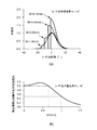
図8(a)は、光軸中心AXと導光部の端面31との間の距離Wを変化させたときの、蛍光体部40の受光面に形成されるビームスポットの光強度分布を示したものである。図8(a)において横軸は、レーザダイオードのpn接合面と平行な角度における導光部の端面での反射後の光の広がりである。すなわち、出射角度0°は光軸中心の位置である。一方、図8(a)において縦軸は、蛍光体部40の受光面における光強度である。破線で示す曲線は、導光部の端面31において全反射が生じないとした場合(すなわち、端面31が存在しない場合)の光強度分布である。尚、図8(a)に示される各強度分布曲線は、レーザダイオードのpn接合面と平行な方向の半値全角θHが16°のレーザ光を使用した場合のものである。レーザ光は、導光部の端面31で全反射により反射される故、端面31の外側には光は放出されない。従って、導光部の端面31の存在する角度位置がビームスポット(発光エリア)の端部となる。光軸中心AXと導光部の端面31との間の距離Wが小さくなる程、すなわち、導光部の端面31が光軸中心AXに近づく程、ビームスポット(発光エリア)の端部における光強度が高くなる。例えば、距離Wを0.44mmに設定した場合、ビームスポット(発光エリア)の端部に光強度のピークを形成することができ、距離Wを0.15mmに設定した場合、光強度のピークを、端面31が存在しない場合の約2倍にまで高めることができる。
FIG. 8A shows the light intensity distribution of the beam spot formed on the light receiving surface of the
図8(b)は、ビームスポット(発光エリア)の端部における光強度Ieと光軸中心位置(出射角度0°)における光強度Icとの比Ie/Icと、光軸中心AXと導光部の端面31との間の距離Wと、の関係を示す図である。尚、図8(b)に示される曲線は、レーザダイオードのpn接合面と平行な方向の半値全角θHが16°のレーザ光を使用した場合のものである。距離Wを0.7mm以下に設定することによりビームスポット(発光エリア)の端部に光強度のピークを形成することができる。一方、距離Wを0.7mmよりも大きく設定する場合、ビームスポット(発光エリア)の端部における光強度は距離Wの増加に伴って低下する。すなわち、距離Wの大きさが過大となると、路面遠方を照らす部分の光強度が低下するので、レーザ光源装置1を車両用灯具に適用した場合に、上記の遠方視認性改善の効果が減退する。車両用灯具における遠方視認性の改善効果を確保するために、ビームスポット(発光エリア)の端部における光強度Ieと、光軸中心位置における光強度Icの比Ie/Icは0.5以上であることが好ましい。従って、図8(b)に示される曲線から光軸中心AXと導光部の端面31との間の距離Wを0.99mm以下に設定することが好ましい。尚、Ie/Icが0.5より大きく1.0より小さい範囲では折り返しラインTLと光強度のピークの位置は異なるが、この場合、折り返しラインTLで形成される光像をカットオフラインCLに合わせる。Ie/Icが上記範囲にある場合でも光強度のピークは折り返しラインTLの近傍に位置するため本発明の効果は得られる。
FIG. 8B shows the ratio Ie / Ic between the light intensity Ie at the end of the beam spot (light emitting area) and the light intensity Ic at the optical axis center position (
レーザ光の半値全角θHが16°以外の場合についても同様の分析を行った。図9は、レーザ光の半値全角θHが8°、12°、16°、20°、24°の場合におけるIe/Ic=0.5となる点をプロットしたものである。図9において横軸はレーザダイオードのpn接合面と平行な方向の半値全角θHであり、縦軸は光軸中心AXと導光部の端面31との間の距離Wである。図9における各プロットは、車両用灯具における遠方視認性の改善効果を確保するために必要とされる距離Wの最大値である。かかる距離Wの最大値Wmaxとレーザ光の半値全角θHとの間には正比例の関係で近似することができる。すなわち、図9に示される各プロット間を結ぶ直線はWmax=0.064θH−0.032で表わすことができる。従って、距離Wの好ましい設定範囲は、W<0.064θH−0.032[mm]であり、図9においてハッチングで示される領域となる。図9より、例えば半値全角θHが16°のレーザ光を使用する場合、光軸中心AXとの間の距離が1mm以下となる位置に導光部の端面31を配置すればよいことが理解できる。
The same analysis was performed when the full width at half maximum θ H of the laser beam was other than 16 °. FIG. 9 is a plot of points where Ie / Ic = 0.5 when the full width at half maximum θ H of the laser beam is 8 °, 12 °, 16 °, 20 °, and 24 °. In FIG. 9, the horizontal axis is the full width at half maximum θ H in the direction parallel to the pn junction surface of the laser diode, and the vertical axis is the distance W between the optical axis center AX and the
以上の説明から明らかなように、本発明の実施例に係るレーザ光源装置1において、レーザ光の光路を形成する導光部30は、レーザダイオード12のレーザ出射口12aの外側にレーザ光の光軸と平行な端面31を有する。導光部の端面31は導光部内を伝搬するレーザ光を全反射により反射させる反射面を形成しているので、端面31でレーザ光が折り返され、元々の分布とは異なる光強度分布を持つビームスポットを形成することができる。より具体的には、ビームスポット(発光エリア)の端部である折り返しラインTL近傍における光強度を高めることができる。更に、導光部の端面31を光軸中心AXにより近づけることにより折り返しラインTL上に光強度のピークを形成することができる。このような光強度分布を持つレーザ光源装置1を車両用灯具の光源として使用する場合において、発光エリア端部となる折り返しラインTLがカットオフラインCLに沿うように投影像を形成する光学系を構築することにより、車両の近傍と遠方の照度が均一な配光を得ることが可能となり、遠方視認性を改善することが可能となる。また、シェード等の遮光部材を用いない場合であっても明暗境界線を挟む明部と暗部の明暗差を明瞭とすることができる。
As is clear from the above description, in the laser
(実施例2)
図10(a)および図10(b)は、それぞれ、本発明の実施例2に係るレーザ光源装置2の構成を示す斜視図および断面図である。レーザ光源装置2において、蛍光体部40は、上記した実施例1に係るレーザ光源装置1の集光レンズ20の形成位置に設けられている。すなわち、蛍光体部40は、半導体レーザ10のレーザ出射方向前方に設けられ、半導体レーザ10から出射されたレーザ光は、集光レンズを介さずに蛍光体部40の受光面に直接照射される。
(Example 2)
FIG. 10A and FIG. 10B are a perspective view and a cross-sectional view, respectively, showing the configuration of the laser
導光部30は、半導体レーザ10から蛍光体部40に至るレーザ光の光路を形成している。すなわち、導光部30は半導体レーザ10と蛍光体部40との間の空間を充たしており、半導体レーザ10から出射された光は導光部30内に入射して、導光部30内を伝搬して蛍光体部40に至る。半導体レーザ10および蛍光体部40は、その一部が導光部30に埋め込まれていてもよい。半導体レーザ10と蛍光体部40との距離が過大となると、蛍光体部の受光面に形成されるビームスポットのサイズが大きくなり、配光設計が困難となる場合がある。従って、半導体レーザ10と蛍光体部40との間の距離は、半導体レーザ10から出射されるレーザ光の半値全角に応じて設定するのが好ましい。例えば、レーザダイオード12のpn接合面と平行な方向における半値全角θHが16°である場合、半導体レーザ10と蛍光体部40との距離を約5mmに設定することが好ましい。蛍光体部40は、導光部の端面31の位置まで延在しており、導光部の端面31近傍に到来する光を取り込めるようになっている。光軸を挟んで端面31と反対側の領域において広がるレーザ光は、反射を介して蛍光体部40に到達することは望ましくない。そこで、反射光を生じさせないようにするため、導光部30の端面31に対向する面は、光吸収膜を設けるなどの反射防止加工を施すか、端面31と反対側の領域に広がる半値角範囲内の光がそのまま蛍光体部40に到達するように、例えば光軸から5mm以上離すようにすることが好ましい。よって、蛍光体部40は、端面31側に広がる半値角範囲内の光が端面31から一回反射により到達し且つ端面31と反対側に広がる半値角範囲内の光が反射されずそのまま蛍光体部40に到達するような位置、サイズで設けられるのが好ましい。導光部の端面31の配置に関しては上記した実施例1に係るレーザ光源装置1と同様であるので、その説明は省略する。
The
このように、本実施例に係るレーザ光源装置2は、半導体レーザ10から出射されるレーザ光を集光レンズを介さずに直接蛍光体部40に照射して、蛍光体部20から白色光を取り出すように構成されている。かかる構成によれば、レーザ出射方向と交差する方向(すなわち横方向)に広がった拡散光を生成することが可能となる。上記した実施例1に係るレーザ光源装置1は、路面の遠方を照らす前照灯用の光源として好適であるのに対して本実施例に係るレーザ光源装置2は、路面の左右方向を広く照らすフォグランプ用の光源として好適である。また本実施例に係るレーザ光源装置によれば、実施例1の場合と同様、車両近傍から遠方に亘り略均一な明るさで路面を照らすことが可能となる。ランプ取り付け要件により、フォグランプはヘッドランプに比べて車両取り付け高さ位置が低い。このためにガウシアン分布の光強度分布を持つ従来の光源では遠方に照射する光強度が弱くなり、多くの光が路面手前へ分配されてしまう。本発明に係る光源装置によれば、フォグランプに適用する場合においても遠方を見やすくする効果をもたらし有効である。
As described above, the laser
図11は、集光レンズを有さない本発明の実施例2に係るレーザ光源装置2を備えたリフレクタ型の車両用灯具110の構成を示す図である。レーザ光源装置2は、導光部の端面31が投光方向後方を向き且つ蛍光体部40の光放出面がリフレクタ112の光反射面と対向するように配置される。光学系を形成するリフレクタ112は、回転放物面を形成する光反射面を有し、その焦点位置が蛍光体部40の近傍に設定されている。リフレクタ112の反射面は、複数の単位反射面からなるいわゆるマルチリフレクタ構造を有している。リフレクタ112は、光反射面が蛍光体部40の光放出面と対向するようにレーザ光源装置1の下方側に配置され、蛍光体部40から放出される光を投光方向前方に向けて反射させる。
FIG. 11 is a diagram illustrating a configuration of a reflector-
(実施例3)
図12は、本発明の実施例3に係るレーザ光源装置3の構成を示す断面図である。レーザ光源装置3は、導光部の端面31を覆う反射膜50を更に有する点が上記した実施例2に係るレーザ光源装置2と異なる。反射膜50は、反射率の高いAgやAlなどの金属により構成することができる。反射膜50以外の構成部分は、実施例2に係るレーザ光源装置2と同様であるので、それらの説明については省略する。
(Example 3)
FIG. 12 is a cross-sectional view showing a configuration of a laser
導光部30内を伝搬するレーザ光のうち臨界角以上の角度で端面31に入射するものは、導光部30と空気との屈折率差によって端面31で全反射により反射されることとなるが、臨界角よりも小さい角度で端面31に入射するものは端面31を透過して外部に放射される。例えば、蛍光体部40が樹脂からなるバインダを含む場合、その受光面において反射された光は、臨界角よりも小さい角度で導光部の端面31に入射して外部に放出される可能性が高い。導光部の端面31を反射膜50で覆うことにより、そのような透過光を再び導光部30内に戻すことが可能となり、光の利用効率が向上するとともに、アイセーフ機能も改善される。
Of the laser light propagating in the
尚、上記の説明においては、実施例2に係る半導体発光装置2をベースとした構成を例示したが、集光レンズを有する実施例1に係る発光装置1において、導光部の端面31を反射膜で覆うこととしてもよい。また、導光部30を設けることなく端面31の存在していた位置に反射面のみを設けることとしてもよい。これにより、図4(a)に示されているような光強度分布を得ることができる。また、光軸を挟んで反射面と反対側の光軸から5mm以内の領域は反射面などが設けられていない空間があるのみとなる。ただし、導光部30を用いずにレーザ出射口12の近傍に反射面を設けることは製造上困難であるため、導光部30に反射膜を設けた方が製造上優位である。
In the above description, the configuration based on the semiconductor
(実施例4)
図13(a)および図13(b)は、それぞれ、本発明の実施例4に係るレーザ光源装置4の構成を示す斜視図および断面図である。レーザ光源装置4は、導光部30の外側全体を覆う遮光部60を更に有する点が上記した実施例2に係るレーザ光源装置2と異なる。遮光部60は、遮光性を有する材料、例えば金属、樹脂などにより構成され、導光部30を透過したレーザ光の外部への放出を遮断する。遮光部60は、蛍光体部40の形成位置に開口部61を有しており、蛍光体部40から放出される白色光は、開口部61から取り出せるようになっている。開口部61は、蛍光体部40と同一またはそれよりも小さいサイズで形成される。このように、導光部30の外側全体を遮光部60で囲うことにより、導光部30内で生じる迷光に起因するグレアの発生防止することができる。
Example 4
FIGS. 13A and 13B are a perspective view and a cross-sectional view, respectively, showing the configuration of the laser
尚、上記の説明においては、実施例2に係る半導体発光装置2をベースとした構成を例示したが、集光レンズを有する実施例1に係る発光装置1において、導光部30の外側を遮光部で覆うこととしてもよい。尚、上記した各実施例に係る構成は適宜組み合わせることが可能である。
In the above description, the configuration based on the semiconductor
1、2、3、4 レーザ光源装置
10 半導体レーザ
12 レーザダイオード
12a レーザ出射口
20 集光レンズ
30 導光部
31 端面
40 蛍光体部
50 反射膜
60 遮光部
100 車両用灯具
1, 2, 3, 4 Laser
Claims (8)
前記レーザ光源のレーザ出射方向前方に設けられて、前記レーザ光を集光する集光レンズと、を含み、
さらに、前記レーザ光源と前記集光レンズとの間に設けられて、前記レーザ出射口の外側に前記レーザ光の光軸に沿って延在する端面によって形成された反射面を有する導光部と、を有し、
前記導光部の前記端面に対向する面は、反射防止面を有するかもしくは前記端面と反対側の領域に広がる半値角範囲内の光が反射されずそのまま前記集光レンズに到達するように光軸から離れて設けられ、
前記レーザダイオードのpn接合面と平行な方向における半値全角θHと、前記レーザ光の光軸中心と前記反射面との間の距離W[mm]との関係が、W<0.064θH−0.032を満たすことを特徴とするレーザ光源装置。 A laser light source that emits laser light from a laser emission port;
A condenser lens provided in front of the laser light source in the laser emission direction and condensing the laser light,
A light guide unit provided between the laser light source and the condensing lens and having a reflection surface formed by an end surface extending along the optical axis of the laser light outside the laser emission port; Have
The surface of the light guide portion facing the end surface has an antireflection surface or light so that light within a half-value angle range extending in a region opposite to the end surface is not reflected and reaches the condenser lens as it is. Provided away from the shaft,
The relation between the full width at half maximum θ H in the direction parallel to the pn junction surface of the laser diode and the distance W [mm] between the optical axis center of the laser beam and the reflecting surface is W <0.064θ H − A laser light source device satisfying 0.032.
前記レーザ光源のレーザ出射方向前方に設けられて前記レーザ光を受光して前記レーザ光の波長とは異なる波長の光を発する波長変換部と、を含み、
さらに、前記レーザ光源と前記波長変換部との間に設けられて、前記レーザ出射口の外側に前記レーザ光の光軸に沿って延在する端面によって形成された反射面を有する導光部と、を有し、
前記導光部の前記端面に対向する面は、反射防止面を有するかもしくは前記端面と反対側の領域に広がる半値角範囲内の光が反射されずそのまま前記波長変換部に到達するように光軸から離れて設けられ、
前記レーザダイオードのpn接合面と平行な方向における半値全角θHと、前記レーザ光の光軸中心と前記反射面との間の距離W[mm]との関係が、W<0.064θH−0.032を満たすことを特徴とするレーザ光源装置。 A laser light source that emits laser light from a laser emission port;
A wavelength conversion unit that is provided in front of a laser emission direction of the laser light source and that receives the laser light and emits light having a wavelength different from the wavelength of the laser light,
A light guide unit provided between the laser light source and the wavelength conversion unit, and having a reflection surface formed by an end surface extending along an optical axis of the laser beam outside the laser emission port; Have
The surface of the light guide portion facing the end surface has an antireflection surface or light so that light within a half-value angle range extending in a region opposite to the end surface is not reflected and reaches the wavelength conversion portion as it is. Provided away from the shaft,
The relation between the full width at half maximum θ H in the direction parallel to the pn junction surface of the laser diode and the distance W [mm] between the optical axis center of the laser beam and the reflecting surface is W <0.064θ H − A laser light source device satisfying 0.032.
Priority Applications (3)
| Application Number | Priority Date | Filing Date | Title |
|---|---|---|---|
| JP2011254936A JP5883623B2 (en) | 2011-11-22 | 2011-11-22 | Laser light source device |
| US13/680,424 US9182103B2 (en) | 2011-11-22 | 2012-11-19 | Laser light source device |
| EP12007821.7A EP2597735B1 (en) | 2011-11-22 | 2012-11-20 | Laser light source device |
Applications Claiming Priority (1)
| Application Number | Priority Date | Filing Date | Title |
|---|---|---|---|
| JP2011254936A JP5883623B2 (en) | 2011-11-22 | 2011-11-22 | Laser light source device |
Publications (2)
| Publication Number | Publication Date |
|---|---|
| JP2013110005A JP2013110005A (en) | 2013-06-06 |
| JP5883623B2 true JP5883623B2 (en) | 2016-03-15 |
Family
ID=47713749
Family Applications (1)
| Application Number | Title | Priority Date | Filing Date |
|---|---|---|---|
| JP2011254936A Active JP5883623B2 (en) | 2011-11-22 | 2011-11-22 | Laser light source device |
Country Status (3)
| Country | Link |
|---|---|
| US (1) | US9182103B2 (en) |
| EP (1) | EP2597735B1 (en) |
| JP (1) | JP5883623B2 (en) |
Families Citing this family (13)
| Publication number | Priority date | Publication date | Assignee | Title |
|---|---|---|---|---|
| JP2014022472A (en) * | 2012-07-13 | 2014-02-03 | Sharp Corp | Light emission device, lighting device, and light emission method |
| JP2014019860A (en) * | 2012-07-24 | 2014-02-03 | Shin Etsu Chem Co Ltd | Manufacturing method of phosphor precursor, manufacturing method of phosphor, and wavelength conversion parts |
| WO2015040671A1 (en) * | 2013-09-17 | 2015-03-26 | 三菱電機株式会社 | Vehicle-mounted headlight |
| KR101504251B1 (en) * | 2013-11-21 | 2015-03-19 | 현대모비스 주식회사 | Laser Optic Module |
| JP6201708B2 (en) * | 2013-12-11 | 2017-09-27 | スタンレー電気株式会社 | Vehicle lamp and lens body |
| KR101592649B1 (en) | 2013-12-24 | 2016-02-12 | 현대자동차주식회사 | Laser optical system for head lamp |
| WO2016065650A1 (en) * | 2014-11-01 | 2016-05-06 | 广州博冠光电技术有限公司 | Method for assembling manually-adjusted high-precision lens apparatus |
| AT517409B1 (en) * | 2015-06-30 | 2017-06-15 | Zkw Group Gmbh | Lighting module for a vehicle headlight and vehicle headlights |
| JP6719261B2 (en) * | 2016-04-15 | 2020-07-08 | シャープ株式会社 | Lighting device and vehicle headlight |
| CN108613045A (en) * | 2016-12-21 | 2018-10-02 | 常州星宇车灯股份有限公司 | A kind of overlength car atmosphere lamp using laser light source |
| US11231569B2 (en) * | 2018-06-13 | 2022-01-25 | Panasonic Corporation | Light-emitting device and illumination device |
| WO2021025136A1 (en) * | 2019-08-08 | 2021-02-11 | 株式会社小糸製作所 | Vehicle lamp |
| CN111884048B (en) * | 2020-07-31 | 2021-11-30 | 常州纵慧芯光半导体科技有限公司 | Laser device and manufacturing method and application thereof |
Family Cites Families (11)
| Publication number | Priority date | Publication date | Assignee | Title |
|---|---|---|---|---|
| US5758950A (en) * | 1996-03-05 | 1998-06-02 | Ricoh Company, Ltd. | Light source device for an image forming apparatus |
| JPH10153742A (en) * | 1996-11-21 | 1998-06-09 | Canon Inc | Multi-beam light source device |
| US6795243B1 (en) * | 2001-10-05 | 2004-09-21 | Optical Coating Laboratory, Inc. | Polarizing light pipe |
| JP4339156B2 (en) | 2004-03-18 | 2009-10-07 | 株式会社小糸製作所 | Vehicle lamp unit |
| JP4812543B2 (en) | 2006-06-28 | 2011-11-09 | 株式会社小糸製作所 | Vehicle lighting |
| US8636366B2 (en) * | 2008-03-28 | 2014-01-28 | Nec Display Solutions, Ltd. | Lighting apparatus including a light source, a first mirror, and a second mirror disposed between the light source and the first mirror |
| JP5257665B2 (en) | 2008-08-20 | 2013-08-07 | スタンレー電気株式会社 | Vehicle headlight unit and vehicle headlight |
| US8098347B2 (en) * | 2008-11-21 | 2012-01-17 | 3M Innovative Properties Company | Stereoscopic 3D liquid crystal display with graded light guide light extraction features |
| JP2010160948A (en) * | 2009-01-07 | 2010-07-22 | Olympus Corp | Light source device |
| JP5356998B2 (en) * | 2009-12-17 | 2013-12-04 | シャープ株式会社 | Vehicle headlamp |
| JP2011243369A (en) * | 2010-05-17 | 2011-12-01 | Sharp Corp | Light-emitting device, illumination device, and vehicle headlight |
-
2011
- 2011-11-22 JP JP2011254936A patent/JP5883623B2/en active Active
-
2012
- 2012-11-19 US US13/680,424 patent/US9182103B2/en active Active
- 2012-11-20 EP EP12007821.7A patent/EP2597735B1/en active Active
Also Published As
| Publication number | Publication date |
|---|---|
| EP2597735A2 (en) | 2013-05-29 |
| EP2597735B1 (en) | 2019-06-19 |
| US20130128584A1 (en) | 2013-05-23 |
| EP2597735A3 (en) | 2017-09-20 |
| JP2013110005A (en) | 2013-06-06 |
| US9182103B2 (en) | 2015-11-10 |
Similar Documents
| Publication | Publication Date | Title |
|---|---|---|
| JP5883623B2 (en) | Laser light source device | |
| JP5445923B2 (en) | Vehicle lighting | |
| JP5722702B2 (en) | Vehicle lighting | |
| JP5829478B2 (en) | Vehicle lighting | |
| US9103517B2 (en) | Vehicle light | |
| JP6164518B2 (en) | Vehicle headlamp | |
| JP5657357B2 (en) | Vehicle lighting | |
| US8152346B2 (en) | Vehicle lighting unit and vehicle light | |
| JP5521259B2 (en) | Vehicle lighting | |
| US20140112012A1 (en) | Vehicle headlamp | |
| CN108027118B (en) | Light source device and light projector | |
| WO2014109187A1 (en) | Vehicle lamp | |
| CN102192459A (en) | Vehicle headlamp and light emitting module for the vehicle headlamp | |
| JP5445049B2 (en) | Vehicle lighting | |
| JP5352686B2 (en) | Light projecting device, light projecting unit and light collecting member | |
| US10072812B2 (en) | Lens body and vehicle lighting fixture | |
| CN111373195B (en) | Lighting device for a motor vehicle | |
| JP6719261B2 (en) | Lighting device and vehicle headlight | |
| JP5891858B2 (en) | Light emitting device and vehicle lamp | |
| JP5446757B2 (en) | Vehicle lighting | |
| JP6052599B2 (en) | Vehicle headlamp | |
| JP2010123473A (en) | Vehicular lamp tool unit | |
| JP6072447B2 (en) | Lighting device and vehicle headlamp | |
| JP5397174B2 (en) | Vehicle lighting | |
| JP6760774B2 (en) | Vehicle lighting |
Legal Events
| Date | Code | Title | Description |
|---|---|---|---|
| A621 | Written request for application examination |
Free format text: JAPANESE INTERMEDIATE CODE: A621 Effective date: 20141111 |
|
| A977 | Report on retrieval |
Free format text: JAPANESE INTERMEDIATE CODE: A971007 Effective date: 20150715 |
|
| A131 | Notification of reasons for refusal |
Free format text: JAPANESE INTERMEDIATE CODE: A131 Effective date: 20150728 |
|
| A521 | Request for written amendment filed |
Free format text: JAPANESE INTERMEDIATE CODE: A523 Effective date: 20150924 |
|
| A131 | Notification of reasons for refusal |
Free format text: JAPANESE INTERMEDIATE CODE: A131 Effective date: 20151117 |
|
| A521 | Request for written amendment filed |
Free format text: JAPANESE INTERMEDIATE CODE: A523 Effective date: 20151221 |
|
| TRDD | Decision of grant or rejection written | ||
| A01 | Written decision to grant a patent or to grant a registration (utility model) |
Free format text: JAPANESE INTERMEDIATE CODE: A01 Effective date: 20160119 |
|
| A61 | First payment of annual fees (during grant procedure) |
Free format text: JAPANESE INTERMEDIATE CODE: A61 Effective date: 20160208 |
|
| R150 | Certificate of patent or registration of utility model |
Ref document number: 5883623 Country of ref document: JP Free format text: JAPANESE INTERMEDIATE CODE: R150 |
|
| R250 | Receipt of annual fees |
Free format text: JAPANESE INTERMEDIATE CODE: R250 |
|
| R250 | Receipt of annual fees |
Free format text: JAPANESE INTERMEDIATE CODE: R250 |
|
| R250 | Receipt of annual fees |
Free format text: JAPANESE INTERMEDIATE CODE: R250 |
|
| R250 | Receipt of annual fees |
Free format text: JAPANESE INTERMEDIATE CODE: R250 |
|
| R250 | Receipt of annual fees |
Free format text: JAPANESE INTERMEDIATE CODE: R250 |
|
| R250 | Receipt of annual fees |
Free format text: JAPANESE INTERMEDIATE CODE: R250 |