JP4798784B2 - Vehicle lighting - Google Patents
Vehicle lighting Download PDFInfo
- Publication number
- JP4798784B2 JP4798784B2 JP2006259099A JP2006259099A JP4798784B2 JP 4798784 B2 JP4798784 B2 JP 4798784B2 JP 2006259099 A JP2006259099 A JP 2006259099A JP 2006259099 A JP2006259099 A JP 2006259099A JP 4798784 B2 JP4798784 B2 JP 4798784B2
- Authority
- JP
- Japan
- Prior art keywords
- light
- light emitting
- guide block
- focal point
- emitting element
- Prior art date
- Legal status (The legal status is an assumption and is not a legal conclusion. Google has not performed a legal analysis and makes no representation as to the accuracy of the status listed.)
- Expired - Fee Related
Links
Images


Description
本発明は、車両用灯具に関するものであり、詳細には、発光ダイオードなど1個当たりの光量が比較的に少なく、且つ、一方向に向けて光を発する光源の複数を組み合わせて配光を形成するのに適する車両用灯具の構成に係るものである。 The present invention relates to a vehicular lamp, and more specifically, a light distribution is formed by combining a plurality of light sources that emit light in one direction, such as a light emitting diode, with a relatively small amount of light per unit. The present invention relates to a configuration of a vehicular lamp that is suitable for the above.
従来のこの種の発光ダイオードを光源とする車両用灯具90の構成の例としては、例えば、図7〜図9に示されるような構成のものがあり、この車両用灯具90には、それぞれに形状の異なる、第一の導光レンズ71が取付けられた第一の発光ダイオード70と、第二の導光レンズ81が取付けられた第二の発光ダイオード80の適宜数が取付けられている。
Examples of the configuration of a
ここで、第一の発光ダイオード70に取付けられる第一の導光レンズ71は図7に示すように略扇状の形状をなし、第一の発光ダイオード70からの光を所定に範囲に拡げるような配光特性を持って外部に放射するものとされている。これに対して、第二の導光レンズ81は、図8に示すように、凸レンズ状の形状をなし、第二の発光ダイオード80からの光をスポット状の配光特性を持って、外部に放射するものとされている。
Here, the first
よって、例えば、車両用灯具90の中心部には第二の発光ダイオード80の適宜数を取付けることで、車両用灯具90の正面方向を充分な明るさをもって照射可能とすると共に、この車両用灯具90が左側通行用である場合には、図9に示すように正面右側には第二の導光レンズ81が取付けられた第二の発光ダイオードを右上がりとなるように取付けて、運転席から見るときの路肩側の道路標識、歩行者などに対する視界を確保し、正面左側には第一の導光レンズ71を有する第一の発光ダイオード70を水平に取付け、対向車に眩惑光を与えないようにする。
しかしながら、前記したように、それぞれが配光特性が異なる発光ダイオード70、80を組合わせて、車両用灯具90として適当な配光特性を形成しようとする場合、予めにどの位置に何個どの特性の発光ダイオード70、80を配置するのが良いかなどの検討を行わなければならず、また、配置が決定したとしても、実際の車両用灯具90への取付時の誤差、或いは、それぞれの発光ダイオード70、80の個別に生じる誤差の総合などにより、均一な特性の車両用灯具90を得るのが困難であるという問題点を生じている。
However, as described above, when the
本発明は、上記した従来の課題を解決するための具体的手段として、車両の上方に向けて配置された発光素子と、この発光素子からの光を車両前方に反射させるための反射面を有するライトガイドブロックとを有し、このライトガイドブロックが、前記反射面の光軸に沿う鉛直方向への断面形状は、前記光軸上に焦点を有する略放物線形状に設定されており、前記発光素子からの光を前記ライトガイドブロック内部に入射させる入射面は前記光軸を通る水平面で且つ前記焦点と略一致する位置として設定され、 前記入射面には、前記焦点から後方には遮光処理が施され、前記反射面の一部または全部には、この反射面に達した光を反射させるための反射処理が施されていることを特徴とする車両用灯具を提供することで、構成を簡素化し、均一な性能の車両用灯具が容易に得られるものとして課題を解決するものである。 As specific means for solving the above-described conventional problems, the present invention has a light emitting element disposed above the vehicle and a reflecting surface for reflecting light from the light emitting element forward of the vehicle. A light guide block, and the light guide block has a cross-sectional shape in the vertical direction along the optical axis of the reflecting surface, which is set to a substantially parabolic shape having a focal point on the optical axis. the incidence plane to be incident on the interior of the light guide blocks light is set as a position that substantially coincides with and the focal point in the horizontal plane passing through the optical axis from the the entrance surface and blackout process rearward from the focal point facilities Further, a part or all of the reflection surface is subjected to a reflection process for reflecting the light reaching the reflection surface, thereby providing a vehicular lamp that simplifies the configuration. , Average Vehicular lamp, such performance is to solve the problems as easily obtained.
本発明により、光軸に沿い放物線の上半部に分割した透明な板状部材の、前記で分割した上半部の焦点から後方を塗料などで遮蔽し遮蔽膜を形成すると共に、LEDなど発光素子を、前記上半部の焦点の前方近傍に上向き光を放射するように配置することで、前記遮蔽部により照射光に明暗境界線が形成されるものとなる。 According to the present invention, the transparent plate-like member divided into the upper half part of the parabola along the optical axis forms a shielding film by shielding the back from the focal point of the upper half part divided as described above, and emits light from LEDs, etc. By disposing the element so as to emit upward light in the vicinity of the front of the focal point of the upper half, a light / dark boundary line is formed in the irradiation light by the shielding part.
よって、上記放物線の上半部に分割した透明な板状部材に遮蔽膜を形成したものを複数形成し、平行に整列させて、それぞれに発光素子を組合わせれば、総合的には充分な明るさを有し、且つ、対向車に眩惑を生じさせることのない明確な明暗境界線を有する照明光を簡便、容易に得ることができるという利点を有するものとなる。 Therefore, if a plurality of transparent plate-shaped members divided into the upper half of the parabola are formed with a shielding film, aligned in parallel, and combined with light emitting elements, the overall brightness is sufficient. Therefore, it is possible to easily and easily obtain illumination light having a clear light-dark boundary line that does not cause dazzling oncoming vehicles.
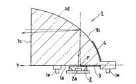
つぎに、本発明を図に示す実施形態に基づいて詳細に説明する。図1、図2に符号1で示すものは、本発明に係る車両用灯具10に係る、例えばアクリル樹脂またはガラス製ののライトガイドブロックであり、このライトガイドブロック1の任意数を備えることで、本発明の車両用灯具10は構成されるものであり、図示は前記ライトガイドブロック1が、光軸Yに対して放物線の上半部を採用したときの例で示してある。
Below, this invention is demonstrated in detail based on embodiment shown in a figure. 1 and FIG. 2 is a light guide block made of acrylic resin or glass, for example, according to the
ここで、本発明においては、前記ライトガイドブロック1は、透明な板状の樹脂など形成され、図1に示すように、光軸Yと下面である入射面1aとは一致、あるいはほぼ一致させられ、前記光軸Yを基準として放物線である反射面1bが現れるものとされている。尚、この実施形態では光を放射するための光放出面1cは入射面1aに対して鉛直あるいはほぼ鉛直な平面として形成されている例で示してあるが、例えば、表面にレンズカットを行うなどの変形は自在である。
Here, in the present invention, the light guide block 1 is formed of a transparent plate-like resin or the like, and as shown in FIG. 1, the optical axis Y and the
前記ライトガイドブロック1が、上記の説明のように形成されたことで、このライトガイドブロック1の焦点Fは、前記入射面1a、即ち、光軸Yと一致、あるいはほぼ一致する面上に存在するものとなり、本発明では、前記光放出面1c方向から見て、焦点Fが存在する位置の近傍から後方(光放出面1cとは反対側)に塗装、蒸着などにより遮光膜3を形成するなどの遮光処理を行う。
Since the light guide block 1 is formed as described above, the focal point F of the light guide block 1 exists on the
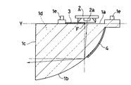
また、本発明では、前記入射面1aの焦点Fの近傍には、例えば出射部が平面状のチップタイプのLEDランプなど光源2が配置されるものとされるが、図2に底面図で示すように、前記光源2の発光素子2aは、前記遮光膜3の前方寄り、即ち、光放出面1c寄りに取付けられている。従って、放物線により形成されている前記反射面1bに対して発光素子2aは焦点Fよりも前方に存在するものとなり、前記反射面1bに反射した後には、水平から下向きとして光放出面1cから外部に放射されるものとなる。
Further, in the present invention, a
ここで図1中に符号4で示すものは、光源2(発光素子2a)からの光が反射面1bに達したときに、内面で全反射が行われない部分に設けられる反射膜であり、この反射膜4は、典型的にはアルミニウムの真空蒸着、塗装、別部材による取付けなどこの種の車両用灯具1の生産に常套的に採用されている手段で形成されている。
Here, what is indicated by reference numeral 4 in FIG. 1 is a reflection film provided on a portion where total reflection is not performed on the inner surface when light from the light source 2 (
尚、上記した反射膜4は適宜な膜厚とすれば光を透過しないものとすることができるので、蒸着時間を適宜に調整するなどの手段で、上記に説明した遮光膜3と同一の工程で形成することが可能となり、生産効率の向上が図れるものとなる。
In addition, since the above-described reflective film 4 can be made to transmit no light if it has an appropriate film thickness, it is the same process as the light-
また、図中に符号1eで示されるものは、例えば、光源2が給電可能に取付けられた回路基板(図示は省略する)上に前記ライトガイドブロック1を固定するための取付ピンであり、この取付ピン1eにより前記光源2と前記ライトガイドブロック1とが前記した回路基板上の相互の位置が、所定の位置として取付けられるものとなる。
Also, what is indicated by
以上説明のように、前記ライトガイドブロック1を形成したことで、光軸Yが水平となるように車両などにライトガイドブロック1を取付けた状態では、遮光膜3と反射面1bとの作用により、上向き光を生じることのない照射光が得られるものとなり、且つ、遮光膜3の作用により発光素子2aから斜め方向後方に放射される光を遮蔽する効果が得られるものとなるので、図3にも示すように明確な明暗境界線を有する配光特性Dが得られるものとなる。
As described above, since the light guide block 1 is formed, when the light guide block 1 is mounted on a vehicle or the like so that the optical axis Y is horizontal, the
尚、このときに、発光素子2aの一部と遮光膜3の一部が重なり合うようにしておくと、遮光膜3は発光素子2aの一部を覆うものとなり、即ち、光輝している発光素子2aの発光面積の一部が遮光膜3により覆われるので、これにより得られる明暗境界線は一層にコントラストが強くなり、より明確な明暗境界線が得られるものとなる。このとき発光面積にに係る遮光の割合は、発光面積の直径が3mm、反射面の焦点距離が10mmのとき直径の1/4程度、(面積的には15%)が望ましい。
At this time, if a part of the
ここで、本発明のライトガイドブロック1の水平方向左右に対する配光に対して考察すれば、発光素子2aからの光は側面(図2参照)により同じ角度の反射を繰り返し、光放出面1cから外部に放射されるものであるので、前記発光素子2aからの放射角と変わることはなく前方に放射される。
Here, considering the light distribution in the horizontal direction of the light guide block 1 of the present invention, the light from the
図5はデザイン上の要求などにより、上記入射面1aと反射面1bとを上下反転させるときの実施形態を示すものであり、このときには、前記遮光膜3を焦点Fの前方、即ち、前記ライトガイドブロック1の光放出面1c側に設けると共に、光源2を焦点Fの後方側に移動させれば良いものとなる。
FIG. 5 shows an embodiment in which the
このようにすることで、ライトガイドブロック1の上下を逆転した場合にも同様な下向き光の配光特性が得られるものとなり、例えば、車両のデザインに応じて両者を使い分けるなどすれば、デザイン面では一層に効果的となる。また、本発明は、上記に述べたように側面1dが平行である必要はなく、図6に断面図で示すように光放出面1cに向かい開く形状としても良く、或いは、閉じる形状としても良いものである。
In this way, the same light distribution characteristic of downward light can be obtained even when the light guide block 1 is turned upside down. For example, if both are used properly according to the design of the vehicle, the design side Then it becomes more effective. In the present invention, the
このときには、側面1dに対して、図6に示すように、開く形状としたときには、光放出面1cから放射される光は発散角度が狭くなり、また、逆に側面1dに対して、閉じる形状としたときには、光放出面1cから放射される光は発散角度が拡がる傾向があるので、例えば、車両用灯具10の中心部と周縁部とで使い分けて、所望の配光特性を得るなども、配光特性の形成上で有効な手段となる。
At this time, when the
1…ライトガイドブロック
1a…入射面
1b…反射面
1c…光放出面
1d…側面
1e…取付ピン
2…光源
2a…発光素子
3…遮光膜
4…反射膜
Y…光軸
DESCRIPTION OF SYMBOLS 1 ...
Claims (4)
この発光素子からの光を車両前方に反射させるための反射面を有するライトガイドブロックとを有し、
このライトガイドブロックが、前記反射面の光軸に沿う鉛直方向への断面形状は、前記光軸上に焦点を有する略放物線形状に設定されており、前記発光素子からの光を前記ライトガイドブロック内部に入射させる入射面は前記光軸を通る水平面で且つ前記焦点と略一致する位置として設定され、
前記入射面には、前記焦点から後方には遮光処理が施され、
前記反射面の一部または全部には、この反射面に達した光を反射させるための反射処理が施されていることを特徴とする車両用灯具。 A light emitting element disposed toward the top of the vehicle;
A light guide block having a reflecting surface for reflecting the light from the light emitting element forward of the vehicle,
In this light guide block, the cross-sectional shape in the vertical direction along the optical axis of the reflecting surface is set to a substantially parabolic shape having a focal point on the optical axis, and light from the light emitting element is transmitted to the light guide block. The incident surface that is incident on the inside is set as a position that is a horizontal plane that passes through the optical axis and substantially coincides with the focal point.
The incident surface is subjected to a light shielding process behind the focal point,
A vehicular lamp, wherein a part or all of the reflection surface is subjected to a reflection process for reflecting light reaching the reflection surface.
このライトガイドブロックが、前記反射面の光軸に沿う鉛直方向への断面形状は、前記光軸上に焦点を有する略放物線形状に設定されており、前記発光素子からの光を前記ライトガイドブロック内部に入射させる入射面は前記光軸を通る水平面で且つ前記焦点と略一致する位置として設定され、前記入射面には、前記焦点から前方には遮光処理が施され、前記反射面の一部または全部には、この反射面に達した光を反射させるための反射処理が施されていることを特徴とする車両用灯具。In this light guide block, the cross-sectional shape in the vertical direction along the optical axis of the reflecting surface is set to a substantially parabolic shape having a focal point on the optical axis, and light from the light emitting element is transmitted to the light guide block. An incident surface incident on the inside is set as a position that is a horizontal plane that passes through the optical axis and substantially coincides with the focal point. The incident surface is subjected to a light shielding process in front of the focal point, and is a part of the reflecting surface. Alternatively, the vehicular lamp is characterized in that a reflection process for reflecting the light reaching the reflecting surface is applied to all.
Priority Applications (1)
| Application Number | Priority Date | Filing Date | Title |
|---|---|---|---|
| JP2006259099A JP4798784B2 (en) | 2006-09-25 | 2006-09-25 | Vehicle lighting |
Applications Claiming Priority (1)
| Application Number | Priority Date | Filing Date | Title |
|---|---|---|---|
| JP2006259099A JP4798784B2 (en) | 2006-09-25 | 2006-09-25 | Vehicle lighting |
Publications (3)
| Publication Number | Publication Date |
|---|---|
| JP2008078086A JP2008078086A (en) | 2008-04-03 |
| JP2008078086A5 JP2008078086A5 (en) | 2009-10-01 |
| JP4798784B2 true JP4798784B2 (en) | 2011-10-19 |
Family
ID=39349923
Family Applications (1)
| Application Number | Title | Priority Date | Filing Date |
|---|---|---|---|
| JP2006259099A Expired - Fee Related JP4798784B2 (en) | 2006-09-25 | 2006-09-25 | Vehicle lighting |
Country Status (1)
| Country | Link |
|---|---|
| JP (1) | JP4798784B2 (en) |
Families Citing this family (19)
| Publication number | Priority date | Publication date | Assignee | Title |
|---|---|---|---|---|
| TWI338637B (en) * | 2008-12-29 | 2011-03-11 | Univ Nat Central | Automobile lamp |
| JP5381351B2 (en) | 2009-06-03 | 2014-01-08 | スタンレー電気株式会社 | Vehicle lighting |
| DE102009037559A1 (en) * | 2009-08-13 | 2011-02-17 | Automotive Lighting Reutlingen Gmbh | Headlamp with a LED-Teilfernlichtmodul |
| JP5445923B2 (en) | 2009-09-04 | 2014-03-19 | スタンレー電気株式会社 | Vehicle lighting |
| JP5516854B2 (en) | 2009-10-08 | 2014-06-11 | スタンレー電気株式会社 | Vehicle lighting |
| JP5481764B2 (en) | 2009-10-08 | 2014-04-23 | スタンレー電気株式会社 | Vehicle lighting |
| JP5486894B2 (en) * | 2009-10-19 | 2014-05-07 | スタンレー電気株式会社 | Vehicle headlamp |
| JP5397186B2 (en) * | 2009-11-24 | 2014-01-22 | スタンレー電気株式会社 | Vehicle lighting |
| US8388200B2 (en) | 2010-02-04 | 2013-03-05 | Stanley Electric Co., Ltd. | Vehicle light with values corresponding to the CIE color space |
| JP5518607B2 (en) * | 2010-07-08 | 2014-06-11 | 株式会社小糸製作所 | Lighting fixtures for vehicles |
| JP5686240B2 (en) * | 2010-10-08 | 2015-03-18 | スタンレー電気株式会社 | Vehicle lighting |
| JP5589930B2 (en) * | 2011-03-30 | 2014-09-17 | 豊田合成株式会社 | Lighting device |
| JP6116823B2 (en) * | 2012-06-29 | 2017-04-19 | 株式会社小糸製作所 | Vehicle lamp and window unit |
| FR3012203B1 (en) * | 2013-10-23 | 2015-10-30 | Valeo Vision | LIGHTING DEVICE COMPRISING A GUIDE OF LUMINOUS RAYS |
| JP6201708B2 (en) * | 2013-12-11 | 2017-09-27 | スタンレー電気株式会社 | Vehicle lamp and lens body |
| JP6265753B2 (en) * | 2014-01-24 | 2018-01-24 | スタンレー電気株式会社 | Vehicle headlamp |
| KR102289727B1 (en) * | 2015-05-22 | 2021-08-13 | 에스엘 주식회사 | Head lamp for vehicle |
| KR102588792B1 (en) * | 2016-02-15 | 2023-10-18 | 엘지이노텍 주식회사 | Lamp and Vehicle having the same |
| JP6793405B2 (en) | 2018-10-31 | 2020-12-02 | 株式会社キャットアイ | Light vehicle lights |
Family Cites Families (10)
| Publication number | Priority date | Publication date | Assignee | Title |
|---|---|---|---|---|
| FR2657680B1 (en) * | 1990-01-26 | 1993-02-05 | Valeo Vision | MOTOR VEHICLE HEADLIGHT COMPRISING AN IMPROVED LIGHT SOURCE. |
| JPH08111103A (en) * | 1994-10-12 | 1996-04-30 | Yazaki Corp | Display device |
| JPH08195103A (en) * | 1994-11-15 | 1996-07-30 | Nippondenso Co Ltd | Lamp tool device for vehicle |
| JP2000348508A (en) * | 1999-06-04 | 2000-12-15 | Stanley Electric Co Ltd | Lighting fixture for vehicle |
| JP2004014895A (en) * | 2002-06-10 | 2004-01-15 | Yoshio Takada | Light emitting body 2 |
| JP2004071409A (en) * | 2002-08-07 | 2004-03-04 | Denso Corp | Vehicular lighting fixture and light distribution control method for same |
| JP4024628B2 (en) * | 2002-09-03 | 2007-12-19 | 株式会社小糸製作所 | Vehicle headlamp |
| JP4047186B2 (en) * | 2003-02-10 | 2008-02-13 | 株式会社小糸製作所 | Vehicle headlamp and optical unit |
| JP4339143B2 (en) * | 2004-02-10 | 2009-10-07 | 株式会社小糸製作所 | Vehicle lamp unit |
| JP2006127856A (en) * | 2004-10-27 | 2006-05-18 | Koito Mfg Co Ltd | Vehicular lighting lamp |
-
2006
- 2006-09-25 JP JP2006259099A patent/JP4798784B2/en not_active Expired - Fee Related
Also Published As
| Publication number | Publication date |
|---|---|
| JP2008078086A (en) | 2008-04-03 |
Similar Documents
| Publication | Publication Date | Title |
|---|---|---|
| JP4798784B2 (en) | Vehicle lighting | |
| US11085603B2 (en) | Motor vehicle headlight module for emitting a light beam | |
| JP7022068B2 (en) | Vehicle lighting | |
| CN108474532B (en) | Vehicle lamp and substrate | |
| JP5945857B2 (en) | Vehicle headlamp and light guide lens | |
| JP4930787B2 (en) | VEHICLE LIGHT AND LIGHT GUIDE LENS USED FOR VEHICLE LIGHT | |
| JP6516495B2 (en) | Vehicle lamp | |
| US20130235605A1 (en) | LED Light Module | |
| JP6609135B2 (en) | Rear combination lamp for vehicles | |
| JP2009064729A (en) | Lighting fixture unit for vehicle | |
| JP2013016327A (en) | Vehicular lamp unit | |
| JP5397186B2 (en) | Vehicle lighting | |
| JP2008078086A5 (en) | ||
| US10612743B2 (en) | Vehicle lamp | |
| CN109027943A (en) | Headlight for automobile and the vehicle for utilizing it | |
| CN113167452A (en) | Light guide for vehicle and vehicle lamp | |
| JP5445049B2 (en) | Vehicle lighting | |
| CN101149141A (en) | Projection-type vehicle headlamp | |
| EP2570715A2 (en) | Vehicle headlamp | |
| JP2011181277A (en) | Headlight for vehicle | |
| JP5446757B2 (en) | Vehicle lighting | |
| JP6221438B2 (en) | Vehicle lighting | |
| JP2008147003A (en) | Lamp unit of vehicular headlamp | |
| JP2020155352A (en) | Vehicular lighting fixture | |
| JP6518459B2 (en) | Vehicle lamp |
Legal Events
| Date | Code | Title | Description |
|---|---|---|---|
| A521 | Request for written amendment filed |
Free format text: JAPANESE INTERMEDIATE CODE: A523 Effective date: 20090819 |
|
| A621 | Written request for application examination |
Free format text: JAPANESE INTERMEDIATE CODE: A621 Effective date: 20090819 |
|
| A977 | Report on retrieval |
Free format text: JAPANESE INTERMEDIATE CODE: A971007 Effective date: 20110107 |
|
| A131 | Notification of reasons for refusal |
Free format text: JAPANESE INTERMEDIATE CODE: A131 Effective date: 20110201 |
|
| A521 | Request for written amendment filed |
Free format text: JAPANESE INTERMEDIATE CODE: A523 Effective date: 20110330 |
|
| TRDD | Decision of grant or rejection written | ||
| A01 | Written decision to grant a patent or to grant a registration (utility model) |
Free format text: JAPANESE INTERMEDIATE CODE: A01 Effective date: 20110705 |
|
| A01 | Written decision to grant a patent or to grant a registration (utility model) |
Free format text: JAPANESE INTERMEDIATE CODE: A01 |
|
| A61 | First payment of annual fees (during grant procedure) |
Free format text: JAPANESE INTERMEDIATE CODE: A61 Effective date: 20110801 |
|
| FPAY | Renewal fee payment (event date is renewal date of database) |
Free format text: PAYMENT UNTIL: 20140812 Year of fee payment: 3 |
|
| R150 | Certificate of patent or registration of utility model |
Ref document number: 4798784 Country of ref document: JP Free format text: JAPANESE INTERMEDIATE CODE: R150 Free format text: JAPANESE INTERMEDIATE CODE: R150 |
|
| R250 | Receipt of annual fees |
Free format text: JAPANESE INTERMEDIATE CODE: R250 |
|
| R250 | Receipt of annual fees |
Free format text: JAPANESE INTERMEDIATE CODE: R250 |
|
| R250 | Receipt of annual fees |
Free format text: JAPANESE INTERMEDIATE CODE: R250 |
|
| R250 | Receipt of annual fees |
Free format text: JAPANESE INTERMEDIATE CODE: R250 |
|
| R250 | Receipt of annual fees |
Free format text: JAPANESE INTERMEDIATE CODE: R250 |
|
| R250 | Receipt of annual fees |
Free format text: JAPANESE INTERMEDIATE CODE: R250 |
|
| R250 | Receipt of annual fees |
Free format text: JAPANESE INTERMEDIATE CODE: R250 |
|
| R250 | Receipt of annual fees |
Free format text: JAPANESE INTERMEDIATE CODE: R250 |
|
| LAPS | Cancellation because of no payment of annual fees |